CyberTAN Technology ISB7105 Internet Protocal Set Top Box Basic SD/HD with WiFi User Manual
CyberTAN Technology Inc. Internet Protocal Set Top Box Basic SD/HD with WiFi
UserManual.wiki
>
CyberTAN Technology
>
ISB7105 User Manual
User manual
Navigation menu
Upload a User Manual
Namespaces
Wiki Guide
HTML
PDF
Info
Views
User Manual
Discussion / Help
Navigation
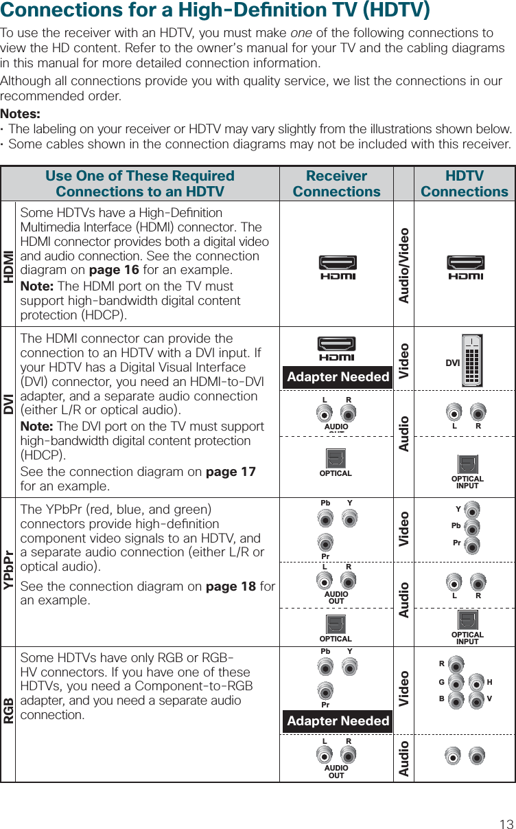
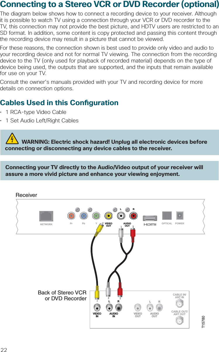
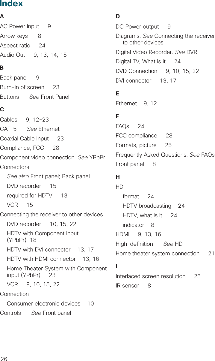
![17Connecting to an HDTV with a DVI ConnectorCables Used in this Con guration• 1 HDMI-to-DVI Cable or 1 HDMI Cable and 1 HDMI-to-DVI Adapter• 1 Audio Left/Right Cable (You can also use an optical cable [indicated by the dotted line] instead of the Audio Left/Right Cable as shown in the diagram, dependent upon your TV’s capabilities.)Notes:• The DVI port on the TV must support high-bandwidth digital content protection (HDCP).• When you connect the HDMI connector to the DVI connector on your HDTV, you need an HDMI-to-DVI adapter and a separate audio connection. WARNING: Electric shock hazard! Unplug all electronic devices before connecting or disconnecting any device cables to the receiver.ReceiverNETWORKLRPr Pb Y VIDEOOUT AUDIOOUT OPTICAL POWERBack of HDTVAUDIOCENTERCHANNEL INANT (75 )INOUTANT-1HD 2YOUTANT-2PBPRLRVIDEOL/MONORL/MONORAUDIOINON OFFINHD 1S-VIDEOVIDEO YPBPRLRAUDIOAUDIODVI/HDCPINAUDIO INDVI/HDCPLROPTICALINPUTORT15775](https://usermanual.wiki/CyberTAN-Technology/ISB7105/User-Guide-1856355-Page-15.png)
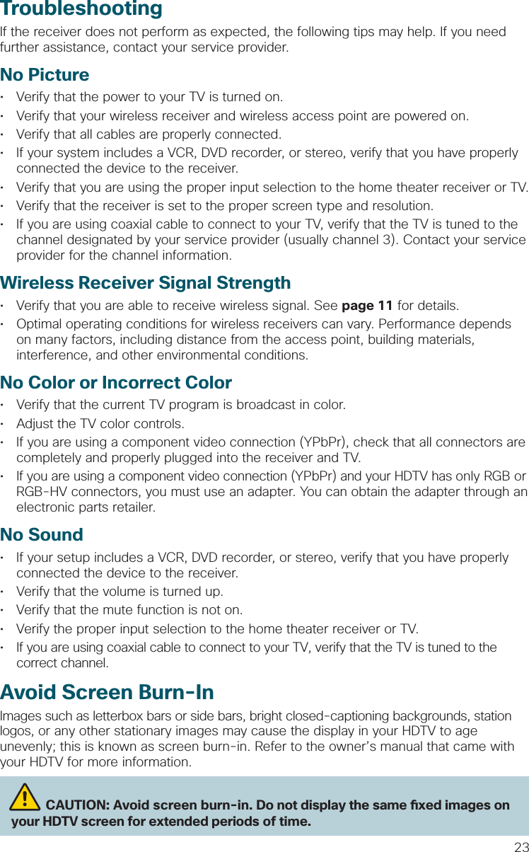
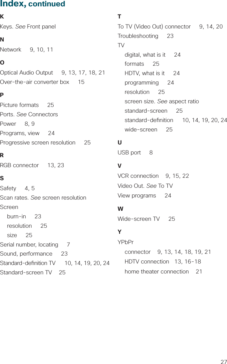
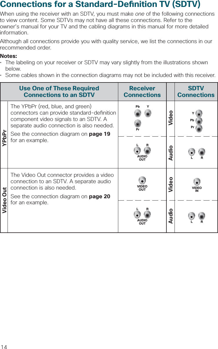
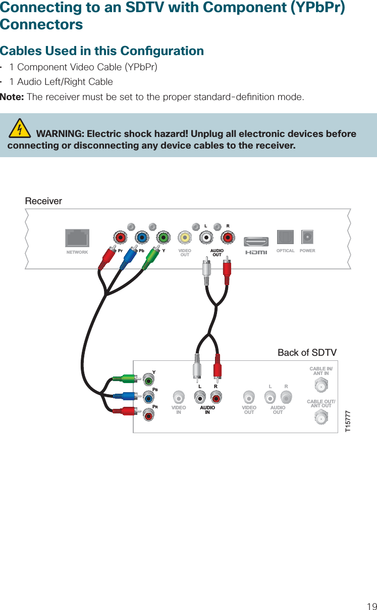
![18Connecting to an HDTV with Component (YPbPr) ConnectorsCables Used in this Con guration• 1 Component Video Cable (YPbPr)• 1 Audio Left/Right Cable (You can also use an optical cable [indicated by the dotted line] instead of the Audio Left/Right Cable as shown in the diagram, dependent upon your TV’s capabilities.) WARNING: Electric shock hazard! Unplug all electronic devices before connecting or disconnecting any device cables to the receiver.ReceiverT15776NETWORKLRPr Pb Y VIDEOOUT AUDIOOUT OPTICAL POWERBack ofHDTVHDMIAUDIOCENTERCHANNEL INAUDIO INDVI/HDCPANT (75 )INOUTLRANT-1HD 2YOUTANT-2PBPRLRVIDEOL/MONORL/MONORAUDIOINON OFFS-VIDEOVIDEOAUDIOINHD 1YPBPRLRAUDIOOPTICALINPUTOR](https://usermanual.wiki/CyberTAN-Technology/ISB7105/User-Guide-1856355-Page-16.png)
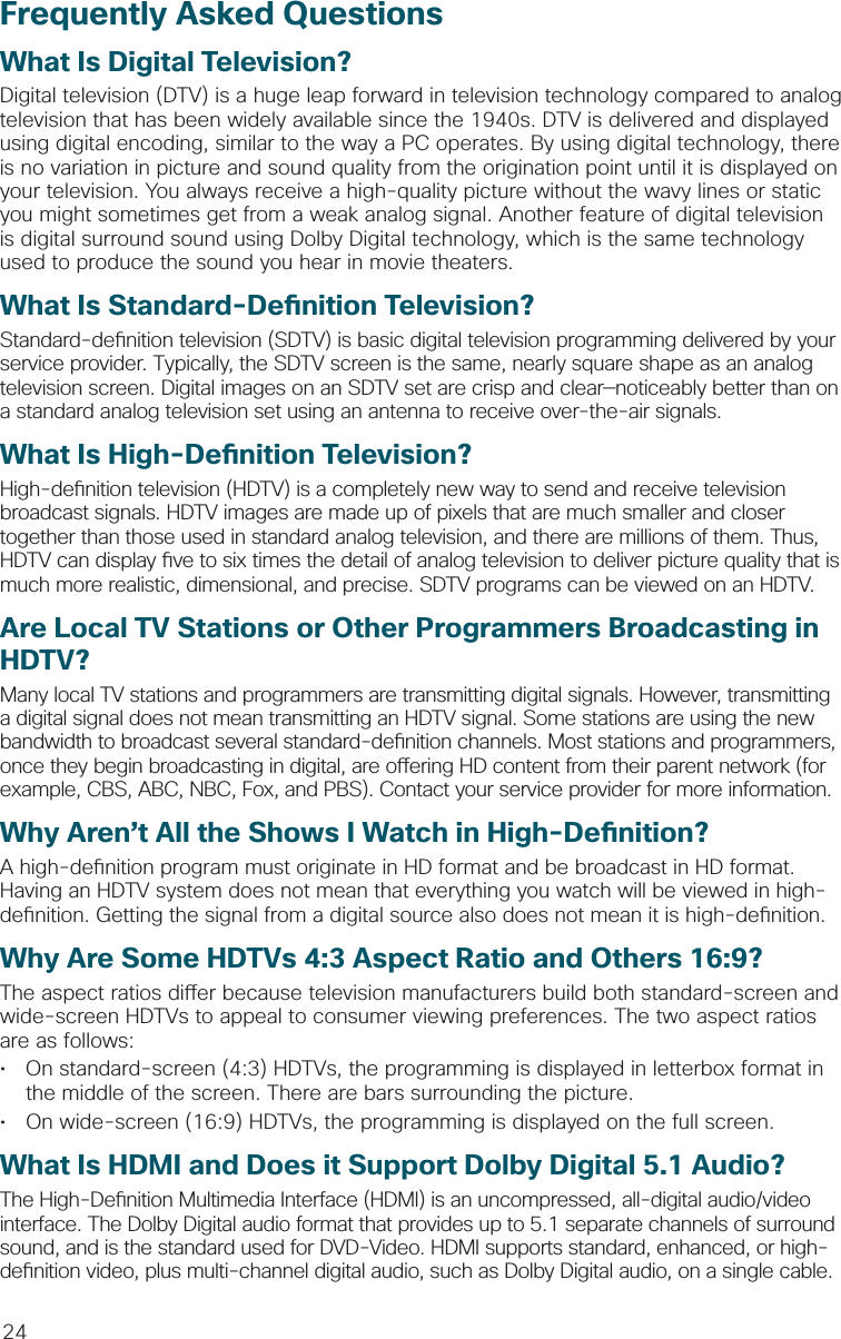
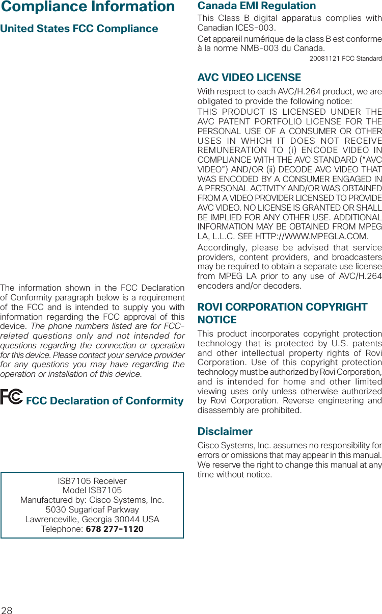
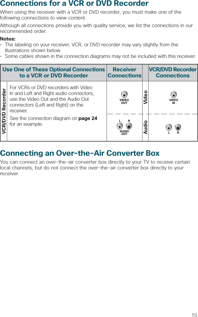
![21Connecting to a Home Theater System with Component (YPbPr) ConnectorsCables Used in this Con guration• 1 Component Video Cable (YPbPr)• 1 Audio Left/Right Cable (You can also use an optical cable [indicated by the dotted line] instead of the Audio Left/Right Cable as shown in the diagram.)Notes:• This connection requires that audio is provided by the home theater system.• Consult the user guide that came with your home theater system for information on connecting your other video and audio devices. WARNING: Electric shock hazard! Unplug all electronic devices before connecting or disconnecting any device cables to the receiver.T15779ReceiverNETWORKLRPr Pb Y VIDEOOUT AUDIOOUT OPTICAL POWERBack of HomeTheater ReceiverCOMPONENT VIDEO1YPBPR2YPBPRYPBPRS-VIDEODIGITALAUDIO TV/CABLE1234VIDEOLRAUDIOS-VIDEODVDVIDEOLRAUDIOVIDEOLRAUDIOS-VIDEOVIDEO 1S-VIDEOOUTVIDEO OUTMONITORVIDEOLRAUDIOS-VIDEOOUTINOUTINOR](https://usermanual.wiki/CyberTAN-Technology/ISB7105/User-Guide-1856355-Page-19.png)