CyberTAN Technology MM230M IEEE 802.11b/g Bluetooth 2.0+ EDR and GPS MiniCard User Manual
CyberTAN Technology Inc. IEEE 802.11b/g Bluetooth 2.0+ EDR and GPS MiniCard Users Manual
UserManual.wiki
>
CyberTAN Technology
>
MM230M User Manual
>
Users Manual
Contents
1.
Users Manual
2.
manual
3.
User manual host specification
4.
Host user manual 1 of 2
5.
Host user manual 2 of 2
6.
User manual 1 of 2
7.
User manual 2 of 2
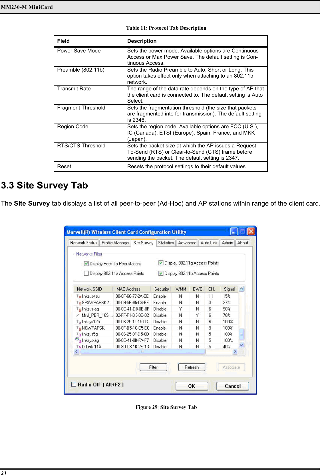
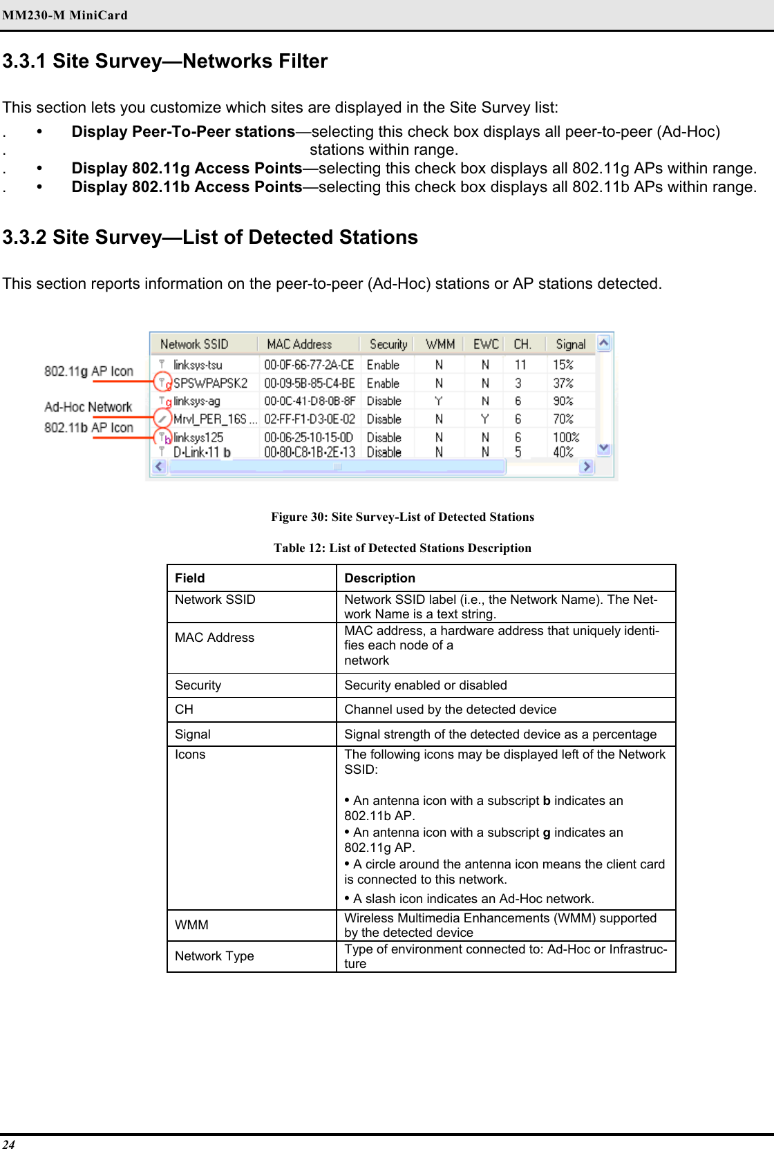
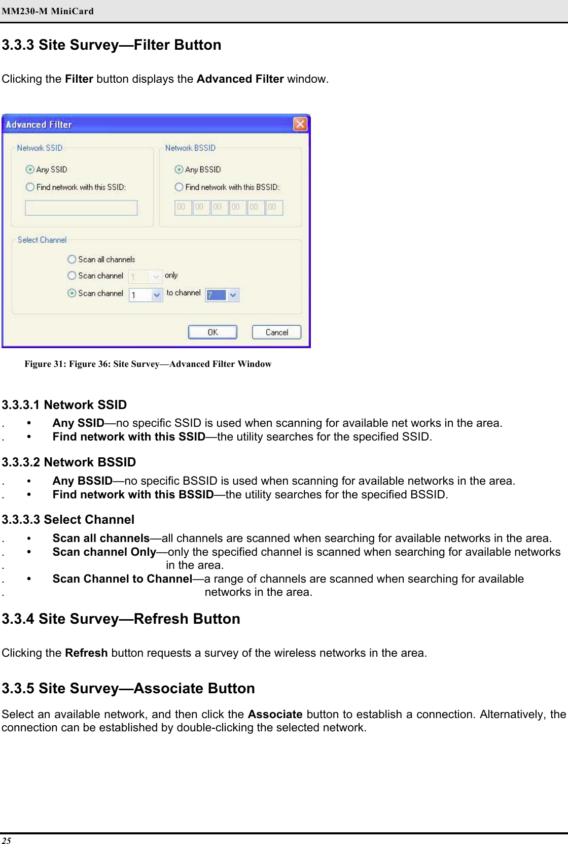
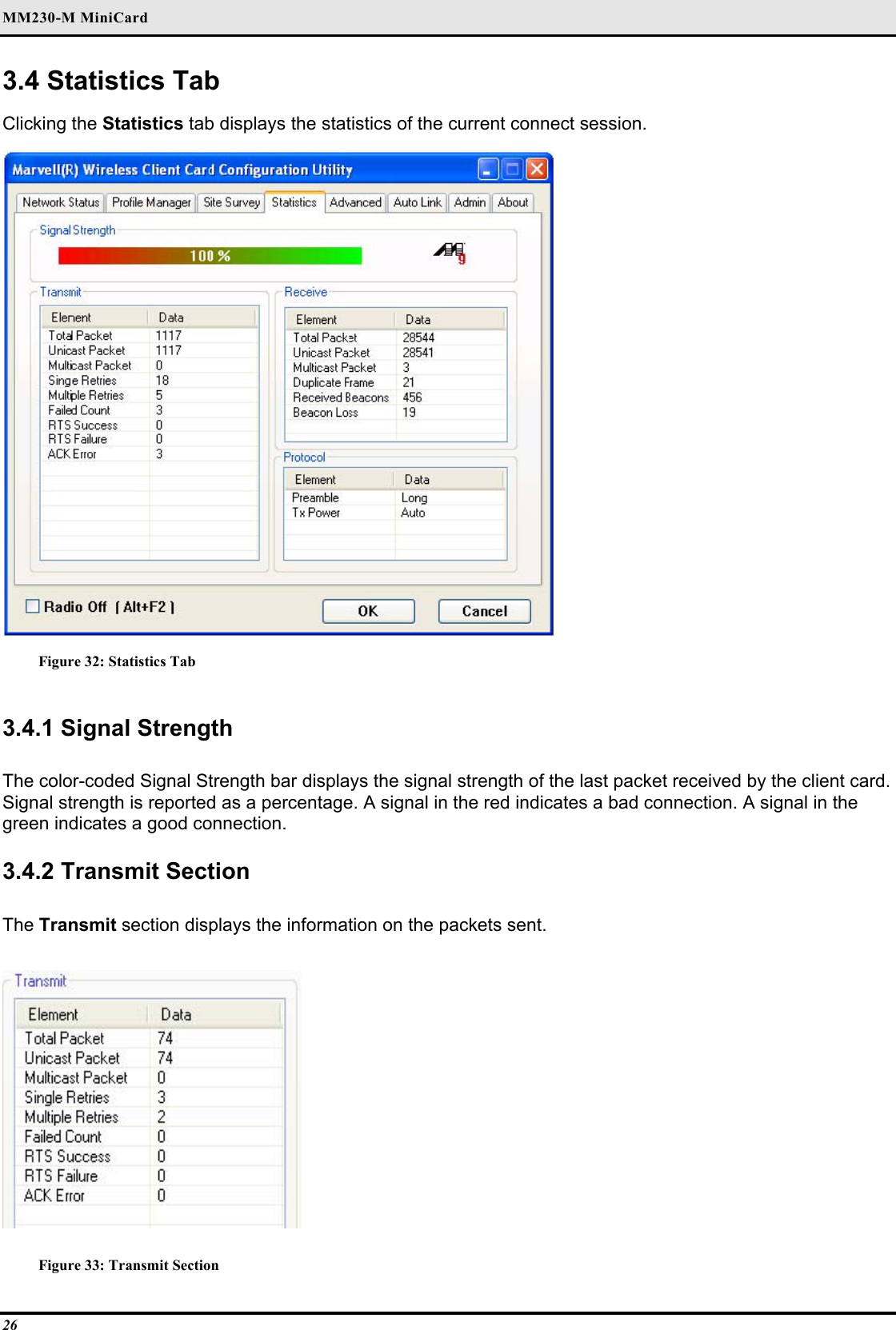
Users Manual
Navigation menu
Upload a User Manual
Namespaces
Wiki Guide
HTML
PDF
Info
Views
User Manual
Discussion / Help
Navigation