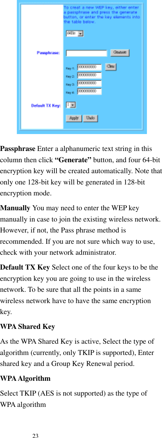
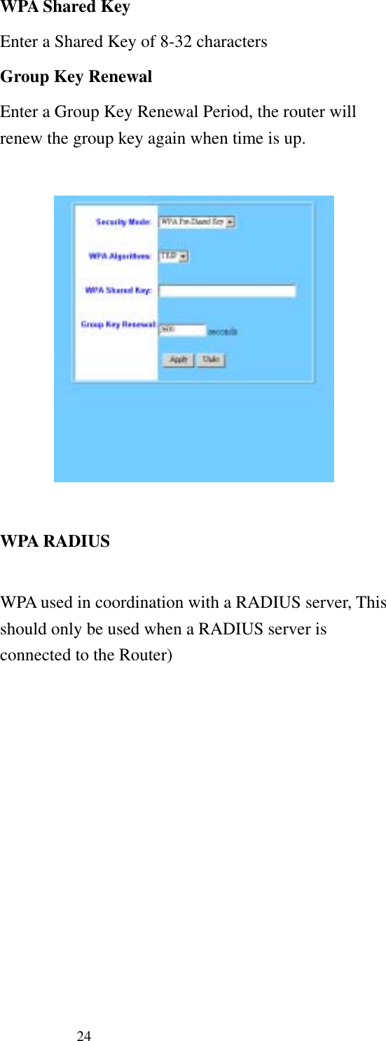
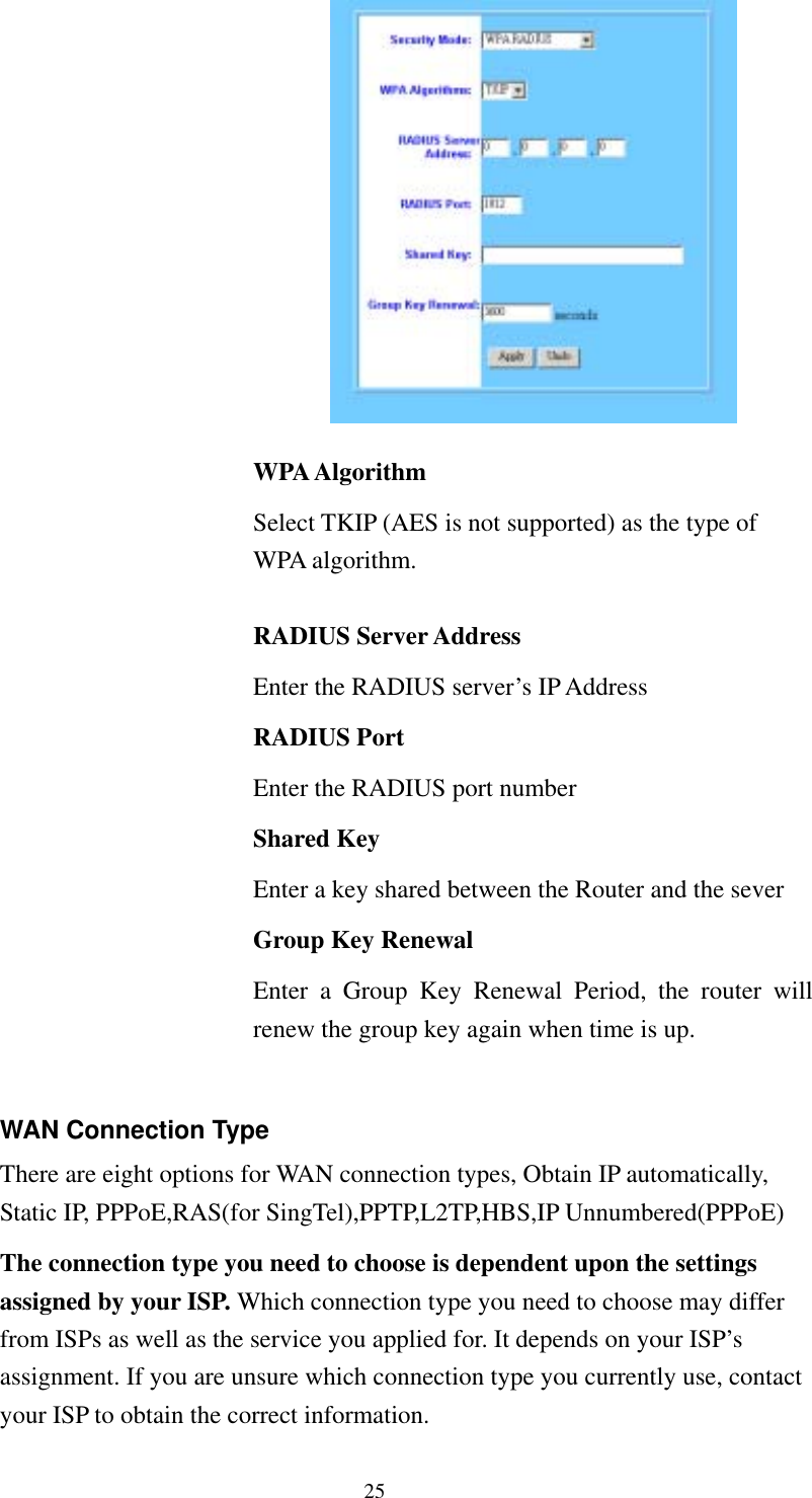
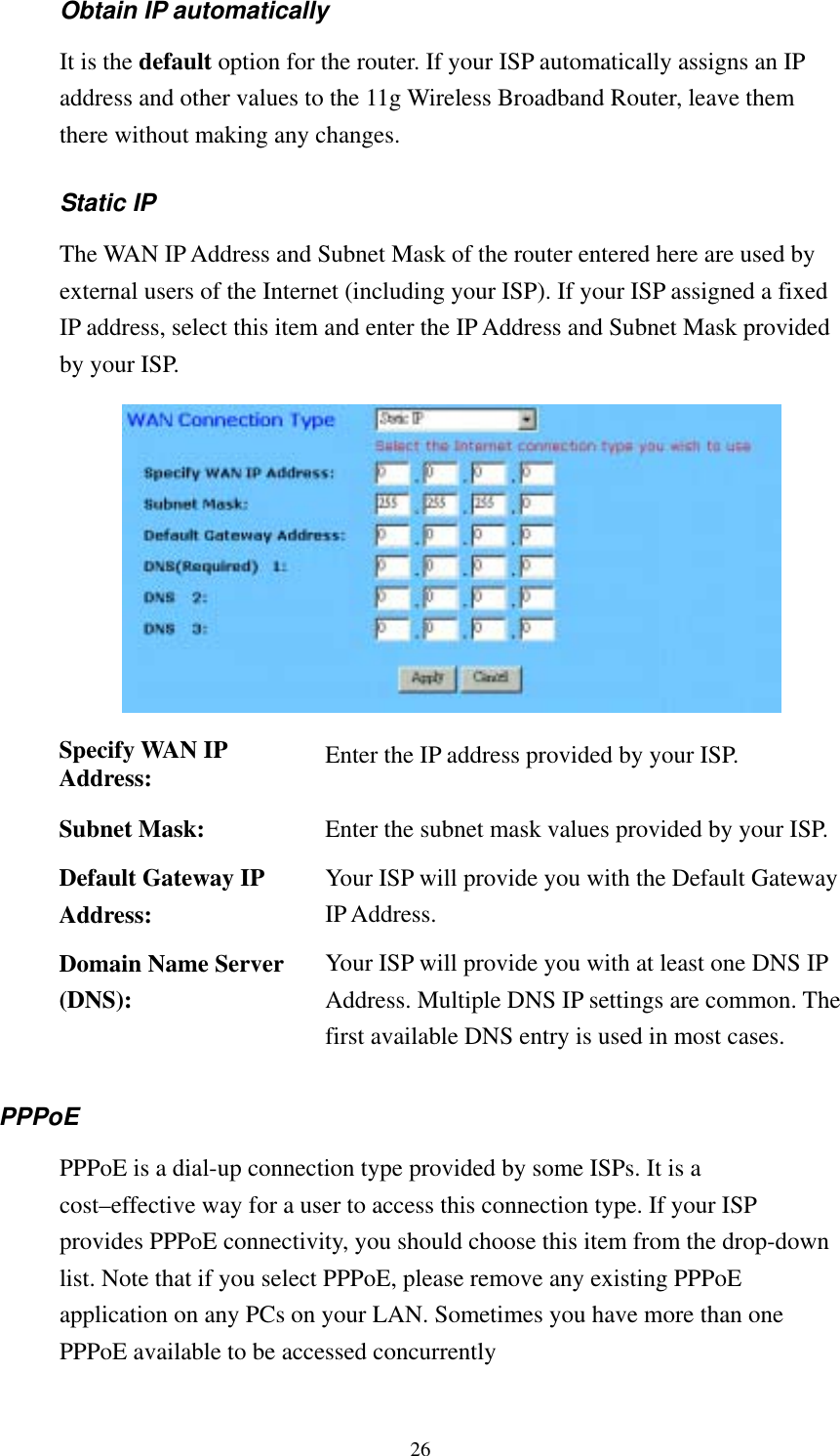
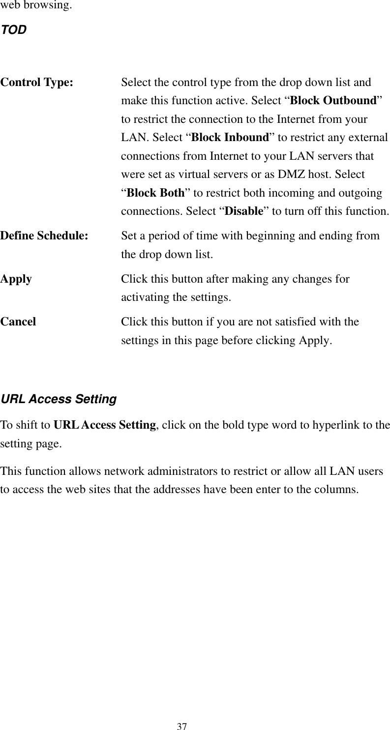
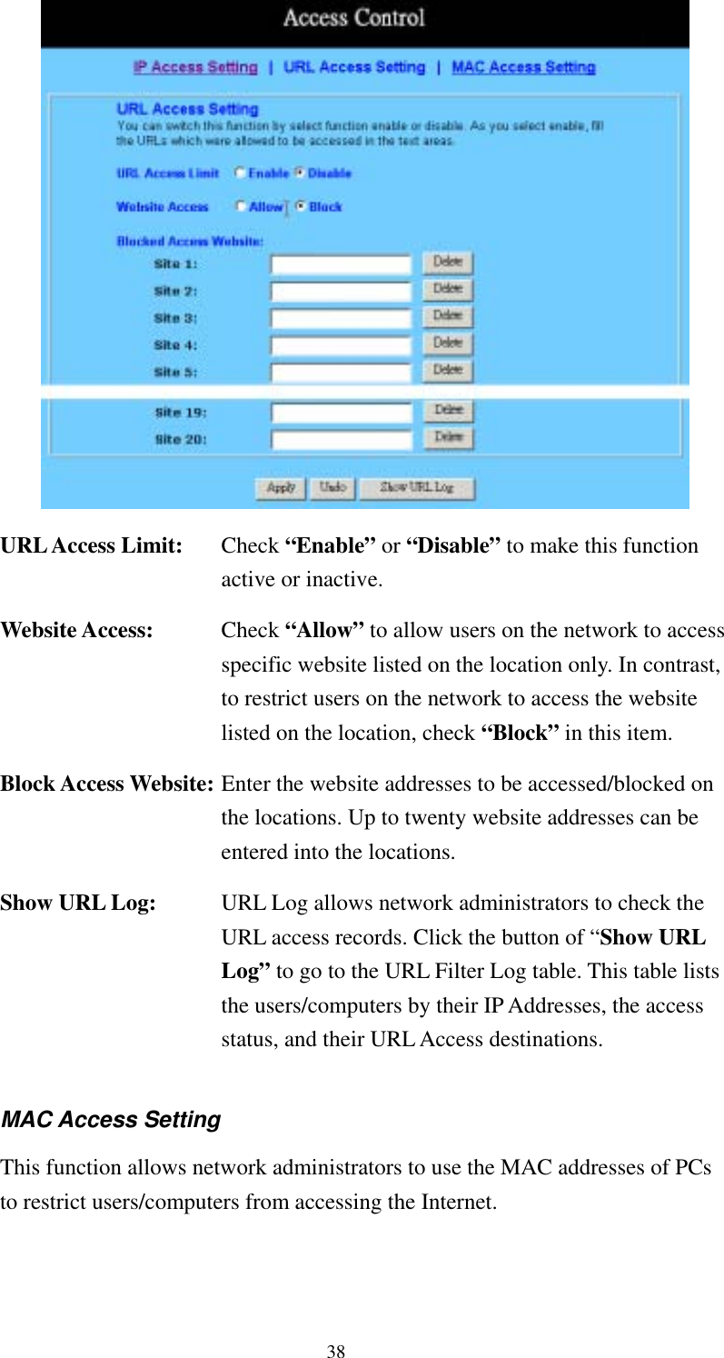
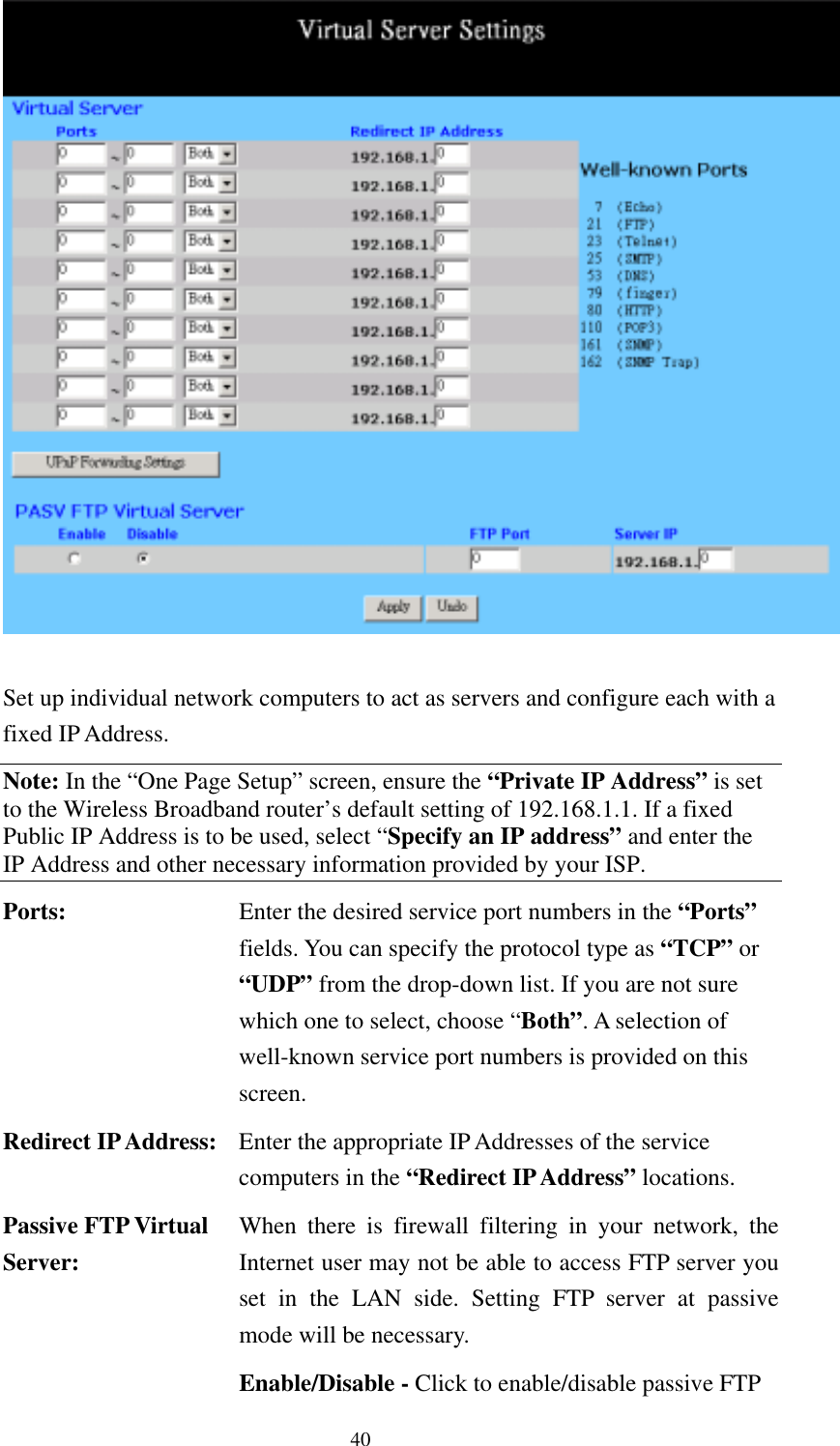
CyberTAN Technology WG214A 11G broadband wireless router User Manual
CyberTAN Technology Inc. 11G broadband wireless router
UserManual.wiki
>
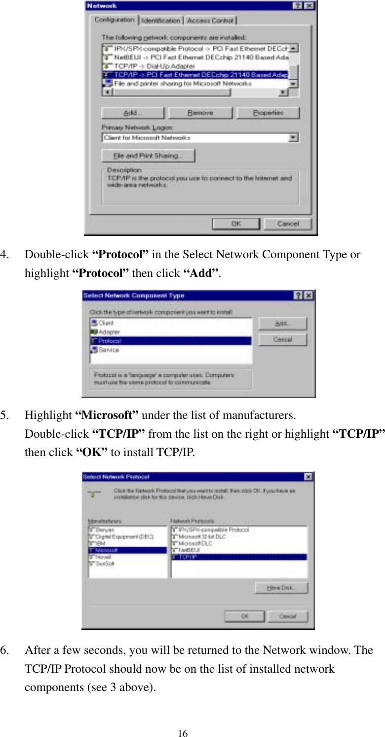
CyberTAN Technology
>
WG214A User Manual
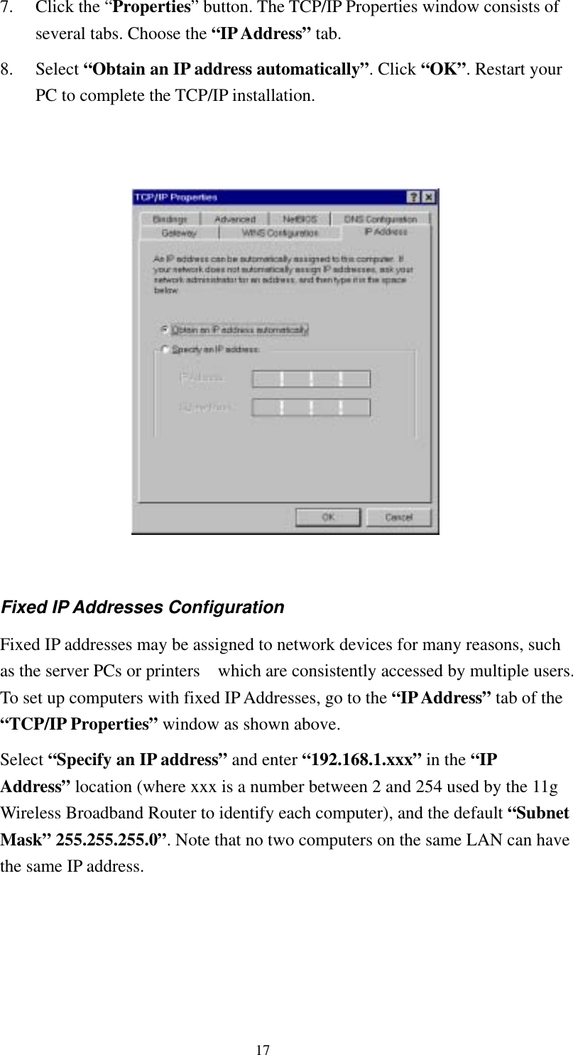
User Manual
Navigation menu
Upload a User Manual
Namespaces
Wiki Guide
HTML
PDF
Info
Views
User Manual
Discussion / Help
Navigation