CyberTAN Technology WG414B1 11g Wireless Security Router User Manual
CyberTAN Technology Inc. 11g Wireless Security Router
UserManual.wiki
>
CyberTAN Technology
>
WG414B1 User Manual
User Manual
Navigation menu
Upload a User Manual
Namespaces
Wiki Guide
HTML
PDF
Info
Views
User Manual
Discussion / Help
Navigation
![11g Wireless Security Router User Guide - 68 - 4. Deselect the Activate the default response rule check box, and then click Next button. 5. Click the Finish button, making sure the Edit check box is checked. C-2.2 Build 2 Filter Lists: “WinXPÆBroadband VPN Router” and “Broadband VPN RouterÆWinXP”. [Filter List 1] WinXPÆ Broadband VPN Router 1. In the to_VPNRouter Properties, deselect the Use Add Wizard check box, and then click Add button to create a new rule.](https://usermanual.wiki/CyberTAN-Technology/WG414B1/User-Guide-365575-Page-74.png)
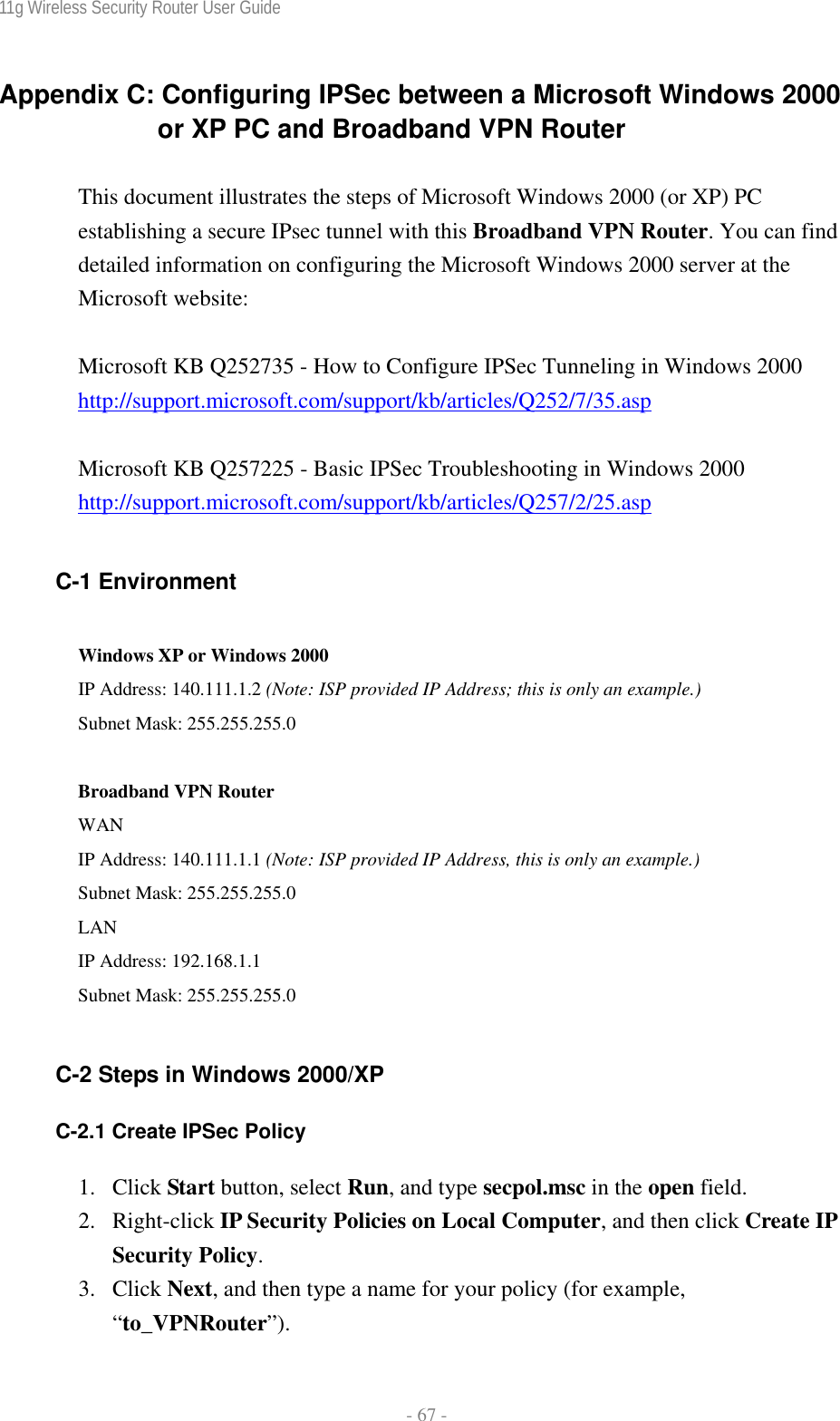
![11g Wireless Security Router User Guide - 70 - 6. If you want to type a description for your filter, click the Description tab. 7. Click OK button. Then click OK(for WinXP) or Close (for Win2000) button on the IP Filter List Window. [Filter List 2] Broadband VPN RouterÆWinXP 1. On the IP Filter List tab, click the Add button. 2. Type an appropriate name “Broadband VPN RouterÆXP” for the filter list, click to clear the Use Add Wizard check box, and then click Add. 3. In the Source address area, click A specific IP Subnet, and fill in the IP](https://usermanual.wiki/CyberTAN-Technology/WG414B1/User-Guide-365575-Page-76.png)
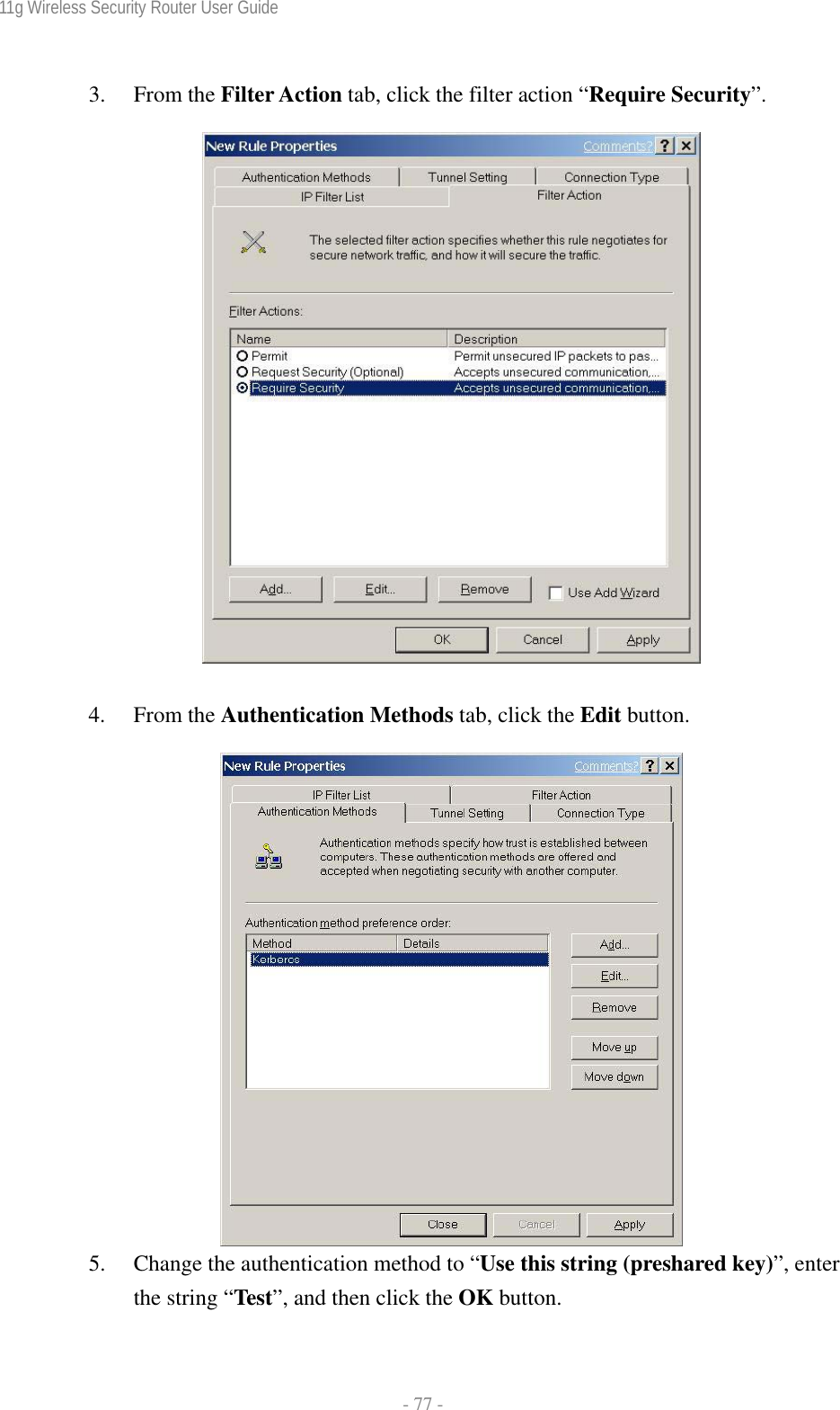
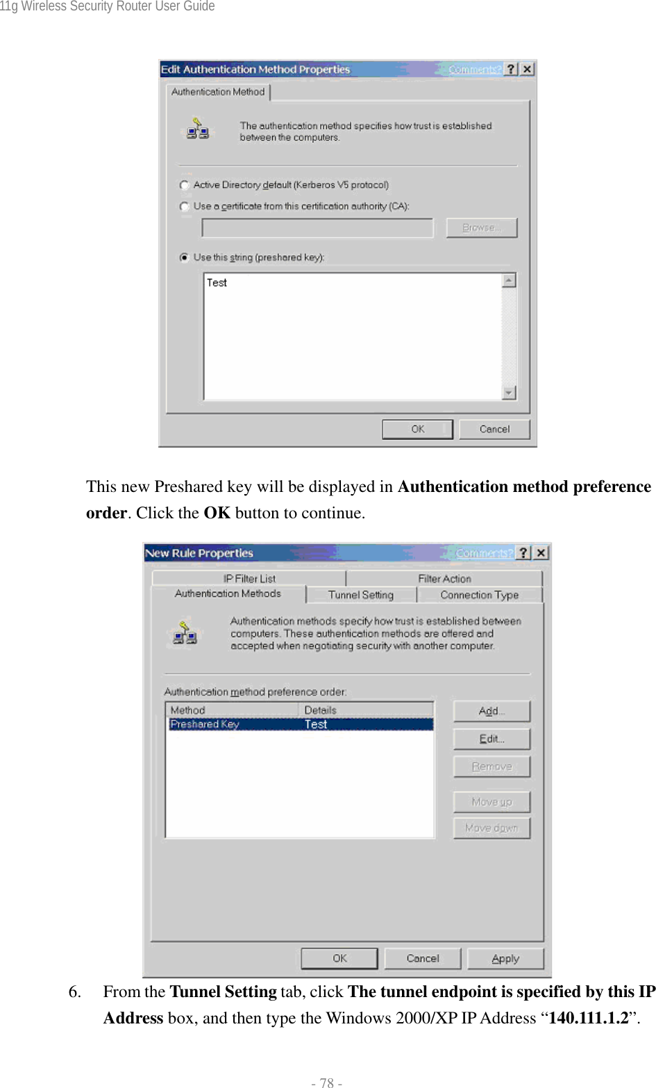
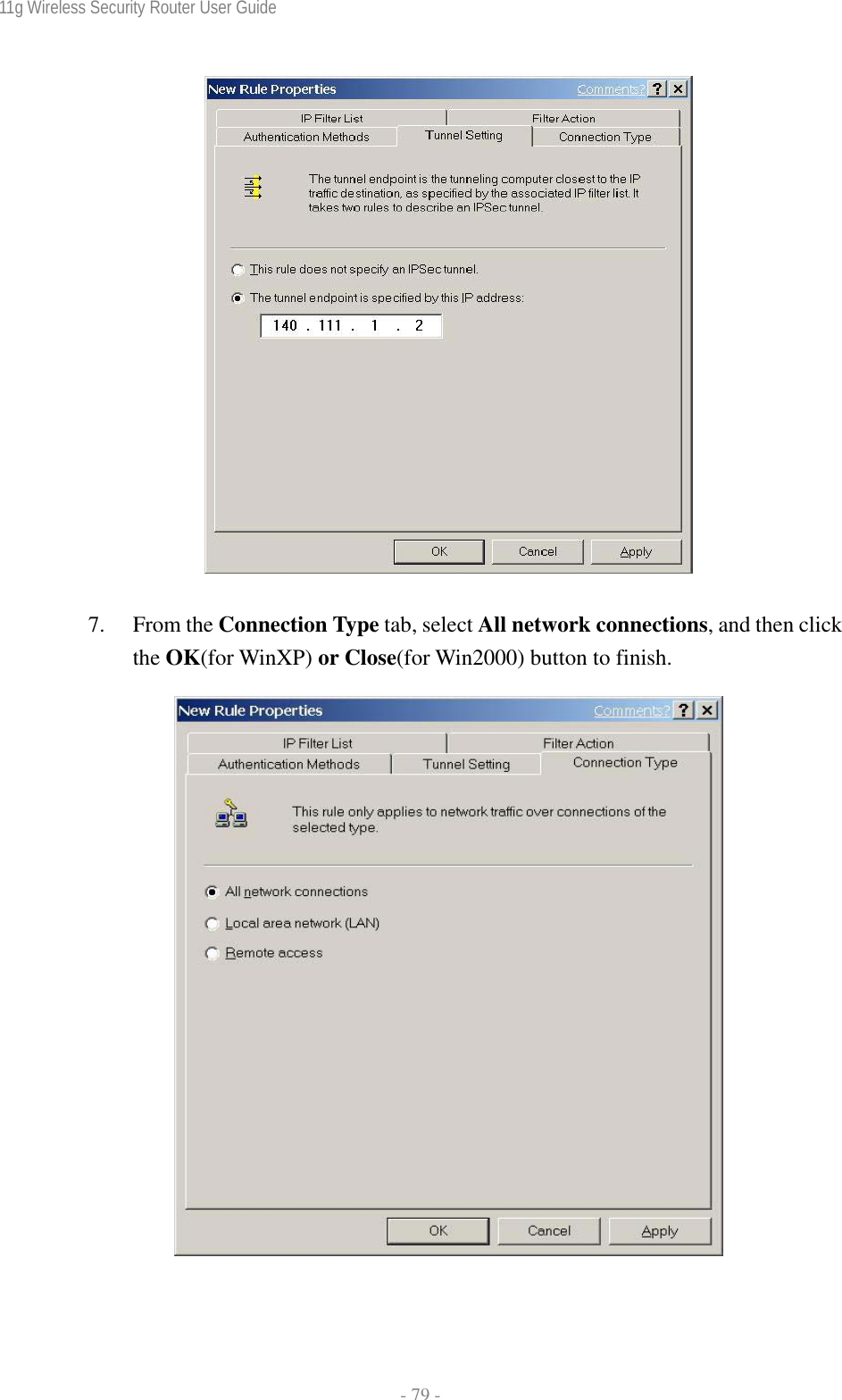
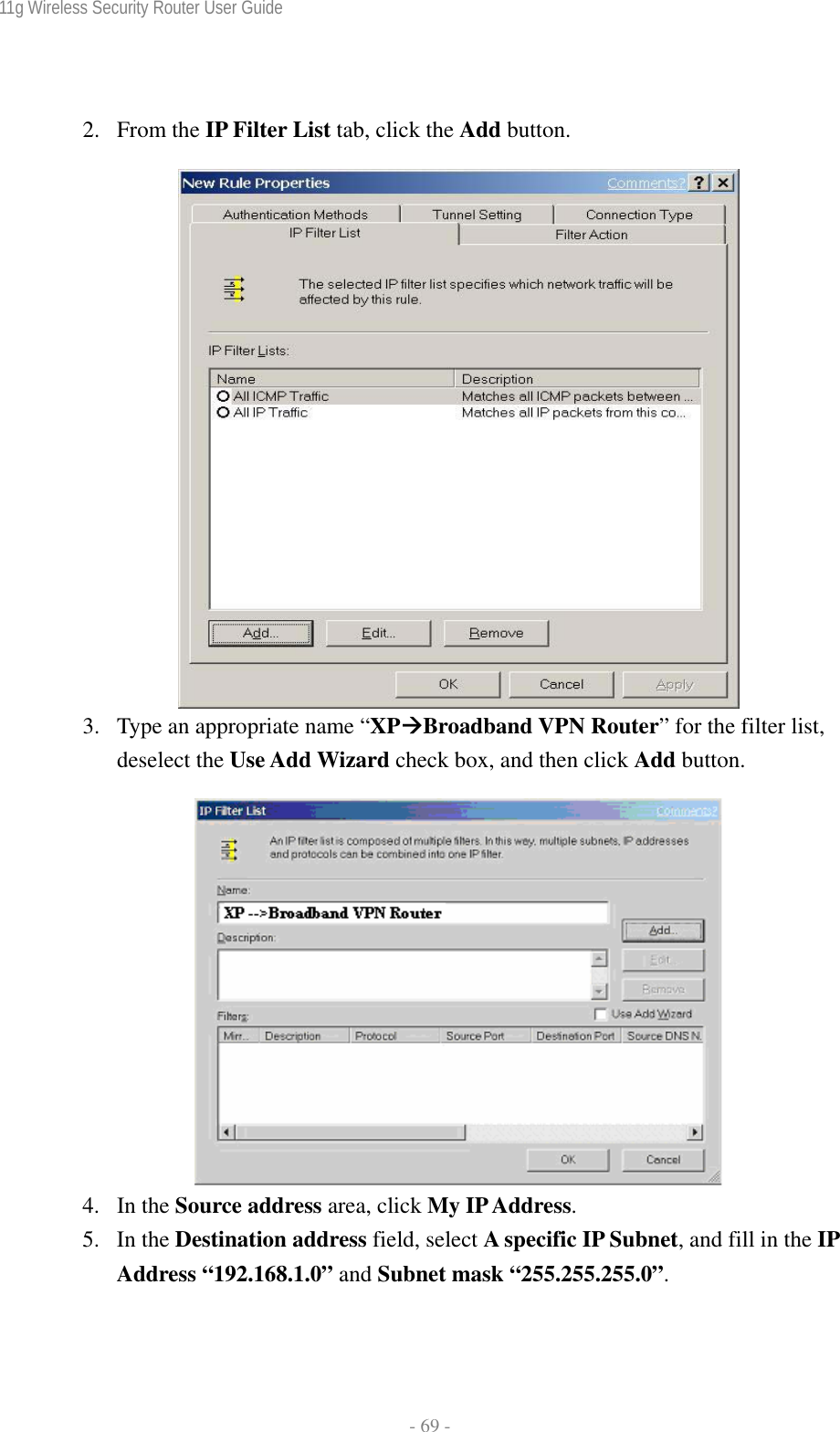
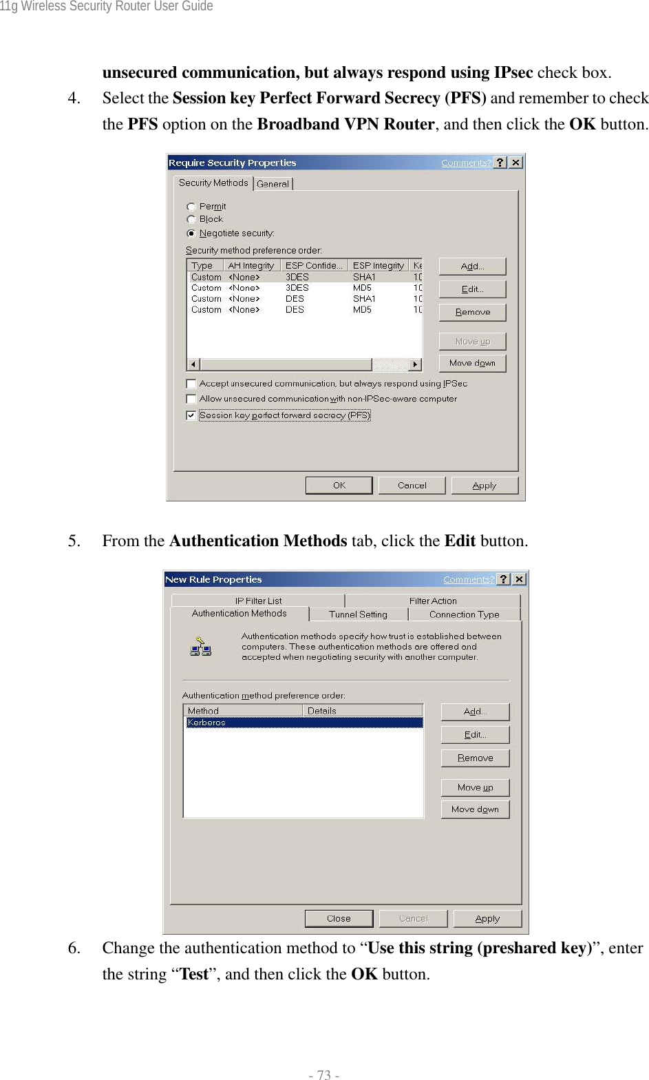
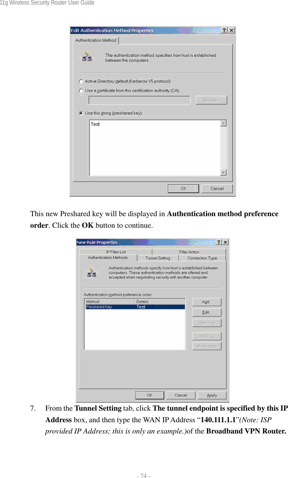
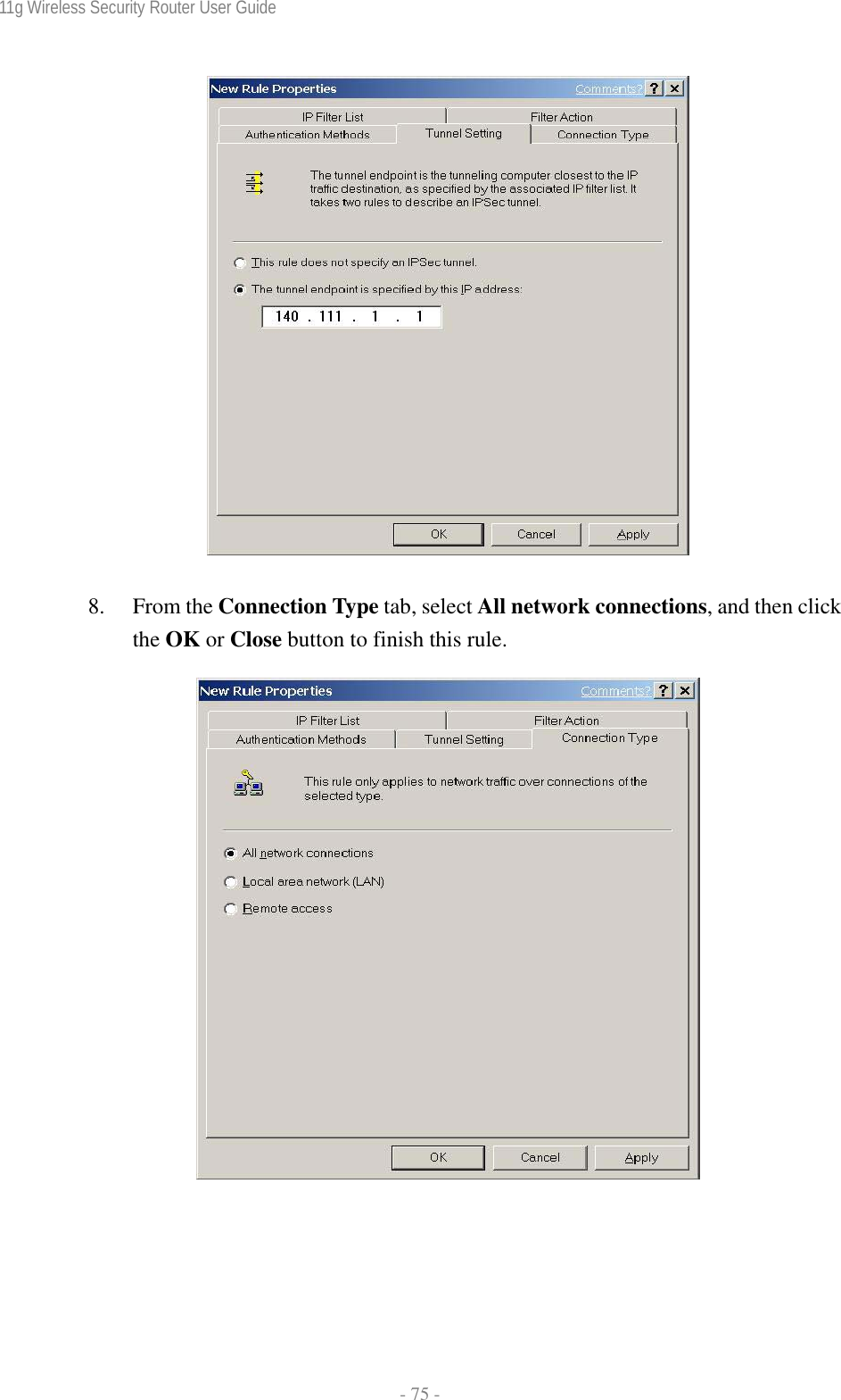
![11g Wireless Security Router User Guide - 71 - Address “192.168.1.0” and Subnet mask “255.255.255.0”. 4. In the Destination address area, click My IP Address. 5. If you want to type a description for your filter, click the Description tab. 6. Click OK, and then click OK. C-2.3 Configure Individual Rule of 2 Tunnels [Tunnel 1] WinXPÆBroadband VPN Router 1. From the IP Filter List tab, click the filter list “XPÆBroadband VPN](https://usermanual.wiki/CyberTAN-Technology/WG414B1/User-Guide-365575-Page-77.png)
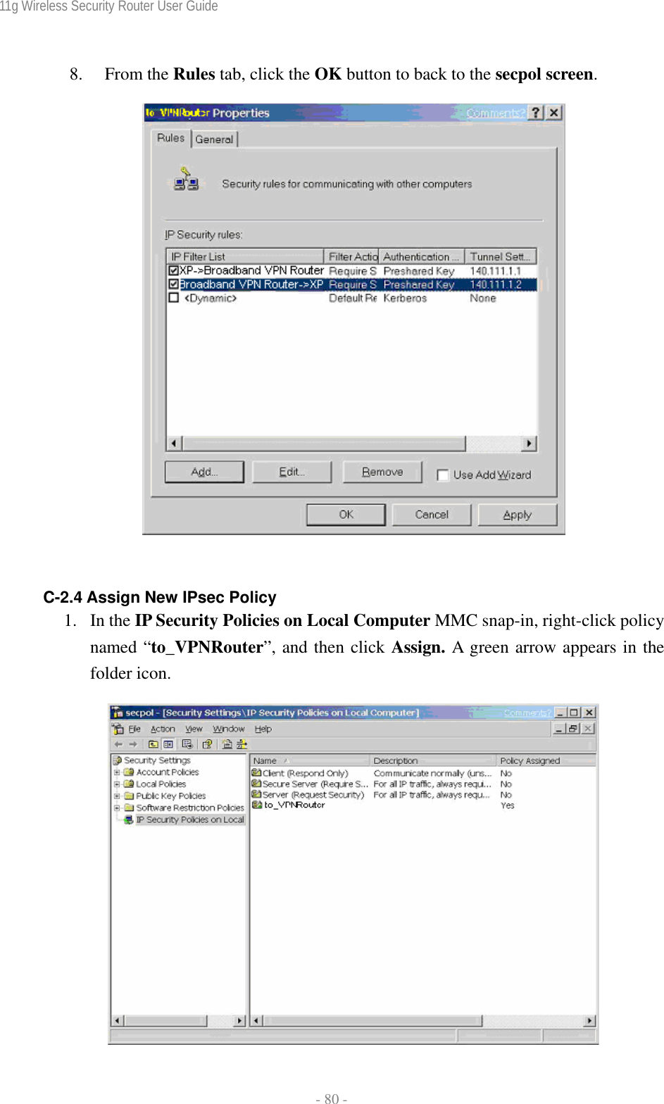
![11g Wireless Security Router User Guide - 76 - [Tunnel 2] Broadband VPN RouterÆ WinXP 1. In the to_VPNRouter Properties, deselect the Use Add Wizard check box, and then click the Add button to create the second IP Filter. 2. On the IP Filter List tab, click the filter list “Broadband VPN RouterÆXP”.](https://usermanual.wiki/CyberTAN-Technology/WG414B1/User-Guide-365575-Page-82.png)