CyberTAN Technology WG414B1 11g Wireless Security Router User Manual
CyberTAN Technology Inc. 11g Wireless Security Router
User Manual
1
11
1g
g
W
Wi
ir
re
el
le
es
ss
s
S
Se
ec
cu
ur
ri
it
ty
y
R
Ro
ou
ut
te
er
r
User Guide
8/05/2003
11g Wireless Security Router User Guide
- ii -
FCC Interference Statement
This device complies with Part 15 of FCC rule. Operation is subject to the following two
conditions:
9 This device may not cause harmful interference.
9 This device must accept any interference received, including interference that
may cause undesired operation.
This 11g Wireless Security Router has been tested and found to comply with the limits
for a Class B digital device, pursuant to Part 15 of the FCC Rules. These limits are
designed to provide reasonable protection against harmful interference in a residential
installation. This equipment generates, uses, and can radiate radio frequency energy and,
if not installed and used according to the instructions, may cause harmful interference to
radio communications. However, there is no guarantee that interference will not occur in
a particular installation.
If this equipment does cause harmful interference to radio or television reception, which
is found by turning the equipment off and on, the user is encouraged to try to correct the
interference by one or more of the following measures:
9 Reorient or relocate the receiving antenna.
9 Increase the separation between the equipment or device.
9 Connect the equipment to an outlet other than the receiver’s.
9 Consult a dealer or an experienced radio/TV technician for assistance.
FCC Radiation Exposure Statement
This equipment complies with FCC radiation exposure limits set forth for an
uncontrolled anvironment. This equipment should be installed and operated with
minimum distance 20cm between the radiator and your body.
CE Declaration of Conformity:
This equipment complies with the specifications relating to electromagnetic
compatibility, EN 55022/A1 Class B, and EN 50082-1. This meets the reasonable
protection requirements set out in the European Council Directive on the approximation
of the laws of the member states relating to Electromagnetic Compatibility Directive
(89/336/EEC).
11g Wireless Security Router User Guide
- iii -
Manufacturer’s Disclaimer State
The information in this document is subject to change without notice and does not
represent a commitment on the part of vendor. No warranty or representation, either
expressed or implied, is made with respect to the quality, accuracy or fitness for any
particular prupose of this document. The manufacturer reserves the right to make change
to the content of this document and/or the products associated with it at any time without
obligation to notify any person or organization. In no event will the manufacturer be
liable for direct, indirect, special, incidental or consequential damages arising out of the
use or inability to use this product or documentation, even if advised of the possibility of
such damages. This document contains materials protected by copyright. All rights are
reserved. No part of this manual may be reproduced or transmitted in any form, by any
means or for any purpose without expressed written consent of its authors. Product
names appearing in this document are mentioned for identification purchases only. All
trademarks, product names or brand names appearing in this document are registered
property of their respective owners.
11g Wireless Security Router User Guide
- iv -
Table of Contents
INTRODUCTION................................................................................................................................................. 1
About this Guide............................................................................................................................................ 1
Chapter 1: Get to know your 11g Wireless Security Router .......................................................................... 1
Chapter 2: Hardware Installation & Setup ................................................................................................... 1
Chapter 3: Internet Access ............................................................................................................................ 2
Chapter 4: Advanced Applications................................................................................................................ 2
Chapter 5: Management................................................................................................................................ 2
Chapter 6: Macintosh Setup.......................................................................................................................... 2
Chapter 7: Trouble Shooting ......................................................................................................................... 2
Conventions................................................................................................................................................... 2
CHAPTER 1: GETTING TO KNOW YOUR 11G WIRELESS SECURITY ROUTER................................ 3
1-1 ABOUT THE 11G WIRELESS SECURITY ROUTER ............................................................................................ 3
Ethernet / Fast Ethernet ................................................................................................................................ 3
Wireless LAN ................................................................................................................................................. 3
1-2 CONTENTS OF THE 11G WIRELESS SECURITY ROUTER PACKAGE .................................................................. 4
1-3 FEATURES OF THE 11G WIRELESS SECURITY ROUTER ................................................................................... 4
CHAPTER 2: HARDWARE INSTALLATION & SETUP ............................................................................... 6
2-1 REAR PANEL & CONNECTIONS...................................................................................................................... 6
2-2 FRONT PANEL LEDS..................................................................................................................................... 6
2-3 SYSTEM REQUIREMENTS AND SETUP ............................................................................................................ 7
CHAPTER 3: INTERNET ACCESS................................................................................................................. 13
3-1 PREPARE YOUR NETWORK INFORMATION .................................................................................................... 13
3-2 WEB-BASED USER INTERFACE .................................................................................................................... 13
3-3 INITIAL CONFIGURATION – SETUP ............................................................................................................... 14
CHAPTER 4: ADVANCED APPLICATIONS ................................................................................................. 21
4-1 FIREWALL ................................................................................................................................................... 21
4-2 VPN SETTINGS ........................................................................................................................................... 22
4-3 DHCP CONFIGURATION .............................................................................................................................. 30
4-4 WEB CONTROL ........................................................................................................................................... 31
4-5 TOD CONTROL............................................................................................................................................ 32
4-6 ACCESS CONTROL....................................................................................................................................... 33
4-7 VIRTUAL SERVER SETTINGS ........................................................................................................................ 35
4-8 SPECIAL APPLICATIONS............................................................................................................................... 39
11g Wireless Security Router User Guide
- v -
4-9 DMZ HOST ................................................................................................................................................. 40
4-10 DYNAMIC ROUTING .................................................................................................................................. 42
4-11 STATIC ROUTING ....................................................................................................................................... 43
4-12 WIRELESS ................................................................................................................................................. 44
4-13 DDNS....................................................................................................................................................... 47
CHAPTER 5: MANAGEMENT........................................................................................................................ 49
5-1 DEVICE ADMINISTRATION SETTINGS........................................................................................................... 49
5-2 STATUS MONITOR ....................................................................................................................................... 52
5-3 LOG............................................................................................................................................................. 53
5-4 BACKUP & RESTORE ................................................................................................................................... 54
5-5 UPGRADE FIRMWARE .................................................................................................................................. 55
5-6 DIAGNOSTIC-PING/TRACERT....................................................................................................................... 56
Ping ............................................................................................................................................................. 56
Tracert ......................................................................................................................................................... 57
CHAPTER 6: MACINTOSH SETUP............................................................................................................... 58
6-1 HARDWARE CONNECTIONS ......................................................................................................................... 58
6-2 COMPUTER NETWORK CONFIGURATION ..................................................................................................... 58
6-2.1 Dynamic IP Addressing using DHCP Server...................................................................................... 58
6-2.2 Manual Configuration of Fixed IP Addresses .................................................................................... 58
6-3 11G WIRELESS SECURITY ROUTER CONFIGURATION................................................................................... 59
6-4 ADDING 11G WIRELESS SECURITY ROUTER TO EXISTING NETWORK .......................................................... 59
CHAPTER 7: TROUBLE SHOOTING............................................................................................................ 61
CHAPTER 7: TROUBLE SHOOTING............................................................................................................ 61
HARDWARE....................................................................................................................................................... 61
CLIENT SIDE (COMPUTERS)...............................................................................................................................62
APPENDIX A: FREQUENTLY ASKED QUESTIONS .................................................................................. 64
APPENDIX B: TECHNICAL SPECIFICATIONS.......................................................................................... 66
APPENDIX C: CONFIGURING IPSEC BETWEEN A MICROSOFT WINDOWS 2000 OR XP PC AND
BROADBAND VPN ROUTER.......................................................................................................................... 67
C-1 ENVIRONMENT ........................................................................................................................................... 67
C-2 STEPS IN WINDOWS 2000/XP..................................................................................................................... 67
C-2.1 Create IPSec Policy........................................................................................................................... 67
11g Wireless Security Router User Guide
- vi -
C-2.2 Build 2 Filter Lists: “WinXP
Æ
Broadband VPN Router” and “Broadband VPN Router
Æ
WinXP”. 68
C-2.3 Configure Individual Rule of 2 Tunnels ............................................................................................. 71
C-2.4 Assign New IPsec Policy ................................................................................................................... 80
APPENDIX D: GLOSSARY.............................................................................................................................. 81
11g Wireless Security Router User Guide
- 1 -
Introduction
Congratulations on your purchase of this 11g Wireless Security Router . This router is the
perfect design product combining wireless and Ethernet network technology together.
Fully compatible with IEEE 802.11g wireless standard, this device not only allows you to
take advantage of mobility, but also to have fast Ethernet connection with built-in four
10/100 auto-sensing switch Ethernet ports. Users on wireless LAN and Ethernet LAN
can share files, printers, and other networking resource each other at a blazing speed.
Best of all, with NAT technology, all users can share single account of Internet access by
having this device connect to a DSL/Cable modem.
Integrated 802.11g wireless AP and 4-port 10/100 Mbps switch, it is quick and easy to
deploy wireless and wire LAN without spending extra cost of a wireless access point, hub
or switch. All LAN users are able to share internal network data, like files, printers, and
other networking resources in a blazing speed. The wireless Router’s efficient antenna
offers a covered range up to 30 meters indoor (150 meters outdoor) and seamless roaming
throughout wireless LAN infrastructure. More over, the wireless operation provides 64
bit key and 128 bit WEP data encryption for high-level security.
With built-in NAT, this device not only provides natural firewall, protecting your network
from access by outside users but also extends your LAN connection. Users on the LAN
can share a single account of Internet access by having this device connect to a
DSL/Cable modem. This Firewall Router allows up to 253 users on the Ethernet LAN
simultaneously but makes IP configuration simple and easy. Configured as a DHCP
server, the 11g Wireless Security Router assigns an IP Address to every connected PC on
Ethernet LAN automatically. Also, DHCP client helps WAN port obtain IP address
dynamically assigned by ISP.
With a web-based UI (User Interface), this 11g Wireless Security Router is easy to setup
and maintain. With this exclusive user friendly interface, all functions can be configured
easily via a web browser such as Netscape Communicator and Internet Explorer.
About this Guide
This guide contains information about installing and configuring your 11g Wireless
Security Router . It is designed to guide users through the correct setup procedures for
appropriate hardware installation and basic configuration. Later, it shows how to
complete advanced configurations to get the best operating performance from this 11g
Wireless Security Router .
Chapter 1: Get to know your 11g Wireless Security Router
This chapter describes the package contents and provides a list of features and
applications illustrations of the 11g Wireless Security Router .
Chapter 2: Hardware Installation & Setup
This chapter describes the steps for the hardware installation of the 11g Wireless Security
Router .
11g Wireless Security Router User Guide
- 2 -
Chapter 3: Internet Access
This chapter describes the steps for the basic configuration and start up of the 11g
Wireless Security Router .
Chapter 4: Advanced Applications
This chapter describes how to configure advanced functions in order to get the most from
your 11g Wireless Security Router .
Chapter 5: Management
This Chapter describes how to configure management functions in order to manage and
get the setting information of your 11g Wireless Security Router .
Chapter 6: Macintosh Setup
This Chapter provides instructions on how to set up your Macintosh computers in your
network.
Chapter 7: Trouble Shooting
This chapter describes any potential problems you may encounter and the suggested
remedies.
Conventions
The following explains the conventions used throughout this document.
Italics New words, terms, or special emphasis. E.g. Getting to know your
11g Wireless Security Router .
“Boldface” Buttons, checkboxes, or items that you can select from screens,
menus, or dialog boxes. E.g. Click “OK” to restart
Boldface Italics Items in Bold Italics are samples only and you should enter other
names, numbers, or words to substitute.

11g Wireless Security Router User Guide
- 3 -
Chapter 1: Getting to know your 11g Wireless Security Router
This chapter describes the package contents and provides a list of features and
application illustrations of the 11g Wireless Security Router.
1-1 About The 11g Wireless Security Router
The 11g Wireless Security Router is a hybrid design product which combines Ethernet
technology and wireless access into a single stand-alone unit. The device allows you take
advantages of both mobility and fast connection. All PCs whenever on wireless LAN or
Ethernet LAN can share files, printers and other network resource. Moreover, all users
can share single account of Internet access by having this device connect to a DSL/Cable
modem.
Ethernet / Fast Ethernet
Ethernet is the most widely-used network access method, especially in a Local Area
Nnetwork (LAN) and is defined by the IEEE as the 802.3 standard. Normally, Ethernet is
a shared media LAN. All stations on the segment share the total bandwidth, which could
be 10Mbps (Ethernet), 100Mbps (Fast Ethernet), or 1000Mbps (Gigabit Ethernet). With
a switched Ethernet, each sender and receiver has the full bandwidth.
Fast Ethernet is defined as IEEE 802.3u standard, a high-speed version of Ethernet with
100Mbps transmission rate.
Wireless LAN
Wireless Local Area Network systems (WLANs) transmit and receive data through the
air by using radio frequency (RF). This offers some advantages like mobility, ease of
installation, and scalability over traditional wired systems.
Mobility: WLANs combine data connectivity with user mobility. This provides users
with access to network anywhere in their organization. For example, users can roam from
a conference room to their office without being disconnected from the LAN. This is
impossible with wired networks.
Ease of Installation: Eliminating the need to deploy network cable in walls and ceilings,
Installing WLANs is easy for novice and expert users alike.
Scalability: WLAN topologies are easy to change in various ways from peer-to-peer
networks for a small group of users to full infrastructure networks for hundreds of users
roaming over a broad area.
Wireless LAN is suitable for difficult-to-wire and frequently changing environments. It’s
also an ideal solution for mobile workers to access network resource and for setting a
temporary LAN when necessary
Wireless LANs can be set as “Aad-hoc” network and “Infrastructure” network. Unlike
the “Aad-hoc network”, where users on the LAN send data directly to each other, the
“Infrastructure” network includes an access point and users on the “Infrastructure”
11g Wireless Security Router User Guide
- 4 -
network send data to that dedicated access point. 11g Wireless Security Router uses
“Infrastructure” network as Wireless LANs. Each wireless LAN PC within the range of
the access point can communicate with other wireless LAN PCs within the range.
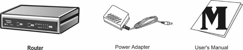
1-2 Contents of the 11g Wireless Security Router Package
After carefully unpacking the shipping carton, check the contents listed below.
1. 11g Wireless Security Router.
2. Power Adapter.
3. User’s Manual
4. UTP Cable (not showing)
1-3 Features of the 11g Wireless Security Router
Your 11g Wireless Security Router contains the following features that make it excellent
for network connections.
9 Allows multiple users to access the Internet at the same time by providing
maximum Internet utilization to multiple users sharing a single public IP Address.
9 Allows users on Ethernet LAN and Wireless LAN to transfer data to each other
through wireless-to-wire bridge.
9 Provides wireless access roaming, best access point selection, loading balance,
network traffic filtering included in wireless roaming function.
9 Provides 64bits/128bits key WEP (Wired Equivalent Privacy) wireless data
encryption to secure wireless communication.
9 Fully supports 802.11 open and shared key authentications.
9 Integrates four 10/100BASE-T/TX auto-sensing switch ports.
9 Uses NAT to allow your entire network’s PCs to connect to the Internet using
only one (purchased) IP address.
9 Supports PPPoE that enable user to seamlessly connect to ISPs with the familiar
“dial-up” connection interface.
9 Built-in web-based user interface for easy configuration and management
through common web browsers such as Netscape Communication 6.0 or later and
11g Wireless Security Router User Guide
- 5 -
Internet Explorer 5.0 or later.
9 Built-in firewall to protect your PCs from outside intruders (NAT).
9 Supports DHCP client to receive both a dynamic IP Address and a fixed IP
Address from ISP.
9 Built-in DHCP server to automatically assign and manage LAN IP addresses.
9 Allow administrators to block specific internal users from accessing specified
applications or services.
9 Allows external Internet users to access information from the internal target host
by setting the Virtual Server.
9 Provides unrestricted two-way communication between one PC on your LAN
and certain Internet services such as conferencing, video and gaming
applications.
9 Enhances routing performance by using Dynamic and Static routing settings.
9 Allow administrators to change the WAN MAC address of the router.
9 Compatible with all popular Internet applications.
11g Wireless Security Router User Guide
- 6 -
Chapter 2: Hardware Installation & Setup
This chapter provides information about your 11g Wireless Security Router ’s physical
features and gives step-by-step installation instructions.
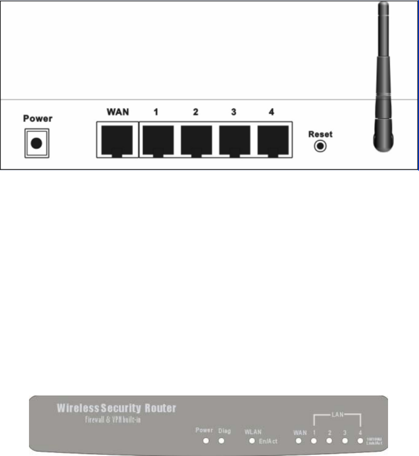
2-1 Rear Panel & Connections
The following figure shows the rear view of the 11g Wireless Security Router and
illustrates how the cables connect to the interfaces on the rear panel.
1. Plug one end of the UTP cable into the WAN port, the other into the RJ45
Ethernet jack on your ADSL or Cable modem.
2. Connect a PC, which must have an Ethernet NIC (Network Interface Card)
installed, to one of the LAN Ports.
3. Connect the external power supply to the 11g Wireless Security Router.
4. The Reset button is used to reboot and re-initialize the device (press once quickly),
or for clearing configuration settings back to factory default values (press for
longer than 3 seconds).
2-2 Front Panel LEDs
The following figure shows the front view of the 11g Wireless Security Router .
The LEDs on the front panel indicate the status of the unit. You can easily view the
operation of your 11g Wireless Security Router from this panel.
11g Wireless Security Router User Guide
- 7 -
Power: Green The Power LED illuminates when the Wireless 11g Router is
powered on.
Diag Red The Diag LED illuminates when Router goes through its
self-diagnosis mode during boot-up. It will turn off upon
successful completion of the diagnostic.
For WLAN
Enable
/Activity: Green The Links LED illuminates when the wireless option is
enabled. When the wireless option is disabled (through the
web-based utility), the LED is off.
Blinking when there is wireless connection activity.
For WAN port & LAN ports (x4)
Green Steady on when a successful 100Mbps connection is made
trough the corresponding port.
Blinking when data is flowing through this port.
Link/Act &
10/100:
Yellow Steady on when a successful 10Mbps connection is made
trough the corresponding port.
Blinking when data is flowing through this port.
2-3 System Requirements and Setup
To connect to the Internet, an external ADSL or Cable modem and an Internet access
account from an ISP is required. In order to operate with the 11g Wireless Security
Router , each PC that is to be connected to the 11g Wireless Security Router should have
the following things installed:
1. Ethernet NIC (Network Interface Card: a 10Base-T or 10/100Base-T/TX
Ethernet card), or wireless client card for wireless connection.
2. Standard twisted-pair Ethernet cable (UTP network cable) with RJ-45
connectors.
3. System OS: Windows 95/98, Windows NT4.0, or Windows 2000/XP
4. TCP/IP network protocol.
5. Web browser, such as Microsoft Internet Explorer 5.0 or later, or Netscape
Navigator 6.0 or later.
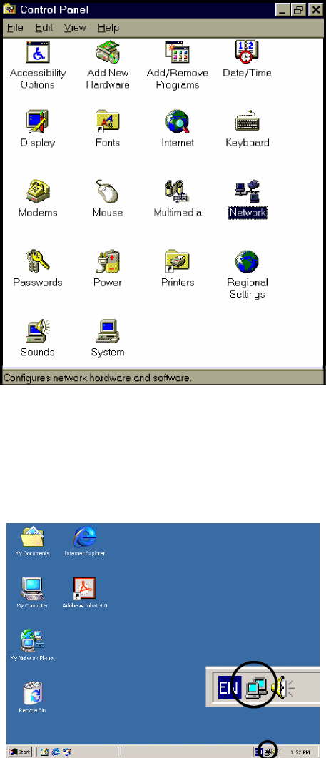
Installing the TCP/IP Protocol
If you are not sure whether the TCP/IP Protocol has been installed, follow these steps to
check, and if necessary, install TCP/IP onto your PCs.
1. Click the “Start” button. Choose “Settings”, then “Control Panel”.
Double-click the “Network” icon. Your Network window should appear.
11g Wireless Security Router User Guide
- 8 -
Select the “Configuration” tab.
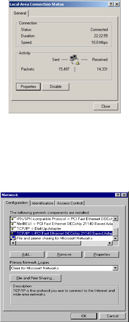
Note: For Windows 2000 & Windows XP Setting
Click the “Local Area Connection” icon on the lower right hand side of
your desktop screen.
In the “Local Area Connection Status” window, click the “Properties”
button then your Network window will appear.
11g Wireless Security Router User Guide
- 9 -
There is only one tab, “General”, in the Network window.
2. Check whether the TCP/IP Protocol has already been installed onto your
computer’s Ethernet card. Note that TCP/IP Protocol can be installed for a
computer’s Dial-Up Adapter as well as for the Ethernet card.
- If yes, go to step 7.
- If no, click the “Add” button.
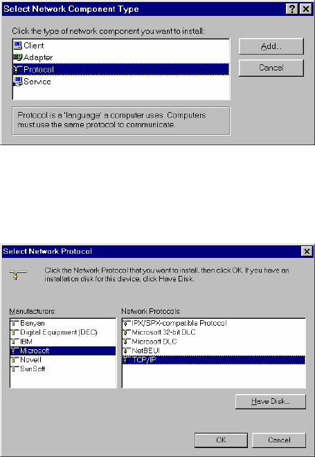
3. Double-click “Protocol” in the Select Network Component Type or
highlight “Protocol” then click “Add”.
11g Wireless Security Router User Guide
- 10 -
4. Highlight “Microsoft” under the list of manufacturers.
Double-click “TCP/IP” from the list on the right or highlight “TCP/IP”
then click “OK” to install TCP/IP.
5. After a few seconds, you will be returned to the Network window. The
TCP/IP Protocol should now be on the list of installed network components
(see 2 above).
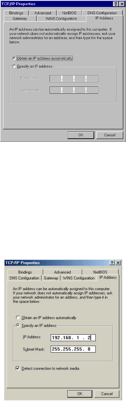
6. Click the “Properties” button.
The TCP/IP Properties window consists of several tabs. Choose the “IP
Address” tab.
7. Select “Obtain an IP address automatically”. Click “OK”. Restart your
PC to complete the TCP/IP installation.
11g Wireless Security Router User Guide
- 11 -
Fixed IP Addresses Configuration
Fixed IP addresses may be assigned to network devices for many reasons, such as the
server PCs or printers which are consistently accessed by multiple users. To set up
computers with fixed IP Addresses, go to the “IP Address” tab of the “TCP/IP
Properties” window as shown above.
Select “Specify an IP address” and enter “192.168.1.***” in the “IP Address” location
(where *** is a number between 2 and 254 used by the 11g Wireless Security Router to
identify each computer), and the default “Subnet Mask” 255.255.255.0”. Note that no
two computer on the same LAN can have the same IP address.
11g Wireless Security Router User Guide
- 12 -
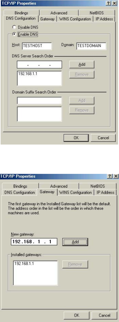
Click on the “DNS Configuration” tab and select “Enable DNS”. Enter the “DNS IP
Address” obtained from your ISP in the “Server Search Order” location. Then click
the “Add” button.
Click on the “Gateway” tab and enter the 11g Wireless Security Router ’s default
gateway value 192.168.1.1 in the “New gateway” field, then click “Add” Botton.
Click “OK”. Restart your PC to complete the TCP/IP installation.

11g Wireless Security Router User Guide
- 13 -
Chapter 3: Internet Access
This chapter describes the procedures necessary to configure the basic functions and
begin using your 11g Wireless Security Router . If you follow these procedures correctly,
there should be no problem in accessing the Internet via your 11g Wireless Security
Router .
3-1 Prepare your network information
In order to allow quick referencing when setting up your 11g Wireless Security Router , it
is suggested you complete the table below with the necessary information. This should be
supplied by your ISP.
Provided by some ISPs Host Name:
Domain Name:
IP address given by ISP: | Obtain IP Address automatically
| Static IP
IP Address:
. . .
Subnet Mask:
. . .
Default Gateway:
. . .
DNS Server Primary:
. . .
DNS Server Secondary:
. . .
DNS Server Third:
. . .
PPP authentication: | PPPoE
| PPTP
Login Name:
Password: ________________
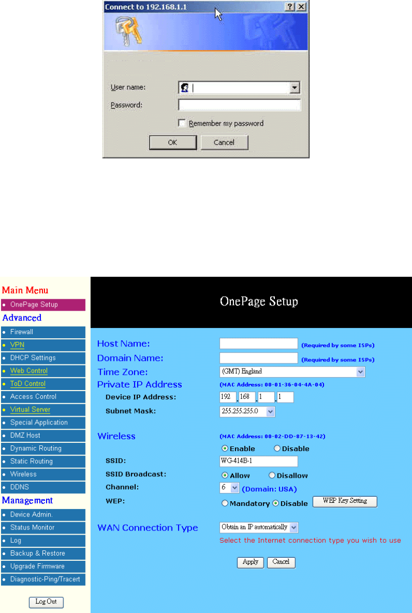
3-2 Web-based User Interface
Your 11g Wireless Security Router is designed to use a Web-based User Interface for
configuration. Open your web browser and type http://192.168.1.1 in the browser’s
address box. This address is the factory set IP Address of your 11g Wireless Security
Router . Press “Enter”.
The “Username and Password Required” prompt box will appear. Leave the
Username field empty and type “admin” (default password) in the Password field. Click
“OK”. The setup screen will then appear.
11g Wireless Security Router User Guide
- 14 -
3-3 Initial Configuration – Setup
The “OnePage Setup” screen is the first screen you will see when you access the Utility.
If the router has already been successfully installed and set up, this screen’s values will
already be properly configured.
Host Name: This entry is required by certain ISPs.
Domain Name: This entry is required by certain ISPs.
Time Zone: Select the time zone of your location from the drop down list.
11g Wireless Security Router User Guide
- 15 -
Private IP Address: The “Device IP Address” and “Subnet Mask” of the router are
used for the internal LAN. The default values are 192.168.1.1 for
the IP Address and 255.255.255.0 for the Subnet Mask.
Wireless: Check “Enable” or “Disable” to make the wireless LAN
function active or inactive.
SSID: As the acronym for Service Set Identifier, SSID is the
unique name shared among all clients and Wireless Security
Router in a same wireless network. The SSID must be
identical for all points and must not exceed 32 characters.
SSID Broadcast: Router will broadcast the SSID to let WLANs clients easily
search and connect to this wireless router by leaving this
item as default setting “Allow”. Click “Disallow” to disable
the broadcast.
Channel: Select the appropriate channel number from the drop-down.
The permissible channels are different from Regulatory
Domains. Make sure that all nodes in the same wireless
LAN network use the same channel, or the channel usage is
automatic when a connection between client and access
point are made.
WEP: As the acronym for Wired Equivalent Privacy, WEP is an
encryption mechanism used to protect your wireless data
communications. WEP uses a combination of
64-bit/128-bit keys to encrypt data that is transmitted
between all points in a wireless network to insure data
security. To code/decode the data transmission, all points
must use the identical key. To make the WEP encryption
active or inactive, select “Mandatory” or “Disable”.
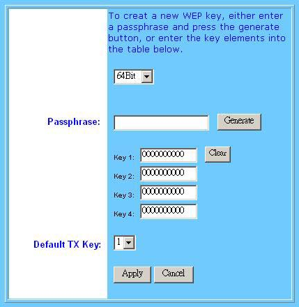
WEP Key Setting: As the WEP is active, click the button of “WEP Key
Setting” to go to the setting page. Select “64Bit” or
“128Bit” encryption algorithm from the drop-down list.
There are two ways to generate WEP key:
1. Passphrase: Enter a alphanumeric text string in this
column then click “Generate” button, and four 64-
b
it
or 128-bit encryption key will be created
automatically.
2. You can enter the WEP key manually.
You may need to enter the WEP key manually in case to
join the existing wireless network. However, if not, the Pass
phrase method is recommended. If you are not sure which
way to use, check with your network administrator.
11g Wireless Security Router User Guide
- 16 -
Default TX Key: Select one of the four keys to be the encryption key you are
going to use in the wireless network. To be sure that all the
points in a same wireless network have to have the same
encryption key.
Click “Apply” after making any changes.
WAN Connection Type:
There are four options for WAN connection types, Obtain IP automatically, Static IP,
PPPoE, and PPTP.
The connection type you need to choose is dependent upon the settings assigned by
your ISP. Which connection type you need to choose may differ from ISPs as well as the
service you applied for. It depends on your ISP’s assignment. If you are unsure which
connection type you currently use, contact your ISP to obtain the correct information.
Obtain IP automatically
It is the default option for the router. If your ISP automatically assign a IP address and
other values to the 11g Wireless Security Router , leave them there without making any
changes.
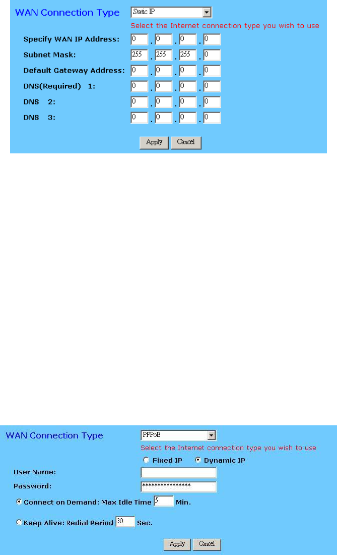
Static IP
The Public IP Address and Subnet Mask of the router are used by external users of the
Internet (including your ISP). If your ISP assigned a fixed IP address, select this item and
enter the IP Address and Subnet Mask provided by your ISP.
11g Wireless Security Router User Guide
- 17 -
Specify WAN IP Address: Enter the IP address provided by your ISP.
Subnet Mask: Enter the subnet mask values provided by your ISP.
Default Gateway IP
Address: Your ISP will provide you with the Default Gateway IP
Address.
Domain Name Server
(DNS): Your ISP will provide you with at least one DNS IP
Address. Multiple DNS IP settings are common. The first
available DNS entry is used in most cases.
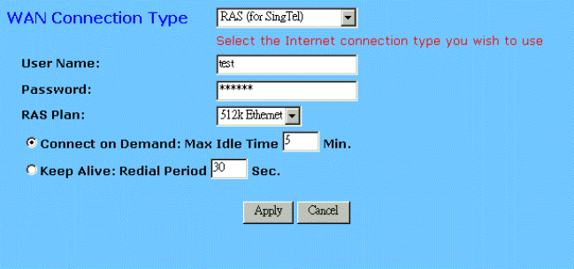
PPPoE
PPPoE is a dial-up connection type provided by some ISPs. It is a cost–effective way for
a user to access this connection type. If your ISP provides PPPoE connectivity, you
should choose this item from the drop-down list. Note that if you select PPPoE, please
remove any existing PPPoE application on any PCs on your LAN.
User Name: Enter the user name your ISP provides you.
Password: Enter the password your ISP provides you.
Connect-on-demand: It is a utility used to trigger the PPPoE session when there
is a packet being sent through the WAN port while it is on
disconnected situation. Check the radio button to make
this function active, and then you must enter the number
of minutes you wish the network to remain idle before
11g Wireless Security Router User Guide
- 18 -
disconnection occurs in the “Max Idle Time” location.
Keep Alive: This function keeps your PPPoE connection enable even
if it remains idle. However, in some situation, PPPoE
session cannot be established immediately after
disconnection. This is because the system on the ISP’s
site may need a little time to restore itself. You may need
to check with your ISP to obtain detail of how long you
need to wait before re-establish the PPPoE session. Enter
this information in the “Redial Period” field.
RAS(for SingTel)
If your ISP uses RAS to establish the connection, you should select this item and follow
the steps below.
User Name: Enter the user name your ISP provides you.
Password: Enter the password your ISP provides you.
RAS Plan: Choose the connection method that you want to use.
Connect-on-demand: It is a utility used to trigger the RAS session when there is
a packet being sent through the WAN port while it is on
disconnected situation. Check the radio button to make
this function active, and then you must enter the number
of minutes you wish the network to remain idle before
disconnection occurs in the “Max Idle Time” location.
Keep Alive: This function keeps your RAS connection enable even if
it remains idle. However, in some situation, RAS session
cannot be established immediately after disconnection.
This is because the system on the ISP’s site may need a
little time to restore itself. You may need to check with
your ISP to obtain detail of how long you need to wait
before re-establish the RAS session. Enter this
information in the “Redial Period” field.
11g Wireless Security Router User Guide
- 19 -
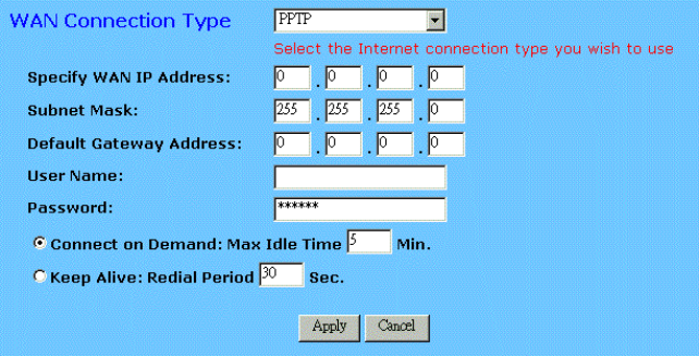
PPTP
PPTP is the acronym of Point to Point Tunneling Protocol. Usually, it is used to
encapsulate other protocols’ packets for transmission over IP network. Some ISPs use
this protocol as way to establish the initial connection between the CPE (end-user side)
and DSLAM (ISP side). If your ISP uses PPTP to establish the connection, you should
select this item and follow the steps below.
Specify WAN IP Address: Enter the IP address provided by your ISP. If your ISP
provides you an Alcatel Speed TouchTM modem, it is
suggested that you enter 10.0.0.150 in this column.
Subnet Mask: Enter the subnet mask values provided by your ISP.
Default Gateway IP
Address: Your ISP will provide you with the Default Gateway IP
Address. If your ISP provides you an Alcatel Speed
TouchTM modem, it is suggested that you enter the
10.0.0.138 in this column.
User Name: Enter the user name provided by your ISP.
Password: Enter the password provided by your ISP.
Connect-on-demand: It is a utility used to trigger the PPTP session when there
is packet being sent through the WAN port while it is on
disconnected situation. Check the radio button to make
this function active, and then you must enter the number
of minutes you wish the network to remain idle before
disconnection occurs in the “Max Idle Time” location.
Keep Alive: This function keeps your PPTP connection enable even if
it remains idle. However, in some situation, PPTP session
cannot be established immediately after disconnection.
This is because the system on the ISP’s site may need a
little time to restore itself. You may need to check with
your ISP to obtain detail of how long you need to wait
before re-establish the PPTP session. Enter this
11g Wireless Security Router User Guide
- 20 -
information in the “Redial Period” field.
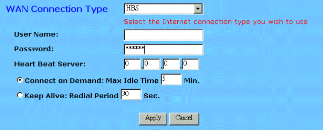
HBS
If your ISP uses HBS to establish the connection, you should select this item and follow
the steps below.
User Name: Enter the user name provided by your ISP.
Password: Enter the password provided by your ISP.
Heart Beat Server: Enter the IP address provided by your ISP. This setting is
available only for some areas. Check your ISP for more
detailed information.
Connect-on-demand: It is a utility used to trigger the HBS session when there is
packet being sent through the WAN port while it is on
disconnected situation. Check the radio button to make
this function active, and then you must enter the number
of minutes you wish the network to remain idle before
disconnection occurs in the “Max Idle Time” location.
Keep Alive: This function keeps your HBS connection enable even if
it remains idle. However, in some situation, HBS session
cannot be established immediately after disconnection.
This is because the system on the ISP’s site may need a
little time to restore itself. You may need to check with
your ISP to obtain detail of how long you need to wait
before re-establish the HBS session. Enter this
information in the “Redial Period” field.
When you have properly configured the Setup page, click “Apply”. You can now test to
see if the settings are all correct by attempting to connect to the Internet.
11g Wireless Security Router User Guide
- 21 -
Chapter 4: Advanced Applications
This chapter provides information on how to set up and use the advanced functions of
your 11g Wireless Security Router .
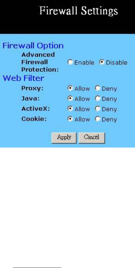
4-1 Firewall
The settings page allows you to configure advanced Firewall functions, providing
superior security for your network environment.
Firewall Option: Enabling this function will prevent DoS (Denial of Service)
attacks and activates the SPI (Stateful Packet Inspection). The
SPI function will check any incoming data packets, particularly
whenever there is a TCP connection initiated by your LAN PCs.
Web Filter: This feature provides options allowing you to filter any
potential risk contained in some web technologies by
individually checking “Allow” or “Deny”.
Web proxy is a server your device will connect to when you
access any web site. Setting web proxy can speed up access
time but also can create other potential security issue. For
example, if you configure the Wireless Security Router to block
access to 216.115.102.76, which is the IP address of
www.yahoo.com, it will fail. This is because your PC will
connect to web proxy server instead of connecting to Yahoo’s IP
address.
Java & Active X are programming languages for web page.
However, some potentially harmful Trojan programs and
11g Wireless Security Router User Guide
- 22 -
viruses are also written in these languages. If you deny access to
either of these, you may run the risk of not having access to
certain web pages.
A cookie is a small piece of data (usually in the form of a text
file), which is stored on your PC when you visit certain web
sites. This allows the server to identify your machine at a future
date. The cookie normally contains an ID number but can also
contain other information.
Apply: Click this button after making any changes for activating the
settings.
Cancel: Click this button if you are not satisfied with the settings in this
page before clicking Apply.
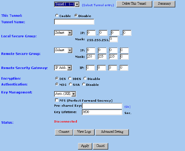
4-2 VPN Settings
This page allows you to set configuration for Virtual Private Network. Please choose
Advanced – VPN to get into the following screen.
Select Tunnel Entry: When you wish to establish a “Tunnel” to transfer security data
or information between specific points, you must first select a
“Tunnel” number from the drop-down box. This will allow you
to identify the setting of each individual tunnel.
This Tunnel: Check “Enable” on the next column to activate the tunnel.
Tunnel Name: Once the tunnel is enabled, you should enter the name of the
tunnel in this field. This allows you to differentiate a new tunnel
11g Wireless Security Router User Guide
- 23 -
from any others you have created.
Note: The tunnel name set here does not always have to match
the name used at the other end of the tunnel. However, certain
VPN applications require a tunnel to have the same name at
both ends of the tunnel. If the other end point with which you
want to establish the tunnel dose not use this Wireless Security
Router, it is important that you give the other side precise set
up instructions and ensure that these are followed.
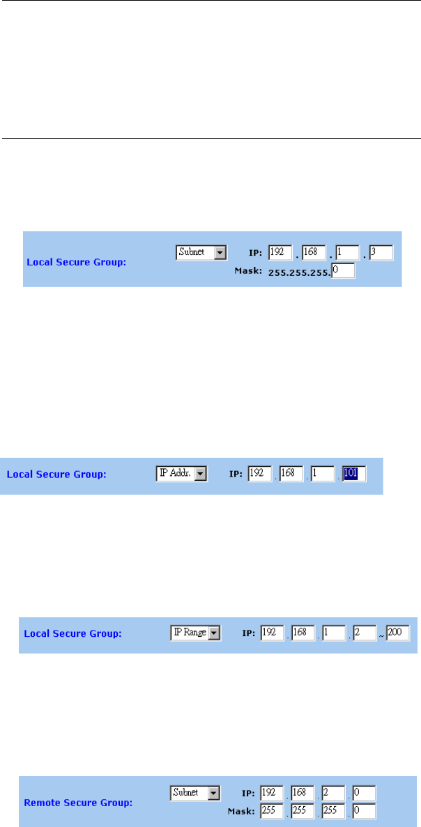
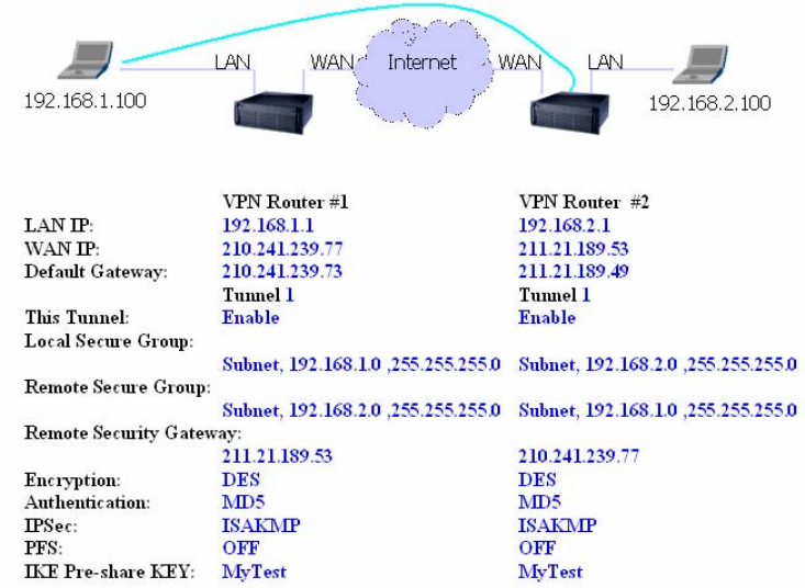
Local Secure Group: There are some options that you can choose for this item:
(1) Subnet
Select this item to allow all the PCs on the LAN side access
to the tunnel.
Refer to the above figure as an example. All Local Secure
Group computers with IP Addresses 192.168.1.xxx will be
able to access the tunnel. When the Subnet setting is
selected, the default values of 0 should remain in the IP and
Mask fields.
(2) IP Address
8. Selecting this item allows only the specific
PC with the IP address you enter in the IP field to the tunnel.
Refer to the above figure as an example. Only the PC with IP
Address 192.168.1.101 will have the access from the local side
of tunnel.
(3) IP Range
Selecting this item allows a specific group of PCs access to
the tunnel.
Refer to the above figure as an example. Only the PCs with
the IP addresses between 192.168.1.2 and 192.168.1.200
can access the local side of the tunnel.
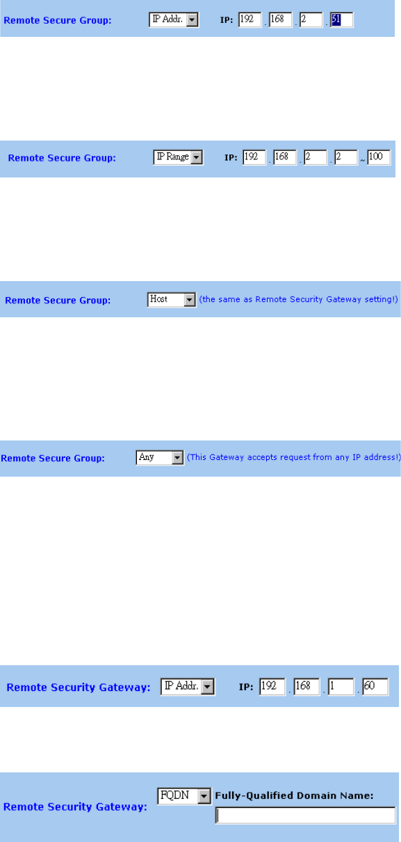
Remote Secure Group: (1) Subnet
Select this item to allow all the PCs on the LAN side access
to the tunnel.
All Remote Secure Group computers with IP Addresses
192.168.2.xxx will be able to access the tunnel. When the
Subnet setting is selected, the default values of 0 should
11g Wireless Security Router User Guide
- 24 -
remain in the IP and Mask fields.
(2) IP Address
Selecting this item allows only the specific PC with the IP
address you enter in the IP field to the tunnel.
Only the PC with IP Address 192.168.2.51 can access the
tunnel from the other end.
(3) IP Range
Selecting this item allows a specific group of PCs access to
the tunnel.
PCs with IP Address between 192.168.2.2 and
192.168.2.100 can access the tunnel from the other end.
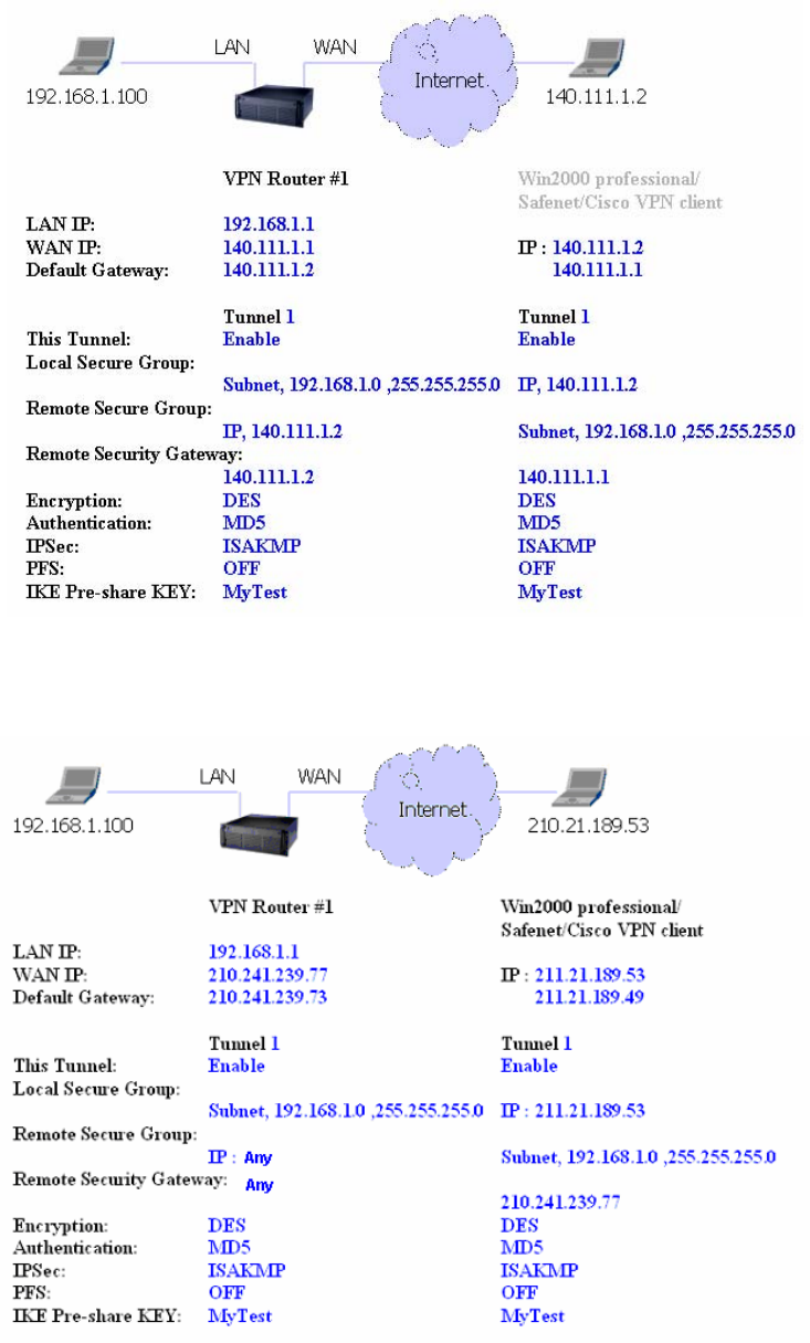
(4) Host
If you select “Host”, the value set here should be the same as
the Remote Security Gateway setting.
(5) Any
When this option is selected, the Router accepts remote
requests from any IP address, such as mobile users or
telecommunications device using dynamic IP address. Note
that the router cannot initial VPN connection when “Any” is
selected as Remote Security Group.
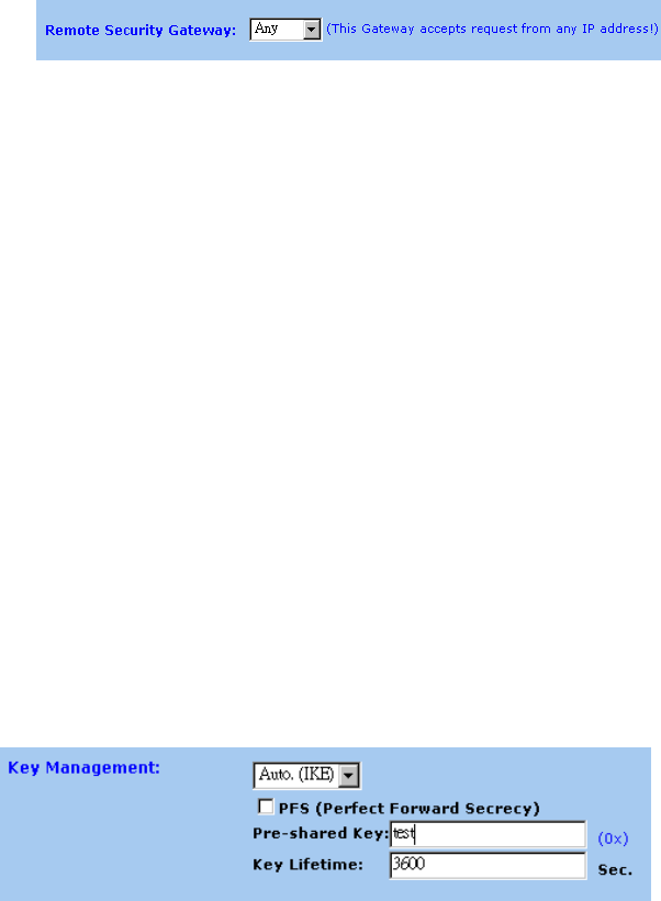
Remote Security
Gateway: Define the end point of VPN tunnel in the other side. The
remote VPN tunnel end point can be another VPN Router, a
VPN Server, or a host with VPN software. For example, if the
VPN device at the other end of the tunnel is a VPN router, enter
the WAN IP Address of that VPN router in this section. For
more detail, refer to the description of “Example - establish
the VPN connection” on next few pages.
(1) IP Address
Use IP Address to identify the remote VPN tunnel end point.
(2) FQDN
Use domain name to identify the remote VPN tunnel end
point.
11g Wireless Security Router User Guide
- 25 -
(3) Any
Accept remote requests from any IP address. Note that the
router cannot initial VPN connection when “Any” is
selected.
Encryption: This item helps give your VPN connection added security.
There are two different type of encryption: “DES” or “3DES”.
DES uses 64-bit encryption key, and 3DES uses 128-bit
encryption key. You may choose either of them, but be aware
that both end of a VPN tunnel should use the same encryption
type. You may also choose not to enable encryption by
selecting “Disable”.
Authentication: This item adds another level of security. There are two types of
authentication: “MD5” and “SHA”. You may choose either of
these but, as with encryption, both ends of the VPN tunnel
should use the same authentication type. You may also
choose not to use the authentication function by selecting
“Disable”.
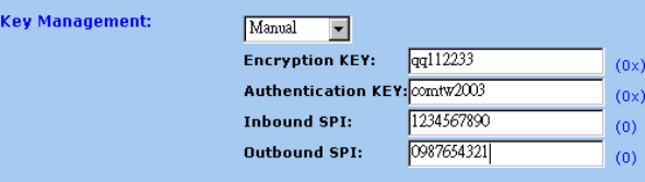
Key Management: In addition to use the same encryption type, both side of VPN
tunnel should also share the same encryption “Key”. This is
necessary for proper encryption security and allows the
encryption to function correctly. By using the Key
Management drop down list, you can choose two of two
methods to set the Encryption Key: “key”: Auto (IKE) or
Manual.
Auto (IKE):
With Auto (IKE), you must enter a series of characters in the
“Pre-shared Key” field. In the example shown in the figure
above, the word Test has been used. The program will
automatically generate the correct codes to be used in the
encryption and authentication basing on the word you entered.
You may use any combination of up to 23 alphanumeric
characters in this field. No special characters or spaces are
allowed.
By entering the number of seconds in the Key Lifetime field,
you may optionally select to have the key expire at the end of
the time you specify. Leave this field blank for the key to last
indefinitely.
Manual
11g Wireless Security Router User Guide
- 26 -
Manual keying allows you to manually enter the keys to be
used for encryption and authentication. Enter the Keys (code)
you wish to use for encryption and authentication separately in
the “Encryption KEY” and “Authentication KEY” fields. Up
to 23 alphanumeric characters are allowed in each field. Be
aware that both ends of the VPN tunnel should use the same ke
y
management method in addition to same encryption and
authentication keys.
The “Inbound SPI” value set here must match the Outbound
SPI value at the other end of the VPN tunnel. Conversely, the
“Outbound SPI” must match the Inbound SPI value at the
other end. Only numeric characters can be used in both these
fields.
Status and Connect: After finalizing the settings at both ends of the VPN tunnel,
click the “Connect” button to initiate the VPN tunnel. Once a
connection is established, the word “Connected” should
appear under “Status” if the connection is successful. Should
the word “Disconnected” appear, it is an indication that a
problem exists, preventing the successful creation of the tunnel.
In this case, you should firstly ensure that your wiring is surely
connected. Next, double-check that correct values have been
entered in the VPN configuration screen. Lastly, ensure that the
settings at the other end of the tunnel are correct as well.
View Logs: This window briefly shows the system log, access log, firewall
log and VPN log. Before clicking this button to view the results,
please enable Log from Management item first.
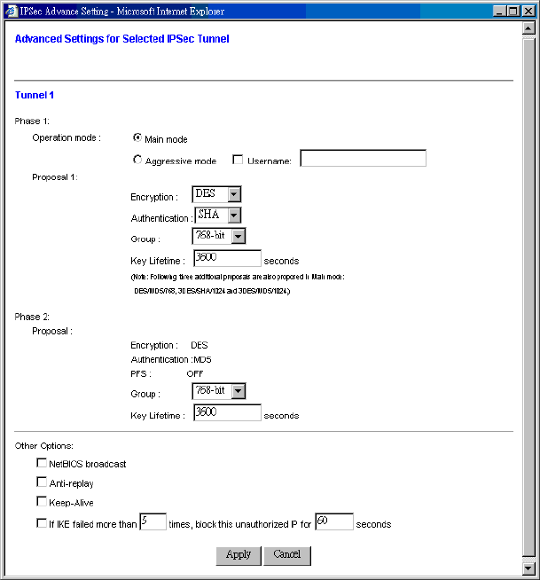
Advanced Setting: To establish a VPN tunnel with another providers’ VPN
solution, configuration of the advanced setting is sometimes
necessary. Click the “Advanced Setting” button and the screen
shown below will appear.
11g Wireless Security Router User Guide
- 27 -
Operation mode:
There two options in this mode: Main and Aggressive. Main
mode is the default and is more secure method. Aggressive mode
is used when the devices at the remote end of the VPN tunnel use
Aggressive mode. Mostly, it is used with dynamic IP addresses.
Whenever the Main or Aggressive modes are selected, the router
will accept both modes initialed by the remote VPN devices.
Encryption:
Select either DES or 3DES from the drop down list. 3DES is
default as it is the more secure option.
Authentication:
Select either MD5 or SHA from the drop down list. SHA default
as it is the more secure option.
Group:
Two Diffie-Hellman Groups can be selected from the drop down
list: 768-bit and 1024-bit. Diffie-Hellman is a technique that uses
public and private key for encryption and decryption.
Key Lifetime:
You may optionally select to have the key expire after a period
of time that you specify. Enter the number of seconds you’d like
the key to be available or leave the field
b
lank for the key to last
indefinitely.
11g Wireless Security Router User Guide
- 28 -
NetBIOS Broadcast:
Check the box to allow NetBIOS traffic pass through the VPN
tunnel.
Anti-replay:
Check the box to enable this function. This item will keep track
of sequence numbers as data packets arrive and ensure security
at the IP packet level.
Keep-Alive:
Check the box to re-establish the VPN tunnel connection
whenever it is dropped. After the tunnel has been created, this
function will keep the connection alive for a period of time.
Unauthorized IP Blocking:
Check the box will allows to block unauthorized IP addresses for
a specified period of time after a specific number of IKE failures.
Entered the time period and failure level in the fields indicated.
Apply Click this button after making any changes for activating the
settings.
Cancel Click this button to exit the screen without saving any changes.
Examples - Establishing the VPN connection
Here we provide 3 examples for establishing a VPN connection.
¾ Creating a tunnel between two VPN routers
¾ Creating a tunnel between VPN router and VPN client with fix IP Address
11g Wireless Security Router User Guide
- 29 -
¾ Creating a tunnel between VPN router and VPN client with dynamic IP
Address
Once you are satisfied that your settings are correct, click the “Apply” button.
Click the “Cancel” button to exit the screen without saving any changes.
11g Wireless Security Router User Guide
- 30 -
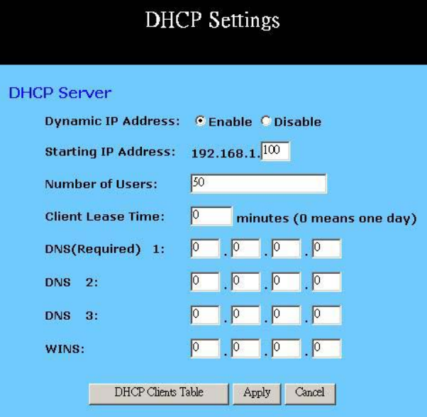
4-3 DHCP Configuration
A DHCP (Dynamic Host Configuration Protocol) Server can automatically assign IP
Addresses to each computer in your network. Unless you already have one in you LAN, it
is highly recommended that you set your router to act as a DHCP server.
Dynamic IP Address: Select “Enable” to use the DHCP server option of the router.
If you already have a DHCP server in your network, set the
router's DHCP option to “Disable”.
Starting IP Address: Enter a numerical value, from 2 to 254, for the DHCP server to
start at when assigning IP Addresses.
Number of Users: Enter the maximum number of PCs that you want the DHCP
server to assign IP Addresses to, with the absolute maximum
being 253.
Client Lease Time: Enter the number of time that DHCP clients (The PCs on LAN
side) can use the IP Addresses assigned by Router’s DHCP
server. Before the time is up, DHCP clients have to request to
renew the DHCP information.
DNS: The IP Address of the Domain Name Server, which is
currently used. Multiple DNS IP settings are common. The
first DNS entry will be use in most cases.
WINS: Windows Internet Naming Service converts NETBIOS name
to IP address. The Windows based PCs are assigned
NETBIOS names, which have to be transfer into IP addresses
11g Wireless Security Router User Guide
- 31 -
if the network transport is TCP/IP. For example, through
WINS the two PCs that belong to different subnet can locate
each other by name. Enter the IP address of WINS server and
it will be assigned to DHCP clients.
DHCP Clients Table Click the DHCP Clients Table button to show current DHCP
client information.
Apply Click this button after making any changes for activating the
settings.
Cancel Click this button if you are not satisfied with the settings in
this page before clicking Apply.
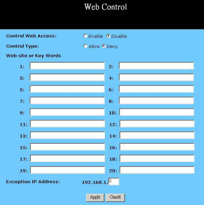
4-4 Web Control
This feature allows you to restrict LAN users access to specific web sites. To block a site,
you can enter either a complete URL (Internet address) or keywords included in the URL.
Control Web Access: Check “Enable” or “Disable” to make this function active or
inactive.
Control Type: Check “Allow” to allow users on the network to access
11g Wireless Security Router User Guide
- 32 -
specific website listed on the location only. In contrast, to
restrict users on the network to access the website listed on the
location, check “Block” in this item.
Web site or Key Words: Enter either a complete URL (Internet address) or keywords
included in the URL.
Exception IP Address: Enter the IP Address of LAN PC that will not be restricted by
this rule.
Apply Click this button after making any changes for activating the
settings.
Cancel Click this button if you are not satisfied with the settings in
this page before clicking Apply.
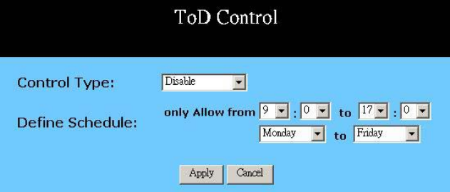
4-5 ToD Control
This feature allows you to limit connection availability according to a nominated time
schedule.
Control Type: Select the control type from the drop down list and make this
function active. Select “Block Outbound” to restrict the
connection to the Internet from your LAN. Select “Block
Inbound” to restrict any external connections from Internet to
your LAN servers that were set as virtual servers or as DMZ
host. Select “Block Both” to restrict both incoming and
outgoing connections. Select “Disable” to turn off this
function.
Define Schedule: Set a period of time with beginning and ending from the drop
down list.
Apply Click this button after making any changes for activating the
settings.
Cancel Click this button if you are not satisfied with the settings in
this page before clicking Apply.
11g Wireless Security Router User Guide
- 33 -
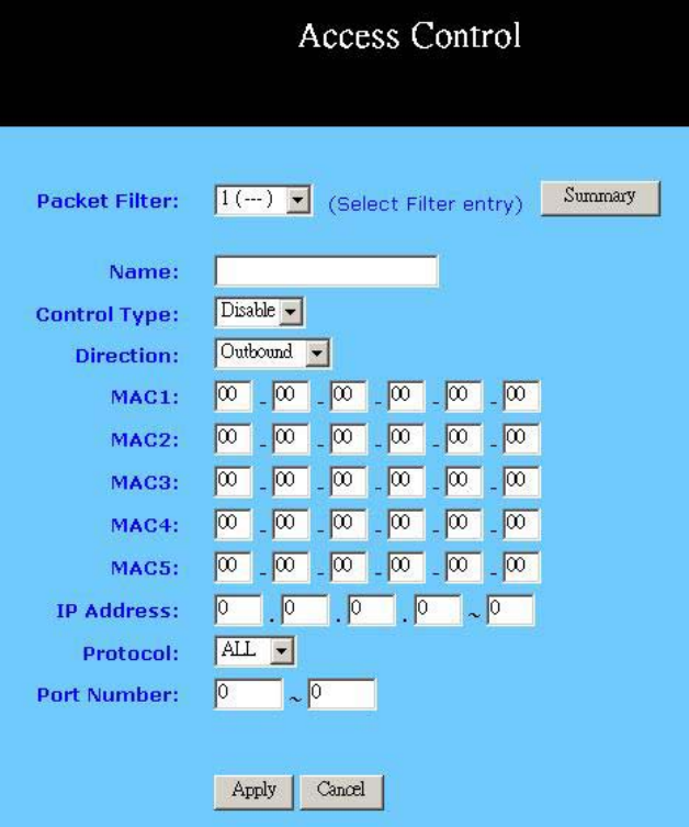
4-6 Access Control
The Access Control feature allows administrators to set up to 20 access policies to block
or allow certain users from accessing the Internet or specific applications. Before using
this function, the network PCs which you want to control the access limitation should be
assigned fixed IP Addresses.
Packet Filter: Select the number of policy rules you want to configure. There
are up to 20 rules you can set. Note that these rules are
sequencied. Rule 1 has higher priority than Rule 2 and so
forth.
Name: For each rule, you can enter up to 15 characters to identify it.
Control Type: Select “Allow” to limit users/computers access to specific
applications you set on this rule. Select “Deny” to restrict the
users/computers access to specific applications you set on this
rule.
Direction: Choose the initial network data traffic direction you wish to
block. Select “Outbound” to restrict the connection to the
Internet from your LAN. Select “Inbound” to restrict any

11g Wireless Security Router User Guide
- 34 -
external connections from Internet to your LAN.
MAC: This item allows network administrators to use the MAC
addresses of PCs to restrict users/computers from accessing
the specific application you set in this rule. A MAC address is
short for Media Access Control Address and is a hardware
address that uniquely identifies each node on network. Enter
the MAC addresses of the computers you wish to allow/block
in each field.
IP Address: This item allows network administrators to use IP Address of
PCs to restrict users/computers from accessing the certain
applications you set in this rule. Enter the range of IP
addresses if you want them to be included in a controlled
group with the same access limitation
Note that if you set both “MAC” and “IP Address” in one rule,
the PCs which have the MAC addresses matching in “MAC”
field and their IP addresses matching in the “IP Address” field
will be allowed/blocked for certain applications.
Protocol: Select the protocol type as “ICMP”, “TCP” or “UDP” from
the drop down list. If you are not sure which one to choose,
select “All”.
Port Number: Enter the range of port numbers that are used by the
applications you wish to be blocked. For example, port 80
usually is used as destination port number when you access a
web page. Note that if you don’t enter any value in the
“MAC” and “IP Address” column but enter the port number,
for example “80”, in this field, it means all the users/PCs will
be allowed/denied access to certain applications related to this
port, for example “web browsing”.
Summary Click this button to display a summary page showing all the
current rules you have set.
Apply Click this button after making any changes for activating the
settings.
Cancel Click this button to exit the screen without saving any
changes.
Here is a sample of Access Control Setting. There is a PC you wish to block in your LAN
side with MAC address like 00-01-36-02-B1-4F, and an IP Address 192.168.1.101.
Ether the PC’s MAC address in the “MAC” field or the IP address included in the “IP
Address” range that covers this PC’s IP address. Enter the range of 20~80 in the “Port
Number” column, then click the “Apply” button. As a result, this PC with MAC address
00-01-36-02-B1-4F and IP Address 192.168.1.101 will not be able to use the
applications which use port numbers from 20 to 80, such as FTP, Telnet and web
browsing.
11g Wireless Security Router User Guide
- 35 -
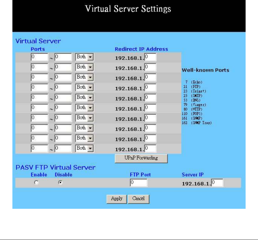
4-7 Virtual Server Settings
The Virtual Server Settings application allows you to set up a maximum of ten public
services that can be accessed by external users of the Internet, such as a Web Address,
Email, FTP etc.. Each service is provided by a dedicated network computer (server)
configured with a fixed IP Address. Although the internal service addresses are not
directly accessible to the external user, the Wireless Security Router is able to identify the
service requested by the service port number and redirects the request to the appropriate
internal IP Address/server. To use this application, it is recommended you use a fixed
Public IP Address from your ISP. Note that your Wireless Security Router supports only
one server of any particular type.
This router also support UPnP Forwarding. You can use either Virtual Server Settings or
UPnP Forwarding by clicking the button to change setting page. Please note that do not
set the same function server to different IP Address in different setting pages.
Set up individual network computers to act as servers and configure each with a fixed IP
Address.
Note: In the “One Page Setup” screen, ensure the “Private IP Address” is set to the
Wireless Security Router’s default setting of 192.168.1.1. If a fixed Public IP Address is

11g Wireless Security Router User Guide
- 36 -
to be used, select “Specify an IP address” and enter the IP Address and other necessary
information provided by your ISP.
Ports: Enter the desired service port numbers in the “Ports” fields.
You can specify the protocol type as “TCP” or “UDP” from
the drop-down list. If you are not sure which one to select,
choose “Both”. A selection of well-known service port
numbers is provided on this screen.
Redirect IP Address: Enter the appropriate IP Addresses of the service computers in
the “Redirect IP Address” locations.
Passive FTP Virtual
Server: When there is firewall filtering in your network, the Internet
user may not be able to access FTP server you set in the LAN
side. Setting FTP server at passive mode will be necessary.
Enable/Disable - Click to enable/disable passive FTP
function.
FTP Port - Enter the port number (> 1024) that the FTP server
will use as data connection port number. The client side
should select passive mode and use the same port number
entered here.
Server IP Address - Enter the appropriate IP Addresses of the
service computers.
Apply Click this button after making any changes for activating the
settings.
Cancel Click this button if you are not satisfied with the settings in
this page before clicking Apply.
Example:
If the service port number 80~80 (representing an HTTP web address) is entered in
“Ports” and 192.168.1.100 is entered in “Redirect IP Address”, then all HTTP requests
from external Internet users will be directed to the PC/server with the 192.168.1.100
fixed IP Address.
Below is a list of the protocol and port ranges that are used by some common
applications.
Application Protocol Port Range
FTP Server TCP 21
Half Life UDP 6003, 7002, 27010, 27015, 27025
MSN Messenger TCP
TCP
UDP
UDP
UDP
TCP
6891-6900 (File-send)
1863
1863
5190
6901 (Voice)
6901 (Voice)
11g Wireless Security Router User Guide
- 37 -
PC Anywhere host TCP
UDP 5631
5632
Quake 2 UDP 27910
Quake III UDP 27660 (first player)
"C:\Program Files\Quake III Arena\quake3.exe" +set
net_port 27660
27661 (second player)
Telnet Server TCP 23
Web Server TCP 80
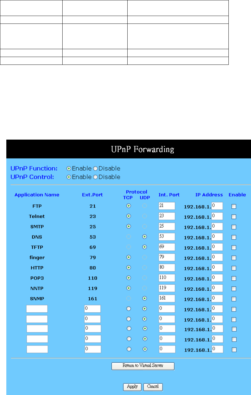
UPnP Forwarding
UPnP (Universal Plug and Play) is a standard introduced from Microsoft and UPnP
Forum for interoperability. Currently, this function supported by this device allows you to
set virtual server from Windows OS that supports UPnP, such as Windows XP.
11g Wireless Security Router User Guide
- 38 -
UPnP Function: Check “Enable” will allow LAN side PCs that support UPnP
to set virtual server.
Before you enable the UPnP Forwarding, you have to set up
individual network computers to act as servers and configure
each with a fixed IP Address.
In the “One Page Setup” screen, ensure the “Private IP
Address” is set to the Router’s default setting of 192.168.1.1.
If a fixed Public IP Address is to be used, select “Specify an
IP address” and enter the IP Address and other necessary
information provided by your ISP.
UPnP Control: Check “Enable” will allow LAN side PCs that support UPnP
to directly configure the settings provided in this page.
Application Name UPnP has ten pre-setting forwarding rules, which are
well-known applications. You can enter any name to present
the additional settings beside those pre-setting rules.
Ext. Port Most of applications usually use their individual port number
for its incoming and outgoing data packets. However, some of
the application may use different port number for incoming
and outgoing data packets. In this case, you have to enter the
port number used by incoming data packets here.
Protocol Specify the protocol type as “TCP” or “UDP” which is used
by specific service.
Int. Ports Most of applications usually use their individual port number
for its incoming and outgoing data packets. However, some of
the application may use different port number for incoming
and outgoing data packets. In this case, you have to enter the
port number used by outgoing data packets here.
IP Address Enter the appropriate IP Addresses of the service computers in
the “Redirect IP Address” locations.
Enable Check to make this forwarding setting active.
Apply Click this button after making any changes for activating the
settings.
Cancel Click this button if you are not satisfied with the settings in
this page before clicking Apply.
Example: If the service port number 80~80 (representing an HTTP web address) is
entered in “Ports” and 192.168.1.100 is entered in “Redirect IP Address”, then all
HTTP requests from external Internet users will be directed to the PC/server with the
192.168.1.100 fixed IP Address.
11g Wireless Security Router User Guide
- 39 -
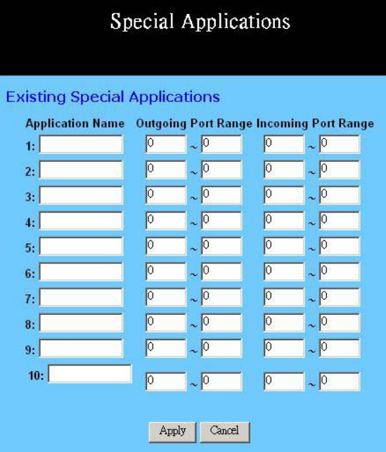
4-8 Special Applications
Some applications use multiple TCP/UDP ports to transmit data. Due to the NAT, these
applications cannot work with the Wireless Security Router. Port Triggering allows some
of these applications to work properly. Note that only one PC can use each Port
Triggering setting at any time.
Application name: Enter the name of application you wish to configure in the
Name column to identify this setting.
Outgoing Port Range: Enter the port number or range numbers this application uses
when it sends packets outbound. The Outgoing Control Port
Numbers act as the trigger. When the Wireless Security Router
detects the outgoing packets with these port numbers, it will
allow the inbound packets with the Incoming Port Numbers
that you set in the next column to pass through the Wireless
Security Router.
Incoming Port Range: Enter the port number or range numbers the inbound packets
carry.
Apply Click this button after making any changes for activating the
settings.

11g Wireless Security Router User Guide
- 40 -
Cancel Click this button if you are not satisfied with the settings in
this page before clicking Apply.
The following is a list of port numbers used on some popular applications:
Application Outgoing Control Incoming Data
Battle.net 6112 6112
DialPad 7175 51200, 51201,51210
ICU II 2019 2000-2038, 2050-2051
2069, 2085,3010-3030
MSN Gaming Zone 47624 2300-2400, 28800-29000
PC to Phone 12053 12120,12122, 24150-24220
Quick Time4 554 6970-6999
wowcall 8000 4000-4020
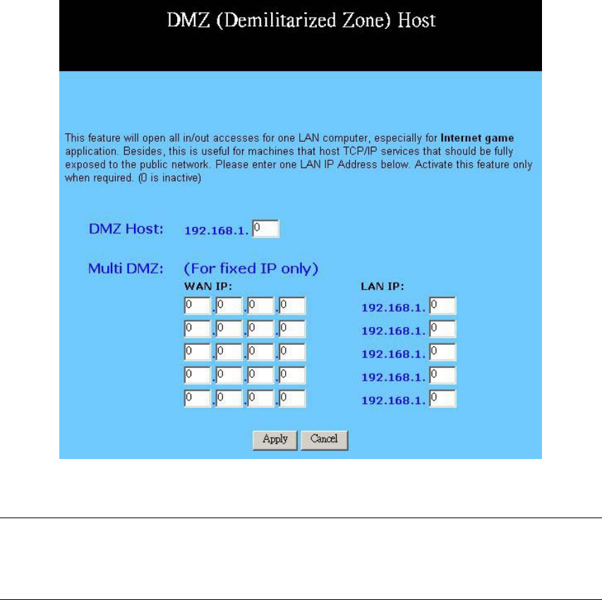
4-9 DMZ Host
The DMZ Host application allows unrestricted 2-way communication between a single
LAN PC and other Internet users or servers. This application is useful for supporting
special-purpose services such as video-conferencing and gaming, that require proprietary
client software and/or 2-way user communication.
To use this application, you must first obtain a fixed Public IP Address from your ISP.
Note that in order to provide unrestricted access, the Firewall provided by the Wireless
Security Router to protect this port is disabled, thus creating a potentially serious security
risk.
It is recommended that this application is disabled when it is not in use by entering “0” in
the “DMZ Host”field.
The Multi DMZ allows you to map the public IP addresses to your LAN PCs, should you
get more than one public IP address from your ISP. This function is useful to set up your
servers, such as an FTP server, web server, and so on, with public IP addresses, but still
keep them within your LAN group.
With the public IP addresses, Internet users will access your servers more easily and
those servers can still communicate with other PCs in you LAN by using Network
Neighborhood.
11g Wireless Security Router User Guide
- 41 -
Before setting up a LAN PC to act as a DMZ Host, you should configure it using a fixed
IP Address.
Note: In the “One Page Setup” screen, ensure the Private IP Address is set to the
Wireless Security Router’s default setting of 192.168.1.1. In the Public IP Address area,
select “Specify an IP Address”, and then enter the IP Address and other necessary
information provided by your ISP.
Click the “DMZ Host” option in the Advanced Menu and enter the fixed IP Address of
the Exposed Host PC in the “DMZ Host” IP Address location. Remember, entering “0”
will disable this application.
Multi DMZ
1. Enter the valid public IP address in “WAN IP” column. Next, enter the private IP
address of the PC that you wish to map to in “LAN IP” field. Up to five public IP
addresses can be entered.
2. Click the “Apply” button after making any changes, or click the “Cancel” button to
exit the screen without saving any changes.
11g Wireless Security Router User Guide
- 42 -
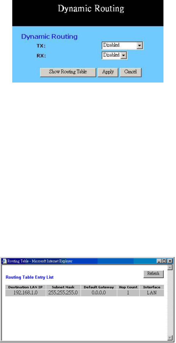
4-10 Dynamic Routing
The Dynamic Routing feature allows your Wireless Security Router to exchange routing
information with other routers in the network. Enabling this feature is likely to enhance
performance of your Wireless Security Router.
TX: From the drop-down list, select one of the routing information
types, “RIP-1”, “RIP-1 Compatible”, or “RIP-2”, to enable
the “TX” (transmit) function. “RIP-1” is the protocol used by
older routers. Newer routers should use “RIP-2”. “RIP-1
Compatible” servers to broadcast RIP-1 and multicast RIP-2.
RX: From the drop-down list, select one of the routing information
types, “RIP-1” or “RIP-2”, to enable the “RX” (receive)
function.
Show Routing Table: Click this button after clicking Apply to see current routing
information.
Apply: Click this button after making any changes for activating the
settings.
Undo: Click this button if you are not satisfied with the settings in
this page before clicking Apply.
Below is Routing Table Entry List. This table shows the status for routing information.
You can click Refresh to update the table information.
11g Wireless Security Router User Guide
- 43 -
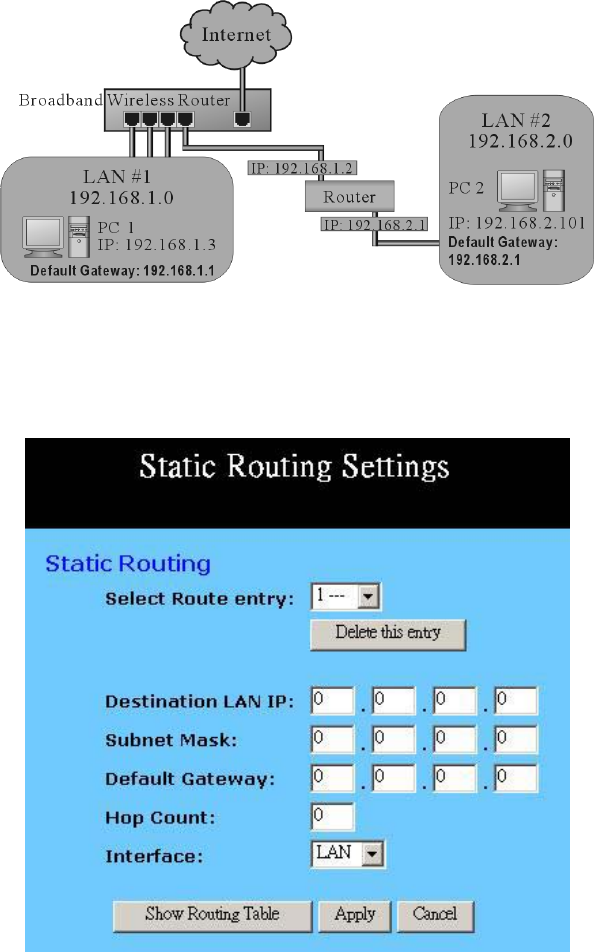
4-11 Static Routing
The Static Routing feature allows PCs that are connected to the Wireless Security Router,
either directly or through a hub/switch (in the immediate LAN), to communicate with
other PCs in the respective LAN segment which are connected to the Wireless Security
Router through another router (destination LAN). Up to 20 route entries may be input
into the Wireless Security Router. The diagram below gives an example of the physical
connections required to use Static Routing.
In the above diagram, PC2 in LAN#2 is connected to the Wireless Security Router via
another router while PC1 in LAN#1 is connected to the Wireless Security Router directly.
Without configuring the Static Routing function, the two PCs would not be able to
communicate with each other.
Select Route entry: Select the route entry number from 1 to 20 that you wish to
configure.
11g Wireless Security Router User Guide
- 44 -
Delete this entry Delete the selected route entry information.
Destination LAN IP and
Subnet Mask: Enter the IP Address and Subnet Mask of the destination LAN
that the immediate LAN is to communicate with. Taking the
above diagram as an example, enter 192.168.2.0 in the
“Destination LAN IP” field and 255.255.255.0 in the
“Subnet Mask” field.
Default Gateway: Enter the IP Address of the router that forwards data packets to
the destination LAN. For the above example, enter
192.168.1.2 in the “Default Gateway” field.
Hop Count: Enter the number of hops required between the LANs to be
connected. The Hop Count represents the “cost” of the routing
transmission. The default value is 1.
Interface: Choose LAN if the Destination LAN is on your Router’s LAN
side and choose WAN if the Destination LAN is on the
Router’s WAN side.
Show Routing Table Click this button after clicking Apply to see current routing
information.
Apply Click this button after making any changes for activating the
settings.
Cancel Click this button if you are not satisfied with the settings in
this page before clicking Apply.
Referring back to the above diagram, with the proper settings, PC1 would be able to
access LAN 1, LAN 2 and the Internet while PC2 can only access LAN 2, LAN1.
4-12 Wireless
This setting page allows you to configure advanced wireless functions. To set those items
needs more technology background. Unless you really understand those technical terms,
it would be better to leave them as default setting.
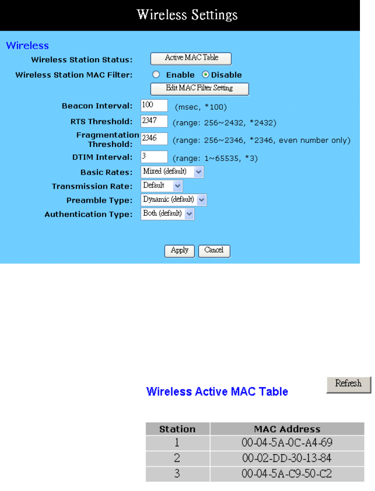
11g Wireless Security Router User Guide
- 45 -
Wireless Station Status: The “Active MAC Table” shows the MAC addresses of
wireless clients, which have the same ESSID and WEP key
with Wireless Security Router. When the “MAC Filter”
function is disabled, the background color is gray.
Click the “Active MAC Table” button will display all MAC
addresses of wireless nodes on your WLAN.
If the MAC Filter function is enabled and the MAC addresses
showing in this table have been entered into the “Edit MAC
Filter” table, the background color of those MAC addresses
will be green. Otherwise, it should be red. If the MAC
addresses have been blocked (check the Filter field beside the
MAC address in Edit MAC Filter table), the background color
will be yellow.
Wireless Station MAC
Filter: This function allows you to restrict wireless users to access
Internet.
Click “Edit MAC Filter Setting” button to open the edit
table.
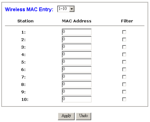
11g Wireless Security Router User Guide
- 46 -
Wireless MAC Entry There are 32 sets divided into four
groups in this function. You can choose each group by
selecting from the pop-down list. Enter the MAC addresses of
the computers you wish to block in the columns and click the
Filter field beside the MAC address, and then that user will be
blocked to link to WLAN and Internet. If the “Filter” field
isn’t checked, that MAC address won’t be blocked. The MAC
address entered here should be 12 continue alphanumeric
digits without “-“ in between. Click “Apply” to save these
changes.
Beacon Interval: It’s the signal sent periodically by wireless access point to
provide synchronization among the stations in wireless LAN.
RTS Threshold: RTS packet is use to account for potential hidden stations.
This feature allows you to set the size of RTS packet.
Fragmentation
Threshold: If the length of data frame needing transmission exceeds the
fragmentation threshold you set in the column, the data frame
will be fragmented. If there is significant interference or high
utilization in your wireless network, the smaller fragmentation
value can increase the reliability transmission. However, it is
more efficient to set the large fragment size.
DTIM Interval: DTIM is the acronym of delivery traffic indication message. It
determines how often the MAC Layer forward multicast
traffic.
Basic Rate: Leave “Mixed” as default setting to compatible with different
wireless standard or select other rates you wish to use to
connect with specific wireless standard devices.
Transmission Rate: Leave “Default” setting or select other speed you wish to use.
Preamble Type: Leave “Dynamic” as default setting or select other type to
compatible with special setting your client devices use.

11g Wireless Security Router User Guide
- 47 -
Authentication Type: Select either Open System or Share Key as authentication
type. If you are not sure, select both.
Apply Click this button after making any changes for activating the
settings.
Cancel Click this button if you are not satisfied with the settings in
this page before clicking Apply.
4-13 DDNS
“DDNS” is an acronym for Dynamic Domain Name Service. Whenerver you set up the
web servers, mail servers, or sometimes ftp servers, you need “Domain Name” to help
Internet users reach your servers easily.
Internet actually runs on IP Addresses which are numerical order, for example
“66.37.215.53”. These IP Address identify the location of each device connected to
Internet. However, the human brain does not easily remember this numbering system, so
a system that allocate domain name such as “www.dyndns.org” provides an easier
method. If you type “66.37.215.53” or “www.dyndns.org” in the web browser’s address
bar, the browser will show the same web page. This is because both methods relate to the
same web server. The “Domain Name Servers” used to manage the Internet will
translate “www.dyndns.org” into the IP Address “66.37.215.53” in order to allow your
browser to find the web server and display the correct web page in your browser.
If your “WAN Connection Type”, as shown in One Page Setup section, is “Obtain IP
Address Automatically”, “PPPoE”, or “PPTP” with dynamic IP address assigned by ISP,
it will cause an error when you set up the public computer servers in your LAN side PCs.
Internet users may not be able to reach your servers because your WAN side IP address
may change each time you initiate the connection to your ISP. The DDNS function will
help to map your IP address to your domain name when your ISP assigns a new dynamic
IP Address.
Note that this DDNS function acts as the client appliance of DDNS service and is only
able to be use in conjunction with the service provided by DynDNS.org. Before you
begin using this function, you will need to apply to DynDNS.org to be able to use the
service. Please visit www.dyndns.org for further information.
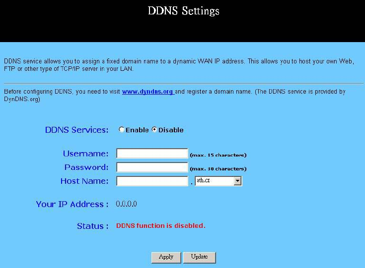
11g Wireless Security Router User Guide
- 48 -
DDNS Service: Check the “Enable” option if you wish to activate this
function.
Username: After you have applied for the DDNS service from
DynDNS.org, you will be issued with a Username. Enter this
username in the “Username” field.
Password: DynDNS.org, will also issue you with a password. Enter the
detail in the “Password” field.
Host Name: DynDNS.org, will provide you with a Host Name. Enter this
name in the “Host Name” field.
Your IP Address It displays the IP Address currently assigned by your ISP.
Status: This displays the current status of the DDNS function.
Apply Click this button after making any changes for activating the
settings.
Update After clicking Apply to invoke the DDNS settings, you have
to click this button to refresh the settings..
11g Wireless Security Router User Guide
- 49 -
Chapter 5: Management
This chapter provides information on using Macintosh computers in your network. The
instructions given here are for system software version 8.0 or above, which comes with
the TCP/IP Protocol preloaded and supports DHCP Addressing.
5-1 Device Administration Settings
This feature allows the administrator to manage the Wireless Security Router by setting
certain parameters. For security reasons, it is strongly recommended that you set
Passwords and so that only authorized persons are able to magage this Wireless Security
Router. If the Password is left blank, all users on your network can access this router
simply by entering the unit’s IP Address into their web browser’s location window.
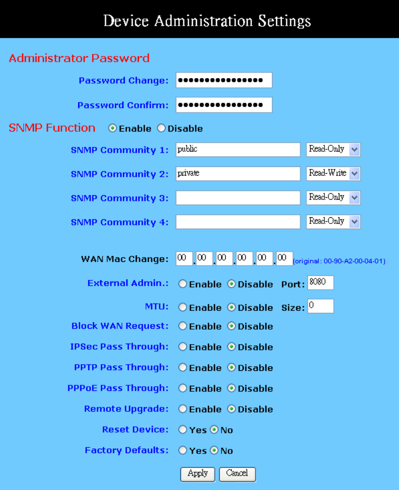
11g Wireless Security Router User Guide
- 50 -
Administrator
Password: Enter the password you want to use into the “Password
Change” field and re-enter it into the “Password Confirm”
field for confirmation. Be sure that the password is less than
64 characters long and without any special characters or
spaces..
SNMP Function: As with the Password, SNMP community allows authorized
persons to access this router through the SNMP Management
tool. The Wireless Security Router provides three fields to
enter these communities. The default words Public and
Private are well-known communities that allow authorized
persons who know the IP Address of this router to access the
11g Wireless Security Router User Guide
- 51 -
read-only information about this router or have the authority
to change the configuration. Also, the administrator can define
any specific community and configure its limits as Read-Only
or Read-Write from the right side drop-down box.
WAN MAC Change: The WAN MAC address can be changed from the original
values if necessary. Some ISPs require users to change the
WAN MAC address to a registered one when users change
their access equipment.
External Admin.: Check “Enable” to allow you to configure the Wireless
Security Router from the WAN side. To access the setting
page from the external side, enter “http://<WAN IP
Address>:8080” into the web browser address bar and press
the “Enter” key.
MTU: Check Enable if you want to set a maximum limitation for
incoming and outgoing packet size. Enter the maximum
packet size you wish to set in the “Size” column.
Block WAN Request: To prevent hacker intruding your network, check the Enable
option to enable this function to reject all the unauthorized
requests from WAN side.
IPSec Pass Through: Check the Enable to allow the IPSec packets to pass through
the Wireless Security Router if there is LAN PC using IPSec
for data communication with other Internet device.
PPTP Pass Through: Check the Enable to allow the PPTP packets to pass through
the Wireless Security Router if there is LAN PC using PPTP
for data communication with other Internet device.
PPPoE Pass Through: Check the Enable to allow the PPPoE packets to pass through
the Wireless Security Router if there is LAN PC using PPPoE
for data communication with other Internet device.
Remote Upgrade: Check Enable if you want to allow the authorized remote
users to upgrade firmware from WAN side.
Reset Device: Select “Yes” if you want to clear a connection, reboot, and
re-initialize the unit without affecting any of your
configuration setting.
Factory Defaults: Select “Yes” if you want to return all the router’s current
settings to their factory defaults. Note that do not restore the
factory defaults unless it is absolutely necessary.
Apply Click this button after making any changes for activating the
settings.
Cancel Click this button if you are not satisfied with the settings in
this page before clicking Apply.
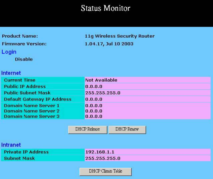
11g Wireless Security Router User Guide
- 52 -
5-2 Status Monitor
This screen shows the router’s current status. All of the information provided is
read-only.
Product Name: This field shows the name of this router.
Firmware Version: This field shows the installed version of the firmware.
Login: This column shows the login information of PPPoE or PPTP.
You can manually initiate the connection or make a
disconnection by clicking the appropriate buttons. Be aware
that, if you make a disconnection here, “Connect-on-
demand” will not function until the connection button is
clicked. Note that “Login” won’t show any information if you
selected “Obtain IP automatically” or “Static IP” on the
OnePage Setup page.
Internet: This section shows the IP settings status of the router as seen
by external users of the Internet. If you selected “Get IP
Address Automatically”, “PPPoE”, or “PPTP” in the
OnePage Setup, the “ IP Address”, “Subnet Mask”,
“Default Gateway”, and “Domain Name Server” (DNS)
will show the information retrieved from the DHCP server or
ISP which is currently being used. If you selected “ Static IP”
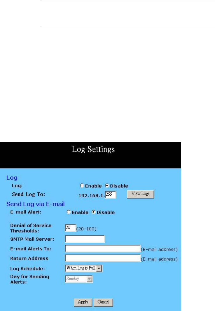
11g Wireless Security Router User Guide
- 53 -
in “One Page Setup: Public IP Address”, the information will
be the same as your input.
DHCP Release: Click this button to eliminate the IP address obtained from
DHCP server.
DHCP Renew: Click this button to refresh the IP address from DHCP server.
Note that the “DHCP Release” and “DHCP Renew” button
only show up when you select “Get IP Address
Automatically” in the OnePage Setup.
Intranet: This section displays the current “Private IP Address” and
“Subnet Mask” of the router, as seen by users of your internal
network.
DHCP Clients Table: If the router is setup to act as a DHCP server, the LAN side IP
Address distribution table will appear by clicking this button.
5-3 Log
The Log application provides the administrator with the ability to trace Internet
connection. With viewing the Log information, an administrator can send the record to a
specific LAN PCs to have the real time monitor.
Log: Check the “Enable” option if you want to activate this
function.
11g Wireless Security Router User Guide
- 54 -
Send Log To: Enter the IP address of the PC that you wish to use to view the
Log information.
View Log: Click this button to view the log on-line.
Send Log via E-mail: The Firewall log can be sent via e-mail.
Denial of Service
Thresholds: The threshold is used to determine the attempt of establishing
connection is DoS attack or not.
SMTP Mail Server: The domain name of IP Address of your ISP’s outgoing e-mail
server. You may find this information when you apply for
e-mail service from your ISP.
E-mail Alert to: Enter the e-mail address you wish to send to.
Return Address: Enter the e-mail address you wish to send to if the alert e-mail
cannot be sent to the address above.
Log Schedule: Select from the drop down list that when you wish the alert
e-mail will be send:
When Log is Full - The alert e-mail will be sent when log
space is full. They are about 30 entries.
Hourly - The alert e-mail will be sent by each hour.
Daily - The alert e-mail will be sent by each day at midnight.
Weekly - The alert e-mail will be sent by each week. When
this item is select.
Day of Sending Alert: When “Weekly” is selected as Log Schedule, you can select
which day in a week to send the alert e-mail.
Apply Click this button after making any changes for activating the
settings.
Cancel Click this button if you are not satisfied with the settings in
this page before clicking “Apply”.
5-4 Backup & Restore
This function allows you to save router’s configuration as backup, or retrieve the
configuration file you saved before to turn the setting back.
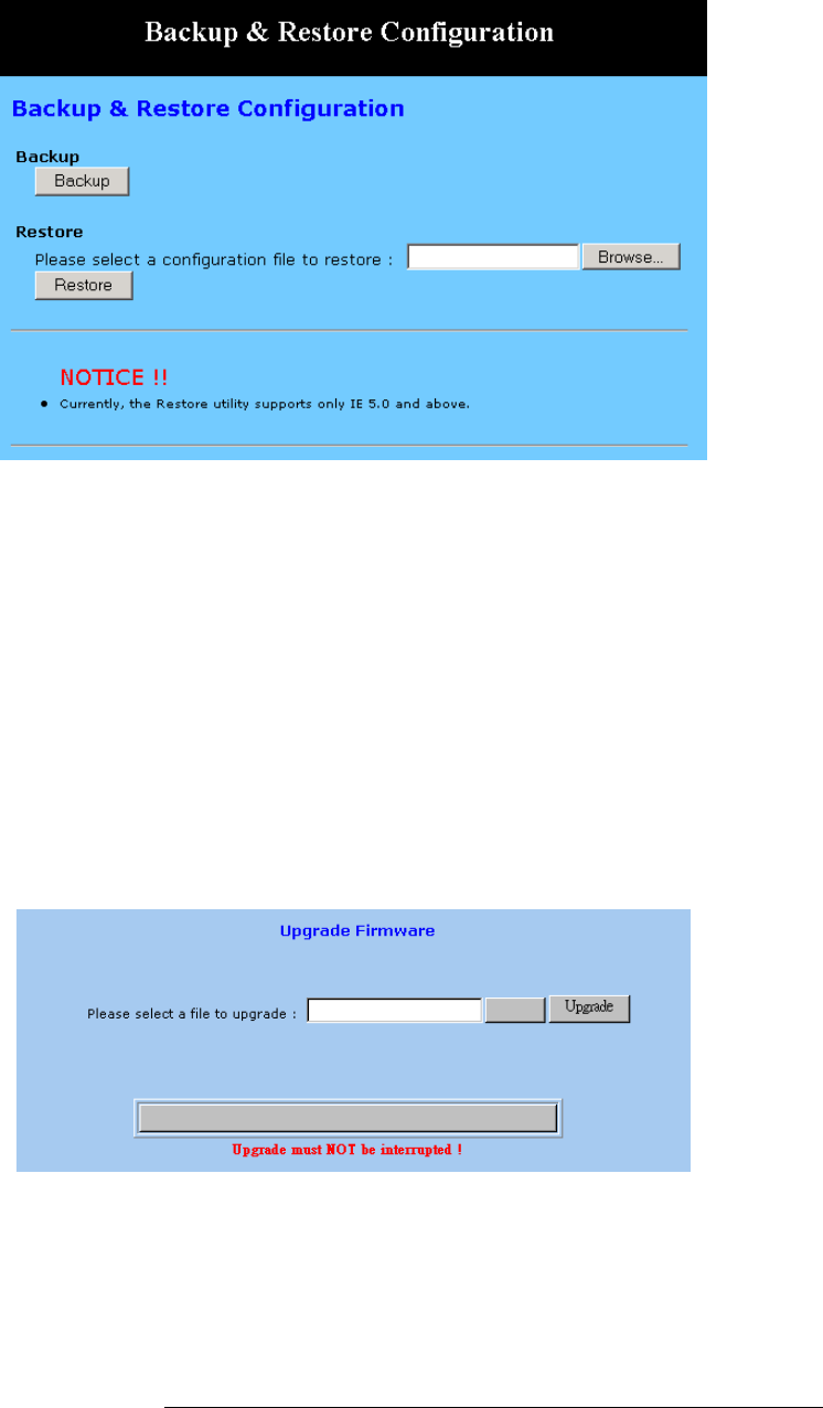
11g Wireless Security Router User Guide
- 55 -
Backup: Click “Backup” button save the current configuration as a
backup file in your hard disk.
Restore: Enter path of the configuration file you saved on the PC. You
can click “Browse” to view the folders and select the file.
Click “Restore” to retrieve it.
5-5 Upgrade Firmware
This setting page allows you to upgrade the latest version firmware to keep your router
up-to-date. Before you upgrade the firmware, you have to get the latest firmware and
save it on the PC you use to configure the router.
Browse..
Browse.. To select a file to upgrade, you have to enter path of the latest
firmware you saved on the PC. You can choose “Browse” to
view the folders and select the firmware.
Upgrade After you enter or select the path, click “Upgrade” to start the
firmware upgrade process.
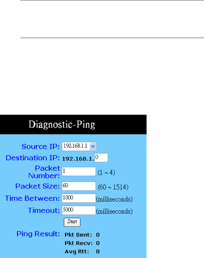
11g Wireless Security Router User Guide
- 56 -
Note that don’t power off the router during the firmware
upgrading, otherwise the incompletion of firmware upgrading
will cause serious damage to the integrity of the router’s
firmware that will lead to fail to boot the router again.
5-6 Diagnostic-Ping/Tracert
This function allows you to test the connection between router and LAN or between
router and Internet.
Ping
Source IP: You can chose to issue the ping test from the LAN side by
selecting Router’s private IP Address or from the WAN side
by selecting Router’s WAN IP Address.
Destination IP: Enter the IP Address of destination device you want to ping. If
Router’s LAN IP address is selected as Source IP, you only
can ping LAN side device and vice versa.
Packet Number: Enter the packet numbers you wish to use to ping the
destination device. The maximum numbers are four.
Packet Size: Enter the numbers of packet size you wish to use to ping the
destination device. The maximum packet sizes are 1514.
Time Between Enter the numbers of time between two packets.
Time out: Enter the number of time regarding as no response after
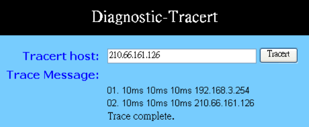
11g Wireless Security Router User Guide
- 57 -
starting to ping the destination device.
Start: Click this button to begin the ping test.
Ping Result: The result will show the numbers of sending packet, numbers
of packet receiving, and the average return time.
Tracert
Tracert Host: Enter the IP Address of destination device that you wish to
trace the route between Router and that device.
Trace Message: The result shows the routing information between Router and
destination device.
Tracert: Click “Tracert” to start this test.
11g Wireless Security Router User Guide
- 58 -
Chapter 6: Macintosh Setup
This chapter provides information on using Macintosh computers in your network. The
instructions given here are for system software version 8.0 or above, which comes with
the TCP/IP Protocol preloaded and supports DHCP Addressing.
6-1 Hardware Connections
Connect your Macintosh computer to your 11g Wireless Security Router . If you have a
newer computer, there will be a Ethernet port on the back. Older computers will need to
have an Ethernet card installed. See your computer’s User’s Manual for instructions on
Ethernet card installation.
6-2 Computer Network Configuration
It is assumed that your computer’s system software already has TCP/IP installed. You
may manually configure your computer with a fixed IP Address or have an IP Address
dynamically assigned to it by the 11g Wireless Security Router ’s DHCP server.
6-2.1 Dynamic IP Addressing using DHCP Server.
1. From the “Apple” menu, select “Control Panel” and click on “TCP/IP”.
2. In the “TCP/IP (A New Name For Your Configuration)” window, select
“Ethernet” in the “Connect via” location from the drop-down list.
3. In the “Setup” area:
- Select “Using DHCP Server” in the “Configure” location from the
drop-down list.
- No other data needs to be entered.
- Close the window.
4. Click “Save” from the file menu, then “Quit” TCP/IP.
5. Restart the computer.
6-2.2 Manual Configuration of Fixed IP Addresses
1. From the “Apple” menu, select “Control Panel” and click on “TCP/IP”.
2. In the “TCP/IP (A New Name For Your Configuration)” window, select
“Ethernet” in the “Connect via” location from the drop-down list.
3. In the “Setup” area:
11g Wireless Security Router User Guide
- 59 -
- Select “Manually” in the “Configure” location from the drop-down
list.
- In the “IP Address” location, enter the IP Address that you want to
assign to the computer. (see the notes on Fixed IP Addresses 2-4 above).
- Enter “255.255.255.0” in the “Subnet Mask” location.
- Enter “192.168.1.1” (the 11g Wireless Security Router ’s default IP
Address) in the “Router Address” location.
- Enter the ISP’s IP Address in the “Name Server” location if your ISP
has provided the information.
- Close the window.
4. Click “Save” from the file menu then “Quit” TCP/IP.
5. Restart the computer.
6-3 11g Wireless Security Router Configuration
To configure your 11g Wireless Security Router , use your Web Browser and follow the
instructions given in Chapter 3: Internet Access, section 3.3. To configure advanced
settings, see Chapter 4: Advanced Applications.
6-4 Adding 11g Wireless Security Router to Existing Network
If the 11g Wireless Security Router is to be added to an existing Macintosh computer
network, the computers will have to be configured to connect to the Internet via the 11g
Wireless Security Router .
1. From the “Apple” menu, select “Control Panel” and click on “TCP/IP”.
2. From the “File” menu, select “Configurations” and select your existing
network configuration. Click “Duplicate”.
3. Rename your existing configuration. Click “OK”, and “Make Active”.
4. In the Setup area:
- Select “Manually” in the “Configure” location from the drop-down
list.
- In the “IP Address” location, enter the IP Address that you want to
assign to the computer. (see the note on fixed IP Addresses 2-4 above).
- Enter “255.255.255.0” in the “Subnet Mask” location.
- Enter “192.168.1.1” (the 11g Wireless Security Router ’s default IP
Address) in the “Router Address” location.
- Enter the ISP’s IP Address in the “Name Server” location if your ISP
11g Wireless Security Router User Guide
- 60 -
has provided the information.
- Close the window.
5. Click “Confirm”. TCP/IP is now configured for manual IP Addressing.
6. Configure your 11g Wireless Security Router (see 5.3 above).

11g Wireless Security Router User Guide
- 61 -
Chapter 7: Trouble Shooting
This chapter provides solutions to problems you may encounter during installation and
operation of your 11g Wireless Security Router .
Hardware
Q: The Power LED is off.
Check that the power cable is properly connected to the 11g Wireless Security Router ,
the power adapter and the socket.
Q: The LAN Link LED is off.
Check that the computer, hub or switch is properly connected to the 11g Wireless
Security Router .
Check that the computer’s Ethernet card is properly installed.
Check that the 11g Wireless Security Router and the computer are on the same network
segment. If you are not sure, initiate the DHCP function (4-1) and set your computer to
obtain an IP address automatically (3-3).
Check that the computer is using an IP address in the range of 192.168.1.2 ~
192.168.1.254 and is therefore compatible with the 11g Wireless Security Router ’s
default IP address of 192.168.1.1 (3-3). Check also the Subnet Mask is set to
255.255.255.0
Q: The DIAG LED stays lit.
The DIAG LED should light up when the device is first powered up to indicate it is
checking for proper operation. After a few seconds, the LED should go off. If it stays lit,
the device is experiencing a problem. Please contact your dealer.
Q: Why can’t I configure the 11g Wireless Security Router ?
First, check whether the 11g Wireless Security Router is properly installed or not,
including the LAN and WAN connections, and that all devices are switched on.
Next, check the IP configuration of your PC:
9 For Windows 95/98 users: run winipcfg.exe or winipcfg from Run on the Start
menu. If there are no IP addresses shown, click Release All and then click
Renew All to get the IP addresses.
9 For Windows NT 4.0 users: run ipconfig.exe or ipconfig from Run on the Start
menu and follow the instruction as above.
Ensure that your PC and the 11g Wireless Security Router are on the same network
segment. If you are not sure, initiate the DHCP function and set you PC to obtain an IP

11g Wireless Security Router User Guide
- 62 -
address automatically.
Ensure that your PC is using an IP Address within the range 192.168.1.2 to
192.168.1.254 and thus compatible with the 11g Wireless Security Router default IP
address of 192.168.1.1
Finally, use the Ping command in MS-DOS mode to verify the network connection:
Ping 127.0.0.1 to check the TCP/IP stack of your computer
Ping gateway IP (Default: 192.168.1.1) to check the internal link of network.
Note if you’re not able to view the web configuration screen for the 11g Wireless
Security Router , make sure that you remove any proxy setting within your Internet
browser, or remove the dial-up settings within your browser.
Q: What can I do if I have forgotten the password for the 11g Wireless Security
Router ?
You have to reset the Wireless Security Router back to the factory default setting by
pushing the Reset button for longer than 3 seconds. Refer to the user’s manual to
re-configure the settings.
Q: I cannot access my ISP’s home page, why?
Some ISPs, such as @Home, require that their host name be specifically configured into
your computer before you can surf their local web pages. If you are unable to access your
ISP’s home page, enter your ISP’s Domain Name into the OnePage Setup (3-3) to enable
all computers in your LAN access to it. If you only want to allow computers to access
these home pages, open the TCP/IP Properties window (2-4) on these computers, click
the “DNS Configuration” tab and enter your ISP’s Domain Name in the “Domain
Name Search Suffix” location.
Client Side (Computers)
Q: I can’t browse in the Internet via the 11g Wireless Security Router
A: Check the following:
9 Check that the LAN Link/ACT LED on the front panel is lit to indicate proper
connection between the computer and the 11g Wireless Security Router .
9 Check if both ends of the network cable are properly connected.
9 Check that TCP/IP is installed on your computer (2-4).
For Windows 95/98, use a MS-Dos prompt to run “winipcfg” (“Ipconfig” for
Windows NT). Check that the computer’s IP Address is within the range of
192.168.1.2 ~ 192.168.1.254 and the Subnet Mask is 255.255.255.0. If you are
using a fixed IP address, also check the Default Gateway IP Address and DNS
address in “More”.

11g Wireless Security Router User Guide
- 63 -
9 Check that the values as stated above are the same in Status Monitor (4-7).
Q: I get a time out error when I enter a URL or IP address.
A: Check whether other computers work. If they do, ensure the computer’s IP settings are
correct (IP Address, Subnet Mask, Gateway IP Address and DNS) (3-3). Then check
whether the 11g Wireless Security Router ’s settings are correct (3-3).

11g Wireless Security Router User Guide
- 64 -
Appendix A: Frequently Asked Questions
Q: What is the maximum number of IP Addresses the 11g Wireless Security Router
can support?
The 11g Wireless Security Router can support up to 253 IP Addresses in the range of
192.168.1.2~192.168.1.254.
Q: Where should the 11g Wireless Security Router be installed on the network?
In a typical environment, the 11g Wireless Security Router should be installed between
the ADSL/Cable modem and your LAN. Connect the 11g Wireless Security Router to
the Ethernet port of the ADSL/Cable modem, and connect your PCs to the RJ45 jack on
the LAN side.
Q: Does the 11g Wireless Security Router support IPX or AppleTalk?
No. The 11g Wireless Security Router was designed to provide a multiple user LAN with
shared Internet access and supports only the TCP/IP Protocol. If your Novell or Apple
system is configured with TCP/IP, the 11g Wireless Security Router can support them.
Q: Does the 11g Wireless Security Router support 100Mb Ethernet?
Yes, the 11g Wireless Security Router supports both 10Mb & 100Mb Ethernet on the
LAN side.
Q: What is “NAT” and what is it used for?
The Network Address Translation (NAT) Protocol translates multiple IP Addresses on a
private LAN into a single public IP Address that is accessible to the Internet. NAT not
only provides the basis for multiple IP Address sharing but also adds to the LAN’s
security since the multiple IP Addresses of LAN computers are never transmitted directly
to the Internet.
Q: How can 11g Wireless Security Router share single user account to multiple
users?
11g Wireless Security Router combines the following technologies to enable this
function.
NAT (Network Address Translation): NAT is a technology which can create a private
network domain behind a public IP. It is usually used as a firewall. It can also be used
when there are not enough IP Address.
DHCP (Dynamic Host Configuration Protocol): DHCP is a protocol used to assign IP
Address to internal computers automatically. It can save a lot of IP configuration. This
protocol is supported by Windows 95/NT, Mac OS, and many other popular OS.
DNS (Domain name service): DNS is a protocol which translates a Domain Name to IP
Addresses that Internet host can handle. Addressing systems using Domain name, like

11g Wireless Security Router User Guide
- 65 -
www.yahoo.com, is easier to use than an IP address, such as 204.71.177.70.
Q: What operating systems does 11g Wireless Security Router series support?
11g Wireless Security Router uses standard TCP/IP protocol, it can be operated as long
as you have the TCP/IP protocol installed in your operating system (For example:
Windows 9x, Windows NT, Windows 2000, etc.)
Q: Can I use multiple E-mail accounts if I use 11g Wireless Security Router ?
Yes, you can. Some people think having one Internet account mean that they can only
have one E-mail account. However, E-mail is set by mailbox accounts and is different to
the account you use to connect to your ISP. If you want more E-mail accounts, you should
contact your ISP or you can browse the Internet to apply for a free E-mail account.
Q: Can Internet users access LAN computers?
11g Wireless Security Router uses NAT to router all in/out packets. All external users
can only see the IP of the 11g Wireless Security Router but cannot access LAN
computers. The LAN computers are well protected with the 11g Wireless Security
Router ’s natural firewall.
Q: When should I use DMZ host?
Enable DMZ host when you want to have unrestricted communication between your PC
and the Internet, for example, playing Internet games (i.e. Ages of Empire) or having
multimedia conferences (i.e. NetMeeting).
Q: Does the 11g Wireless Security Router support PPTP of VPN packets pass
through?
Yes. 11g Wireless Security Router supports single session PPTP pass through.
Q: Does the 11g Wireless Security Router series support IPsec?
Yes. 11g Wireless Security Router supports single session IPsec pass through.
11g Wireless Security Router User Guide
- 66 -
Appendix B: Technical Specifications
Standards Compliance
IEEE 802.3 10BASE-T
IEEE 802.3u 100BASE-TX
IEEE 802.11g Wireless
Interface
One 10/100Mbps Ethernet RJ45 port on WAN
Four 10/100Mbps auto-sensing Ethernet RJ-45 ports and one uplink port on LAN
Wireless access point
Management
Web-based UI Management
LED Display
Power
DIAG
Enable/Activity for Wireless interface
Link/Activity for both WAN and LAN port(s)
Environment
Operation Temperature: 0 ~ 40 degrees C (32 ~ 104 degrees F)
Storage Temperature: -20 ~ 60 degrees C (-4 ~ 140 degrees F)
Humidity: Operating 10 ~ 85% non-condensing
Storage 5% ~ 90% non-condensing
Dimension
122 (L) x 175 (W) x 31 (H) mm
Power
External, DC 12V, 1A
Mounting
Desktop / Wall-mounting

11g Wireless Security Router User Guide
- 67 -
Appendix C: Configuring IPSec between a Microsoft Windows 2000
or XP PC and Broadband VPN Router
This document illustrates the steps of Microsoft Windows 2000 (or XP) PC
establishing a secure IPsec tunnel with this Broadband VPN Router. You can find
detailed information on configuring the Microsoft Windows 2000 server at the
Microsoft website:
Microsoft KB Q252735 - How to Configure IPSec Tunneling in Windows 2000
http://support.microsoft.com/support/kb/articles/Q252/7/35.asp
Microsoft KB Q257225 - Basic IPSec Troubleshooting in Windows 2000
http://support.microsoft.com/support/kb/articles/Q257/2/25.asp
C-1 Environment
Windows XP or Windows 2000
IP Address: 140.111.1.2 (Note: ISP provided IP Address; this is only an example.)
Subnet Mask: 255.255.255.0
Broadband VPN Router
WAN
IP Address: 140.111.1.1 (Note: ISP provided IP Address, this is only an example.)
Subnet Mask: 255.255.255.0
LAN
IP Address: 192.168.1.1
Subnet Mask: 255.255.255.0
C-2 Steps in Windows 2000/XP
C-2.1 Create IPSec Policy
1. Click Start button, select Run, and type secpol.msc in the open field.
2. Right-click IP Security Policies on Local Computer, and then click Create IP
Security Policy.
3. Click Next, and then type a name for your policy (for example,
“to_VPNRouter”).
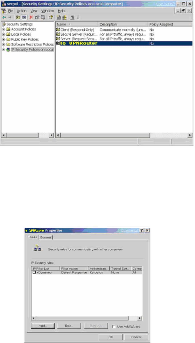
11g Wireless Security Router User Guide
- 68 -
4. Deselect the Activate the default response rule check box, and then click Next
button.
5. Click the Finish button, making sure the Edit check box is checked.
C-2.2 Build 2 Filter Lists: “WinXPÆBroadband VPN Router” and “Broadband VPN
RouterÆWinXP”.
[Filter List 1] WinXPÆ Broadband VPN Router
1. In the to_VPNRouter Properties, deselect the Use Add Wizard check box, and
then click Add button to create a new rule.
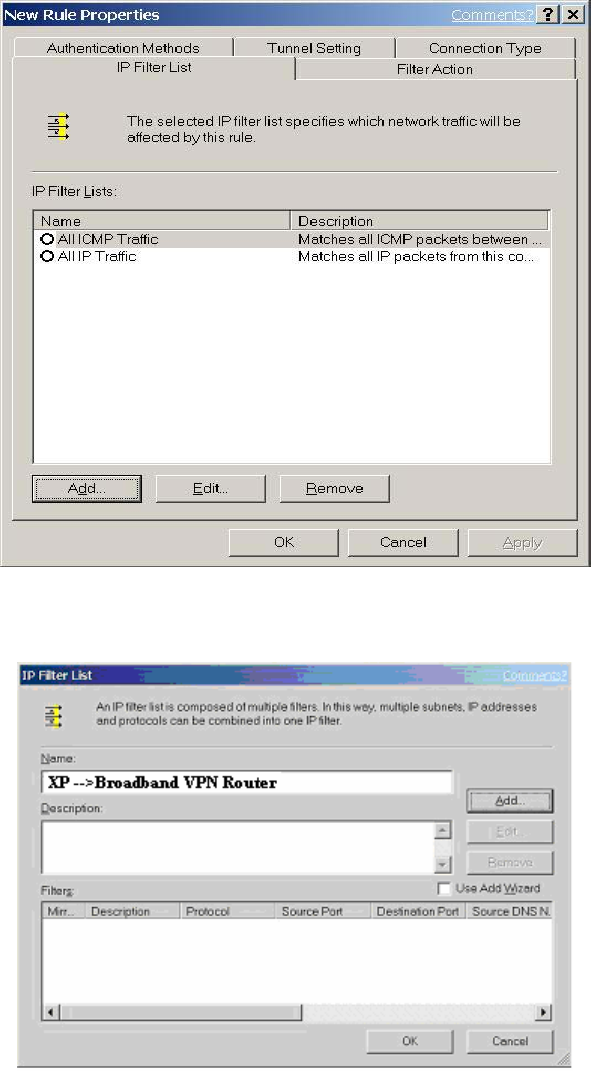
11g Wireless Security Router User Guide
- 69 -
2. From the IP Filter List tab, click the Add button.
3. Type an appropriate name “XPÆBroadband VPN Router” for the filter list,
deselect the Use Add Wizard check box, and then click Add button.
4. In the Source address area, click My IP Address.
5. In the Destination address field, select A specific IP Subnet, and fill in the IP
Address “192.168.1.0” and Subnet mask “255.255.255.0”.
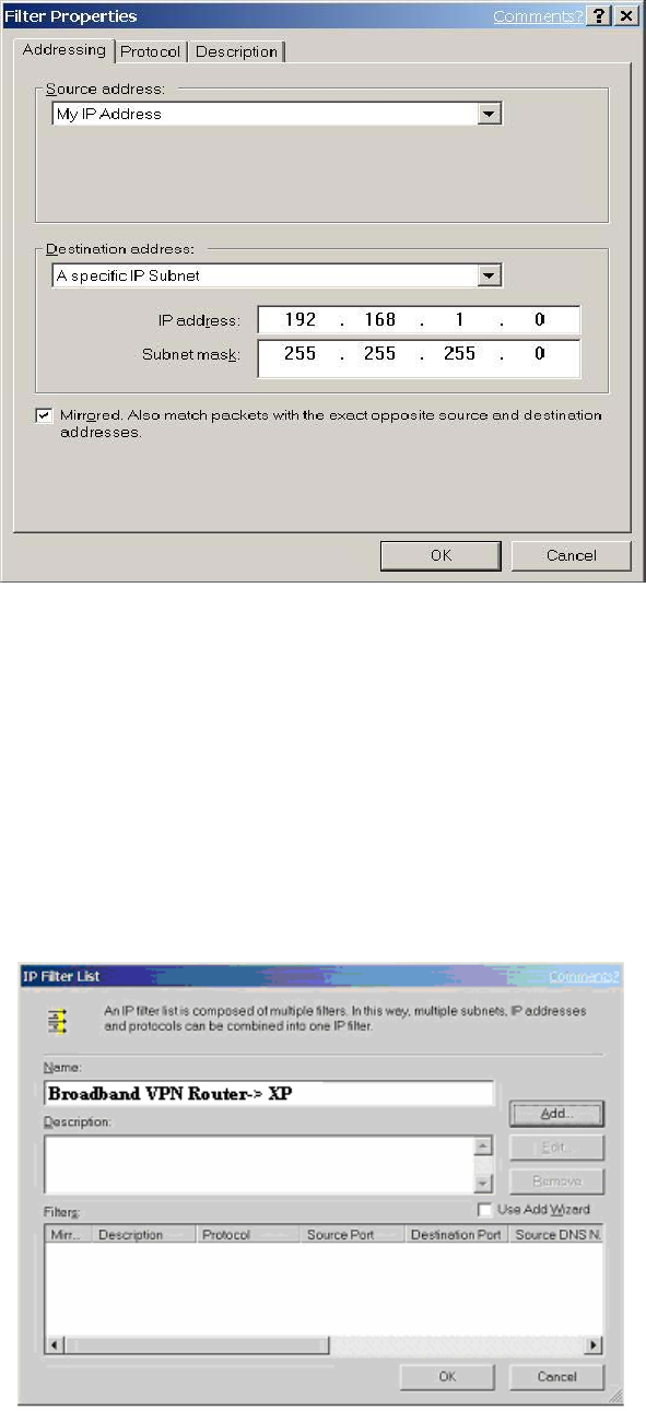
11g Wireless Security Router User Guide
- 70 -
6. If you want to type a description for your filter, click the Description tab.
7. Click OK button. Then click OK(for WinXP) or Close (for Win2000) button on
the IP Filter List Window.
[Filter List 2] Broadband VPN RouterÆWinXP
1. On the IP Filter List tab, click the Add button.
2. Type an appropriate name “Broadband VPN RouterÆXP” for the filter list,
click to clear the Use Add Wizard check box, and then click Add.
3. In the Source address area, click A specific IP Subnet, and fill in the IP
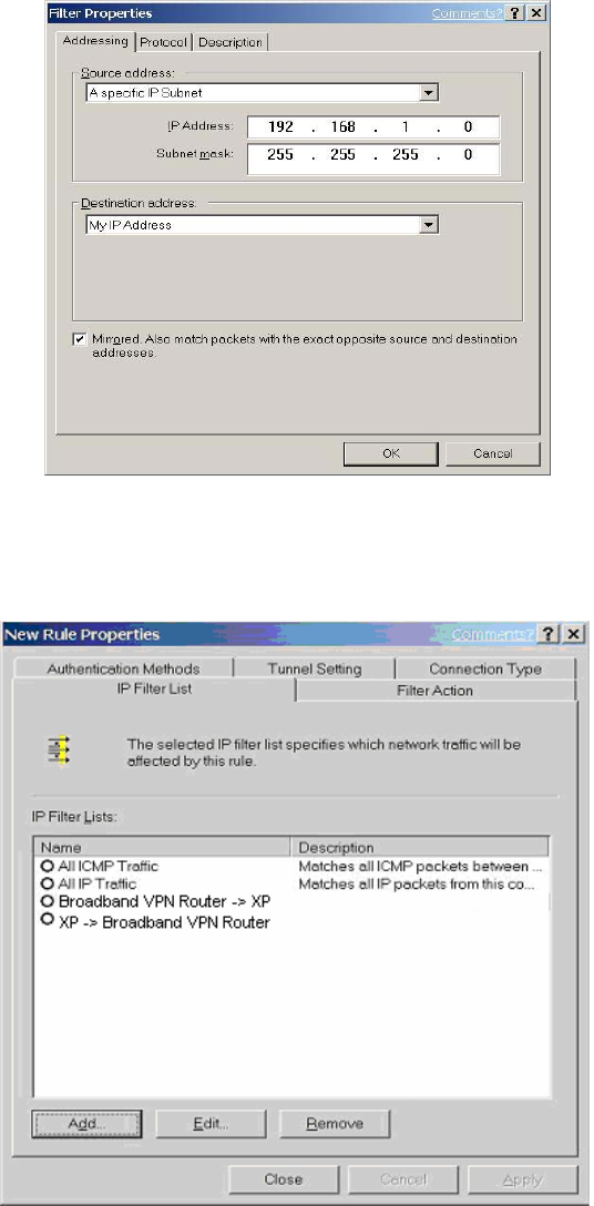
11g Wireless Security Router User Guide
- 71 -
Address “192.168.1.0” and Subnet mask “255.255.255.0”.
4. In the Destination address area, click My IP Address.
5. If you want to type a description for your filter, click the Description tab.
6. Click OK, and then click OK.
C-2.3 Configure Individual Rule of 2 Tunnels
[Tunnel 1] WinXPÆBroadband VPN Router
1. From the IP Filter List tab, click the filter list “XPÆBroadband VPN
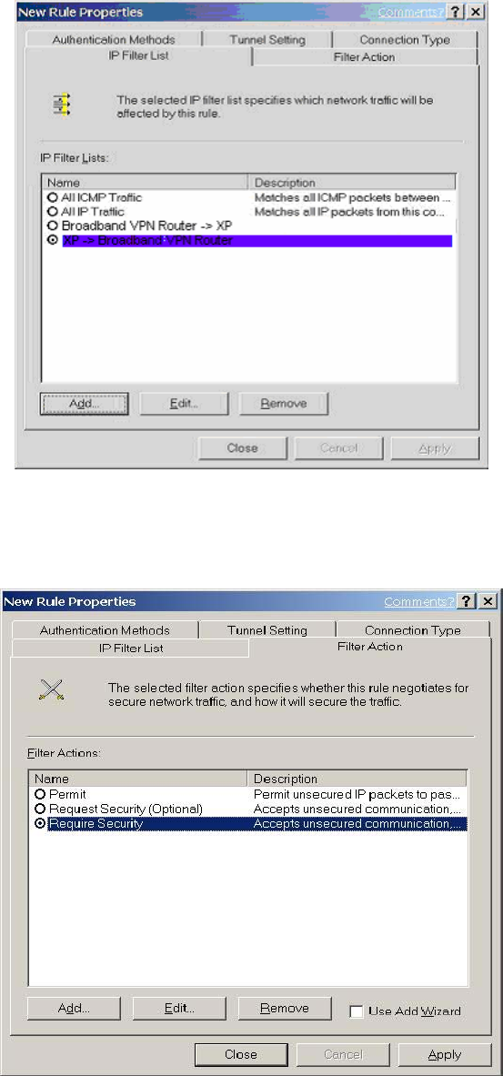
11g Wireless Security Router User Guide
- 72 -
Router”.
2. From the Filter Action tab, click the filter action “Require Security”, and click
the Edit button.
3. Check that the Negotiate security option is enabled, and deselect the Accept
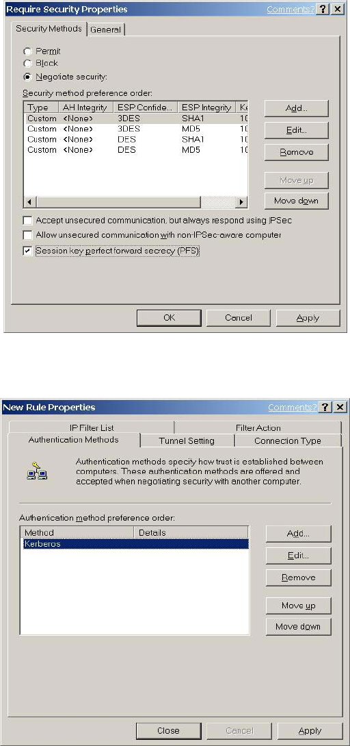
11g Wireless Security Router User Guide
- 73 -
unsecured communication, but always respond using IPsec check box.
4. Select the Session key Perfect Forward Secrecy (PFS) and remember to check
the PFS option on the Broadband VPN Router, and then click the OK button.
5. From the Authentication Methods tab, click the Edit button.
6. Change the authentication method to “Use this string (preshared key)”, enter
the string “Test”, and then click the OK button.
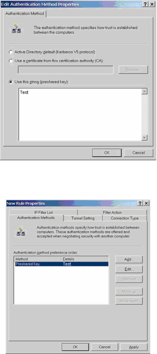
11g Wireless Security Router User Guide
- 74 -
This new Preshared key will be displayed in Authentication method preference
order. Click the OK button to continue.
7. From the Tunnel Setting tab, click The tunnel endpoint is specified by this IP
Address box, and then type the WAN IP Address “140.111.1.1”(Note: ISP
provided IP Address; this is only an example.)of the Broadband VPN Router.
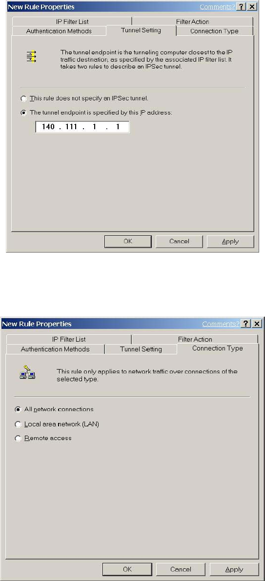
11g Wireless Security Router User Guide
- 75 -
8. From the Connection Type tab, select All network connections, and then click
the OK or Close button to finish this rule.
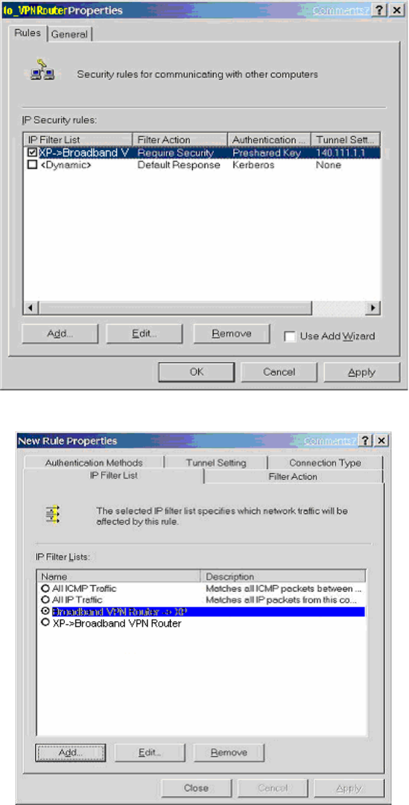
11g Wireless Security Router User Guide
- 76 -
[Tunnel 2] Broadband VPN RouterÆ WinXP
1. In the to_VPNRouter Properties, deselect the Use Add Wizard check box,
and then click the Add button to create the second IP Filter.
2. On the IP Filter List tab, click the filter list “Broadband VPN RouterÆXP”.
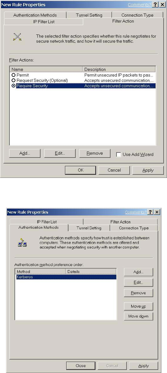
11g Wireless Security Router User Guide
- 77 -
3. From the Filter Action tab, click the filter action “Require Security”.
4. From the Authentication Methods tab, click the Edit button.
5. Change the authentication method to “Use this string (preshared key)”, enter
the string “Test”, and then click the OK button.
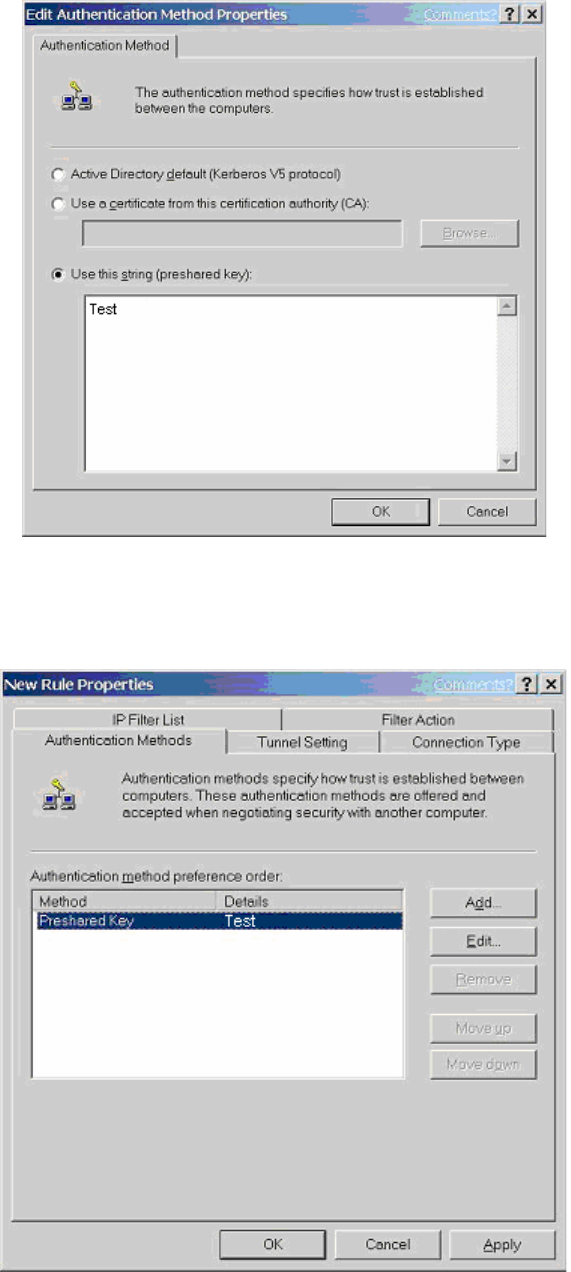
11g Wireless Security Router User Guide
- 78 -
This new Preshared key will be displayed in Authentication method preference
order. Click the OK button to continue.
6. From the Tunnel Setting tab, click The tunnel endpoint is specified by this IP
Address box, and then type the Windows 2000/XP IP Address “140.111.1.2”.
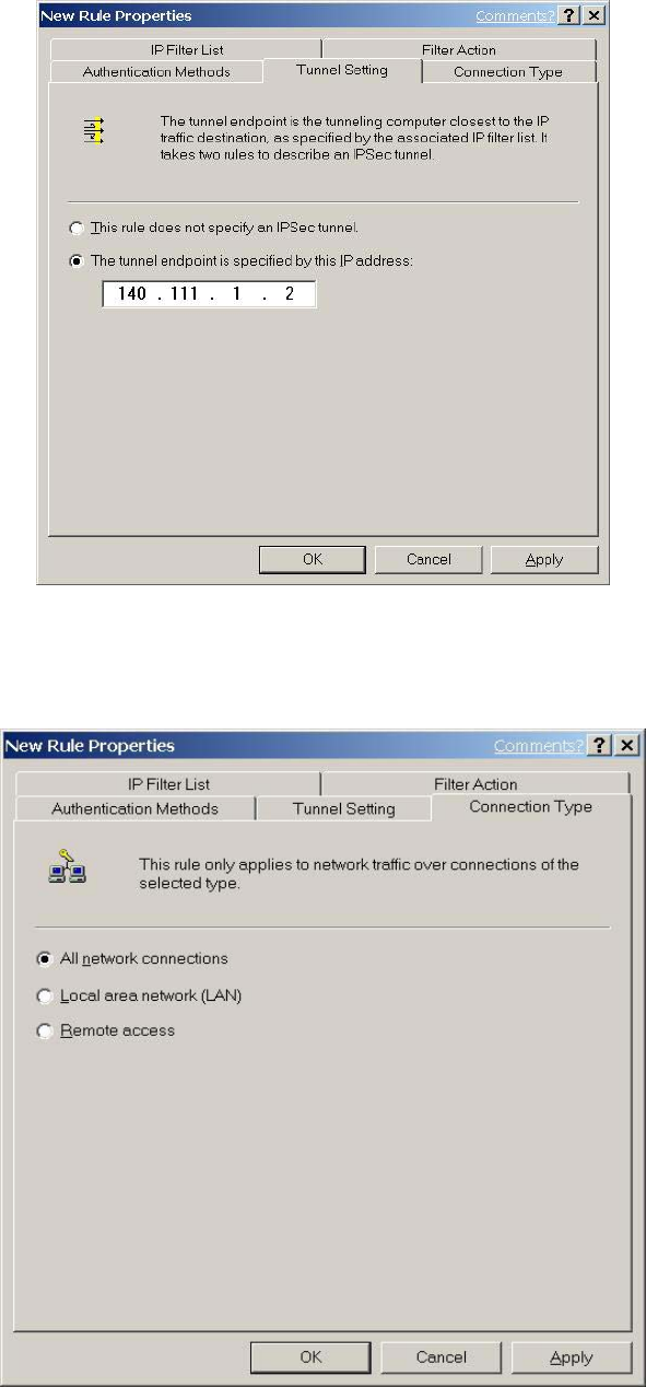
11g Wireless Security Router User Guide
- 79 -
7. From the Connection Type tab, select All network connections, and then click
the OK(for WinXP) or Close(for Win2000) button to finish.
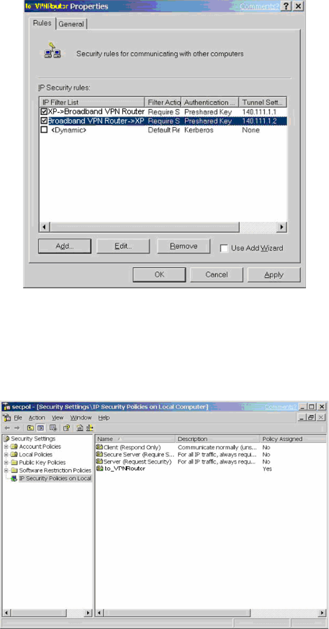
11g Wireless Security Router User Guide
- 80 -
8. From the Rules tab, click the OK button to back to the secpol screen.
C-2.4 Assign New IPsec Policy
1. In the IP Security Policies on Local Computer MMC snap-in, right-click policy
named “to_VPNRouter”, and then click Assign. A green arrow appears in the
folder icon.
11g Wireless Security Router User Guide
- 81 -
Appendix D: Glossary
10Base-T / 100Base-T
The adaptation of the Ethernet standard for Local Area Networks (LANs). 10Base-T uses
a twisted pair cable with maximum lengths of 100 meters and transmits data at 10Mbps
maximum. 100Base-T is similar, but uses two different twisted pair configurations and
transmits at 100Mbps maximun.
Ad-hoc Network
Also known as the peer-to-peer network, an ad-hoc network allows all PCs participating
in a wireless network and being within range, to communicate with each other. User’s in
the same ad-hoc network can share files, printers, and other network resources.
Adapter
A device that makes the connection to a network segment, such as Ethernet and modem
cards and adapters.
ADSL
Asymmetric Digital Subscriber Line (ADSL), as it’s name indicates, is an asymmetrical
data trasmission technology with higher traffic rate downstream and lower traffic rate
upstream. ADSL technology satisfies the bandwidth requirements of applications which
demand “asymmetric” traffic, such as web surfing, file downloads and telecommuting.
Bandwidth
The amount of data that can be transmitted in a fixed amount of time.
Browser
A software application used to locate and display Web pages. Examples include Netscape
Navigator and Microsoft Internet Explorer.
BSS
BSS is the acronym of Basic Service Set that consists of a wireless access point and a
group of wireless client PCs.
Communication Protocols
Communication between devices requires they agree on the format in which the data is to
be transmitted, sent and received. The communication protocols are a set of rules that
define the data format.
11g Wireless Security Router User Guide
- 82 -
Cookie
A Cookie is a piece of data stored on your PC that a web server can retrieve later to
identify your machine. It is normally a text with ID number, but can include other
information.
DHCP
DHCP, short for Dynamic Host Configuration Protocol, is a protocol for assigning
dynamic IP Addresses to devices on a network. Dynamic Addressing means that a device
can have a different IP Address each time it connects to the network.
Domain Name
A name that identifies one or more IP Addresses. For example, the domain name
microsoft.com represents about a dozen IP Addresses. Domain names are used in URLs
to identify particular Web pages. For example, in the URL
http://www.pcwebopedia.com/index.html, the domain name is pcwebopedia.com.
DoS
DoS is the abbreviation for Denial of Service. This occurs when a computer or network is
overwhelmed to the point that it can no longer function normally. For example, a hacker
may use fake IP addresses to accumulate numerious connections to flood the server he
wants to attack.
DDNS
DDNS is an acronym for Dynamic Domain Name Service. It helps map the domain name
of a host which has a dynamic public IP address to the IP address that is allocated each
time the ISP assigns a new IP address.
DNS
Short for Domain Name Server, DNS translates domain names into IP Addresses and
help us recognize and remember domain names as they are alphabetic in form. The
Internet actually runs on numbered IP Addresses. DNS servers translate domain names
into their respective IP Addresses.
DSSS
Also known as Direct Sequence Spread Spectrum, it is a radio transmission method that
continuously changes frequencies.
Ethernet
One of the most common Local Area Network (LAN) protocols. Ethernet uses a bus
topology which supports a data transfer rate of 10 Mbps.

11g Wireless Security Router User Guide
- 83 -
ESS
ESS is an acronym for Extend Service Set that consists of several BSS’s.
Firewall
A security system used to enforce an access control policy between an organisation’s
networks and the Internet.
IEEE
Short for Institute of Electrical and Electronics Engineers, an organization best known
for developing standards for the computer and electronics industry.
Internet
A global network connecting millions of computers for the exchange of data, news and
opinions.
Intranet
A network based on the TCP/IP Protocol (an internet) belonging to an organization, and
accessible only by that organization's members, employees, or others with authorization.
Infrastructure Network
Unlike “Aad-hoc” network, where users on a wireless LAN send data to each other
directly, users’ on an “Infrastructure” network send data to the other point through a
dedicated access point. Additionally, the access point enables users on a wireless LAN to
access an existing wired network to take advantage of sharing the wired networks
resources, such as files, printers, and Internet access.
IP Address
An identifier for a computer or device on a TCP/IP network. Networks using the TCP/IP
Protocol route messages based on the IP Address of the destination. The format of an IP
address is a 32-bit numeric address written as four numbers separated by periods. Each
number can be from zero to 255.
IPSec
Internet Protocol Security is a security standard for network transmission. It provides
authentication and packet encryption over the Internet.
ISP
Short for Internet Service Provider, a company that provides access to the Internet,
usually for a monthly fee. The ISP provides a software package, username, password and
access phone number allowing users to log on to the Internet, browse the World Wide
Web and send and receive e-mail.
11g Wireless Security Router User Guide
- 84 -
Local Area Network (LAN)
A computer network that spans a relatively small area. Most LANs are confined to a
single building or group of buildings. However, one LAN can be connected to other
LANs over any distance via telephone lines and radio waves. A system of LANs
connected in this way is called a wide area network (WAN)
MAC Address
Short for Media Access Control Address and in a hardware address that uniquely
identifies each node of a network.
NAT
Short for Network Address Translation, a routing protocol that allows global IP
Addresses to be translated into multiple private IP Addresses for use on internal LAN
networks. The explosion in the use of the Internet has created a critical problem for the
Internet Assigned Numbers Authority (IANA) which is in charge of assigning IP
Addresses to Internet users, ISPs etc.. NAT is a technology that has been introduced to
help maximize the utilization of assigned IAN and global IP Addresses.
Network Protocol
Network protocols encapsulate and forward data packets from one interface to another.
PAP/CHAP ISP
Short for Password Authentication Protocol and Challenge Handshake Authentication
Protocol. Most ISPs use either one for user identification. If your ISP doesn’t support
these two protocols, contact your ISP for an authentication script.
PPP
Short for Point-to-Point Protocol, a communications protocol for transmitting
information over standard telephone lines between devices from different manufacturers.
PPPoE
Short for PPP over Ethernet, relying on two widely accepted standards, Ethernet and the
Point-to-Point Protocol. It’s a communications protocol for transmitting information
between devices from different manufacturers over an Ethernet.
PPTP
Short for Point to Point Tunneling Protocol, PPTP encapsulates the packet for
transmission over the Internet. It is similar to creating a private “tunnel” over a large
public network and has almost equal security to a private network without actually
leasing a private line.

11g Wireless Security Router User Guide
- 85 -
Protocol
An agreed format for transmitting, sending and receiving data between two devices.
Roaming
The ability for a wireless device moving from one access point’s range to another without
losing the connection.
Router
An Internet device that routes requests for information to other routers until the
information’s location is found and the data can be transmitted back to the origin of the
request.
SPI
SPI is an acronym for Stateful Packet Inspection. The SPI engine examines not just the
headers of the packet, but also the packet contents, it can then determine more about the
packet than just its source and destination information. Moreover, stateful inspection
firewalls also close off ports until a connection to the specific port is requested.
TCP/IP
Short for Transmission Control Protocol and Internet Protocol, the suite of
communications protocols that enable hosts on the Internet to connect and exchange
streams of data.
VPN
VPN is an acronym for Virtual Private Network. Via access control and encryption, VPN
brings the same security to data transmission through the Internet as if it being
transmitted through a private network. It not only takes advantage of economies of scale
but also ensures high level security while the packet is sent over the large public network.
Wide Area Network (WAN)
A system of LANs being connected by telephone lines and radio waves. Although
someWANs may be privately owned, they are usually considered a means of public
access.
WEP
An acronym for Wired Equivalent Privacy. It is an encryption mechanism used to
protect your wireless data communications. WEP uses a combination of 64-bit/128-bit
keys to encrypt data that is transmitted between all points in a wireless network to insure
data security. It is described in the IEEE 802.11 standard.