CyberTAN Technology WM821M Wireless 802.11N DUAL BAND MINI PCI MODULE User Manual rev 0702
CyberTAN Technology Inc. Wireless 802.11N DUAL BAND MINI PCI MODULE rev 0702
User manual rev

WM821-M MiniPCI Module
WM821-M
Wireless 802.11N dual-band mini PCI module
User Manual
Rev 0.1

WM821-M MiniPCI Module
Federal Communication Commission Interference
Statement
This equipment has been tested and found to comply with the
limits for a Class B digital device, pursuant to Part 15 of the FCC
Rules. These limits are designed to provide reasonable protec-
tion against harmful interference in a residential installation. This
equipment generates, uses and can radiate radio frequency en-
ergy and, if not installed and used in accordance with the
instructions, may cause harmful interference to radio communi-
cations. However, there is no guarantee that interference will
not occur in a particular installation. If this equipment does
cause harmful interference to radio or television reception, which
can be determined by turning the equipment off and on, the user
is encouraged to try to correct the interference by one of the fol-
lowing measures:
- Reorient or relocate the receiving antenna.
- Increase the separation between the equipment and re-
ceiver.
- Connect the equipment into an outlet on a circuit different
from thatto which the receiver is connected.
- Consult the dealer or an experienced radio/TV technician
for help.
FCC Caution: Any changes or modifications not expressly ap-
proved by the party responsible for compliance could void the
user's authority to operate this equipment.
This device complies with Part 15 of the FCC Rules. Operation is
subject to the following two conditions: (1) This device may not
cause harmful interference, and (2) this device must accept any

WM821-M MiniPCI Module —
Introduction
ii
interference received, including interference that may cause un-
desired operation.
IMPORTANT NOTE:
FCC Radiation Exposure Statement:
This equipment complies with FCC radiation exposure limits set
forth for an uncontrolled environment. This equipment should be
installed and operated with minimum distance 20cm between the
radiator & your body.
This transmitter must not be co-located or operating in conjunc-
tion with any other antenna or transmitter.
Operations in the 5.15-5.25GHz band are restricted to indoor
usage only
IEEE 802.11b or 802.11g operation of this product in the U.S.A.
is firmware-limited to channels 1 through 11.
This device is intended only for OEM integrators under the
following conditions:
1) The antenna must be installed such that 20 cm is maintained
between the antenna and users, and
2) The transmitter module may not be co-located with any other
transmitter or antenna,
3) For all products market in US, OEM has to limit the operation
channels in CH1 to CH11 for 2.4G band by supplied firmware
programming tool. OEM shall not supply any tool or info to
the end-user regarding to Regulatory Domain change.
As long as 3 conditions above are met, further transmitter
test will not be required. However, the OEM integrator is still

Preface
iii
responsible for testing their end-product for any additional
compliance requirements required with this module installed
(for example, LVD TV… etc.).
IMPORTANT NOTE: In the event that these conditions can
not be met (for example certain laptop configurations or co-
location with another transmitter), then the FCC authoriza-
tion is no longer considered valid and the FCC ID can not be
used on the final product. In these circumstances, the OEM
integrator will be responsible for re-evaluating the end prod-
uct (including the transmitter) and obtaining a separate FCC
authorization.
End Product Labeling
This transmitter module is authorized only for use in device
where the antenna may be installed such that 20 cm may be
maintained between the antenna and users. The final end
product must be labeled in a visible area with the following:
“Contains FCC ID: N89-WM821M”.
Manual Information To the End User
The OEM integrator has to be aware not to provide
information to the end user regarding how to install
or remove this RF module in the user’s manual of
the end product which integrates this module.
The end user manual shall include all required regulatory in-
formation/warning as show in this manual.

WM821-M MiniPCI Module —
Introduction
iv
Canadian Regulatory Notice
This device complies with RSS-210 of the Industry Canada
Rules. Operation is subject to the following two conditions:
1) this device may not cause interference and
2) this device must accept any interference, including interfer-
ence that may cause undesired operation of the device
Caution:
The device for the band 5150-5250 MHz is only for indoor usage
to reduce potential for harmful interference to co-channel mobile
satellite systems.
IMPORTANT NOTE:
IC Radiation Exposure Statement:
This equipment complies with IC radiation exposure limits set
forth for an uncontrolled environment. This equipment should be
installed and operated with minimum distance 20cm between the
radiator and your body.
Industry Canada Interference Statement
The device for the band 5150-5250 MHz is only for indoor usage
to reduce potential for harmful interference to co-channel mobile
satellite systems;
The maximum antenna gain permitted (for devices in the bands
5250-5350 MHz and 5470-5725 MHz) to comply with the e.i.r.p.
limit; and
The maximum antenna gain permitted (for devices in the band
5725-5825 MHz) to comply with the e.i.r.p. limits specified for

Preface
v
point-to-point and non point-to-point operation as appropriate, as
stated in section A9.2(3).
In addition, users should also be cautioned to take note that
high-power radars are allocated as primary users (meaning they
have priority) of the bands 5250-5350 MHz and 5650-5850 MHz
and these radars could cause interference and/or damage to LE-
LAN devices.
Note: The WM821-M has disable the 5600-5650M band by
S/W to avoid 5600-5650M band for IC certification

WM821-M MiniPCI Module —
Introduction
vi
Table of contents
Introduction 1
Hardware installation 5
Using the Wireless Utility 7

WM821-M MiniPCI Module
1
Chapter 1
Introduction
Thank you for using the Wireless MiniPCI Module. The WM821-
M is a dual-band, quad-mode wireless network adapter that
works on all the frequencies allocated for WLAN operation eve-
rywhere in the world. It is in compliance with the Draft
IEEE802.11n standard in a 2x3 MIMO configuration. It also
complies with the IEEE 802.11a, 802.11g, and 802.11b stan-
dards. WM821-M features the compactness and high bus
speed of the Mini PCI specifications which gives users of lap-
tops, notebooks, tablet PCs, and other mobile computing
devices transparent Internet access anywhere in the world
through any Wi Fi network without software changes or addi-
tional hardware.
Able to provide greater than 100Mbps real world throughput
using high-speed spatial multiplexing modes, the WM821-M
provides the freedom to work as you wish, wherever you wish,
using whatever kind of application you wish to use. The adapter
installs directly in any host device with a Mini PCI slot: just plug
it in and you’re ready to access local resources and/or the Inter-
net at the highest speed the WLAN, the location, and the host
computer can provide. It is ready to work “out of the box” in any
embedded device or in any computer running Microsoft® Win-
dows 2000, or XP (TBD). The WM821-M Mini PCI Card is truly
a “must-have” for every productivity-sensitive laptop, notebook,

WM821-M MiniPCI Module —Introduction
2
or tablet PC user and any bandwidth-sensitive embedded de-
sign..
Features
• mPCI 32 interface.
• Draft IEEE 802.11n compatible.
• Backward compatible with IEEE 802.11a/b/g standard.
• Wire-free access to networked resources from anywhere
beyond the desktop.
• Delivers data rates up to 300 Mbps.
• 802.11n: Dynamically shifts among 130, 117, 104, 78, 52,
39, 26 and 13Mbps in a 20MHz bandwidth and 300, 243,
216, 162, 108, 81, 54 and 27Mbps in a 40MHz bandwidth,
based on signal strength, for maximum availability and reli-
ability of connection.
• 802.11a/g: Dynamically shifts between 54, 48, 36, 24, 18,
12, 9 and 6 Mbps network speed, based on signal strength,
for maximum availability and reliability of connection.
• 802.11b: Dynamically shifts between 11M, 5.5M, 2M, and 1
Mbps network speed, based on signal strength, for maxi-
mum availability and reliability of connection.
• Supports 802.11h (DFS) power adjustment.
• Allows users move between Access Points without reset-
ting the connection reconfigurations.
• Three ultra-mini connectors with for diversity antennae.
• Uses 2.4GHz and 5GHz frequency band, complying with
regulatories worldwide
• Supports most popular operating systems: Window
2000/XP. Linux support is also available.
• Ensures great security by providing the 64/128 bits Wired
Equivalent Privacy (WEP) and WiFi Protected Access
(WPA) defined in the IEEE standard.
• WPA support with Funk client. Radius clients in EAP-TLS,
EAP, TTLS, EAP-LEAP, EAP, PEAP.
• WPA2, WMM-compliant.

—Introduction
3
WiFi-Protected Setup(WPS)-supportedWhat
is Wireless LAN?
Wireless Local Area Network (WLAN) systems offer a great
number of advantages over traditional wired systems. WLANs
are flexible and easy to setup and manage. They are also more
economical than wired LAN systems.
Using radio frequency (RF) technology, WLANs transmit and
receive data through the air. WLANs combine data connectivity
with user mobility. For example, users can roam from a confer-
ence room to their office without being disconnected from the
LAN.
Using WLANs, users can conveniently access shared informa-
tion, and network administrators can configure and augment
networks without installing or moving network cables.
WLAN technology provides users with many convenient and
cost saving features:
• Mobility: WLANs provide LAN users with access to real-
time information anywhere in their organization, providing
service opportunities that are impossible with wired net-
works.
• Ease of Installation: Installing is easy for novice and ex-
pert users alike, eliminating the need to install network
cables in walls and ceilings.
• Scalability: WLANs can be configured in a variety of to-
pologies to adapt to specific applications and installations.
Configurations are easily changed and range from peer-
to-peer networks suitable for a small number of users to

WM821-M MiniPCI Module —Introduction
4
full infrastructure networks of thousands of users roaming
over a broad area.

5
Chapter 2
Hardware installation
This chapter covers how to installing the Wireless MiniPCI
Module in your embedded system.
Hardware description
The Wireless MiniPCI Module has a standard MiniPCI inter-
face for attaching to the MiniPCI connector on embedded
system.
And this module has IPEX connector to connect to external
antenna.
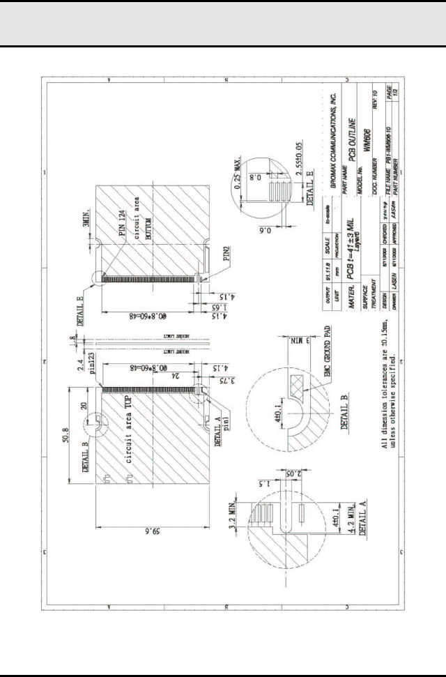
Outlook
Following is the MiniPCI module outlook
WM821-M MiniPCI Module —
Hardware installation
6
Figure 1: MiniPCI module outlook

7
Chapter 3
Using the Wireless Utility
This module also come with a wireless utility, following describe
how to use the utility.
Configuration Utility
The Client Card Configuration Utility allows configuration of WM821-M high
throughput client cards through the following tabs:
•
Network Status—displays the status of the network to which the
user is connected. The Configuration Utility
initializes on this page.
•
Profile Manager—displays the current profiles and allows the user to set
attributes for network type, security options, and
protocols, as well as create/modify/delete profiles.
•
Site Survey—displays site survey information.
•
Statistics—displays the statistics of the current session.
•
Advanced—used to set protocol parameters.
•
AutoLink—to set AutoLink connection
•
Admin—used to import and export profiles.
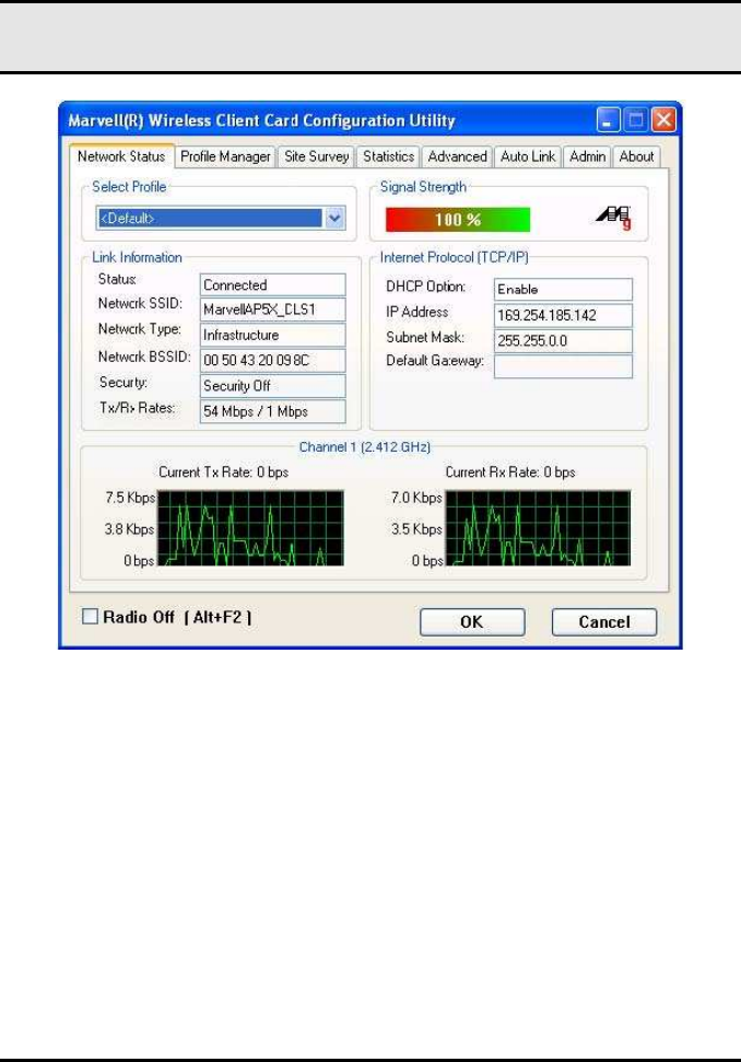
3.1 Network Status Tab
The Network Status tab displays the status of the network. When the Wireless
client card Configuration Utility initializes, it displays the Network Status tab.
WM821-M MiniPCI Module —Using the
Wireless Utility
8
Figure 2 :Network Status tab
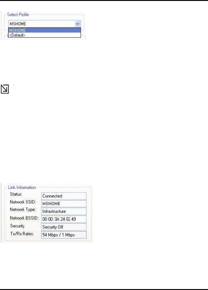
3.1.1 Select Profile
The Select Profile section displays the name of the profile in use. Additional infor-
mation about the profile is provided in the Profile Manager.
Select one of the profiles previously defined by clicking the down arrow and high-
lighting a profile from the pull-down list.
Figure 3: Select Profile Section
Appendix B Error Messages of Enabler Program
9
Figure 3: Select Profile
Profiles are created, modified, and deleted through the ProfileMan-
ager.
Note
This feature is disabled when Windows Zero Configuration Utility is enabled.
3.1.2 Link Information
The Link Information section contains the current information about the wireless
connection.
Figure 4: Link Information Section
Figure 4: Link Information Section

WM821-M MiniPCI Module —Using the
Wireless Utility
10
Table 1:Link Information
Field Description
Status Status of the wireless network connection:
•
Card Unplugged Client card is not plugged in, or client card
is plugged in but not recognized.
•
Connected
Client card is plugged in and connected to a wireless network.
•
No Connection
Client card is plugged in, but no wireless connection.
•
No Radio
Client card is plugged in, but the radio is turned off. Clear the
Radio Off check box to turn the radio on.
•
Scanning for Scanning for available APs and wireless sta-
tions in the area.
Network SSID Network SSID label (i.e., Network Name). The Network Name
is a text string of up to
32 characters.
Network Type Type of environment connected to:
•
Infrastructure Mode In
this mode, wireless clients send and receive information
through APs. When a wireless client communicates with an-
other, it transmits to the AP. First the AP receives the
information and rebroadcasts it, then other devices receive the
information. The APs are strategically located within an area to
provide optimal coverage for wireless clients. A large WLAN
uses multiple APs to provide coverage over a wide area. APs
can connect to a LAN through a wired Ethernet connection.
APs send and receive information from the LAN through the
wired connection.
Appendix B Error Messages of Enabler Program
11
Network BSSID
Network Basic Service Set Identifier. The BSSID is a 48-bit
identity used to identify a particular BSS within an area. In In-
frastructure BSS networks, the BSSID is the MAC
Security Reports the type and level of security set. The security level is
set through the Profile
Setting of the Profile Manager tab. Configure security settings
also through the Site
Survey tab when connecting to a network.
Tx/Rx Rates Current Tx Rate and Rx Rate of the channel being monitored.
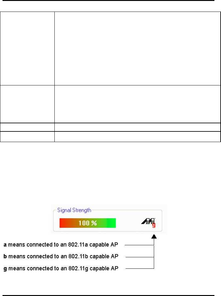
3.1.3 Signal Strength / Wireless Mode Indicator
The color-coded Signal Strength bar displays the signal strength of the last packet
received by the client card.
Figure 5: Signal Strength
WM821-M MiniPCI Module —Using the
Wireless Utility
12
Signal strength is reported as a percentage. A signal in the red indicates a bad con-
nection. A signal in the green indicates a good connection.
The Wireless Mode indicator shows the data rates the client card operates. There
are three modes:
.
•
802.11a
.
•
802.11b
.
•
802.11g (backward compatible to 802.11b)
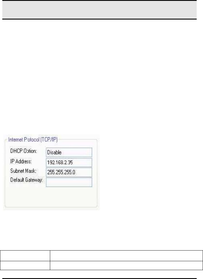
3.1.4 Internet Protocol (TCP/IP)
The Internet Protocol specifies the format of packets, also called data grams, and
the addressing scheme. Most networks combine IP with a higher-level protocol
called TCP, which establishes a virtual connection between a destination and a
source.
Figure 6:Internet Potocol Section
Table 2 Internet Protocol Section Description
Field Description
DHCP Option Dynamic Host Configuration Protocol. Either enabled or dis-
Appendix B Error Messages of Enabler Program
13
abled.
IP Address An identifier for a computer or device on a TCP/IP network. The
format of an IP address
is a 32-bit numeric address written as four numbers separated
by periods. Each number
can be 0 to 255.
Subnet Mask A mask used to determine what subnet an IP address belongs
to. An IP address has two
components, the network address and the host address. The
first two numbers represent the Class B network address, and
the second two numbers identify a particular host on
this network.
Default Gateway The default node on a network that serves as an entrance to
another network. In enterprises, the gateway is the computer
that routes the traffic from a workstation to the outside network
that is serving the Web pages. In homes, the gateway is the
ISP that connects the user to the Internet.
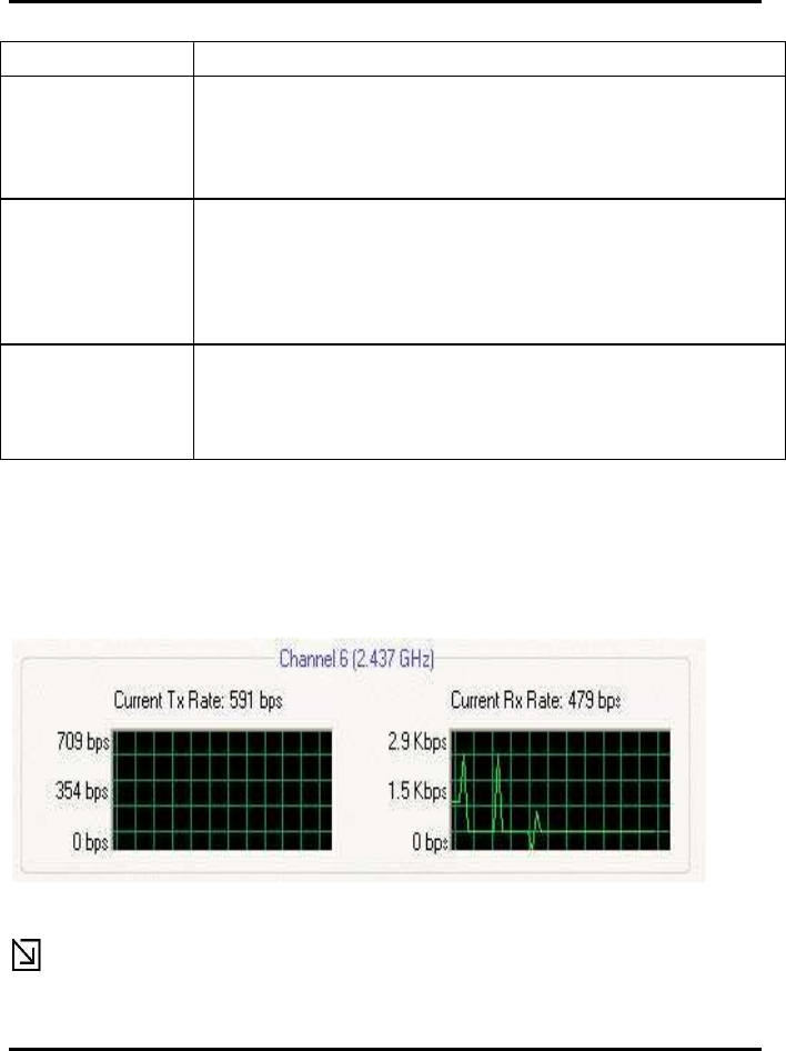
3.1.5 Actual Throughput Performance
This section of the Network Status tab displays the Current Tx Rate and the Cur-
rent Rx Rate of the channel being monitored.
Figure 7: actual throughput diagrams
Note
WM821-M MiniPCI Module —Using the
Wireless Utility
14
These are actual throughput diagrams (without the WLAN overhead delivered by
the client card).
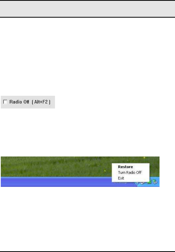
3.1.6 Radio On/Off Check Box
Selecting the Radio Off check box turns off the radio. Clearing the check
box turns on the radio.
Figure 8: Radio On/Off Check Box
Figure 8:Radio On/Off Check Box
Another way to turn the radio on or off is to right-click the Configuration Utility icon
in System Tray and select Turn Radio Off to turn the radio off. When the radio is
off, select Turn Radio On to turn the radio back on.
Figure 9: Radio On/Off in the System Tray
The system hot key Alt+F2 can also be used to turn the radio on/off.
When the radio is off, there is no radio activity, and the following tabs are disabled:
.
•
Profile Manager
.
•
Site Survey
.
•
Statistics

Appendix B Error Messages of Enabler Program
15
.
•
Advanced
.
•
AutoLink
Note
This feature is disabled when Windows Zero Configuration Utility is enabled.
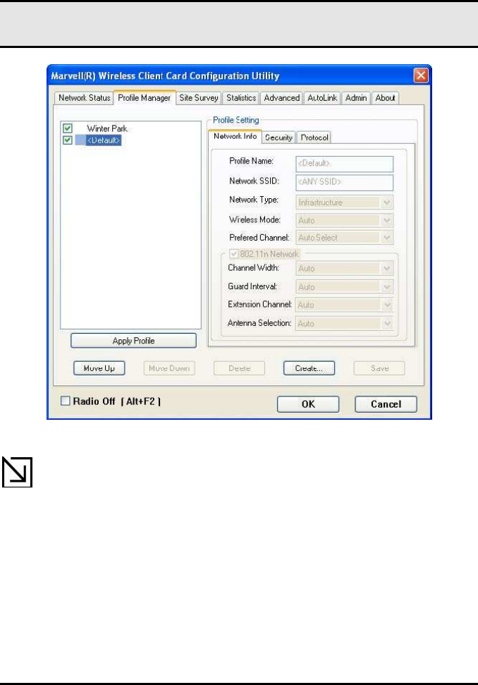
3.2 Profile Manager Tab
The Profile Manager tab displays the profiles available and allows you to create,
modify, and delete profiles.
WM821-M MiniPCI Module —Using the
Wireless Utility
16
Figure 10:
Figure 14: Profile Manager Tab
Note
The Profile Manager tab is not accessible when Windows Zero
Configuration Utility is enabled.

Appendix B Error Messages of Enabler Program
17
PROFILE MANAGER—PROFILE LIST
The section on the left side of this tab lists all of the profiles available. Highlighting a
profile selects it. If the check box next to the profile is selected, that profile is used
in auto-configuration mode when the link is lost. If it is not selected, that profile is
excluded in auto-configuration. The buttons associated with this window are as fol-
lows.
Table 3: Profile List Section Description
Button Description
Apply Profile Applies the profile selected.
Apply the profile by double-clicking the desired profile.
Move Up / Down Moves the list up and down in the window.
Delete Deletes a profile
Create Creates a profile
Save Saves changes made to a selected profile
PROFILE MANAGER—PROFILE SETTING
The Profile Settings are used to
set, modify, and display information about the profile selected in the Profile List
section. The information is divided into three tabs:
.
•
Network Info
.
•
Security
.
•
Protocol
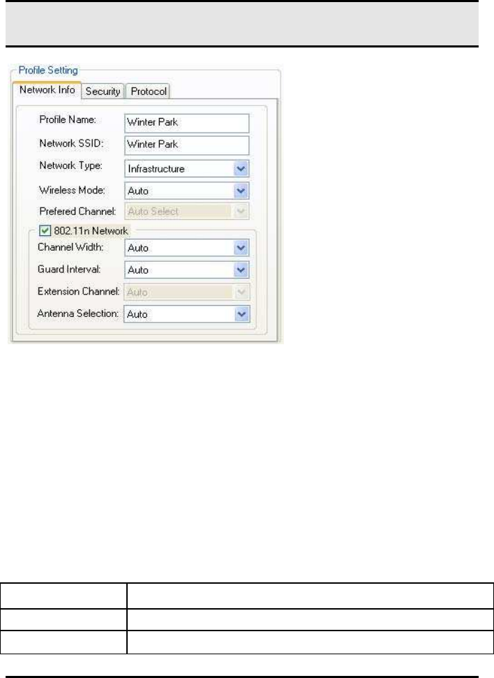
3.2.1 Profile Setting—Network Info Tab
The Profile Manager initially displays the Network Info tab.
WM821-M MiniPCI Module —Using the
Wireless Utility
18
Figure 11:
Network Info Tab (Infrastructure Network)
The Network Info tab fields are as follows.
Table 4:
::
: Network Info Tab Description
Field Description
Profile Name Name of profile selected
Network SSID Network SSID label

Appendix B Error Messages of Enabler Program
19
Network Type
•
Infrastructure When an Infrastructure network is selected,
the Profile Setting displays the Wireless Mode field.
Wireless Mode
•
Auto
Connects to 802.11a network, 802.11g network, or 802.11b
network (Infrastructure network only).
•
802.11a
Connects to 802.11a only.
•
802.11g Connects to either 802.11g network or 802.11b
network.
•
802.11b
Connects to 802.11b network only.
802.11n Network Enables/disables draft-802.11n/EWC functionality.
If enabled, the Modulation and Coding Scheme (MCS) index
and 802.11n options can
be configured.
Channel Width Sets the channel bandwidth. Available options are Auto, 20
MHz, and 40 MHz.
The default is Auto.
Guard Interval Sets the Guard Interval. Available options are Auto, Standard,
and Short.
The default is Auto.
Extension Channel
Sets the extension channel mode when bandwidth is 40 MHz.
Available options are
Auto, None, Lower, and Upper. The default is Auto.
Antenna Selection
Sets the antenna selections. Available options are Auto, An-
tenna A, Antenna B, 2 by 2,
and 2 by 3. The default is Auto.
WM821-M MiniPCI Module —Using the
Wireless Utility
20
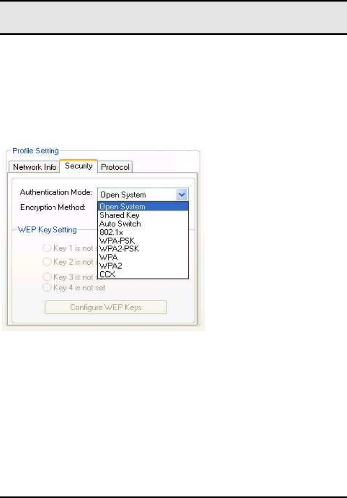
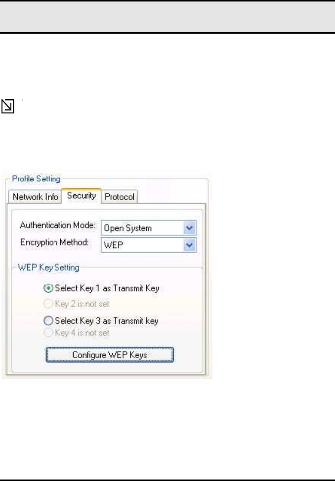
3.2.2 Profile Setting—Security Tab
Clicking the Security tab displays
the following security options:
.
•
Authentication Mode
.
•
Encryption Mode (Security off, WEP, TKIP, and AES)
.
•
WEP Key Setting (Passphrase Key or Authentication Protocol)
Figure 12:
::
: Security tab
3.2.2.1 Non-EAP Authentication Modes
The WM821-M Configuration Utility currently supports the following non-EAP au-
thentication modes:
.
•
Open System
—
Open Authentication (no key or a pre-shared WEP key is
. required).
.
•
Shared Key
—
Shared Authentication (a pre-shared WEP key is required)
.
•
Auto Switch
—
Auto Select Authentication modes (Open System or Shared
. Key, WEP key required)
Appendix B Error Messages of Enabler Program
21
.
•
WPA-PSK—WPA Pre-Shared Key
.
•
WPA2-PSK—WPA2 Pre-Shared Key
3.2.2.2 EAP Authentication Modes
The WM821-M Configuration Utility currently supports the following EAP authentica-
tion modes:
.
•
802.1x (TLS/PEAP)
.
•
WPA (TLS/PEAP/LEAP)
.
•
WPA2 (TLS/PEAP/LEAP)
.
•
CCX (LEAP)
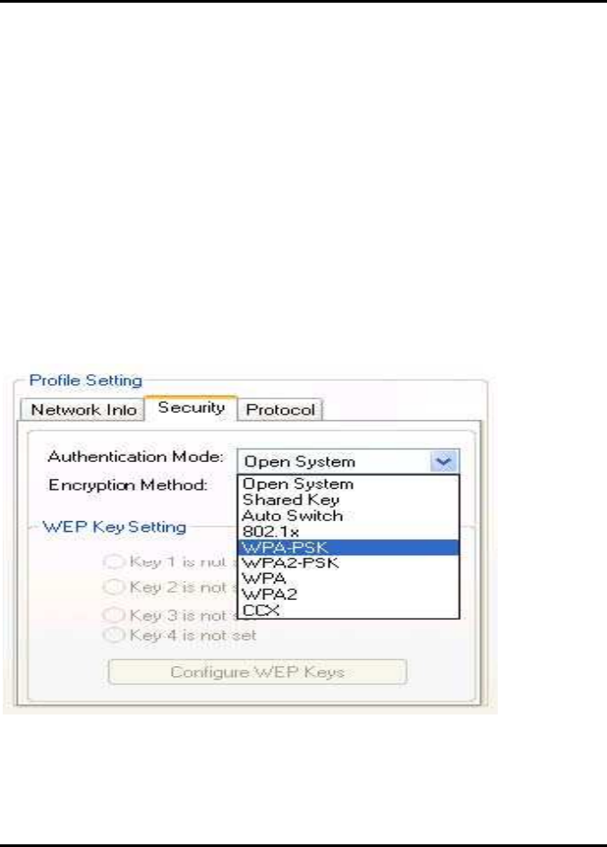
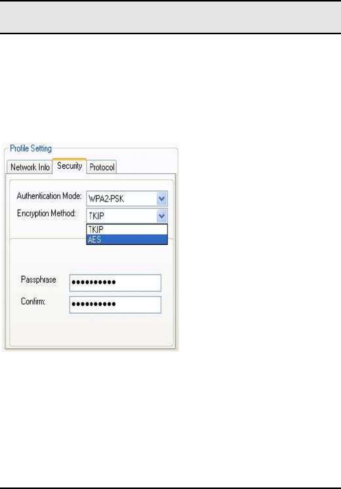
3.2.2.2.1 WPA-PSK/WPA2-PSK SUPPORT
In Infrastructure mode, if WPA-PSK/WPA2-PSK is selected as the Authentication
Mode, the encryption method AES or TKIP can be selected.
Figure 13:
Security selection
WM821-M MiniPCI Module —Using the
Wireless Utility
22
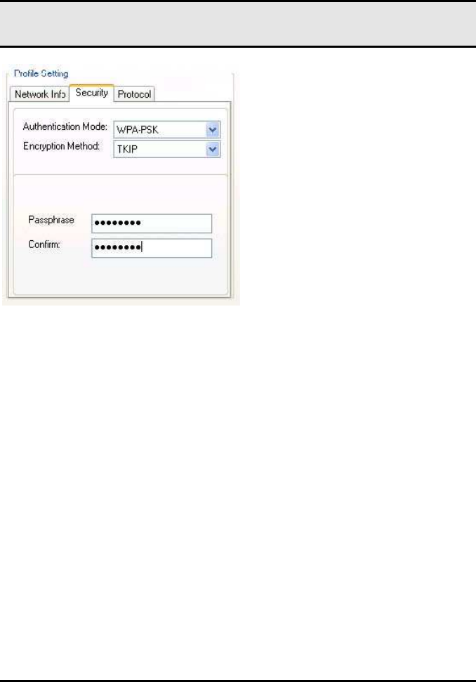
Figure 14:
Security Tab—WPA-PSK/WPA2-PSK with TKIP
Enter the network passphrase into the Passphrase and Confirm boxes.
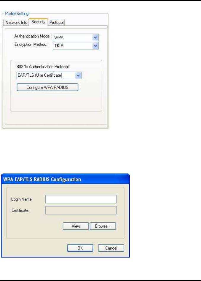
3.2.2.2.2 802.1X/WPA/WPA2 EAP/TLS SUPPORT
If the 802.1x EAP/TLS option is selected, the encryption method AES or TKIP can
be selected, and a certificate is required for the authentication.
1. 1. To connect to an AP through the RADIUS server, select 802.1x
WPA/WPA2 as the Authentication Mode.
2. 2. Select TKIP or AES as the Encryption Method.
3. 3. Select EAP/TLS (Use Certificate) as the 802.1x Authentication Protocol.
Appendix B Error Messages of Enabler Program
23
Figure 15:
::
:
Security Tab—802.1x/WPA/WPA2 EAP/TLS Authentication
4. Click the Configure WPA RADIUS button to configure security settings.
Figure 16:
::
:
802.1x/WPA/WPA2 EAP/TLS RADIUS Configuration Window
WM821-M MiniPCI Module —Using the
Wireless Utility
24
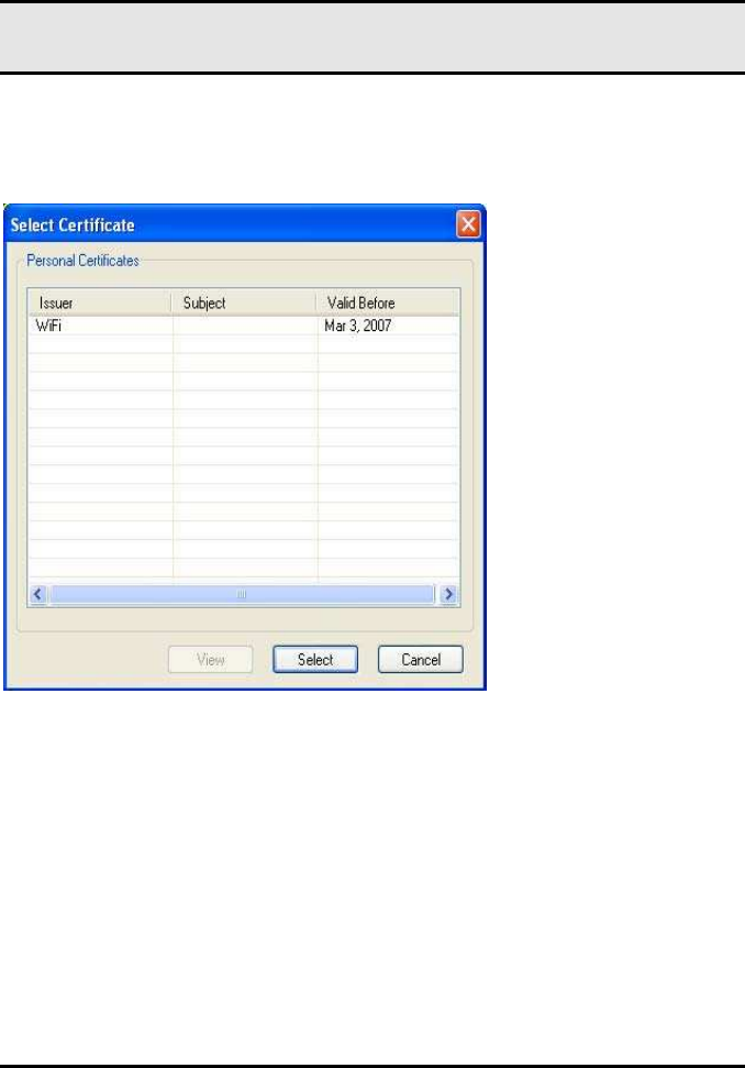
1. 5. Click Browse to activate the dialog for selecting a certificate.
2. 6. Before clicking OK to exit the dialog, make sure that the Login Name is
entered.
Figure 17:
::
:
Select Certificate
Appendix B Error Messages of Enabler Program
25
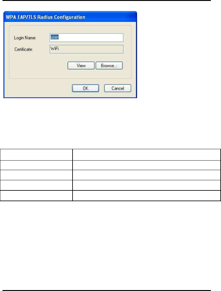
Figure 18:
WPA RADIUS Configuration Window with Certificate
Table 5:
::
: 802.1x/WPA/WPA2 EAP/TLS RADIUS Configuration Window Descrip-
tion
Field/Button Description
Login Name Login name to the RADIUS server
Certificate Certificate selected for authentication
View Shows the selected certificate
Browse Selects the certificate
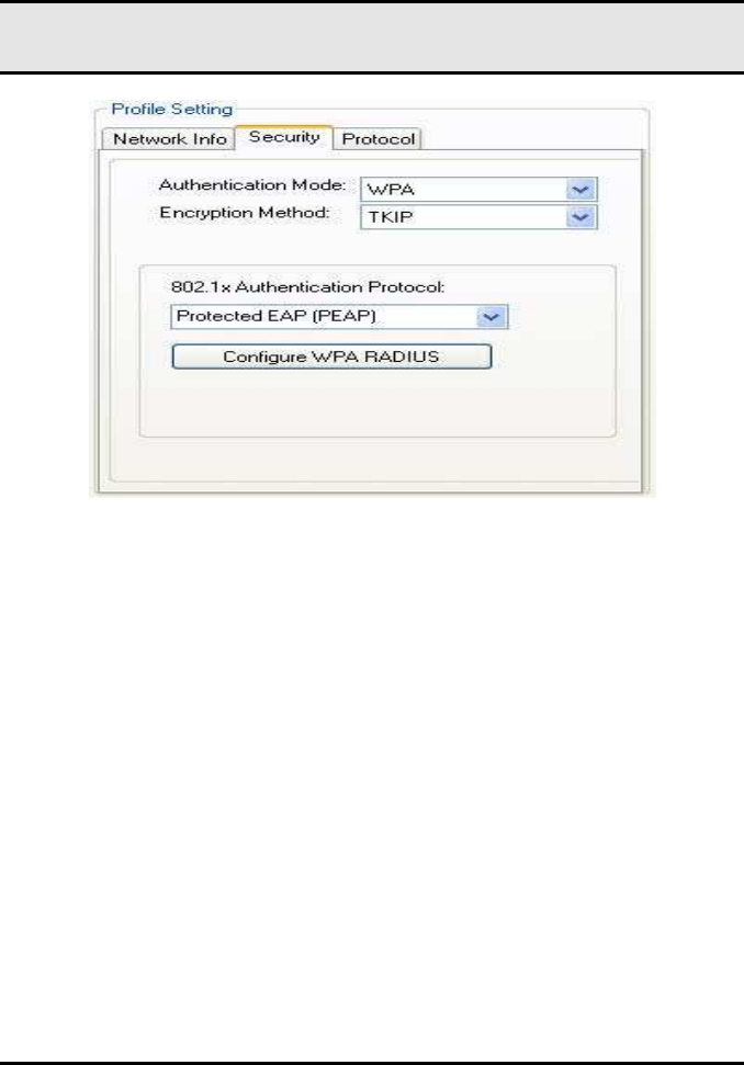
3.2.2.2.3 802.1X/WPA/WPA2 PEAP SUPPORT IN INFRASTRUCTURE
MODE
To connect to an AP through the RADIUS server, select 802.1x/WPA/WPA2 as the
Authentication Mode, PEAP as the Authentication Protocol, and AES or TKIP as the
Encryption Method.
WM821-M MiniPCI Module —Using the
Wireless Utility
26
Figure 19:
::
:Security tab
802.1x/WPA/WPA2 PEAP RADIUS
Authentication
Figure 25: 802.1x/WPA/WPA2 PEAP RADIUS
Configuration Window
Appendix B Error Messages of Enabler Program
27
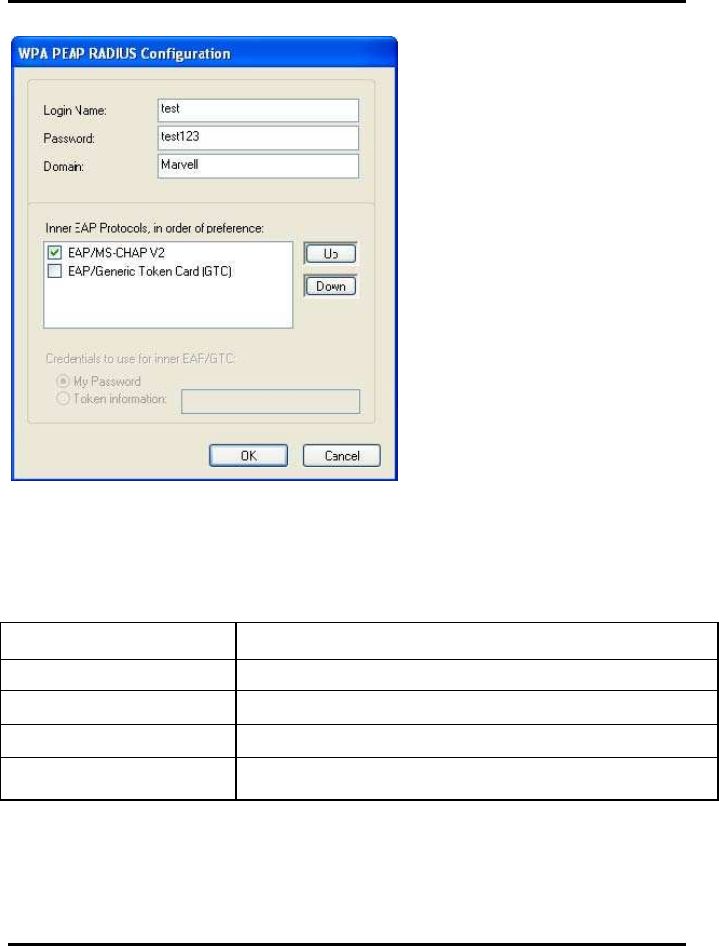
Figure 20:
802.1x/WPA/WPA2 PEAP RADIUS Configuration Window
Table 6: WPA PEAP RADIUS Configuration Window Description
Field Description
Login Name Login name to the RADIUS server
Password Password to login to the RADIUS server
Domain Domain name for login to the RADIUS server (optional)
Inner EAP Protocol Use EAP/MS-CHAP V2 or EAP/GTC to login to the
RADIUS server
Click OK to set the configuration.
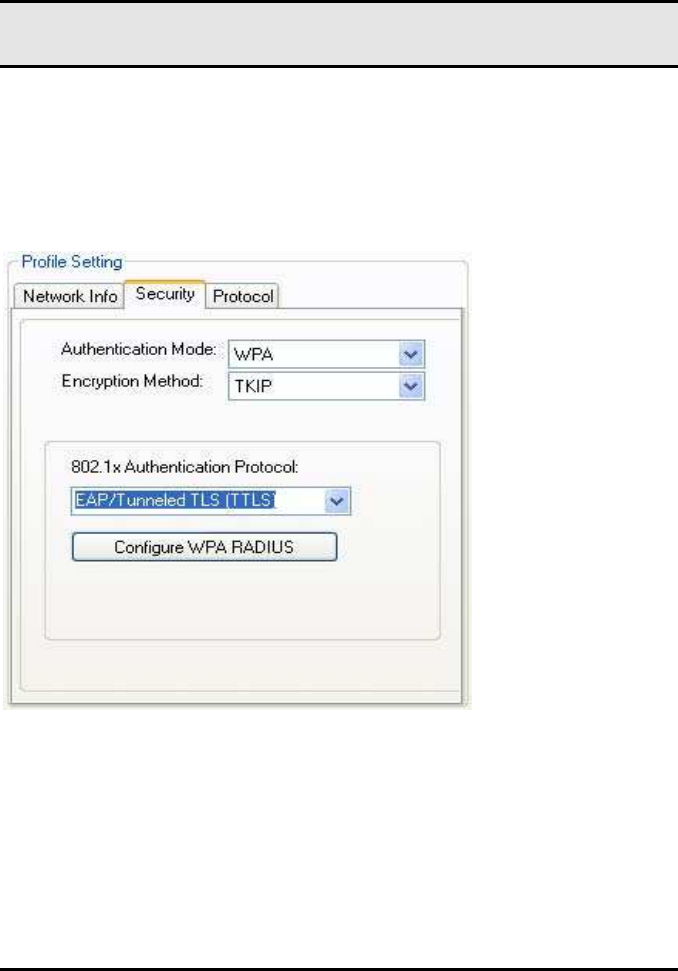
3.2.2.2.4 WPA/WPA2 EAP/TTLS
WM821-M MiniPCI Module —Using the
Wireless Utility
28
To connect to an AP through the RADIUS server, select WPA/WPA2 as the Au-
thentication Mode, TTLS as the 802.1x Authentication Protocol, and TKIP as the
Encryption Method for WPA TTLS or AES as the Encryption Method for WPA2
TTLS.
Figure 21:
WPA/WPA2 EAP/TTLS
Authentication
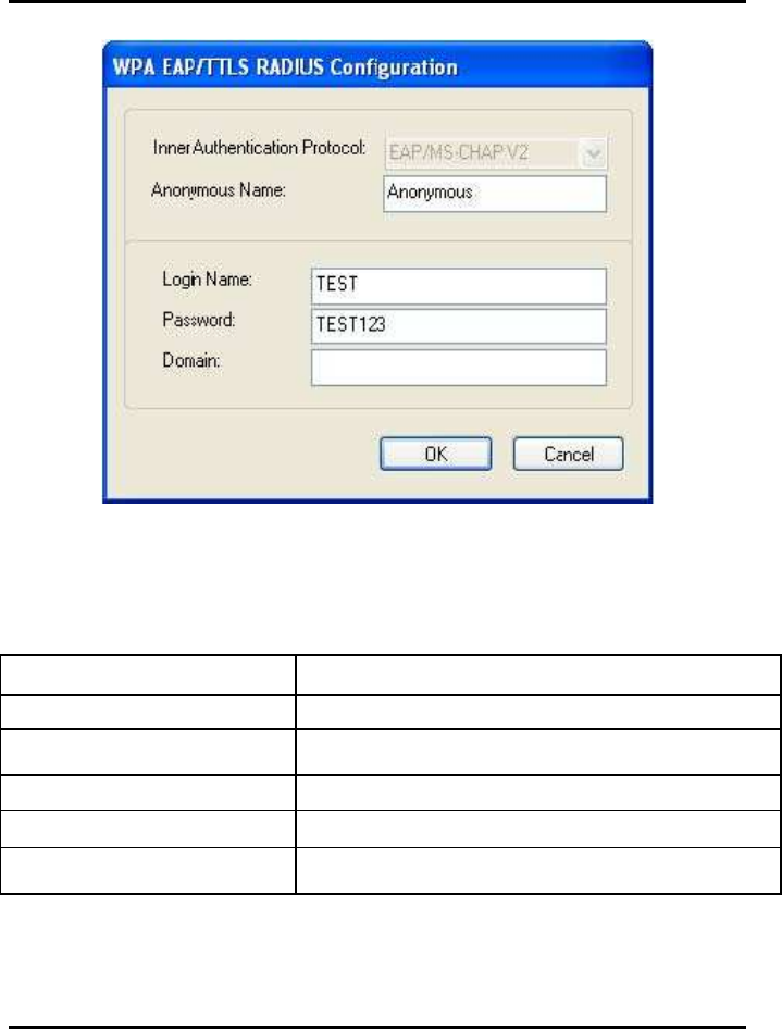
Clicking the Configure WPA RADIUS button displays the WPA EAP/TTLS
RADIUS Configuration window. Enter all the required information.
Appendix B Error Messages of Enabler Program
29
Figure 22:WPA EAP RADIUS Configuration window
Table 7: WPA TTLS RADIUS Configuration Window Description
Field Description
Inner Authentication Protocol Currently supports EAP/MS-CHAP V2 only
Anonymous Name Indicates the identity of the authentication server
with which to make contact
Login Name Login name to the RADIUS server
Password Password to login to the RADIUS server
Domain Domain name for login to the RADIUS server (op-
tional)
Click OK to set the configuration.
WM821-M MiniPCI Module —Using the
Wireless Utility
30
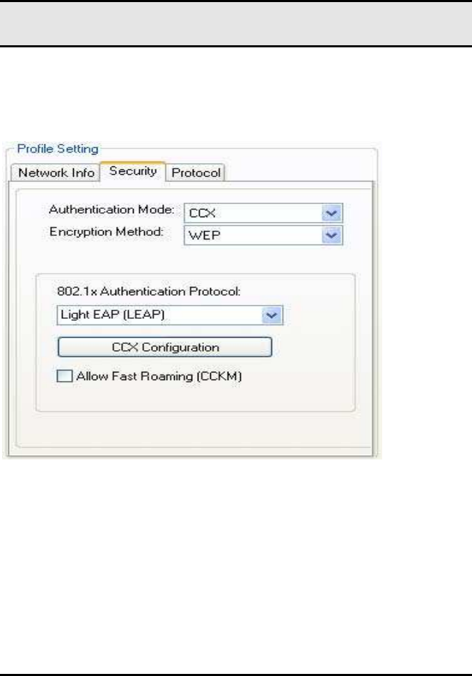
3.2.2.2.5 CCX EAP/LEAP
To connect to a Cisco AP through the RADIUS server, select CCX EAP/LEAP.
WEP is the Encryption Method, and the key is generated automatically.
Figure 23:
::
: Security Tab
Security TabSecurity Tab
Security Tab-
--
-CCX EAP/LEAP Authentication
CCX EAP/LEAP AuthenticationCCX EAP/LEAP Authentication
CCX EAP/LEAP Authentication
If Allow Fast Roaming (CCKM) is selected, Fast Roaming (Cisco Centralized
Key Management (CCKM)) is enabled.
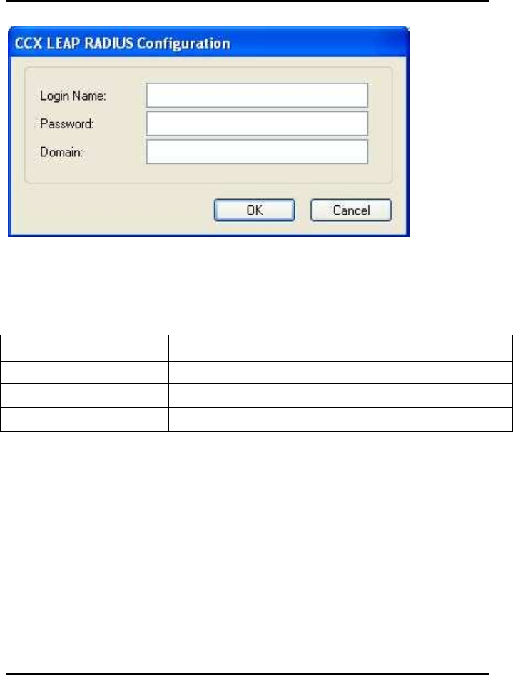
Clicking the CCX Configuration button displays the CCX LEAP RADIUS Configu-
ration window. Enter all the required information.
Appendix B Error Messages of Enabler Program
31
Figure 24:
::
: CCX E
CCX ECCX E
CCX EAP/LEAP RADIUS Configuration Window
AP/LEAP RADIUS Configuration WindowAP/LEAP RADIUS Configuration Window
AP/LEAP RADIUS Configuration Window
Table 8:
::
: CCX EAP/LEAP RADIUS Configuration Window Description
Field Description
Login Name Login name to the RADIUS server
Password Password to login to the RADIUS server
Domain Domain name for login to the RADIUS server (optional)
Click OK to set the configuration.
3.2.2.3 Encryption Methods
The following encryption methods are available, depending on the authentication
mode:
.
•
Security Off
.
•
WEP
.
•
TKIP
.
•
AES
3.2.2.4 WEP Key Settings
WM821-M MiniPCI Module —Using the
Wireless Utility
32
If the WEP Encryption Method is selected, the Security tab displays the WEP Key
Setting. To configure the WEP keys, select the WEP Key Setting, and click the
Configure WEP Keys button.
Note
The WEP key used for the transmission must be identical on the sending
and the receiving station.
Figure 25: Security Tab-WEP Key Settings
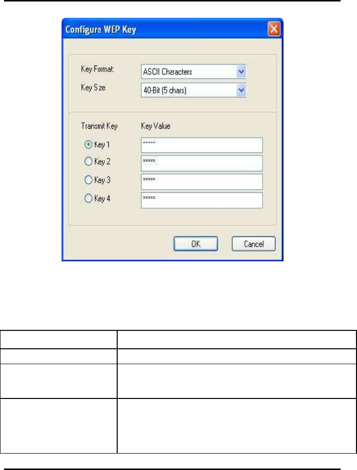
Clicking the Configure WEP Keys button displays the Configure WEP Key window.
Enter all the required information.
Appendix B Error Messages of Enabler Program
33
Figure 26: WEP Key Configuration Window
Table 9: WEP Key Configuration Window Description
Field Description
Key Format Either ASCII characters or hexadecimal digits
Key Size
•
40-bit, 5 character ASCII key size (40-bit, 10 character
hexadecimal)
•
104-bit, 13 character ASCII key size
(104-bit, 26 character hexadecimal)
Transmit Keys There are four transmit keys. The key value is in ASCII or
hexadecimal,
depending on the format selected. The WEP key size
shown depends on the key
size selected.
WM821-M MiniPCI Module —Using the
Wireless Utility
34
Click OK to set the configuration.
3.2.2.5 TKIP/AES Settings
If TKIP/AES is selected and the Authentication Mode is WPA-PSK or WPA2-PSK,
the security tab displays the TKIP/AES passphrase settings. Enter the passphrase
into the Passphrase and Confirm boxes, and click OK.
Figure 27: TKIP/AES Settings
Currently, only the functions WPA-PSK + TKIP and WPA2-PSK + AES are avail-
able. There is no such combination as WPA-PSK + AES or WPA2-PSK + TKIP.
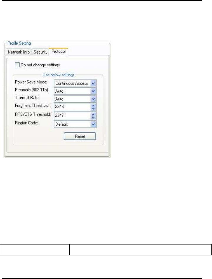
3.2.3 Profile Setting—Protocol Tab
Appendix B Error Messages of Enabler Program
35
The Protocol tab allows you to set or change the protocol information.
Figure 28:
::
:
Protocol Tab
DO NOT CHANGE SETTINGS
If this check box is selected, the protocol setting is not changed when the profile is
applied.
USE BELOW SETTINGS
If the Do not change setting check box is not se-
lected, the protocol settings include the following parameters.
Table 10:
::
: Protocol Tab Description
Field Description

WM821-M MiniPCI Module —Using the
Wireless Utility
36
Power Save Mode Sets the power mode. Available options are Continuous
Access or Max Power Save. The default setting is Con-
tinuous Access.
Preamble (802.11b) Sets the Radio Preamble to Auto, Short or Long. This
option takes effect only when attaching to an 802.11b
network.
Transmit Rate The range of the data rate depends on the type of AP
that the client card is connected to. The default setting is
Auto Select. MCS index will be allowed to select when
the 802.11n Network check box in the Network Info tab
is selected.
Fragment Threshold Sets the fragmentation threshold (the size that packets
are fragmented into for transmission). The default setting
is 2346.
Region Code Sets the region code. Available options are FCC (U.S.),
IC (Canada), ETSI (Europe), Spain, France, and MKK
(Japan).
RTS/CTS Threshold Sets the packet size at which the AP issues a Request-
To-Send (RTS) or Clear-to-Send (CTS) frame before
sending the packet. The default setting is 2347.
Reset Resets the protocol settings to their default values
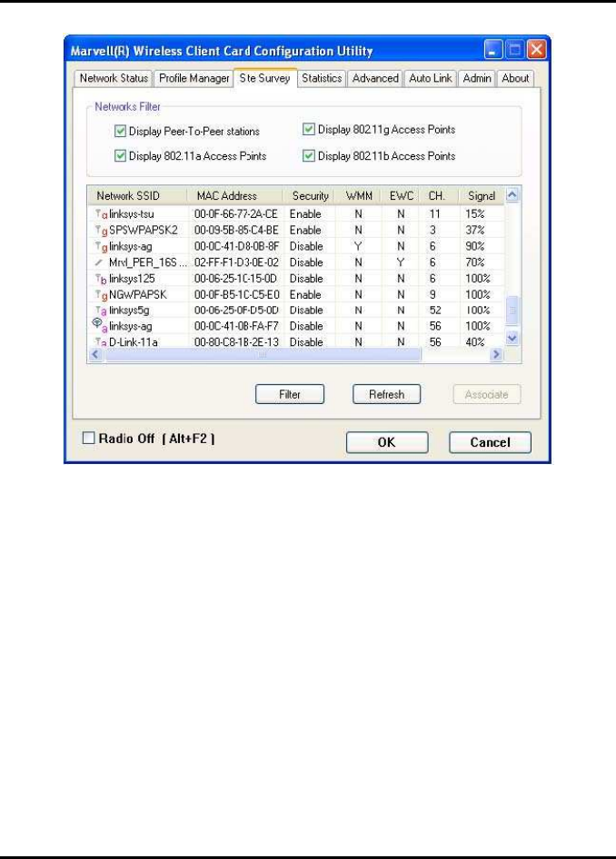
3.3 Site Survey Tab
Appendix B Error Messages of Enabler Program
37
Figure 29:
::
:
Site Survey Tab
3.3.1 Site Survey—Networks Filter
This section lets you customize which sites are displayed in the Site Survey list:
.
•
Display 802.11a Access Points
—
selecting this check box displays all
. 802.11a APs within range.
.
•
Display 802.11g Access Points
—
selecting this check box displays all
. 802.11g APs within range.
.
•
Display 802.11b Access Points
—
selecting this check box displays all
. 802.11b APs within range.
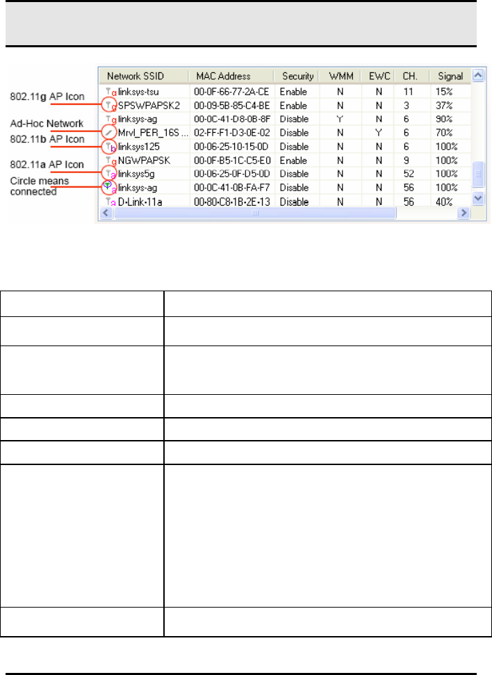
3.3.2 Site Survey—List of Detected Stations
This section reports information on the AP stations detected.
WM821-M MiniPCI Module —Using the
Wireless Utility
38
Figure 30: Site Survey-List of Detected Stations
Table 11: List of Detected Stations Description
Field Description
Network SSID Network SSID label (i.e., the Network Name). The Net-
work Name is a text string.
MAC Address MAC address, a hardware address that uniquely identi-
fies each node of a
network
Security Security enabled or disabled
CH Channel used by the detected device
Signal Signal strength of the detected device as a percentage
Icons The following icons may be displayed left of the Net-
work SSID:
•
An antenna icon with a subscript a
indicates an 802.11a AP.
•
An antenna icon with a subscript b indicates an
802.11b AP.
•
An antenna icon with a subscript g indicates an
802.11g AP.
•
A circle around the antenna icon means
the client card is connected to this
network.
WMM Wireless Multimedia Enhancements (WMM) supported
by the detected device
Appendix B Error Messages of Enabler Program
39
EWC Draft-802.11n/EWC functionality supported by the de-
tected device
Network Type Type of environment connected to Infrastructure
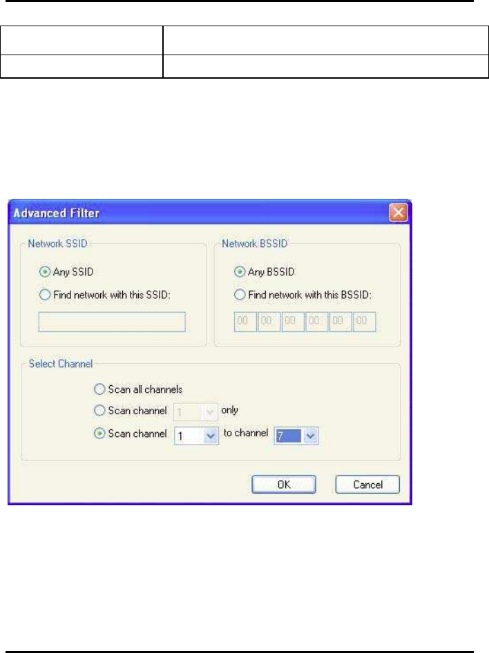
3.3.3 Site Survey—Filter Button
Clicking the Filter button displays the Advanced Filter window.
Figure 31:
Figure 36: Site Survey—Advanced Filter Window
3.3.3.1 Network SSID
.
•
Any SSID
—
no specific SSID is used when scanning for available net-
works in the area.

WM821-M MiniPCI Module —Using the
Wireless Utility
40
.
•
Find network with this SSID
—
the utility searches for the specified
SSID.
3.3.3.2 Network BSSID
.
•
Any BSSID
—
no specific BSSID is used when scanning for available
networks in the area.
.
•
Find network with this BSSID
—
the utility searches for the specified
BSSID.
3.3.3.3 Select Channel
.
•
Scan all channels
—
all channels are scanned when searching for
available networks in the area.
.
•
Scan channel Only
—
only the specified channel is scanned when
searching for available networks in the area.
.
•
Scan Channel to Channel
—
a range of channels are scanned when
searching for available networks in the area.
3.3.4 Site Survey—Refresh Button
Clicking the Refresh button requests a survey of the wireless
networks in the area.
3.3.5 Site Survey—Associate Button
Select an available network, and then click the Associate button to establish a con-
nection. Alternatively, the connection can be established by double-clicking the
selected network.
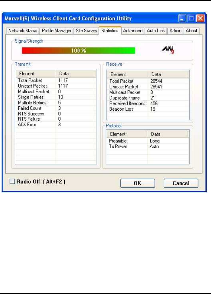
3.4 Statistics Tab
Clicking the Statistics tab displays the statistics
of the current connect session.
Appendix B Error Messages of Enabler Program
41
Figure 32:
Statistics Tab
3.4.1 Signal Strength
The color-coded Signal Strength bar displays the signal strength of the last packet
received by the client card. Signal strength is reported as a percentage. A signal in
the red indicates a bad connection. A signal in the green indicates a good connec-
tion.
3.4.2 Transmit Section
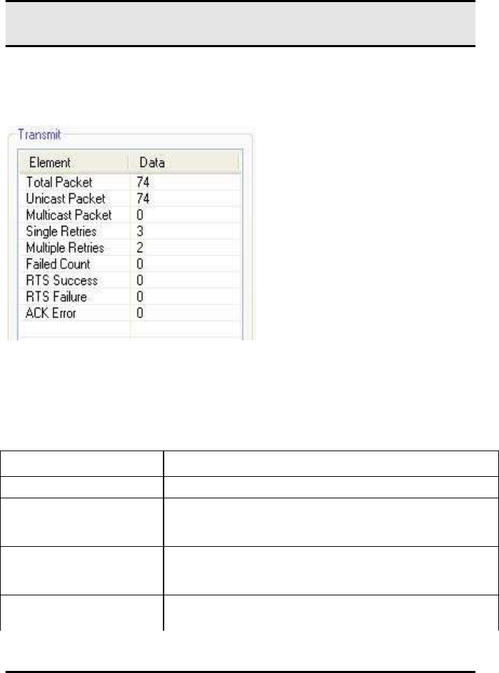
WM821-M MiniPCI Module —Using the
Wireless Utility
42
The Transmit section displays the information on the packets sent.
Figure 33:
Transmit Section
Table 12:
Transmit Section Description
Field Description
Total Packet Reports the total number of packets transmitted
Unicast Packet Reports the number of packets transmitted by the client
card that were destined
for a single network node
Multicast Packet Reports the number of packets transmitted by the client
card that were destined
for more than one network node
Single Retries Reports the number of packets that require one retry be-
fore the client card received an acknowledgement.
Appendix B Error Messages of Enabler Program
43
NOTE:After the client card sends a packet, it waits for an
acknowledge from the receiving radio to confirm that the
packet was successfully received. If the acknowledge is
not received within a specified period of time, the client
card retransmits the packet.
Multiple Retries Reports the number of packets that require more than
one retry before the client
card received an acknowledgement
Failed Count Reports the number of packets that were not successfully
transmitted because
the client card did not receive an acknowledge within the
specified period of time
RTS Success Reports the number of RTS attempts that were success-
ful
RTS Failure Reports the number of RTS attempts that were not suc-
cessful
ACK Error Reports the number of unicast transmit attempts for
which no acknowledgement
was received
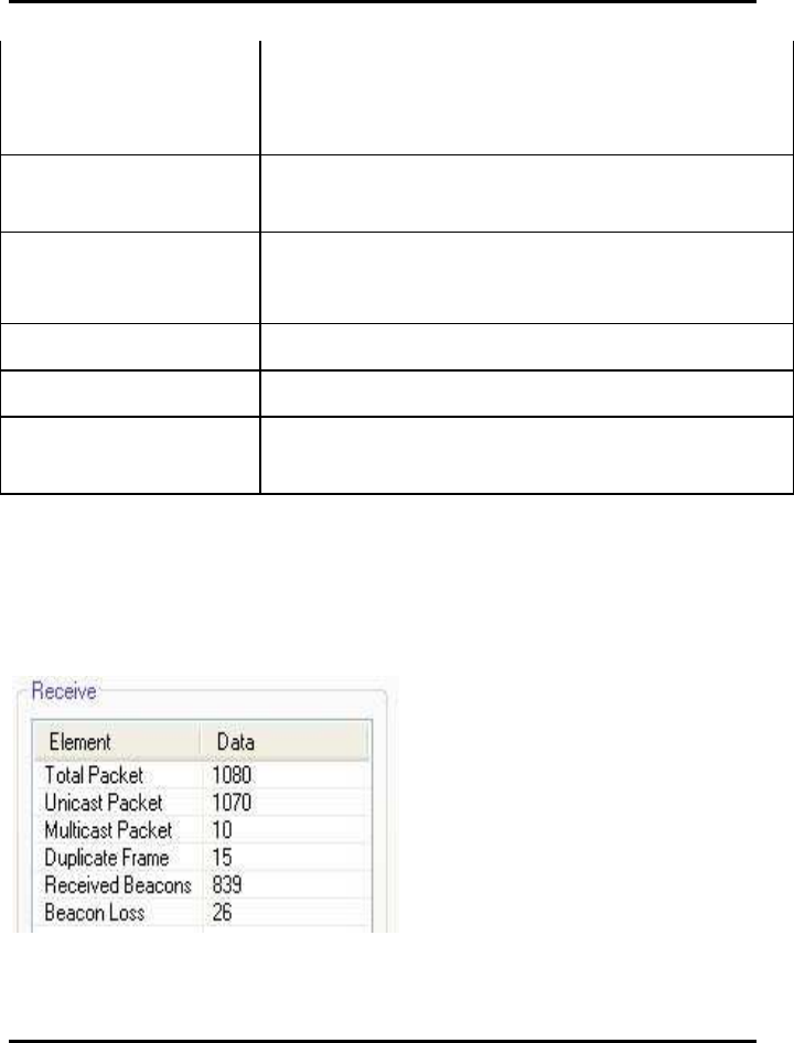
3.4.3 Receive Section
The Receive section displays the information on the packets received.
Figure 34:
Receive Section

WM821-M MiniPCI Module —Using the
Wireless Utility
44
Table 13:
Receive Section Description
Field Description
Total Packet Reports the total number of packets received
Unicast Packet Reports the number of packets received by the client
card that were destined for
a single network node
Multicast Packet Reports the number of packets received by the client
card that were destined for
more than one network node
Duplicate Frame Reports the number of duplicate frames received
Received Beacons Reports the number of beacons received after associa-
tion is established
Beacon Loss Reports the number of missing beacons after association
is established
3.4.4 Protocol Section
The Protocol section displays the information on the protocol status.
Figure 40:
Protocol Section

Appendix B Error Messages of Enabler Program
45
Figure 35:
Protocol Section
Table 14:
Protocol Section Description
Field Description
Preamble Displays radio preamble type:
•
Auto
•
Short
•
Long
Tx Power Displays transmit power mode:
•
Auto
•
High
•
Medium
•
Low
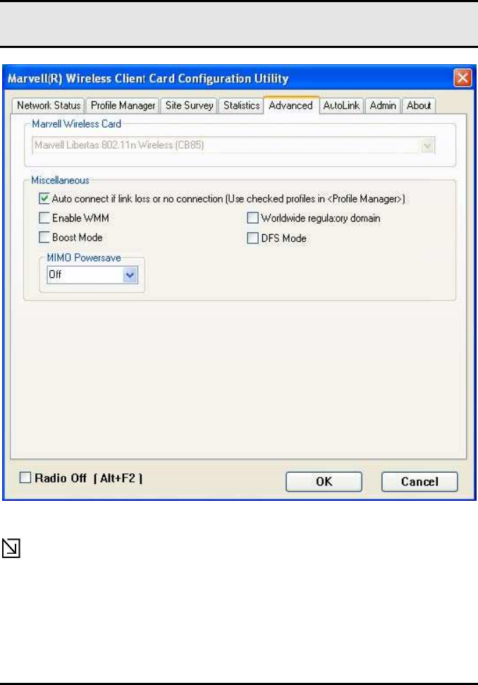
3.5 Advanced Tab
The Advanced tab displays the advanced parameters available for the installed
WM821-M client cards.
WM821-M MiniPCI Module —Using the
Wireless Utility
46
Figure 36:
Advanced Tab
Note The Advanced tab is not accessible when the Windows Zero Configura-
tion Utility is enabled.
3.5.1 Advanced Tab—WM821-M Wireless Card
Appendix B Error Messages of Enabler Program
47
This section of the Advanced tab reports the type of WM821-M client card installed.
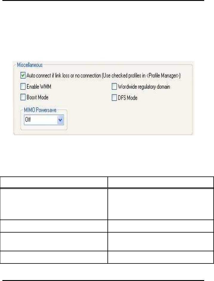
3.5.2 AdvancedTab—Miscellaneous
Figure 37: Miscellaneous Section
Table 15: Advanced Tab Miscellaneous Section Description
Field Description
Auto connect if link loss or no connection
(Use checked profiles in <Profile Man-
ager>)
Clear this check box to disable the auto-
configuration feature. Whenever there is
a link loss, auto-configuration tries to
establish a connection to the checked
profiles in the Profile Manager window.
Boost Mode Select this check box for performance
enhancement.
Enable WMM Select this check box to enable/disable
the Wireless Multimedia Enhancements
(WMM) feature.
Worldwide regulatory domain Select this check box to set the regula-
tory domain
WM821-M MiniPCI Module —Using the
Wireless Utility
48
DFS Mode Select this check box to enable Dynamic
Frequency Selection (DFS)
MIMO Powersave Enables/disables the Multiple Input Multi-
ple Output (MIMO) Powersave Mode.
Available options are Off and Static.
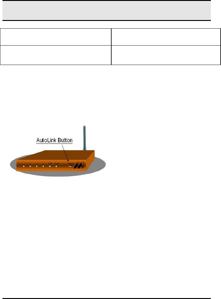
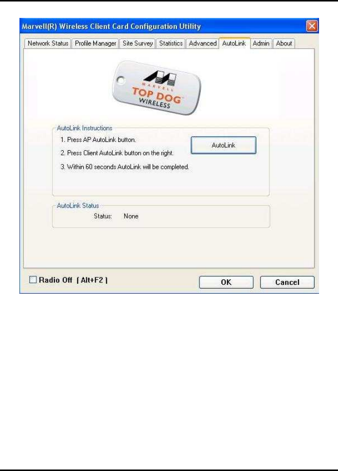
3.6 AutoLink Tab
To enable AutoLink mode, proceed as follows:
1. 1. Toggle the AutoLink button on the Access Point to enable AutoLink mode.
2. 2. Toggle the AutoLink button on the client to enter AutoLink mode.
Figure 38: Access Point Autolink Button
Within 60 seconds, the AutoLink will be completed.
Appendix B Error Messages of Enabler Program
49
Figure 39: Auto Link Tab (Client)
AutoLink is complete.
WM821-M MiniPCI Module —Using the
Wireless Utility
50
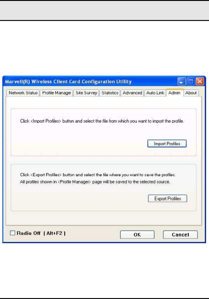
3.7 Admin Tab
The Admin tab allows you to import and export profiles.
Figure 40:
Admin Tab
3.7.1 Admin Tab—Import Profiles

Appendix B Error Messages of Enabler Program
51
To import a profile, proceed as follows:
1. 1. Click Import Profiles.
2. 2. Select the path and filename of the profile.
3. 3. Click Open.
3.7.2 Admin Tab—Export Profiles
To export a profile, proceed as follows:
1. 1. Click Export Profiles.
2. 2. Select or enter the path and filename of the profile.
3. 3. Click Save.
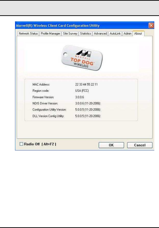
3.8 About Tab
The About tab displays information about the WM821-M Client
Card Configuration Utility.
WM821-M MiniPCI Module —Using the
Wireless Utility
52
Figure 41:
About Tab

53
Appendix A
Specifications
Specifications
Product Name Draft 802.11n-
compatible Dual Band WLAN mPCI
Card
Interface mPCI 32 Type III-B
Network Standards IEEE802.11a/g/b Draft n-compliant
54, 48, 36, 24, 18, 12, 9, 6, 11, 5.5, 2,1Mbps
20MHz BW: 130, 117, 104, 78, 52, 39, 26 and
13Mbps
Data Rate
40MHz BW: 300, 270, 243, 216, 162, 108, 81, 54
and 27Mbps
802.11a/g/n---- 54, 48, 36,24,18,12,9,6Mbps
(OFDM)
Modulation 802.11b ---- CCK (11Mbps, 5.5Mbps), QPSK
(2Mbps), BPSK (1Mbps)
2.412 ~ 2.462 GHz: North America
2.412 ~ 2.472 GHz: Europe ETSI
2.412 ~ 2.472 GHz: Japan (ARIB STD-T66)
5.15 ~ 5.35GHz/ 5.47 ~ 5.825 GHz: North Amer-
ica UNII
5.15 ~ 5.35GHz/ 5.47 ~ 5.725GHz: Europe ETSI
Operating Frequency
4.9 ~ 5.0GHz/ 5.15 ~ 5.35GHz: Japan (TBD)
11g: 1~11 for America,1~13 for Europe (ETSI)
and Japan (ARIB STD-66)
Operating Channels
11b: 1~11 for America,1~13 for Europe
(ETSI),1~14 for Japan

WM821-M MiniPCI Module —Using the
Wireless Utility
54
11a: 36-64, 100-161 North America; 36-64 for
Japan and other ch definitions
(TBD) 12 dBm (5GHz), 15dBm (2.4GHz)
(54Mbps, OFDM, typical)
RF Output Power
(TBD)18 dBm (2.4GHz, 11Mbps, CCK, typical)
Antenna Three IPEX connectors with diversity for external
antenna
Power LED: GPIO control
LED Indicators
Link LED: GPIO control
Indoor: 20M@54Mbps, 35M@24Mbps,
60M@6Mbps, 100M@11Mbps
Coverage Area Outdoor: 50M@54Mbps, 65M@48Mbps,
90M@36Mbps, 120M@24,18,12,9,6Mbps,
80M@11Mbps, 120M@5.5Mbps, 200M@2Mbps,
300M@1Mbps
-70 dBm @ 54M (OFDM, 10% PER)
Receiver Sensitivity
-86 dBm @ 11M (CCK, 8% PER)
TX power consumption: <680mA @3.3V
Power Consumption
RX power consumption: <670mA @3.3V
Support OS Linux, Microsoft Windows Windows 2K, Windows
XP (TBD)
Operating Temperature 0 to 55 ℃
Humidity 20% to 95% Non-condensing
Dimensions (mm) (W) 59.6mm × (D) 44.45mm × (H) 4.9mm
Weight (g) 28 g
Voltage 3.3V