CyberTAN Technology WU172HS WLAN Module User Manual
CyberTAN Technology Inc. WLAN Module Users Manual
UserManual.wiki
>
CyberTAN Technology
>
WU172HS User Manual
Users Manual
Navigation menu
Upload a User Manual
Namespaces
Wiki Guide
HTML
PDF
Info
Views
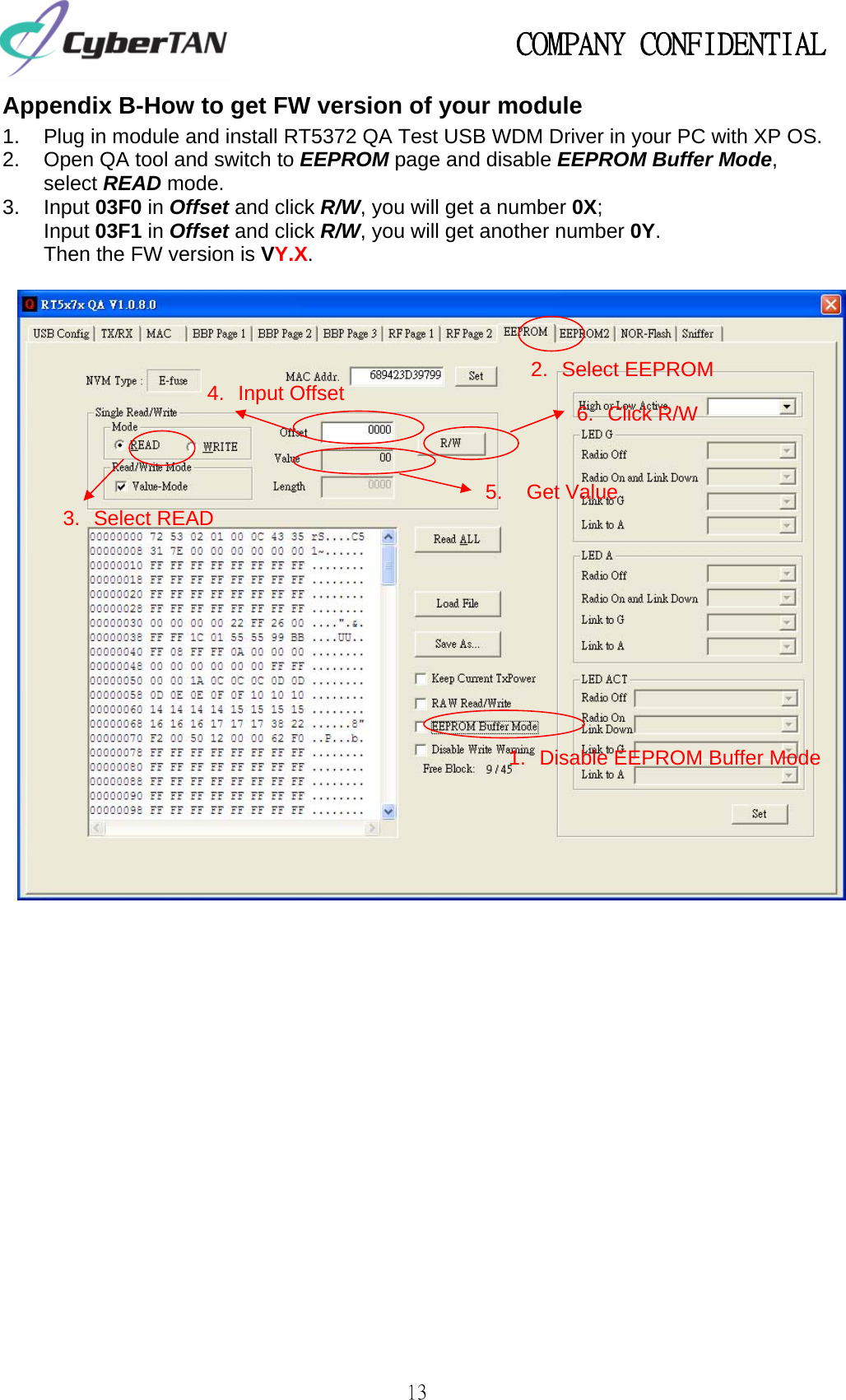
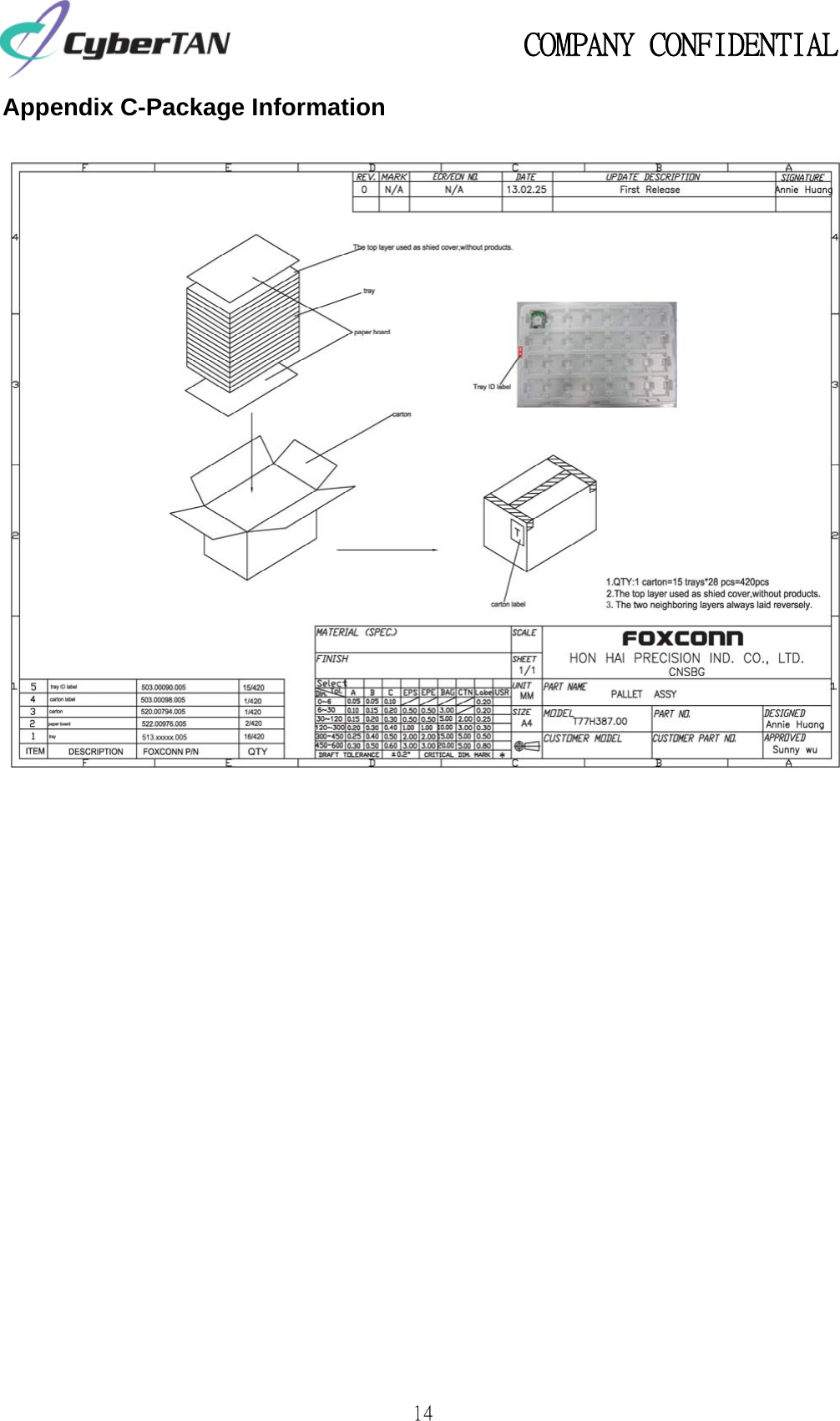
User Manual
Discussion / Help
Navigation