CyberTAN Technology WU172HS WLAN Module User Manual
CyberTAN Technology Inc. WLAN Module Users Manual
Users Manual
COMPANY CONFIDENTIAL
1
IEEE 802.11b/g/n 2T2R USB WiFi Module
Project Name 11n USB WiFi Module with RT5372L
CyberTan Part No T77H387.00
Customer Hisense
Customer Part No. 1127000
CyberTan Model Name WU172HS
Product Specification
CyberTAN Technology, Inc
99 Park Avenue III,
Science Park Hsin chu 308,
Taiwan.
TEL:+886-3-577-7777
Fax:+886-3-577-77880

COMPANY CONFIDENTIAL
2
Content
0. REVISION HISTORY ........................................................................ 3
1. INTRODUCTION ........................................................................... 4
1.1
RF
MODULE
O
VERVIEW
..................................................................... 4
1.2
S
PECIFICATION REFERENCE
.................................................................. 4
1.3
S
YSTEM
F
UNCTIONS
........................................................................ 5
2. MECHANICAL SPECIFICATION ............................................................. 6
2.1
M
ECHANICAL
O
UTLINE
D
RAWING
.............................................................. 6
2.2
WTB
CONNECTOR
P
IN DEFINITION
.......................................................... 6
3. ELECTRICAL SPECIFICATION .............................................................. 7
3.1
O
PERATING
C
ONDITION
..................................................................... 7
3.2
W
I
F
I
RF
S
PECIFICATION
(@5V/25℃) .......................................................... 7
3.2.1 802.11b Mode
........................................................................ 7
3.2.2 802.11g Mode
........................................................................ 8
3.2.3 802.11n HT20 Mode
.................................................................. 8
3.2.4 802.11n HT40 Mode
.................................................................. 9
3.3
O
N
-
BOARD
A
NTENNA
S
PECIFICATION
.......................................................... 10
4. QUALITY ................................................................................. 11
5. APPENDIX ............................................................................... 12
A
PPENDIX
A-L
ABEL
I
NFORMATION
............................................................... 12
A
PPENDIX
B-H
OW TO GET
FW
VERSION OF YOUR MODULE
............................................ 13
A
PPENDIX
C-P
ACKAGE
I
NFORMATION
............................................................ 14
A
PPENDIX
D-F
EDERAL
C
OMMUNICATION
C
OMMISSION
I
NTERFERENCE
S
TATEMENT
........................ 15
COMPANY CONFIDENTIAL
3
0. Revision History
Date Document
revision Product
revision Change Description
2013/01/28 00 005 1. Initial release(preliminary),
2013/02/18 01 005 1. Remove I-PEX RF connector
2013/03/01 02 005
1. Update the power consumption and RF
performance at section3.
2. Add package information at section5
2013/03/20 03 015 1. Update the sample picture.
2. Add the antenna’s performance
2013/06/03 04 015
1. Change 11b power from 16dBm to 13dBm to
pass CE and C-tick certification
2. Change FW ver to V2.0
2013/08/05 05 015
1. Add customer PN
2. Update Label information(add CE and C-tick
logo)
3. Update sample photo
2014/01/14 06 015
1. Add FCC Federal Communication
Commission Interference Statement
2. Update working frequency to meet FCC
Regulation
COMPANY CONFIDENTIAL
4
1. Introduction
Project Name: 11n USB WiFi Module with RT5372L
Project Number: T77H387.00
This documentation describes the engineering requirements specification of WiFi module
with RT5372. It is a confidential document of CyberTan.
1.1 RF module Overview
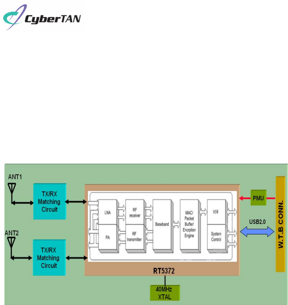
The general HW architecture for the module is shown in Figure 1. This WLAN Module
design is based on Ralink RT5372L. It is a highly integrated single-chip MIMO (Multiple In
Multiple Out) Wireless LAN (WLAN) USB2.0 network interface controller complying with
the 802.11n specification. It combines a MAC, a 2T2R capable baseband, and RF in a
single chip. The RT5372 provides a complete solution for a high throughput performance
wireless client.
Figure 1 Module Block Diagram
1.2 Specification reference
This specification is based on additional references listed below.
z IEEE Std. 802.11b
z IEEE Std. 802.11g
z IEEE Std. 802.11n
COMPANY CONFIDENTIAL
5
1.3 System Functions
Table1: General Specification as below:
Main Chipset Mediatek RT5372L
Operating Frequency 2.412~2.462GHz
WiFi Standard 802.11b/g/n(2x2)
FW version V2.0
(To read this version, refer to
Appendix B
)
Modulation 11b: DBPSK, DQPSK and CCK and DSSS
11g: BPSK, QPSK, 16QAM, 64QAM and OFDM
11n: MCS0~15 OFDM
PHY Data rates 11b:1, 2, 5.5 and 11Mbps
11g:6, 9, 12, 18, 24, 36, 48 and 54 Mbps
11n: MCS0~15, up to 300Mbps
Form factor 5pin side entry type WTB CONN, 1.25mm pitch,
Host Interface USB 2.0
PCBA Dimension Typical,40mm(W)*46.45mm(L)*5mm(T)
(The height including WTB connector and antenna)
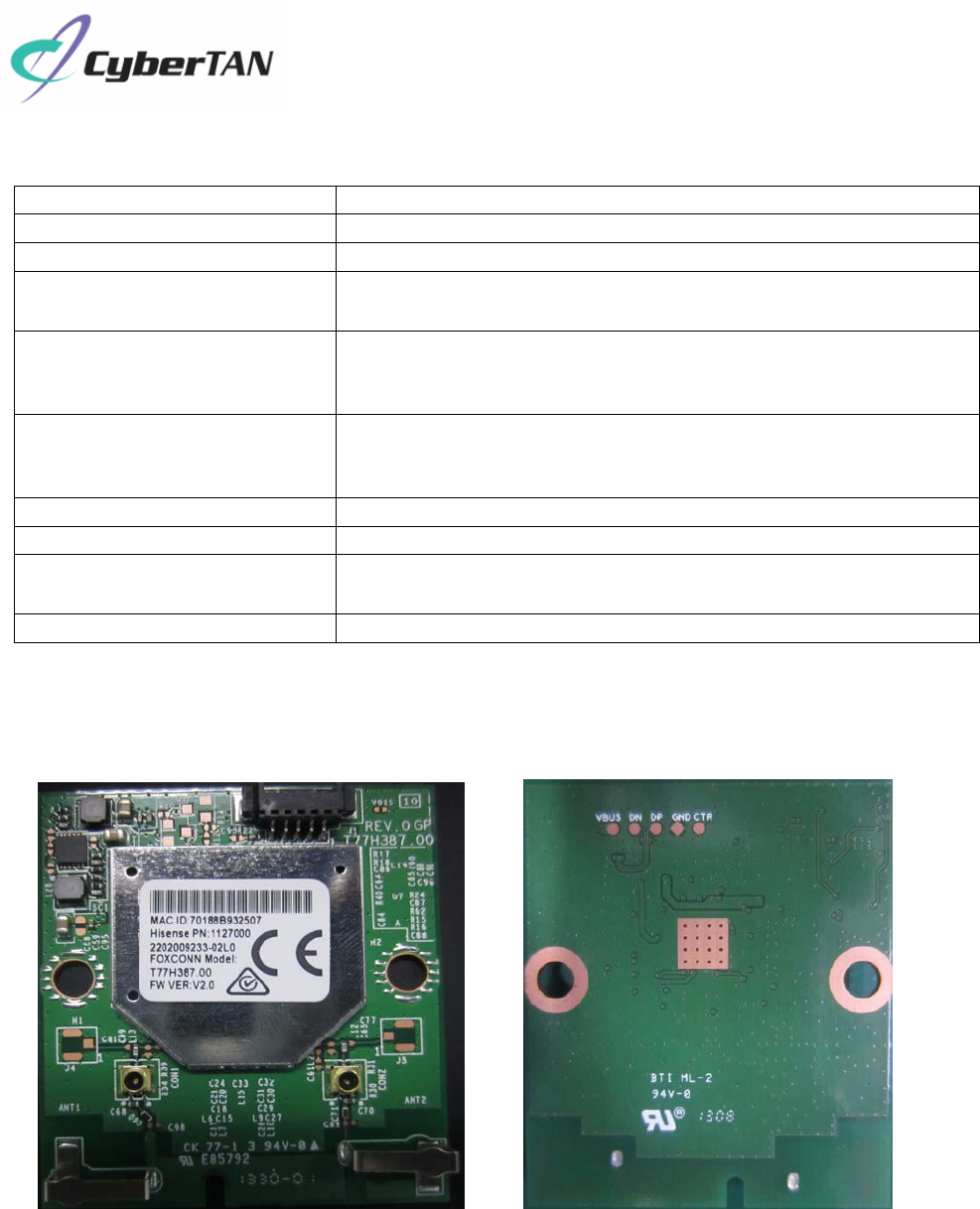
Antenna Two Metal Antennas on-board design
Sample picture as bellow
TOP VIEW BOTTOM VIEW
* note1, the sample picture is just for reference only.
COMPANY CONFIDENTIAL
6
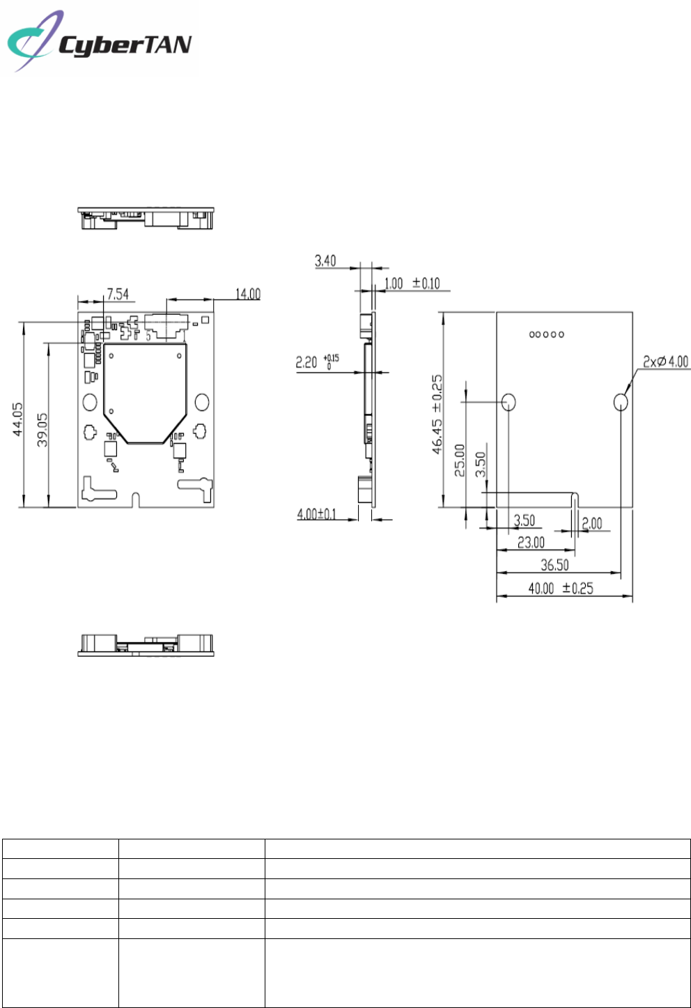
2. Mechanical Specification
2.1 Mechanical Outline Drawing
Typical Dimension (W x L): 40.00mmx 46.45mm.
2.2 WTB CONNECTOR Pin definition
z 5Pin, 1.25mm pitch, SMD, side entry type.
z Pin No. of WTB connector is remarked in PCBA ME drawing on above item2.1.
Pin # Name Description
1 VBUS 5V DC power supply input
2 D- USB Data DN
3 D+ USB Data DP
4 GND Ground
5 CTR WLAN Radio on/off control
LowÆDisable module.
HighÆNormal working mode.
(Module internally pull-high to 3.3V,no need for external pull-high)
Unit: mm
COMPANY CONFIDENTIAL
7
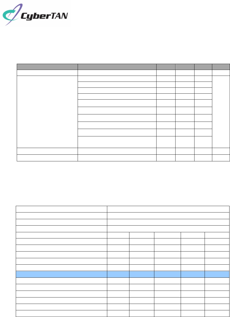
3. Electrical Specification
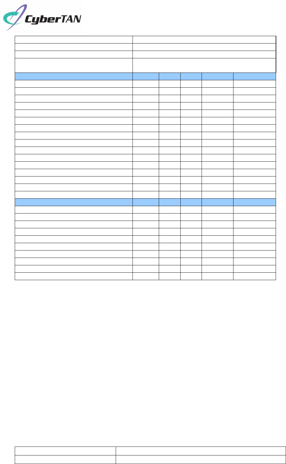
3.1 Operating Condition
Parameter Condition Min. Typ. Max. Unit
DC power input --- 4.5 5.0 5.5 V
DC Current (Average.)
@5V power input
11b TX throughput mode - 300 500
mA
11b RX throughput mode - 159 500
11g TX throughput mode - 276 500
11g RX throughput mode - 156 500
11n-HT20 TX throughput mode - 358 500
11n-HT20 RX throughput mode - 164 500
11n-HT40 TX throughput mode - 350 500
11n-HT40 RX throughput mode - 203 500
Power down mode(CTR pull-low) - 35 500
Standby mode , not connected
with AP. - 78 500
Operating Temperature -- 0 +60 ℃
Storage Temperature -- -40 +85 ℃
3.2 WiFi RF Specification(@5V/25℃)
3.2.1 802.11b Mode
Items Contents
Mode IEEE802.11b
Channel CH1 to CH11
Data rate 1, 2, 5.5, 11Mbps
1. Target Power Levels (*note2)
1) 11b Output power 11 13 14 dBm
2. Spectrum Mask @ target power
1) fc +/-11MHz to +/-22MHz - -48 -30 dBr
2) fc > +/-22MHz - -58 -50 dBr
3. Frequency Error -15 -1 +15 ppm
RX Characteristics(per each chain) Min. Typ. Max. Unit
4 Minimum Input Level Sensitivity
1) 1Mbps (FER≦8%) - -96
-88 dBm
2) 2Mbps (FER≦8%) - 95
-85 dBm
3) 5.5Mbps (FER≦8%) - -92
-83 dBm
4) 11Mbps (FER≦8%) - -89
-80 dBm
5 Maximum Input Level (FER≦8%) -10 - dBm
COMPANY CONFIDENTIAL
8
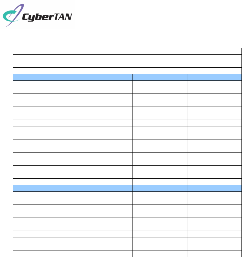
3.2.2 802.11g Mode
Items Contents
Mode IEEE802.11g
Channel CH1 to CH11*
Data Rate 6, 9, 12, 18, 24, 36, 48, 54Mbps
TX Characteristics (per each chain) Min. Typ. Max. Unit
1. Target Power Levels (*note2)
1) 11g Output power 13 15 16.5 dBm
2. Spectrum Mask @ target power
1) at fc +/- 11MHz - -43 -20 dBr
2) at fc +/- 20MHz - -44 -28 dBr
3) at fc > +/-30MHz - -54 -40 dBr
3 Constellation Error(EVM)@ target power
1) 6Mbps - - -5 dB
2) 9Mbps - - -8 dB
3) 12Mbps - - -10 dB
4) 18Mbps - - -13 dB
5) 24Mbps - - -16 dB
6) 36Mbps - - -19 dB
7) 48Mbps - - -22 dB
8) 54Mbps - -30 -25 dB
4 Frequency Error -15 -1.1 +15 ppm
RX Characteristics (per each chain) Min. Typ. Max. Unit
5 Minimum Input Level Sensitivity
1) 6Mbps (PER ≦ 10%) - -91 -85 dBm
2) 9Mbps (PER ≦ 10%) - -90 -84 dBm
3) 12Mbps (PER ≦ 10%) - -88 -82 dBm
4) 18Mbps (PER ≦ 10%) - -86 -80 dBm
5) 24Mbps (PER ≦ 10%) - -83 -77 dBm
6) 36Mbps (PER ≦ 10%) - -81 -73 dBm
7) 48Mbps (PER ≦ 10%) - -77 -69 dBm
8) 54Mbps (PER ≦ 10%) - -75 -68 dBm
6 Maximum Input Level (PER ≦ 10%) -20 - dBm
3.2.3 802.11n HT20 Mode
COMPANY CONFIDENTIAL
9
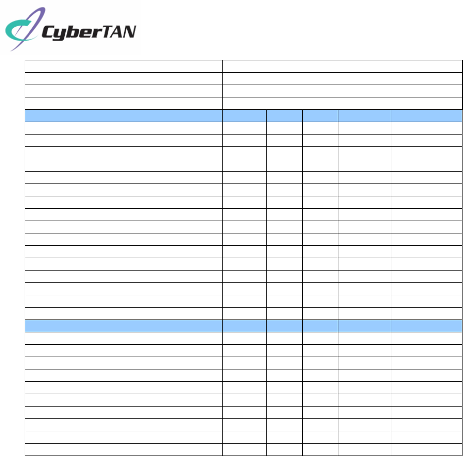
3.2.4 802.11n HT40 Mode
Items Contents
Mode IEEE802.11n HT20 @ 2.4GHz
Channel CH1 to CH11*
Data Rate MCS0/1/2/3/4/5/6/7/8/9/10/11/12/13/14/15,up to 150Mbps
TX Characteristics
(
per each chain
)
Min. Typ. Max. Unit
1. Target Power Levels (*note2)
1) 11n-HT20 Output power
13 15 16.5
dBm
2. Spectrum Mask @ target power
1) at fc +/- 11MHz - -38 -20 dBr
2) at fc +/- 20MHz - -43 -28 dBr
3) at fc > +/-30MHz - -53 -45 dBr
3. Constellation Error(EVM)@ target power
1) MCS0 - -
-5 dB
2) MCS1 - -
-10 dB
3) MCS2 --
-13 dB
4) MCS3 - -
-16 dB
5) MCS4 - -
-19 dB
6) MCS5 --
-22 dB
7) MCS6 - -
-25 dB
8) MCS7 - -32
-28 dB
4. Frequency Error -15 -1.2 +15 ppm
RX Characteristics
(
per each chain
)
Min. Typ. Max. Unit
5. Minimum Input Level Sensitivity
1) MCS0 (PER ≦ 10%) - -89 -82 dBm
2) MCS1 (PER ≦ 10%) - -88 -79 dBm
3) MCS2 (PER ≦ 10%) - -86 -77 dBm
4) MCS3 (PER ≦ 10%) - -83 -74 dBm
5) MCS4 (PER ≦ 10%) - -80 -70 dBm
6) MCS5 (PER ≦ 10%) - -76 -66 dBm
7) MCS6 (PER ≦ 10%) - -74 -65 dBm
8) MCS7 (PER ≦ 10%) - -72 -64 dBm
6. Maximum Input Level (PER ≦ 10%) -20 - dBm
COMPANY CONFIDENTIAL
10
*note2: the target power level will be changed later based-on regulatory testing result.
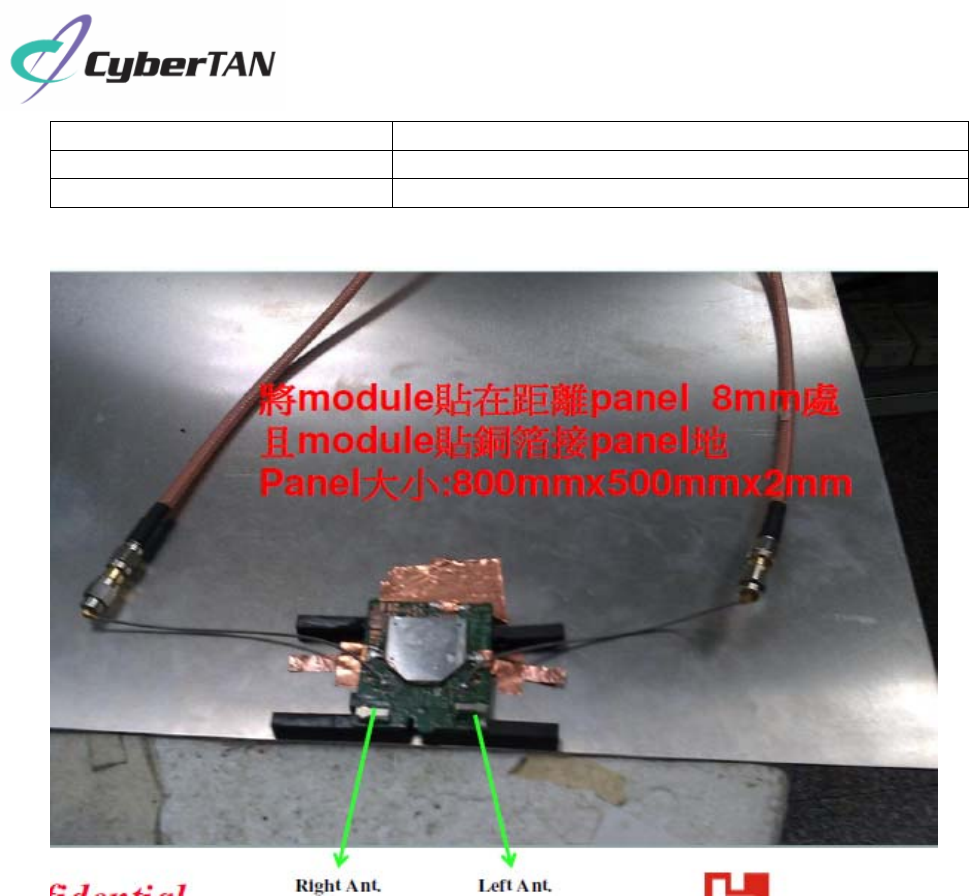
3.3 On-board Antenna Specification
Operating Frequency 2.412~2.472GHz
VSWR(max) <=2.5:1
Items Contents
Mode IEEE802.11n HT40 @ 2.4GHz
Channel CH3 to CH9
Data Rate
MCS0/1/2/3/4/5/6/7/8/9/10/11/12/13/14/15,
up to 300Mbps
TX Characteristics
(
per each chain
)
Min. Typ. Max. Unit
1. Target Power Levels (*note2)
1) 11n-HT20 Output power
12 14 15.5
dBm
2. Spectrum Mask @ target power
1) at fc +/- 11MHz - -37 -20 dBr
2) at fc +/- 20MHz - -40 -28 dBr
3) at fc > +/-30MHz - -50 -45 dBr
3. Constellation Error(EVM)@ target power
1) MCS0 - -
-5 dB
2) MCS1 - -
-10 dB
3) MCS2 --
-13 dB
4) MCS3 - -
-16 dB
5) MCS4 - -
-19 dB
6) MCS5 --
-22 dB
7) MCS6 - -
-25 dB
8) MCS7 - -32
-28 dB
4. Frequency Error -15 -1.3 +15 ppm
RX Characteristics
(
per each chain
)
Min. Typ. Max. Unit
5. Minimum Input Level Sensitivity
1) MCS0 (PER ≦ 10%) - -88 -79 dBm
2) MCS1 (PER ≦ 10%) - -85 -76 dBm
3) MCS2 (PER ≦ 10%) - -83 -74 dBm
4) MCS3 (PER ≦ 10%) - -80 -71 dBm
5) MCS4 (PER ≦ 10%) - -77 -67 dBm
6) MCS5 (PER ≦ 10%) - -72 -63 dBm
7) MCS6 (PER ≦ 10%) - -71 -62 dBm
8) MCS7 (PER ≦ 10%) - -68 -61 dBm
6. Maximum Input Level (PER ≦ 10%) -20 - dBm
COMPANY CONFIDENTIAL
11
Isolation >=10dB
Peak Gain 2.80dBi
Antenna Type Metal
*note: the antenna performance is measured based-on below test setup environment.
4. Quality
The product quality must be followed-up by CyberTan factory quality control system.
COMPANY CONFIDENTIAL
12
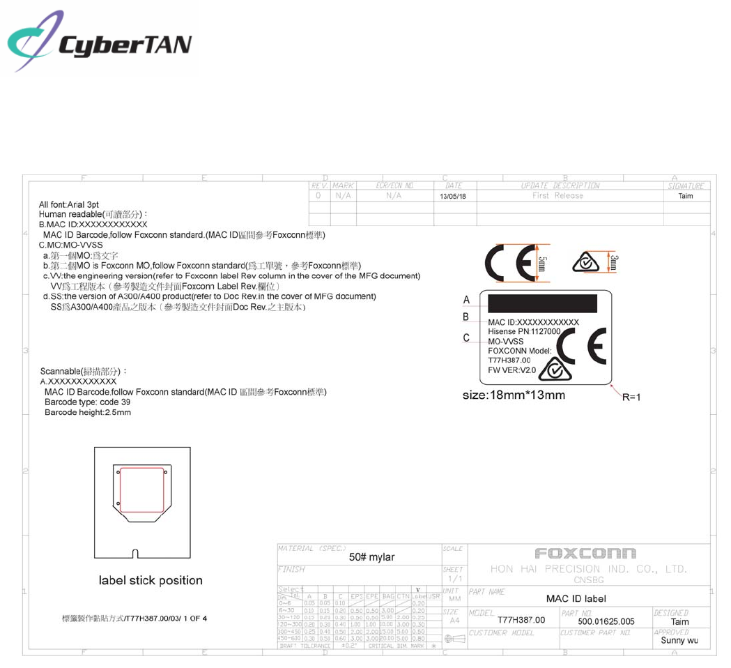
5. Appendix
Appendix A-Label Information
COMPANY CONFIDENTIAL
13
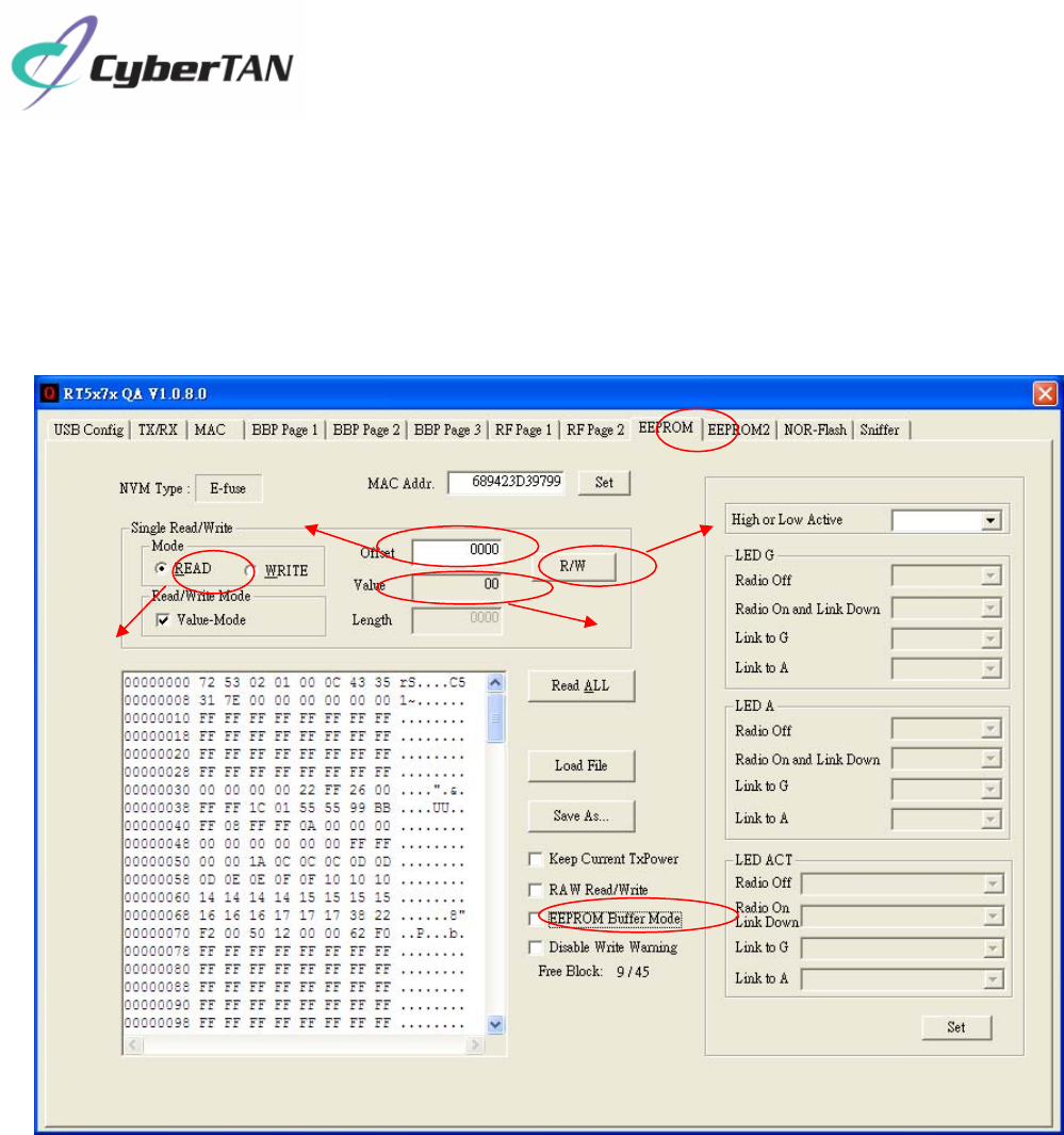
Appendix B-How to get FW version of your module
1. Plug in module and install RT5372 QA Test USB WDM Driver in your PC with XP OS.
2. Open QA tool and switch to EEPROM page and disable EEPROM Buffer Mode,
select READ mode.
3. Input 03F0 in Offset and click R/W, you will get a number 0X;
Input 03F1 in Offset and click R/W, you will get another number 0Y.
Then the FW version is VY.X.
4. Input Offset 2. Select EEPROM
1. Disable EEPROM Buffer Mode
3. Select READ
6. Click R/W
5. Get Value
COMPANY CONFIDENTIAL
14
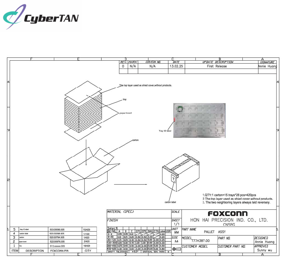
Appendix C-Package Information

COMPANY CONFIDENTIAL
15
Appendix D-Federal Communication Commission Interference
Statement
This equipment has been tested and found to comply with the limits for a Class B digital device,
pursuant to Part 15 of the FCC Rules. These limits are designed to provide reasonable protection
against harmful interference in a residential installation. This equipment generates, uses and can
radiate radio frequency energy and, if not installed and used in accordance with the instructions,
may cause harmful interference to radio communications. However, there is no guarantee that
interference will not occur in a particular installation. If this equipment does cause harmful
interference to radio or television reception, which can be determined by turning the equipment off
and on, the user is encouraged to try to correct the interference by one of the following measures:
- Reorient or relocate the receiving antenna.
- Increase the separation between the equipment and receiver.
- Connect the equipment into an outlet on a circuit different from that to which the receiver is
connected.
- Consult the dealer or an experienced radio/TV technician for help.
FCC Caution:
Any changes or modifications not expressly approved by the party responsible for compliance could
void the user's authority to operate this equipment. This device complies with Part 15 of the FCC
Rules. Operation is subject to the following two conditions:
(1) This device may not cause harmful interference, and
(2) This device must accept any interference received, including interference that may cause
undesired operation.
FCC Radiation Exposure Statement:
This equipment complies with FCC radiation exposure limits set forth for an uncontrolled
environment. This transmitter module must not be co-located or operating in conjunction with any
other antenna or transmitter. This End equipment should be installed and operated with a minimum
distance of 20 centimeters between the radiator and your body.
IMPORTANT NOTE:
In the event that these conditions can not be met (for example certain laptop configurations or
co-location with another transmitter), then the FCC authorization is no longer considered valid and
the FCC ID can not be used on the final product. In these circumstances, the OEM integrator will be
responsible for re-evaluating the end product (including the transmitter) and obtaining a separate
FCC authorization.
End Product Labeling
The final end product must be labeled in a visible area with the following: “Contains FCC ID:
N89-WU172HS”.
Manual Information to the End User
The OEM integrator has to be aware not to provide information to the end user regarding how to
install or remove this RF module in the user’s manual of the end product which integrates this
module.