CyberTAN Technology WU322HS WLAN Module User Manual 802
CyberTAN Technology Inc. WLAN Module 802
UserManual.wiki
>
CyberTAN Technology
>
WU322HS User Manual
User Manual
Navigation menu
Upload a User Manual
Namespaces
Wiki Guide
HTML
PDF
Info
Views
User Manual
Discussion / Help
Navigation
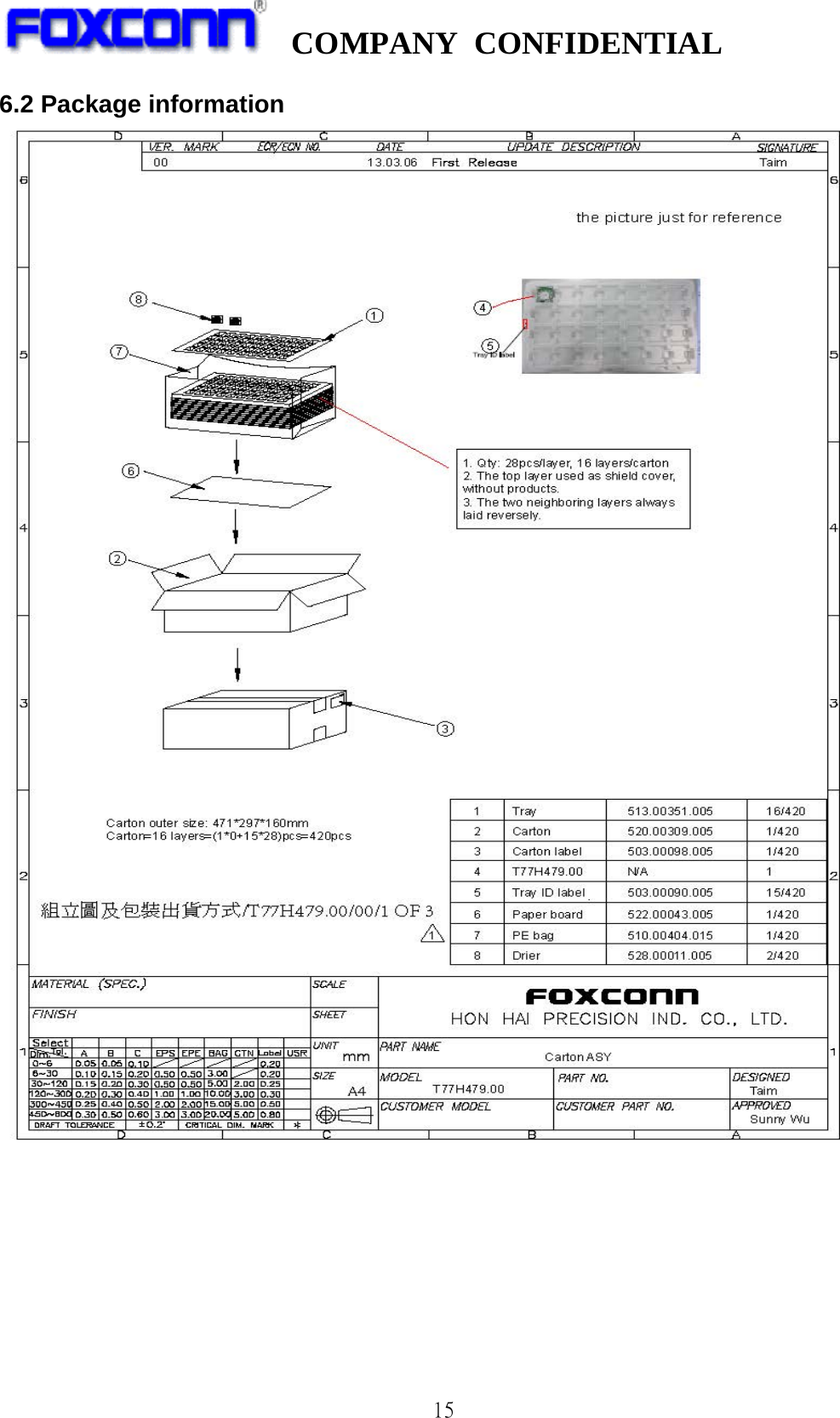
![COMPANY CONFIDENTIAL 2 Content 0. REVISION HISTORY ............................................................................ 3 1. INTRODUCTION ............................................................................... 4 1.1 RF MODULE OVERVIEW......................................................................... 4 1.2 SPECIFICATION REFERENCE ..................................................................... 4 1.3 SYSTEM FUNCTIONS ........................................................................... 5 2. MECHANICAL SPECIFICATION ................................................................. 6 2.1 MECHANICAL OUTLINE DRAWING ................................................................. 6 2.2 WTB CONNECTOR PIN DEFINITION ............................................................. 6 3. ELECTRICAL SPECIFICATION .................................................................. 7 3.1 802.11B MODE ............................................................................... 7 3.2 802.11G MODE ............................................................................... 8 3.3 802.11N 2.4G HT20 MODE ..................................................................... 9 3.4 802.11N 2.4G HT40 MODE .................................................................... 10 3.5 802.11A MODE .............................................................................. 11 3.6 802.11N 5G HT20 MODE ...................................................................... 12 3.7 802.11N 5G HT40 MODE ...................................................................... 13 4 SOFTWARE REQUIREMENTS .................................................................. 14 5. QUALITY ..................................................................................... 14 6. APPENDIX ................................................................................... 14 6.1 LABEL INFORMATION [6] ........................................................................ 14 6.2 PACKAGE INFORMATION ....................................................................... 15 6.3 FEDERAL COMMUNICATION COMMISSION INTERFERENCE STATEMENT .................................. 16](https://usermanual.wiki/CyberTAN-Technology/WU322HS/User-Guide-2126584-Page-2.png)
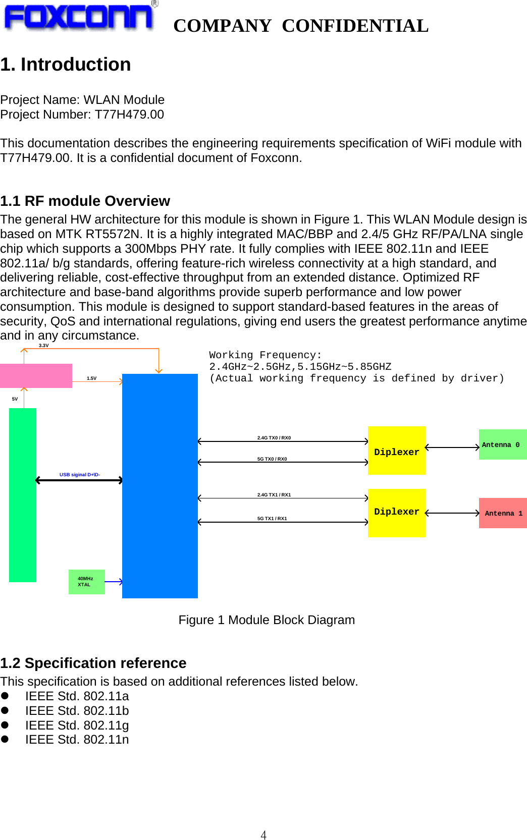
![COMPANY CONFIDENTIAL 5 1.3 System Functions Table1: General Specification as below: Main Chipset MTK RT5572N Operating Frequency[1] 2.412 GHz ~2.472GHz 5.180 GHz ~5.825 GHz WiFi Standard 802.11 a/b/g/n(2x2) Modulation 11b: DBPSK, DQPSK and CCK and DSSS 11g: BPSK, QPSK, 16QAM, 64QAM and OFDM 11n: MCS0~15 OFDM 11a: BPSK, QPSK, 16QAM, 64QAM and OFDM Data rates 11b:1, 2, 5.5 and 11Mbps 11g:6, 9, 12, 18, 24, 36, 48 and 54 Mbps 11n(2.4G&5G): MCS0~15, up to 300Mbps 11a:6,9,12,18,24,36,48,54Mbps Form factor 5pin side entry type WTB CONN, 1.25mm pitch, Host Interface USB 2.0 PCB Stack 4-layers design PCBA Dimension Typical,40mm(W)*46.45mm(L)*5.0mm(T) (The height including WTB connector and metal antennas) Antenna type Two metal antennas on-board Operation Temperature 0℃ to +60℃ Storage Temperature -40℃ to +85℃ Operation Voltage 5V +/-10% Sample picture as bellow[2] TOP view BOT view *[1] Actual operating frequency may differ base on country code setting (Read from driver setting) *[2] Above sample pictures are just for reference, may differ for different version 1 5](https://usermanual.wiki/CyberTAN-Technology/WU322HS/User-Guide-2126584-Page-5.png)
![COMPANY CONFIDENTIAL 6 2. Mechanical Specification 2.1 Mechanical Outline Drawing Typical PCBA Dimension (W x L x H): 40mmx46.45mmx5.00mm. Unit: mm 2.2 WTB CONNECTOR Pin definition 5pin, side entry type WTB CONN, 1.25mm pitch Pin No. of WTB connector is marked in sample picture(item 1.3) Pin # Name Description 1 VCC 5V DC power supply input 2 D- USB Data DP 3 D+ USB Data DN 4 GND GND 5 Ctrl WLAN ON/OFF[3] Pull low to disable WLAN card, internally pull high *[3] Module internally pull-high to 3.3V,no need for external pull-high](https://usermanual.wiki/CyberTAN-Technology/WU322HS/User-Guide-2126584-Page-6.png)
![COMPANY CONFIDENTIAL 7 3. Electrical Specification 3.1 802.11b Mode Items Contents Specification IEEE802.11b Mode DSSS / CCK Channel CH1 to CH13[4] Data rate 1, 2, 5.5, 11Mbps DC Characteristics Min. Typ. Max. Unit Remark 1.DC current (Average) 1) TX throughput mode 195 261 mA 2) RX throughput mode 151 274 mA TX Characteristics Min. Typ. Max. Unit 2. Power Levels(Calibrated) 1) 13dBm Target (For Each antenna port) 11 13 15 dBm 3. Spectrum Mask @ target power 1) fc +/-11MHz to +/-22MHz - - -30 dBr 2) fc > +/-22MHz - - -50 dBr 4. Frequency Error -25 -1 +25 ppm RX Characteristics(For single chain) Min. Typ. Max. Unit 5 Minimum Input Level Sensitivity 1) 1Mbps (FER≦8%) - -96 -83 dBm 2) 2Mbps (FER≦8%) - -92 -80 dBm 3) 5.5Mbps (FER≦8%) - -90 -79 dBm 4) 11Mbps (FER≦8%) - -88 -76 dBm 6 Maximum Input Level (FER≦8%) -10 - dBm *[4]Actual working channel may differ for different country(read from INF and registry),this description apply to 11a/g/n](https://usermanual.wiki/CyberTAN-Technology/WU322HS/User-Guide-2126584-Page-7.png)
![COMPANY CONFIDENTIAL 10 3.4 802.11n 2.4G HT40 Mode *[5]Actual working channel may differ for different country(read from INF and registry) Items Contents Specification IEEE802.11n HT40 @ 2.4GHz Mode OFDM Channel CH3 to CH11[5] Data rate (MCS index) MCS0/1/2/3/4/5/6/7/8/9/10/11/12/13/14/15 DC Characteristics Min. Typ. Max. Unit Remark 1.DC current(Average) 1) TX throughput mode 295 440 mA 2) RX throughput mode 187 445 mA TX Characteristics Min. Typ. Max. Unit 2. Power Levels (Calibrated) 1) 11dBm Target (For Each antenna port) 9 11 13 dBm 3. Spectrum Mask @ target power 1) at fc +/- 22MHz - - -20 dBr 2) at fc +/- 40MHz - - -28 dBr 3) at fc > +/-60MHz - - -45 dBr 4. Constellation Error(EVM)@target power 1) MCS0 - - -5 dB 2) MCS1 - - -10 dB 3) MCS2 - - -13 dB 4) MCS3 - - -16 dB 5) MCS4 - - -19 dB 6) MCS5 - - -22 dB 7) MCS6 - - -25 dB 8) MCS7 - -30 -28 dB 5. Frequency Error *1 -25 -1.3 +25 ppm RX Characteristics(For single chain) Min. Typ. Max. Unit 6. Minimum Input Level Sensitivity 1) MCS0 (PER ≤ 10%) - -87 -79 dBm 2) MCS1 (PER ≤ 10%) - -84 -76 dBm 3) MCS2 (PER ≤ 10%) - -82 -74 dBm 4) MCS3 (PER ≤ 10%) - -78 -71 dBm 5) MCS4 (PER ≤ 10%) - -75 -67 dBm 6) MCS5 (PER ≤ 10%) - -70 -63 dBm 7) MCS6 (PER ≤ 10%) - -69 -62 dBm 8) MCS7 (PER ≤ 10%) - -68 -61 dBm 7. Maximum Input Level (PER ≤ 10%) -20 dBm](https://usermanual.wiki/CyberTAN-Technology/WU322HS/User-Guide-2126584-Page-10.png)
![COMPANY CONFIDENTIAL 11 3.5 802.11a Mode *[6]Actual working channel may differ for different country(read from INF and registry) Items Contents Specification IEEE802.11a @ 5GHz Mode OFDM Channel Band1:5.18GHz~5.24GHz Band2:5.26GHz~5.32GH Band3:5.50GHz~5.68GHz Band4:5.745GHz~5.825GHz[6] Data rate (MCS index) 6, 9, 12, 18, 24, 36, 48, 54Mbps DC Characteristics Min. Typ. Max. Unit Remark 1.DC current(Average) 1) TX throughput mode 215 303 mA 2) RX throughput mode 176 317 mA TX Characteristics Min. Typ. Max. Unit 2. Power Levels 1) 12dBm Target (For Each antenna port) 10 12 14 dBm 3. Spectrum Mask @ target power 1) at fc +/- 11MHz - - -20 dBr 2) at fc +/- 20MHz - - -28 dBr 3) at fc > +/-30MHz - - -40 dBr 4 Constellation Error(EVM)@ target power 1) 6Mbps - - -5 dB 2) 9Mbps - - -8 dB 3) 12Mbps - - -10 dB 4) 18Mbps - - -13 dB 5) 24Mbps - - -16 dB 6) 36Mbps - - -19 dB 7) 48Mbps - - -22 dB 8) 54Mbps - -32 -25 dB 5 Frequency Error *1 -20 -1.1 +20 ppm RX Characteristics(For single chain) Min. Typ. Max. Unit 6 Minimum Input Level Sensitivity 1) 6Mbps (PER ≤ 10%) - -91 -82 dBm 2) 9Mbps (PER ≤ 10%) - -89 -81 dBm 3) 12Mbps (PER ≤ 10%) - -88 -79 dBm 4) 18Mbps (PER ≤ 10%) - -86 -77 dBm 5) 24Mbps (PER ≤ 10%) - -82 -74 dBm 6) 36Mbps (PER ≤ 10%) - -80 -70 dBm 7) 48Mbps (PER ≤ 10%) - -74 -66 dBm 8) 54Mbps (PER ≤ 10%) - -73 -65 dBm 7 Maximum Input Level (PER ≤ 10%) -20 - dBm](https://usermanual.wiki/CyberTAN-Technology/WU322HS/User-Guide-2126584-Page-11.png)

![COMPANY CONFIDENTIAL 14 4 Software Requirements The driver supports the following operating systems: Linux, Microsoft Windows XP and Win7. 5. Quality The product quality must be followed-up by Foxconn factory quality control system. 6. Appendix 6.1 Label information [7] *[7] Label information may be evolve as production revision evolve](https://usermanual.wiki/CyberTAN-Technology/WU322HS/User-Guide-2126584-Page-14.png)