CyberTAN Technology WU322HS WLAN Module User Manual 802
CyberTAN Technology Inc. WLAN Module 802
User Manual

COMPANY CONFIDENTIAL
1
IEEE 802.11 b/g/a/n 2T2R WLAN Module
(Project Name)
WLAN Module
(Foxconn Part No.)
T77H479.00
(Customer Part No.)
1130577
Foxconn reserves the right to make changes to any product or data herein to improve reliability,
function, design,or to pass regulations.Critical date or product changes will be presented in
newer version Revision Notes for customer.
Product Specification

COMPANY CONFIDENTIAL
2
Content
0. REVISION HISTORY
............................................................................ 3
1. INTRODUCTION
............................................................................... 4
1.1 RF MODULE OVERVIEW......................................................................... 4
1.2 SPECIFICATION REFERENCE ..................................................................... 4
1.3 SYSTEM FUNCTIONS ........................................................................... 5
2. MECHANICAL SPECIFICATION
................................................................. 6
2.1 MECHANICAL OUTLINE DRAWING ................................................................. 6
2.2 WTB CONNECTOR PIN DEFINITION ............................................................. 6
3. ELECTRICAL SPECIFICATION
.................................................................. 7
3.1 802.11B MODE ............................................................................... 7
3.2 802.11G MODE ............................................................................... 8
3.3 802.11N 2.4G HT20 MODE ..................................................................... 9
3.4 802.11N 2.4G HT40 MODE .................................................................... 10
3.5 802.11A MODE .............................................................................. 11
3.6 802.11N 5G HT20 MODE ...................................................................... 12
3.7 802.11N 5G HT40 MODE ...................................................................... 13
4 SOFTWARE REQUIREMENTS
.................................................................. 14
5. QUALITY
..................................................................................... 14
6. APPENDIX
................................................................................... 14
6.1 LABEL INFORMATION [6] ........................................................................ 14
6.2 PACKAGE INFORMATION ....................................................................... 15
6.3 FEDERAL COMMUNICATION COMMISSION INTERFERENCE STATEMENT .................................. 16

COMPANY CONFIDENTIAL
3
0. Revision History
Date Document
revision
Product
revision Change Description
2013/05/02 00 015 Initial release(preliminary)
2013/06/04 01 015
1. Add customer part number
2. Update label design
3. Remove i-pex connector
2013/07/14 02 015
1. Change 11b power from 16dBm to 13dBm for
each chain to pass CE and C-tick
2. Add power consumption
2013/08/10 03 025 1. Update label design
2013/9/25 04 025
1. Change 11n 2.4G band HT40 power from
13dBm to 11dBm to pass FCC band-edge
2. Update Label design(add FCC logo)
3. Update Block Diagram to module level
COMPANY CONFIDENTIAL
4
1. Introduction
Project Name: WLAN Module
Project Number: T77H479.00
This documentation describes the engineering requirements specification of WiFi module with
T77H479.00. It is a confidential document of Foxconn.
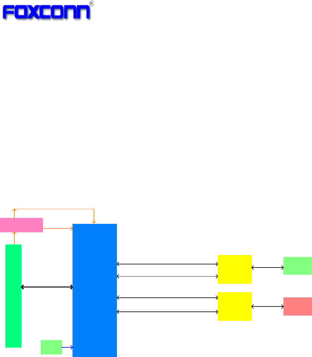
1.1 RF module Overview
The general HW architecture for this module is shown in Figure 1. This WLAN Module design is
based on MTK RT5572N. It is a highly integrated MAC/BBP and 2.4/5 GHz RF/PA/LNA single
chip which supports a 300Mbps PHY rate. It fully complies with IEEE 802.11n and IEEE
802.11a/ b/g standards, offering feature-rich wireless connectivity at a high standard, and
delivering reliable, cost-effective throughput from an extended distance. Optimized RF
architecture and base-band algorithms provide superb performance and low power
consumption. This module is designed to support standard-based features in the areas of
security, QoS and international regulations, giving end users the greatest performance anytime
and in any circumstance.
Figure 1 Module Block Diagram
1.2 Specification reference
This specification is based on additional references listed below.
IEEE Std. 802.11a
IEEE Std. 802.11b
IEEE Std. 802.11g
IEEE Std. 802.11n
Working Frequency:
2.4GHz~2.5GHz,5.15GHz~5.85GHZ
(Actual working frequency is defined by driver)
5V
3.3V
USB Interface
USB siginal D+\D-
5G TX1 / RX1
2.4G TX1 / RX1
2.4G TX0 / RX0
5G TX0 / RX0
1.5V
40MHz
XTAL
Antenna 1
Antenna 0
Diplexer
Diplexer
Switch Regulator
RT5572N
COMPANY CONFIDENTIAL
5
1.3 System Functions
Table1: General Specification as below:
Main Chipset
MTK RT5572N
Operating Frequency[1]
2.412 GHz ~2.472GHz
5.180 GHz ~5.825 GHz
WiFi Standard
802.11 a/b/g/n(2x2)
Modulation
11b: DBPSK, DQPSK and CCK and DSSS
11g: BPSK, QPSK, 16QAM, 64QAM and OFDM
11n: MCS0~15 OFDM
11a: BPSK, QPSK, 16QAM, 64QAM and OFDM
Data rates
11b:1, 2, 5.5 and 11Mbps
11g:6, 9, 12, 18, 24, 36, 48 and 54 Mbps
11n(2.4G&5G): MCS0~15, up to 300Mbps
11a:6,9,12,18,24,36,48,54Mbps
Form factor
5pin side entry type WTB CONN, 1.25mm pitch,
Host Interface
USB 2.0
PCB Stack
4-layers design
PCBA Dimension
Typical,40mm(W)*46.45mm(L)*5.0mm(T)
(The height including WTB connector and metal
antennas)
Antenna type
Two metal antennas on-board
Operation Temperature
0
℃
to +60
℃
Storage Temperature
-40
℃
to +85
℃
Operation Voltage
5V +/-10%
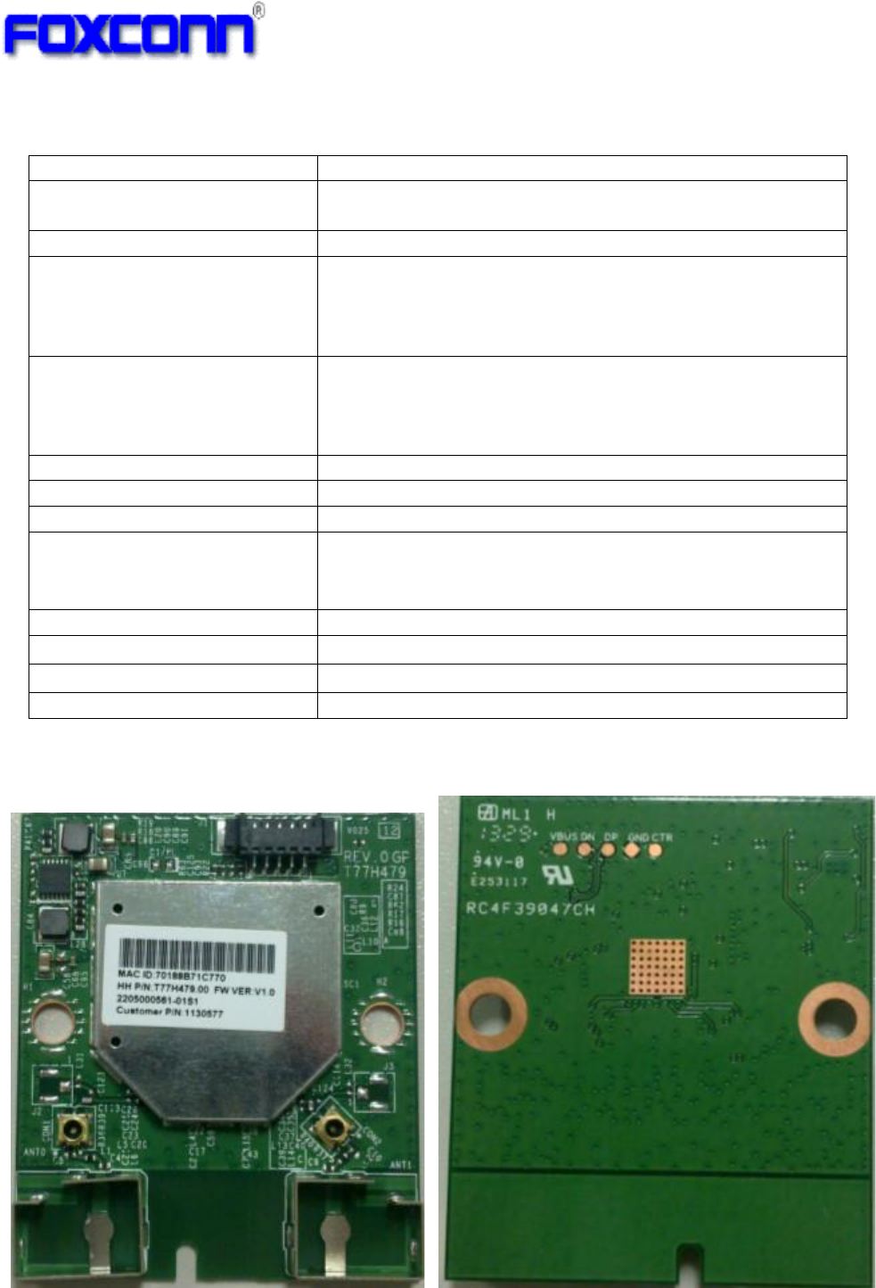
Sample picture as bellow[2]
TOP view BOT view
*[1] Actual operating frequency may differ base on country code setting (Read from driver setting)
*[2] Above sample pictures are just for reference, may differ for different version
1
5
COMPANY CONFIDENTIAL
6
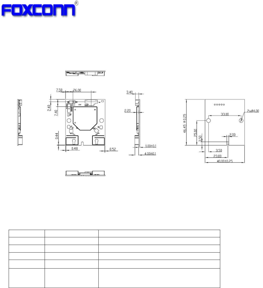
2. Mechanical Specification
2.1 Mechanical Outline Drawing
Typical PCBA Dimension (W x L x H): 40mmx46.45mmx5.00mm.
Unit: mm
2.2 WTB CONNECTOR Pin definition
5pin, side entry type WTB CONN, 1.25mm pitch
Pin No. of WTB connector is marked in sample picture(item 1.3)
Pin #
Name
Description
1
VCC
5V DC power supply input
2
D-
USB Data DP
3
D+
USB Data DN
4
GND
GND
5
Ctrl
WLAN ON/OFF[3]
Pull low to disable WLAN card, internally pull
high
*[3] Module internally pull-high to 3.3V,no need for external pull-high
COMPANY CONFIDENTIAL
7
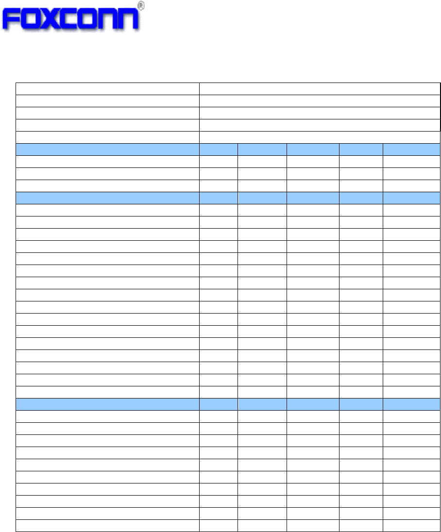
3. Electrical Specification
3.1 802.11b Mode
Items
Contents
Specification IEEE802.11b
Mode
DSSS / CCK
Channel CH1 to CH13
[4]
Data rate 1, 2, 5.5, 11Mbps
DC Characteristics Min. Typ. Max. Unit Remark
1.DC current (Average)
1) TX throughput mode 195 261 mA
2) RX throughput mode 151 274 mA
TX Characteristics
Min.
Typ.
Max.
Unit
2. Power Levels(Calibrated)
1) 13dBm Target (For Each antenna port)
11 13 15
dBm
3. Spectrum Mask @ target power
1) fc +/-11MHz to +/-22MHz
-
-
-30
dBr
2) fc > +/-22MHz - - -50 dBr
4. Frequency Error
-25
-1
+25
ppm
RX Characteristics(For single chain)
Min.
Typ.
Max.
Unit
5 Minimum Input Level Sensitivity
1) 1Mbps (FER≦8%) - -96 -83 dBm
2) 2Mbps (FER
≦
8%)
-
-92
-80
dBm
3) 5.5Mbps (FER
≦
8%)
-
-90
-79
dBm
4) 11Mbps (FER≦8%) - -88 -76 dBm
6 Maximum Input Level (FER≦8%) -10 - dBm
*[4]Actual working channel may differ for different country(read from INF and registry),this description
apply to 11a/g/n
COMPANY CONFIDENTIAL
8
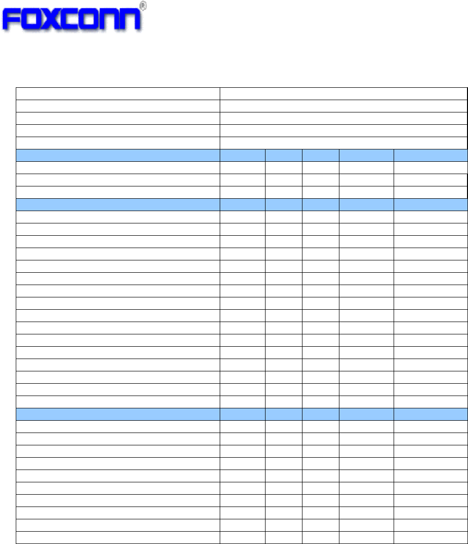
3.2 802.11g Mode
Items
Contents
Specification IEEE802.11g
Mode
OFDM
Channel CH1 to CH13
Data rate
6, 9, 12, 18, 24, 36, 48, 54Mbps
DC Characteristics
Min. Typ. Max. Unit Remark
1.DC current(Average)
1) TX throughput mode 191 286 mA
2) RX throughput mode
154
281
mA
TX Characteristics
Min. Typ. Max. Unit
2. Power Levels
1) 14dBm Target (For Each antenna port) 12 14 16 dBm
3. Spectrum Mask @ target power
1) at fc +/- 11MHz - - -20 dBr
2) at fc +/- 20MHz
-
-
-28
dBr
3) at fc > +/-30MHz - - -40 dBr
4 Constellation Error(EVM)@ target power
1) 6Mbps - - -5 dB
2) 9Mbps
-
-
-8
dB
3) 12Mbps - - -10 dB
4) 18Mbps
-
-
-13
dB
5) 24Mbps - - -16 dB
6) 36Mbps
-
-
-19
dB
7) 48Mbps - - -22 dB
8) 54Mbps
-
-32
-25
dB
5 Frequency Error *
1
-25 -1.1 +25 ppm
RX Characteristics(For single chain)
Min.
Typ.
Max.
Unit
6 Minimum Input Level Sensitivity
1) 6Mbps (PER ≤ 10%)
-
-91
-85
dBm
2) 9Mbps (PER ≤ 10%) -
-89
-84 dBm
3) 12Mbps (PER ≤ 10%)
-
-89
-82
dBm
4) 18Mbps (PER ≤ 10%) -
-86
-80 dBm
5) 24Mbps (PER ≤ 10%)
-
-84
-77
dBm
6) 36Mbps (PER ≤ 10%) -
-80
-73 dBm
7) 48Mbps (PER ≤ 10%)
-
-75
-69
dBm
8) 54Mbps (PER ≤ 10%) - -74 -68 dBm
7 Maximum Input Level (PER ≤ 10%)
-20
-
dBm
COMPANY CONFIDENTIAL
9
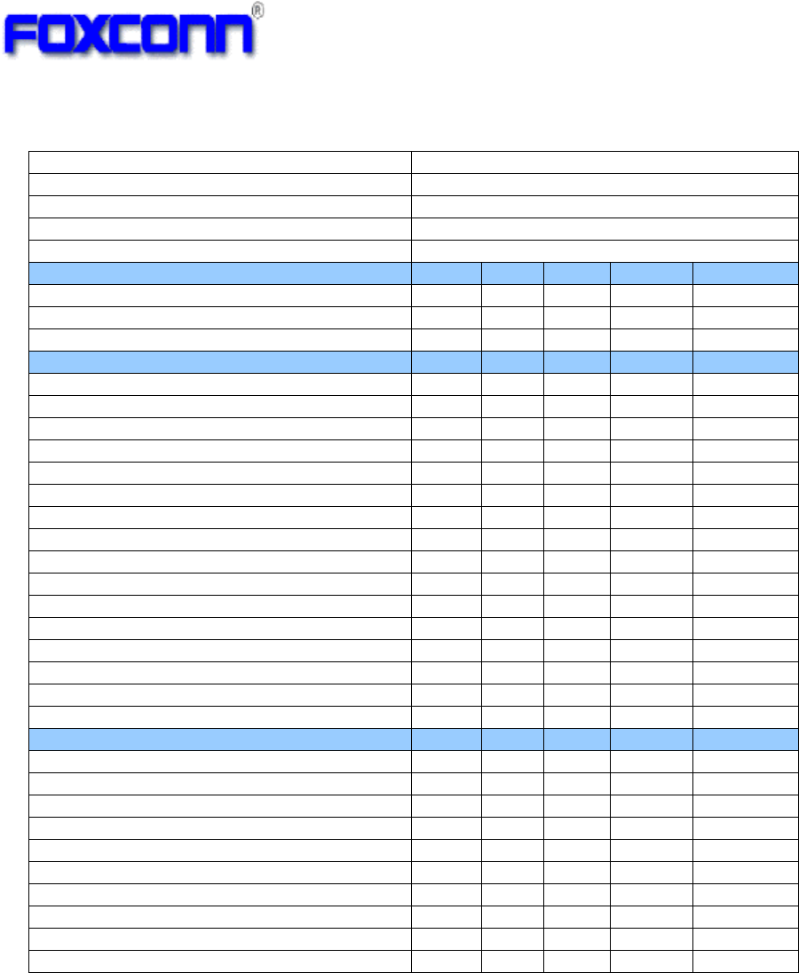
3.3 802.11n 2.4G HT20 Mode
Items
Contents
Specification
IEEE802.11n HT20 @ 2.4GHz
Mode
OFDM
Channel
CH1 to CH13
Data rate (MCS index) MCS0/1/2/3/4/5/6/7/8/9/10/11/12/13/14/15
DC Characteristics
Min.
Typ.
Max.
Unit
Remark
1.DC current(Average)
1) TX throughput mode
328
436
mA
2) RX throughput mode 172 436 mA
TX Characteristics
Min.
Typ.
Max.
Unit
2. Power Levels
14dBm Target (For Each antenna port)
12
14
16
dBm
3. Spectrum Mask @ target power
1) at fc +/- 11MHz
-
-
-20
dBr
2) at fc +/- 20MHz
-
-
-28
dBr
3) at fc > +/-30MHz
-
-
-45
dBr
4. Constellation Error(EVM)@ target power
1) MCS0
-
-
-5
dB
2) MCS1
-
-
-10
dB
3) MCS2
-
-
-13
dB
4) MCS3
-
-
-16
dB
5) MCS4
-
-
-19
dB
6) MCS5
-
-
-22
dB
7) MCS6
-
-
-25
dB
8) MCS7
-
-31
-28
dB
5. Frequency Error *1
-25
-1.2
+25
ppm
RX Characteristics(For single chain)
Min.
Typ.
Max.
Unit
6. Minimum Input Level Sensitivity
1) MCS0 (PER ≤ 10%)
-
-90
-82
dBm
2) MCS1 (PER ≤ 10%)
-
-88
-79
dBm
3) MCS2 (PER ≤ 10%)
-
-86
-77
dBm
4) MCS3 (PER ≤ 10%)
-
-83
-74
dBm
5) MCS4 (PER ≤ 10%)
-
-79
-70
dBm
6) MCS5 (PER ≤ 10%)
-
-74
-66
dBm
7) MCS6 (PER ≤ 10%)
-
-73
-65
dBm
8) MCS7 (PER ≤ 10%)
-
-71
-64
dBm
7. Maximum Input Level (PER ≤ 10%)
-20
-
dBm
COMPANY CONFIDENTIAL
10
3.4 802.11n 2.4G HT40 Mode
*[5]Actual working channel may differ for different country(read from INF and registry)
Items
Contents
Specification
IEEE802.11n HT40 @ 2.4GHz
Mode
OFDM
Channel
CH3 to CH11[5]
Data rate (MCS index)
MCS0/1/2/3/4/5/6/7/8/9/10/11/12/13/14/15
DC Characteristics
Min. Typ. Max. Unit Remark
1.DC current(Average)
1) TX throughput mode 295 440 mA
2) RX throughput mode
187
445
mA
TX Characteristics
Min.
Typ.
Max.
Unit
2. Power Levels (Calibrated)
1) 11dBm Target (For Each antenna port)
9 11 13
dBm
3. Spectrum Mask @ target power
1) at fc +/- 22MHz
-
-
-20
dBr
2) at fc +/- 40MHz
-
-
-28
dBr
3) at fc > +/-60MHz
-
-
-45
dBr
4. Constellation Error(EVM)@target power
1) MCS0
-
-
-5
dB
2) MCS1
-
-
-10
dB
3) MCS2
-
-
-13
dB
4) MCS3
-
-
-16
dB
5) MCS4
-
-
-19
dB
6) MCS5
-
-
-22
dB
7) MCS6
-
-
-25
dB
8) MCS7
-
-30
-28
dB
5. Frequency Error *1
-25
-1.3
+25
ppm
RX Characteristics(For single chain)
Min.
Typ.
Max.
Unit
6. Minimum Input Level Sensitivity
1) MCS0 (PER ≤ 10%)
-
-87
-79
dBm
2) MCS1 (PER ≤ 10%)
-
-84
-76
dBm
3) MCS2 (PER ≤ 10%)
-
-82
-74
dBm
4) MCS3 (PER ≤ 10%)
-
-78
-71
dBm
5) MCS4 (PER ≤ 10%)
-
-75
-67
dBm
6) MCS5 (PER ≤ 10%)
-
-70
-63
dBm
7) MCS6 (PER ≤ 10%)
-
-69
-62
dBm
8) MCS7 (PER ≤ 10%)
-
-68 -61
dBm
7. Maximum Input Level (PER ≤ 10%)
-20
dBm

COMPANY CONFIDENTIAL
11
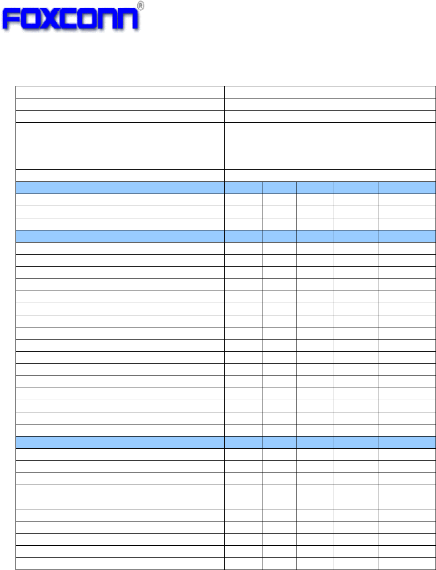
3.5 802.11a Mode
*[6]Actual working channel may differ for different country(read from INF and registry)
Items
Contents
Specification
IEEE802.11a @ 5GHz
Mode
OFDM
Channel
Band1:5.18GHz~5.24GHz
Band2:5.26GHz~5.32GH
Band3:5.50GHz~5.68GHz
Band4:5.745GHz
~
5.825GHz
[6]
Data rate (MCS index) 6, 9, 12, 18, 24, 36, 48, 54Mbps
DC Characteristics
Min.
Typ.
Max.
Unit
Remark
1.DC current(Average)
1) TX throughput mode
215
303
mA
2) RX throughput mode 176 317 mA
TX Characteristics
Min.
Typ.
Max.
Unit
2. Power Levels
1) 12dBm Target (For Each antenna port)
10
12
14
dBm
3. Spectrum Mask @ target power
1) at fc +/- 11MHz
-
-
-20
dBr
2) at fc +/- 20MHz - - -28 dBr
3) at fc > +/-30MHz
-
-
-40
dBr
4 Constellation Error(EVM)@ target power
1) 6Mbps
-
-
-5
dB
2) 9Mbps - - -8 dB
3) 12Mbps
-
-
-10
dB
4) 18Mbps - - -13 dB
5) 24Mbps
-
-
-16
dB
6) 36Mbps - - -19 dB
7) 48Mbps
-
-
-22
dB
8) 54Mbps - -32 -25 dB
5 Frequency Error *1
-20
-1.1
+20
ppm
RX Characteristics(For single chain)
Min. Typ. Max. Unit
6 Minimum Input Level Sensitivity
1) 6Mbps (PER ≤ 10%) -
-91
-82 dBm
2) 9Mbps (PER ≤ 10%)
-
-89
-81
dBm
3) 12Mbps (PER ≤ 10%) -
-88
-79 dBm
4) 18Mbps (PER ≤ 10%)
-
-86
-77
dBm
5) 24Mbps (PER ≤ 10%) -
-82
-74 dBm
6) 36Mbps (PER ≤ 10%)
-
-80
-70
dBm
7) 48Mbps (PER ≤ 10%) -
-74
-66 dBm
8) 54Mbps (PER ≤ 10%)
-
-73
-65
dBm
7 Maximum Input Level (PER ≤ 10%) -20 - dBm
COMPANY CONFIDENTIAL
12
3.6 802.11n 5G HT20 Mode
Items
Contents
Specification
IEEE802.11n HT20 @ 5GHz
Mode
OFDM
Channel
Band1:5.18GHz~5.24GHz
Band2:5.26GHz~5.32GH
Band3:5.50GHz~5.68GHz
Band4:5.745GHz
~
5.825GHz
Data rate (MCS index) MCS0/1/2/3/4/5/6/7/8/9/10/11/12/13/14/15
DC Characteristics
Min.
Typ.
Max.
Unit
Remark
1.DC current(Average)
3) TX throughput mode
364
462
mA
4) RX throughput mode 172 462 mA
TX Characteristics
Min.
Typ.
Max.
Unit
2. Power Levels (Calibrated)
1) 12dBm Target (For Each antenna port)
10
12
14
dBm
3. Spectrum Mask @ target power
1) at fc +/- 22MHz
-
-
-20
dBr
2) at fc +/- 40MHz
-
-
-28
dBr
3) at fc > +/-60MHz
-
-
-45
dBr
4. Constellation Error(EVM)@target power
1) MCS0
-
-
-5
dB
2) MCS1
-
-
-10
dB
3) MCS2
-
-
-13
dB
4) MCS3
-
-
-16
dB
5) MCS4
-
-
-19
dB
6) MCS5
-
-
-22
dB
7) MCS6
-
-
-25
dB
8) MCS7
-
-30
-28
dB
5. Frequency Error *1
-20
-1.3
+20
ppm
RX Characteristics(For single chain)
Min.
Typ.
Max.
Unit
6. Minimum Input Level Sensitivity
1) MCS0 (PER ≤ 10%)
-
-89
-82
dBm
2) MCS1 (PER ≤ 10%)
-
-86
-79
dBm
3) MCS2 (PER ≤ 10%)
-
-85
-77
dBm
4) MCS3 (PER ≤ 10%)
-
-82
-74
dBm
5) MCS4 (PER ≤ 10%)
-
-78
-70
dBm
6) MCS5 (PER ≤ 10%)
-
-73
-66
dBm
7) MCS6 (PER ≤ 10%)
-
-72
-65
dBm
8) MCS7 (PER ≤ 10%)
-
-70
-64
dBm
7. Maximum Input Level (PER ≤ 10%)
-20
dBm

COMPANY CONFIDENTIAL
13
3.7 802.11n 5G HT40 Mode
Items
Contents
Specification
IEEE802.11n HT40 @ 5GHz
Mode
OFDM
Channel
Band1:5.18GHz~5.24GHz
Band2:5.26GHz~5.32GH
Band3:5.50GHz~5.68GHz
Band4:5.745GHz
~
5.825GHz
Data rate (MCS index) MCS0/1/2/3/4/5/6/7/8/9/10/11/12/13/14/15
DC Characteristics
Min.
Typ.
Max.
Unit
Remark
1.DC current(Average)
3) TX throughput mode
331
476
mA
4) RX throughput mode 207 476 mA
TX Characteristics
Min.
Typ.
Max.
Unit
2. Power Levels (Calibrated)
1) 11dBm Target (For Each antenna port)
9
11
13
dBm
3. Spectrum Mask @ target power
1) at fc +/- 22MHz
-
-
-20
dBr
2) at fc +/- 40MHz
-
-
-28
dBr
3) at fc > +/-60MHz
-
-
-45
dBr
4. Constellation Error(EVM)@target power
1) MCS0
-
-
-5
dB
2) MCS1
-
-
-10
dB
3) MCS2
-
-
-13
dB
4) MCS3
-
-
-16
dB
5) MCS4
-
-
-19
dB
6) MCS5
-
-
-22
dB
7) MCS6
-
-
-25
dB
8) MCS7
-
-30
-28
dB
5. Frequency Error *1
-20
-1.3
+20
ppm
RX Characteristics(For single chain)
Min.
Typ.
Max.
Unit
6. Minimum Input Level Sensitivity
1) MCS0 (PER ≤ 10%)
-
-86
-79
dBm
2) MCS1 (PER ≤ 10%)
-
-83
-76
dBm
3) MCS2 (PER ≤ 10%)
-
-81
-74
dBm
4) MCS3 (PER ≤ 10%)
-
-78
-71
dBm
5) MCS4 (PER ≤ 10%)
-
-75
-67
dBm
6) MCS5 (PER ≤ 10%)
-
-70
-63
dBm
7) MCS6 (PER ≤ 10%)
-
-69
-62
dBm
8) MCS7 (PER ≤ 10%)
-
-67
-61
dBm
7. Maximum Input Level (PER ≤ 10%)
-20
dBm
COMPANY CONFIDENTIAL
14
4 Software Requirements
The driver supports the following operating systems: Linux, Microsoft Windows XP and Win7.
5. Quality
The product quality must be followed-up by Foxconn factory quality control system.
6. Appendix
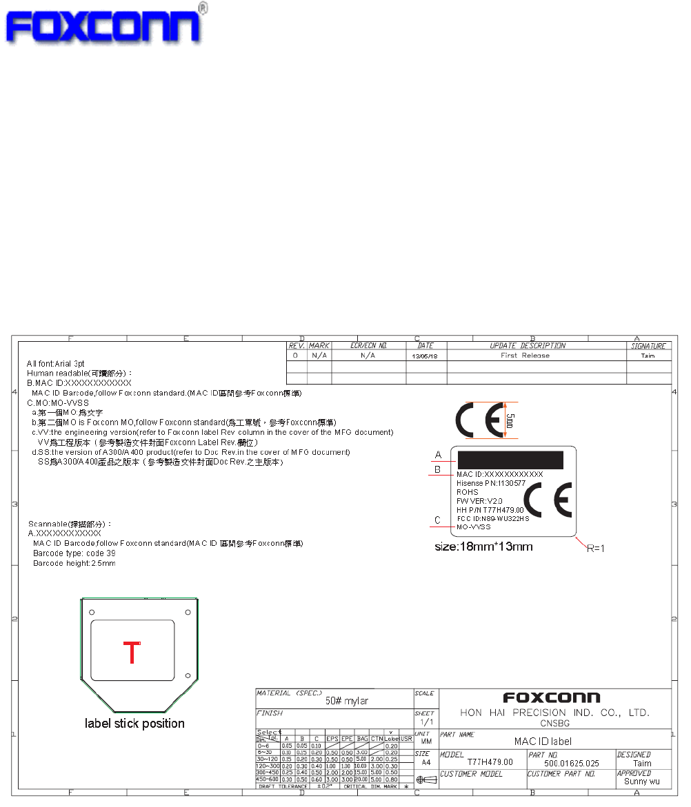
6.1 Label information [7]
*[7] Label information may be evolve as production revision evolve
COMPANY CONFIDENTIAL
15
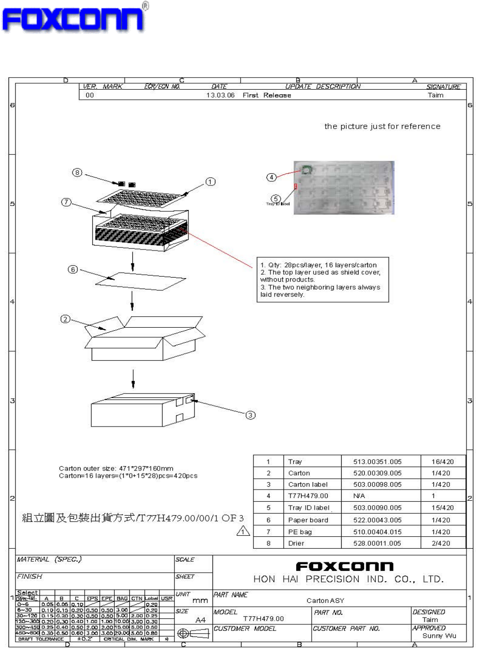
6.2 Package information

COMPANY CONFIDENTIAL
16
6.3 Federal Communication Commission Interference Statement
This equipment has been tested and found to comply with the limits for a Class B digital device,
pursuant to Part 15 of the FCC Rules. These limits are designed to provide reasonable
protection against harmful interference in a residential installation. This equipment generates,
uses and can radiate radio frequency energy and, if not installed and used in accordance with
the instructions, may cause harmful interference to radio communications. However, there is
no guarantee that interference will not occur in a particular installation. If this equipment does
cause harmful interference to radio or television reception, which can be determined by turning
the equipment off and on, the user is encouraged to try to correct the interference by one of the
following measures:
- Reorient or relocate the receiving antenna.
- Increase the separation between the equipment and receiver.
- Connect the equipment into an outlet on a circuit different from that to which the receiver is
connected.
- Consult the dealer or an experienced radio/TV technician for help.
FCC Caution:
Any changes or modifications not expressly approved by the party responsible for compliance
could void the user's authority to operate this equipment.
This device complies with Part 15 of the FCC Rules. Operation is subject to the following two
conditions:
(1) This device may not cause harmful interference, and
(2) This device must accept any interference received, including interference that may cause
undesired operation.
FCC Radiation Exposure Statement:
This equipment complies with FCC radiation exposure limits set forth for an uncontrolled
environment. This transmitter module must not be co-located or operating in conjunction with
any other antenna or transmitter.
This End equipment should be installed and operated with a minimum distance of 20
centimeters between the radiator and your body.
IMPORTANT NOTE:
In the event that these conditions can not be met (for example certain laptop configurations or
co-location with another transmitter), then the FCC authorization is no longer considered valid
and the FCC ID can not be used on the final product. In these circumstances, the OEM
integrator will be responsible for re-evaluating the end product (including the transmitter) and
obtaining a separate FCC authorization.
End Product Labeling
The final end product must be labeled in a visible area with the following:
“Contains FCC ID: N89-BU067HS ”.
Manual Information to the End User
The OEM integrator has to be aware not to provide information to the end user regarding how
to install or remove this RF module in the user’s manual of the end product which integrates
this module.
Antennas
Only use the supplied antenna. Unauthorized antennas, modifications or change to the
antennas could violate FCC regulations and void the user’s authority to operate the equipment.
Caution:

COMPANY CONFIDENTIAL
17
For operation within 5.15 ~5.25GHz /5.25 ~5.35GHz/5.47 ~5.725GHz frequency range, it is
restricted to indoor operations to reduce any potential for harmful interference to co-channel
Mobile Satellite System (MSS) operations. The band from 5600-5650MHz will be disabled by
the software during the manufacturing and cannot be changed by the end user. This device
meets all the other requirements specified in Part 15E, Section 15.407 of the FCC Rules.
The availability of some specific channels and/or operational frequency bands are country
dependent and are firmware programmed at the factory to match the intended destination. The
firmware setting is not accessible by the end user.