Cypress Semiconductor 2001 EZ-BLE PRoC Module User Manual Manual
Cypress Semiconductor EZ-BLE PRoC Module Manual
UserManual.wiki
>
Cypress Semiconductor
>
2001 User Manual
Manual
Navigation menu
Upload a User Manual
Namespaces
Wiki Guide
HTML
PDF
Info
Views
User Manual
Discussion / Help
Navigation


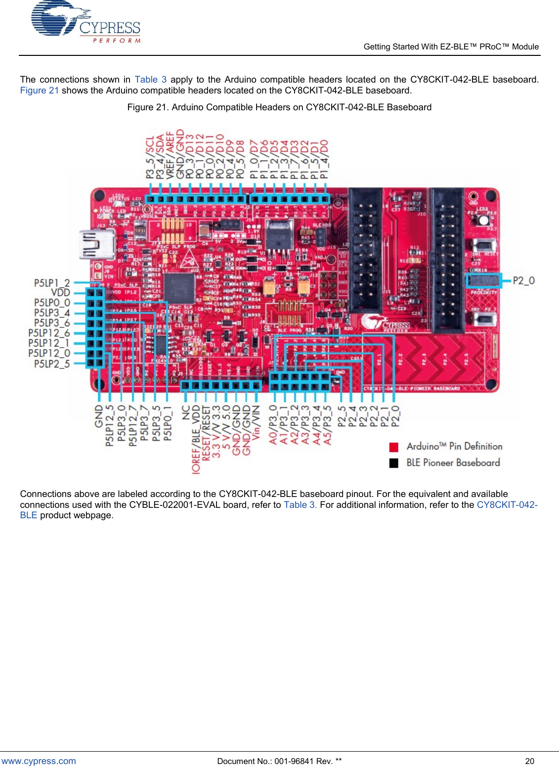
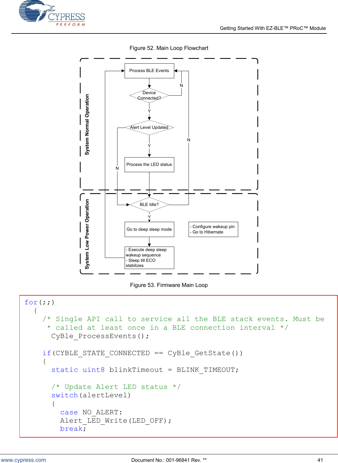
![Getting Started With EZ- Module www.cypress.com Document No.: 001-96841 Rev. ** 5 The connection pad spacing is listed in Table 1. Table 1. EZ-BLE PRoC Module Connection Pad Spacing (Center-to-Center) Pad X Pad Y Pad Pitch (Pad X - Pad Y) Comments Bottom-Left Corner 1 1.64 mm Distance from bottom left corner to Pad 1 center 1 2 0.76 mm Distance from Pad 1 center to Pad 2 center 2 3 0.76 mm Distance from Pad 2 center to Pad 3 center 3 4 0.76 mm Distance from Pad 3 center to Pad 4 center 4 5 0.76 mm Distance from Pad 4 center to Pad 5 center Top-Left Corner 6 0.81 mm Distance from top left corner to Pad 6 center 6 7 0.76 mm Distance from Pad 6 center to Pad 7 center 7 8 0.76 mm Distance from Pad 7 center to Pad 8 center 8 9 0.76 mm Distance from Pad 8 center to Pad 9 center 9 10 0.76 mm Distance from Pad 9 center to Pad 10 center 10 11 0.76 mm Distance from Pad 10 center to Pad 11 center 11 12 0.76 mm Distance from Pad 11 center to Pad 12 center 12 13 0.76 mm Distance from Pad 12 center to Pad 13 center 13 14 0.76 mm Distance from Pad 13 center to Pad 14 center 14 15 0.76 mm Distance from Pad 14 center to Pad 15 center 15 16 0.76 mm Distance from Pad 15 center to Pad 16 center 16 17 0.76 mm Distance from Pad 16 center to Pad 17 center Top-Right Corner 18 1.50 mm Distance from top right corner to Pad 18 center 18 19 0.76 mm Distance from Pad 18 center to Pad 19 center 19 20 0.76 mm Distance from Pad 19 center to Pad 20 center 20 21 0.76 mm Distance from Pad 20 center to Pad 21 center A list of the available I/Os and supported functionality for each I/O is shown in Table 2. Table 2. EZ-BLE PRoC Module Available Connections and Functionality Module Solder Pad Number Silicon Port Pin Functionality UART SPI I2C TCPWM CapSense WCO Out EXT_CLK/ ECO_OUT EXTPA_EN SWD GPIO 1 GND Ground Connection 2 P4[1] CTS MISO Yes Sensor/CTANK Yes 3 P5[1] TX SCLK SCL Yes Sensor Yes Yes 4 P5[0] RX SS SDA Yes Sensor Yes Yes 5 VDDR Radio Power Supply 1.9V to 5.5V](https://usermanual.wiki/Cypress-Semiconductor/2001/User-Guide-2607234-Page-5.png)
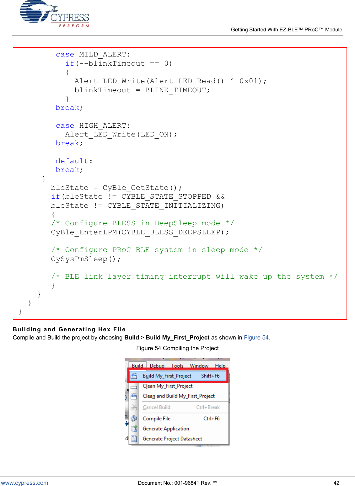
![Getting Started With EZ- Module www.cypress.com Document No.: 001-96841 Rev. ** 6 Module Solder Pad Number Silicon Port Pin Functionality UART SPI I2C TCPWM CapSense WCO Out EXT_CLK/ ECO_OUT EXTPA_EN SWD GPIO 6 P1[6] RTS SS Yes Sensor Yes 7 P0[7] CTS SCLK Yes Sensor SWDCLK1 Yes 8 P0[4] RX MOSI SDA Yes Sensor Yes Yes 9 P0[5] TX MISO SCL Yes Sensor Yes 10 GND Ground Connection 11 P0[6] RTS SS Yes Sensor SWDIO1 Yes 12 P1[7] CTS SCLK Yes Sensor Yes 13 VDD Digital Power Supply Input 1.71 to 5.5V 14 XRES External Reset Hardware Connection Input 15 P3[5] TX SCL Yes Sensor Yes 16 P3[4] RX SDA Yes Sensor Yes 17 P3[7] CTS MISO Yes Sensor Yes Yes 18 P1[4] RX MOSI SDA Yes Yes 19 P1[5] TX MISO SCL Yes Yes 20 P3[6] RTS Yes Sensor Yes 21 P4[0] RTS MOSI Yes CMOD Yes Low Pow e r M ode s EZ-BLE PRoC Module supports the following five power modes as illustrated in Figure 4: Active mode: This is the primary mode of operation. In this mode, all peripherals are available. Sleep mode: In this mode, the CPU is in sleep mode, SRAM is in retention, and all the peripherals are available. Any interrupt wakes up the CPU and returns the system to Active mode. Deep-Sleep mode: In this mode, the high-frequency clock (IMO) and all high-speed peripherals are off. The WDT, LCD, I2C/SPI, link layer, and low-frequency clock (32-kHz ILO) are available. Interrupts from GPIO, WDT, or SCBs can cause a wakeup. The current consumption in this mode is 1.3 µA for all PRoC BLE devices in the family. Hibernate mode: This power mode provides a best-in-class current consumption of 150 nA while retaining SRAM, programmable logic, and the ability to wake up from an interrupt generated by a GPIO. Stop mode: This power mode retains the GPIO states. Wakeup is possible by using the external reset (XRES) pin on the module. The current consumption in this mode is only 60 nA. 1 SDWCLK and SWDIO connections can be multiplexed as the functional options listed in each of the respective rows and can be used for programming without the need to reconfigure the device I/O.](https://usermanual.wiki/Cypress-Semiconductor/2001/User-Guide-2607234-Page-6.png)


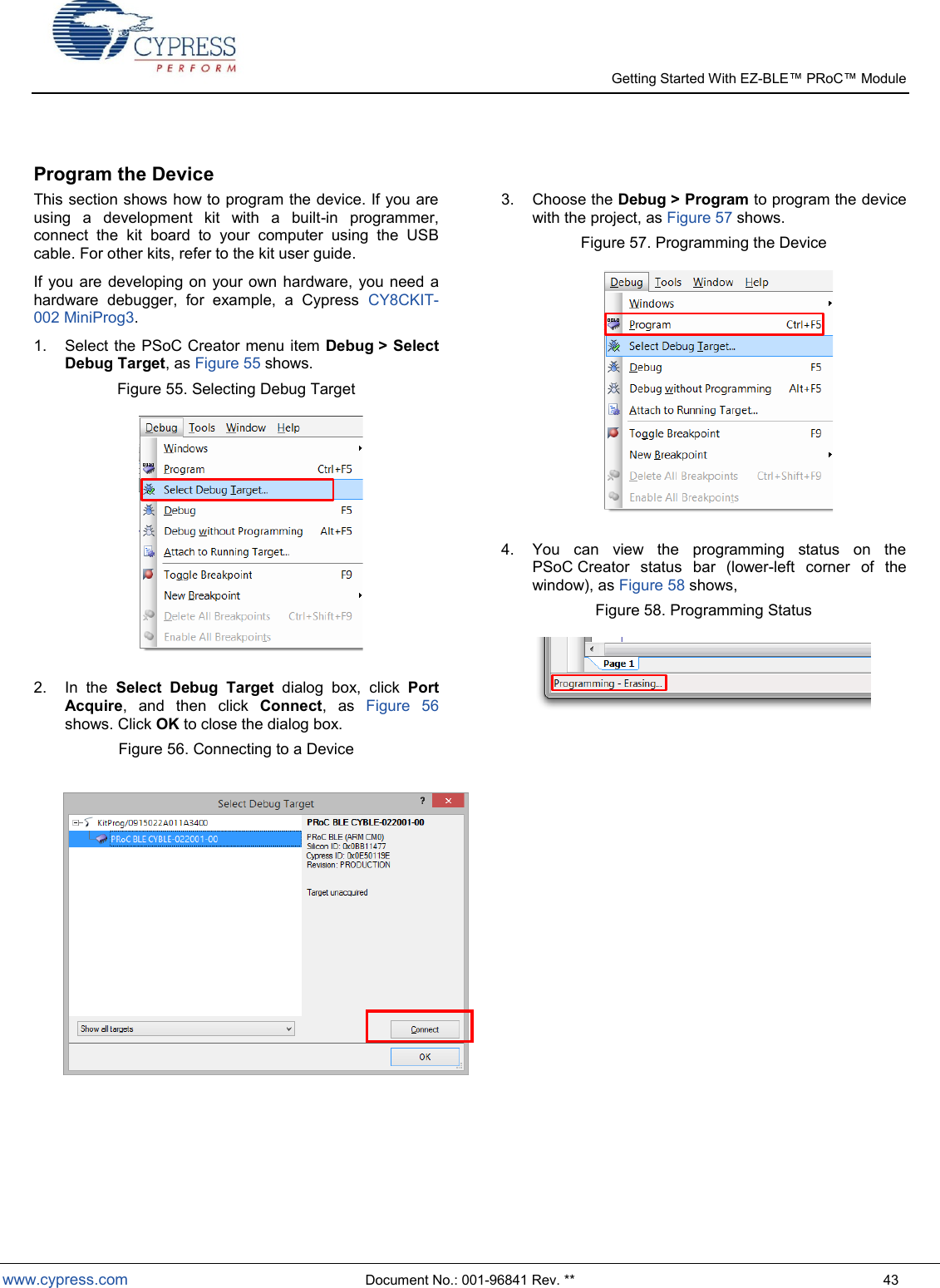
![Getting Started With EZ- www.cypress.com Document No.: 001-96841 Rev. ** 17 CYB LE -022001- E V AL C o n ne c ti on s to C Y 8 C KI T -042- B L E The CYBLE-022001-00 module contains 21 connections on the back side of the module. Each of these connections is present on the CYBLE-022001-EVAL evaluation board too. Figure 18 shows the CYBLE-022001-EVAL and highlights the elements on the top side of the board. Figure 18. CYBLE-022001-EVAL Board Top Side The CYBLE-022001-EVAL also includes the following elements: Cmod: A 2.2-nF capacitor mounted on the evaluation board used with the CY8CKIT-042-BLE capacitive sensing slider, buttons and proximity sensors. J3 Header: A two-pin header that exposes VDD and VDDR. J4 Header: A five-pin header that exposes connections used for programming the EZ-BLE PRoC Module Evaluation board by using the MiniProg3 kit, as shown in Figure 19. Figure 19. CYBLE-022001-EVAL Using CY8CKIT-002 MiniProg3 J5: A header that exposes P5[0] and P5[1], which can be used for I2C communication (including high speed I2C) to the EZ-BLE PRoC Module. J5 Header](https://usermanual.wiki/Cypress-Semiconductor/2001/User-Guide-2607234-Page-17.png)


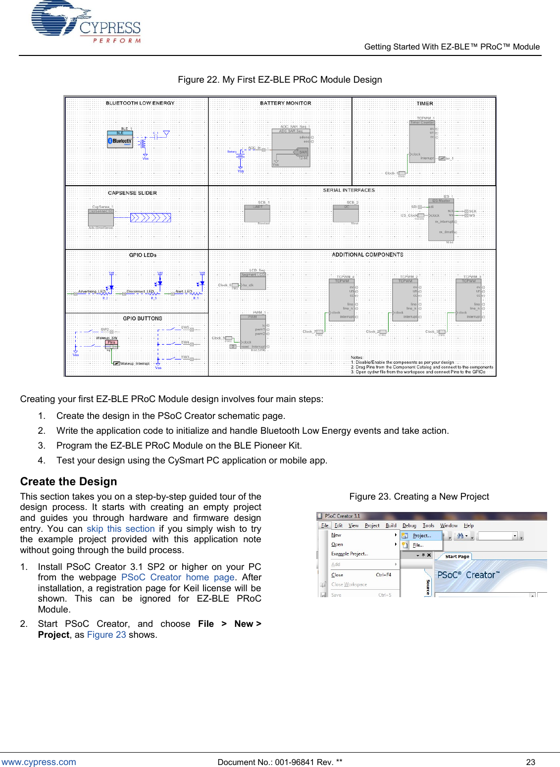
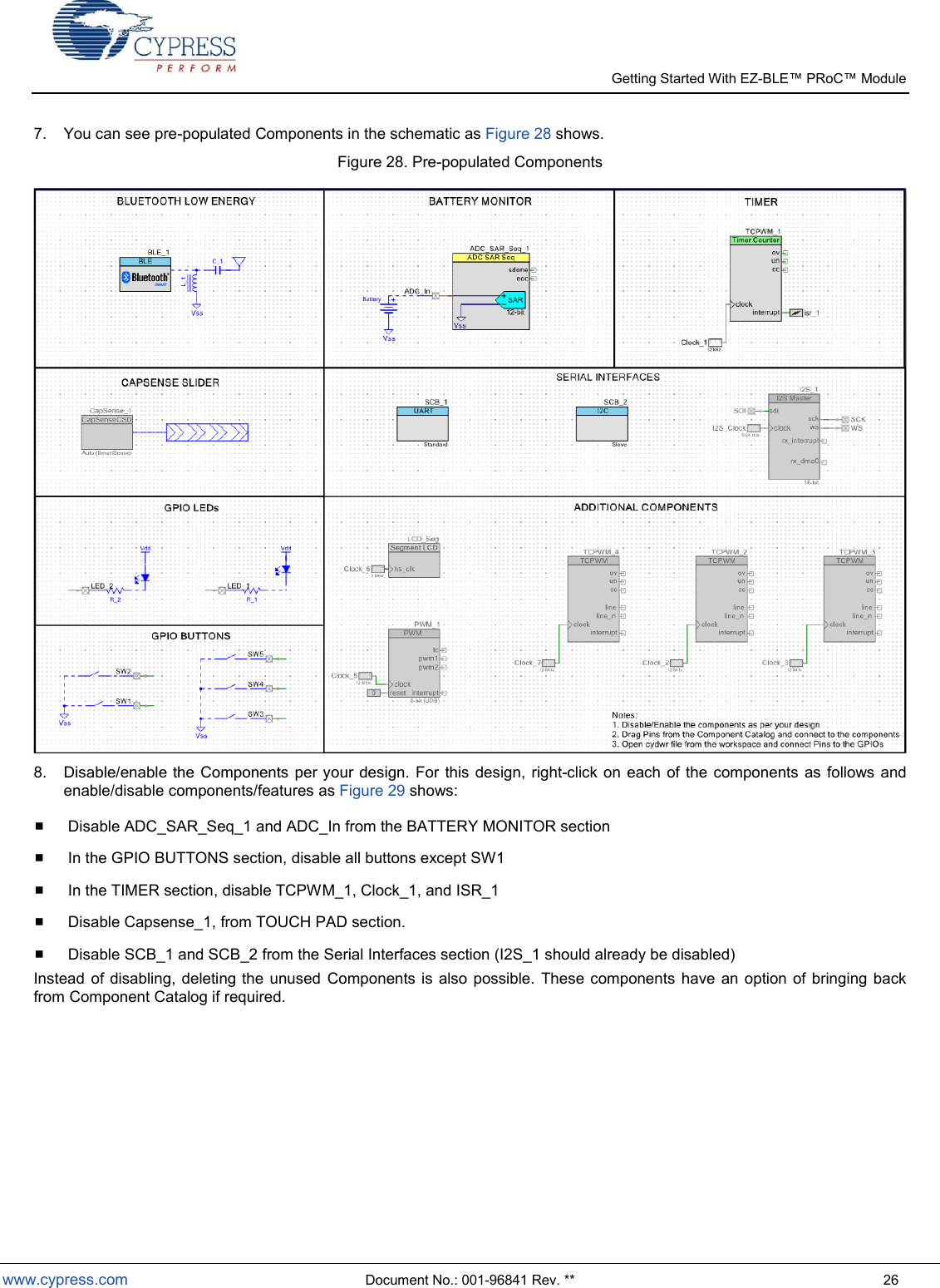
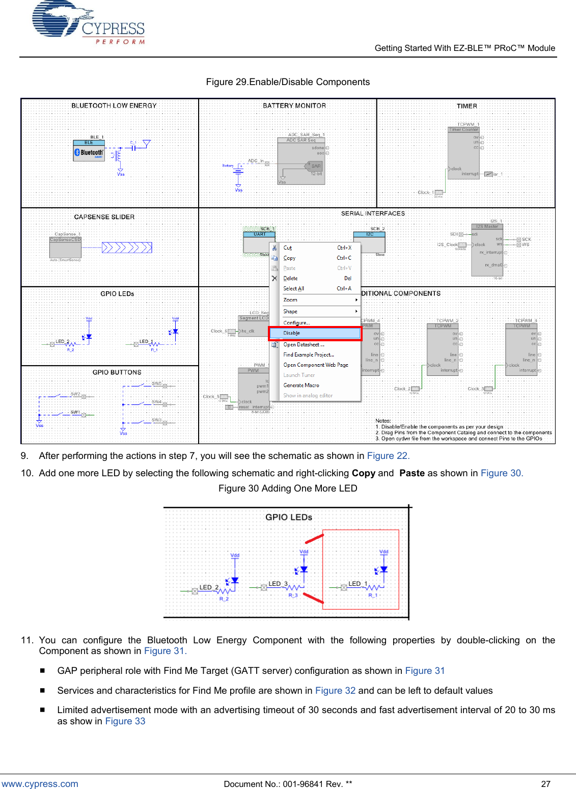
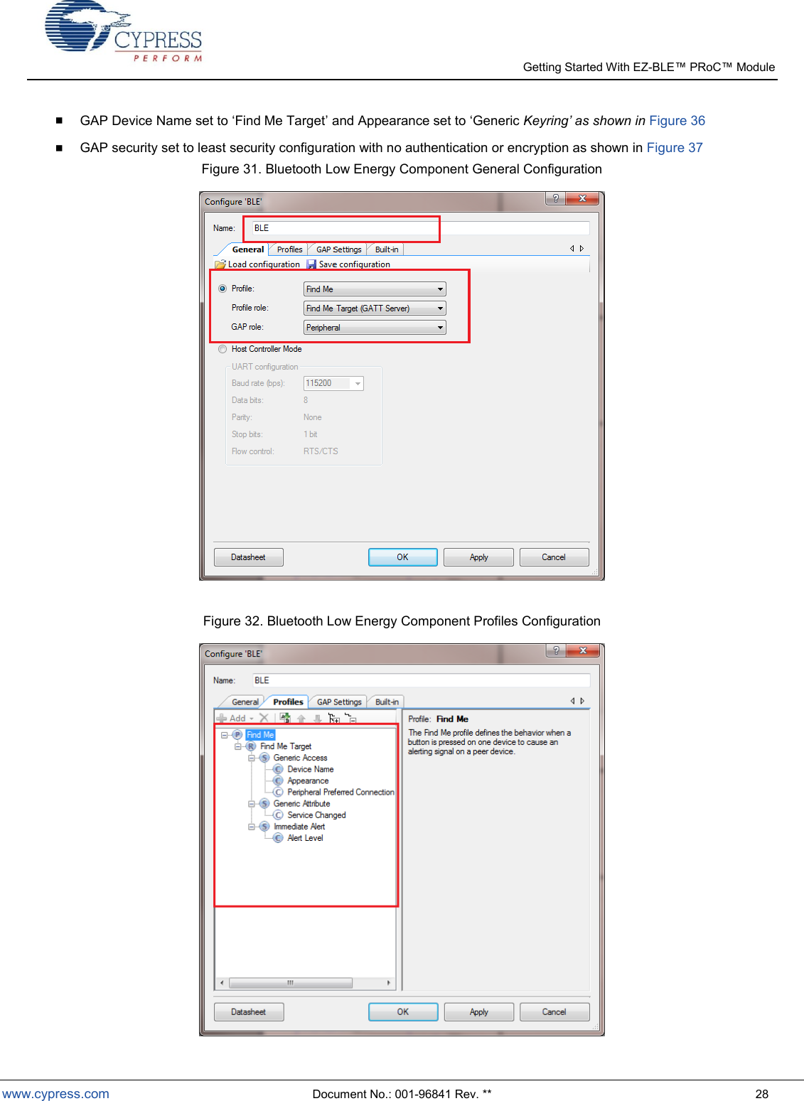


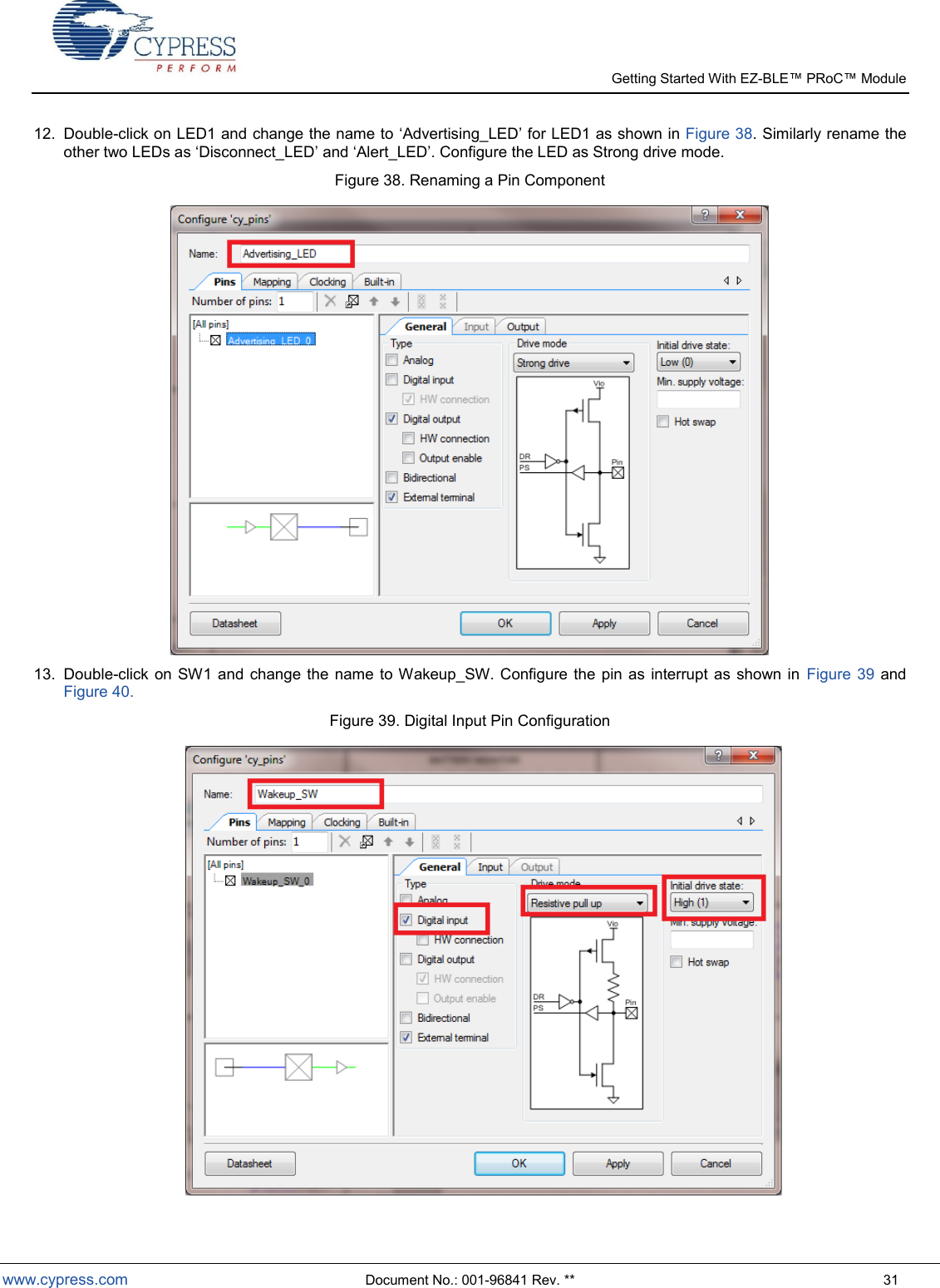
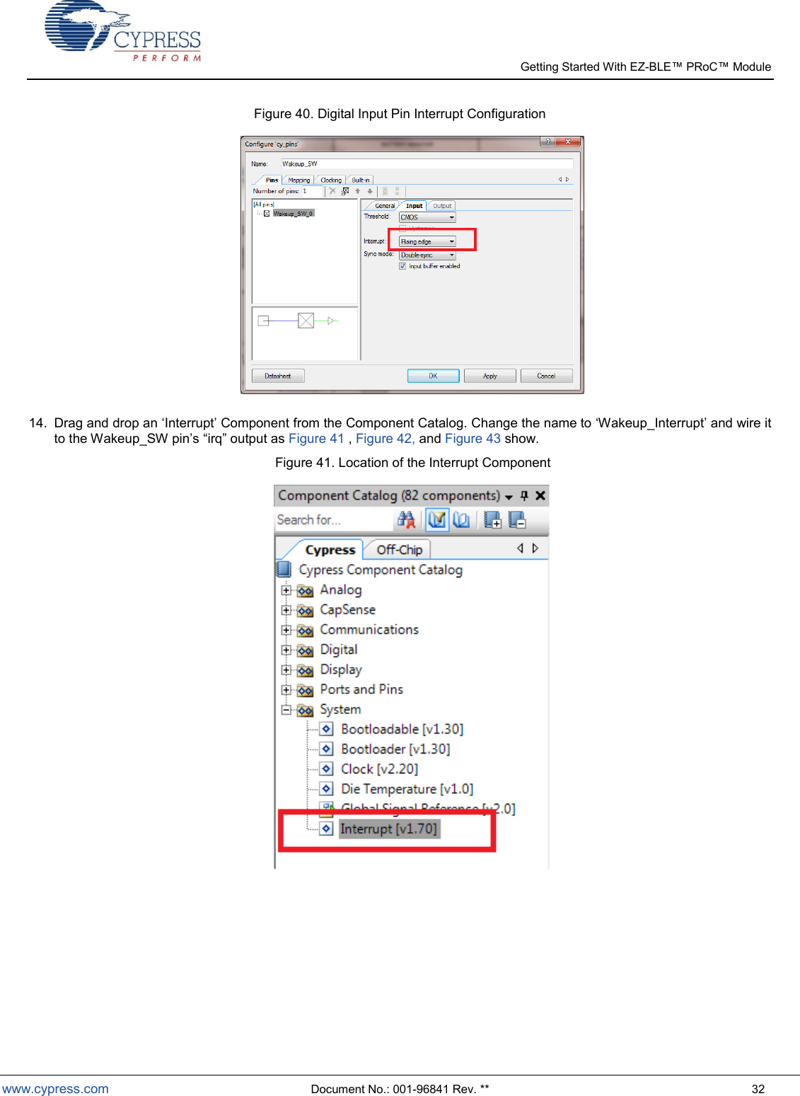
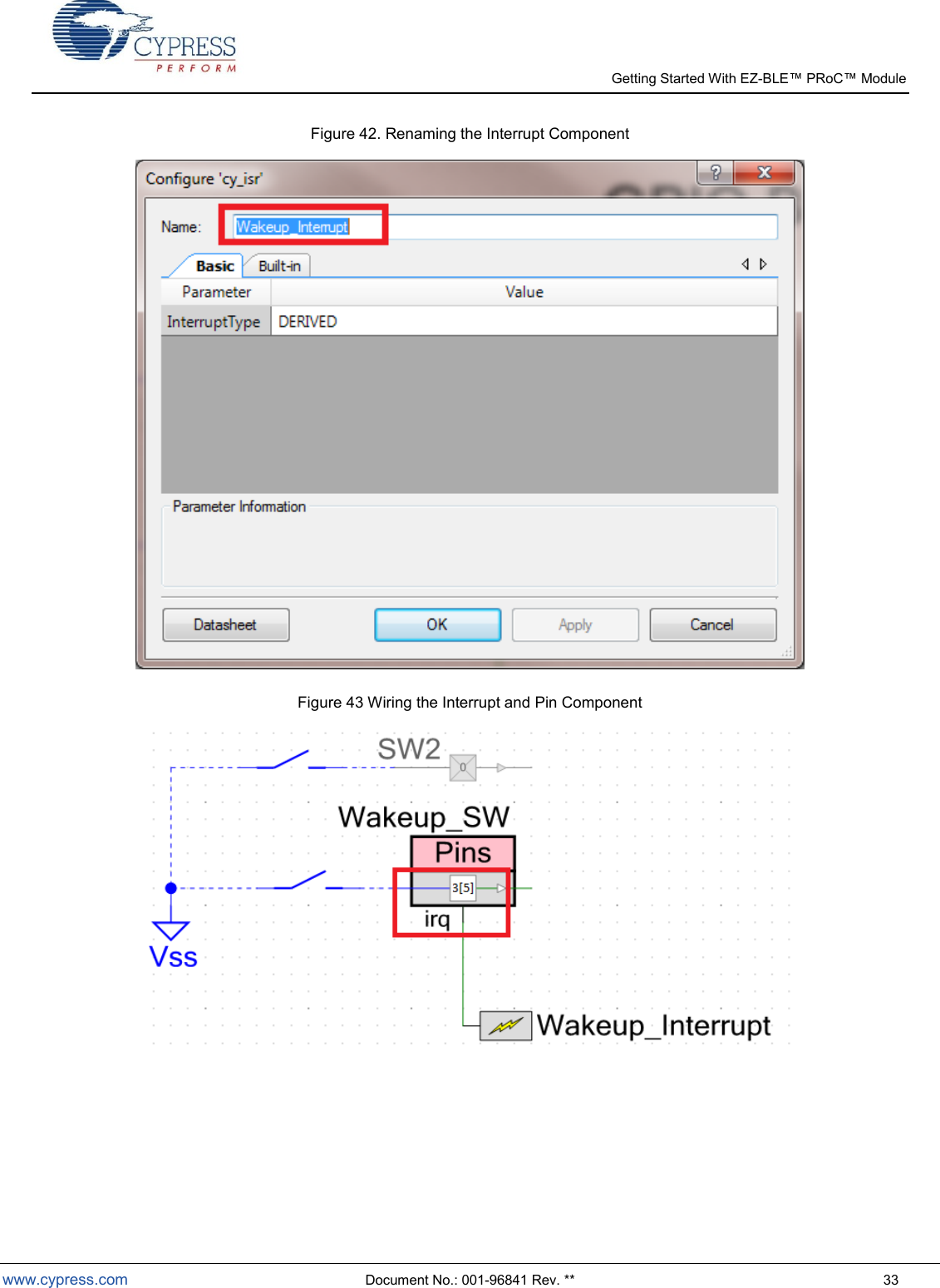
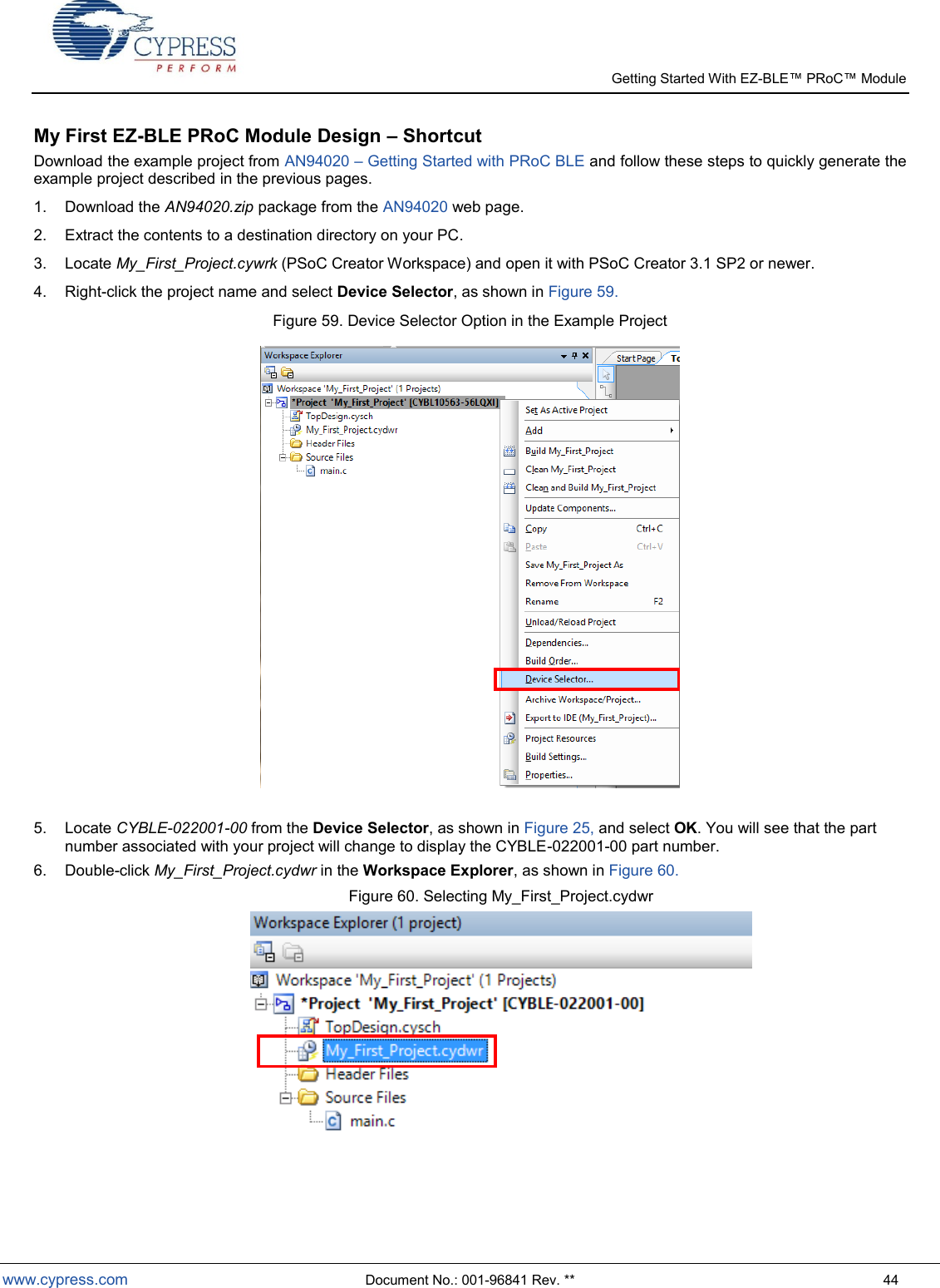
![Getting Started With EZ- www.cypress.com Document No.: 001-96841 Rev. ** 34 15. To assign pins to the LEDs and button, open the file My_First_Project.cydwr (Design-Wide Resource file) from Workspace Explorer and click the Pins tab. You can use this tab to select the device pins for the outputs (Advertising_LED, Disconnect_LED, and Alert_LED) and Wakeup_SW for input as Figure 44 shows. The following pin assignment is made with respect to the CY8CKIT-042 BLE pioneer kit and the CYBLE-022001-EVAL board connections. The LEDs on the CY8CKIT-042 BLE baseboard are mapped to P3[6] (green), P3[7] (blue), and P2[6] (red) on the Pioneer kit baseboard. These baseboard connections correspond to connections P3[6] (green), P3[7] (blue), and P3[4] (red) of the CYBLE-022001-EVAL module. The LEDs are Active low. Wakeup_SW is mapped to P2[7] of the Pioneer Kit baseboard, which is P3[5] of the CYBLE-022001-EVAL module. Refer to CYBLE-022001-EVAL Connections to CY8CKIT-042-BLE for details on the EZ-BLE PRoC Module Evaluation board connections. Figure 44.Pin Selection 16. Select Generate Application from the Build menu. Notice in the Workspace Explorer window that PSoC Creator automatically generates source code files for the Bluetooth Low Energy, Clock, and Digital Output/Input Pin Components, as Figure 45 shows. Figure 45. Generated Source Files](https://usermanual.wiki/Cypress-Semiconductor/2001/User-Guide-2607234-Page-34.png)
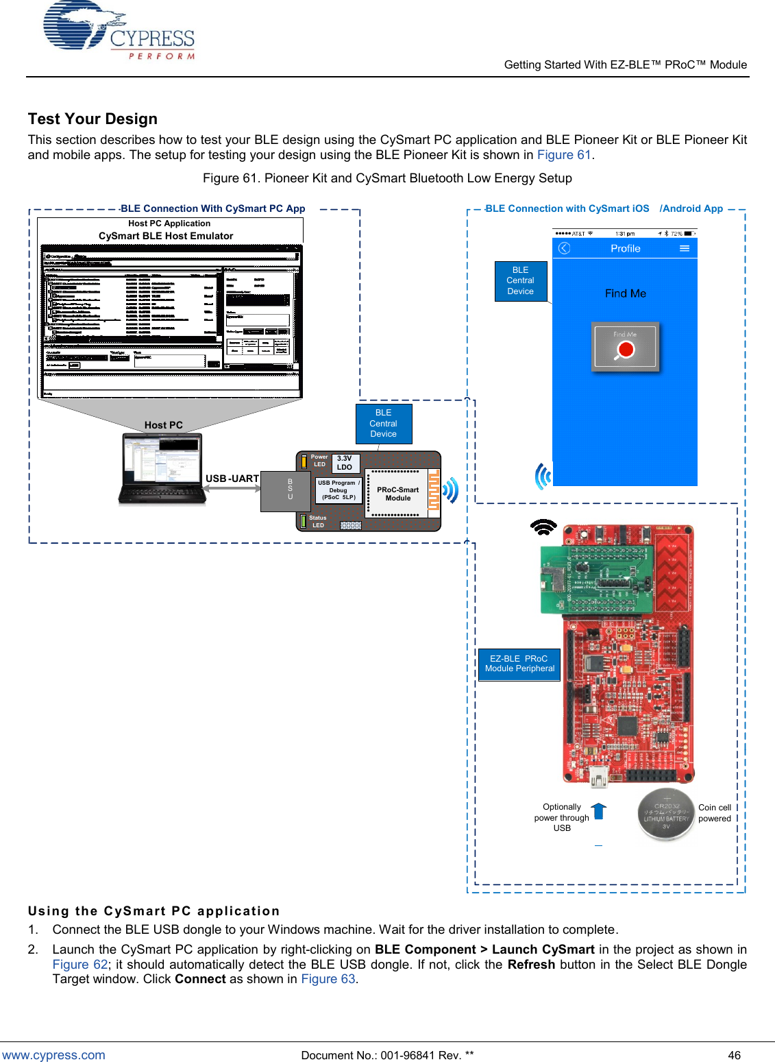
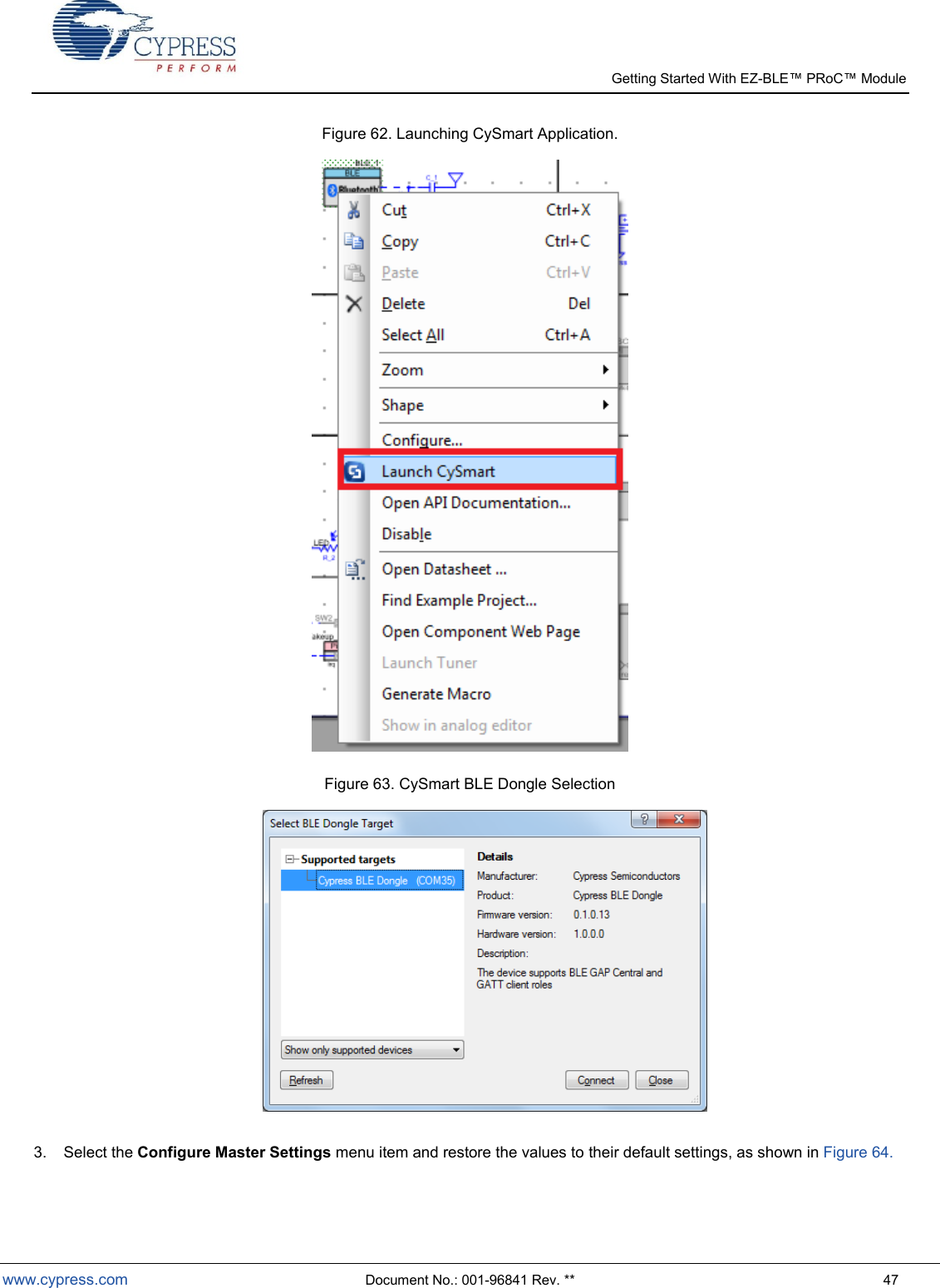
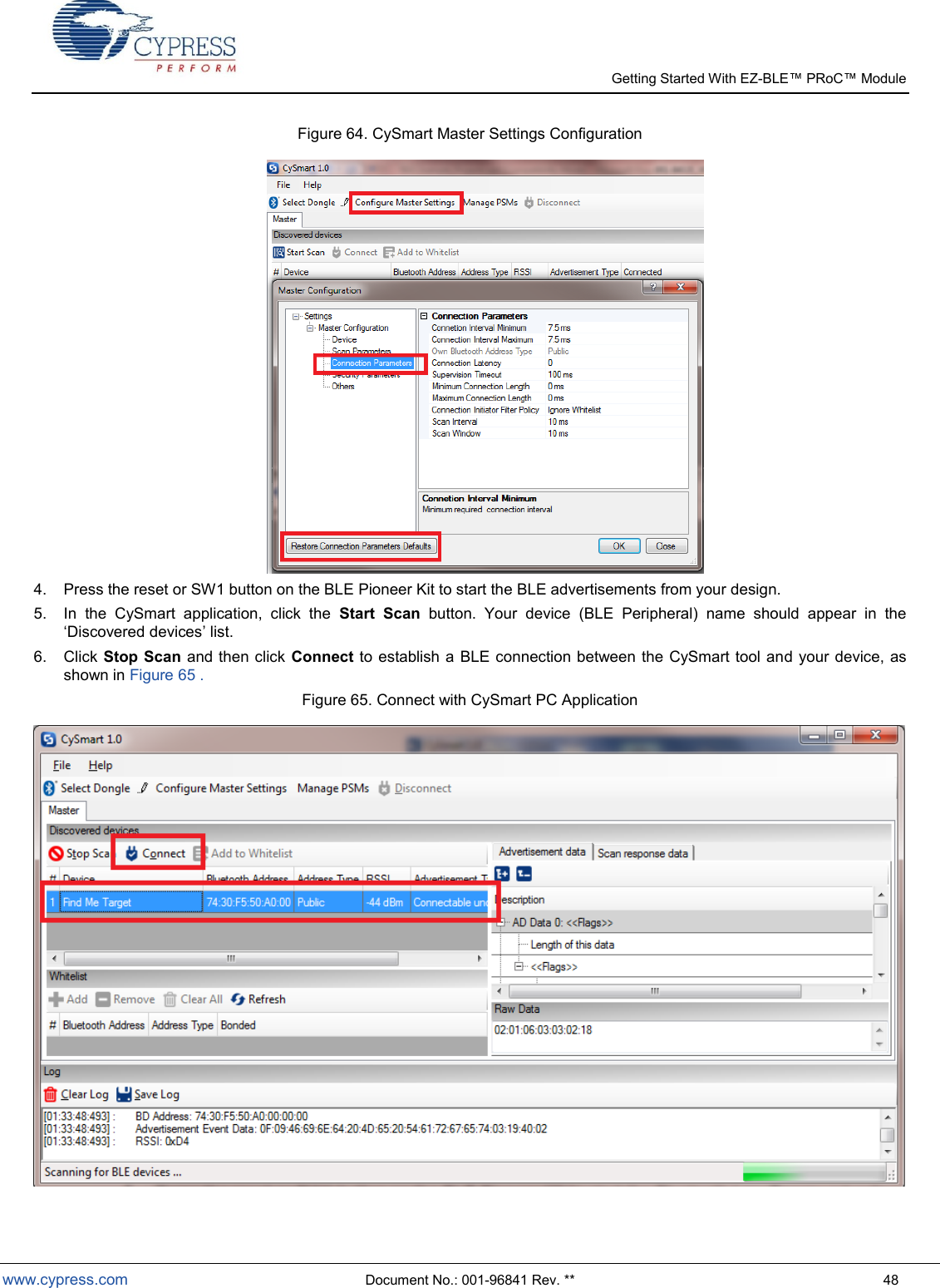
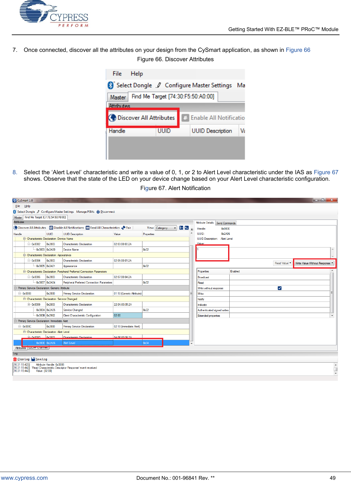
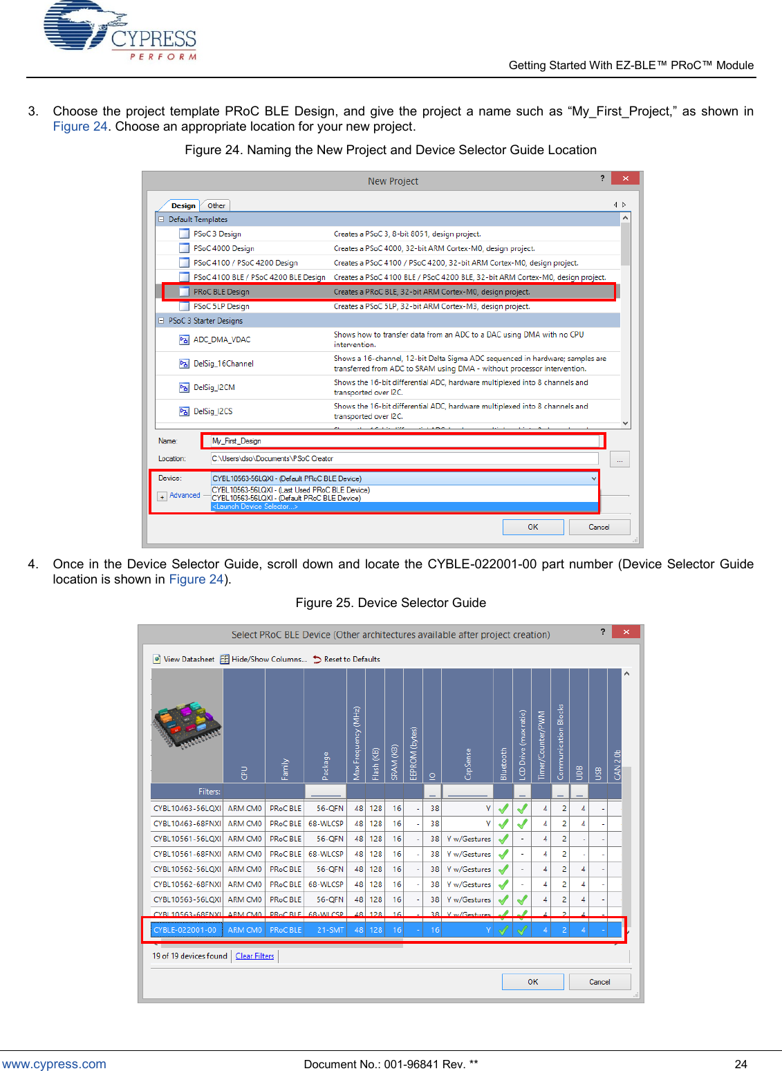
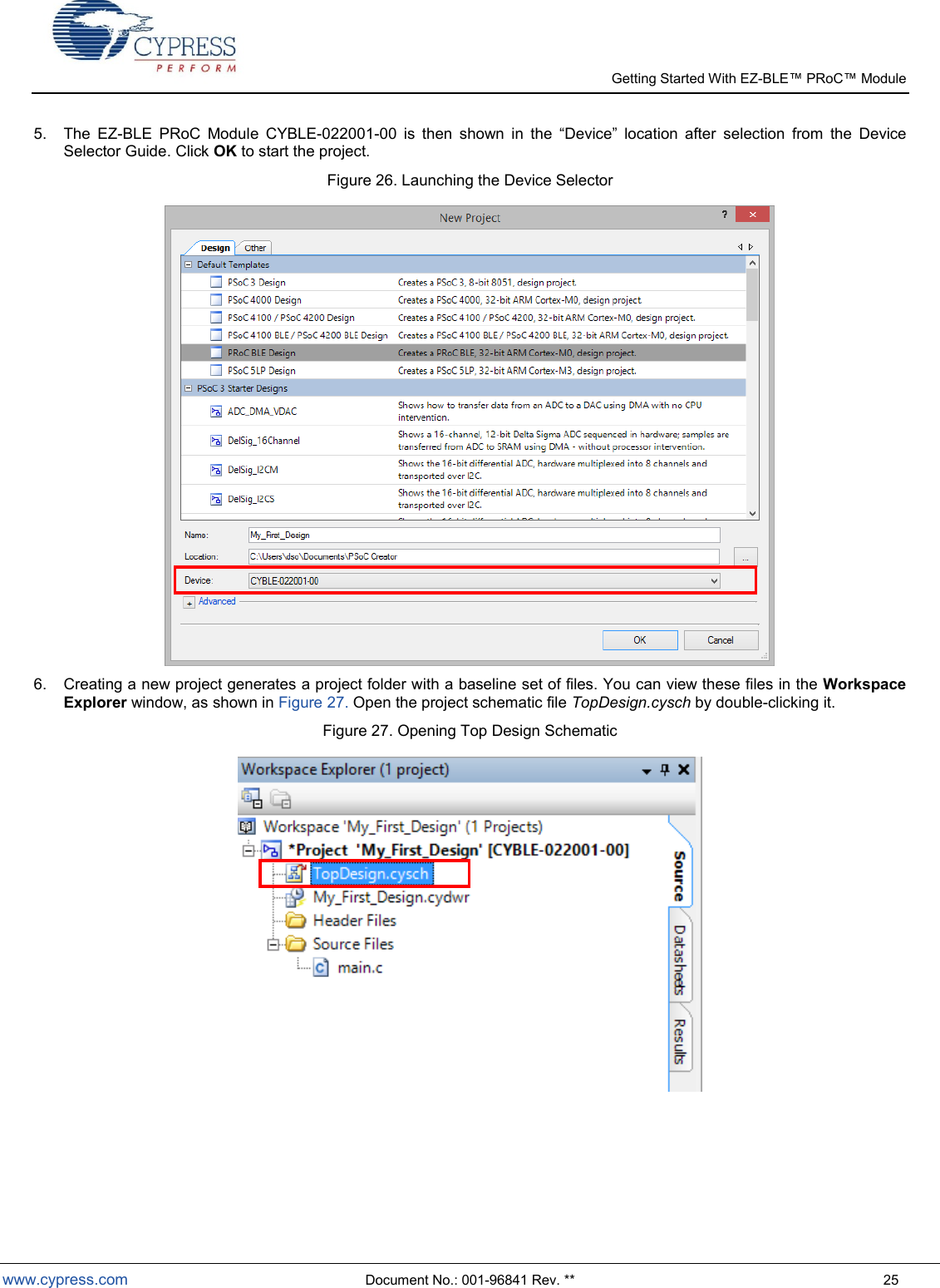
![Getting Started With EZ- www.cypress.com Document No.: 001-96841 Rev. ** 45 7. When the pin assignment table is displayed, you will notice that two of the connections have been unassigned. This is due to the limited I/O supported on the EZ-BLE PRoC Module. Both Disconnect_LED and Wakeup_SW will be shown as unassigned. 8. To complete the assignments, assign P3[4] to Disconnect_LED and P3[5] to Wakeup_SW. These connections can be determined through checking the CY8CKIT-042-BLE and CYBLE-022001-EVAL schematics. 9. Build the application as shown in Figure 54. 10. Program the CYBLE-022001-EVAL as shown in Figure 57. 11. Proceed to the next section to test your design.](https://usermanual.wiki/Cypress-Semiconductor/2001/User-Guide-2607234-Page-45.png)