Cypress Semiconductor 2001 EZ-BLE PRoC Module User Manual Manual
Cypress Semiconductor EZ-BLE PRoC Module Manual
Manual

www.cypress.com Document No.: 001-96841 Rev. ** 1
AN96841
Getting Started With EZ-BLE™ PRoC™ Module
Authors: David Solda
Associated Project: Refer to AN94020
Associated Part Family: CYBLE-022001-00
Software Version: PSoC Creator™ 3.1 SP2 and higher
Related Application Notes: For a complete list of the application notes, click here.
To get the latest version of this application note, or the associated project file, please visit
http://www.cypress.com/go/AN96841.
AN96841 introduces you to the EZ-BLE PRoC Module, a fully qualified and certified Bluetooth Low Energy (BLE)
module. The EZ-BLE PRoC Module is a complete BLE solution, integrating a BLE radio system, two crystals, chip
antenna and passive components required for BLE operation. This application note helps you explore the EZ-BLE PRoC
Module architecture and development too
development tool for the EZ-BLE PRoC Module. This application note also guides you to more resources to accelerate
in-depth learning about the Cypress BLE module solution.
Contents
Introduction ....................................................................... 2
More Information ............................................................... 2
EZ-BLE PRoC Module Overview ...................................... 3
EZ-BLE PRoC Module Mechanical Dimensions ........... 3
EZ-BLE PRoC Module Pinout and Functionality .......... 4
PRoC BLE Silicon Features ......................................... 7
Host Recommended PCB Layout ................................. 7
Bluetooth Low Energy Overview ....................................... 8
Development Tools ......................................................... 12
PSoC Creator Software .............................................. 12
Bluetooth Low Energy Component Software .............. 13
CySmart PC App ........................................................ 13
CySmart Mobile App .................................................. 14
Development Kits and Evaluation Boards ....................... 14
Learning Resources ........................................................ 21
EZ-BLE PRoC Module Datasheet .............................. 21
PRoC BLE Device Datasheet ..................................... 21
PRoC BLE Technical Reference Manual.................... 21
Learning PSoC Creator .............................................. 21
Application Notes ....................................................... 21
Design Guide .............................................................. 21
Technical Support ...................................................... 21
My First EZ-BLE PRoC Module Design ........................... 22
About the Design ........................................................ 22
Create the Design ...................................................... 23
Write the Application Code ......................................... 35
Program the Device.................................................... 43
My First EZ-BLE PRoC Module Design Shortcut .... 44
Test Your Design........................................................ 46
Summary ......................................................................... 51
Related Application Notes ............................................... 51
Appendix A: EZ-BLE PRoC Module Features ................. 52
Appendix B: Cypress Terms of Art .................................. 53
Appendix C: Code Examples .......................................... 54
Worldwide Sales and Design Support ............................. 59

Getting Started With EZ- Module
www.cypress.com Document No.: 001-96841 Rev. ** 2
Introduction
Bluetooth Low Energy (BLE) is an ultra-low-power
wireless standard defined by the Bluetooth Special
Interest Group (SIG) for low-power, short-range
communication. It features a physical layer, protocol stack,
and profile architecture, all designed and optimized for the
lowest power consumption. BLE operates in the 2.4-GHz
ISM band, with a data rate of 1 Mbps.
BLE is used in a wide range of applications. The use of
BLE in these applications also varies widely in production
volume, from very low- to high-volume end products. As
such, fully qualified, certified, BLE modules have fast
become the design preference. The use of modules
removes time consuming and costly
qualification/certification processes.
The Cypress EZ-BLE PRoC Module is a fully integrated,
qualified and certified, programmable system that
integrates 32-kHz and 24-MHz crystal oscillators, passive
components, on-board chip antenna, and s
PRoC BLE chip (BLE radio, programmable analog and
digital peripherals, memory, and an ARM® Cortex®-M0
microcontroller) on a small 10 mm × 10 mm × 1.8 mm
module.
The EZ-BLE PRoC Module enables a quick time-to-market
and eliminates costly certification and qualification
processes, offering an effective alternative to completing a
BLE system design from ground up. In addition to
reducing the cycle time, certification and qualification
expenses, the programmable peripherals and GPIOs allow
great flexibility using PSoC Creator IDE, the schematic-
based design tool for designing applications with EZ-BLE
PRoC Module, and a speedy time to market.
The BLE stack library is integrated with PSoC Creator and
is free-of-cost. It can be easily configured using a simple
graphical user interface, allowing you to jumpstart your
BLE design in minutes.
The EZ-BLE PRoC Module offers a best-in-class current
consumption of 150 nA while retaining the SRAM contents
and the ability to wake up from an interrupt. The EZ-BLE
PRoC Module consumes only 60 nA while maintaining the
wakeup capability in its nonretention power mode. The
capacitive touch-sensing feature in the EZ-BLE Module,
known as CapSense®, offers an unprecedented signal-to-
noise ratio, best-in-class waterproofing, and a wide variety
of sensor types such as buttons, sliders, and proximity
sensors that are gaining increased popularity in wearable
electronic devices such as activity monitors, health, and
fitness equipment.
If you are a first- PRoC
family of products, it is recommended that you read
Appendix B for a list of commonly used terms.
More Information
Cypress provides a wealth of data at www.cypress.com to
help you accelerate learning on the EZ-BLE PRoC
s PSoC and PRoC family of
silicon devices. If you are a first-
PSoC or PRoC family of products, it is recommended that
you read Appendix B: Cypress Terms of Art for a list of
commonly used terms.
Following is an abbreviated list of resources for the
EZ-BLE PRoC Module:
Datasheets: Describe and provide electrical
specifications for the EZ-BLE PRoC Module.
Application Notes and Code Examples: Covers a
broad range of topics, from basic to advanced level.
Many of the application notes include code examples.
PSoC Creator provides additional code examples
see Appendix C: Code Examples.
Technical Reference Manuals (TRMs): Provide
detailed descriptions of the architecture and registers
in each PSoC 4 BLE device family.
CapSense Design Guide: Learn how to design
capacitive touch-sensing applications with the EZ-BLE
PRoC Module.
Development Tools
CY8CKIT-042-BLE Bluetooth Low Energy (BLE)
Pioneer Kit is an easy-to-use and inexpensive
development platform for BLE. This kit includes
the EZ-BLE PRoC Module Evaluation daughter
board.
CySmart BLE Host Emulation Tool for Windows,
iOS, and Android is an easy-to-use GUI that
enables you to test and debug your BLE
Peripheral applications.
See Development Kits and Evaluation Boards for an
overview of available for the EZ-BLE PRoC Module.
Technical Support
Frequently Asked Questions (FAQs): Learn more
about our BLE ecosystem
BLE Forum: See if your question is already
answered by fellow developers on the PSoC 4
BLE and PRoC BLE forums.
Cypress support: Still no luck? Visit our support
page and create a technical support case or
contact a local sales representative. If you are in
the United States, you can talk to our technical
support team by calling our toll-free number: +1-
800-541-4736. Select option 8 at the prompt.
Getting Started With EZ- Module
www.cypress.com Document No.: 001-96841 Rev. ** 3
EZ-BLE PRoC Module Overview
The EZ-BLE PRoC Module (CYBLE-022001-00) is an integrated, fully certified BLE solution, which allows for rapid
development and deployment of your BLE-enabled product. This section will provide an outline of the mechanical structure of
the EZ-BLE PRoC Module. This information is necessary for customers designing their own PCB layout for this module.
The EZ-BLE PRoC Module ships with the necessary components required to achieve full BLE functionality. It includes:
PCB substrate: 10 mm × 10 mm × 0.5 mm
Cypress PRoC BLE chip (refer to PRoC BLE Silicon Features for information on the Cypress BLE chip)
Crystal oscillators
32.768 kHz watch crystal oscillator (WCO)
24.0 MHz internal main oscillator (IMO)
Chip antenna
Passives (resistor, capacitor, inductor)
Metal RF Shield
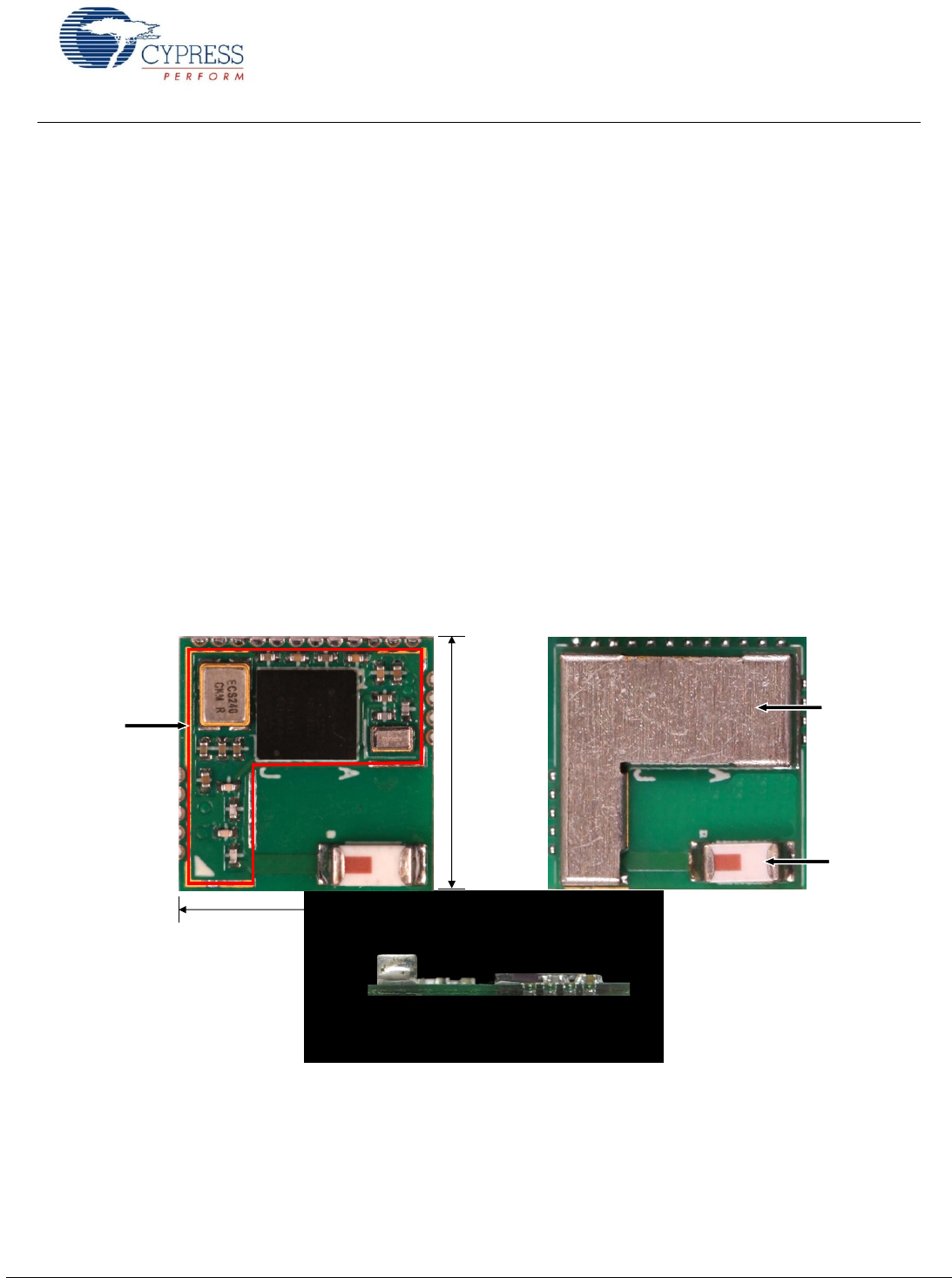
EZ-BLE PRoC Module Mechanical Dimensions
Figure 1 shows a physical picture of the EZ-BLE PRoC module.
Figure 1. EZ-BLE PRoC Module Top View (with and without Shield) and Side View
10.0 mm
Shield Outline
H = 1.10 mm
Chip Antenna
0.5 mm
1.3 mm
10.0 mm
Shield
For more details on the module dimensions, external component connections, and module placement recommendations, see
the EZ-BLE PRoC Module datasheet specification.
Getting Started With EZ- Module
www.cypress.com Document No.: 001-96841 Rev. ** 4
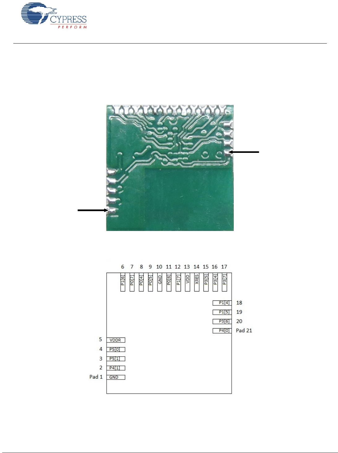
EZ-BLE PRoC Module Pinout and Functionality
The EZ-BLE PRoC Module is designed to mount as a component on an end product PCB. Only a portion of the available I/O
of the PRoC BLE silicon device are exposed on the CYBLE-022001-00 module in order to minimize the module footprint size.
The EZ-BLE PRoC Module contains 21 connections on the bottom side of the module. Figure 2 and Figure 3 detail the bottom
side connections available on the EZ-BLE PRoC Module.
Figure 2. EZ-BLE PRoC Module Bottom View (Actual Unit - Seen Through Top)
Figure 3. EZ-BLE PRoC Module Bottom View (Diagram - Seen Through Top)
Pad 1
Pad 21

Getting Started With EZ- Module
www.cypress.com Document No.: 001-96841 Rev. ** 5
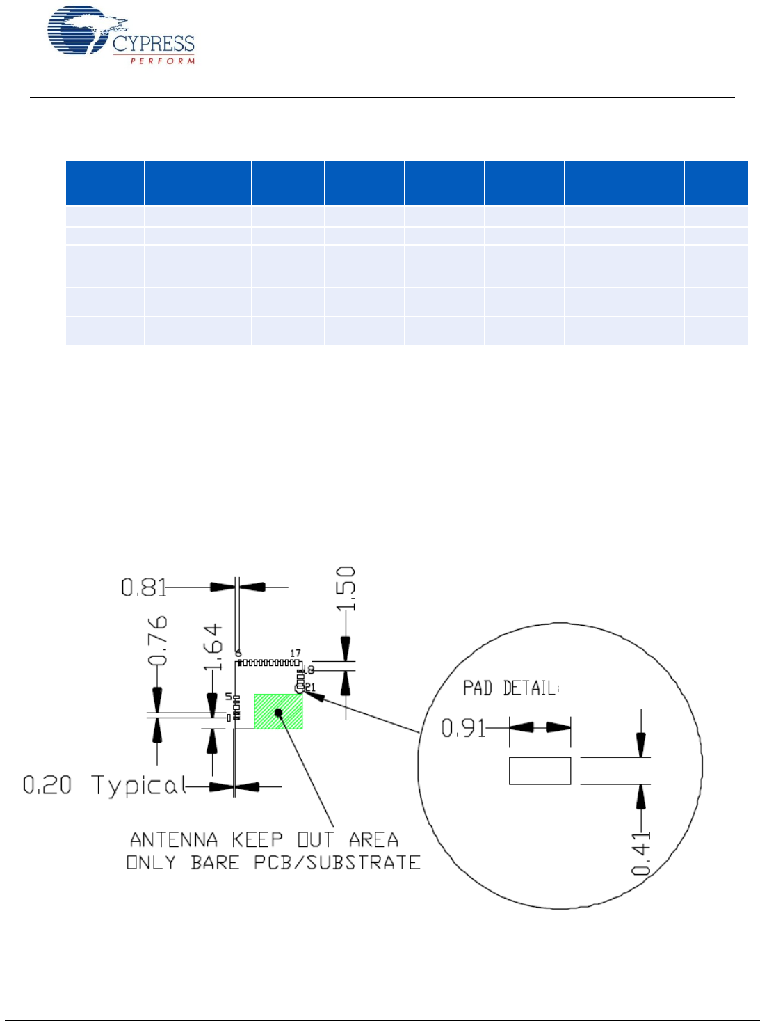
The connection pad spacing is listed in Table 1.
Table 1. EZ-BLE PRoC Module Connection Pad Spacing (Center-to-Center)
Pad X
Pad Y
Pad Pitch
(Pad X - Pad Y)
Comments
Bottom-Left Corner
1
1.64 mm
Distance from bottom left corner to Pad 1 center
1
2
0.76 mm
Distance from Pad 1 center to Pad 2 center
2
3
0.76 mm
Distance from Pad 2 center to Pad 3 center
3
4
0.76 mm
Distance from Pad 3 center to Pad 4 center
4
5
0.76 mm
Distance from Pad 4 center to Pad 5 center
Top-Left Corner
6
0.81 mm
Distance from top left corner to Pad 6 center
6
7
0.76 mm
Distance from Pad 6 center to Pad 7 center
7
8
0.76 mm
Distance from Pad 7 center to Pad 8 center
8
9
0.76 mm
Distance from Pad 8 center to Pad 9 center
9
10
0.76 mm
Distance from Pad 9 center to Pad 10 center
10
11
0.76 mm
Distance from Pad 10 center to Pad 11 center
11
12
0.76 mm
Distance from Pad 11 center to Pad 12 center
12
13
0.76 mm
Distance from Pad 12 center to Pad 13 center
13
14
0.76 mm
Distance from Pad 13 center to Pad 14 center
14
15
0.76 mm
Distance from Pad 14 center to Pad 15 center
15
16
0.76 mm
Distance from Pad 15 center to Pad 16 center
16
17
0.76 mm
Distance from Pad 16 center to Pad 17 center
Top-Right Corner
18
1.50 mm
Distance from top right corner to Pad 18 center
18
19
0.76 mm
Distance from Pad 18 center to Pad 19 center
19
20
0.76 mm
Distance from Pad 19 center to Pad 20 center
20
21
0.76 mm
Distance from Pad 20 center to Pad 21 center
A list of the available I/Os and supported functionality for each I/O is shown in Table 2.
Table 2. EZ-BLE PRoC Module Available Connections and Functionality
Module Solder Pad
Number
Silicon
Port Pin
Functionality
UART
SPI
I2C
TCPWM
CapSense
WCO
Out
EXT_CLK/
ECO_OUT
EXTPA_EN
SWD
GPIO
1
GND
Ground Connection
2
P4[1]
CTS
MISO
Yes
Sensor/CTANK
Yes
3
P5[1]
TX
SCLK
SCL
Yes
Sensor
Yes
Yes
4
P5[0]
RX
SS
SDA
Yes
Sensor
Yes
Yes
5
VDDR
Radio Power Supply 1.9V to 5.5V

Getting Started With EZ- Module
www.cypress.com Document No.: 001-96841 Rev. ** 6
Module Solder Pad
Number
Silicon
Port Pin
Functionality
UART
SPI
I2C
TCPWM
CapSense
WCO
Out
EXT_CLK/
ECO_OUT
EXTPA_EN
SWD
GPIO
6
P1[6]
RTS
SS
Yes
Sensor
Yes
7
P0[7]
CTS
SCLK
Yes
Sensor
SWDCLK1
Yes
8
P0[4]
RX
MOSI
SDA
Yes
Sensor
Yes
Yes
9
P0[5]
TX
MISO
SCL
Yes
Sensor
Yes
10
GND
Ground Connection
11
P0[6]
RTS
SS
Yes
Sensor
SWDIO1
Yes
12
P1[7]
CTS
SCLK
Yes
Sensor
Yes
13
VDD
Digital Power Supply Input 1.71 to 5.5V
14
XRES
External Reset Hardware Connection Input
15
P3[5]
TX
SCL
Yes
Sensor
Yes
16
P3[4]
RX
SDA
Yes
Sensor
Yes
17
P3[7]
CTS
MISO
Yes
Sensor
Yes
Yes
18
P1[4]
RX
MOSI
SDA
Yes
Yes
19
P1[5]
TX
MISO
SCL
Yes
Yes
20
P3[6]
RTS
Yes
Sensor
Yes
21
P4[0]
RTS
MOSI
Yes
CMOD
Yes
Low Pow e r M ode s
EZ-BLE PRoC Module supports the following five power modes as illustrated in Figure 4:
Active mode: This is the primary mode of operation. In this mode, all peripherals are available.
Sleep mode: In this mode, the CPU is in sleep mode, SRAM is in retention, and all the peripherals are available. Any
interrupt wakes up the CPU and returns the system to Active mode.
Deep-Sleep mode: In this mode, the high-frequency clock (IMO) and all high-speed peripherals are off. The WDT, LCD,
I2C/SPI, link layer, and low-frequency clock (32-kHz ILO) are available. Interrupts from GPIO, WDT, or SCBs can cause a
wakeup. The current consumption in this mode is 1.3 µA for all PRoC BLE devices in the family.
Hibernate mode: This power mode provides a best-in-class current consumption of 150 nA while retaining SRAM,
programmable logic, and the ability to wake up from an interrupt generated by a GPIO.
Stop mode: This power mode retains the GPIO states. Wakeup is possible by using the external reset (XRES) pin on the
module. The current consumption in this mode is only 60 nA.
1 SDWCLK and SWDIO connections can be multiplexed as the functional options listed in each of the respective rows and can be
used for programming without the need to reconfigure the device I/O.
Getting Started With EZ- Module
www.cypress.com Document No.: 001-96841 Rev. ** 7
Figure 4: Power Modes
Device Se c uri t y
The EZ-BLE PRoC Module provides a number of options for the protection of flash memory from unauthorized access or
copying. Each row of flash has a single protection bit; these bits are stored in a supervisory flash row.
PRoC BLE Silicon Features
The BLE device used on the EZ-BLE PRoC Module is the Cypress PRoC BLE. For additional details on this device, refer to
the PRoC BLE device datasheet.
Host Recommended PCB Layout
The recommended host PCB layout pattern is shown in Figure 5. Dimensions shown are in mm.
Figure 5. Host Board Recommended PCB Layout Pattern
Note that the pad length shown includes overhang of the pad beyond the module outline. The pad length to the edge of the
module is 0.71 mm.
Power Mode
Current
Consumption
Code
Execution
Digital
Peripherals
Available
Analog
Peripherals
Available
Clock
Sources
Available
Wake
-
Up
Sources
Wake
-
Up
Time
Active
2.2 mA @ 6 MHz
Yes
All
All
All
-
-
Sleep
1.3 mA
No
All
All
All
Any interrupt source
0
Deep
-
Sleep
1.3 uA
No
WDT,
LCD,
I
2
C/SPI,
Link
-
Layer
POR, BOD
WCO,
32
-
kHz
ILO
GPIO,
WDT, SCB
25 us
Hibernate
150 nA
No
No
POR, BOD
No
GPIO
2 ms
Stop
60 nA
No
No
No
No
XRES
2 ms
Getting Started With EZ- Module
www.cypress.com Document No.: 001-96841 Rev. ** 8
Bluetooth Low Energy Overview
The Bluetooth SIG defines Bluetooth 4.1, also known as Bluetooth Smart or Bluetooth Low Energy as the lowest-power
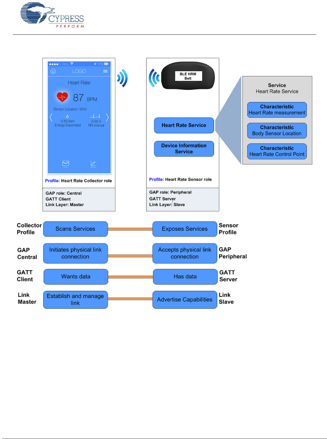
wireless standard operating in the 2.4-GHz ISM band. Figure 6 summarizes the BLE protocol stack architecture.
The following sections briefly describe the BLE stack layers. For a detailed architecture description, see the Bluetooth 4.1
specification or the training videos on the Bluetooth Developer website. If you are familiar with the Bluetooth BLE stack, you
can skip these sections. Figure 10 shows the system design for a heart rate monitoring application.
Figure 6. BLE Architecture
Physical Layer (PHY)
Link Layer (LL)
Host Control Interface (HCI)
Logical Link Control and Adaption Protocol (L2CAP)
Attribute Protocol (ATT) Security Manager (SM)
Generic Attribute Profile (GATT)
Generic Access Profile (GAP)
Heart Rate Profile
Blood Pressure Profile
Find Me Profile
Glucose Profile
Controller
Host
Applications
Phys i cal La ye r (P H Y)
The physical layer transmits or receives the digital data at
1 Mbps using GFSK modulation in the 2.4-GHz ISM band.
The BLE physical layer divides the ISM band into 40 RF
channels with a channel spacing of 2 MHz, 37 of which
are data channels and 3 are advertisement channels.
Link La ye r (LL)
The link layer implements various key functionalities that
make the BLE protocol robust and low-power. Some of
these are the following:
Adaptive Frequency Hopping (AFH) to provide RF
interference immunity
24-bit CRC and AES-128-bit encryption for robust and
secure data exchange
Advertising, scanning, creating and maintaining
connections to establish a physical link
Establishing fast connections and low duty cycle
advertising for low-power operation
Hos t Co ntr ol I nte r fac e (HCI )
HCI is the interface between the host and the controller.
This layer allows the host and the controller to exchange
information such as command, data, and events over
different transports.
Log ica l Li nk Cont r ol a nd Ada p tat ion
Pro toc o l ( L 2CAP)
L2CAP provides protocol multiplexing, segmentation, and
reassembly services to upper-layer protocols.
Segmentation and reassembly breaks the packet received
from the upper layer into smaller packets that the link layer
can transmit, and vice versa. The Bluetooth Low Energy
L2CAP layer supports three protocol channel IDs for ATT,
SM and L2CAP control. Bluetooth 4.1 allows direct data
channels through L2CAP (connection-oriented channels)
on top of these protocol channels.
Getting Started With EZ- Module
www.cypress.com Document No.: 001-96841 Rev. ** 9
Sec uri t y Man a ger (SM )
The SM layer defines the methods used for key
distribution to perform encryption and pairing.
Pairing is the process to enable security features. In
this process, two devices are authenticated, the link is
encrypted, and then keys are exchanged.
Bonding is the process in which the keys and identity
information exchanged during the pairing process are
saved within the paired devices. Bonded devices do
not have to go through the pairing process again
when reconnected.
Att rib ute P rot oco l (AT T )
ATT forms the basis of the BLE communication. This
protocol enables the client to find and access attributes on
the server. An attribute is the fundamental data-carrying
element in BLE, which consists of the following:
Attribute Handle: This is the 16-bit address assigned
by the attribute server to allow its client to identify and
access an attribute.
Attribute Type: This specifies the type of data stored
in an attribute. It is represented by a 128-bit number
called a universally unique identifier (UUID).
Bluetooth SIG defines the Bluetooth Base UUID,
which is 128 bits long. In this base UUID, typically 16
bits (32 bits for Bluetooth 4.1) are used to identify an
attribute type.
The Bluetooth Base UUID is:
0x0000xxxx-0000-1000-8000-00805F9B34FB
The 16-bit UUID of the Heart Rate Service (HRS) is
0x180D, so the complete 128-bit UUID for the HRS is
0x0000180D-0000-1000-8000-00805F9B34FB
Attribute Value: This is the actual data stored in the
attribute.
Attribute Permission: This specifies whether an
attribute can be read or written, and the security level
required. Attribute permission is set by the higher
layer specification and is not discoverable through the
attribute protocol.
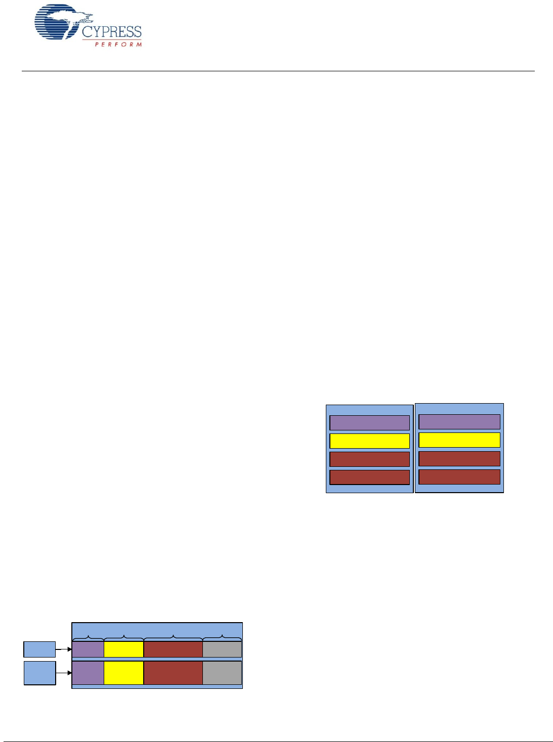
Figure 7 shows the structure of an attribute with an
example.
Figure 7. Attribute Format and Example
Attribute
Handle Attribute Type At tribute Value Attribute
Permission
2 bytes 2 bytes 0 to 512 bytes
Implementation
specific
0x0003
0x2A00
(UUID for
Device Name)
Read O nly, No
Authentication,
No Encryption
Example
Format
Several types of attributes are defined by Bluetooth SIG;
some of which are as follows:
Service: The service attribute defines the function
performed by the server. It is a collection of data
s and can also include
other services.
A service can be of two types: primary service or
secondary service. A primary service exposes the
main functionality of the device while the secondary
service provides additional functionality that a primary
service encapsulates, but that is not required to be
exposed. In a heart rate monitoring device example,
HRS is a primary service and Battery Service (BAS) is
a secondary service.
Characteristic: The characteristic attribute exposes
the data, and consists of an attribute that holds the
l
of a characteristic.
Descriptor: The descriptor is a part of the
characteristic declaration, and provides additional
information about the characteristic. Representing the
battery level in percentage values is an example of
characteristic descriptor.
Figure 8 shows the structure of a characteristic.
Figure 8. Characteristic Format and Example
<<Characteristic>>
Value
<<Descriptor>>
<<Descriptor>>
Battery Service
Battery Level
Client Characteristic
Configuration Descriptor
Characteristic
Presentation Format
Attribute Operations: These are accessed using the
following five basic methods:
Read Request: Sent by the client to read an
attribute value. For every request, the server
sends a response to the client.
Write Request: Sent by the client to write an
attribute value. The sever responds to the client
confirming whether the value is written.
Write Command: Sent by the client to the server
to write an attribute value. The server does not
send any response for the write command.
Notification: Sent by the server to the client to
notify a new value or a change in value. The client
does not send any response for a notification
command.
Indication: A type of notification from the server
that is always confirmed by the client.
Getting Started With EZ-
www.cypress.com Document No.: 001-96841 Rev. ** 10
Figure 10 shows the services and characteristics
implemented in the peripheral.
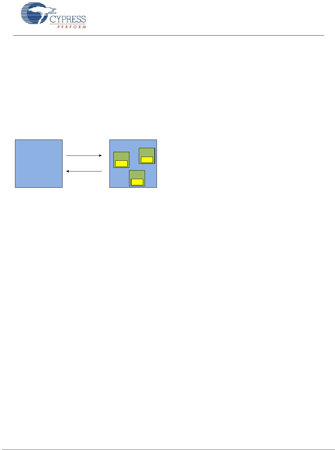
Gen e r ic A t tr ib u te P r o fi le (G ATT )
GATT defines the ways in which the attributes can be
found and used. GATT operates in one of two roles:
GATT client: The device that requests the data.
GATT server: The device that provides the data.
Figure 9 shows the client-server architecture in the GATT
layer.
Figure 9. Client-Server Architectures
Client Server
Service
Char.
Service
Char.
Service
Char.
Requests
Responses
Figure 10 shows an example in which a smartphone is
configured as the GATT client (wants data) and a heart
rate sensor that is configured as the GATT server (has
data).
Gen e r ic A c ce s s P ro fil e (G AP)
The GAP layer provides the device-specific information:
device address, device name, and how it can be
discovered and connected.
Profile: This specification defines how devices connect to
each other to find and use services. It describes the type
of application and general expected behavior of that
device. Figure 10 shows an example of a Heart rate
monitor Profile.
The GAP layer operates in one of four roles:
Broadcaster: This is a non-connectable advertising
role that is used to broadcast its data, but cannot form
BLE connections. A typical example of a GAP
broadcaster is iBeacon.
Observer: This is a listening role that scans for
advertisements. It is capable of connections but
cannot initiate one. A typical example of a GAP
observer is a packet sniffer.
Peripheral: This is a connectable advertising role that
operates as a slave after a connection is established.
For example, a heart-rate sensor reporting the
measured heart-rate to a remote device operates as a
GAP peripheral.
Central: This is a GAP role that scans for
advertisements and initiates connections. It operates
as a master after a connection is established. For
example, a mobile device retrieving the heart-rate
measurement from a peripheral heart-rate sensor
operates as a GAP central.
Figure 10 shows an example where a smartphone in
which the heart rate app operates as a GAP central and
the heart-rate sensor operates as a GAP peripheral.
Getting Started With EZ-
www.cypress.com Document No.: 001-96841 Rev. ** 11
Figure 10. Bluetooth Low Energy System Example
In Figure 10, the heart rate monitoring device operates as the GAP peripheral and implements the heart rate sensor profile,
while the smartphone receiving the data operates as the GAP central and implements the heart rate collector profile.
the heart rate service that comprises three
characteristics (the Heart Rate Measurement Characteristic, the Body Sensor Location Characteristic, and the Heart Rate
Control Point Characteristic) and the Device Information Service. At the link layer, heart rate measurement device is the slave
and the smartphone is the master
Getting Started With EZ-
www.cypress.com Document No.: 001-96841 Rev. ** 12
Development Tools
Cypress supports the EZ-BLE PRoC Module with high-quality software tools and development kits. They provide access to a
suite of world-class Integrated Design Environments (IDEs). PSoC Creator is a single IDE to develop application code and
then build, debug, and deploy an embedded design.
Cypress provides the following software and hardware tools, to get started with a EZ-BLE PRoC Module based design:
1. PSoC Creator IDE
2. Bluetooth Low Energy Component (part of PSoC Creator)
3. CySmart PC application
4. CySmart Android app
5. CySmart iOS app
6. Bluetooth Low Energy Development Kit (CY8CKIT-042)
7. EZ-BLE PRoC EVAL Board (CYBLE-022001-EVAL)
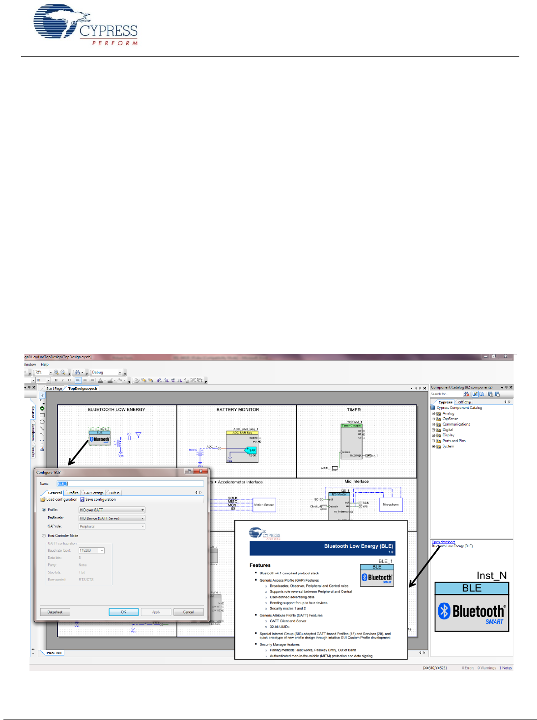
PSoC Creator Software
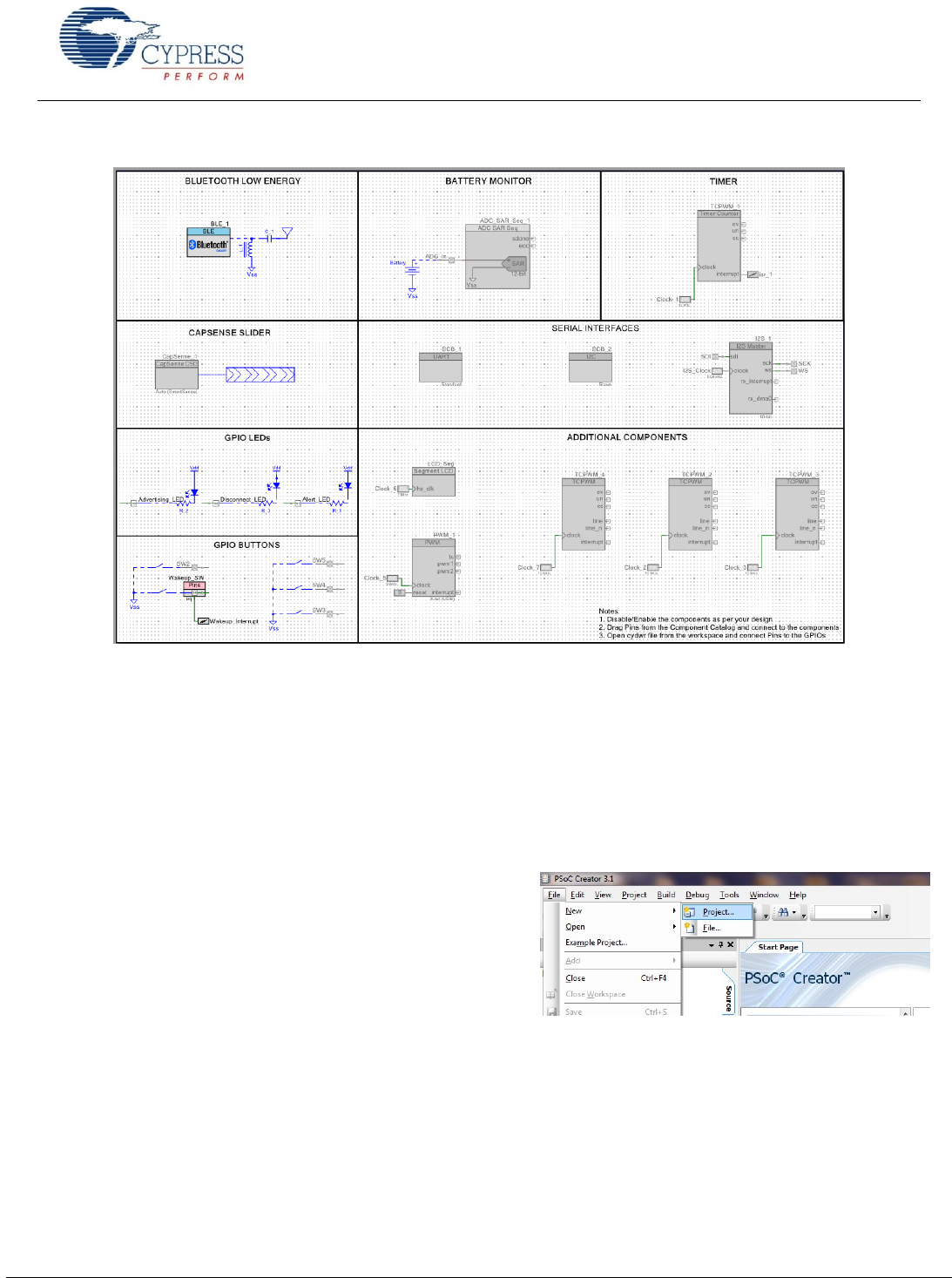
PSoC Creator is a state-of-the-art, easy-to-use IDE. It offers a unique combination of hardware configuration and software
development based on standard schematic entry, as Figure 11 shows. You can customize each Component using a
configuration window. Every Component comes with a detailed Component datasheet.
For EZ-BLE PRoC Module, you can use the initial designs in which the components are pre-configured and pre-populated.
You can also develop applications in a drag-and-drop design environment using a library of pre-characterized, production-
ready Components.
For details, see the PSoC Creator home page.
Figure 11. PSoC Creator Schematic Entry and Components
Getting Started With EZ-
www.cypress.com Document No.: 001-96841 Rev. ** 13
Bluetooth Low Energy Component Software
The Bluetooth Low Energy Component provides a comprehensive GUI-based configuration window that lets you quickly
design applications that require BLE connectivity. The Component incorporates a Bluetooth Core Specification v4.1 compliant
BLE protocol stack and provides API functions to enable user applications to interface with the underlying Bluetooth Low
Energy Sub-System (BLESS) hardware via the stack.
The Component supports the SIG-adopted GATT-based profiles and services as well as custom BLE profiles and services,
and it allows various GAP and GATT roles to be configured. The Component generates the necessary code for a particular
profile and service operation, as configured in the GUI, abstracting the underlying BLE stack and hardware configuration so
that you can concentrate on the system design.
The BLE Component also provides profile Application Programming Interfaces (APIs) to design BLE solutions without
requiring manual stack-level manipulation. The exception to this is the L2CAP configuration specified in Bluetooth v4.1, which
allows advanced users to configure the L2CAP layer of the stack if desired.
Developing Bluetooth Low Energy Application involves four easy steps. For detailed information, refer to AN94020 Getting
Started with PRoC BLE.
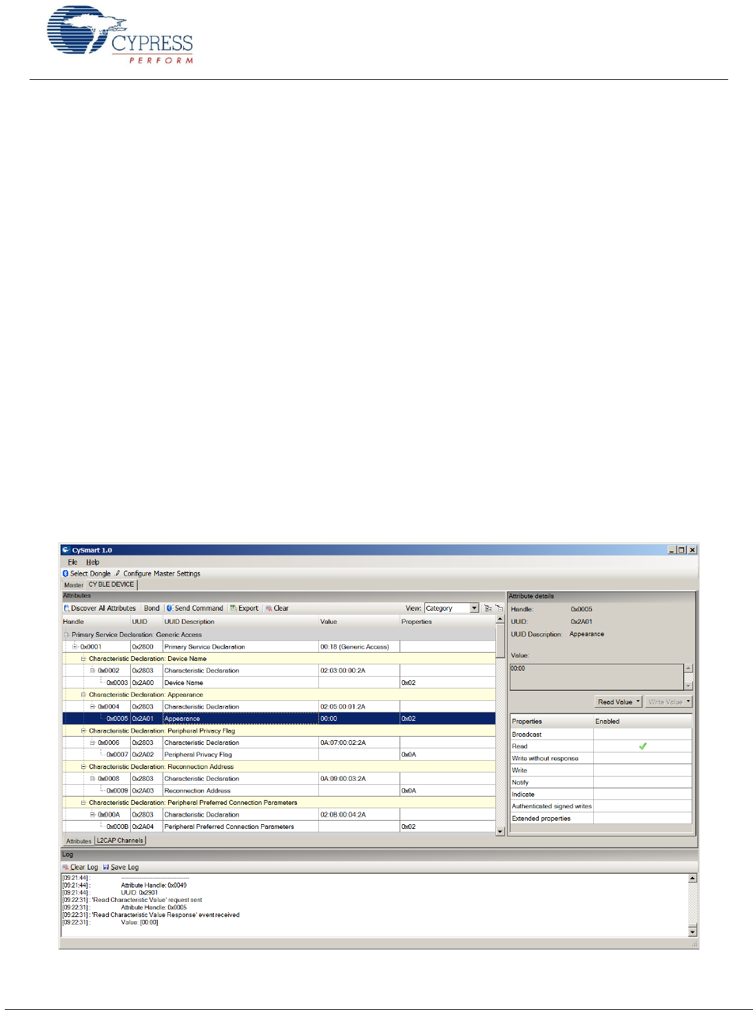
CySmart PC App
The Bluetooth Low Energy CySmart (Figure 12 ) is a Windows-based tool that provides a host emulation software platform for
testing and debugging LE peripheral or sensor applications. The tool provides an easy-to-use graphical user interface (GUI) to
enable customers to configure, test and debug their solutions. The tool is available as an independent software application and
can be launched from the PSoC Creator IDE as shown in Figure 62.
CySmart, along with a Cypress BLE dongle, acts as a master device. The tool supports the Bluetooth 4.1 specification and
can connect to any Bluetooth 4.1 or 4.0 enabled BLE peripheral devices. Comprehensive test scenarios can be created
by configuring the scan, connection and security parameters. The tool provides the ability to analyze advertisement
data and scan response data, and explore the Generic Attribute Profile (GATT) database of peripheral device. For more
information, refer to CySmart User Guide.
Figure 12. CySmart Tool Window
Getting Started With EZ-
www.cypress.com Document No.: 001-96841 Rev. ** 14
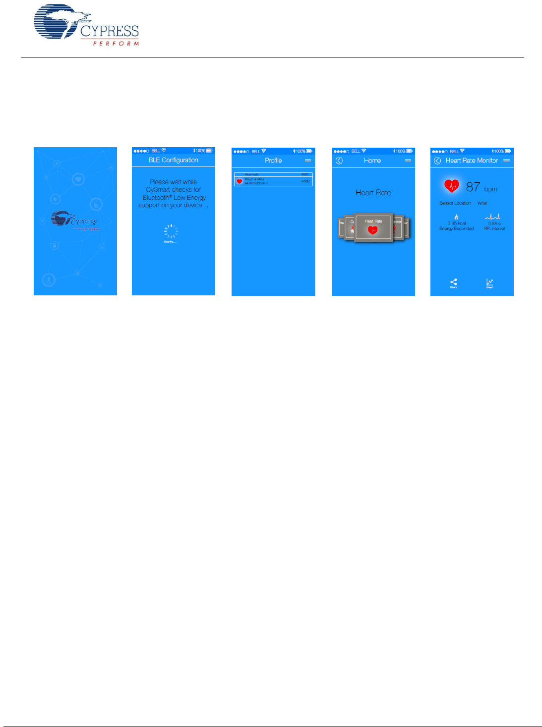
CySmart Mobile App
In addition to the PC application, you can download the CySmart mobile app for iOS or Android from the respective app
stores. The apps use the iOS Core Bluetooth framework and Android built-in platform framework for BLE to configure your
BLE-enabled mobile as a BLE central device that can scan and connect to BLE peripheral devices.
Figure 13. CySmart Heart Rate Profile
The mobile app supports Bluetooth SIG-adopted BLE standard profiles through an intuitive GUI and abstracts the underlying
BLE and characteristic details.
Development Kits and Evaluation Boards
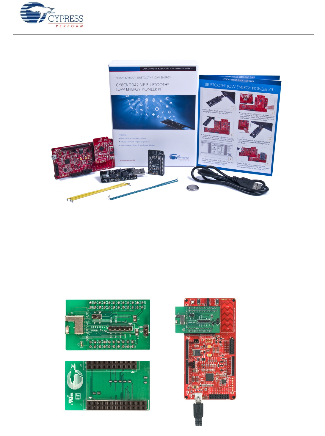
Cypress provides an easy-to-use development kit to help you prototype your EZ-BLE PRoC Module design.
CY8CKIT-042 BLE Pioneer Kit
The CY8CKIT-042 BLE Pioneer Kit shown in Figure 14 is an Arduino Uno-compliant BLE development kit for the PRoC BLE
family of devices, including the CYBLE-022001-00 module. The CY8CKIT-042 BLE kit consists of pluggable BLE modules that
connect to a baseboard. The Pioneer Kit is powered through the USB interface or with a coin cell battery.
The Pioneer baseboard and RF module combination enables you to develop battery-operated low-power BLE designs that
work in conjunction with standard Arduino shields and additional PSoC 4 BLE device capabilities such as the CapSense user
interface on the Pioneer baseboard.
The kit also contains a BLE USB dongle that acts as a BLE master and works with the CySmart application to provide a BLE
master emulation platform on non BLEWindows systems.
Cypress also provides an adapter board for the EZ-BLE PRoC Module to evaluate and develop with the Cypress module
without the need to develop custom hardware.
Getting Started With EZ-
www.cypress.com Document No.: 001-96841 Rev. ** 15
Figure 14. BLE Pioneer Kit
The kit includes of a set of BLE example projects and documentation that should help you get started with developing your
own BLE applications. Visit www.cypress.com/go/CY8CKIT-042-BLE to get latest updates on the kit and to download kit
design, example projects and documentation files.
CYB LE -022001- E V AL E Z - BL E P R o C M o d u l e E v a l u at i on Boa rd
The EZ-BLE PRoC Module Evaluation board (CYBLE-022001-EVAL) is a simple evaluation board designed to fan out the
EZ-BLE PRoC Module (CYBLE-022001-00) connections to headers compatible with the CY8CKIT-042-BLE Pioneer Kit.
The CYBLE-022001-EVAL board is used to evaluate the Cypress EZ-BLE PRoC Module without your having to design custom
hardware to mount the Cypress EZ-BLE PRoC Module.
Figure 15 shows the CYBLE-022001-EVAL connected to the CY8CKIT-042-BLE Kit.
Figure 15. CYBLE-022001-EVAL (Left) Connected to CY8CKIT-042-BLE (Right)
Getting Started With EZ-
www.cypress.com Document No.: 001-96841 Rev. ** 16
The CYBLE-022001-EVAL board contains the following components:
Cypress EZ-BLE PRoC Module (CYBLE-022001-00) soldered directly to the Evaluation Board
PCB substrate used for I/O fan out
Connection headers
Cmod capacitor (for use with Capacitive Sensing elements on the CY8CKIT-042-BLE kit)
Inductors (power supply see the datasheet specification for recommended external components)
This evaluation board is designed to simulate the placement and connection of the EZ-BLE PRoC Module in a final
application. All host-side layout pattern recommendations (as shown in Figure 5) are followed in the evaluation board.
Note that not all connections available on the CY8CKIT-042-BLE are populated on the CYBLE-022001-00/CYBLE-022001-
EVAL modules. This is due to the number of I/Os supported on the CYBLE-022001-00 module. When designing applications,
PSoC Creator will only display connections that are available on the CYBLE-022001-00 module and CYBLE-022001-EVAL.
The next page will describe in detail the connections of the CYBLE-022001-EVAL board and the corresponding connections
on the CY8CKIT-042-BLE development kit.
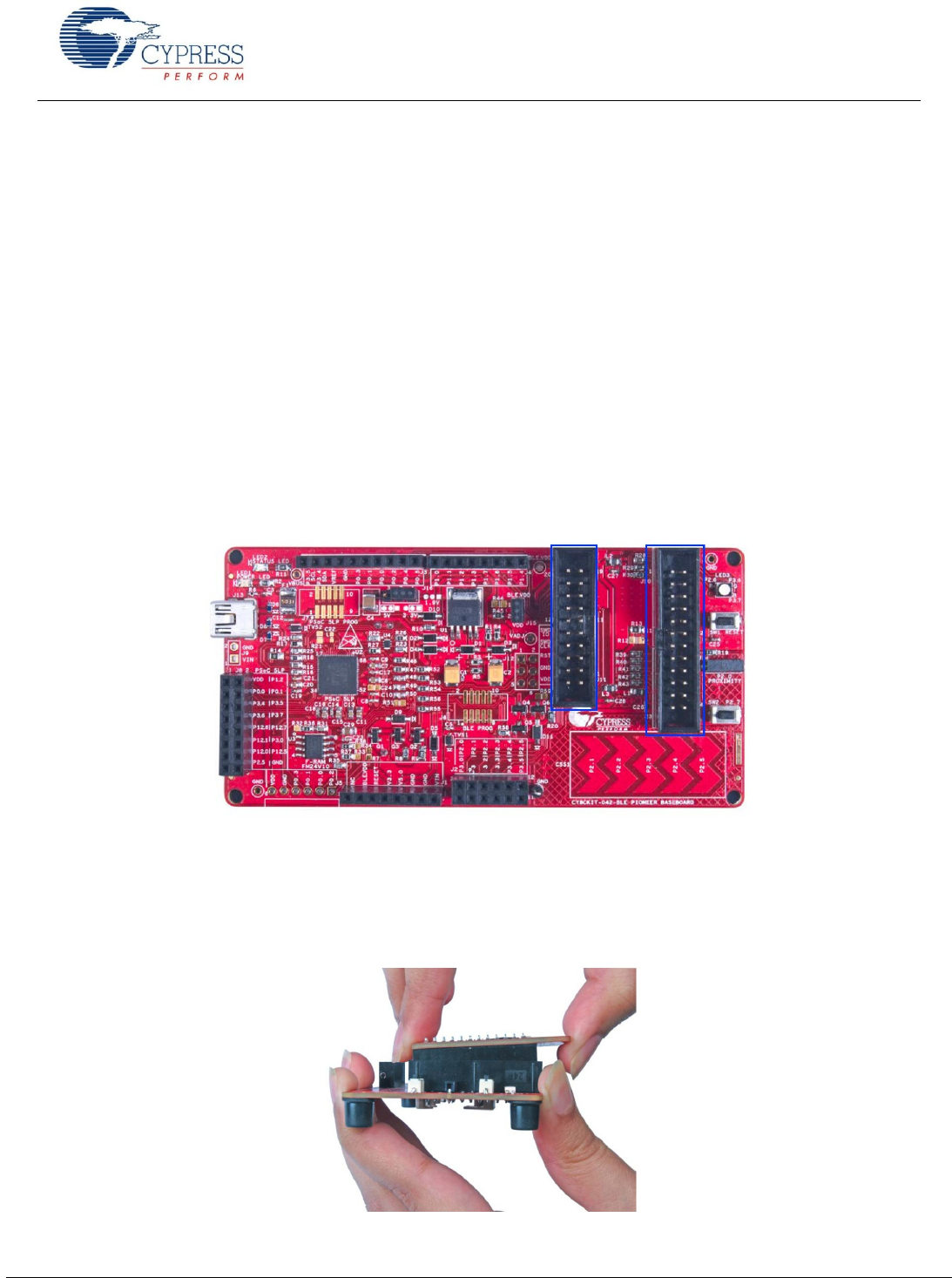
To place the CYBLE-022001-EVAL on the CY8CKIT-042-BLE baseboard, locate the 20-pin (J11) and 24-pin (J10) connection
headers, as shown in Figure 16.
Figure 16. CY8CKIT-042-BLE Baseboard with J10 and J11 Headers to Connect the CYBLE-022001-EVAL
Plug the CYBLE-022001-EVAL module into the CY8CKIT-042-BLE baseboard on headers J10 and J11, while keeping the
antenna directed outside.
To remove the CYBLE-022001-EVAL evaluation board from the CY8CKIT-042-BLE baseboard, hold the CY8CKIT-042-BLE
baseboard in one hand and the CYBLE-022001-EVAL in the other, as shown in Figure 17, and pull it out using a rocking
motion.
Figure 17. Removing the CYBLE-022001-EVAL from the CY8CKIT-042-BLE Baseboard
Getting Started With EZ-
www.cypress.com Document No.: 001-96841 Rev. ** 17
CYB LE -022001- E V AL C o n ne c ti on s to C Y 8 C KI T -042- B L E
The CYBLE-022001-00 module contains 21 connections on the back side of the module. Each of these connections is present
on the CYBLE-022001-EVAL evaluation board too.
Figure 18 shows the CYBLE-022001-EVAL and highlights the elements on the top side of the board.
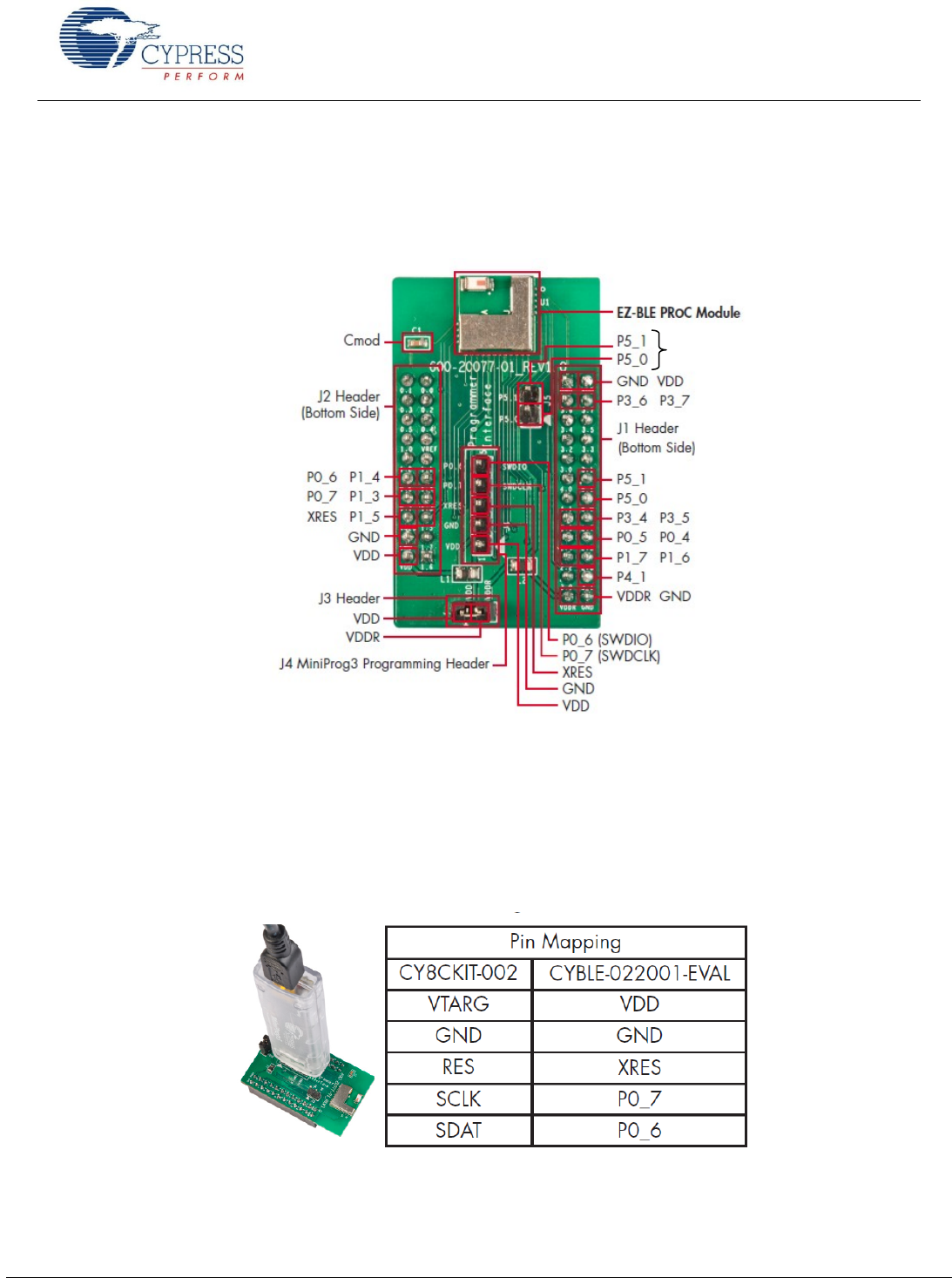
Figure 18. CYBLE-022001-EVAL Board Top Side
The CYBLE-022001-EVAL also includes the following elements:
Cmod: A 2.2-nF capacitor mounted on the evaluation board used with the CY8CKIT-042-BLE capacitive sensing slider,
buttons and proximity sensors.
J3 Header: A two-pin header that exposes VDD and VDDR.
J4 Header: A five-pin header that exposes connections used for programming the EZ-BLE PRoC Module Evaluation
board by using the MiniProg3 kit, as shown in Figure 19.
Figure 19. CYBLE-022001-EVAL Using CY8CKIT-002 MiniProg3
J5: A header that exposes P5[0] and P5[1], which can be used for I2C communication (including high speed I2C) to the
EZ-BLE PRoC Module.
J5 Header
Getting Started With EZ-
www.cypress.com Document No.: 001-96841 Rev. ** 18
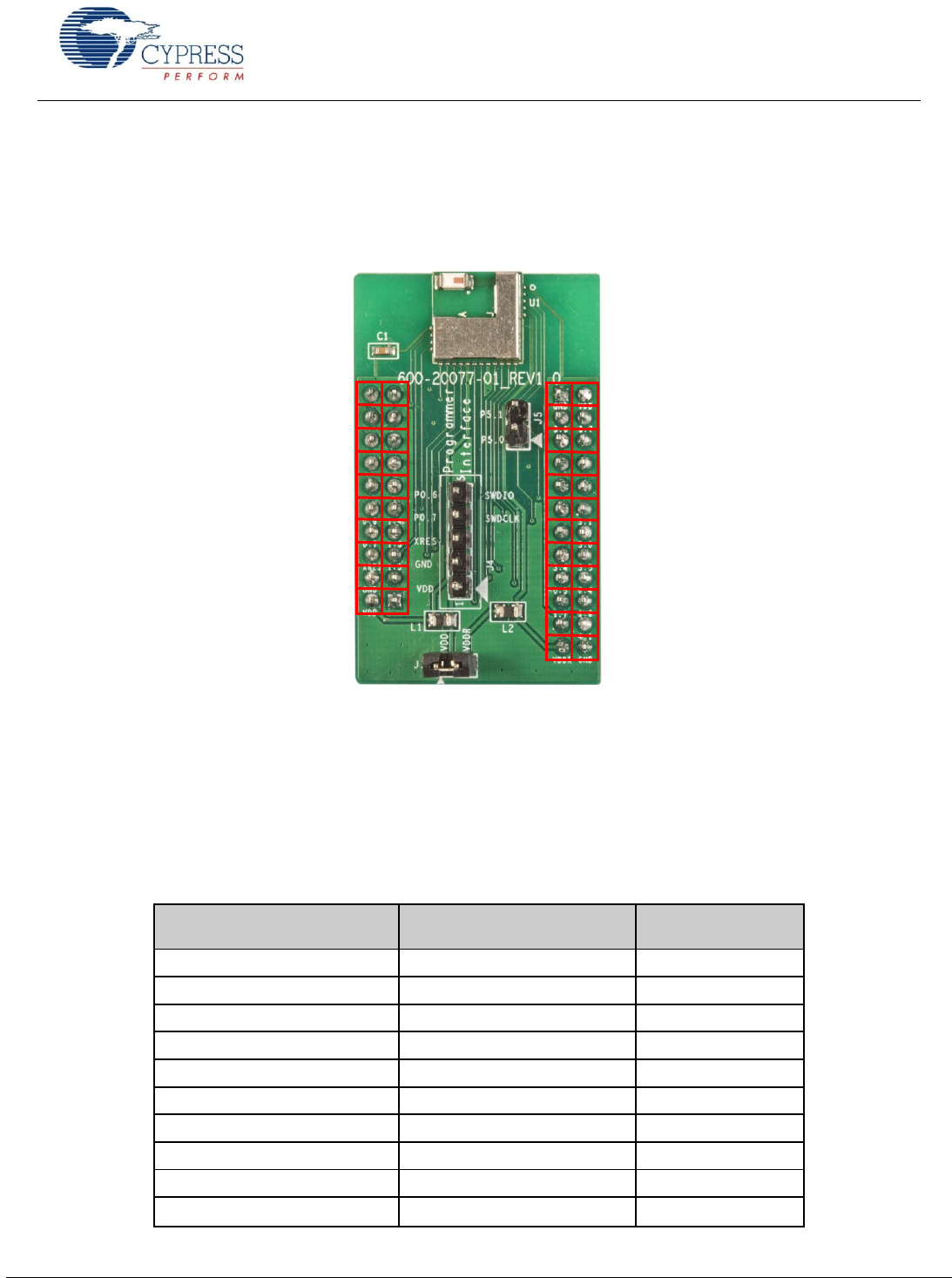
Figure 20 reiterates the Port-Pin connections on the CYBLE-022001-EVAL board.
where no physical connection is present between the EZ-BLE PRoC Module and the CYBLE-022001-EVAL board.
Figure 20. CYBLE-022001-EVAL Board Pinout
As mentioned previously, the Port-Pin connections above do not completely match the CY8CKIT-042-BLE baseboard pin out.
Seven such connections exist that do not align with the CY8CKIT-042-BLE baseboard (highlighted in red in Figure 20).
Table 3 details all connections on the CY8CKIT-042-BLE baseboard and provides the equivalent Port-Pin connection on the
CYBLE-022001-EVAL board.
Table 3. CYBLE-022001-EVAL Port-Pin Connections to CY8CKIT-042-BLE Baseboard
CY8CKIT-042-BLE Baseboard Connection
Header
CY8CKIT-042-BLE Baseboard
Connection Port-Pin2
CYBLE-022001-EVAL
Connection Port-Pin
J11
P0_0
NC
J11
P0_1
NC
J11
P0_2
NC
J11
P0_3
NC
J11
P0_4
NC
J11
P0_5
NC
J11
VREF
NC
J11
P1_0
NC
J11
P1_1
NC
J11
P1_2
NC
NC NC
NC NC
NC NC
NC NC
NC NC
P0_6 P1_4
P0_7 P1_3
XRES P1_5
GND NC
VDD NC
GND VDD
P3_6 P3_7
NC NC
NC NC
NC NC
NC P5_1
NC P5_0
P3_4 P3_5
P0_5 P0_4
P1_7 P1_6
NC P4_1
VDDR GND

Getting Started With EZ-
www.cypress.com Document No.: 001-96841 Rev. ** 19
CY8CKIT-042-BLE Baseboard Connection
Header
CY8CKIT-042-BLE Baseboard
Connection Port-Pin2
CYBLE-022001-EVAL
Connection Port-Pin
J11
P1_4
P1_4
J11
P0_6
P0_6
J11
P1_3
P1_3
J11
P0_7
P0_7
J11
P1_5
P1_5
J11
XRES
XRES
J11
P1_7
NC
J11
GND
GND
J11
P1_6
NC
J11
VDD
VDD
J12
GND
GND
J10
VDD
VDD
J10
P3_6
P3_6
J10
P3_7
P3_7
J10
P3_4
NC
J10
P3_5
NC
J10
P3_2
NC
J10
P3_3
NC
J10
P3_0
NC
J10
P3_1
NC
J10
P4_0
NC
J10
P5_1
P5_1
J10
P4_1
NC
J10
P5_0
P5_0
J10
P2_6
P3_4
J10
P2_7
P3_5
J10
P2_4
P0_5
J10
P2_5
P0_4
J10
P2_2
P1_7
J10
P2_3
P1_6
J10
P2_0
NC
J10
P2_1
P4_1
J10
VDDR
VDDR
J10
GND
GND
Note The port-pin list order is according on the CY8CKIT-042-BLE baseboard physical connection pinout.
Getting Started With EZ-
www.cypress.com Document No.: 001-96841 Rev. ** 20
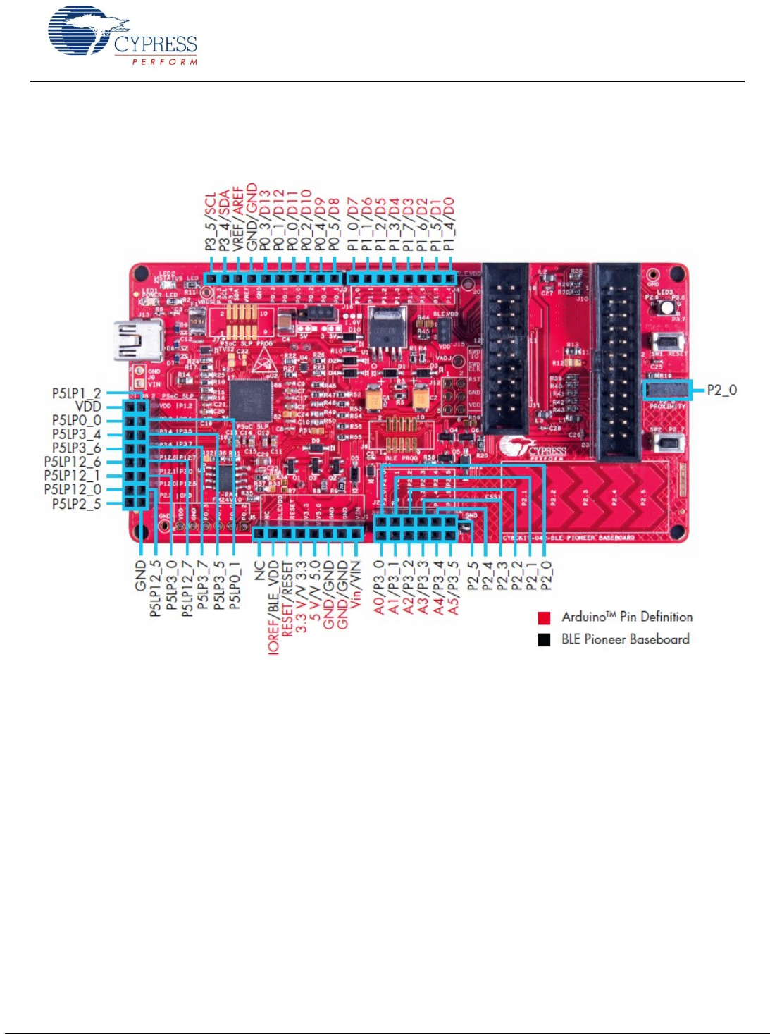
The connections shown in Table 3 apply to the Arduino compatible headers located on the CY8CKIT-042-BLE baseboard.
Figure 21 shows the Arduino compatible headers located on the CY8CKIT-042-BLE baseboard.
Figure 21. Arduino Compatible Headers on CY8CKIT-042-BLE Baseboard
Connections above are labeled according to the CY8CKIT-042-BLE baseboard pinout. For the equivalent and available
connections used with the CYBLE-022001-EVAL board, refer to Table 3. For additional information, refer to the CY8CKIT-042-
BLE product webpage.

Getting Started With EZ-
www.cypress.com Document No.: 001-96841 Rev. ** 21
Learning Resources
This section provides a list of EZ-BLE PRoC Module learning resources that can help you to get started and to develop
complete applications with EZ-BLE PRoC Module. You can also use the Document Manager in PSoC Creator to view these
resources. To open the Document Manager, choose the Help > Document Manager.
EZ-BLE PRoC Module Datasheet
EZ-BLE PRoC Module datasheet list the features, pinouts, device-level specifications and fixed functional peripheral electrical
specifications of all EZ- Module.
PRoC BLE Device Datasheet
PRoC BLE device datasheets list the features, pinouts, device-level specifications and fixed functional peripheral electrical
specifications of all BLE devices.
PRoC BLE Technical Reference Manual
The PRoC BLE Technical Reference Manuals (TRM) describes all peripheral functionality in detail, with register-level
descriptions. The document is divided into two parts, the Architecture TRM and the Register TRM.
Learning PSoC Creator
Visit the PSoC Creator home page to download the latest version of PSoC Creator. Support for the EZ-BLE PRoC Module is
included with PSoC Creator 3.1 SP2 and newer versions.
Launch PSoC Creator and navigate to the following items:
Simple Component example projects: Choose File > Open > Example projects. These example projects demonstrate
how to configure and use PSoC Creator Components.
System Reference Guide: Choose Help > System Reference > System Reference Guide. This guide lists and
describes the system functions provided by PSoC Creator.
Component datasheets: Right-click a Component and select Open Datasheet. In addition, you can get a list of all
PRoC BLE Component datasheets.
Application Notes
Application notes assist you with understanding specific features of the device and designing your PSoC application.
Visit the following page for a complete list of EZ-BLE PRoC Module application notes.
Design Guide
You can download the PSoC 4 CapSense Design Guide, which shows how to design capacitive touch-sensing applications
with the PRoC BLE family of devices.
Technical Support
If you have any questions, our technical support team is happy to assist you. You can create a support request by visiting
Cypress Technical Support
If you are in the United States, you can talk to our technical support team by calling our toll-free number: +1-800-541-4736.
You can also use the following support resources if you need quick assistance.
Self-help
Local sales office locations

Getting Started With EZ-
www.cypress.com Document No.: 001-96841 Rev. ** 22
My First EZ-BLE PRoC Module Design
This section provides you with the step-by-step process for building a simple design with EZ-BLE PRoC Module using PSoC
Creator. We will use a previous example project completed for the PRoC BLE device and reconfigure it to work with the EZ-
BLE PRoC Module.
About the Design
using the BLE Component in PSoC Creator. The example uses the
"Find Me" target profile and operates as a BLE server that can communicate to a BLE Client (Smart Phone or PC). It can
operate with another device that uses the "Find Me" locator profile and acts as a BLE client. The "Find Me" target profile uses
an instance of the "Immediate Alert Service" to display alerts when the locater device sends them.
When in discovery mode, the Find Me Target remains visible for BLE clients. The device switches to Deep-Sleep mode
between BLE connection intervals.
For this design, the BLE configuration in Table 4 is used.
Table 4. BLE Design Configuration
Requirement
Value
GAP Role
GAP Peripheral Device
Profile Role
Find Me
GATT Role
GATT Server
Find Me Characteristic
8-bit Alert Level
Bluetooth Low Energy Advertisement Timing
Advertise with fast advertisement configuration for 30 seconds
Fast advertising interval of 20ms
Go to low power mode on advertisement timeout
Advertisement Packet
Appearance and Immediate Alert Service UUID in Advertisement packet
Local name in Scan response packet
Connection Parameters
Connection interval = 7.5 ms
Slave latency = 0
Supervisory timeout = 10 seconds
GAP Settings
Device name = Find Me Target
Company ID of device address = 0x00A050
No authentication or encryption
This design uses GPIOs for three LEDs to indicate different states, a button switch for wake-up from Deep Sleep, and a BLE
subsystem to enable the Find Me profile through the BLE protocol. The schematic for the design from PSoC Creator is shown
in Figure 22.
Getting Started With EZ-
www.cypress.com Document No.: 001-96841 Rev. ** 23
Figure 22. My First EZ-BLE PRoC Module Design
Creating your first EZ-BLE PRoC Module design involves four main steps:
1. Create the design in the PSoC Creator schematic page.
2. Write the application code to initialize and handle Bluetooth Low Energy events and take action.
3. Program the EZ-BLE PRoC Module on the BLE Pioneer Kit.
4. Test your design using the CySmart PC application or mobile app.
Create the Design
This section takes you on a step-by-step guided tour of the
design process. It starts with creating an empty project
and guides you through hardware and firmware design
entry. You can skip this section if you simply wish to try
the example project provided with this application note
without going through the build process.
1. Install PSoC Creator 3.1 SP2 or higher on your PC
from the webpage PSoC Creator home page. After
installation, a registration page for Keil license will be
shown. This can be ignored for EZ-BLE PRoC
Module.
2. Start PSoC Creator, and choose File > New >
Project, as Figure 23 shows.
Figure 23. Creating a New Project
Getting Started With EZ-
www.cypress.com Document No.: 001-96841 Rev. ** 24
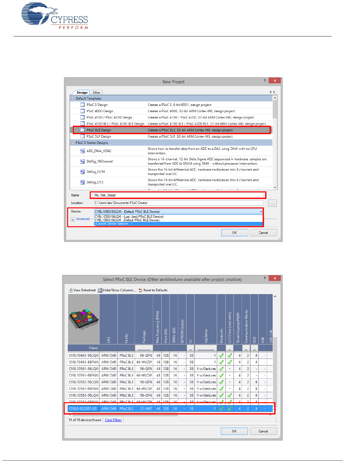
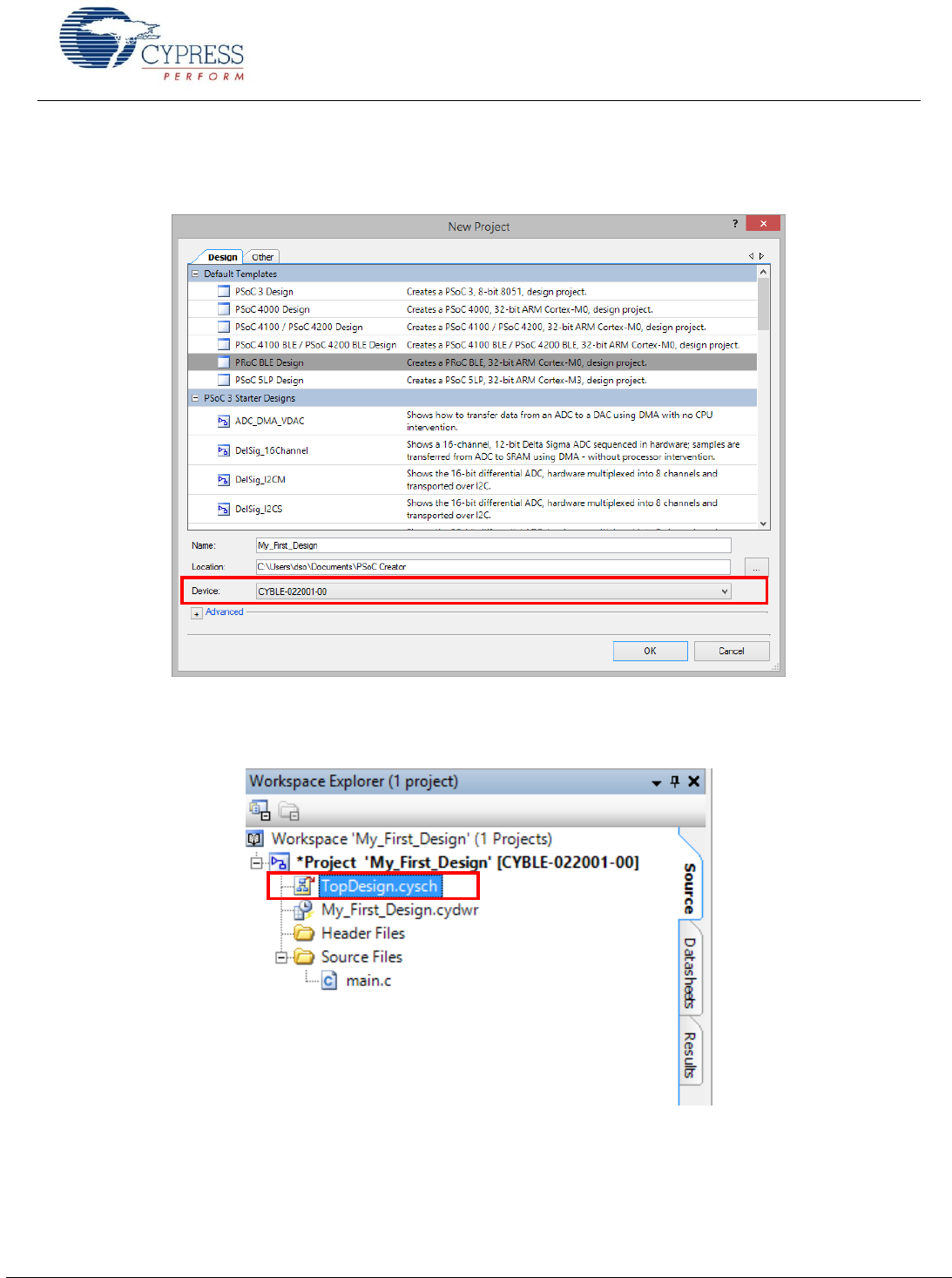
3. Choose the project template PRoC BLE Design, and give the project a name such shown in
Figure 24. Choose an appropriate location for your new project.
Figure 24. Naming the New Project and Device Selector Guide Location
4. Once in the Device Selector Guide, scroll down and locate the CYBLE-022001-00 part number (Device Selector Guide
location is shown in Figure 24).
Figure 25. Device Selector Guide
Getting Started With EZ-
www.cypress.com Document No.: 001-96841 Rev. ** 25
5. The EZ-BLE PRoC Module CYBLE-022001-00 is then selection from the Device
Selector Guide. Click OK to start the project.
Figure 26. Launching the Device Selector
6. Creating a new project generates a project folder with a baseline set of files. You can view these files in the Workspace
Explorer window, as shown in Figure 27. Open the project schematic file TopDesign.cysch by double-clicking it.
Figure 27. Opening Top Design Schematic
Getting Started With EZ-
www.cypress.com Document No.: 001-96841 Rev. ** 26
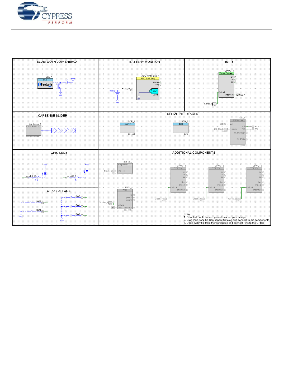
7. You can see pre-populated Components in the schematic as Figure 28 shows.
Figure 28. Pre-populated Components
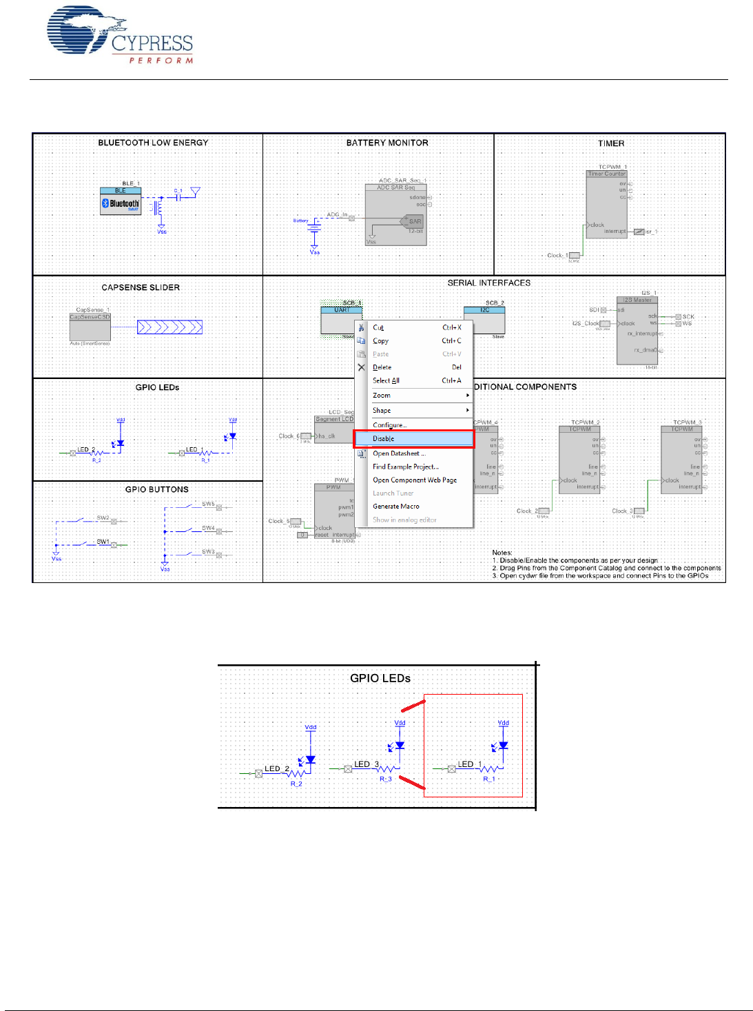
8. Disable/enable the Components per your design. For this design, right-click on each of the components as follows and
enable/disable components/features as Figure 29 shows:
Disable ADC_SAR_Seq_1 and ADC_In from the BATTERY MONITOR section
In the GPIO BUTTONS section, disable all buttons except SW1
In the TIMER section, disable TCPWM_1, Clock_1, and ISR_1
Disable Capsense_1, from TOUCH PAD section.
Disable SCB_1 and SCB_2 from the Serial Interfaces section (I2S_1 should already be disabled)
Instead of disabling, deleting the unused Components is also possible. These components have an option of bringing back
from Component Catalog if required.
Getting Started With EZ-
www.cypress.com Document No.: 001-96841 Rev. ** 27
Figure 29.Enable/Disable Components
9. After performing the actions in step 7, you will see the schematic as shown in Figure 22.
10. Add one more LED by selecting the following schematic and right-clicking Copy and Paste as shown in Figure 30.
Figure 30 Adding One More LED
11. You can configure the Bluetooth Low Energy Component with the following properties by double-clicking on the
Component as shown in Figure 31.
GAP peripheral role with Find Me Target (GATT server) configuration as shown in Figure 31
Services and characteristics for Find Me profile are shown in Figure 32 and can be left to default values
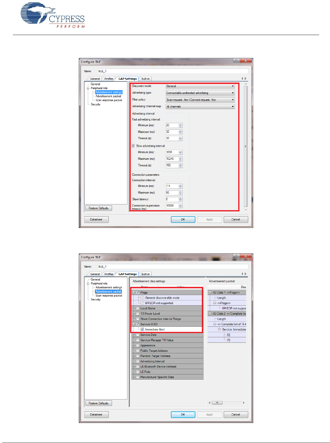
Limited advertisement mode with an advertising timeout of 30 seconds and fast advertisement interval of 20 to 30 ms
as show in Figure 33
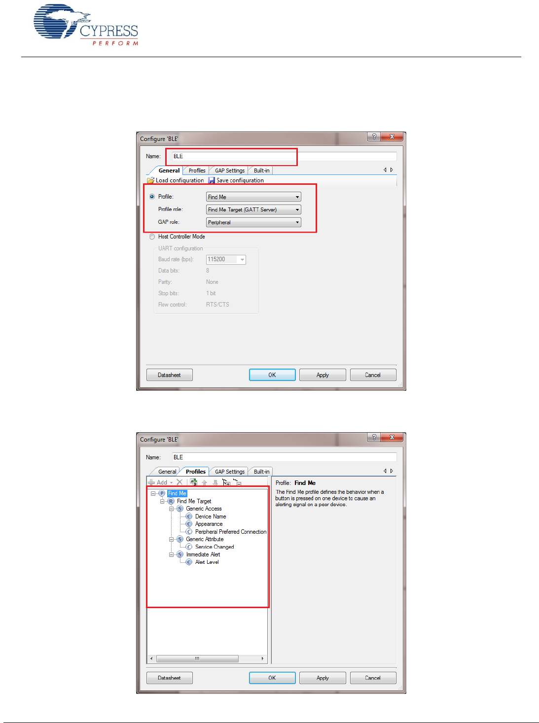
Getting Started With EZ-
www.cypress.com Document No.: 001-96841 Rev. ** 28
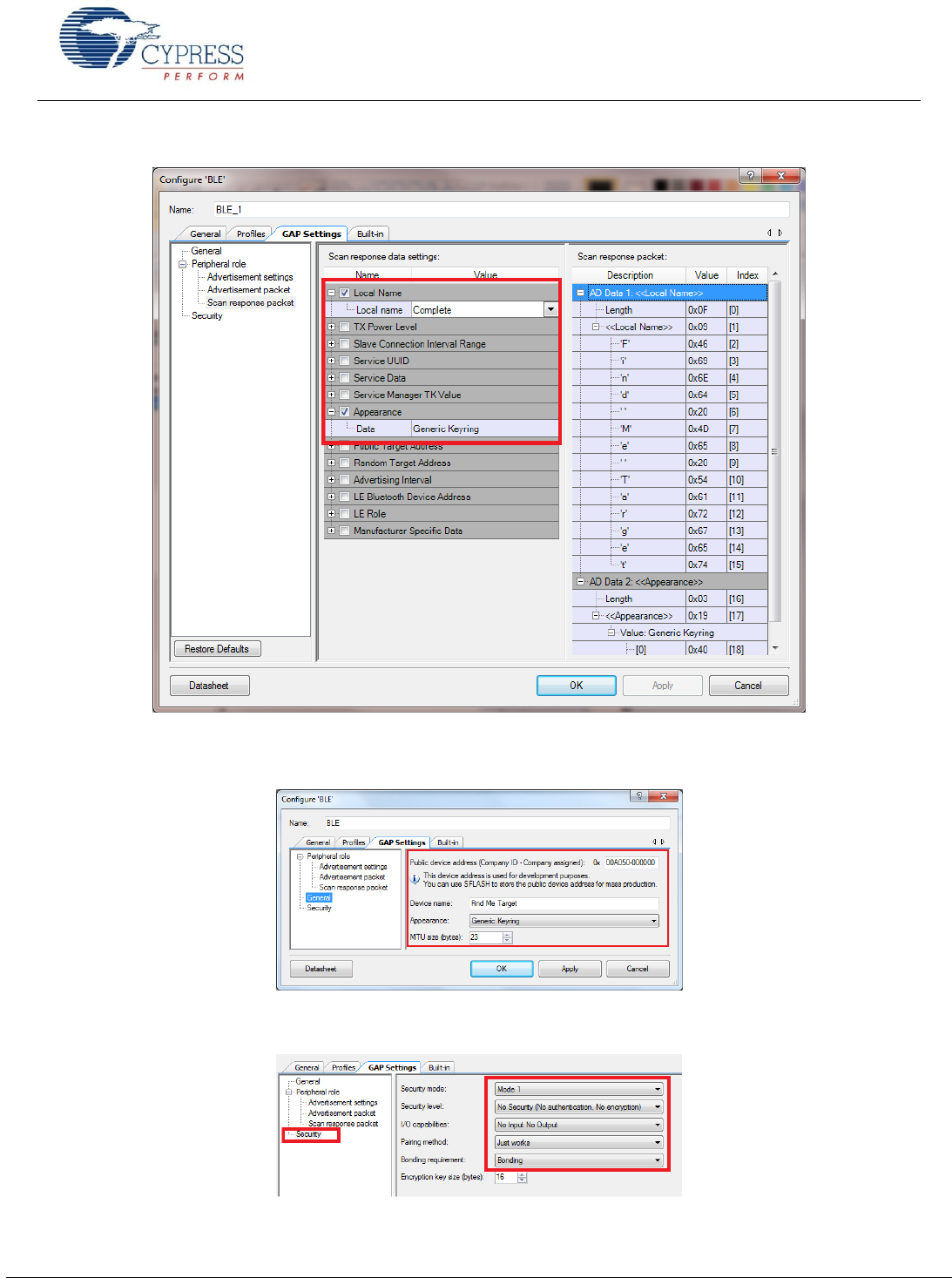
GAP Device Name set to Find Me Target and Appearance set to Generic Keyring’ as shown in Figure 36
GAP security set to least security configuration with no authentication or encryption as shown in Figure 37
Figure 31. Bluetooth Low Energy Component General Configuration
Figure 32. Bluetooth Low Energy Component Profiles Configuration
Getting Started With EZ-
www.cypress.com Document No.: 001-96841 Rev. ** 29
Figure 33. Bluetooth Low Energy Component GAP Advertisement Settings
Figure 34. Bluetooth Low Energy Component GAP Advertisement Packet
Getting Started With EZ-
www.cypress.com Document No.: 001-96841 Rev. ** 30
Figure 35. Bluetooth Low Energy Component GAP Scan Response Packet
Figure 36. Bluetooth Low Energy Component GAP General Settings
Figure 37. Bluetooth Low Energy Component GAP Security Settings
Getting Started With EZ-
www.cypress.com Document No.: 001-96841 Rev. ** 31
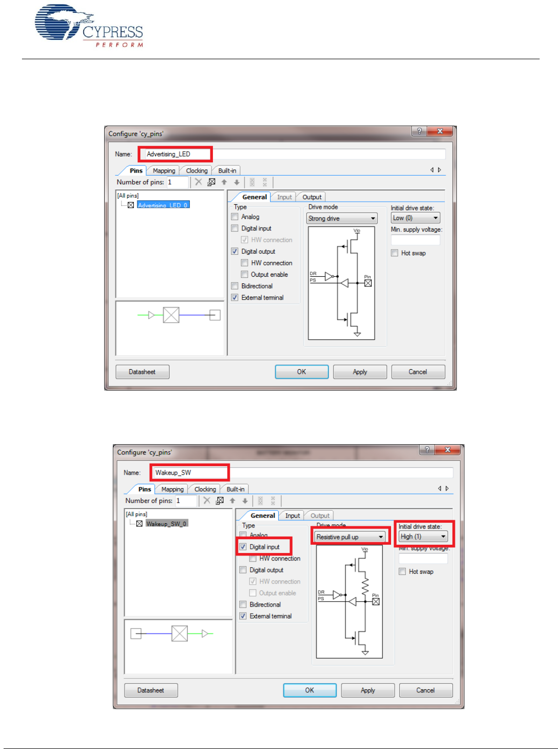
12. Double-click on LED1 and change the name to Advertising_LED for LED1 as shown in Figure 38. Similarly rename the
other two LEDs as Disconnect_LED and Alert_LED. Configure the LED as Strong drive mode.
Figure 38. Renaming a Pin Component
13. Double-click on SW1 and change the name to Wakeup_SW. Configure the pin as interrupt as shown in Figure 39 and
Figure 40.
Figure 39. Digital Input Pin Configuration
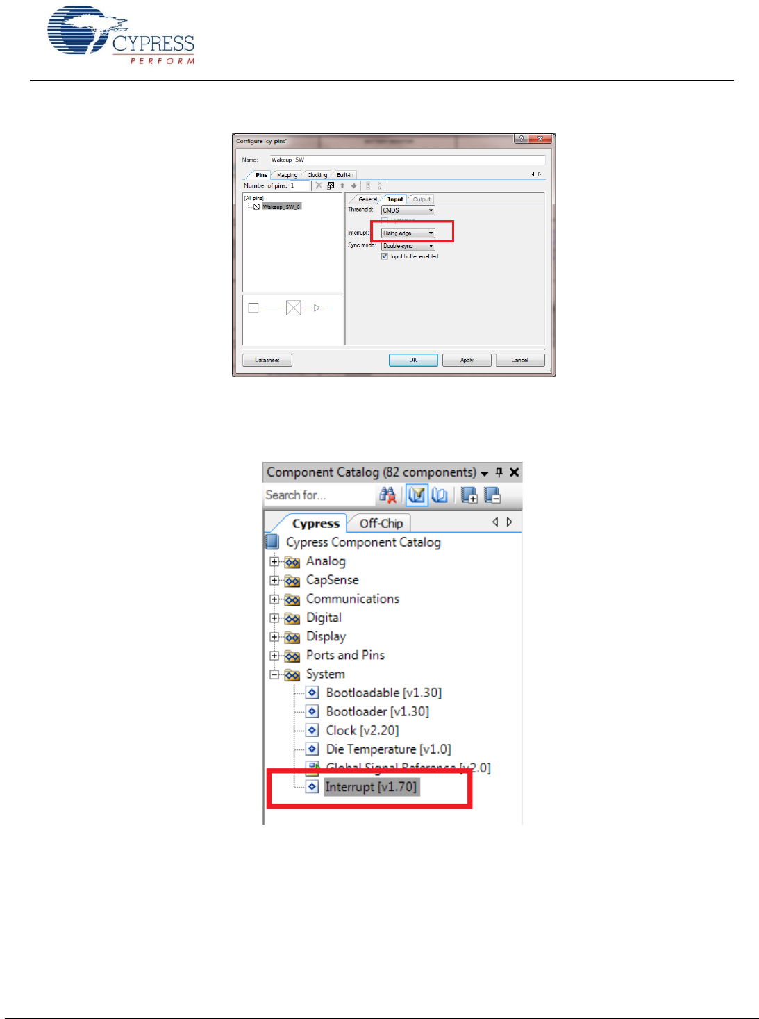
Getting Started With EZ-
www.cypress.com Document No.: 001-96841 Rev. ** 32
Figure 40. Digital Input Pin Interrupt Configuration
14. Drag and drop an Interrupt Component from the Component Catalog. Change the name to Wakeup_Interrupt and wire it
irq output as Figure 41 , Figure 42, and Figure 43 show.
Figure 41. Location of the Interrupt Component
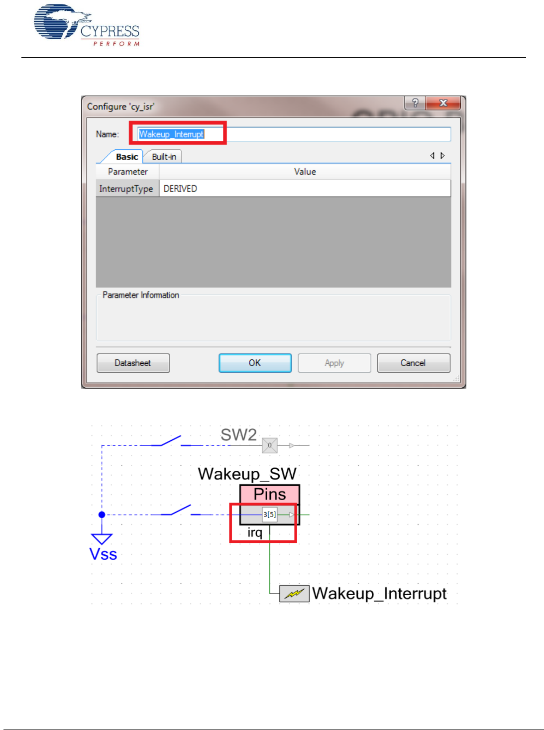
Getting Started With EZ-
www.cypress.com Document No.: 001-96841 Rev. ** 33
Figure 42. Renaming the Interrupt Component
Figure 43 Wiring the Interrupt and Pin Component
Getting Started With EZ-
www.cypress.com Document No.: 001-96841 Rev. ** 34
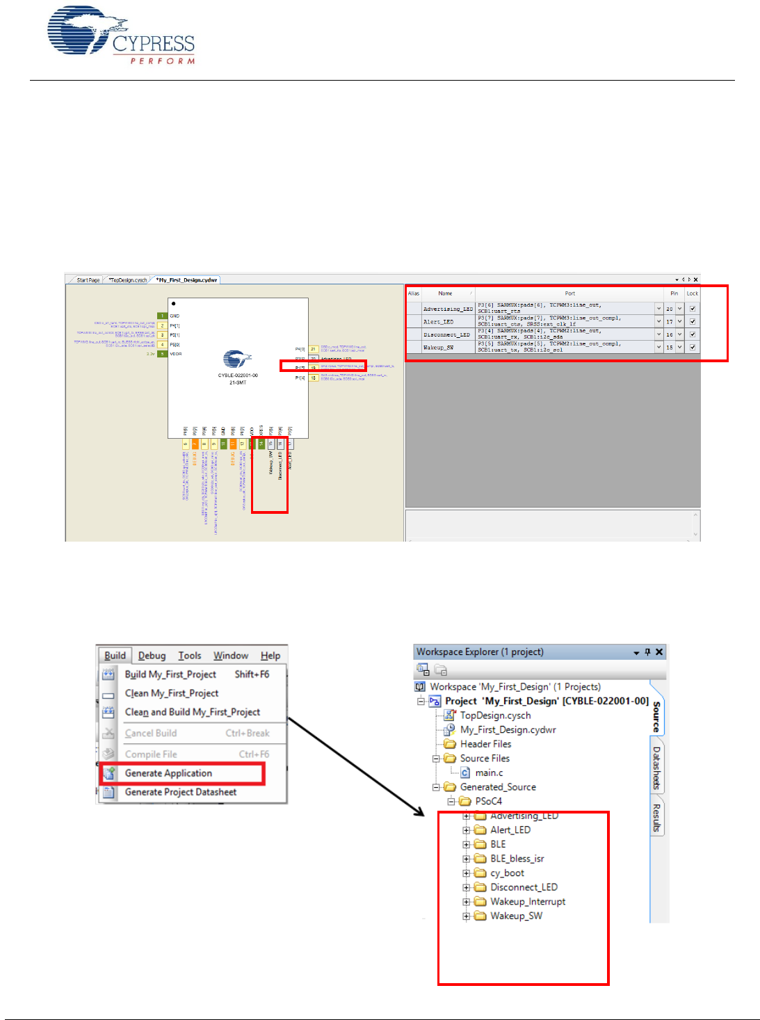
15. To assign pins to the LEDs and button, open the file My_First_Project.cydwr (Design-Wide Resource file) from
Workspace Explorer and click the Pins tab. You can use this tab to select the device pins for the outputs
(Advertising_LED, Disconnect_LED, and Alert_LED) and Wakeup_SW for input as Figure 44 shows. The following pin
assignment is made with respect to the CY8CKIT-042 BLE pioneer kit and the CYBLE-022001-EVAL board connections.
The LEDs on the CY8CKIT-042 BLE baseboard are mapped to P3[6] (green), P3[7] (blue), and P2[6] (red) on the Pioneer
kit baseboard. These baseboard connections correspond to connections P3[6] (green), P3[7] (blue), and P3[4] (red) of the
CYBLE-022001-EVAL module. The LEDs are Active low. Wakeup_SW is mapped to P2[7] of the Pioneer Kit baseboard,
which is P3[5] of the CYBLE-022001-EVAL module. Refer to CYBLE-022001-EVAL Connections to CY8CKIT-042-BLE for
details on the EZ-BLE PRoC Module Evaluation board connections.
Figure 44.Pin Selection
16. Select Generate Application from the Build menu. Notice in the Workspace Explorer window that PSoC Creator
automatically generates source code files for the Bluetooth Low Energy, Clock, and Digital Output/Input Pin Components,
as Figure 45 shows.
Figure 45. Generated Source Files
Getting Started With EZ-
www.cypress.com Document No.: 001-96841 Rev. ** 35
Write the Application Code
The main.c file in the workspace has a template for the main program function. The following main firmware blocks are
required for designing any BLE standard profile applications using PSoC Creator:
System initialization
Bluetooth Low Energy stack event handler
Bluetooth Low Energy service-specific event handler
Main loop and low power implementation
This section discusses details of these blocks with respect to the design configured in the previous section.
S ys te m I n i ti a li za t i on
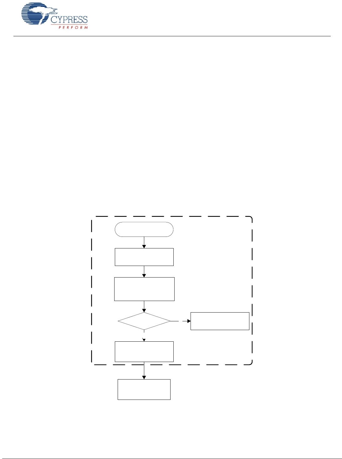
When the EZ-BLE PRoC Module is reset or wakes up from the hibernate mode, the firmware needs to perform initialization,
which includes platform initialization, enabling global interrupts, and initializing/starting the BLE Component. Figure 46 shows
the flowchart for system initialization.
As a part of the BLE Component initialization, you must pass the event handler function that will be called to receive events
from the BLE stack. The BLE stack event handler shown in Figure 49 is registered as part of the BLE initialization. If the BLE
Component initializes successfully, the firmware registers the event handler that will be called to receive IAS events and
switches control to the main loop thread.
Figure 47 shows the firmware source code for system initialization.
Figure 46. System Initialization Flowchart
Reset
Platform Initialization
- BLE Init
- Register Stack Event
Handler
BLE-Init
Success?
Register IAS Event
Handler
Y
Error HandlingN
System Initialization
Main Processing
Thread
Getting Started With EZ-
www.cypress.com Document No.: 001-96841 Rev. ** 36
Figure 47. System Initialization Firmware
BLE S ta c k E ven t Ha n dl e r
The BLE stack within the BLE Component generates a list of events to provide the BLE interface status and data to the
application firmware through the BLE stack event handler registered during the CyBle_Start API call. The event handler must
handle basic events from the stack and configure the stack with the application information to successfully establish and
maintain the BLE link. For the Find Me application that you are creating, the BLE stack event handler must process all the
events described in Table 5. The flow chart and the firmware for handling the BLE stack events are shown in Figure 48 and
Figure 49.
Table 5. Bluetooth Low Energy Stack Events
BLE Stack Event Name
Event Description
Event Handler Action
CYBLE_EVT_STACK_ON
Bluetooth Low Energy firmware stack
within the BLE Component initialized
successfully
Start Advertisement and reflect
advertisement state on the LEDs
CYBLE_EVT_GAP_DEVICE_DISCONNECTED
Bluetooth Low Energy link is
disconnected from the peer device
Start re-advertisement and reflect
advertisement state on the LEDs
CYBLE_EVT_GAP_DEVICE_CONNECTED
Bluetooth Low Energy link is
established with the peer device
Update the Bluetooth Low
Energy link state on the LEDs
CYBLE_EVT_TIMEOUT
Bluetooth Low Energy stack generic
timeout event
Configure the device in hibernate
mode if you received an
advertisement timeout event
CYBLE_API_RESULT_T apiResult;
CYBLE_STATE_T bleState;
/* Enable Global Interrupts */
CyGlobalIntEnable;
/* Start the BLE component and register a stack callback
routine */
apiResult = CyBle_Start(StackEventHandler);
if(apiResult != CYBLE_ERROR_OK)
{
/* BLE stack initialization failed, check
your configuration */
CYASSERT(0);
}
/* Register service specific callback routine for IAS */
CyBle_IasRegisterAttrCallback(IasEventHandler);

Getting Started With EZ-
www.cypress.com Document No.: 001-96841 Rev. ** 37
Figure 48. Bluetooth Low Energy Stack Event Handler Flow Chart
Stack ON or device
disconnected? Start Advertising
Device
connected?
Retrieve Connection
Handle
N
N
Y
Y
Return from stack event
handler
B LE Stack Event Handler
Advertising
timeout? Go to HibernateY
N

Getting Started With EZ-
www.cypress.com Document No.: 001-96841 Rev. ** 38
Figure 49. Bluetooth Low Energy Stack Event Handler Firmware
#define LED_ON (0u)
#define LED_OFF (1u)
extern CYBLE_GAPP_DISC_PARAM_T cyBle_discoveryParam;
extern CYBLE_GAPP_DISC_MODE_INFO_T
cyBle_discoveryModeInfo;
void StackEventHandler(uint32 event, void* eventParam)
{
switch(event)
{
case CYBLE_EVT_STACK_ON:
case CYBLE_EVT_GAP_DEVICE_DISCONNECTED:
/* Start BLE advertisement for 30 seconds and update link
* status on LEDs */
CyBle_GappStartAdvertisement();
Advertising_LED_Write(LED_ON);
Disconnect_LED_Write(LED_ON);
Alert_LED_Write(LED_OFF)
break;
case CYBLE_EVT_GAP_DEVICE_CONNECTED:
/* BLE link is established */
Advertising_LED_Write(LED_OFF);
Disconnect_LED_Write(LED_OFF);
break;
case CYBLE_EVT_TIMEOUT:
if(*(uint8 *) eventParam == CYBLE_GAP_ADV_MODE_TO)
{
/* Advertisement event timed out, go to low power
* mode (Hibernate mode) and wait for an external
* user event to wake up the device again */
Advertising_LED_Write(LED_OFF);
Disconnect_LED_Write(LED_OFF);
Alert_LED_Write(LED_OFF);
Wakeup_SW_ClearInterrupt();
Wakeup_Interrupt_ClearPending();
Wakeup_Interrupt_Start();
CySysPmHibernate();
}
break;
default:
break;
}
}
Getting Started With EZ-
www.cypress.com Document No.: 001-96841 Rev. ** 39
Blu e to o t h L ow Ene r g y Se r vi c e S p ec i f ic E v e n t Ha n dl e r
The BLE Component also generates events corresponding to each of the services supported by your design through the
service event handler that was registered in the initialization section of the code (IasEventHandler in this example). For the
Find Me application that you are creating, the BLE Component will generate Immediate Alert Service (IAS) events that will let
the application know if the Alert Level characteristic has been updated with a new value. Figure 50 and Figure 51 show the
flow chart and firmware for handling BLE IAS events.
Figure 50. Bluetooth Low Energy IAS Event Handler Flowchart
Alert Level
Updated
Y
N
Return from IAS Event
Handler
Update the global
variable
“
alertLevel”
IAS Event Handler

Getting Started With EZ-
www.cypress.com Document No.: 001-96841 Rev. ** 40
Figure 51. Bluetooth Low Energy IAS Event Handler Firmware
Ma i n Lo o p a nd L ow Pow e r O p er a ti o n
The main loop firmware in your design must periodically service the BLE stack processing event and configure the BLESS
block and the EZ-BLE PRoC Module system into the Low Power mode between connection intervals. Figure 52 and Figure 53
show the main loop flowchart and firmware.
#define NO_ALERT (0u)
#define MILD_ALERT (1u)
#define HIGH_ALERT (2u)
#define BLINK_TIMEOUT (100u)
#define LED_NO_ALERT (200u)
#define LED_MILD_ALERT (100u)
#define LED_HIGH_ALERT (0u)
uint8 alertLevel;
void IasEventHandler(uint32 event, void* eventParam)
{
/* Alert Level Characteristic write event */
if(event == CYBLE_EVT_IASS_WRITE_CHAR_CMD)
{
/* Data structure that is returned as eventParam */
CYBLE_IAS_CHAR_VALUE_T *charValue =
(CYBLE_IAS_CHAR_VALUE_T *)eventParam;
/* Extract Alert Level value from the data structure */
alertLevel = *((charValue->value->val));
}
}
Getting Started With EZ-
www.cypress.com Document No.: 001-96841 Rev. ** 41
Figure 52. Main Loop Flowchart
Figure 53. Firmware Main Loop
Process BLE Events
Device
Connected
?
Y
BLE Idle
?
Go to deep sleep mode
-
Configure wakeup pin
-
Go to Hibernate
Y
-
Execute deep sleep
wakeup sequence
-
Sleep till ECO
stabilizes
N
N
Alert Level Updated
Y
N
Process the LED status
System Normal Operation
System Low Power Operation
for(;;)
{
/* Single API call to service all the BLE stack events. Must be
* called at least once in a BLE connection interval */
CyBle_ProcessEvents();
if(CYBLE_STATE_CONNECTED == CyBle_GetState())
{
static uint8 blinkTimeout = BLINK_TIMEOUT;
/* Update Alert LED status */
switch(alertLevel)
{
case NO_ALERT:
Alert_LED_Write(LED_OFF);
break;
Getting Started With EZ-
www.cypress.com Document No.: 001-96841 Rev. ** 42
Bui l di n g a nd Gen e r at i n g H ex F i l e
Compile and Build the project by choosing Build > Build My_First_Project as shown in Figure 54.
Figure 54 Compiling the Project
case MILD_ALERT:
if(--blinkTimeout == 0)
{
Alert_LED_Write(Alert_LED_Read() ^ 0x01);
blinkTimeout = BLINK_TIMEOUT;
}
break;
case HIGH_ALERT:
Alert_LED_Write(LED_ON);
break;
default:
break;
}
bleState = CyBle_GetState();
if(bleState != CYBLE_STATE_STOPPED &&
bleState != CYBLE_STATE_INITIALIZING)
{
/* Configure BLESS in DeepSleep mode */
CyBle_EnterLPM(CYBLE_BLESS_DEEPSLEEP);
/* Configure PRoC BLE system in sleep mode */
CySysPmSleep();
/* BLE link layer timing interrupt will wake up the system */
}
}
}
}
Getting Started With EZ-
www.cypress.com Document No.: 001-96841 Rev. ** 43
Program the Device
This section shows how to program the device. If you are
using a development kit with a built-in programmer,
connect the kit board to your computer using the USB
cable. For other kits, refer to the kit user guide.
If you are developing on your own hardware, you need a
hardware debugger, for example, a Cypress CY8CKIT-
002 MiniProg3.
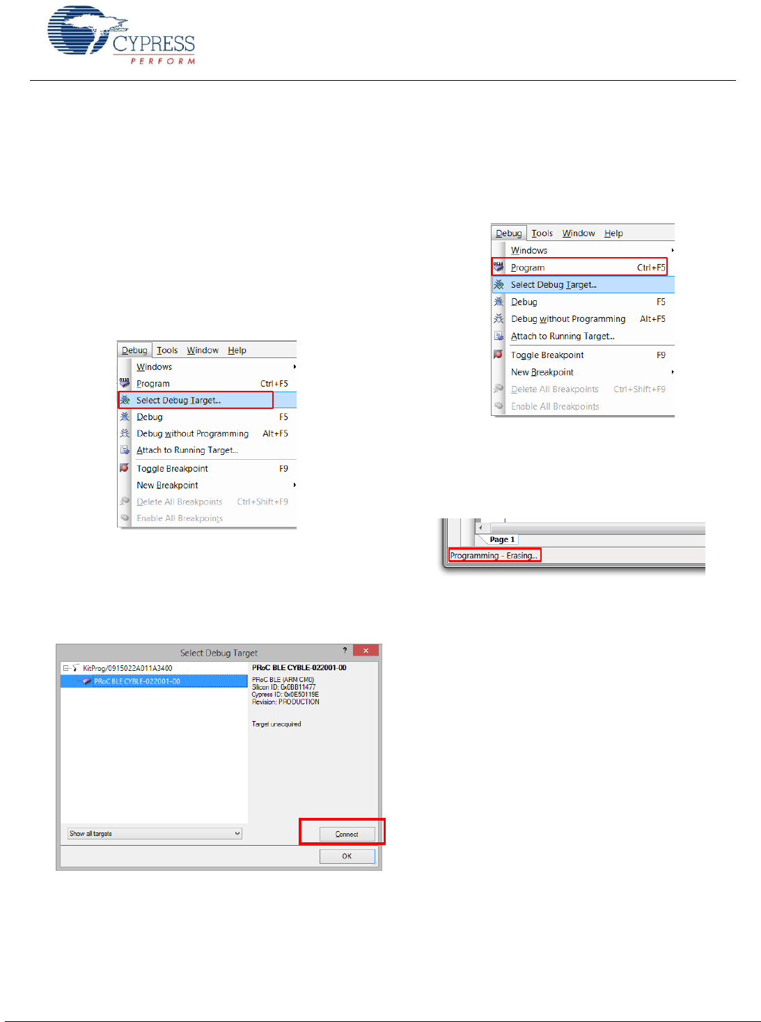
1. Select the PSoC Creator menu item Debug > Select
Debug Target, as Figure 55 shows.
Figure 55. Selecting Debug Target
2. In the Select Debug Target dialog box, click Port
Acquire, and then click Connect, as Figure 56
shows. Click OK to close the dialog box.
Figure 56. Connecting to a Device
3. Choose the Debug > Program to program the device
with the project, as Figure 57 shows.
Figure 57. Programming the Device
4. You can view the programming status on the
PSoC Creator status bar (lower-left corner of the
window), as Figure 58 shows,
Figure 58. Programming Status
Getting Started With EZ-
www.cypress.com Document No.: 001-96841 Rev. ** 44
My First EZ-BLE PRoC Module Design – Shortcut
Download the example project from AN94020 Getting Started with PRoC BLE and follow these steps to quickly generate the
example project described in the previous pages.
1. Download the AN94020.zip package from the AN94020 web page.
2. Extract the contents to a destination directory on your PC.
3. Locate My_First_Project.cywrk (PSoC Creator Workspace) and open it with PSoC Creator 3.1 SP2 or newer.
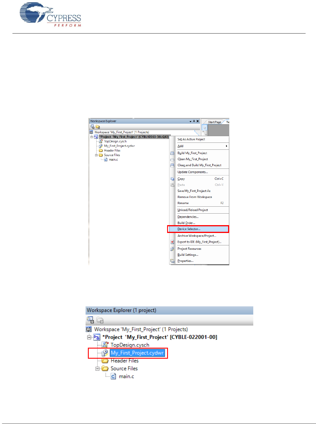
4. Right-click the project name and select Device Selector, as shown in Figure 59.
Figure 59. Device Selector Option in the Example Project
5. Locate CYBLE-022001-00 from the Device Selector, as shown in Figure 25, and select OK. You will see that the part
number associated with your project will change to display the CYBLE-022001-00 part number.
6. Double-click My_First_Project.cydwr in the Workspace Explorer, as shown in Figure 60.
Figure 60. Selecting My_First_Project.cydwr
Getting Started With EZ-
www.cypress.com Document No.: 001-96841 Rev. ** 45
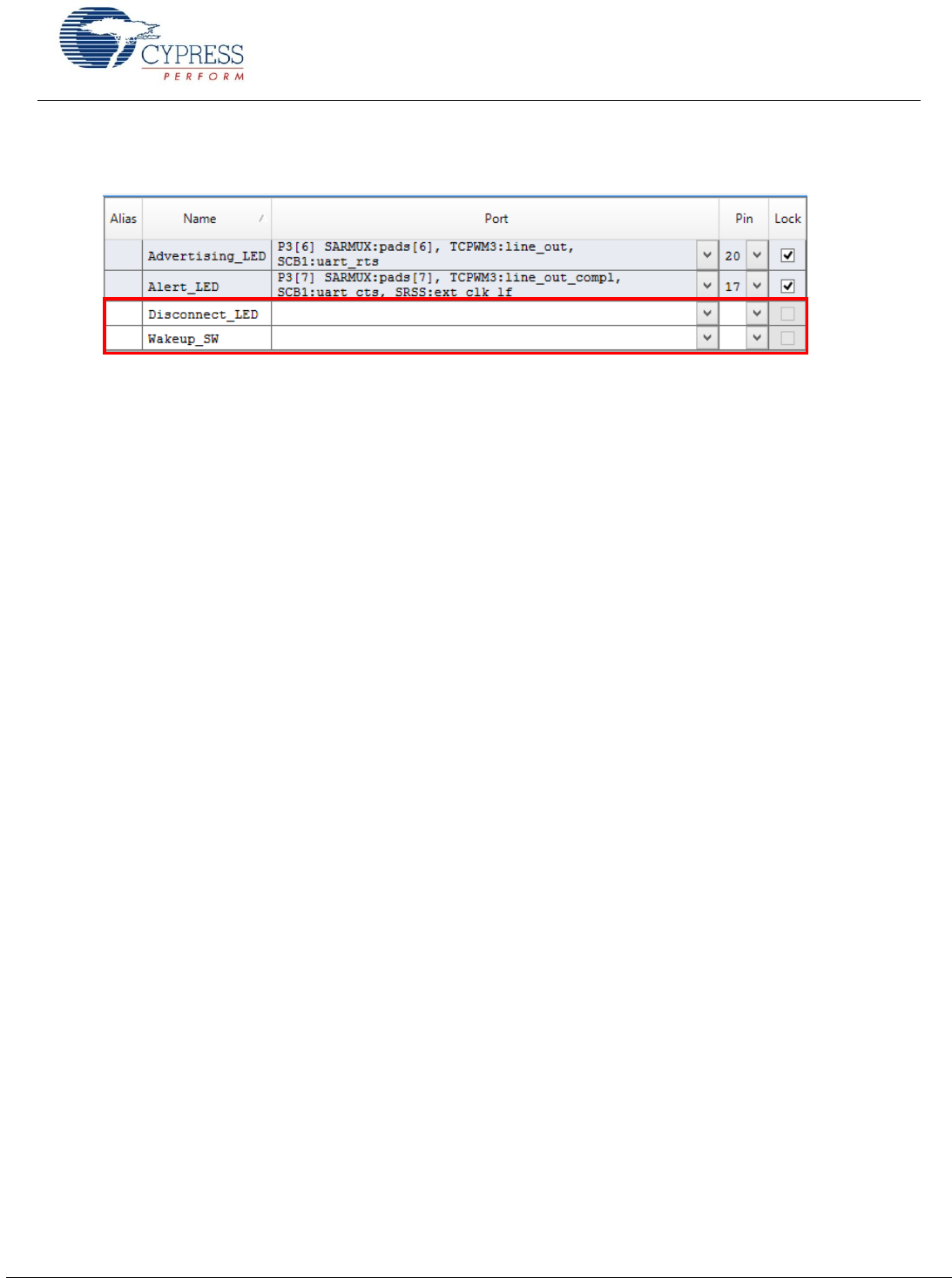
7. When the pin assignment table is displayed, you will notice that two of the connections have been unassigned. This is due
to the limited I/O supported on the EZ-BLE PRoC Module. Both Disconnect_LED and Wakeup_SW will be shown as
unassigned.
8. To complete the assignments, assign P3[4] to Disconnect_LED and P3[5] to Wakeup_SW. These connections can be
determined through checking the CY8CKIT-042-BLE and CYBLE-022001-EVAL schematics.
9. Build the application as shown in Figure 54.
10. Program the CYBLE-022001-EVAL as shown in Figure 57.
11. Proceed to the next section to test your design.
Getting Started With EZ-
www.cypress.com Document No.: 001-96841 Rev. ** 46
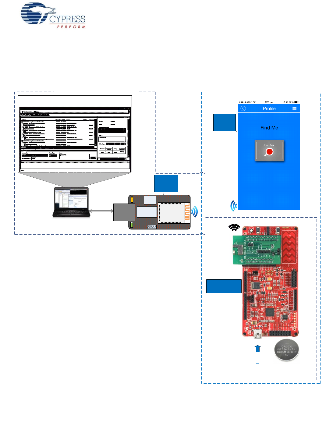
Test Your Design
This section describes how to test your BLE design using the CySmart PC application and BLE Pioneer Kit or BLE Pioneer Kit
and mobile apps. The setup for testing your design using the BLE Pioneer Kit is shown in Figure 61.
Figure 61. Pioneer Kit and CySmart Bluetooth Low Energy Setup
Usi ng t h e C yS m a r t P C a p pl i c a ti o n
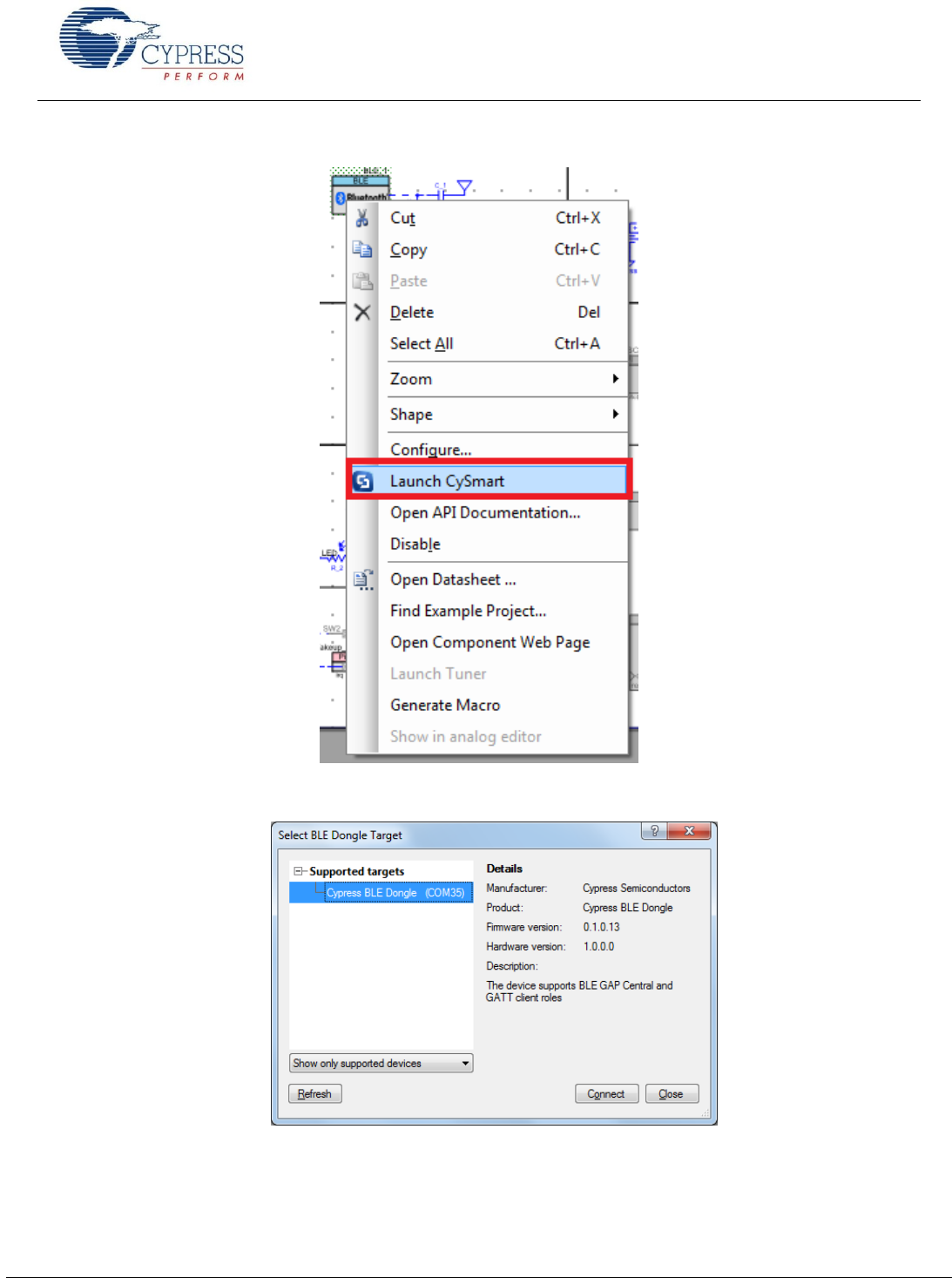
1. Connect the BLE USB dongle to your Windows machine. Wait for the driver installation to complete.
2. Launch the CySmart PC application by right-clicking on BLE Component > Launch CySmart in the project as shown in
Figure 62; it should automatically detect the BLE USB dongle. If not, click the Refresh button in the Select BLE Dongle
Target window. Click Connect as shown in Figure 63.
CySmart BLE Host Emulator
USB Program
/
Debug
(
PSoC
5
LP
)
U
S
B
Status
LED
Power
LED
3
.
3
V
LDO
PRoC
-
Smart
Module
Host PC Application
Host PC
USB
-
UART
Optionally
power through
USB
Coin cell
powered
BLE Connection with CySmart iOS
/
Android App
BLE Connection With CySmart PC App
BLE
Central
Device
BLE
Central
Device
EZ-BLE PRoC
Module Peripheral
Getting Started With EZ-
www.cypress.com Document No.: 001-96841 Rev. ** 48
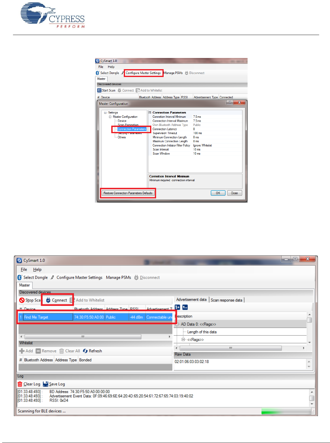
Figure 64. CySmart Master Settings Configuration
4. Press the reset or SW1 button on the BLE Pioneer Kit to start the BLE advertisements from your design.
5. In the CySmart application, click the Start Scan button. Your device (BLE Peripheral) name should appear in the
Discovered devices list.
6. Click Stop Scan and then click Connect to establish a BLE connection between the CySmart tool and your device, as
shown in Figure 65 .
Figure 65. Connect with CySmart PC Application
Getting Started With EZ-
www.cypress.com Document No.: 001-96841 Rev. ** 49
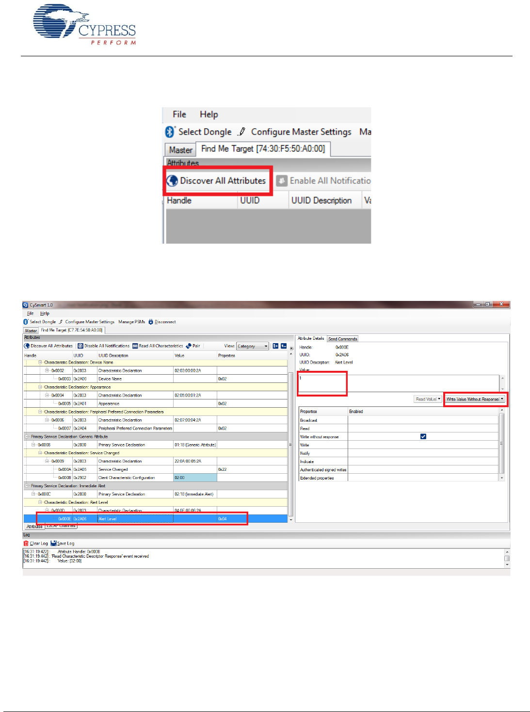
7. Once connected, discover all the attributes on your design from the CySmart application, as shown in Figure 66
Figure 66. Discover Attributes
8. Select the Alert Level characteristic and write a value of 0, 1, or 2 to Alert Level characteristic under the IAS as Figure 67
shows. Observe that the state of the LED on your device change based on your Alert Level characteristic configuration.
Figure 67. Alert Notification
Getting Started With EZ-
www.cypress.com Document No.: 001-96841 Rev. ** 50
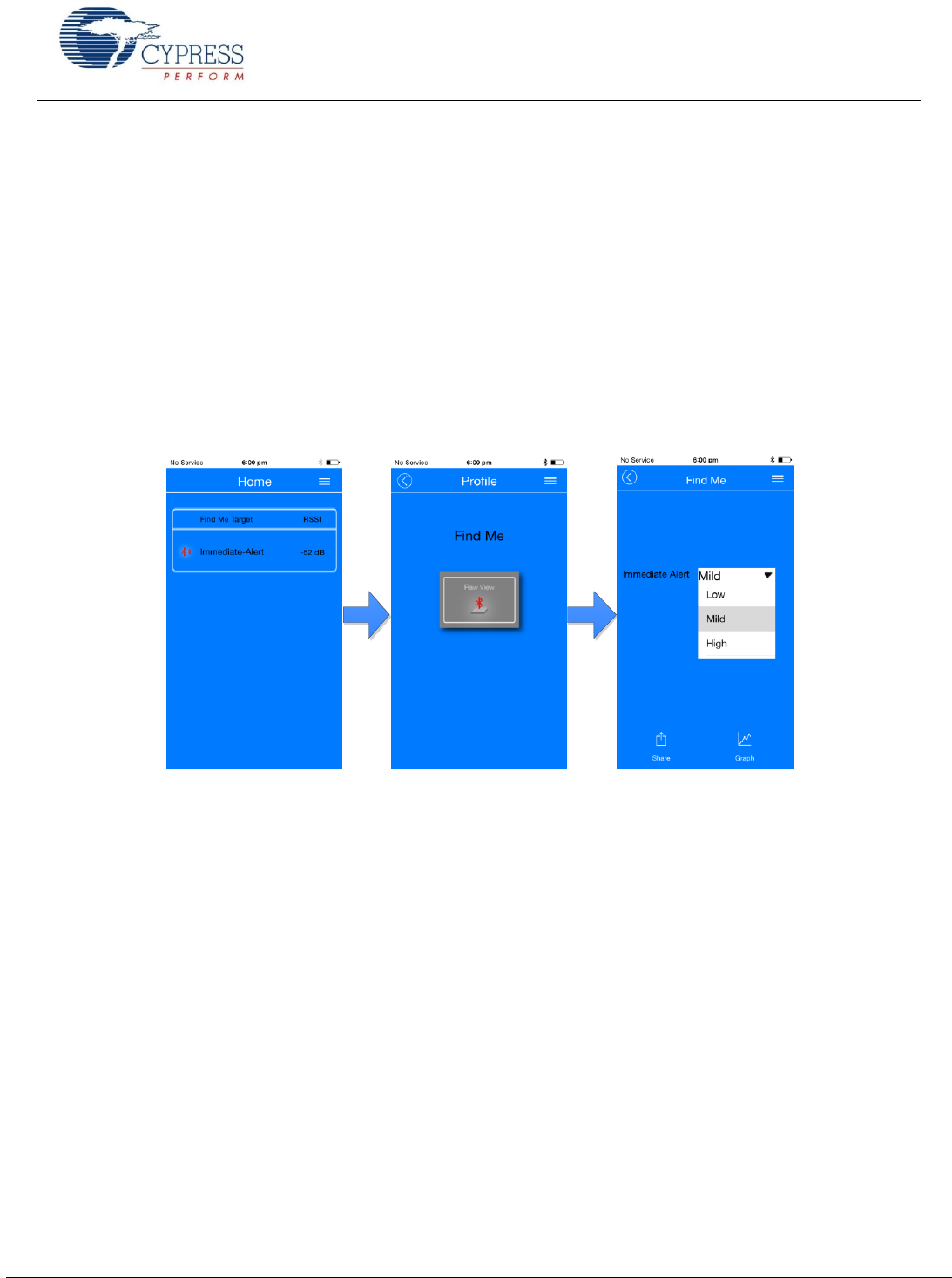
Usi ng Mo bi le A pp s
Similar to the CySmart PC application, you can use the CySmart iOS or Android app to establish a BLEconnection with your
design and perform read or write operations on different BLEservice characteristics as follows.
1. Turn ON the Bluetooth on your iOS or Android device
2. Launch the CySmart application
3. Press the reset or SW1 button on the BLE Pioneer Kit to start the BLE advertisements from your design
4. Your device will automatically appear in the CySmart app scan screen. Select your device to establish a BLE connection
5. Select the Find Me profile from the carousel view
6. Select one of the Alert Level values in the Find Me profile screen and observe the state of the LED on your device
change based on your selection.
Figure 68 shows a step-by-step configuration screenshot of the CySmart mobile app.
Figure 68. Testing with CySmart Mobile App

Getting Started With EZ-
www.cypress.com Document No.: 001-96841 Rev. ** 51
Summary
This application note explored the basics of BLE protocol
and the EZ-BLE PRoC Module solution, architecture, and
development tools. The EZ-BLE PRoC Module is a fully
integrated BLE solution that allows rapid development and
production release for customer applications. The core of
the EZ-BLE PRoC Module is the PRoC BLE chip, a
programmable embedded system-on-chip, integrating BLE
radio, configurable analog and digital peripheral functions,
memory, and an ARM Cortex-M0 microcontroller. The EZ-
BLE PRoC Module is an ideal fit for customers seeking a
qualified and certified solution in a small form-factor.
Related Application Notes
AN91445 Antenna Design Guide
AN94020 Getting Started with PRoC® BLE
AN91267 Getting Started with PSoC® 4 BLE
AN95089
Selection and Tuning Techniques
About the Author
Name:
David Solda (DSO)
Title:
Business Unit Director
Background:
David Solda has a BS in Computer
Engineering, a BS in Mathematics, and
an MBA from Santa Clara University,
California.

Getting Started With EZ-
www.cypress.com Document No.: 001-96841 Rev. ** 52
Appendix A: EZ-BLE PRoC Module Features
Table 6 summarizes the features and capabilities of the EZ-BLE PRoC Module from Cypress.
Table 6. EZ-BLE PRoC Module Features and Capabilities
Features
Device Family
CYBLE-022001-00
BLE Subsystem
BLE radio and link-layer hardware blocks with BLE 4.1- compatible protocol stack
CPU
24-MHz ARM Cortex-M0 CPU with single-cycle multiply
Flash Memory
128 KB
SRAM
16 KB
GPIOs
Up to 16
CapSense
Up to 13 sensors
CapSense Gestures
Not Supported
ADC
12-bit, 1 Msps SAR ADC with sequencer
Opamps
None
Comparators
None
Current DACs
One 7-bit, and one 8-bit
Power Supply Range
1.9 V to 5.5 V
Low-Power Modes
Deep-Sleep mode at 1.3 µA
Hibernate mode at 150 nA
Stop mode at 60 nA
Serial Communication
2 independent serial communication blocks (SCBs) with programmable I2C, SPI, UART, or I2S
Timer Counter Pulse-
Width Modulator
(TCPWM)
4
Universal Digital
Blocks (UDBs)
None
Additional Digital
Peripherals (I2S,
PWM)
None
Clocks
3-MHz to 24-MHz IMO
32-kHz ILO
Power Supply
Monitoring
Power-on reset (POR)
Brown-out detection (BOD)
Low-voltage detection (LVD)
Module Size Package
10 mm × 10 mm × 1.80 mm SMT Module
Integrated Crystal
Oscillators
24-MHz ECO integrated on module
32-kHz WCO integrated on module
Antenna Type
Chip antenna (Johanson Technology Inc. part number 2450AT18B100)

Getting Started With EZ-
www.cypress.com Document No.: 001-96841 Rev. ** 53
Appendix B: Cypress Terms of Art
This section lists the most commonly us
PSoC PSoC is a programmable, embedded design platform that includes a CPU, such as the 32-bit ARM® Cortex®-M0, with
both analog and digital programmable blocks. It accelerates embedded system design with reliable, easy-to-use solutions,
such as touch sensing and enables low-power designs.
PSoC 4 BLE A PSoC 4 IC with an integrated BLE radio that includes a royalty-free BLE protocol stack compatible with
the Bluetooth 4.1 specification.
PSoC Creator PSoC 3, PSoC 4, and PSoC 5LP Integrated Design Environment (IDE) software that installs on your PC and
allows concurrent hardware and firmware design of PSoC systems, or hardware design followed by export to other popular
IDEs.
Components Free embedded ICs represented by an icon in PSoC Creator software. These are used to integrate multiple
ICs and system interfaces into one PSoC Component that are inherently connected to the MCU via the main system bus. For
example, the BLE Component creates Bluetooth Smart products in minutes. Similarly, you can use the Programmable Analog
Components for sensors.
Component Configuration Tools Simple graphical user interfaces in PSoC Creator that embedded in each Component. It
is used to customize the Component parameters and is accessed by right-clicking a Component.
PSoC Programmer PSoC Programmer is a flexible, integrated programming application for programming PSoC devices.
PSoC Programmer is integrated with PSoC Creator to program PSoC 3, PSoC 4, PRoC, and PSoC 5LP designs.
MiniProg3 A programming hardware for development purposes that is used to program PSoC devices on your custom
board or PSoC development kits that do not support a built-in programmer.
Getting Started With EZ-
www.cypress.com Document No.: 001-96841 Rev. ** 54
Appendix C: Code Examples
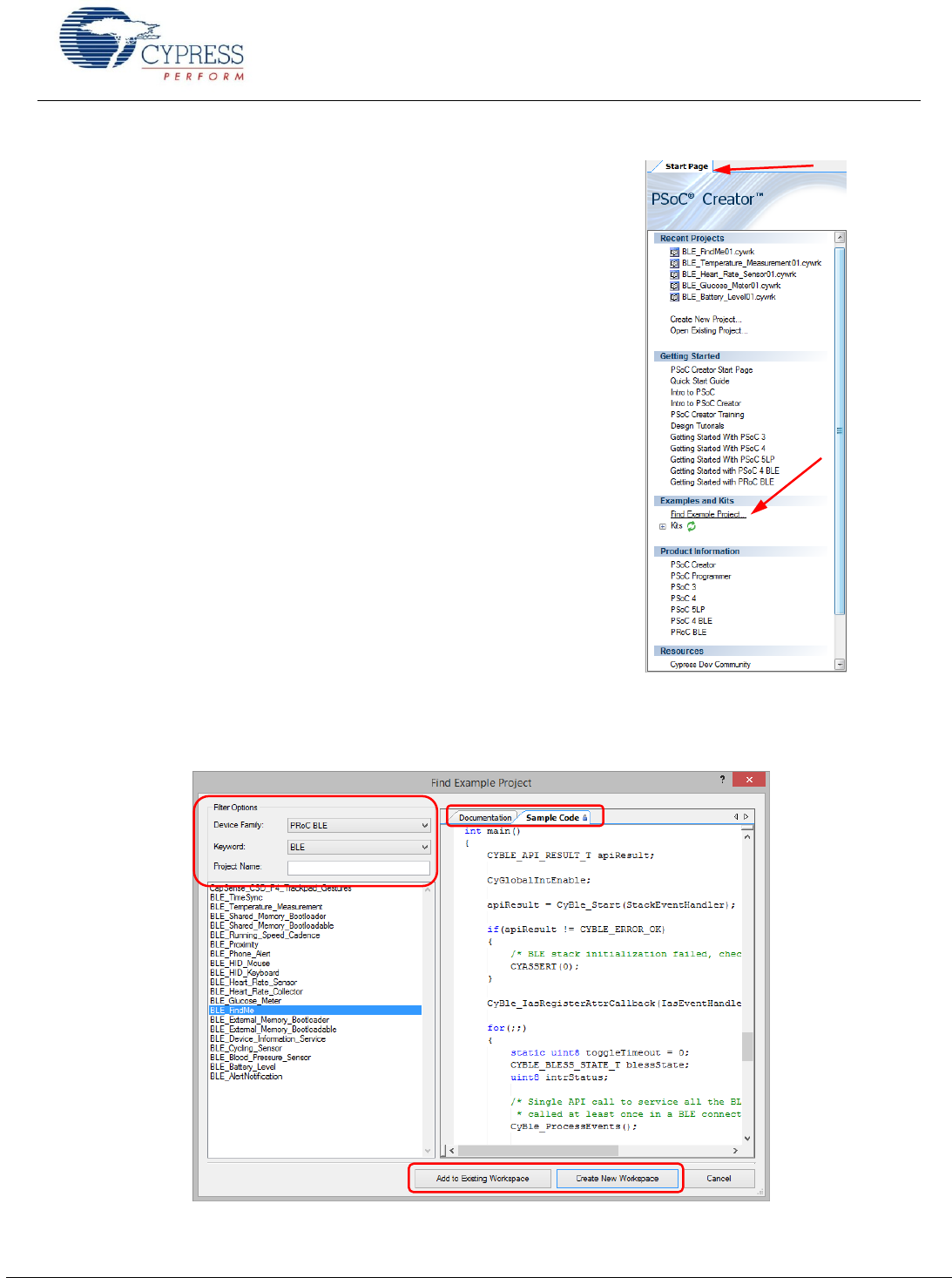
PSoC Creator includes a large number of code example projects. These
projects are available from the PSoC Creator Start Page, as Figure 69
shows.
Example projects can speed up your design process by starting you off
with a complete design, instead of a blank page. The example projects
also show how PSoC Creator Components can be used for various
applications. Code examples and datasheets are included, as Figure 70
shows.
In the Find Example Project dialog shown in Figure 70, you have several
options:
Filter for examples based on architecture or device family. For EZ-
BLE PRoC Module, use the PRoC BLE filter. Most of the PRoC BLE
example projects can reconfigure to work with the EZ-BLE PRoC
Module.
Select from the menu of examples offered based on the Filter
Options. There are more than 20 BLE example projects for you to get
started, as shown in Figure 70.
Review the datasheet for the selection (on the Documentation tab)
Review the code example for the selection. You can copy and paste
code from this window to your project, which can help speed up code
development.
Or create a new project (and a new workspace if needed) based on
the selection. This can speed up your design process by starting you
off with a complete basic design. You can then adapt that design to
your application.
Figure 69. Code Examples in PSoC Creator
Figure 70. Code Example Projects with Sample Code
Getting Started With EZ-
www.cypress.com Document No.: 001-96841 Rev. ** 55
Appendix D: Regulatory information:
FCC:
FCC NOTICE:
The device CYBLE-022001-00, including the antenna 2450AT18B100 from Johanson
technology, complies with Part 15 of the FCC Rules. The device meets the requirements for
modular transmitter approval as detailed in FCC public Notice DA00-1407.transmitter Operation
is subject to the following two conditions: (1) This device may not cause harmful interference,
and (2) This device must accept any interference received, including interference that may
cause undesired operation.
CAUTION
The FCC requires the user to be notified that any changes or modifications made to this device
that are not expressly approved by Cypress Semiconductor may void the user's authority to
operate the equipment.
This equipment has been tested and found to comply with the limits for a Class B digital device,
pursuant to Part 15 of the FCC Rules. These limits are designed to provide reasonable
protection against harmful interference in a residential installation. This equipment generates
uses and can radiate radio frequency energy and, if not installed and used in accordance with
the instructions, may cause harmful interference to radio communications. However, there is no
guarantee that interference will not occur in a particular installation. If this equipment does
cause harmful interference to radio or television reception, which can be determined by turning
the equipment off and on, the user is encouraged to try to correct the interference by one or
more of the following measures:
Reorient or relocate the receiving antenna.
Increase the separation between the equipment and receiver.
Connect the equipment into an outlet on a circuit different from that to which the receiver
is connected.
Consult the dealer or an experienced radio/TV technician for help
LABELING REQUIREMENTS
The Original Equipment Manufacturer (OEM) must ensure that FCC labelling requirements are
met. This includes a clearly visible label on the outside of the OEM enclosure specifying the
appropriate Cypress Semiconductor FCC identifier for this product as well as the FCC Notice
above. The FCC identifier is FCC ID: WAP2001.
In any case the end product must be labeled exterior with "Contains FCC ID: WAP2001"
Getting Started With EZ-
www.cypress.com Document No.: 001-96841 Rev. ** 56
ANTENNA WARNING
This device is tested with a standard SMA connector and with the antennas listed below. When
integrated in the OEMs product, these fixed antennas require installation preventing end-users
from replacing them with non-approved antennas. Any antenna not in the following table must
be tested to comply with FCC Section 15.203 for unique antenna connectors and Section
15.247 for emissions.
Table 7: Antenna used in the module
Manufacturer
Part Number
Frequency Band
Antenna Type
Gain
Johanson
Technologies
2450AT18B100
2.4 GHz
Chip
+0.5 dBi
RF EXPOSURE
To comply with FCC RF Exposure requirements, the Original Equipment Manufacturer (OEM)
must ensure to install the approved antenna in the previous.
The preceding statement must be included as a CAUTION statement in manuals, for products
operating with the approved antennas in the previous table, to alert users on FCC RF Exposure
compliance.
Any notification to the end user of installation or removal instructions about the integrated radio
module is not allowed.
The radiated output power of CYBLE-022001-00 with the chip antenna mounted (FCC ID:
WAP2001) is far below the FCC radio frequency exposure limits. Nevertheless, use CYBLE-
022001-00 in such a manner that minimizes the potential for human contact during normal
operation.
End users may not be provided with the module installation instructions. OEM integrators and
end users must be provided with transmitter operating conditions for satisfying RF exposure
compliance.
INDUSTRY CANADA CERTIFICATION
CYBLE-022001-00 is licensed to meet the regulatory requirements of Industry Canada (IC),
License: IC: 7922A-2001
Manufacturers of mobile, fixed or portable devices incorporating this module are advised to
clarify any regulatory questions and ensure compliance for SAR and/or RF exposure limits.
Users can obtain Canadian information on RF exposure and compliance from www.ic.gc.ca.
This device has been designed to operate with the antennas listed in table 7 above, having a
maximum gain of 0.5 dBi. Antennas not included in this list or having a gain greater than 0.5 dBi
are strictly prohibited for use with this device. The required antenna impedance is 50 ohms. The
Getting Started With EZ-
www.cypress.com Document No.: 001-96841 Rev. ** 57
antenna used for this transmitter must not be co-located or operating in conjunction with any
other antenna or transmitter.
IC NOTICE
The device CYBLE-022001-00 including the antenna 2450AT18B100 from Johanson
technology, complies with Canada RSS-GEN Rules. The device meets the requirements for
modular transmitter approval as detailed in RSS-GEN. Operation is subject to the following two
conditions: (1) This device may not cause harmful interference, and (2) This device must accept
any interference received, including interference that may cause undesired operation.
LABELING REQUIREMENTS
The Original Equipment Manufacturer (OEM) must ensure that IC labelling requirements are
met. This includes a clearly visible label on the outside of the OEM enclosure specifying the
appropriate Cypress Semiconductor IC identifier for this product as well as the IC Notice above.
The IC identifier is 7922A-2001. In any case, the end product must be labeled in its exterior with
"Contains IC: 7922A-2001"
EUROPEAN R&TTE DECLARATION OF CONFORMITY
Hereby, Cypress Semiconductor declares that the Bluetooth module CYBLE-022001-00 complies with
the essential requirements and other relevant provisions of Directive 1999/5/EC. As a result of the
conformity assessment procedure described in Annex III of the Directive 1999/5/EC, the end-customer
equipment should be labeled as follows:
All versions of the CYBLE-022001-00 in the specified reference design can be used in the following
countries: Austria, Belgium, Cyprus, Czech Republic, Denmark, Estonia, Finland, France, Germany,
Greece, Hungary, Ireland, Italy, Latvia, Lithuania, Luxembourg, Malta, Poland, Portugal, Slovakia,
Slovenia, Spain, Sweden, The Netherlands, the United Kingdom, Switzerland, and Norway.

Getting Started With EZ-
www.cypress.com Document No.: 001-96841 Rev. ** 58
Document History
Document Title: AN96841 Getting Started With EZ-BLE
Document Number: 001-96841
Revision
ECN
Orig. of
Change
Submission Date
Description of Change
**
4715534
DSO
04/08/2015
New application note

Getting Started With EZ-
www.cypress.com Document No.: 001-96841 Rev. ** 59
Worldwide Sales and Design Support
the office closest to you, visit us at Cypress Locations.
Products
Automotive
cypress.com/go/automotive
Clocks & Buffers
cypress.com/go/clocks
Interface
cypress.com/go/interface
Lighting & Power Control
cypress.com/go/powerpsoc
cypress.com/go/plc
Memory
cypress.com/go/memory
PSoC
cypress.com/go/psoc
Touch Sensing
cypress.com/go/touch
USB Controllers
cypress.com/go/usb
Wireless/RF
cypress.com/go/wireless
PSoC® Solutions
psoc.cypress.com/solutions
PSoC 1 | PSoC 3 | PSoC 4 | PSoC 5LP
Cypress Developer Community
Community | Forums | Blogs | Video | Training
Technical Support
cypress.com/go/support
CapSense and PSoC are registered trademarks and PSOC Creator and SmartSense are trademarks of Cypress Semiconductor Corp. All other
trademarks or registered trademarks referenced herein are the property of their respective owners.
Cypress Semiconductor
198 Champion Court
San Jose, CA 95134-1709
Phone : 408-943-2600
Fax : 408-943-4730
Website : www.cypress.com
© Cypress Semiconductor Corporation, 2015. The information contained herein is subject to change without notice. Cypress Semiconductor
Corporation assumes no responsibility for the use of any circuitry other than circuitry embodied in a Cypress product. Nor does it convey or imply any
license under patent or other rights. Cypress products are not warranted nor intended to be used for medical, life support, life saving, critical control or
safety applications, unless pursuant to an express written agreement with Cypress. Furthermore, Cypress does not authorize its products for use as
critical Components in life-support systems where a malfunction or failure may reasonably be expected to result in significant injury to the user. The
inclusion of Cypress products in life-support systems application implies that the manufacturer assumes all risk of such use and in doing so indemnifies
Cypress against all charges.
This Source Code (software and/or firmware) is owned by Cypress Semiconductor Corporation (Cypress) and is protected by and subject to worldwide
patent protection (United States and foreign), United States copyright laws and international treaty provisions. Cypress hereby grants to licensee a
personal, non-exclusive, non-transferable license to copy, use, modify, create derivative works of, and compile the Cypress Source Code and derivative
works for the sole purpose of creating custom software and or firmware in support of licensee product to be used only in conjunction with a Cypress
integrated circuit as specified in the applicable agreement. Any reproduction, modification, translation, compilation, or representation of this Source
Code except as specified above is prohibited without the express written permission of Cypress.
Disclaimer: CYPRESS MAKES NO WARRANTY OF ANY KIND, EXPRESS OR IMPLIED, WITH REGARD TO THIS MATERIAL, INCLUDING, BUT
NOT LIMITED TO, THE IMPLIED WARRANTIES OF MERCHANTABILITY AND FITNESS FOR A PARTICULAR PURPOSE. Cypress reserves the
right to make changes without further notice to the materials described herein. Cypress does not assume any liability arising out of the application or
use of any product or circuit described herein. Cypress does not authorize its products for use as critical Components in life-support systems where a
uct in a life-support systems
application implies that the manufacturer assumes all risk of such use and in doing so indemnifies Cypress against all charges.
Use may be limited by and subject to the applicable Cypress software license agreement.