Cypress Semiconductor CY5676A Bluetooth Device User Manual 3
Cypress Semiconductor Bluetooth Device 3
Contents
- 1. User manual1
- 2. User manual2
- 3. User manual3
User manual3

CY8CKIT-042-BLE-A Bluetooth® Low Energy (BLE) Pioneer Kit Guide, Doc. # 002-11468 Rev. *A 89
5. Hardware
This chapter describes the contents of the BLE Pioneer Kit hardware and its different blocks, such as
the power block, USB connection, Arduino-compatible headers, module connectors, and CapSense
slider.
The schematic and board layouts are available at the following location:
<Install_Directory>\Cypress\CY8CKIT-042-BLE-A Kit\<version>\Hardware.
5.1 BLE Pioneer Baseboard
5.1.1 PSoC 5LP
An onboard PSoC 5LP contains the KitProg, which is used to program and debug the BLE device.
The PSoC 5LP connects to the USB port of the computer through a USB Mini-B connector and to the
SWD interface of the BLE device. PSoC 5LP is a true system-level solution providing MCU, memory,
analog, and digital peripheral functions in a single chip. The CY8C58LPxx family offers a modern
method of signal acquisition, signal processing, and control with high accuracy, high bandwidth, and
high flexibility. The analog capability spans the range from thermocouples (near DC voltages) to
ultrasonic signals.
For more information, visit the PSoC 5LP web page.
See Serial Interconnection between KitProg and Module on page 105 for more details.
5.1.2 Power System
The power supply system on the BLE Pioneer Baseboard is versatile, allowing the input supply to
come from the following sources:
5-V power from the onboard USB connector
5-V to 12-V VIN power from the Arduino power header (J1)
3-V from the CR2032 coin cell
CY8CKIT-042-BLE-A Bluetooth® Low Energy (BLE) Pioneer Kit Guide, Doc. # 002-11468 Rev. *A 90
Hardware
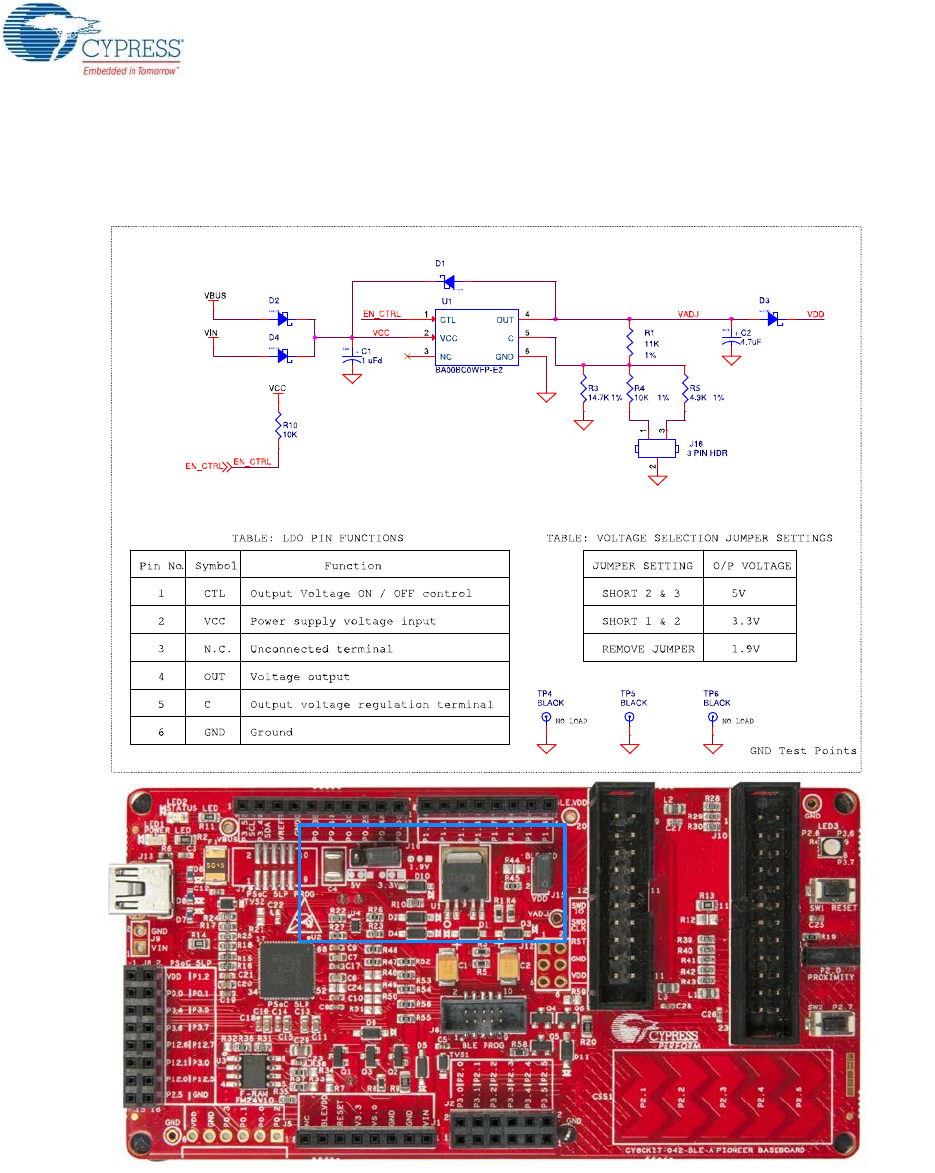
An adjustable LDO is used to output three different voltage levels (1.9 V, 3.3 V, and 5 V) to power the
module. These voltages are selected with the J16 jumper, as shown in Figure 5-1.
Figure 5-1. Schematics and Board Highlight of LDO and Power Selection Jumper
The input to the LDO can come from either the USB, the VIN pin in the Arduino header J1, or header
J9.
Note: The typical dropout voltage of the selected LDO is 0.3 V at 500-mA output current. This gives
a minimum output of 4.6 V from the input voltage of 5 V from the VBUS. This drop also considers the
voltage drop across the Schottky diode connected at the output of the LDO to protect against voltage
applied at the output terminal of the regulator. An input voltage supply over 12 V can damage the
board.
CY8CKIT-042-BLE-A Bluetooth® Low Energy (BLE) Pioneer Kit Guide, Doc. # 002-11468 Rev. *A 91
Hardware
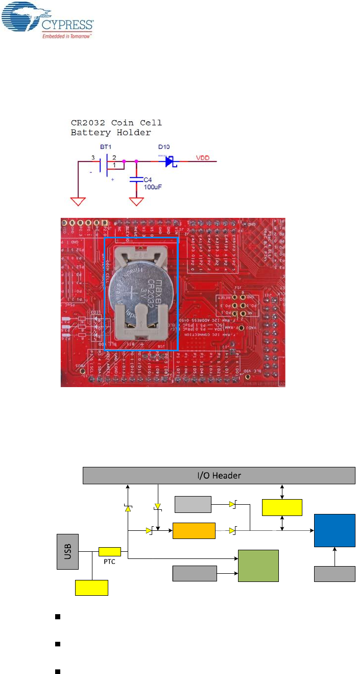
The BLE Pioneer Baseboard also contains a CR2032 coin cell holder to power it using a coin cell, as
shown in Figure 5-2.
Figure 5-2. Schematics and Board Highlight of Coin Cell Holder
5.1.2.1 Protection Circuits
The power supply rail has reverse-voltage, overvoltage, short circuits, and excess current protection
features, as shown in Figure 5-3.
Figure 5-3. Power Supply Block Diagram With Protection Circuits
A PTC resettable fuse is connected to protect the computer's USB ports from shorts and
overcurrent.
ORing diodes prevent damage to components when the BLE Pioneer Baseboard is powered
from different voltage sources at the same time.
ESD protection is provided for the USB Mini-B connector.
BLE
Module
5V Vin 3.3V
PSoC 5LP
5V
PSoC 5LP 10 Pin
Prog. Header
LDO
ESD
Protection
MOSFET based
Protection Ckt
Coin cell
Battery Holder
PSoC 4 BLE 10
Pin Prog. Header
~3V

CY8CKIT-042-BLE-A Bluetooth® Low Energy (BLE) Pioneer Kit Guide, Doc. # 002-11468 Rev. *A 92
Hardware
A MOSFET-based protection circuit is provided for overvoltage and reverse-voltage protection for
the 3.3-V rail from J1.5, as shown in Figure 5-4.
Figure 5-4. Schematics and Board Highlight of MOSFET Protection Circuit for 3.3-V Rail from J1.5
CY8CKIT-042-BLE-A Bluetooth® Low Energy (BLE) Pioneer Kit Guide, Doc. # 002-11468 Rev. *A 93
Hardware
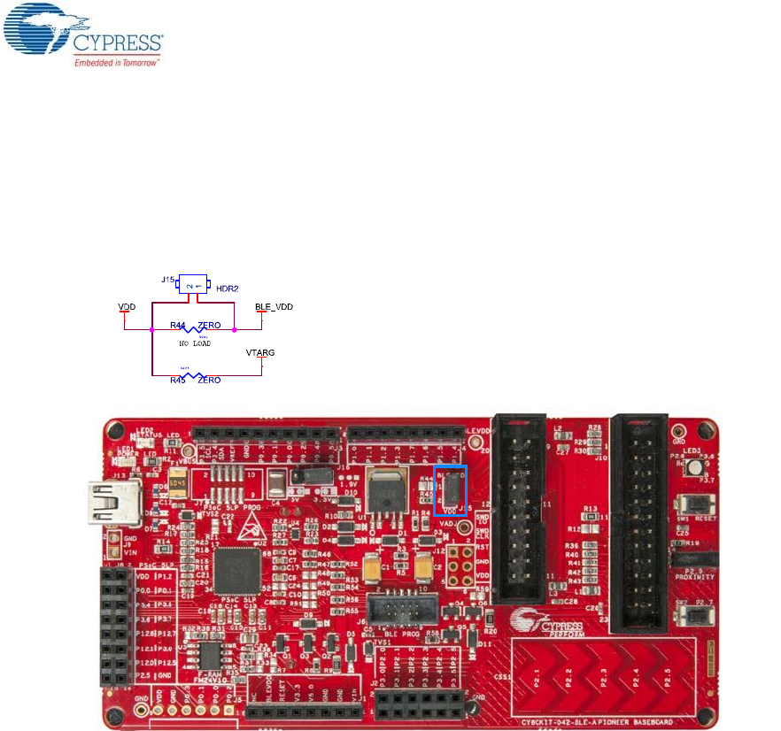
5.1.2.2 Current Measurement Jumper
To demonstrate the low power consumption of PSoC 4 BLE/PRoC BLE Module, a two-pin header
(J15) is populated in series with the power supply to the module. This can be used to measure cur-
rent using an ammeter without the need to desolder any component from the BLE Pioneer Base-
board, as shown in Figure 5-5.
Figure 5-5. Schematics and Board Highlight of Current Measurement Jumper
CY8CKIT-042-BLE-A Bluetooth® Low Energy (BLE) Pioneer Kit Guide, Doc. # 002-11468 Rev. *A 94
Hardware
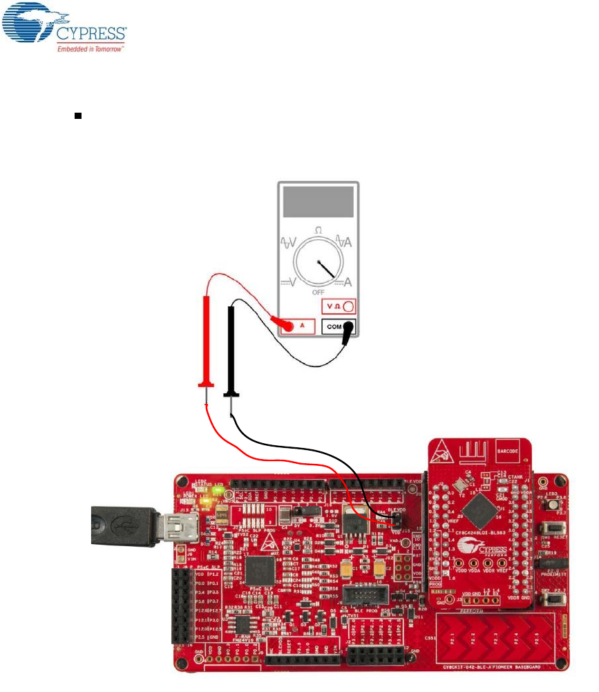
The following methods are supported for measuring the current consumption of the module.
When the BLE Pioneer Baseboard is powered through the USB port (J13), remove jumper J15
and connect an ammeter, as shown in Figure 5-6.
Figure 5-6. Current Measurement when Powered from USB Port
CY8CKIT-042-BLE-A Bluetooth® Low Energy (BLE) Pioneer Kit Guide, Doc. # 002-11468 Rev. *A 95
Hardware
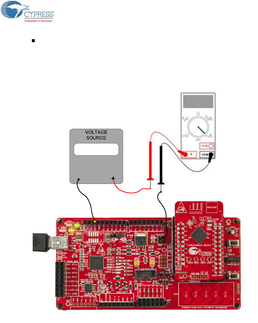
When the BLE Pioneer Baseboard is powered from an external voltage supply, remove the USB
cable from J13. Connect the positive terminal of the external voltage supply to the positive termi-
nal of the ammeter and the negative terminal of the ammeter to the upper pin of J15. Connect the
negative terminal of the external voltage supply to an onboard GND pin. Figure 5-7 shows the
required connections.
Figure 5-7. Current Measurement when Powered Separately
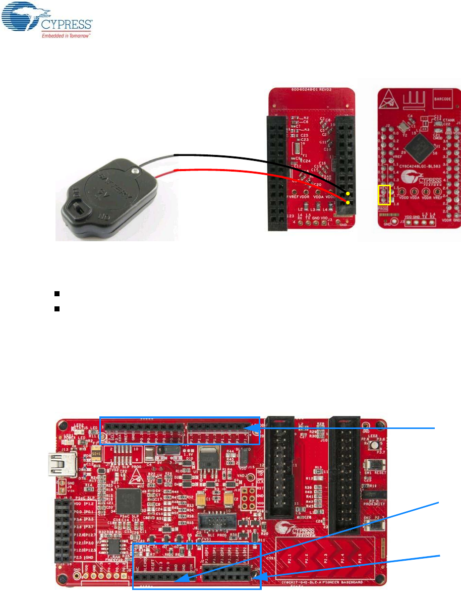
To measure the power consumption of only the module with coin cell, connect the coin cell directly to
the modules, as shown in Figure 5-8. The BLE Pioneer Baseboard is designed with additional
circuits to protect the BLE device and the F-RAM in an Arduino environment. Note that power
consumption measurements on the BLE Pioneer Baseboard will also include the power consumed
by these additional circuits.
Connect the positive terminal of the coin cell to pin J2.2 and negative terminal to pin J2.4 using
wires.
CY8CKIT-042-BLE-A Bluetooth® Low Energy (BLE) Pioneer Kit Guide, Doc. # 002-11468 Rev. *A 96
Hardware
Figure 5-8. Powering the Module using a Coin Cell
5.1.3 Programming Interface
The BLE Pioneer Kit allows you to program and debug the PSoC 4 BLE/PRoC BLE in two ways:
Using the onboard KitProg
Using a CY8CKIT-002 MiniProg3 programmer and debugger
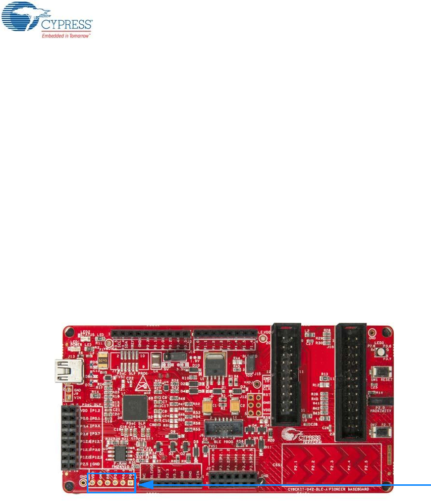
5.1.4 Expansion Connectors
5.1.4.1 Arduino-Compatible Headers (J1, J2, J3, J4, and J12-unpopulated)
The BLE Pioneer Kit has five Arduino-compatible headers: J1, J2, J3, J4, and J12, as shown in
Figure 5-9. You can develop applications based on the Arduino shield's hardware.
Figure 5-9. Arduino Headers
The J1 header contains I/O pins for reset, I/O reference voltage (IOREF), and power supply line. The
J2 header is an analog port that contains I/O pins for SAR ADC, comparator, and opamp. The J3
header is primarily a digital port that contains I/O pins for PWM, I2C, SPI, and analog reference. The
J4 header is also a digital port that contains I/O pins for UART and PWM. The J12 header is an
Arduino ICSP-compatible header for the SPI interface and is not populated. Refer to the “No Load
Components” section of Bill of Materials (BOM) on page 118 for the header part number.
Arduino
compatible
I/O header
(J3/J4)
Arduino-
compatible
I/O header
(J3/J4)
Arduino-
compatible
I/O header
(J2)
Arduino-
compatible
power
header (J1)
CY8CKIT-042-BLE-A Bluetooth® Low Energy (BLE) Pioneer Kit Guide, Doc. # 002-11468 Rev. *A 97
Hardware
Note: Take care when powering the Arduino shields via Arduino-compatible power header (J1). The
V3.3 pin will output 5 V when the board is powered from USB/VIN and the system power supply
jumper (J16) is set to 5 V operation.
Additional Functionality of Header J2
The J2 header is a 6×2 header that supports Arduino shields. The Port 2 and Port 3 pins of
PSoC 4BLE and PRoC BLE are brought to this header. The Port 2 pins also connect to the onboard
CapSense slider through 560-ohm resistors. When the CapSense feature is not used, remove these
resistors to help ensure better performance with these pins.
5.1.4.2 Pmod Connector - Digilent Pmod Compatible (J5-unpopulated)
This port supports Digilent Pmod modules (see Figure 5-10). Pmods are small I/O interfaces that
connect with the embedded control boards through either 6- or 12-pin connectors. The BLE Pioneer
Kit supports the 6-pin Pmod Type 2 (SPI) interface. For Digilent Pmod cards, go to
www.digilentinc.com.
This header is not populated on the BLE Pioneer Baseboard. You must populate this header before
connecting the Pmod daughter cards. Refer to the “No Load Components” section of Bill of Materials
(BOM) on page 118 for the header part number.
Figure 5-10. Schematics and Board Highlight of Pmod Connector
Digilent Pmod-
compatible I/O
header (J5)
CY8CKIT-042-BLE-A Bluetooth® Low Energy (BLE) Pioneer Kit Guide, Doc. # 002-11468 Rev. *A 98
Hardware
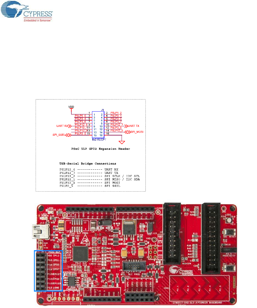
5.1.4.3 PSoC 5LP GPIO Header (J8)
An 8×2 header is provided on the BLE Pioneer Baseboard to pull out several pins of PSoC 5LP to
support advanced features such as a low-speed oscilloscope and a low-speed digital logic analyzer
(see Figure 5-11). This header also contains the USB-Serial interface pins that can be used when
these pins are not accessible on the Arduino headers because a shield is connected.
Note: You can use PSoC 5LP for your own custom firmware.
Figure 5-11. Schematics and Board Highlight of PSoC 5LP GPIO Expansion Header
CY8CKIT-042-BLE-A Bluetooth® Low Energy (BLE) Pioneer Kit Guide, Doc. # 002-11468 Rev. *A 99
Hardware
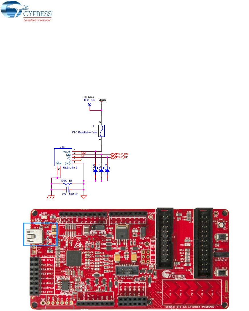
5.1.5 USB Mini-B Connector
The PSoC 5LP connects to the USB port of a computer through a Mini-B connector (see
Figure 5-12), which can also be used to power the BLE Pineer Baseboard. A resettable polyfuse is
used to protect the computer's USB ports from shorts and overcurrent. If more than 500 mA is drawn
from the USB port, the fuse will automatically break the connection until the short or overload is
removed.
Figure 5-12. Schematics and Board Highlight of USB Mini-B Connector
CY8CKIT-042-BLE-A Bluetooth® Low Energy (BLE) Pioneer Kit Guide, Doc. # 002-11468 Rev. *A 100
Hardware
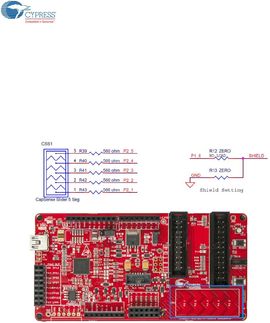
5.1.6 CapSense Circuit
5.1.6.1 CapSense Slider
The BLE Pioneer Kit has a five-segment linear capacitive touch slider, which is connected to the
PSoC 4 BLE/PRoC BLE Module pins (see Figure 5-13). The CMOD and CTANK capacitors are
required for CapSense functionality and are provided on the modules (see Module Board on
page 107). A 2.2-nF capacitor is present on the CMOD pin, P4[0], for CapSense operation. BLE
Pioneer Kit also supports CapSense designs that enable waterproofing. The connection of the shield
to the pin or to ground is made by resistors R12 and R13, respectively. By default, R13 is mounted
on the BLE Pioneer Baseboard, which connects the shield to ground. Populate R12 and remove R13
when evaluating waterproofing designs, which will connect the shield to the designated pin, P1[6].
Figure 5-13. Schematics and Board Highlight of CapSense Slider and Shield Setting
5.1.6.2 Proximity Header
The BLE Pioneer Baseboard contains a header (J14) for CapSense proximity wire connection (see
Figure 5-14).
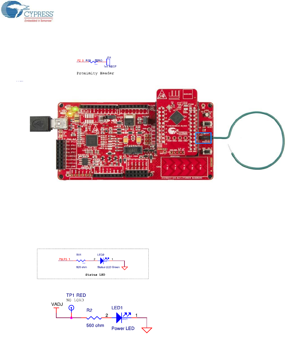
CY8CKIT-042-BLE-A Bluetooth® Low Energy (BLE) Pioneer Kit Guide, Doc. # 002-11468 Rev. *A 101
Hardware
Figure 5-14. Schematics and Board Highlight of Proximity Header
5.1.7 BLE Pioneer Baseboard LEDs
The BLE Pioneer Baseboard has three LEDs. A green LED (LED2) indicates the status of the pro-
grammer. An amber LED (LED1) indicates the status of power supplied to the board. The BLE Pio-
neer Kit also has a general-purpose tricolor LED (LED3) for user applications. These are connected
to P2_6 (red LED), P3_6 (green LED) and P3_7 (blue LED). Figure 5-15 and Figure 5-16 show the
schematics of these LEDs.
Figure 5-15. Schematics of Status and Power LED
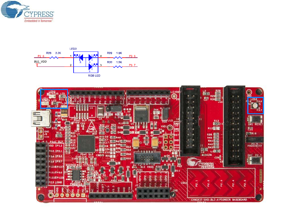
CY8CKIT-042-BLE-A Bluetooth® Low Energy (BLE) Pioneer Kit Guide, Doc. # 002-11468 Rev. *A 102
Hardware
Figure 5-16. Schematics and Board Highlight of RGB LED
CY8CKIT-042-BLE-A Bluetooth® Low Energy (BLE) Pioneer Kit Guide, Doc. # 002-11468 Rev. *A 103
Hardware
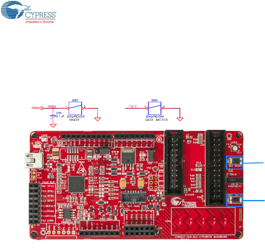
5.1.8 Push-Buttons
The BLE Pioneer Baseboard contains a reset push-button and a user push-button, as shown in
Figure 5-17. The reset button is connected to the XRES pin of BLE device and is used to reset it.
The user button is connected to P2[7] of the BLE device. Both the buttons connect to ground on acti-
vation (active low).
Figure 5-17. Schematics and Board Highlight of Reset Button and User Button
RESET (SW1)
User Button
(SW2)
CY8CKIT-042-BLE-A Bluetooth® Low Energy (BLE) Pioneer Kit Guide, Doc. # 002-11468 Rev. *A 104
Hardware
5.1.9 Cypress Ferroelectric RAM (F-RAM)
The BLE Pioneer Baseboard contains the FM24V10-G F-RAM device (see Figure 5-18), which can
be accessed through I2C lines P5[0] and P5[1] of the PSoC 4 BLE/PRoC BLE Module. The F-RAM is
1-Mbit (128KB) with an I2C speed up to 1 Mbps. The I2C slave address of the F-RAM device is
seven bits wide, and the LSB two bits are configurable through physical pins and are hardwired to 00
on the board. By default, the address of the F-RAM device used on the BLE Pioneer Baseboard is
0x50. This address can be modified by changing the R32/R36 and R33/R37 pairs. The operating
voltage range of the F-RAM is between 2 V and 3.6 V. To prevent the application of 5 V from the
adjustable LDO regulator on the BLE Pioneer Baseboard, a MOSFET-based protection circuit similar
to the one used for the 3.3-V rail is connected between the output of the regulator and the VDD pin
of the F-RAM. The protection circuit cuts off the power to the F-RAM when the output of the regulator
is greater than 3.6 V.
Figure 5-18. Schematics and Board Highlight of F-RAM
CY8CKIT-042-BLE-A Bluetooth® Low Energy (BLE) Pioneer Kit Guide, Doc. # 002-11468 Rev. *A 105
Hardware
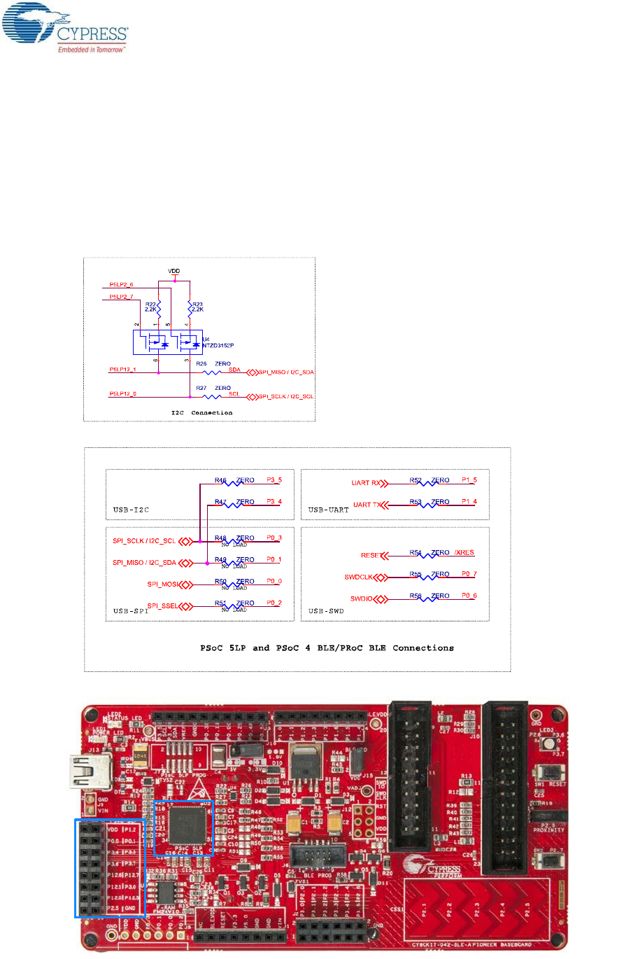
5.1.10 Serial Interconnection between KitProg and Module
The KitProg is also a USB-Serial interface. It supports USB-UART and USB-I2C bridges (see
Figure 5-19). The pull-up resistors on the I2C bus are enabled when the protocol is selected from the
user interface (such as Bridge Control Panel). The USB-Serial pins of the KitProg are also available
on the Arduino header; therefore, it can be used to control Arduino shields with the SPI/I2C/UART
interface. Refer USB-UART Bridge on page 34 and USB-I2C Bridge on page 35 for more information
on how to use these serial interconnections.
Figure 5-19. Schematics and Board Highlight of Serial Interface and I2C Pull-Up via FET
CY8CKIT-042-BLE-A Bluetooth® Low Energy (BLE) Pioneer Kit Guide, Doc. # 002-11468 Rev. *A 106
Hardware
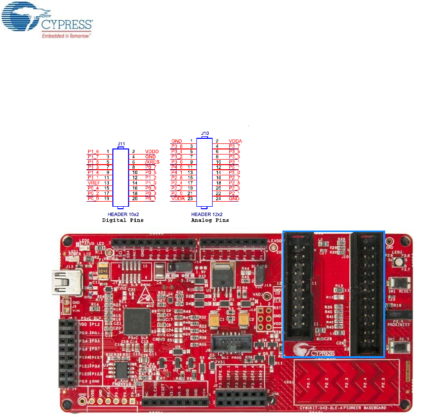
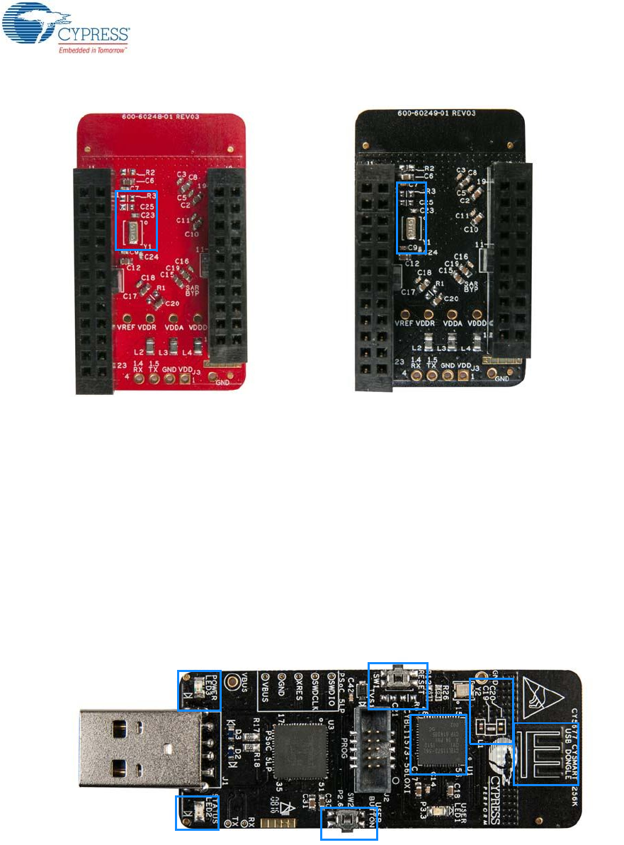
5.1.11 Module Headers
The PSoC 4 BLE and PRoC BLE Modules are connected to the BLE Pioneer Baseboard using the
two (24-pin and 20-pin) module headers, as shown in Figure 5-20.
Figure 5-20. Schematics and Board Highlight of Module Headers
For information on how to add these on your own board, refer to Adding BLE Module-Compatible
Headers on Your Baseboard on page 128.
CY8CKIT-042-BLE-A Bluetooth® Low Energy (BLE) Pioneer Kit Guide, Doc. # 002-11468 Rev. *A 107
Hardware
5.2 Module Board
5.2.1 PSoC 4 BLE or PRoC BLE Device
The PRoC BLE or PSoC 4 BLE device is the main component on the module. It provides the RF
interface and analog and digital capability. The PRoC BLE or PSoC 4 BLE pins are mapped to the
module headers (see Figure 5-21). For more information, refer to the BLE web page.
See BLE Modules and BLE Dongles Compatible with the BLE Pioneer Kit on page 130 for details.
Figure 5-21. Schematics and Board Highlight of Module Headers for BLE Pins
CY8CKIT-042-BLE-A Bluetooth® Low Energy (BLE) Pioneer Kit Guide, Doc. # 002-11468 Rev. *A 108
Hardware
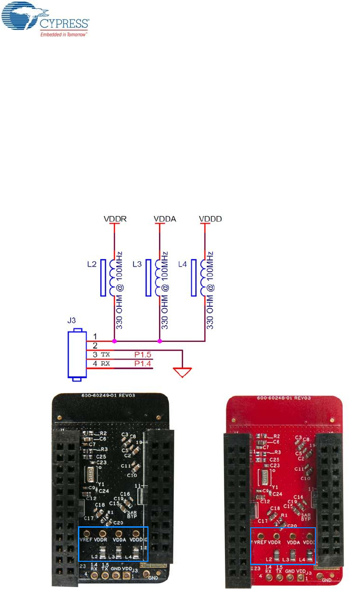
5.2.2 Module Power Connections
The module has three power domains: VDDD, VDDA, and VDDR. The VDDD connection supplies
power for digital device operation, VDDA supplies power for analog device operation, and VDDR
connection supplies power for the device radio. By default, these domains are shorted using a
330-ohm, 100-MHz ferrite bead. The domains are shorted for standalone usage scenarios of mod-
ule, such as programming the module using MiniProg 3 or using the module as a standalone data
acquisition unit.
It is recommended to place the ferrite bead between the supply to avoid ripple between VDDR and
the other two domains. If the supply ripple is less that 100 mV, these can be changed to a zero-ohm
resistor.
Figure 5-22. Schematics and Board Highlight of Ferrite Bead and Power Pin
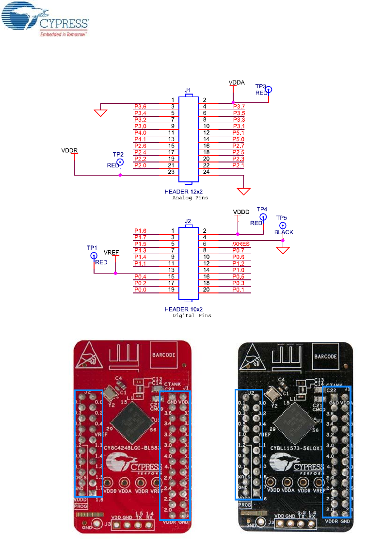
5.2.3 Module Headers (20-Pin and 24-Pin Headers)
The PSoC 4 BLE and PRoC BLE Modules connect to the BLE Pioneer Baseboard using two (20-pin
and 24-pin) module headers (Figure 5-23). All GPIOs and power domains are brought out to these
headers. These headers are the counterparts of the connectors in Expansion Connectors on
page 96.
CY8CKIT-042-BLE-A Bluetooth® Low Energy (BLE) Pioneer Kit Guide, Doc. # 002-11468 Rev. *A 109
Hardware
Figure 5-23. Schematics and Board Highlight of Headers
CY8CKIT-042-BLE-A Bluetooth® Low Energy (BLE) Pioneer Kit Guide, Doc. # 002-11468 Rev. *A 110
Hardware
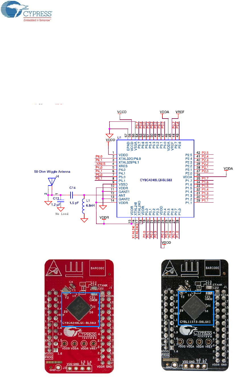
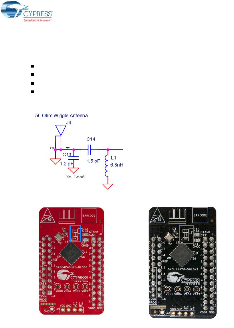
5.2.4 Wiggle Antenna
Both the modules use the wiggle antenna. Refer to the Antenna Design Guide (AN91445) for details.
Figure 5-24. Board Highlight of Wiggle Antenna
CY8CKIT-042-BLE-A Bluetooth® Low Energy (BLE) Pioneer Kit Guide, Doc. # 002-11468 Rev. *A 111
Hardware
5.2.5 Antenna Matching Network
An Antenna Matching Network is required between the BLE device and the antenna to achieve opti-
mum performance (Figure 5-25). The matching network has four main tasks:
Transform the balanced output of the radio to an unbalanced connection to the antenna (balun).
Transform the output impedance of the radio to a 50-ohm antenna.
Suppress harmonics to a level below the regulations level in TX mode.
Suppress the local oscillator (LO) leakage in RX mode.
Figure 5-25. Schematics and Board Highlight of Antenna Matching Network and Antenna
CY8CKIT-042-BLE-A Bluetooth® Low Energy (BLE) Pioneer Kit Guide, Doc. # 002-11468 Rev. *A 112
Hardware
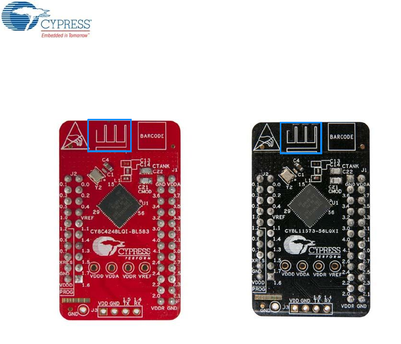
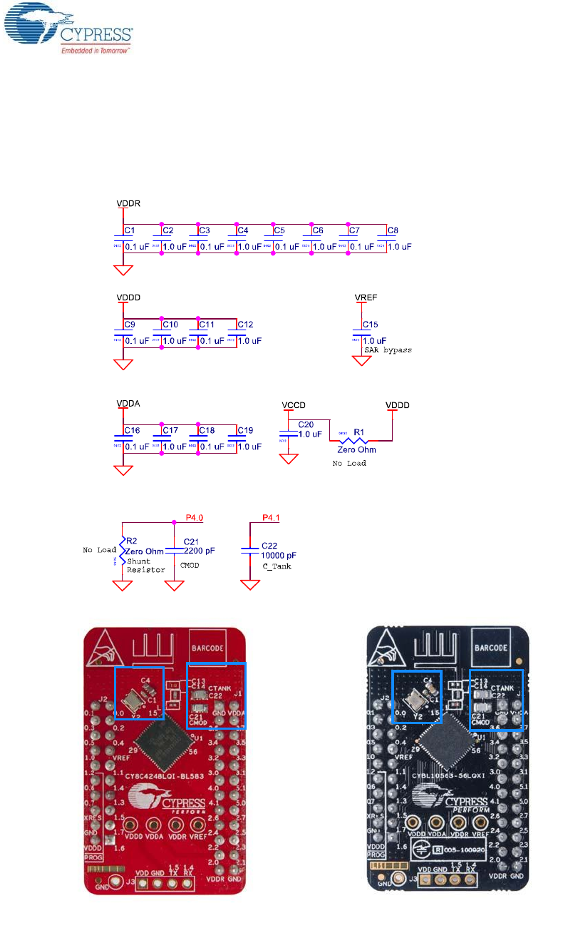
5.2.6 BLE Passives
Module boards include a 24-MHz crystal and a 32-kHz crystal, the CMOD and shield (CTANK) circuit
for CapSense, a SAR bypass capacitor, and adequate decoupling capacitors for all the power
domains, as shown in Figure 5-26.
Figure 5-26. Schematics and Board Highlight – External Crystal, CMOD, CTANK, Decaps, Jumpers
CY8CKIT-042-BLE-A Bluetooth® Low Energy (BLE) Pioneer Kit Guide, Doc. # 002-11468 Rev. *A 113
Hardware
5.2.7 Test Points
All power domains are brought out as test points for easy probing.
5.3 BLE Dongle Board
See PSoC 4 BLE or PRoC BLE Device on page 107 for schematics of PRoC BLE pins.
See Wiggle Antenna on page 110 for schematics of wiggle antenna.
See Antenna Matching Network on page 111 for schematics of antenna matching network.
See BLE Pioneer Baseboard LEDs on page 101 for schematics of power and status LED.
See Push-Buttons on page 103 for schematics of push-buttons.
Figure 5-27. Board Highlight
CY8CKIT-042-BLE-A Bluetooth® Low Energy (BLE) Pioneer Kit Guide, Doc. # 002-11468 Rev. *A 114
Hardware
5.3.1 Power System
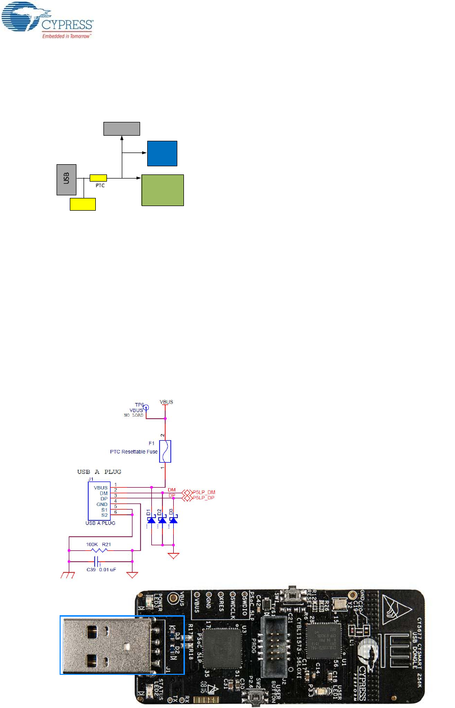
The BLE Dongle is powered directly using 5 V from the USB port, as shown in Figure 5-28.
Figure 5-28. Power Supply Block Diagram With Protection Circuits
5.3.1.1 Protection Circuits
The PTC resettable fuse is connected to protect the computer's USB ports from shorts and overcur-
rent.
5.3.2 USB Type-A Plug
The KitProg on the BLE Dongle connects to the USB port of a computer through a USB Type-A plug
(Figure 5-29). The BLE Dongle is powered using the same plug. A resettable polyfuse is used to pro-
tect the computer's USB ports from shorts and overcurrent. If more than 500 mA is applied to the
USB port, the fuse will automatically break the connection until the short or overload is removed. The
VBUS, D+, and D– lines from the USB connector are also protected against ESD events using TVS
diodes.
Figure 5-29. Schematics and Board Highlight of USB Type-A Plug
USB
5V
E S D
P r o te c tio n
PRoC
PSoC5LP
5V
5V
Headers
CY8CKIT-042-BLE-A Bluetooth® Low Energy (BLE) Pioneer Kit Guide, Doc. # 002-11468 Rev. *A 115
Hardware
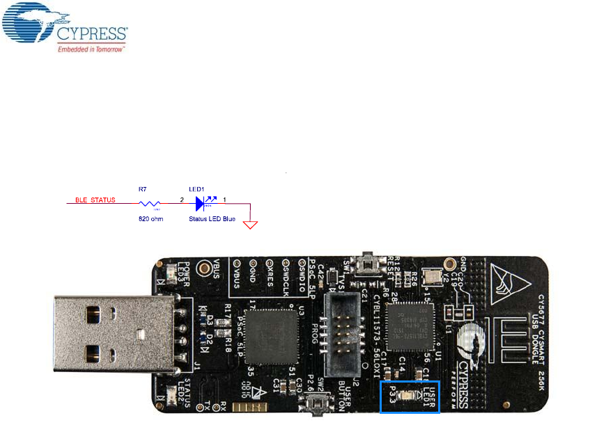
5.3.3 User LED
A user LED is provided to indicate status from the PRoC BLE device (Figure 5-30). It is also used to
show the bind status.
Figure 5-30. Schematics and Board Highlight of User LED
CY8CKIT-042-BLE-A Bluetooth® Low Energy (BLE) Pioneer Kit Guide, Doc. # 002-11468 Rev. *A 116
6. Advanced Topics
This chapter describes the functionality of the FM24V10 F-RAM in the BLE Pioneer Kit.
6.1 Using FM24V10 F-RAM
The BLE Pioneer Baseboard has an onboard ferroelectric RAM chip that can hold up to 1 Mb of
data. The chip provides an I2C communication interface for data access. It is hardwired to the I2C
lines (P5_0 and P5_1). Because the F-RAM device is an I2C slave, it can be accessed or shared
among various I2C masters on the same line. For more details on the F-RAM device, refer to the
device datasheet.
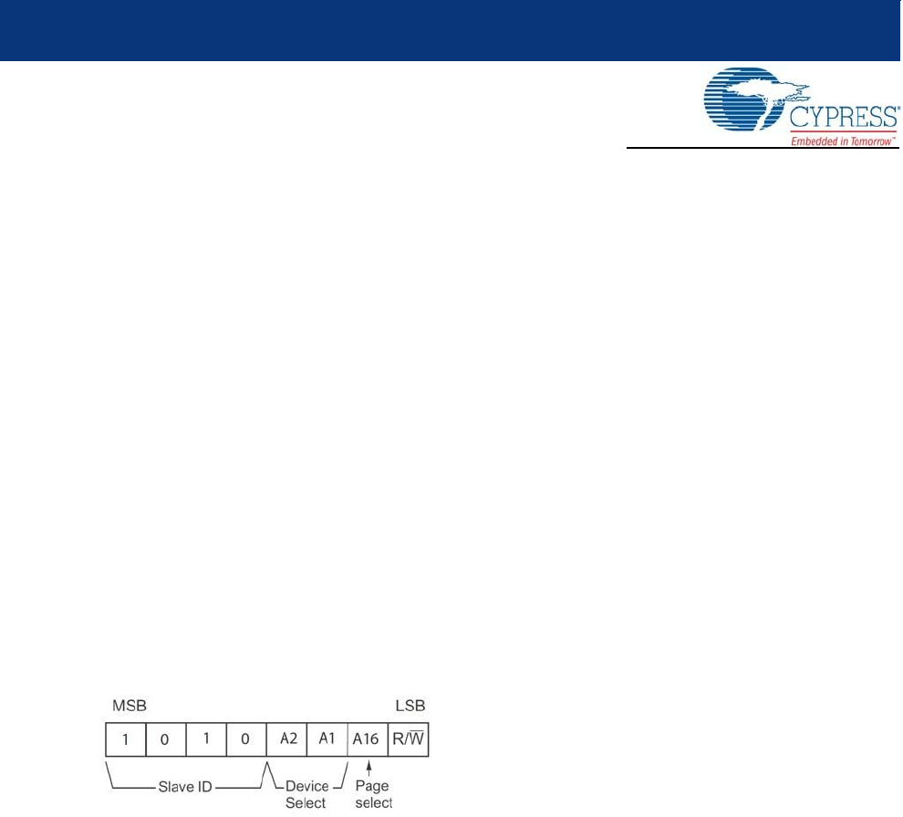
6.1.1 Address Selection
The slave address of the F-RAM device consists of three parts, as shown in Figure 6-1: slave ID,
device select, and page select. Slave ID is an F-RAM family-specific ID located in the datasheet of
the particular F-RAM device. For the device used in the BLE Pioneer Baseboard (FM24V10), the
slave ID is 1010b. Device select bits are set using the two physical pins A2 and A1 in the device. The
setting of these two pins on the BLE Pioneer Baseboard is controlled by resistors R32/R36 (A1) and
R33/R37 (A2). Because the memory location in F-RAM is divided into two pages of 64KB each, the
page select bit is used to refer to one of the two pages in which the read or write operations will take
place.
Figure 6-1. F-RAM I2C Address Byte Structure
CY8CKIT-042-BLE-A Bluetooth® Low Energy (BLE) Pioneer Kit Guide, Doc. # 002-11468 Rev. *A 117
Advanced Topics
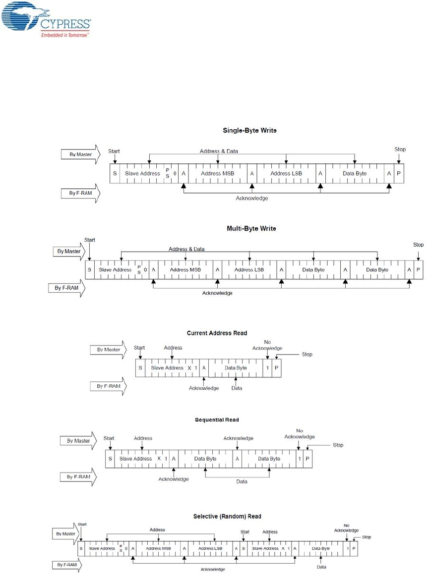
6.1.2 Write/Read Operation
The device datasheet includes details on how to perform a write/read operation with the F-RAM.
Figure 6-2 and Figure 6-3 provide a snapshot of the write/read packet structure as a quick reference.
Figure 6-2. F-RAM Single-Byte and Multiple-Byte Write Packet Structure
Figure 6-3. F-RAM Single-Byte and Multiple-Byte Read Packet Structure
As shown in the figures, all operations start with the slave address followed by the memory address.
For write operations, the bus master sends each byte of data to the memory, and the memory
generates an acknowledgement condition. For read operations, after receiving the complete slave
address and memory address, the memory begins shifting data from the current address on the next
clock.

CY8CKIT-042-BLE-A Bluetooth® Low Energy (BLE) Pioneer Kit Guide, Doc. # 002-11468 Rev. *A 118
A. Appendix
A.1 Bill of Materials (BOM)
A.1.1 BLE Pioneer Baseboard
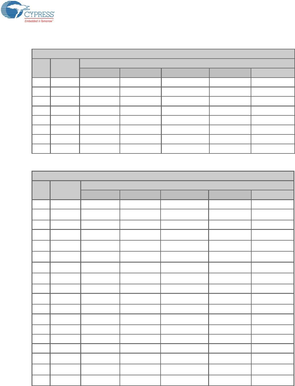
Item Qty Reference Value Description Manufacturer Mfr Part Number
1 1 PCB - Printed circuit board Cypress 600-60194-01, Rev04
2 1 BT1 CR2032 Bat-
tery Holder
HOLDER COIN CELL
CR2032 EJECT MPD BA2032
3 1 C1 1.0 uF CAP TANT 1UF 35V 10%
1210 AVX Corporation TAJB105K035RNJ
4 1 C2 4.7 uF CAP TANT 4.7UF 20V 10%
1210 AVX Corporation TAJB475K020RNJ
5 1 C3 0.01 uFd CAP 10000PF 16V
CERAMIC 0402 SMD TDK Corporation C1005X7R1C103K050B
A
6 1 C4 100 uFd CAP CER 100UF 6.3V 20%
X5R 1210 TDK Corporation C3225X5R0J107M250A
C
7 15
C5,C8,C9,C10,C1
2,C14,C17,C18,C
19,C21,C23,C25,
C26,C27,C28
0.1 uFd CAP .1UF 16V CERAMIC
X5R 0402 TDK Corporation C1005X5R1A104K050B
A
8 7 C6,C7,C11,C13,C
15,C16,C20 1.0 uFd CAP CERAMIC 1.0UF 25V
X5R 0603 10% Taiyo Yuden TMK107BJ105KA-T
9 1 C29 33 uF CAP CER 33UF 6.3V 20%
X5R 0805 TDK Corporation C2012X5R0J336M125A
C
10 6 D1,D2,D3,D4,D5,
D10 MBR0520L DIODE SCHOTTKY 0.5A
20V SOD-123
Fairchild Semicon-
ductor MBR0520L
11 3 D6,D7,D8 ESD diode SUPPRESSOR ESD 5VDC
0603 SMD Bourns Inc. CG0603MLC-05LE
12 1 D9 3.9V Zener DIODE ZENER 3.9V 500MW
SOD12 Diodes Inc BZT52C3V9-7-F
13 1 D11 2.7V Zener DIODE ZENER 2.7V 500MW
SOD123 ON Semiconductor MMSZ4682T1G
14 1 F1 FUSE PTC RESETTABLE .50A
15V 1812 Bourns MF-MSMF050-2
15 2 J1, J4 8x1 RECP CONN HEADER FEMALE
8POS .1" GOLD
Protectron Electro-
mech P9401-08-21
16 1 J2 6x2 RECP CONN HEADER FMAL
12PS.1" DL GOLD
Protectron Electro-
mech P9403-12-21

CY8CKIT-042-BLE-A Bluetooth® Low Energy (BLE) Pioneer Kit Guide, Doc. # 002-11468 Rev. *A 119
17 1 J3 10x1 RECP CONN HEADER FMALE
10POS .1" GOLD
Protectron Electro-
mech P9401-10-21
18 1 J6 50MIL KEYED
SMD
CONN HEADER 10 PIN
50MIL KEYED SMD Samtec FTSH-105-01-L-DV-K
19 1 J8 8X2 RECP CONN HEADER FMAL
16PS.1" DL GOLD
Protectron Electro-
mech P9403-16-21
20 1 J10 12X2 RECP CONN HEADER 2.54MM
24POS GOLD
Sullins Connector
Solutions
SBH11-PBPC-D12-ST-
BK
21 1 J11 10X2 RECP CONN HEADER 2.54MM
20POS GOLD
Sullins Connector
Solutions
SBH11-PBPC-D10-ST-
BK
22 1 J13 USB MINI B MINI USB RCPT R/A DIP TE Connectivity 1734510-1
23 1 J14 1X1 RECP CONN RCPT 1POS .100"
SNGL HORZ Samtec Inc BCS-101-L-S-HE
24 1 J15 2p_jumper CONN HEADR BRKWAY
.100 2POS STR
Protectron Electro-
mech P9101-02-12-1
25 1 J16 3p_jumper CONN HEADR BRKWAY
.100 3POS STR
Protectron Electro-
mech P9101-03-12-1
26 1 LED1 Power LED
Amber
LED 595NM AMB DIFF 0805
SMD
Avago Technolo-
gies HSMA-C170
27 1 LED2 Status LED
Green
LED GREEN CLEAR 0805
SMD Chicago Miniature CMD17-21VGC/TR8
28 1 LED3 RGB LED LED RED/GREEN/BLUE
PLCC4 SMD Cree, Inc. CLV1A-FKB-
CJ1M1F1BB7R4S3
29 3 L1,L2,L3 330 OHM @
100MHz
FERRITE CHIP 330 OHM
0805 Murata BLM21PG331SN1D
30 3 Q2,Q4,Q6 PMOS MOSFET P-CH 30V 2.2A
SOT23 ON Semiconductor NTR4171PT1G
31 1 Q1, PMOS MOSFET P-CH 30V 3.8A
SOT23-3 Diodes Inc DMP3098L-7
32 2 Q3,Q5 PMOS MOSFET P-CH 20V 3.5A
SOT23
NXP Semiconduc-
tors PMV48XP,215
33 1 R1 11K 1% RES 11K OHM 1/10W 1%
0603 SMD Panasonic - ECG ERJ-3EKF1102V
34 1 R2 560 ohm RES 560 OHM 1/8W 5%
0805 SMD Panasonic - ECG ERJ-6GEYJ561V
35 1 R3 14.7K 1% RES 14.7K OHM 1/10W 1%
0603 SMD Panasonic - ECG ERJ-3EKF1472V
36 1 R4 10K 1% RES 10K OHM 1/10W 1%
0603 SMD Panasonic - ECG ERJ-3EKF1002V
37 1 R5 4.3K 1% RES 4.3K OHM 1/10W 1%
0603 SMD Panasonic - ECG ERJ-3EKF4301V
38 1 R6 100K RES 100K OHM 1/10W 5%
0402 SMD Panasonic - ECG ERJ-2GEJ104X
39 14
R19,R26,R27,R3
6,R37,R38,R45,R
46,R47,R52,R53,
R54,R55,R56
ZERO RES 0.0 OHM 1/10W 0603
SMD Panasonic - ECG ERJ-3GEY0R00V
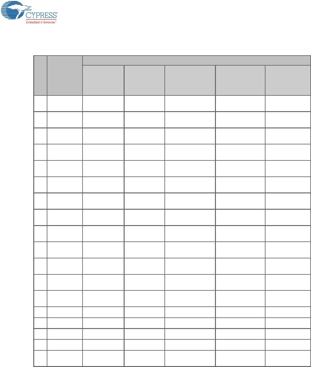
Item Qty Reference Value Description Manufacturer Mfr Part Number

CY8CKIT-042-BLE-A Bluetooth® Low Energy (BLE) Pioneer Kit Guide, Doc. # 002-11468 Rev. *A 120
40 2 R8,R58 15K RES 15K OHM 1/10W 1%
0603 SMD Panasonic - ECG ERJ-3EKF1502V
41 2 R9,R20 10K 1% RES 10K OHM 1/8W 1%
0805 SMD
Stackpole Electron-
ics Inc RMCF0805FT10K0
42 1 R10 10K RES 10K OHM 1/10W 5%
0603 SMD Panasonic - ECG ERJ-3GEYJ103V
43 1 R11 820 ohm RES 820 OHM 1/8W 5%
0805 SMD Panasonic - ECG ERJ-6GEYJ821V
44 2 R13,R14 ZERO RES 0.0 OHM 1/8W 0805
SMD Panasonic-ECG ERJ-6GEY0R00V
45 2 R15,R16 22E RES 22 OHM 1/10W 1%
0603 SMD Panasonic - ECG ERJ-3EKF22R0V
46 2 R17,R18 15K RES 15K OHM 1/10W 5%
0603 SMD Panasonic - ECG ERJ-3GEYJ153V
47 5 R22,R23,R28,R3
1,R35 2.2K RES 2.2K OHM 1/10W 5%
0603 SMD Panasonic - ECG ERJ-3GEYJ222V
48 2 R24,R25 30K RES 30K OHM 1/10W 5%
0603 SMD Panasonic - ECG ERJ-3GEYJ303V
49 2 R29,R30 1.5K RES 1.5K OHM 1/10W 5%
0603 SMD Panasonic - ECG ERJ-3GEYJ152V
50 5 R39,R40,R41,R4
2,R43 560 ohm RES 560 OHM 1/10W 5%
0603 SMD Panasonic - ECG ERJ-3GEYJ561V
51 2 SW1,SW2 SW PUSH-
BUTTON
SWITCH TACTILE SPST-
NO 0.05A 12V Panasonic - ECG EVQ-PE105K
52 1 TP5 BLACK TEST POINT PC MINI
.040"D Black
Keystone Electron-
ics 5001
53 2 TVS1,TVS2 5V 350W TVS UNIDIR 350W 5V SOD-
323 Dioded Inc. SD05-7
54 1 U1 LDO IC REG LDO ADJ 1A
TO252-5
Rohm Semiconduc-
tor BA00BC0WFP-E2
55 1 U2 PSoC 5LP
68QFN PSoC 5LP chip for
USB debug channel and
USB-Serial interface
Cypress Semicon-
ductor CY8C5868LTI-LP039
56 1 U3 F-RAM F-RAM 1-Mbit (128K X 8)
I2C interface
Cypress Semicon-
ductor FM24V10-G
57 1 U4 DUAL PMOS MOSFET 2P-CH 20V
430MA SOT-563 ON Semiconductor NTZD3152PT1G
Install on Bottom of PCB As per the Silk Screen in the Corners
58 4 N/A N/A BUMPER CYLIN 0.375" DIA
BLK 3M SJ61A4
Special Jumper Installation Instructions
59 2 J15,J16
Install jumper
across pins 1
and 2
Rectangular Connectors
MINI JUMPER GF 6.0MM
CLOSE TYPE BLACK
Kobiconn 151-8010-E
Item Qty Reference Value Description Manufacturer Mfr Part Number

CY8CKIT-042-BLE-A Bluetooth® Low Energy (BLE) Pioneer Kit Guide, Doc. # 002-11468 Rev. *A 121
Label
60 1 N/A N/A
LBL, PCA Label, Vendor
Code, Datecode, Serial
Number 121-60329-01 Rev
04 (YYWWVVXXXXX)
Cypress Semicon-
ductor
61 1 N/A N/A LBL, QR code, 12mm X
12mm
Cypress Semicon-
ductor
No load components
62 1 C22 0.1 uFd CAP .1UF 16V CERAMIC
Y5V 0402 TDK Corporation C1005X5R1A104K050B
A
63 1 C24 1.0 uFd CAP CERAMIC 1.0UF 25V
X5R 0603 10% Taiyo Yuden TMK107BJ105KA-T
64 9
R7,R59,R32,R33,
R34,R48,R49,R5
0,R51
Zero Ohm RES 0.0 OHM 1/10W JUMP
0603 TE Connectivity 1623094-1
65 1 R21 4.7K RES 4.7K OHM 1/10W 5%
0603 SMD Panasonic - ECG ERJ-3GEYJ472V
66 1 J7 50MIL KEYED
SMD
CONN HEADER 10 PIN
50MIL KEYED SMD Samtec FTSH-105-01-L-DV-K
67 1 J9 2 PIN HDR CONN HEADER FEMALE
2POS .1" GOLD
Sullins Connector
Solutions PPPC021LFBN-RC
68 2 TP4,TP5 BLACK TEST POINT 43 HOLE 65
PLATED BLACK
Keystone Electron-
ics 5001
69 3 TP1,TP2,TP3 RED TEST POINT 43 HOLE 65
PLATED RED
Keystone Electron-
ics 5000
70 2 R44,R12 ZERO RES 0.0 OHM 1/8W 0805
SMD Panasonic-ECG ERJ-6GEY0R00V
71 1 J12 3x2 RECPT CONN HEADER FMAL 6PS
.1" DL GOLD
Sullins Connector
Solutions PPPC032LFBN-RC
72 1 J5 6X1 RECP RA CONN FEMALE 6POS .100"
R/A GOLD
Sullins Connector
Solutions PPPC061LGBN-RC
Item Qty Reference Value Description Manufacturer Mfr Part Number

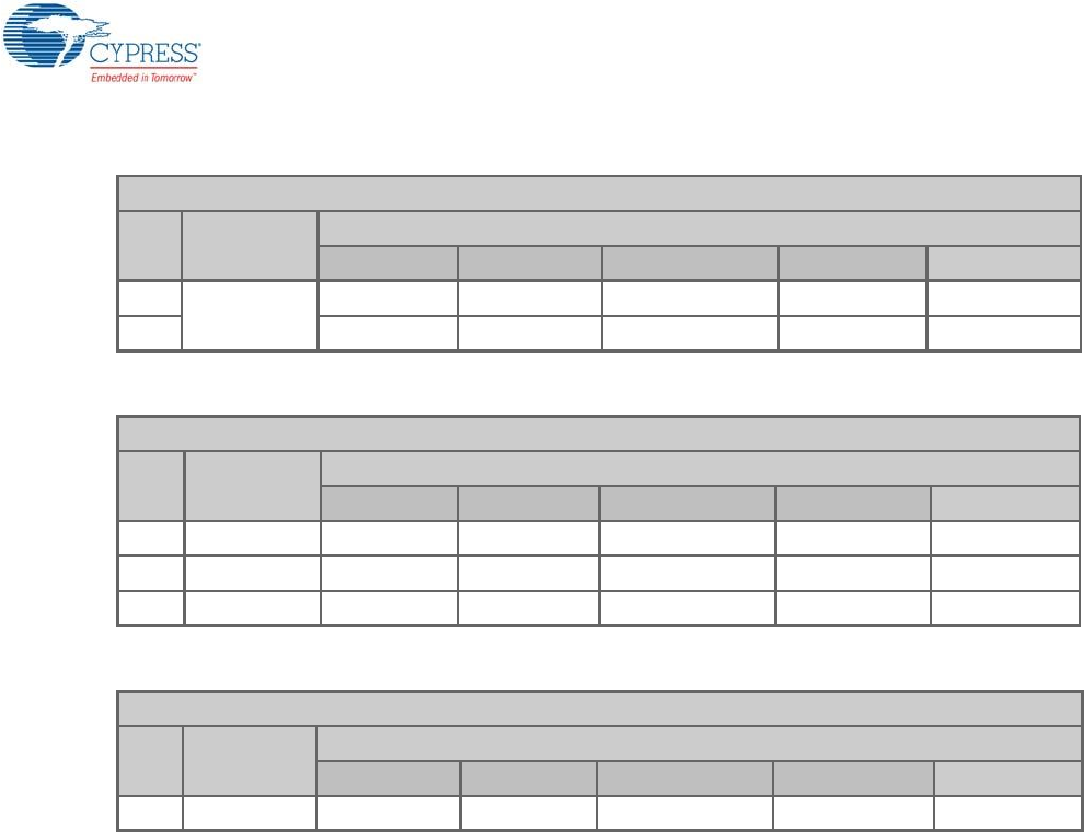
CY8CKIT-042-BLE-A Bluetooth® Low Energy (BLE) Pioneer Kit Guide, Doc. # 002-11468 Rev. *A 122
A.1.2 Module
A.1.2.1 CY5676A PRoC BLE 256KB Module
Item Qty Reference Value Description Mfr_Name Mfr_Part_Number
1 1 PCB - PRoC BLE 256KB Module
printed circuit board
Cypress qualified ven-
dor 600-60249-01 Rev 03
2 8 C1,C3,C5,C7,C
9,C11,C16,C18 0.1 uF CAP .1UF 16V CERAMIC Y5V
0402
Samsung Electro-
Mechanics America,
Inc
CL05F104ZO5NNNC
3 10
C2,C4,C6,C8,C
10,C12,C15,C1
7,C19,C20
1.0 uF CAP CERAMIC 1.0UF 25V
X5R 0603 10% TDK Corporation C1608X5R1E105K080AC
4 1 C21 2200 pF CAP CER 2200PF 50V 5%
NP0 0805 Murata Electronics GRM2165C1H222JA01D
5 1 C22 10000 pF CAP CER 10000PF 50V 5%
NP0 0805 Murata Electronics GRM2195C1H103JA01D
6 1 C23 36 pF CAP CER 36PF 50V 5% NP0
0402 Murata Electronics GRM1555C1H360JA01D
7 1 C24 18 pF CAP CER 18PF 50V 1% NP0
0402 Murata Electronics GRM1555C1H180FA01D
8 1 C14 1.5 pF CAP CER 1.5PF 50V NP0
0402
Johanson Technology
Inc 500R07S1R5BV4T
9 1 J1 HEADER
24
CONN HEADR FMALE
24POS .1" DL AU Sullins Connector SFH11-PBPC-D12-ST-BK
10 1 J2 HEADER
20
CONN HEADR FMALE
20POS .1" DL AU Sullins Connector SFH11-PBPC-D10-ST-BK
11 1 L1 6.8nH CER INDUCTOR 6.8NH 0402 Johanson Technology
Inc L-07C6N8JV6T
12 3 L2,L3,L4
330 Ohm
@100
MHz
FERRITE CHIP 330 OHM
0805 Murata Electronics BLM21PG331SN1D
13 1 U1 PRoC
BLE 56 QFN PRoC BLE - 256KB Cypress Semiconduc-
tor CYBL11573-56LQXI
14 1 Y1 32.768KH
z
CRYSTAL 32.768KHZ 12.5PF
SMD ECS Inc ECS-.327-12.5-34B
15 1 Y2 24MHz CRYSTAL 24.000 MHZ 8PF
SMD ECS Inc ECS-240-8-36CKM
16 1 LBL -
LBL, PCA Label, Vendor Code,
Datecode, Serial Number 121-
60216-01 Rev 01 (YYWWV-
VXXXXX)
Cypress qualified ven-
dor -
No Load components
17 1 C13 1.2 pF CAP CER 1.2PF 50V NP0
0402
Johanson Technology
Inc 500R07S1R2BV4T
18 1 C25 100pF CAP CER 100PF 50V 10%
X7R 0603 Kemet C0603C101K5RACTU
19 1 R1 Zero Ohm RES 0.0 OHM 1/8W 0605
SMD TE Connectivity 1623094-1

CY8CKIT-042-BLE-A Bluetooth® Low Energy (BLE) Pioneer Kit Guide, Doc. # 002-11468 Rev. *A 123
A.1.2.2 CY8CKIT-143A PSoC 4 BLE 256KB Module
20 1 R2 Rbleed No Load - -
21 1 R3 4.7K RES 4.7K OHM 1/10W 5%
0603 SMD Panasonic - ECG ERJ-3GEYJ472V
22 1 J3 4
HEADER
CONN HEADER 4POS .100 R/
A 15AU FCI 68016-204HLF
23 4 TP1,TP2,TP3,T
P4 RED TEST POINT 43 HOLE 65
PLATED RED Keystone Electronics 5000
24 1 TP5 BLACK TEST POINT 43 HOLE 65
PLATED BLACK Keystone Electronics 5001
Item Qty Reference Value Description Mfr_Name Mfr_Part_Number
1 1 PCB - PSoC 4 BLE 256KB Module
printed circuit board
Cypress qualified
vendor 600-60248-01 Rev 03
2 8 C1,C3,C5,C7,C9,
C11,C16,C18 0.1 uF CAP .1UF 16V CERAMIC
Y5V 0402
Samsung Electro-
Mechanics America,
Inc
CL05F104ZO5NNNC
3 10
C2,C4,C6,C8,C10
,C12,C15,C17,C1
9,C20
1.0 uF CAP CERAMIC 1.0UF 25V
X5R 0603 10% TDK Corporation C1608X5R1E105K080A
C
4 1 C21 2200 pF CAP CER 2200PF 50V 5%
NP0 0805 Murata Electronics GRM2165C1H222JA01D
5 1 C22 10000 pF CAP CER 10000PF 50V 5%
NP0 0805 Murata Electronics GRM2195C1H103JA01D
6 1 C23 36 pF CAP CER 36PF 50V 5% NP0
0402 Murata Electronics GRM1555C1H360JA01D
7 1 C24 18 pF CAP CER 18PF 50V 1% NP0
0402 Murata Electronics GRM1555C1H180FA01D
8 1 C14 1.5 pF CAP CER 1.5PF 50V NP0
0402
Johanson Technol-
ogy Inc 500R07S1R5BV4T
9 1 J1 HEADER
24
CONN HEADR FMALE
24POS .1" DL AU Sullins Connector SFH11-PBPC-D12-ST-
BK
10 1 J2 HEADER
20
CONN HEADR FMALE
20POS .1" DL AU Sullins Connector SFH11-PBPC-D10-ST-
BK
11 1 L1 6.8nH CER INDUCTOR 6.8NH 0402 Johanson Technol-
ogy Inc L-07C6N8JV6T
12 3 L2,L3,L4 330 Ohm
@100 MHz
FERRITE CHIP 330 OHM
0805 Murata Electronics BLM21PG331SN1D
13 1 U1 PSoC 4BLE 56 QFN PSoC 4 BLE - 256KB Cypress Semicon-
ductor CY8C4248LQI-BL583
14 1 Y1 32.768KHz CRYSTAL 32.768KHZ 12.5PF
SMD ECS Inc ECS-.327-12.5-34B
15 1 Y2 24MHz CRYSTAL 24.000 MHZ 8PF
SMD ECS Inc ECS-240-8-36CKM
Item Qty Reference Value Description Mfr_Name Mfr_Part_Number

CY8CKIT-042-BLE-A Bluetooth® Low Energy (BLE) Pioneer Kit Guide, Doc. # 002-11468 Rev. *A 124
16 1 LBL -
LBL, PCA Label, Vendor
Code, Datecode, Serial Num-
ber 121-60215-01 Rev 01
(YYWWVVXXXXX)
Cypress qualified
vendor -
No Load components
17 1 C13 1.2 pF CAP CER 1.2PF 50V NP0
0402
Johanson Technol-
ogy Inc 500R07S1R2BV4T
18 1 C25 100pF CAP CER 100PF 50V 10%
X7R 0603 Kemet C0603C101K5RACTU
19 1 R1 Zero Ohm RES 0.0 OHM 1/10W JUMP
0603 TE Connectivity 1623094-1
20 1 R2 Rbleed No Load - -
21 1 R3 4.7K RES 4.7K OHM 1/10W 5%
0603 SMD Panasonic - ECG ERJ-3GEYJ472V
22 1 J3 4 HEADER CONN HEADER 4POS .100
R/A 15AU FCI 68016-204HLF
23 4 TP1,TP2,TP3,TP
4RED TEST POINT 43 HOLE 65
PLATED RED Keystone Electronics 5000
24 1 TP5 BLACK TEST POINT 43 HOLE 65
PLATED BLACK Keystone Electronics 5001
Item Qty Reference Value Description Mfr_Name Mfr_Part_Number

CY8CKIT-042-BLE-A Bluetooth® Low Energy (BLE) Pioneer Kit Guide, Doc. # 002-11468 Rev. *A 125
A.1.3 CY5677 CySmart BLE 4.2 USB Dongle
Item Qty Reference Value Description Manufacturer Mfr Part Number
1 1 - - BLE Dongle Printed circuit
board
Cypress qualified
vendor 600-60326-01 Rev01
2 17
C1,C4,C6,C7,C9,
C11,C14,C16,C25
,C28,C29,C32,C3
5,C36,C38,C41,C
42
0.1 uFd CAP .1UF 16V CERAMIC Y5V
0402 TDK Corporation C1005X5R1A104K050BA
3 17
C2,C3,C5,C8,C10
,C12,C13,C15,C1
7,C18,C24,C26,C
30,C31,C33,C34,
C40
1.0 uFd CAP CERAMIC 1.0UF 25V
X5R 0603 10% Taiyo Yuden TMK107BJ105KA-T
4 1 C19 1.2 pFd CAP CER 1.2PF 50V NP0
0402
Johanson Technol-
ogy Inc 500R07S1R2BV4T
5 1 C22 36 pF CAP CER 36PF 50V 5% NP0
0402 Murata Electronics GRM1555C1H360JA01D
6 1 C23 18 pF CAP CER 18PF 50V 1% NP0
0402 Murata Electronics GRM1555C1H180FA01D
7 1 C39 0.01 uFd CAP 10000PF 16V CERAMIC
0402 SMD TDK Corporation C1005X7R1C103K050BA
8 3 D1,D2,D3 ESD diode SUPPRESSOR ESD 5VDC
0603 SMD Bourns Inc. CG0603MLC-05LE
9 1 F1 FUSE PTC RESETTABLE .50A 15V
1812 Bourns MF-MSMF050-2
10 1 J1 USB A
PLUG
CONN PLUG USB 4POS RT
ANG PCB Molex Inc 480370001
11 1 J2
50MIL
KEYED
SMD
CONN HEADER 10POS
DUAL SHRD SMD FCI 20021521-00010T1LF
12 1 LED1 Status
LED Blue
LED BLUE CLEAR THIN 0805
SMD LiteOn Inc LTST-C171TBKT
13 1 LED2
Status
LED
Green
LED GREEN CLEAR 0805
SMD Chicago Miniature CMD17-21VGC/TR8
14 1 LED3 Power
LED Red
LED SUPER RED CLEAR
0805 SMD LiteOn Inc LTST-C170KRKT
15 1 L1 5.1 nH CER INDUCTOR 5.1NH 0402 Johanson Technol-
ogy Inc L-07C5N1SV6T
16 2 R8,R11 Zero Ohm RES 0.0 OHM 1/8W 0805
SMD Panasonic-ECG ERJ-6GEY0R00V
17 1 R7 820 ohm RES 820 OHM 1/10W 5%
0603 SMD Panasonic - ECG ERJ-3GEYJ821V
18 2 R22,R25 820 ohm RES 820 OHM 1/8W 5% 0805
SMD Panasonic - ECG ERJ-6GEYJ821V
19 2 R9,R10 2.2K RES 2.2K OHM 1/10W 5%
0603 SMD Panasonic - ECG ERJ-3GEYJ222V

CY8CKIT-042-BLE-A Bluetooth® Low Energy (BLE) Pioneer Kit Guide, Doc. # 002-11468 Rev. *A 126
20 9
R1,R2,R3,R4,R12
,R13,R14,R15,R2
6
ZERO RES 0.0 OHM 1/10W 0603
SMD Panasonic - ECG ERJ-3GEY0R00V
21 2 R17,R18 22E RES 22 OHM 1/10W 1% 0603
SMD Panasonic - ECG ERJ-3EKF22R0V
22 1 R21 100K RES 100K OHM 1/10W 5%
0402 SMD Panasonic - ECG ERJ-2GEJ104X
23 2 R19,R20 15K RES 15K OHM 1/10W 5%
0603 SMD Panasonic - ECG ERJ-3GEYJ153V
24 2 R23,R24 30K RES 30K OHM 1/10W 5%
0603 SMD Panasonic - ECG ERJ-3GEYJ303V
25 2 SW1,SW2 SW RA
PUSH
SWITCH TACTILE SPST-NO
0.05A 12V Panasonic - ECG EVQ-P3401P
26 1 TVS1 5V 350W TVS UNIDIR 350W 5V SOD-
323 Diodes Inc. SD05-7
27 1 U1 PRoC
BLE PRoC BLE, 56QFN 256KB Cypress Semicon-
ductor CYBL11573-56LQXI
28 1 U2 DUAL
PMOS
MOSFET 2P-CH 20V 430MA
SOT-563 ON Semiconductor NTZD3152PT1G
29 1 U3 PSoC 5LP PSoC 5LP Programmable Sys-
tem on Chip, 68QFN
Cypress Semicon-
ductor CY8C5868LTI-LP039
30 1 Y1 32.768KH
z
CRYSTAL 32.768KHZ 12.5PF
SMD ECS Inc ECS-.327-12.5-34B
31 1 Y2 24MHz CRYSTAL 24.000 MHZ 8PF
SMD ECS Inc ECS-240-8-36CKM
32 1 N/A N/A
LBL, PCA Label, Vendor Code,
Datecode, Serial Number 121-
60161-01 Rev 03 (YYWWV-
VXXXXX); Only barcode
Cypress qualified
vendor -
No load components
33 1 C20 1.2 pF CAP CER 1.2PF 50V NP0
0402
Johanson Technol-
ogy Inc 500R07S1R2BV4T
34 1 C21 100pF CAP CER 100PF 50V 10%
X7R 0603 Kemet C0603C101K5RACTU
35 1 C37 0.1 uFd CAP .1UF 16V CERAMIC Y5V
0402 TDK Corporation C1005X5R1A104K050BA
36 1 C27 1.0 uFd CAP CERAMIC 1.0UF 25V
X5R 0603 10% Taiyo Yuden TMK107BJ105KA-T
37 1 R5 Zero Ohm RES 0.0 OHM 1/10W JUMP
0603 TE Connectivity 1623094-1
38 2 R6,R16 4.7K RES 4.7K OHM 1/10W 5%
0603 SMD Panasonic - ECG ERJ-3GEYJ472V
39 15
TP1,TP2,TP3,TP
4,TP5,TP6,TP7,T
P8,TP9,TP10,TP1
1,TP12,TP13,TP1
4,TP15
No load No load - -
Item Qty Reference Value Description Manufacturer Mfr Part Number

CY8CKIT-042-BLE-A Bluetooth® Low Energy (BLE) Pioneer Kit Guide, Doc. # 002-11468 Rev. *A 127
A.2 KitProg Status LED States
User Indication Scenario Action Required by user
LED blinks fast:
Frequency = 4.00 Hz
LED starts blinking at power up,
if bootloadable file is corrupt.
Bootload the KitProg.cyacd file: In PSoC Programmer, connect to
the kit, open the Utilities tab, and press the Upgrade Firmware
button.
LED blinks slow:
Frequency = 0.67 Hz
Entered Bootloader mode by
holding the Reset button of the
BLE Pioneer Kit/BLE Dongle
during kit power up.
Release the Reset button and replug power if you entered this
mode by mistake. If the mode entry was intentional, bootload the
new .cyacd file using the Bootloader Host tool shipped with PSoC
Creator.
LED blinks very fast:
Frequency = 15.0 Hz
SWD operation is in progress.
Any I2C traffic.
Kit's COM port connect/discon-
nect event (one blink).
In PSoC Programmer, watch the log window for status messages
for SWD operations. In the Bridge Control Panel, the LED blinks
on I2C command requests. In Bridge Control Panel or any other
serial port terminal program, distinguish the kit's COM port num-
ber by the blinking LED when the port is connected or discon-
nected.
LED is ON.
USB enumeration successful.
Kit is in the idle state waiting for
commands.
The kit functions can be used by PSoC Creator, PSoC Program-
mer, Bridge Control Panel, and any serial port terminal program.
LED is OFF. Power LED is ON.
This means that the USB enumeration was unsuccessful. This
can happen if the kit is not powered from the USB host or the kit is
not connected to the USB host through the USB cable. Verify the
USB cable and check if PSoC Programmer is installed on the PC.
CY8CKIT-042-BLE-A Bluetooth® Low Energy (BLE) Pioneer Kit Guide, Doc. # 002-11468 Rev. *A 128
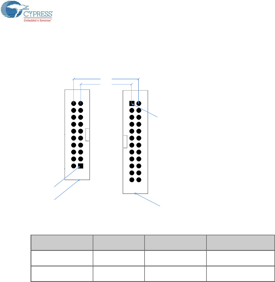
A.3 Adding BLE Module-Compatible Headers on Your Baseboard
The baseboard should have a 20-pin header and a 24-pin header. Dimension of these connectors
are given here.
Figure A-1. Connectors on BLE Pioneer Kit Baseboard
These headers are available for purchase from Digikey.
Description Manufacturer Manufacturer Part
Number Digikey Part Number
CONN HEADER 2.54MM
24POS GOLD
Sullins Connector
Solutions SBH11-PBPC-D12-ST-BK SBH11-PBPC-D12-ST-BK-
ND
CONN HEADER 2.54MM
20POS GOLD
Sullins Connector
Solutions SBH11-PBPC-D10-ST-BK S9172-ND
940 mils
740 mils
Pin 1
Pin 1
20 pin header
24 pin header
CY8CKIT-042-BLE-A Bluetooth® Low Energy (BLE) Pioneer Kit Guide, Doc. # 002-11468 Rev. *A 129
A.4 Programming BLE Modules via MiniProg3
If the BLE Modules are to be used without the BLE Pioneer Baseboard, they can be programmed
using MiniProg3. The J2 header has five adjacent pins – VDDD, GND, XRES, P0[7], and P0[6].
These pins can be used to program the BLE Module using MiniProg3.
Figure A-2. Programming a BLE Module via MiniProg3
Follow these steps to program the module:
1. Connect the MiniProg3 to the J2 connector, with the VDD of the MiniProg3 aligned to the VDDD
on the module.
2. Click Start > All Programs > Cypress > PSoC Programmer <version> > PSoC Programmer
<version>.
3. Open the desired .hex file in PSoC Programmer.
4. On the Programmer tab, set the Programming Mode to Reset.
5. Set AutoDetection to On.
6. Set Programmer Characteristics > Protocol to SWD.
7. Set Programmer Characteristics > Voltage to the desired value.
8. Click the Toggle Power icon below the menu bar to power the module.
9. Click the Program icon below the menu bar to program the module.
CY8CKIT-042-BLE-A Bluetooth® Low Energy (BLE) Pioneer Kit Guide, Doc. # 002-11468 Rev. *A 130
A.5 BLE Modules and BLE Dongles Compatible with the BLE Pioneer
Kit
Different BLE modules and BLE dongles can work with the BLE Pioneer Kit, as listed in the following
tables.
A.5.1 CY8CKIT-142 PSoC 4 BLE Module
This is the lower flash version of the PSoC 4 BLE Module. It can be ordered separately. This module
has the CY8C4247LQI-BL483 silicon, with 128KB flash and 16KB RAM. It supports Bluetooth 4.1.
Figure A-3. CY8CKIT-142 PSoC 4 BLE Module
BLE Module Availability Flash Size Bluetooth Version
CY8CKIT-142 PSoC 4 BLE Module Available separately 128KB Bluetooth 4.1
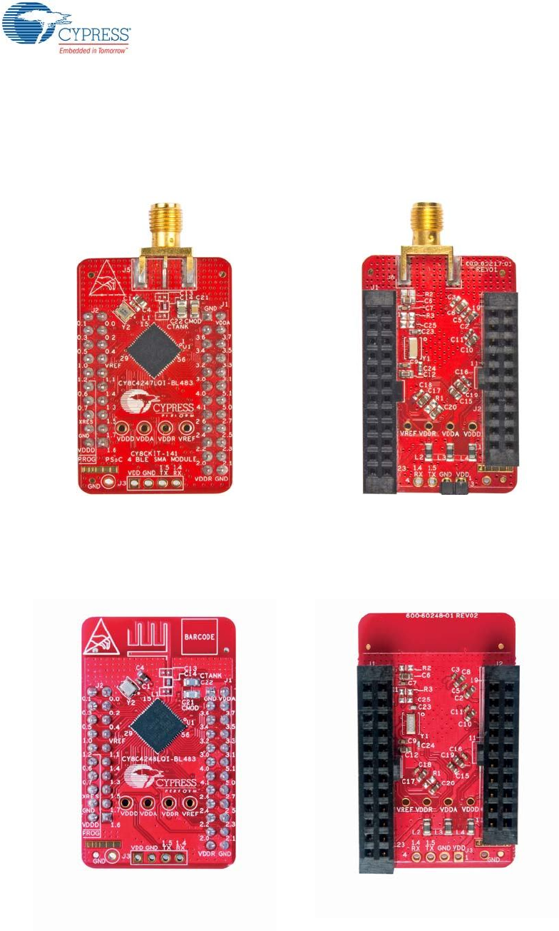
CY8CKIT-141 PSoC 4 BLE SMA Module Available separately 128KB Bluetooth 4.1
CY8CKIT-143 PSoC 4 BLE 256KB Module Available separately 256KB Bluetooth 4.1
CY8CKIT-143A PSoC 4 BLE 256KB Module As part of the kit 256KB Bluetooth 4.2
CY5671 PRoC BLE Module Available separately 128KB Bluetooth 4.1
CY5674 PRoC BLE SMA Module Available separately 128KB Bluetooth 4.1
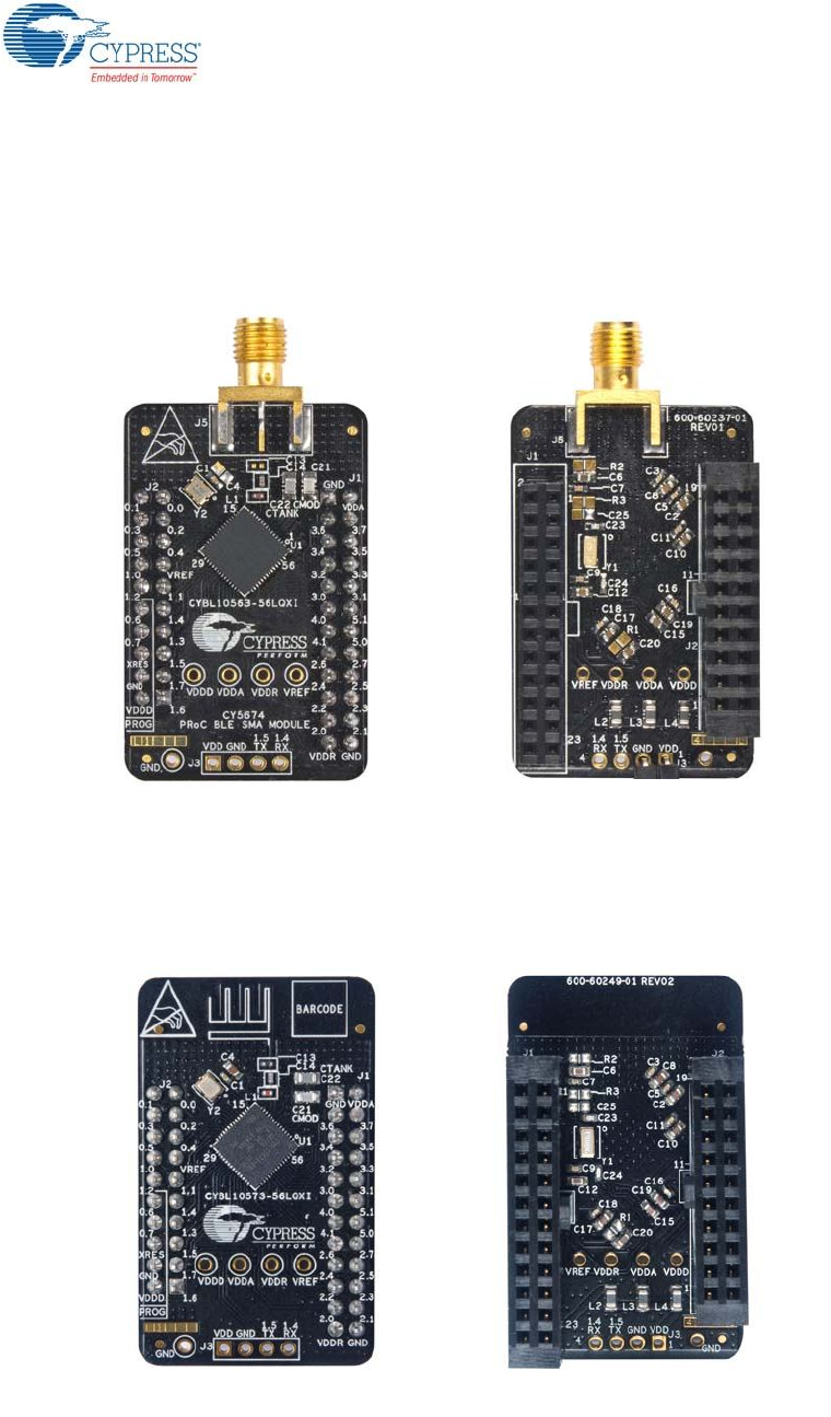
CY5676 PRoC BLE 256KB Module Available separately 256KB Bluetooth 4.1
CY5676A PRoC BLE 256KB Module As part of the kit 256KB Bluetooth 4.2
BLE Dongle Availability Flash Size Bluetooth Version
CY5670 CySmart USB Dongle (BLE Dongle) Available separately 128KB Bluetooth 4.1
CY5677 CySmart BLE 4.2 USB Dongle (BLE
Dongle) As part of the kit 256KB Bluetooth 4.2
CY8CKIT-042-BLE-A Bluetooth® Low Energy (BLE) Pioneer Kit Guide, Doc. # 002-11468 Rev. *A 131
A.5.2 CY8CKIT-141 PSoC 4 BLE SMA Module
This module is identical to the CY8CKIT-142 PSoC 4 BLE Module, except that it has an SMA con-
nector instead of a wiggle antenna; this connector can be used to connect to an external antenna.
This module can be ordered separately.
Figure A-4. CY8CKIT-141 PSoC 4 BLE SMA Module
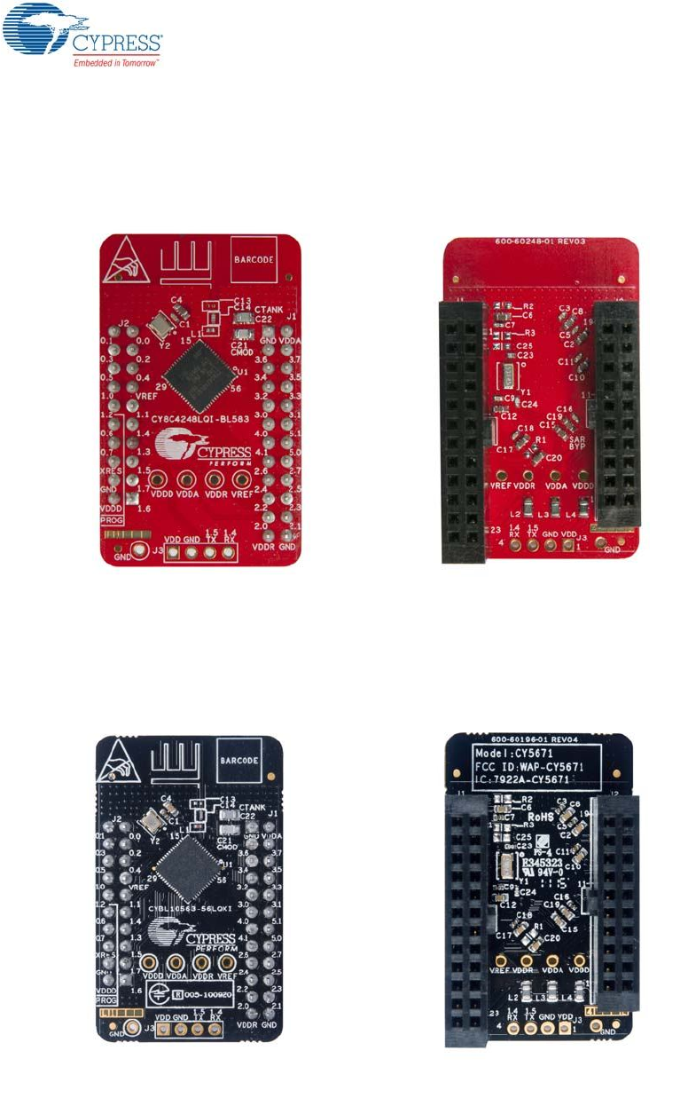
A.5.3 CY8CKIT-143 PSoC 4 BLE 256KB Module
This is the Bluetooth 4.1 equivalent of the CY8CKIT-143A PSoC 4 BLE 256KB Module. It has the
CY8C4248LQI-BL483 silicon, with 256KB flash and 32KB RAM. It can be ordered separately.
Figure A-5. CY8CKIT-143 PSoC 4 BLE 256KB Module
CY8CKIT-042-BLE-A Bluetooth® Low Energy (BLE) Pioneer Kit Guide, Doc. # 002-11468 Rev. *A 132
A.5.4 CY8CKIT-143A PSoC 4 BLE 256KB Module
This is the default PSoC 4 BLE Module shipped as part of the BLE Pioneer Kit. It supports Bluetooth
4.2 features and DMA. It has the CY8C4248LQI-BL583 silicon, with 256KB flash and 32KB RAM.
Figure A-6. CY8CKIT-143A PSoC 4 BLE 256KB Module
A.5.5 CY5671 PRoC BLE Module
This is the lower flash version of the PRoC BLE Module. It can be ordered separately. This module
has the CYBL10563-56LQXI silicon, with 128KB flash and 16KB RAM. It supports Bluetooth 4.1.
Figure A-7. CY5671 PRoC BLE Module
CY8CKIT-042-BLE-A Bluetooth® Low Energy (BLE) Pioneer Kit Guide, Doc. # 002-11468 Rev. *A 133
A.5.6 CY5674 PRoC BLE SMA Module
This module is identical to the CY5671 PRoC BLE Module, except that it has an SMA connector
instead of a wiggle antenna; this connector can be used to connect to an external antenna. This
module can be ordered separately.
Figure A-8. CY5674 PRoC BLE SMA Module
A.5.7 CY5676 PRoC BLE 256KB Module
This is the Bluetooth 4.1 equivalent of the CY5676A PRoC BLE 256KB Module. It has the
CYBL10573-56LQXI silicon, with 256KB flash and 32KB RAM. It can be ordered separately.
Figure A-9. CY5676 PRoC BLE 256KB Module
CY8CKIT-042-BLE-A Bluetooth® Low Energy (BLE) Pioneer Kit Guide, Doc. # 002-11468 Rev. *A 134
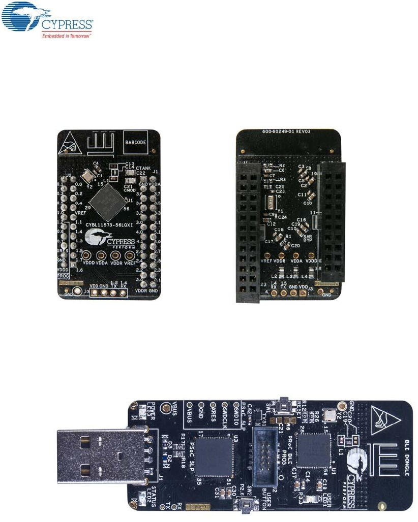
A.5.8 CY5676A PRoC BLE 256KB Module
This is the default PRoC BLE Module shipped as part of the BLE Pioneer Kit. It supports Bluetooth
4.2 features and DMA. It has the CYBL11573-56LQXI silicon, with 256KB flash and 32KB RAM.
Figure A-10. CY5676A PRoC BLE 256KB Module
A.5.9 CY5670 CySmart USB Dongle (BLE Dongle)
This is the lower flash equivalent of the CY5677 CySmart BLE 4.2 USB. It can be ordered sepa-
rately. This dongle has the CYBL10162-56LQXI silicon, with 128KB flash and 16KB RAM. It supports
Bluetooth 4.1.
Figure A-11. CY5670 CySmart USB Dongle (BLE Dongle)
CY8CKIT-042-BLE-A Bluetooth® Low Energy (BLE) Pioneer Kit Guide, Doc. # 002-11468 Rev. *A 135
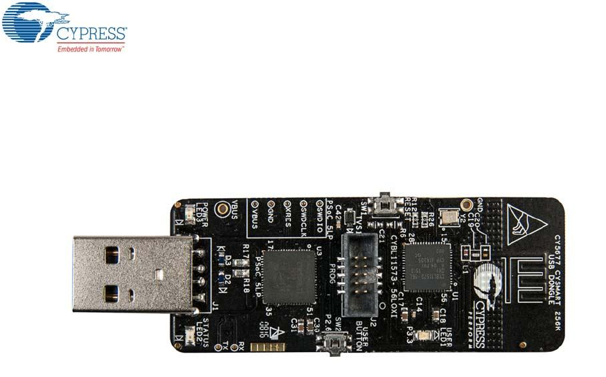
A.5.10 CY5677 CySmart BLE 4.2 USB Dongle (BLE Dongle)
This is the default BLE Dongle shipped as part of the BLE Pioneer Kit. It has the CYBL11573-
56LQXI silicon, with 256KB flash and 32KB RAM. It supports Bluetooth 4.2 and DMA.
Figure A-12. CY5677 CySmart BLE 4.2 USB Dongle (BLE Dongle)
CY8CKIT-042-BLE-A Bluetooth® Low Energy (BLE) Pioneer Kit Guide, Doc. # 002-11468 Rev. *A 136
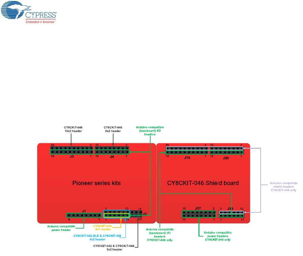
A.6 Migrating Projects Across Different Pioneer Series Kits
All Cypress Pioneer series kits are Arduino Uno-compatible and have some common onboard
peripherals such as RGB LED, CapSense, and a user switch. However, the pin mapping in each of
the boards is different due to differences in pin functions of the PSoC device used. This guide lists
the pin maps of the Pioneer series kits to allow easy migration of projects across different kits.
In some cases, the pins available on the Pioneer kit headers are a super set of the standard Arduino
Uno pins. For example, J2 contains only one row of pins on the Arduino Uno pinout while it contains
two rows of pins on many of the Pioneer series kits.
Figure A-13. Pioneer Series Kits Pin Map
CY8CKIT-042-BLE-A Bluetooth® Low Energy (BLE) Pioneer Kit Guide, Doc. # 002-11468 Rev. *A 137
A.6.1 Arduino Uno-Compatible Headers
J1 Arduino-Compatible Header Pin Map
Pin # Arduino
Pin
Pioneer Series Kits
CY8CKIT-042 CY8CKIT-040 CY8CKIT-042-BLE CY8CKIT-044 CY8CKIT-046
1 VIN VIN VIN VIN VIN VIN
2 GND GND GND GND GND GND
3 GND GND GND GND GND GND
4 5V V5.0 V5.0 V5.0 V5.0 V5.0
5 3.3V V3.3 V3.3 V3.3 V3.3 V3.3
6 RESET RESET RESET RESET RESET RESET
7 IOREF P4.VDD P4.VDD BLE.VDD P4.VDD P4L.VDD
8 NC NC NC NC NC NC
J2 Arduino-Compatible Header Pin Map
Pin # Arduino
Pin
Pioneer Series Kits
CY8CKIT-042 CY8CKIT-040 CY8CKIT-042-BLE CY8CKIT-044 CY8CKIT-046
1 A0 P2[0] P0[0] P3[0] P2[0] P2[0]
2 – P0[2]a
a. These pins are also used for onboard peripherals. See the tables in “Onboard Peripherals” on page 140 for connection details.
– P2[0] P2[6]aP3[6]a
3 A1 P2[1] P0[1] P3[1] P2[1] P2[1]
4 –- P0[3]a–P2[1]aP6[5]aP3[7]a
5 A2 P2[2] P0[2]aP3[2] P2[2] P2[2]
6 – P4_VDD – P2[2]aP0[6]aP9[0]
7 A3 P2[3] P0[4]aP3[3] P2[3] P2[3]
8 – P1[5]a–P2[3]aP4[4]aP9[1]
9 A4 P2[4] P1[3] P3[4] P2[4] P2[4]
10 – P1[4]a–P2[4]aP4[5]aP9[2]
11 A5 P2[5] P1[2] P3[5] P2[5] P2[5]
12 – P1[3]a–P2[5]aP4[6]aP9[3]
13 – P0[0] – – P0[0] –
14 – GND – – GND –
15 – P0[1] – – P0[1] –
16 – P1[2]a– – P3[4]a–
17 – P1[0] – – P0[7]a–
18 – P1[1]a– – P3[5]a–

CY8CKIT-042-BLE-A Bluetooth® Low Energy (BLE) Pioneer Kit Guide, Doc. # 002-11468 Rev. *A 138
J3 Arduino-Compatible Header Pin Map
#Arduino
Pin
Pioneer Series Kits
CY8CKIT-042 CY8CKIT-040 CY8CKIT-042-BLE CY8CKIT-044 CY8CKIT-046
1 D8 P2[6] P1[4] P0[5] P0[2] P0[2]
2 - - - - - P3[4]
3 D9 P3[6] P1[5] P0[4] P0[3] P0[3]
4 - - - - - P6[5]
5 D10 P3[4] P1[6] P0[2] P2[7] P6[3]
6 - - - - - P6[3]
7 D11 P3[0] P1[1]a
a. These pins are also used for onboard peripheral connections. Refer to the A.6.2 Onboard Peripherals section for connection details.
P0[0] P6[0] P6[0]
8 - - - - - P6[0]
9 D12 P3[1] P3[1] P0[1] P6[1] P6[1]
10 - - - - - P6[1]
11 D13 P0[6] P1[7] P0[3] P6[2] P6[2]
12 - - - - - P6[2]
13 GND GND GND GND GND GND
14 - - - - - GND
15 AREF P1[7] NC VREF P1[7] VREF
16 - - - - - VREF
17 SDA P4[1] P1[3] P3[4] P4[1] P4[1]
18 - - - - - P4[1]
19 SCL P4[0] P1[2] P3[5] P4[0] P4[0]
20 - - - - - P4[0]

CY8CKIT-042-BLE-A Bluetooth® Low Energy (BLE) Pioneer Kit Guide, Doc. # 002-11468 Rev. *A 139
J4 Arduino-Compatible Header Pin Map
#Arduino
Pin
Pioneer Series Kits
CY8CKIT-042 CY8CKIT-040 CY8CKIT-042-BLE CY8CKIT-044 CY8CKIT-046
1 D0 P0[4] P0[5] P1[4] P3[0] P3[0]
2 - - - - - P8[0]
3 D1 P0[5] P0[6] P1[5] P3[1] P3[1]
4 - - - - - P8[1]
5 D2 P0[7]a
a. These pins are also used for onboard peripheral connections. Refer to the A.6.2 Onboard Peripherals section for connection details.
P0[7] P1[6] P1[0] P1[0]
6 - - - - - P8[2]
7 D3 P3[7] P3[2]aP1[7] P1[1] P1[1]
8 - - - - - P8[3]
9 D4 P0[0] P0[3] P1[3] P1[2] P1[2]
10 - - - - - P8[4]
11 D5 P3[5] P3[0] P1[2] P1[3] P1[3]
12 - - - - - P8[5]
13 D6 P1[0] P1[0] P1[1] P5[3] P5[6]
14 - - - - - P8[6]
15 D7 P2[7] P2[0]aP1[0] P5[5] P5[5]
16 - - - - - P8[7]
CY8CKIT-042-BLE-A Bluetooth® Low Energy (BLE) Pioneer Kit Guide, Doc. # 002-11468 Rev. *A 140
A.6.2 Onboard Peripherals
#CapSense
Pin
Pioneer Series Kits
CY8CKIT-042
(Linear Slider) CY8CKIT-040 CY8CKIT-042-BLE
(Linear Slider)
CY8CKIT-044
(Gesture Pad)
CY8CKIT-046
(Gesture Pad
with Radial
Slider)a
a. The CapSense elements are present on the CY8CKIT-046 shield board. The radial slider (CapSense sensors 6 to 13) is symmetric and the
sensor order can be shifted to fit your requirement, that is, the desired zero position on the slider.
1CapSense
Sensor 1
P1[1]/
CS_LS_E0 – P2[1]/CS_LS_E0 P4[4]/
CS_GES_CR
P0[6]/
CS_GES_CR
2CapSense
Sensor 2
P1[2]/
CS_LS_E1 – P2[2]/CS_LS_E1 P4[5]/
CS_GES_UP
P4[5]/
CS_GES_LT
3CapSense
Sensor 3
P1[3]/
CS_LS_E2 – P2[3]/CS_LS_E2 P4[6]
/CS_GES_LT
P4[4]/
CS_GES_UP
4CapSense
Sensor 4
P1[4]/
CS_LS_E3 – P2[4]/CS_LS_E3 P3[4]/
CS_GES_DN
P4[7]/
CS_GES_RT
5CapSense
Sensor 5
P1[5]/
CS_LS_E4 – P2[5]/CS_LS_E4 P3[5]/
CS_GES_RT
P4[6]/
CS_GES_DN
6CapSense
Sensor 10 – – – – P7[4]/
CS_RS_E0
7CapSense
Sensor 11 – – – – P7[5]/
CS_RS_E1
8CapSense
Sensor 12 – – – – P7[6]/
CS_RS_E2
9CapSense
Sensor 13 – – – – P7[7]/
CS_RS_E3
10 CapSense
Sensor 6 – – – – P0[0]/
CS_RS_E4
11 CapSense
Sensor 7 – – – – P0[1]/
CS_RS_E5
12 CapSense
Sensor 8 – – – – P7[2]/
CS_RS_E6
13 CapSense
Sensor 9 – – – – P7[3]/
CS_RS_E7
14 CMODb
b. CMOD0, CTANK0, CMOD1, and CTANK1 are only present in the CY8CKIT-046 PSoC 4 L-Series Pioneer Kit.
P4[2] P0[4] P4[0] P4[2] P4[2]
15 CTANKbP4[3] P0[2] P4[1] P4[3] P4[3]
16 CMODb– – – – P5[0]
17 CTANKb– – – – P5[1]
18 CapSense
Shield P0[1] – P1[6] P0[1] P0[2]
CY8CKIT-042-BLE-A Bluetooth® Low Energy (BLE) Pioneer Kit Guide, Doc. # 002-11468 Rev. *A 141
Proximity Header Pin Map
Pin # Description Pioneer Series Kits
CY8CKIT-042 CY8CKIT-040 CY8CKIT-042-BLE CY8CKIT-044 CY8CKIT-046
1PROXIMITY – P2[0] P2[0] P3[7] P9[4]
2 – – – P3[6] P9[5]
RGB LED Pin Map
Pin # Color Pioneer Series Kits
CY8CKIT-042 CY8CKIT-040 CY8CKIT-042-BLE CY8CKIT-044 CY8CKIT-046
1 Red P1[6] P3[2] P2[6] P0[6] P5[2]
2 Green P0[2] P1[1] P3[6] P2[6] P5[3]
3 Blue P0[3] P0[2] P3[7] P6[5] P5[4]
User Switch Pin Map
Pin # Description Pioneer Series Kits
CY8CKIT-042 CY8CKIT-040 CY8CKIT-042-BLE CY8CKIT-044 CY8CKIT-046
1 SW2 P0[7] – P2[7] P0[7] P0[7]

CY8CKIT-042-BLE-A Bluetooth® Low Energy (BLE) Pioneer Kit Guide, Doc. # 002-11468 Rev. *A 142
Revision History
CY8CKIT-042-BLE-A Bluetooth® Low Energy (BLE) Pioneer Kit Guide Revision History
Document Title: CY8CKIT-042-BLE-A Bluetooth® Low Energy (BLE) Pioneer Kit Guide
Document Number: 002-11468
Revision ECN
Number Issue Date Origin of
Change Description of Change
** 5162292 03/04/2016 UDYG New kit guide.
*A 05/25/2016 AARA
Updated Safety Information chapter on page 6:
Added “Regulatory Compliance Information” on page 8.
Updated to new template.