D Link 2001120011-1 Wireless LAN CardBus PC Card User Manual 2nd Revised UsersGuide
D Link Corporation Wireless LAN CardBus PC Card 2nd Revised UsersGuide
UserManual.wiki
>
D Link
>
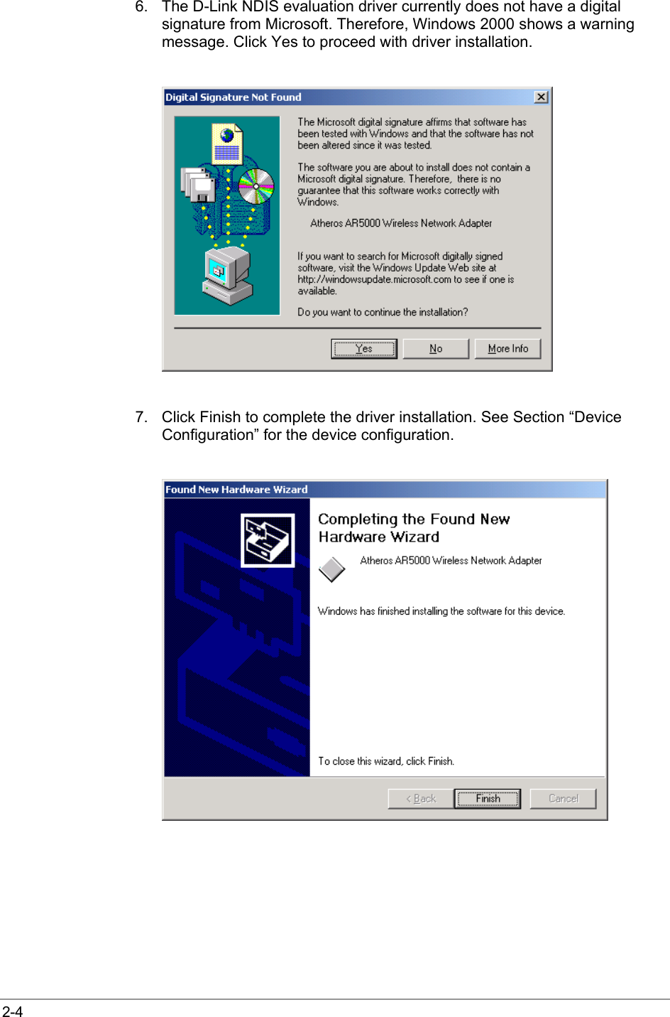
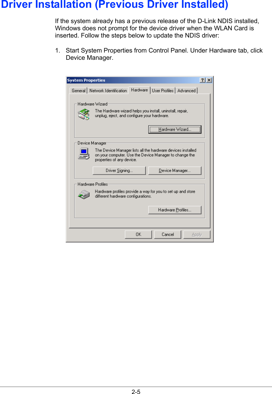
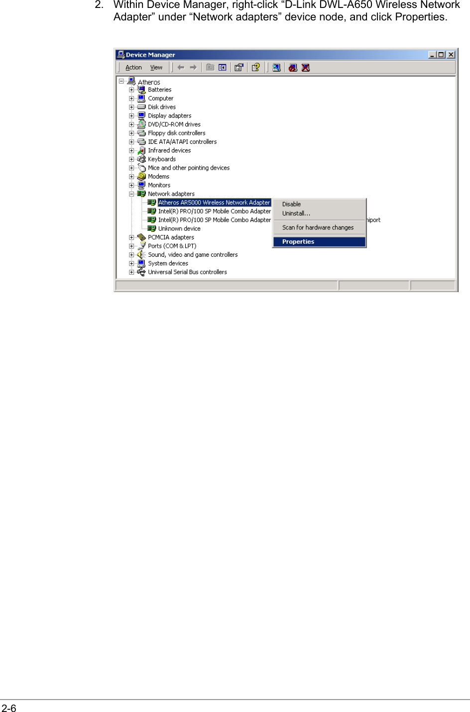
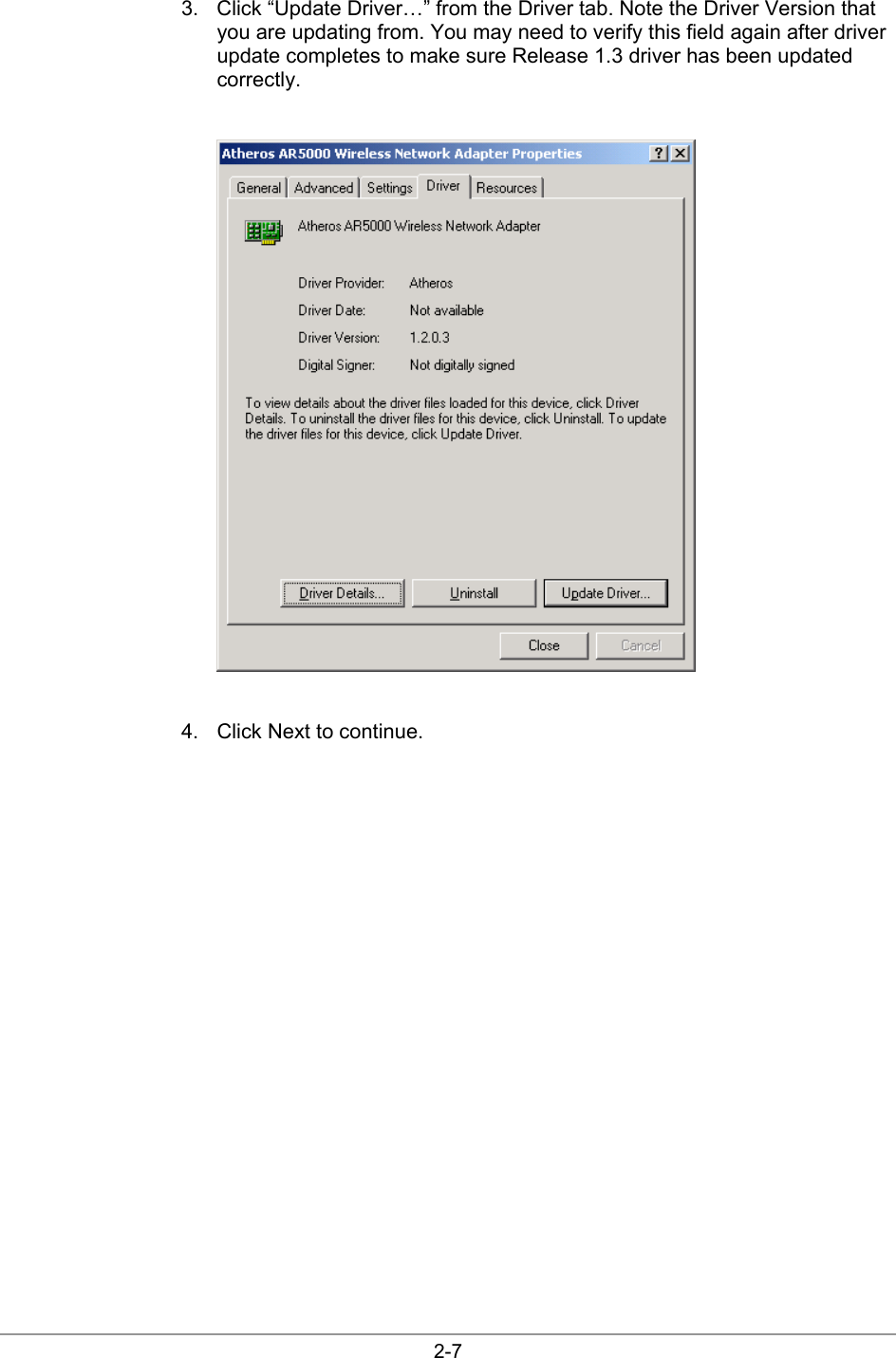
2001120011 1 User Manual
Revision 3 of Users Manual
Navigation menu
Upload a User Manual
Namespaces
Wiki Guide
HTML
PDF
Info
Views
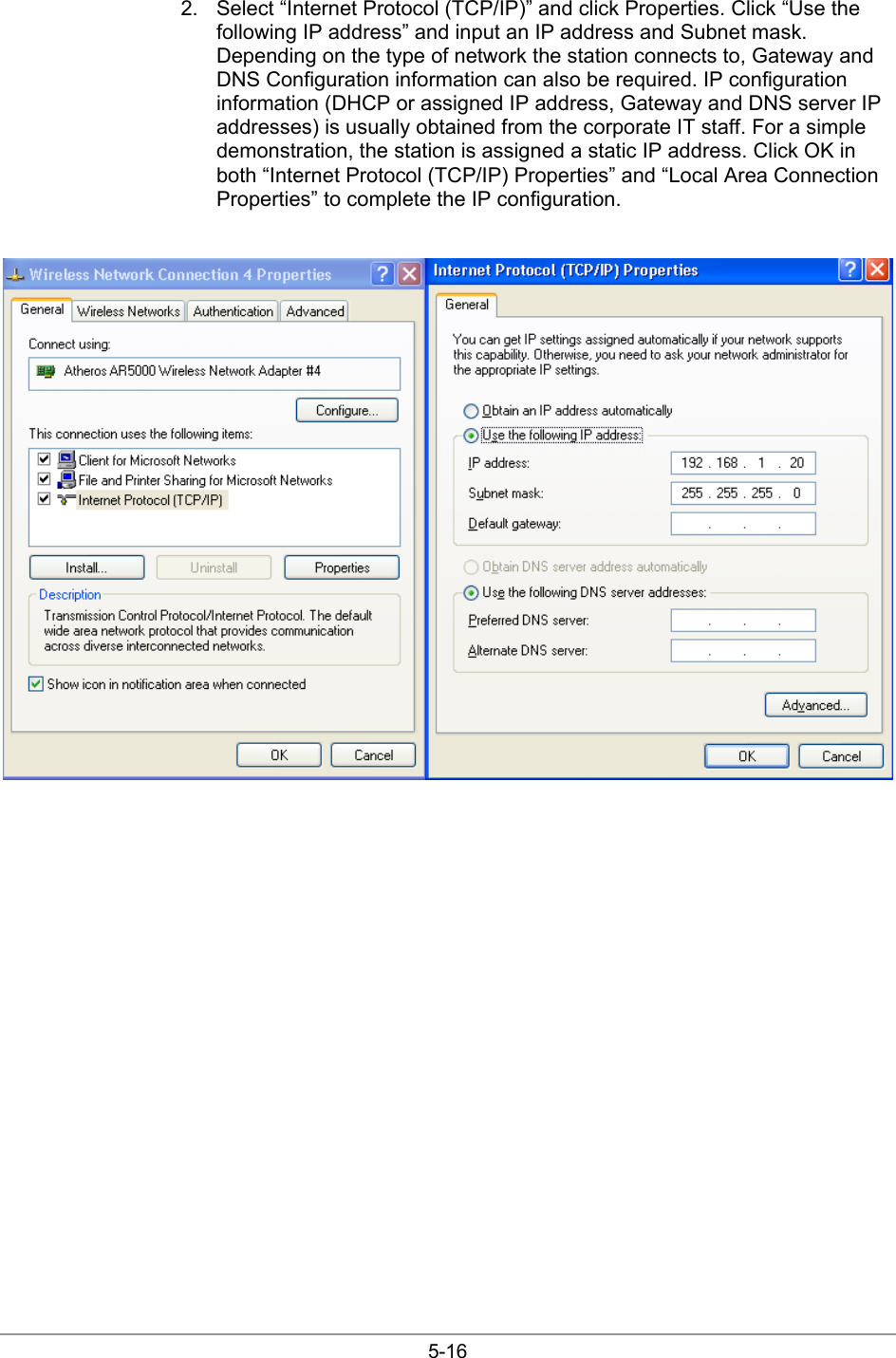
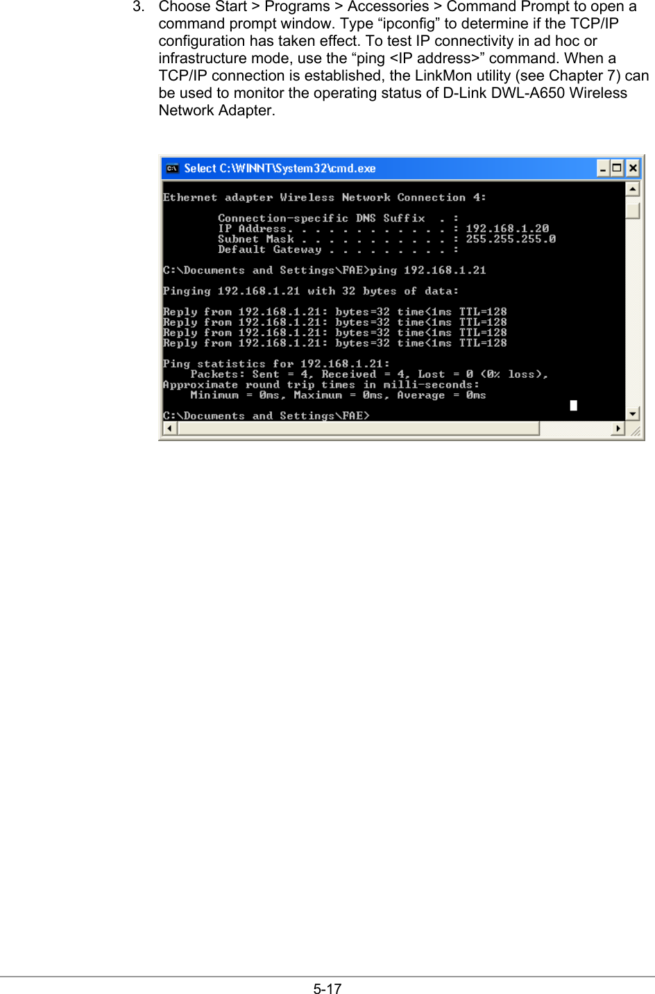
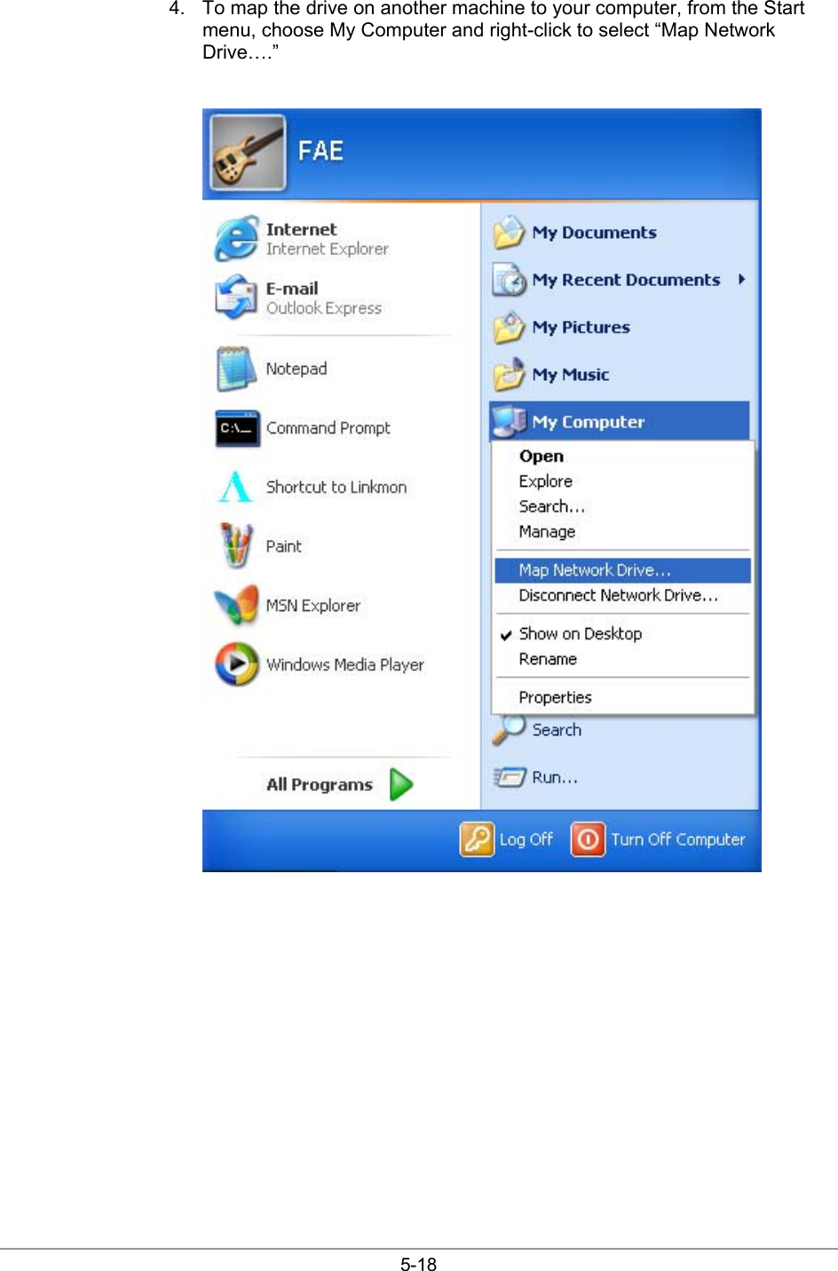
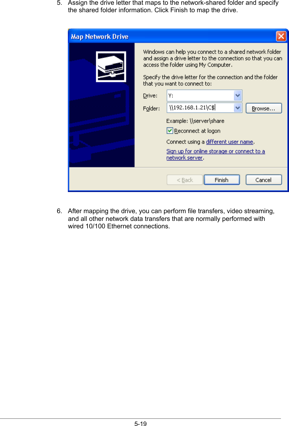
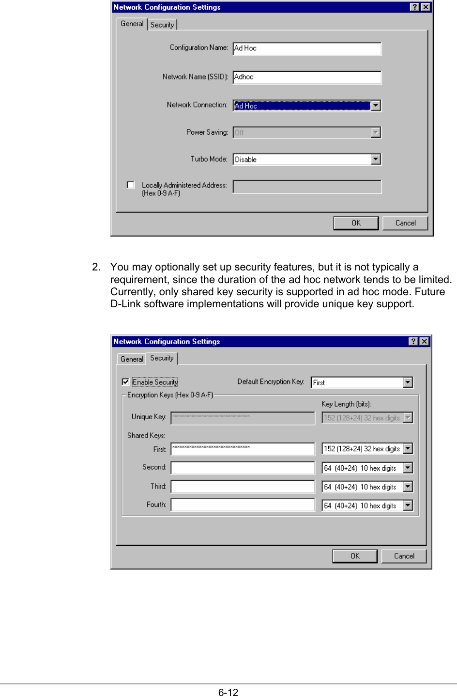
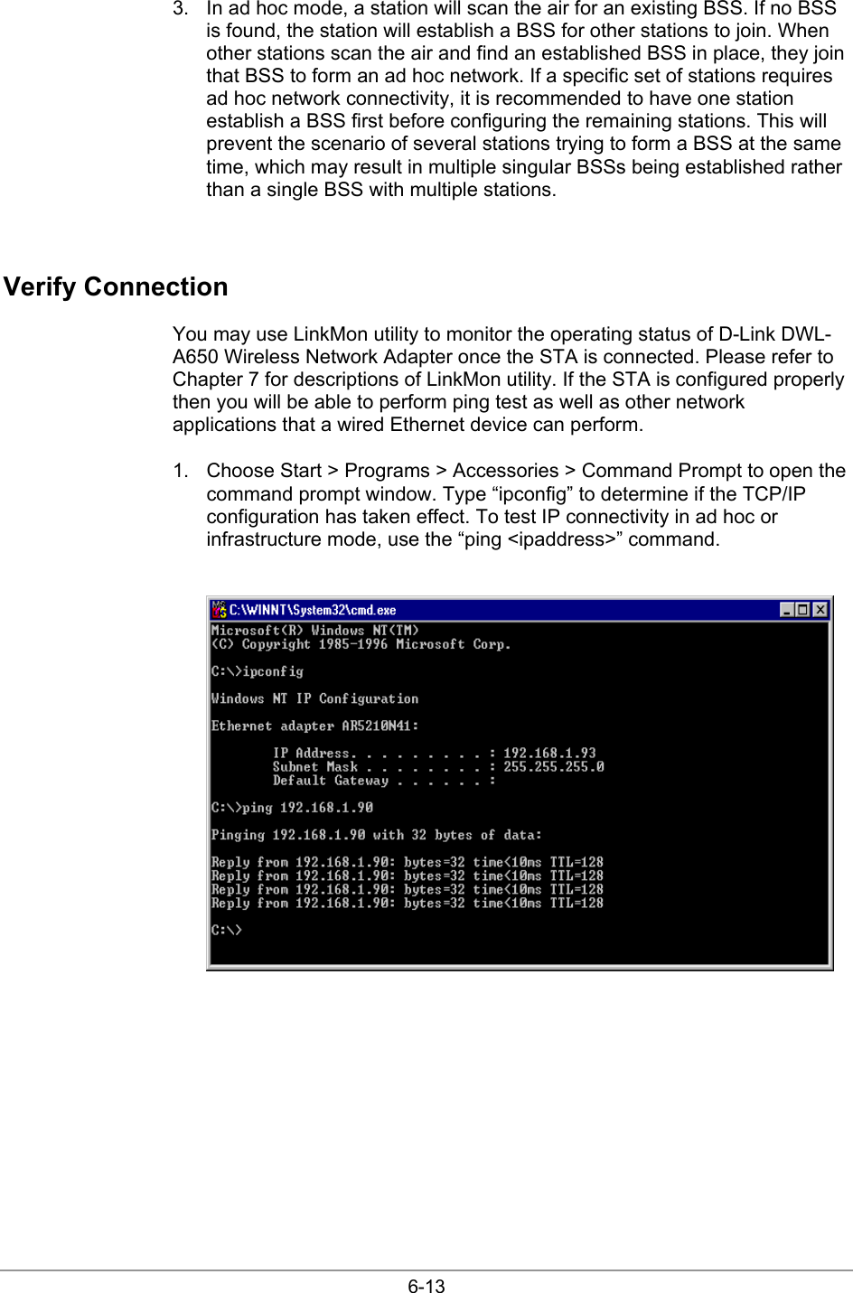
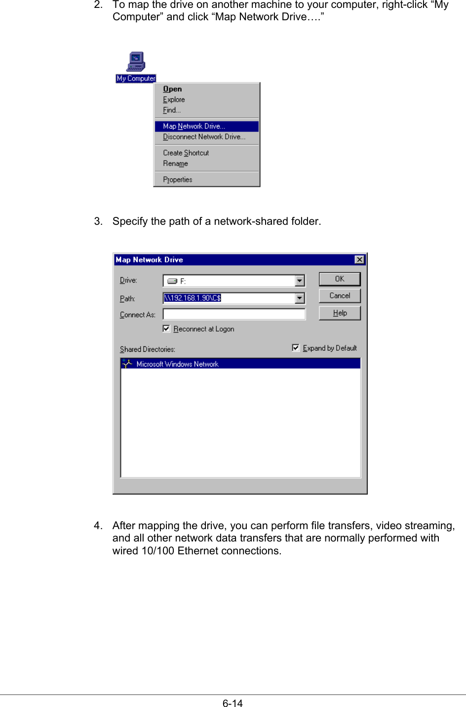
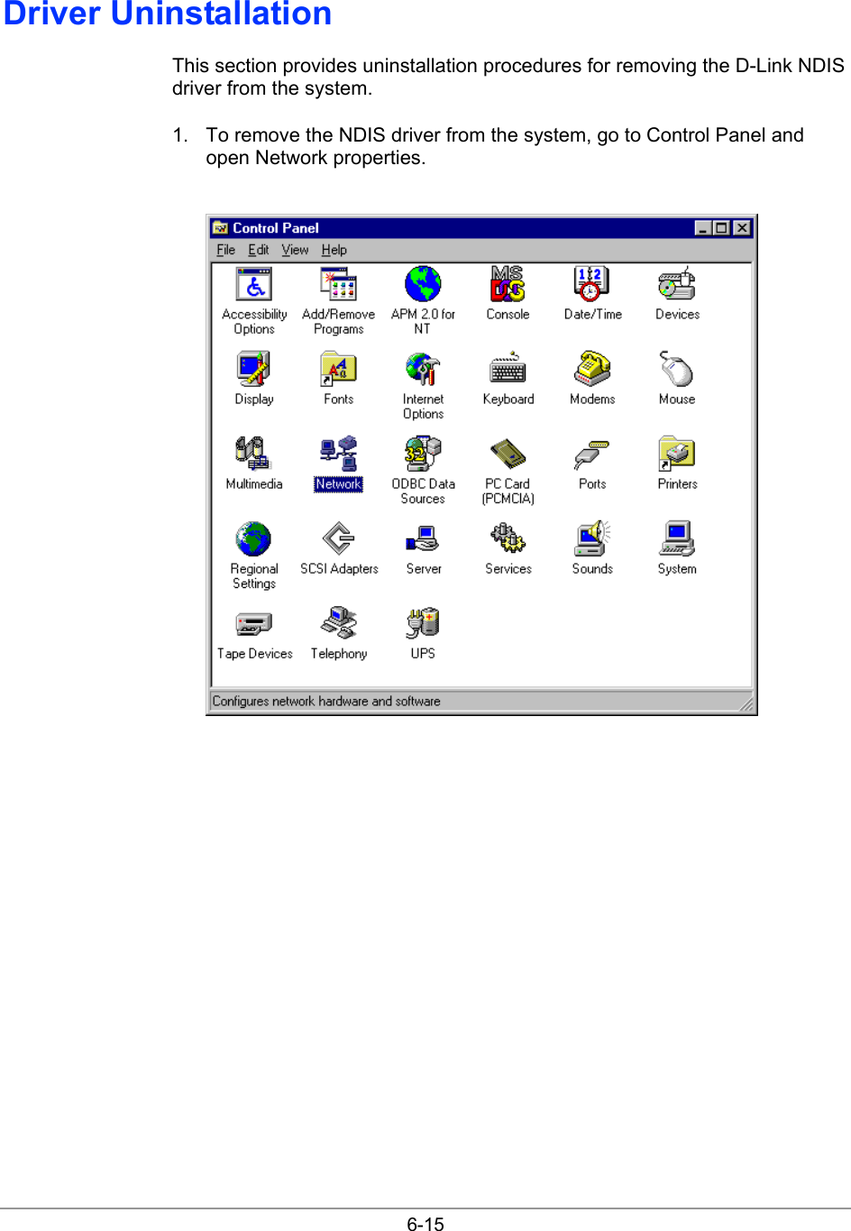
User Manual
Discussion / Help
Navigation