D Link 2001120011-1 Wireless LAN CardBus PC Card User Manual 2nd Revised UsersGuide
D Link Corporation Wireless LAN CardBus PC Card 2nd Revised UsersGuide
D Link >
Revision 3 of Users Manual

i
DW-690 & DWL-A650
5GHz Wireless Cardbus Card
User’s Manual
First Edition (December, 2001)
6DWLA650..01
Wichtige Sicherheitshinweise
1. Bitte lesen Sie sich diese Hinweise sorgfältig durch.
2. Heben Sie diese Anleitung für den spätern Gebrauch auf.
3. Vor jedem Reinigen ist das Gerät vom Stromnetz zu trennen. Vervenden Sie keine Flüssig- oder
Aerosolreiniger. Am besten dient ein angefeuchtetes Tuch zur Reinigung.
4. Um eine Beschädigung des Gerätes zu vermeiden sollten Sie nur Zubehörteile verwenden, die vom Hersteller
zugelassen sind.
5. Das Gerät is vor Feuchtigkeit zu schützen.
6. Bei der Aufstellung des Gerätes ist auf sichern Stand zu achten. Ein Kippen oder Fallen könnte Verletzungen
hervorrufen. Verwenden Sie nur sichere Standorte und beachten Sie die Aufstellhinweise des Herstellers.
7. Die Belüftungsöffnungen dienen zur Luftzirkulation die das Gerät vor Überhitzung schützt. Sorgen Sie dafür,
daß diese Öffnungen nicht abgedeckt werden.
8. Beachten Sie beim Anschluß an das Stromnetz die Anschlußwerte.
9. Die Netzanschlußsteckdose muß aus Gründen der elektrischen Sicherheit einen Schutzleiterkontakt haben.
10. Verlegen Sie die Netzanschlußleitung so, daß niemand darüber fallen kann. Es sollete auch nichts auf der
Leitung abgestellt werden.
11. Alle Hinweise und Warnungen die sich am Geräten befinden sind zu beachten.
12. Wird das Gerät über einen längeren Zeitraum nicht benutzt, sollten Sie es vom Stromnetz trennen. Somit
wird im Falle einer Überspannung eine Beschädigung vermieden.
13. Durch die Lüftungsöffnungen dürfen niemals Gegenstände oder Flüssigkeiten in das Gerät gelangen. Dies
könnte einen Brand bzw. Elektrischen Schlag auslösen.
14. Öffnen Sie niemals das Gerät. Das Gerät darf aus Gründen der elektrischen Sicherheit nur von authorisiertem
Servicepersonal geöffnet werden.
15. Wenn folgende Situationen auftreten ist das Gerät vom Stromnetz zu trennen und von einer qualifizierten
Servicestelle zu überprüfen:
a – Netzkabel oder Netzstecker sint beschädigt.
b – Flüssigkeit ist in das Gerät eingedrungen.
c – Das Gerät war Feuchtigkeit ausgesetzt.
d – Wenn das Gerät nicht der Bedienungsanleitung ensprechend funktioniert oder Sie mit Hilfe dieser Anleitung
keine Verbesserung erzielen.
e – Das Gerät ist gefallen und/oder das Gehäuse ist beschädigt.
f – Wenn das Gerät deutliche Anzeichen eines Defektes aufweist.
16. Bei Reparaturen dürfen nur Orginalersatzteile bzw. den Orginalteilen entsprechende Teile verwendet werden.
Der Einsatz von ungeeigneten Ersatzteilen kann eine weitere Beschädigung hervorrufen.

iii
17. Wenden Sie sich mit allen Fragen die Service und Repartur betreffen an Ihren Servicepartner. Somit stellen
Sie die Betriebssicherheit des Gerätes sicher.
18. Zum Netzanschluß dieses Gerätes ist eine geprüfte Leitung zu verwenden, Für einen Nennstrom bis 6A und
einem Gerätegewicht großer 3kg ist eine Leitung nicht leichter als H05VV-F, 3G, 0.75mm2 einzusetzen
Limited Warranty
Hardware:
D-LINK WARRANTS EACH OF ITS HARDWARE PRODUCTS TO BE FREE FROM DEFECTS IN WORKMANSHIP AND
MATERIALS UNDER NORMAL USE AND SERVICE FOR A PERIOD COMMENCING ON THE DATE OF PURCHASE FROM
D-LINK OR ITS AUTHORIZED RESELLER AND EXTENDING FOR THE LENGTH OF TIME STIPULATED BY THE
AUTHORIZED RESELLER OR D-LINK BRANCH OFFICE NEAREST TO THE PLACE OF PURCHASE.
THIS WARRANTY APPLIES ON THE CONDITION THAT THE PRODUCT REGISTRATION CARD IS FILLED OUT AND
RETURNED TO A D-LINK OFFICE WITHIN NINETY (90) DAYS OF PURCHASE. A LIST OF D-LINK OFFICES IS
PROVIDED AT THE BACK OF THIS MANUAL, TOGETHER WITH A COPY OF THE REGISTRATION CARD.
IF THE PRODUCT PROVES DEFECTIVE WITHIN THE APPLICABLE WARRANTY PERIOD, D-LINK WILL PROVIDE
REPAIR OR REPLACEMENT OF THE PRODUCT. D-LINK SHALL HAVE THE SOLE DISCRETION WHETHER TO REPAIR
OR REPLACE, AND REPLACEMENT PRODUCT MAY BE NEW OR RECONDITIONED. REPLACEMENT PRODUCT
SHALL BE OF EQUIVALENT OR BETTER SPECIFICATIONS, RELATIVE TO THE DEFECTIVE PRODUCT, BUT NEED NOT
BE IDENTICAL. ANY PRODUCT OR PART REPAIRED BY D-LINK PURSUANT TO THIS WARRANTY SHALL HAVE A
WARRANTY PERIOD OF NOT LESS THAN 90 DAYS, FROM DATE OF SUCH REPAIR, IRRESPECTIVE OF ANY EARLIER
EXPIRATION OF ORIGINAL WARRANTY PERIOD. WHEN D-LINK PROVIDES REPLACEMENT, THEN THE DEFECTIVE
PRODUCT BECOMES THE PROPERTY OF D-LINK.
WARRANTY SERVICE MAY BE OBTAINED BY CONTACTING A D-LINK OFFICE WITHIN THE APPLICABLE
WARRANTY PERIOD, AND REQUESTING A RETURN MATERIAL AUTHORIZATION (RMA) NUMBER. IF A
REGISTRATION CARD FOR THE PRODUCT IN QUESTION HAS NOT BEEN RETURNED TO D-LINK , THEN A PROOF OF
PURCHASE (SUCH AS A COPY OF THE DATED PURCHASE INVOICE) MUST BE PROVIDED. IF PURCHASER’S
CIRCUMSTANCES REQUIRE SPECIAL HANDLING OF WARRANTY CORRECTION, THEN AT THE TIME OF
REQUESTING RMA NUMBER, PURCHASER MAY ALSO PROPOSE SPECIAL PROCEDURE AS MAY BE SUITABLE TO THE
CASE.
AFTER AN RMA NUMBER IS ISSUED, THE DEFECTIVE PRODUCT MUST BE PACKAGED SECURELY IN THE ORIGINAL
OR OTHER SUITABLE SHIPPING PACKAGE TO ENSURE THAT IT WILL NOT BE DAMAGED IN TRANSIT, AND THE
RMA NUMBER MUST BE PROMINENTLY MARKED ON THE OUTSIDE OF THE PACKAGE. THE PACKAGE MUST BE
MAILED OR OTHERWISE SHIPPED TO D-LINK WITH ALL COSTS OF MAILING/SHIPPING/INSURANCE PREPAID. D-
LINK SHALL NEVER BE RESPONSIBLE FOR ANY SOFTWARE, FIRMWARE, INFORMATION, OR MEMORY DATA OF
PURCHASER CONTAINED IN, STORED ON, OR INTEGRATED WITH ANY PRODUCT RETURNED TO D-LINK
PURSUANT TO THIS WARRANTY.
ANY PACKAGE RETURNED TO D-LINK WITHOUT AN RMA NUMBER WILL BE REJECTED AND SHIPPED BACK TO
PURCHASER AT PURCHASER’S EXPENSE, AND D-LINK RESERVES THE RIGHT IN SUCH A CASE TO LEVY A
REASONABLE HANDLING CHARGE IN ADDITION MAILING OR SHIPPING COSTS.
Software:
WARRANTY SERVICE FOR SOFTWARE PRODUCTS MAY BE OBTAINED BY CONTACTING A D-LINK OFFICE WITHIN
THE APPLICABLE WARRANTY PERIOD. A LIST OF D-LINK OFFICES IS PROVIDED AT THE BACK OF THIS MANUAL,
TOGETHER WITH A COPY OF THE REGISTRATION CARD. IF A REGISTRATION CARD FOR THE PRODUCT IN
QUESTION HAS NOT BEEN RETURNED TO A D-LINK OFFICE, THEN A PROOF OF PURCHASE (SUCH AS A COPY OF
THE DATED PURCHASE INVOICE) MUST BE PROVIDED WHEN REQUESTING WARRANTY SERVICE. THE TERM
“PURCHASE” IN THIS SOFTWARE WARRANTY REFERS TO THE PURCHASE TRANSACTION AND RESULTING
LICENSE TO USE SUCH SOFTWARE.
D-LINK WARRANTS THAT ITS SOFTWARE PRODUCTS WILL PERFORM IN SUBSTANTIAL CONFORMANCE WITH THE
APPLICABLE PRODUCT DOCUMENTATION PROVIDED BY D-LINK WITH SUCH SOFTWARE PRODUCT, FOR A PERIOD
OF NINETY (90) DAYS FROM THE DATE OF PURCHASE FROM D-LINK OR ITS AUTHORIZED RESELLER. D-LINK
WARRANTS THE MAGNETIC MEDIA, ON WHICH D-LINK PROVIDES ITS SOFTWARE PRODUCT, AGAINST FAILURE
DURING THE SAME WARRANTY PERIOD. THIS WARRANTY APPLIES TO PURCHASED SOFTWARE, AND TO
REPLACEMENT SOFTWARE PROVIDED BY D-LINK PURSUANT TO THIS WARRANTY, BUT SHALL NOT APPLY TO
ANY UPDATE OR REPLACEMENT WHICH MAY BE PROVIDED FOR DOWNLOAD VIA THE INTERNET, OR TO ANY
UPDATE WHICH MAY OTHERWISE BE PROVIDED FREE OF CHARGE.
D-LINK SOLE OBLIGATION UNDER THIS SOFTWARE WARRANTY SHALL BE TO REPLACE ANY DEFECTIVE
SOFTWARE PRODUCT WITH PRODUCT WHICH SUBSTANTIALLY CONFORMS TO D-LINK ’S APPLICABLE PRODUCT
DOCUMENTATION. PURCHASER ASSUMES RESPONSIBILITY FOR THE SELECTION OF APPROPRIATE APPLICATION
AND SYSTEM/PLATFORM SOFTWARE AND ASSOCIATED REFERENCE MATERIALS. D-LINK MAKES NO WARRANTY
THAT ITS SOFTWARE PRODUCTS WILL WORK IN COMBINATION WITH ANY HARDWARE, OR ANY APPLICATION
OR SYSTEM/PLATFORM SOFTWARE PRODUCT PROVIDED BY ANY THIRD PARTY, EXCEPTING ONLY SUCH
PRODUCTS AS ARE EXPRESSLY REPRESENTED, IN D-LINK ’S APPLICABLE PRODUCT DOCUMENTATION AS BEING
COMPATIBLE. D-LINK ’S OBLIGATION UNDER THIS WARRANTY SHALL BE A REASONABLE EFFORT TO PROVIDE
COMPATIBILITY, BUT D-LINK SHALL HAVE NO OBLIGATION TO PROVIDE COMPATIBILITY WHEN THERE IS FAULT
IN THE THIRD-PARTY HARDWARE OR SOFTWARE. D-LINK MAKES NO WARRANTY THAT OPERATION OF ITS
SOFTWARE PRODUCTS WILL BE UNINTERRUPTED OR ABSOLUTELY ERROR-FREE, AND NO WARRANTY THAT ALL
DEFECTS IN THE SOFTWARE PRODUCT, WITHIN OR WITHOUT THE SCOPE OF D-LINK ’S APPLICABLE PRODUCT
DOCUMENTATION, WILL BE CORRECTED.

v
D-Link Offices for Registration and Warranty Service
THE PRODUCT’S REGISTRATION CARD, PROVIDED AT THE BACK OF THIS MANUAL, MUST BE SENT TO A D-LINK OFFICE.
TO OBTAIN AN RMA NUMBER FOR WARRANTY SERVICE AS TO A HARDWARE PRODUCT, OR TO OBTAIN WARRANTY
SERVICE AS TO A SOFTWARE PRODUCT, CONTACT THE D-LINK OFFICE NEAREST YOU. AN ADDRESS/TELEPHONE/FAX/E-
MAIL/WEB SITE LIST OF D-LINK OFFICES IS PROVIDED IN THE BACK OF THIS MANUAL.
LIMITATION OF WARRANTIES
IF THE D-LINK PRODUCT DOES NOT OPERATE AS WARRANTED ABOVE, THE CUSTOMER’S SOLE REMEDY SHALL
BE, AT D-LINK ’S OPTION, REPAIR OR REPLACEMENT. THE FOREGOING WARRANTIES AND REMEDIES ARE
EXCLUSIVE AND ARE IN LIEU OF ALL OTHER WARRANTIES, EXPRESSED OR IMPLIED, EITHER IN FACT OR BY
OPERATION OF LAW, STATUTORY OR OTHERWISE, INCLUDING WARRANTIES OF MERCHANTABILITY AND
FITNESS FOR A PARTICULAR PURPOSE. D-LINK NEITHER ASSUMES NOR AUTHORIZES ANY OTHER PERSON TO
ASSUME FOR IT ANY OTHER LIABILITY IN CONNECTION WITH THE SALE, INSTALLATION MAINTENANCE OR USE
OF D-LINK ’S PRODUCTS
D-LINK SHALL NOT BE LIABLE UNDER THIS WARRANTY IF ITS TESTING AND EXAMINATION DISCLOSE THAT THE
ALLEGED DEFECT IN THE PRODUCT DOES NOT EXIST OR WAS CAUSED BY THE CUSTOMER’S OR ANY THIRD
PERSON’S MISUSE, NEGLECT, IMPROPER INSTALLATION OR TESTING, UNAUTHORIZED ATTEMPTS TO REPAIR, OR
ANY OTHER CAUSE BEYOND THE RANGE OF THE INTENDED USE, OR BY ACCIDENT, FIRE, LIGHTNING OR OTHER
HAZARD.
LIMITATION OF LIABILITY
IN NO EVENT WILL D-LINK BE LIABLE FOR ANY DAMAGES, INCLUDING LOSS OF DATA, LOSS OF PROFITS, COST OF
COVER OR OTHER INCIDENTAL, CONSEQUENTIAL OR INDIRECT DAMAGES ARISING OUT THE INSTALLATION,
MAINTENANCE, USE, PERFORMANCE, FAILURE OR INTERRUPTION OF A D- LINK PRODUCT, HOWEVER CAUSED
AND ON ANY THEORY OF LIABILITY. THIS LIMITATION WILL APPLY EVEN IF D-LINK HAS BEEN ADVISED OF THE
POSSIBILITY OF SUCH DAMAGE.
IF YOU PURCHASED A D-LINK PRODUCT IN THE UNITED STATES, SOME STATES DO NOT ALLOW THE LIMITATION
OR EXCLUSION OF LIABILITY FOR INCIDENTAL OR CONSEQUENTIAL DAMAGES, SO THE ABOVE LIMITATION MAY
NOT APPLY TO YOU.
Trademarks
Copyright
2000 D-Link Corporation.
Contents subject to change without prior notice.
D-Link is a registered trademark of D-Link Corporation/D-Link Systems, Inc.
All other trademarks belong to their respective proprietors.
Copyright Statement
No part of this publication may be reproduced in any form or by any means or used to make any derivative
such as translation, transformation, or adaptation without permission from D-Link Corporation/D-Link
Systems Inc., as stipulated by the United States Copyright Act of 1976
vii
FCC Warning
This device complies with part 15 of the FCC Rules. Operation is subject to the following two conditions: (1) This
device may not cause harmful interference, and (2) this device must accept any interference received, including
interference that may cause undesired operation.
This equipment has been tested and found to comply with the limits for a Class B digital device, pursuant to part
15 of the FCC Rules. These limits are designed to provide reasonable protection against harmful interference in a
residential installation. This generates, uses and can radiate radio frequency energy and, if not installed and used
in accordance with the instructions, may cause harmful interference to radio communications. However, there is
no guarantee that interference will not occur in a particular installation. If this equipment does cause harmful
interference to radio or television reception, which can be determined by turning equipment off and on, the user is
encouraged to try to correct the interference by one or more of the following measures:
Reorient or relocate the receiving antenna.
Increase the separation between the equipment and receiver.
Connect the equipment into an outlet on a circuit different from that to which the
receiver is connected.
Consult the dealer or an experienced radio/TV technician for help.
CE Mark Warning
This is a Class B product. In a domestic environment, this product may cause radio interference in which case
the user may be required to take adequate measures.
VCCI Class B Warning

ix
Notices
NOTE: This message denotes neutral or positive information that calls out
important points to the text. A note provides information that may apply only
in special cases.
CAUTION: Cautions call special attention to hazards that can cause system
damage or data corruption, to a lesser degree than warnings.
WARNING: Warnings call special attention to hazards that can cause
system damage, data corruption, personal injury, or death.
Statements:
Warning
To ensure compliance with FCC RF exposure requirements, the antenna used for
this device must be installed to provide a separation distance of at least 20 cm
from all persons and must not be co-located or operating in conjunction with any
other antenna or radio transmitter. Installers and end-users must follow the
installation instructions provided in this user guide.
1. Modifications to this device, unless expressly approved by D-Link, could void the user’s
right to operate this equipment.
2. The frequency band 5150-5250 MHz is only for indoor usage to reduce potential for harmful
interference to co-channel Mobile Satellite systems. The device can only be operated as an
indoor unit.
3. High power radars are allocated as primary users (meaning they have priority) of 5250-
5350 MHz and 5650-5850 MHz and these radars could cause interference and/or damage
to LELAN devices used in Canada.
4. Radio Frequency interference requirements: The device is restricted to indoor use only.
FCC requires this product to be used indoors due to its operation in the frequency range
5.15 to 5.25 GHz.

Contents
List of Figures .........................................................xv
List of Tables.........................................................xvii
Preface ....................................................................xix
About this Document ....................................................................................xix
Audience ...................................................................................................... xx
Additional Resources.................................................................................... xx
1 Introduction............................................................1-1
Package Contents .......................................................................................1-1
System Requirements .................................................................................1-2
2 Windows 2000 ........................................................2-1
Driver Installation (First-time Install) ............................................................2-1
Driver Installation (Previous Driver Installed)...............................................2-5
Driver Uninstallation ..................................................................................2-14
Device Configuration .................................................................................2-17
Infrastructure Mode .............................................................................2-22
Ad Hoc Mode.......................................................................................2-23
TCP/IP Setup ......................................................................................2-24

3 Windows Millennium Edition ............................... 3-1
Driver Installation.........................................................................................3-1
Driver Uninstallation ....................................................................................3-5
Device Configuration ...................................................................................3-7
Infrastructure Mode ...............................................................................3-9
Ad Hoc Mode.......................................................................................3-10
TCP/IP Configuration...........................................................................3-12
4 Windows 98 Second Edition ................................ 4-1
Driver Installation.........................................................................................4-1
Driver Uninstallation ....................................................................................4-5
Device Configuration ...................................................................................4-8
Infrastructure Mode ...............................................................................4-9
Ad Hoc Mode.......................................................................................4-11
TCP/IP Setup ......................................................................................4-13
5 Windows XP........................................................... 5-1
Driver Installation (First-time Install) ............................................................5-1
Driver Uninstallation ....................................................................................5-6
Device Configuration .................................................................................5-10
Infrastructure Mode .............................................................................5-12
Ad Hoc Mode.......................................................................................5-13
TCP/IP Setup ......................................................................................5-15
Windows XP Wireless Network Configuration ...........................................5-20
Infrastructure Mode .............................................................................5-22
Ad hoc mode .......................................................................................5-24
Connect to an Available Wireless Network..........................................5-26
6 Windows NT 4.0..................................................... 6-1
Driver Installation and TCP/IP Setup ...........................................................6-1
Device Configuration ...................................................................................6-7

Infrastructure Mode ...............................................................................6-8
Ad Hoc Mode.......................................................................................6-11
Verify Connection ................................................................................ 6-13
Driver Uninstallation ..................................................................................6-15
7 LinkMon ..................................................................7-1
Installation ...................................................................................................7-1
Features ......................................................................................................7-5
8 RFSilent ..................................................................8-1
System Requirements .................................................................................8-1
Windows 98SE Environment .................................................................8-1
RFSilent Setup ............................................................................................8-2
Operation.....................................................................................................8-2
9 Troubleshooting ....................................................9-1
A Channel and Data Rate Selection ....................A-9-2


List of Figures
Figure 2-1. Infrastructure Mode.............................................................. 2-17
Figure 2-2. Ad Hoc Mode ....................................................................... 2-18
Figure 8-1. RFSilent Icon ......................................................................... 8-2
Figure 8-2. RFSilent Menu Selections...................................................... 8-2


List of Tables
Table 8-1. RFSilent Menu Descriptions .................................................. 8-3


Preface
This user’s guide provides the necessary information for first-time users to
successfully install the D-Link Network Driver Interface Specification (NDIS)
driver, for the purpose of evaluating and/or operating the D-Link DWL-A650
Station Reference Design in a Microsoft Windows environment. This guide
also provides information for users who wish to upgrade the D-Link NDIS
driver from previous releases.
This guide describes the steps required to install NDIS drivers for the D-Link
DWL-A650 Wireless Network Adapter in Windows 2000, Windows Millennium
Edition, Windows 98 Second Edition, Windows XP, and Windows NT 4.0.
This guide also includes detailed instructions for configuring the PC Card
device, or IEEE 802.11a station (STA), to interact with an access point (AP)
in infrastructure mode and with other STAs in ad hoc mode. Instructions for
installing or upgrading the diagnostic utility LinkMon are also included. You
should also read this before proceeding to install the D-Link DWL-A650
Wireless Network Adapter and NDIS driver in the targeted operating system
(OS) environment.
About this Document
The document consists of the following chapters and appendixes:
Chapter 1 Introduction—Hardware, Software, and System
Requirements needed to setup D-Link DWL-A650 Station
Reference Design.
Chapter 2 Windows 2000—Installation/Uninstallation Procedures and
Device/Network Configurations for Windows 2000.
Chapter 3 Windows Millennium Edition—Installation/Uninstallation
Procedures and Device/Network Configurations for Windows
Millennium Edition.
Chapter 4 Windows 98 Second Edition—Installation/Uninstallation
Procedures and Device/Network Configurations for Windows
98 Second Edition.
Chapter 5 Windows XP—Installation/Uninstallation Procedures and
Device/Network Configurations for Windows XP.

Chapter 6 Windows NT 4.0—Installation/Uninstallation Procedures
and Device/Network Configurations for Windows NT 4.0.
Chapter 7 LinkMon—Graphical User Interface for Operational Status
and Statistics of D-Link DWL-A650 Station Reference
Design.
Chapter 8 RFSilent—RFSilent application that allows you to enable or
disable the RF Signal (radio) on all D-Link STA Reference
Designs.
Chapter 9 Troubleshooting—Hints on fixing common
Installation/Uninstallation and Device/Network
Configurations issues.
Appendix A Channel and Data Rate Selection—Describes how to
select Fixed Data Rate and/or Channel Frequency for
specific testing.
Audience
This document is intended for D-Link customers who wish to install and
evaluate the D-Link DWL-A650 Station Reference Design in the supported
Microsoft Windows environments.
Additional Resources
D-Link STA Reference Design hardware, software, and documentation
contain proprietary information of D-Link Communications, Inc., and are
provided under a license agreement containing restrictions on use and
disclosure, and are also protected by copyright law. Reverse engineering of
this hardware, software, or documentation is prohibited.
The following resources should be referenced regarding topics that are not
addressed in this document:
AR5110 Radio-on-a-Chip for 5-GHz Wireless LANs data sheet
AR5210 MAC/Baseband Processor for IEEE 802.11a 5-GHz Wireless
LAN data sheet
AP User’s Guide
STA Reference Design Functional Specification

1-1
1
Introduction
The D-Link DWL-A650 Wireless Network Adapter is an IEEE 802.11a two-chip
solution reference design based on the Atheros AR5110 and AR5210 chipset.
This reference design implements a half-duplex, Orthogonal Frequency Division
Multiplexing (OFDM) baseband processor supporting all IEEE 802.11a data rates
(6 to 54 Mbps). It also supports the D-Link Turbo ModeTM supporting data rates
up to 108 Mbps. The host interface is compatible with the PC Card 7.1 standard.
You can find information regarding the D-Link Station Reference Designs in the
detailed D-Link STA Reference Design Functional Specification.
Package Contents
Make sure the following materials are available before you begin:
One 802.11a PCI Card
One Installation CD-ROM containing software and utilities and this user’s
guide
One 802.11a PCI Card Quick Start Guide
One warranty registration card

1-2
System Requirements
Laptop PC containing:
− 32-bit CardBus slot (or Desktop PC with PC Card-PCI adapter)
− 32 MB memory or greater
− 300 MHz processor or higher
Microsoft Windows 2000/Windows Millennium Edition/Windows 98
Second Edition/Windows XP/Windows NT 4.0 (with Service Pack 6)
2-1
2
Windows 2000
Driver Installation (First-time Install)
Insert the D-Link DWL-A650 Wireless Network Adapter into a 32-bit CardBus
slot and follow these steps to install the NDIS driver:
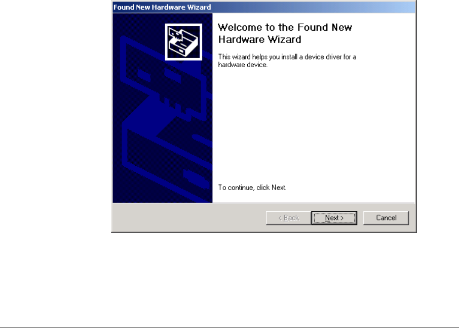
1. Wait for the following dialog box to display, and click Next to continue.
2-2
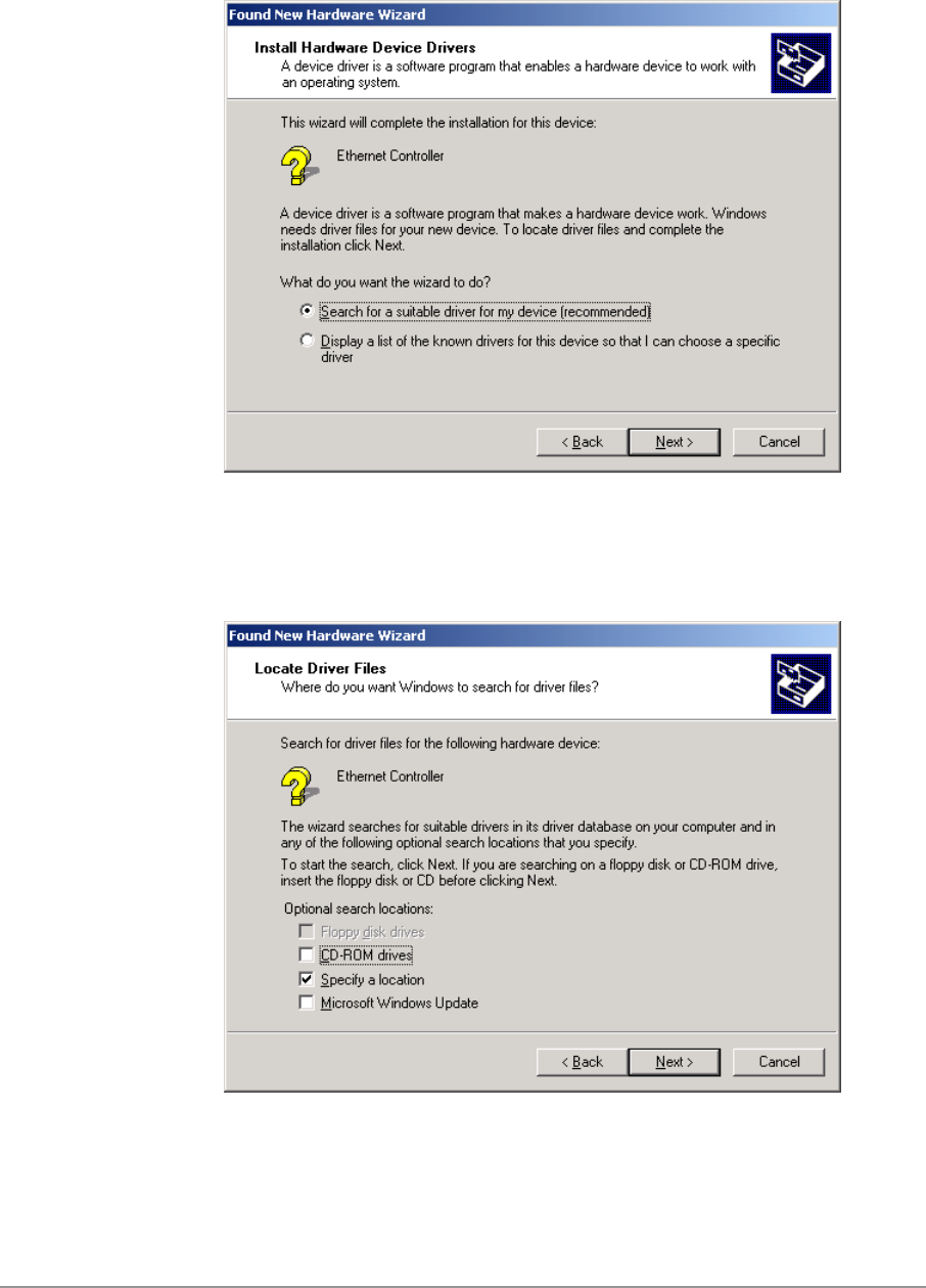
2. Choose “Search for a suitable driver for my device (recommended),” and
click Next.
3. Insert the installation CD in your CD-ROM drive. Choose “Specify a
location” under “Optional search locations,” and click Next to continue.
2-3
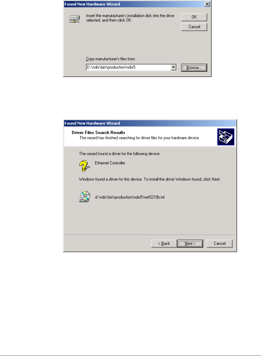
4. Browse to the location where the NDIS driver is located (assuming D is
the CD-ROM drive), the default folder is D:\ndis\bin\production\ndis5.
Click OK to continue.
5. When you find the D-Link driver installation file (net5210b.inf), click Next
to continue.
2-4
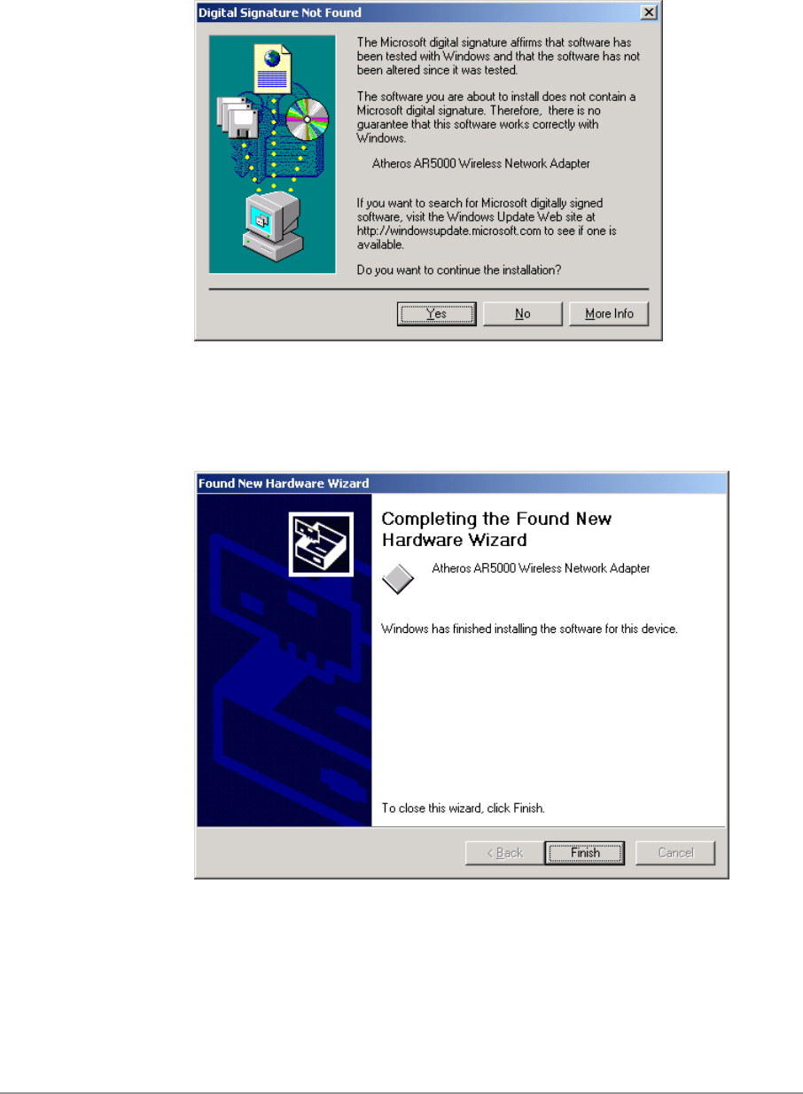
6. The D-Link NDIS evaluation driver currently does not have a digital
signature from Microsoft. Therefore, Windows 2000 shows a warning
message. Click Yes to proceed with driver installation.
7. Click Finish to complete the driver installation. See Section “Device
Configuration” for the device configuration.
2-5
Driver Installation (Previous Driver Installed)
If the system already has a previous release of the D-Link NDIS installed,
Windows does not prompt for the device driver when the WLAN Card is
inserted. Follow the steps below to update the NDIS driver:
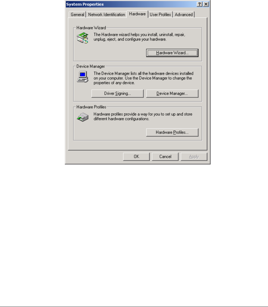
1. Start System Properties from Control Panel. Under Hardware tab, click
Device Manager.
2-6
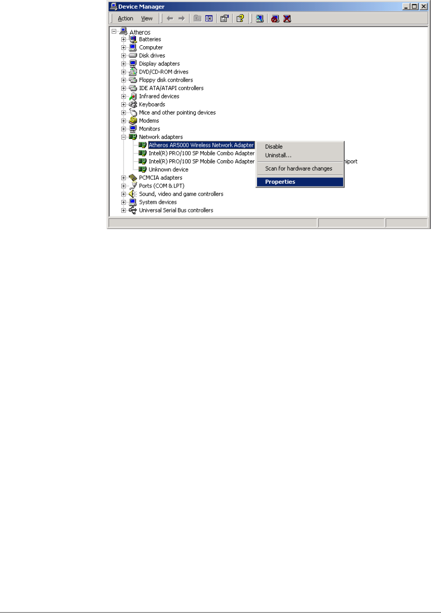
2. Within Device Manager, right-click “D-Link DWL-A650 Wireless Network
Adapter” under “Network adapters” device node, and click Properties.
2-7
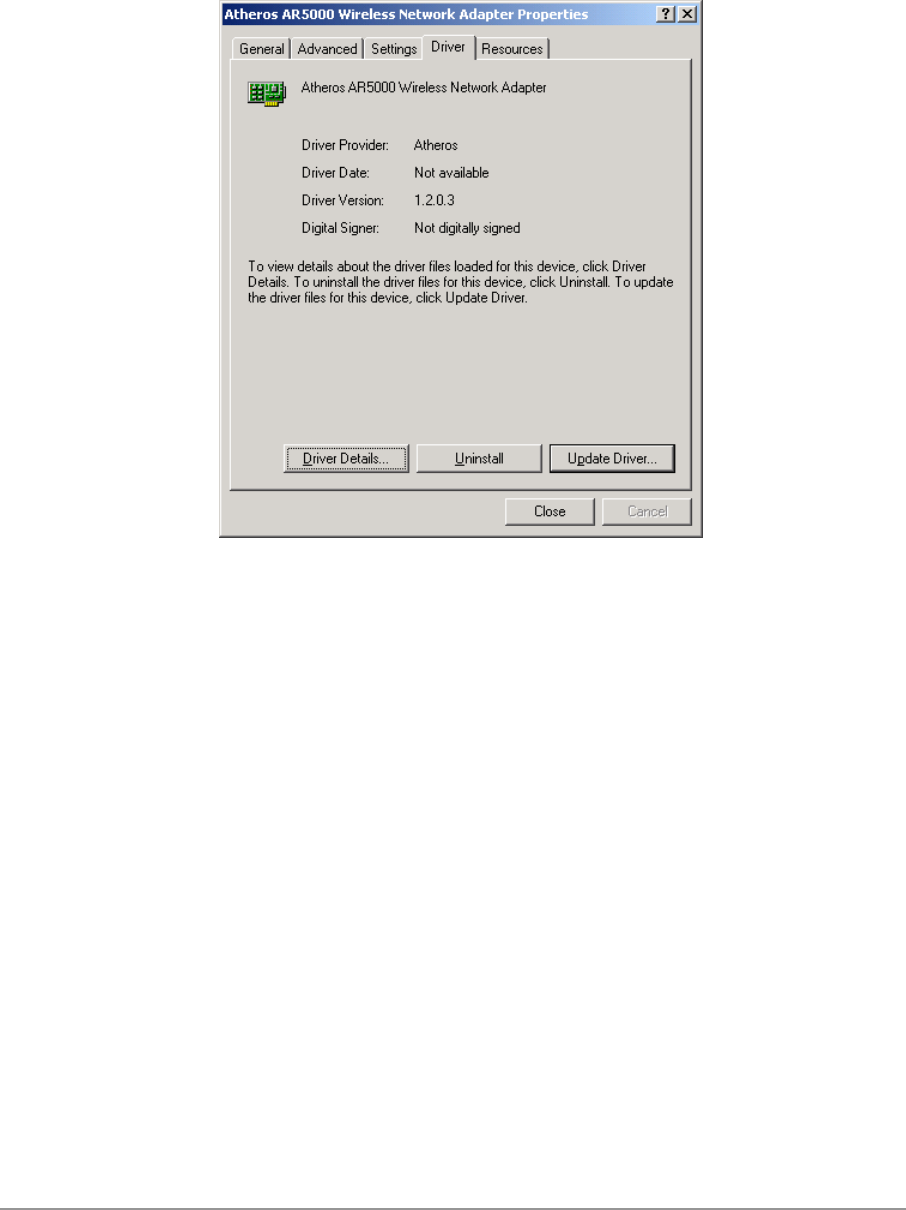
3. Click “Update Driver…” from the Driver tab. Note the Driver Version that
you are updating from. You may need to verify this field again after driver
update completes to make sure Release 1.3 driver has been updated
correctly.
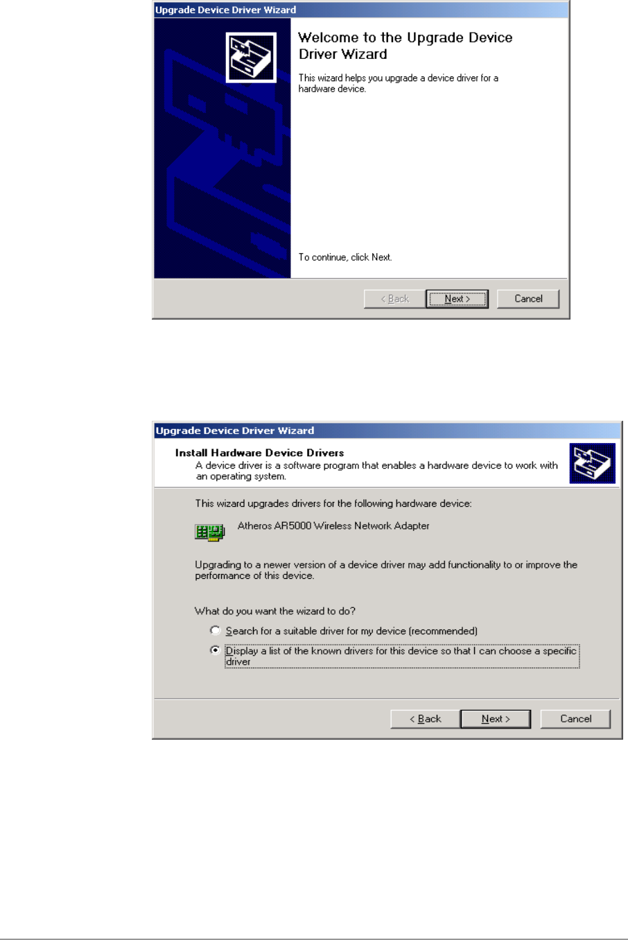
4. Click Next to continue.
2-8
5. Choose “Display a list of the known drivers for this device so that I can
choose a specific driver,” and click Next to continue.
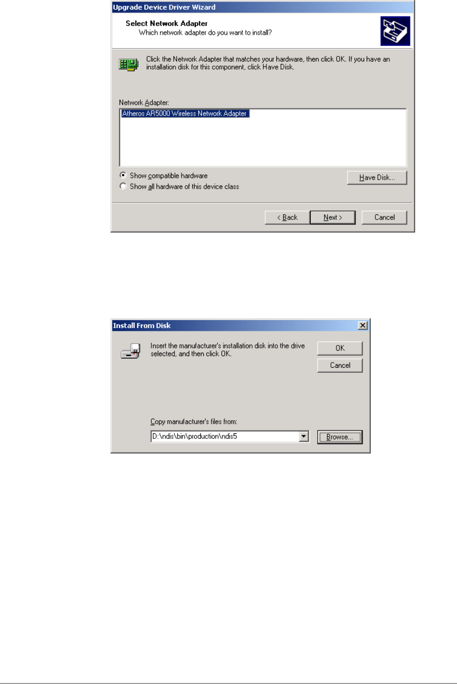
6. Insert the Release 1.3 CD into your CD-ROM drive. Click “Have Disk…”
to continue.
2-9
7. Browse to the location where the NDIS driver is located (assuming D is
the CD-ROM drive), the default folder is “D:\ndis\bin\production\ndis5”.
Click OK to continue.
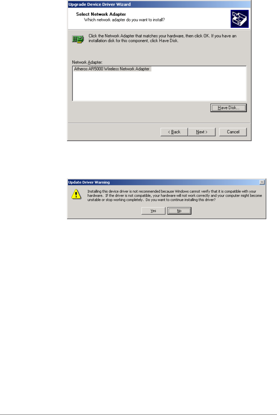
8. Select “D-Link DWL-A650 Wireless Network Adapter” from the list and
click Next to continue.
2-10
9. Click Yes to continue when Windows displays the warning message.
2-11
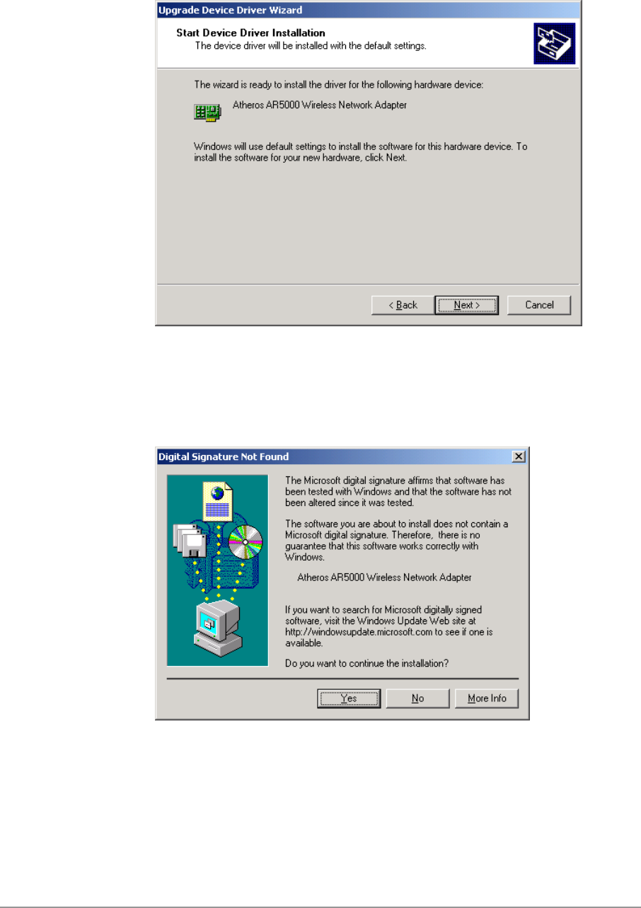
10. Click Next to proceed with installation.
11. The D-Link NDIS evaluation driver currently does not have a digital
signature from Microsoft. Therefore, Windows 2000 shows a warning
message. Click Yes to proceed with driver installation.
2-12
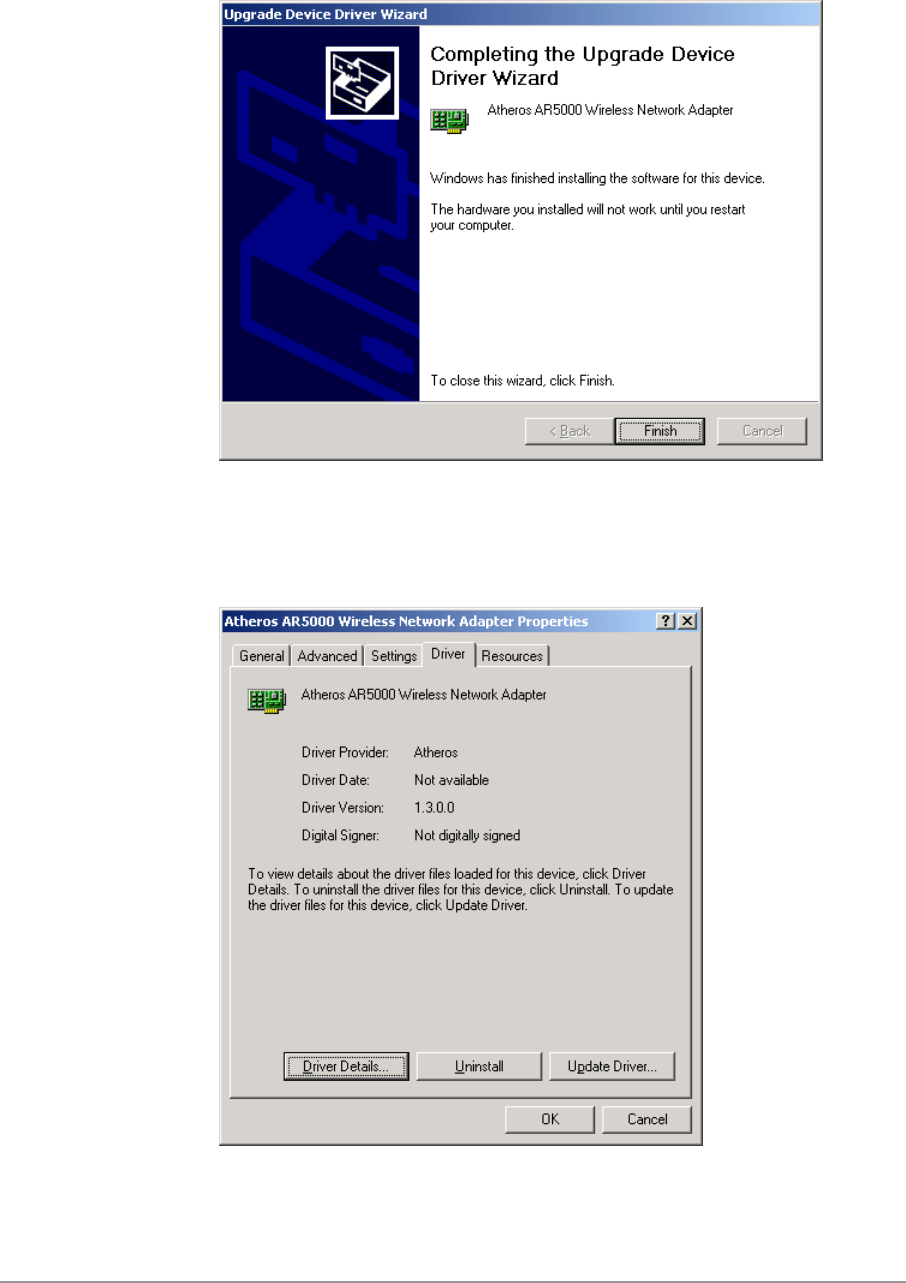
12. Click Finish.
13. Note that Driver Version should display 1.3 as the major revision number.
Click OK to continue.
2-13
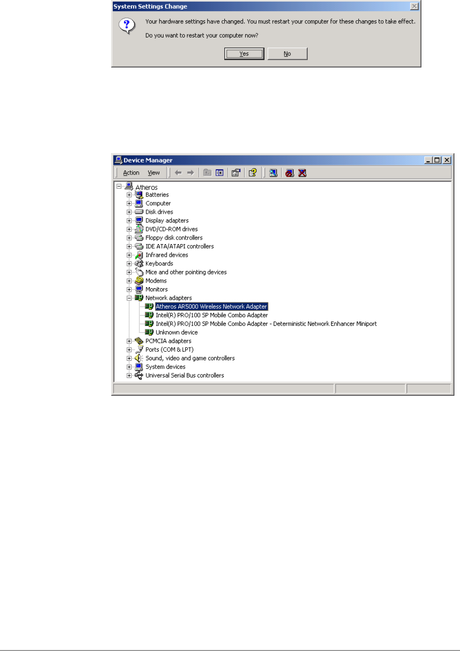
14. Click Yes to restart system.
15. After system restarts, the “D-Link DWL-A650 Wireless Network Adapter”
now displays under “Network adapters” in the Device Manager. Proceed
to Section “Device Configuration” for device configuration information.
2-14
Driver Uninstallation
This section provides information about uninstallation procedures required for
upgrading the NDIS driver from previous D-Link software releases. If the
system does not have previously installed versions of the NDIS driver and
you wish to remove the newly installed driver from the system, proceed to
Step 4.
The NDIS driver since Release 1.0 no longer leverages the Transport Driver
Interface (TDI) protocol to provide the LinkMon programming interface. The
TDI protocol should be uninstalled. Follow these steps to uninstall the TDI
protocol:
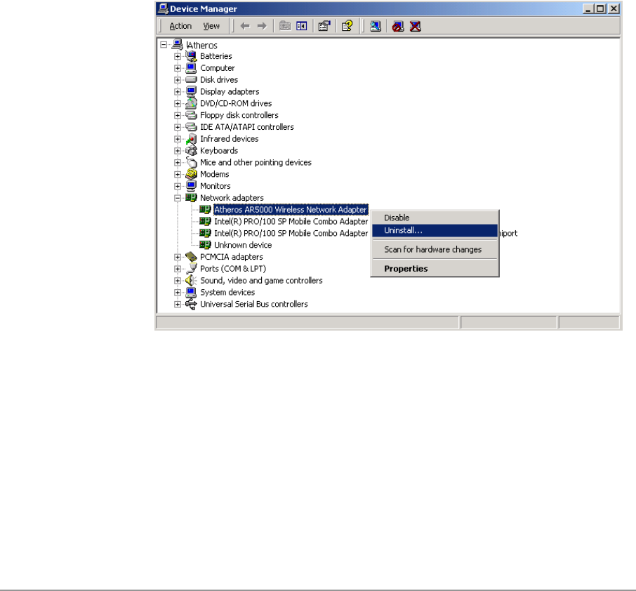
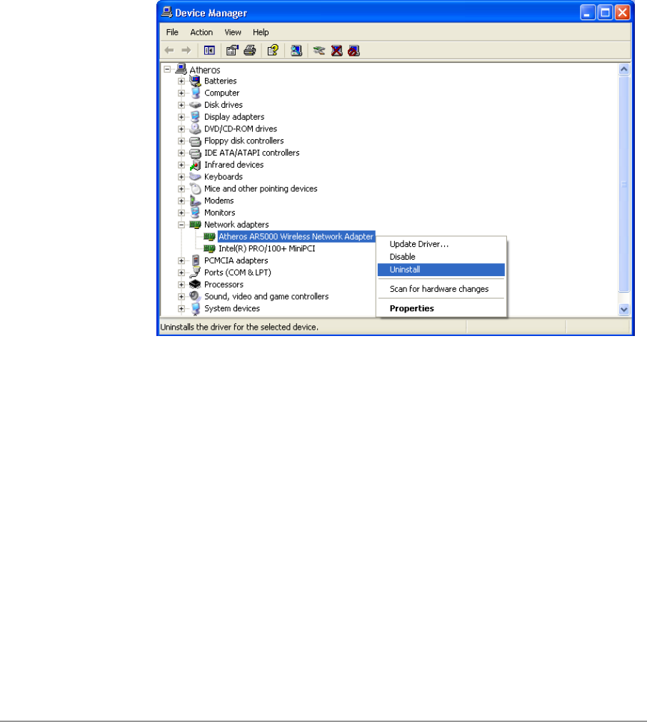
1. To remove the NDIS driver from the OS, go to Device Manager, right-
click “D-Link DWL-A650 Wireless Network Adapter,” and choose
Uninstall.
2-15
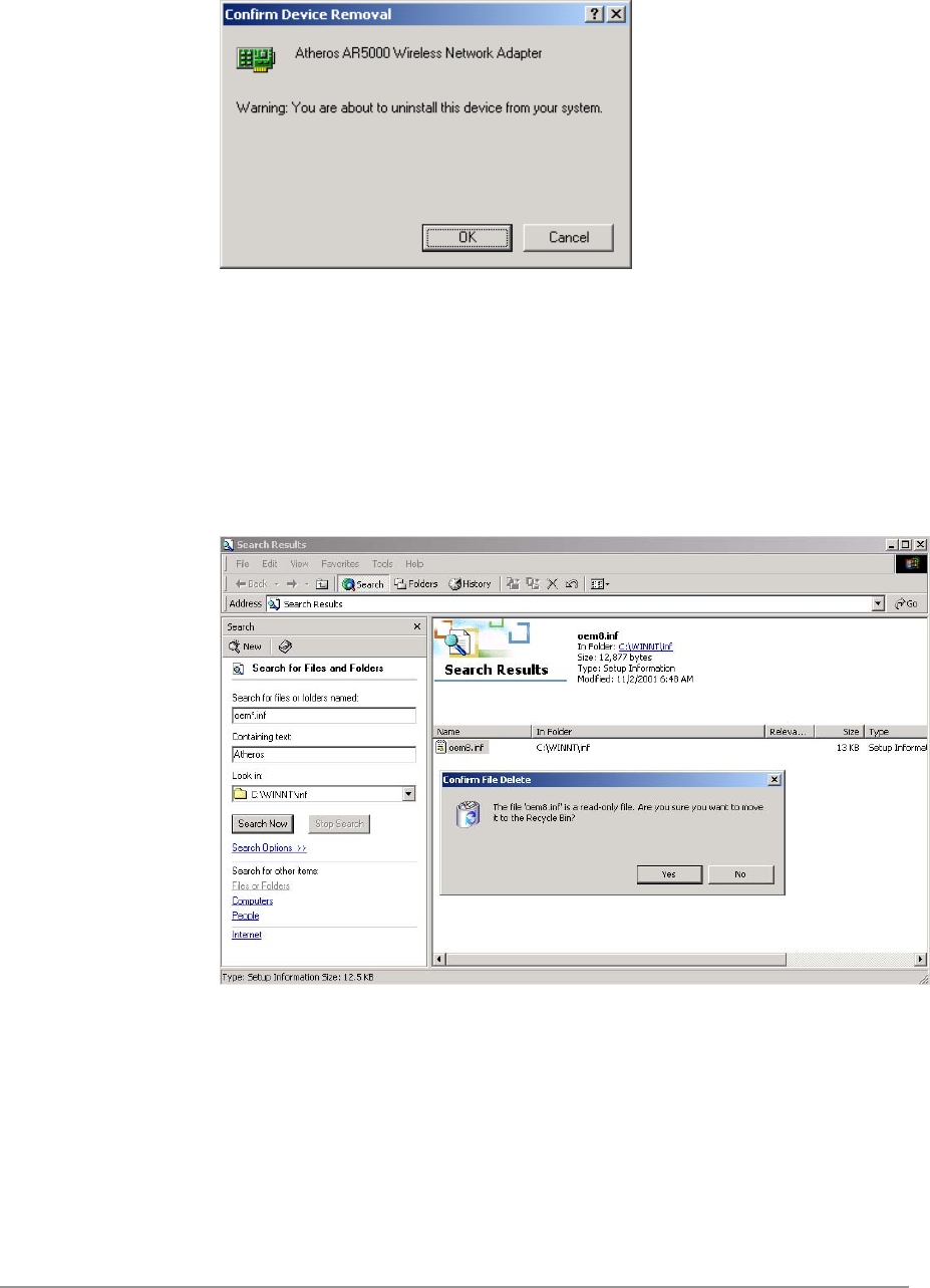
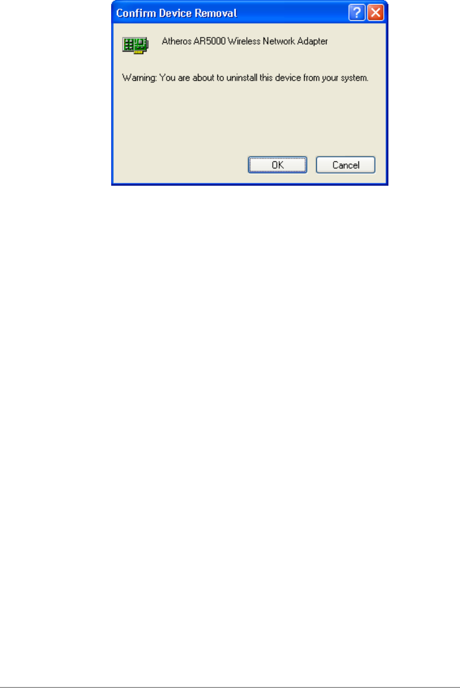
2. Click OK to uninstall the device.
3. When the device is uninstalled from Device Manager, search for and
delete the driver files that reside in the system. To do so, go to the Start
menu and choose Search For Files or Folders…, enter “oem*.inf” in the
“Search for files or folders named:” field, and enter “D-Link” in the
“Containing text:” field. Click Search Now. A few files matching these
criteria are possible, if previous drivers have not been removed properly.
Choose the files that have been found and delete them from the system.
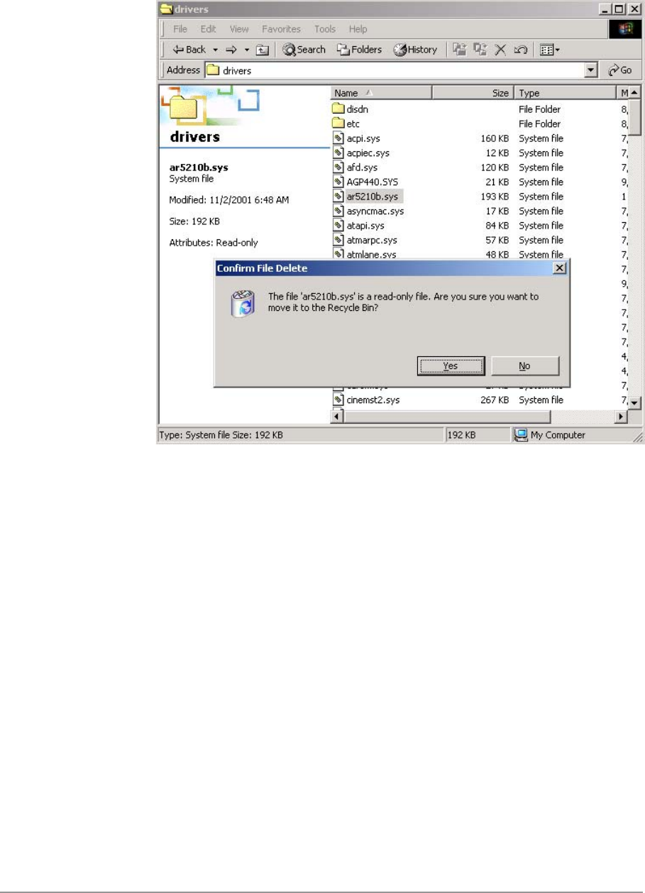
2-16
4. To complete the uninstallation, “ar5210b.sys” should also be removed
from the “\WINNT\system32\drivers” folder.
2-17
Device Configuration
Configuration of the D-Link DWL-A650 Wireless Network Adapter can be
done through the Network Control Panel (NCP) in adapter properties. You
can set the Wireless Network Adapter to work in one of two modes, either
infrastructure mode (which leverages an AP) or ad hoc mode (which consists
of a group of stations participating in the WLAN).
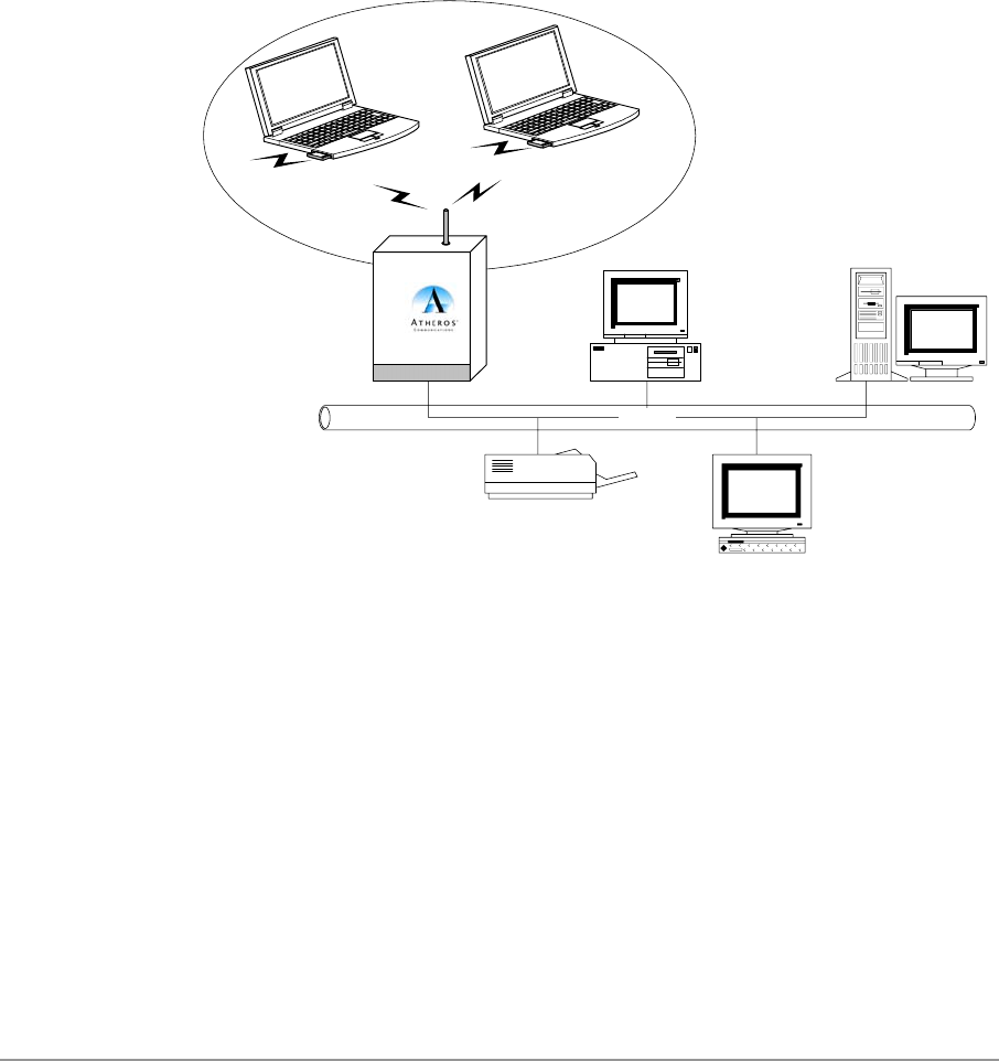
In infrastructure mode, the Wireless Network Adapter participates in a basic
service set (BSS) as a station, and communicates with the other stations
through an AP, as illustrated in Figure 2-1.
Ethernet
STA1 STA2
AP
Figure 2-1. Infrastructure Mode
2-18
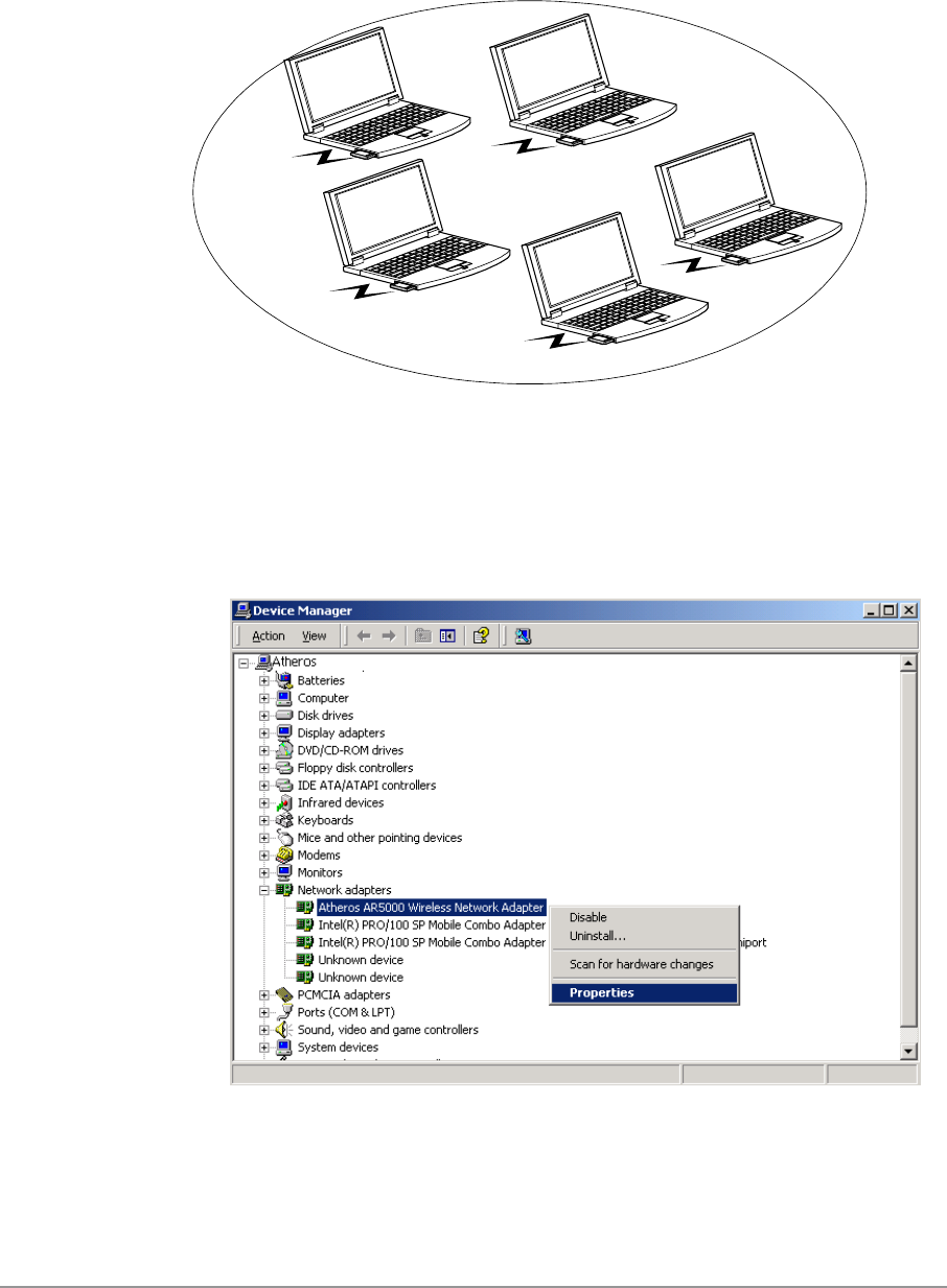
In ad hoc mode, a Wireless Network Adapter works within an independent
basic service set (IBSS), as illustrated in Figure 2-2. All stations
communicate directly with other stations without an AP.
STA1
STA2
STA3
STA4
STA5
Figure 2-2. Ad Hoc Mode
To configure the DWL-A650 Wireless Network Adapter:
1. In the Device Manager, right-click “D-Link DWL-A650 Wireless Network
Adapter,” and click Properties to access the properties of the adapter.
2-19
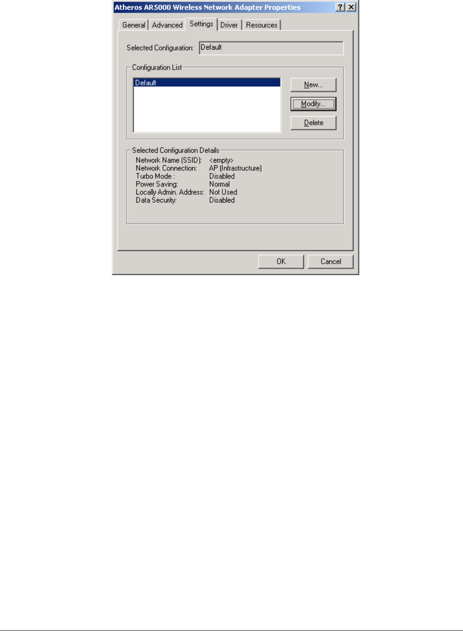
2. Configuration additions, modifications, and deletions are made under the
“Settings” tab of the “D-Link DWL-A650 Wireless Network Adapter”
properties.
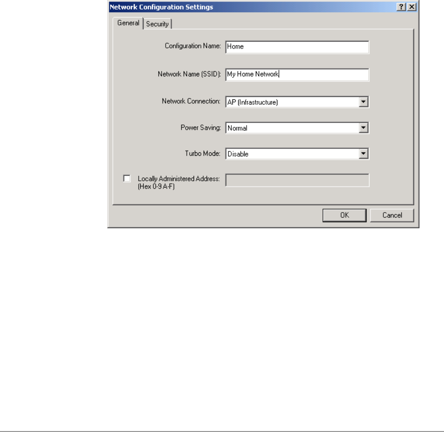
3. Select one of the configurations under the configuration list, and click
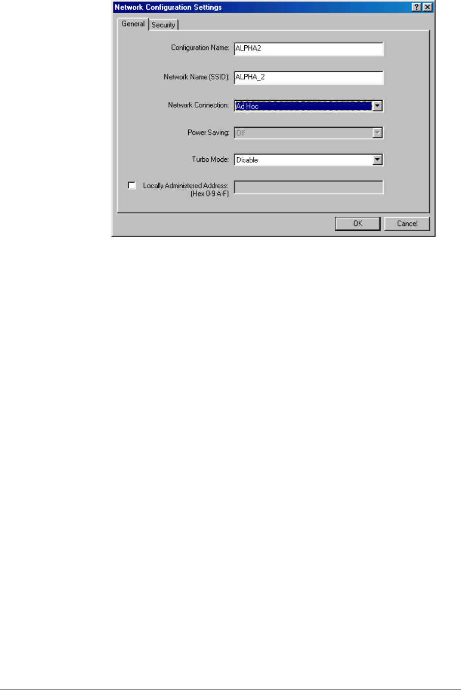
Modify to show the “Network Configuration Settings” screen. This
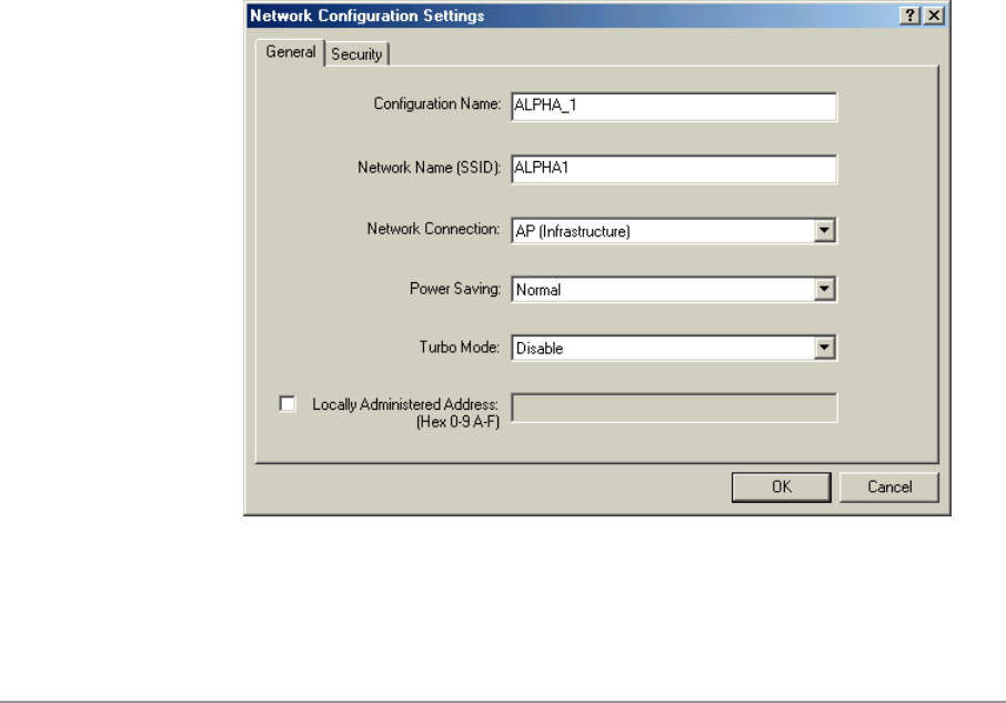
property sheet has two pages: General and Security. The General page
has the following fields:
− Configuration Name: This field identifies the configuration. This name
must be unique. Configuration names are case insensitive.
− Network Name (SSID): This is the name of the IEEE 802.11a
wireless network, for example, “D-Link 802.11a Wireless Network.”
This field has a maximum limit of 32 characters.
− Network Connection: This field defines whether the STA is configured
for an ad hoc or infrastructure network.
2-20
− Power Saving: This field allows the configuration of power
management options. The options are Off, Normal, and Maximum.
Power management is disabled when ad hoc mode is selected in the
Network Connection field. When the Power Saving setting is Off, the
adapter receives full power from the PC. When the Power Saving
setting is Normal, the driver turns off power to the adapter for brief
periods over briefly-spaced time intervals. When the Power Saving
setting is Maximum, the driver turns off power to the adapter for
longer periods over more widely-spaced time intervals.
− Turbo Mode: This field enables or disables D-Link turbo mode.
− Locally Administered Address: This field defines the locally
administered MAC address (LAA). To enter a value in the address
field, the check box needs to be selected. Typically, an LAA is not
required, because the driver automatically loads a unique, globally
administered address from the EEPROM.
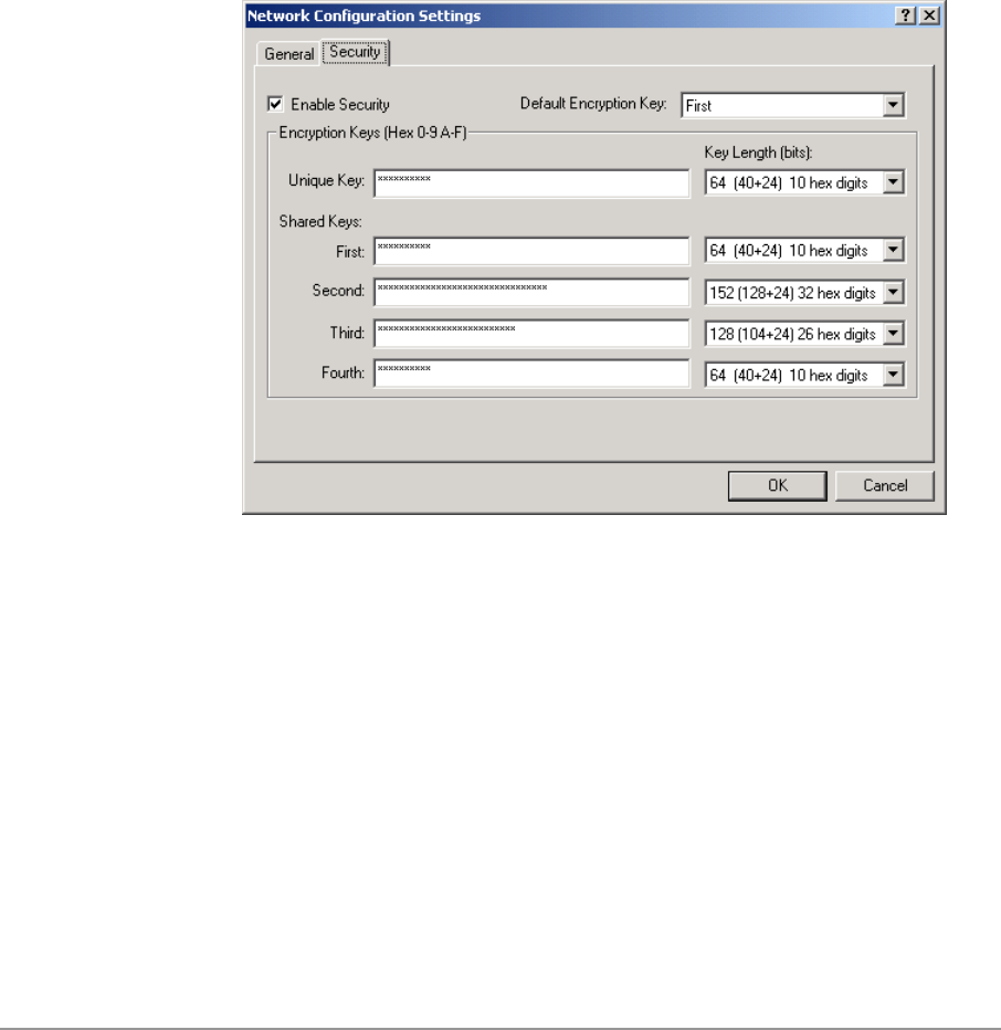
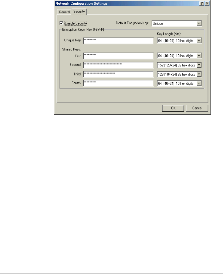
4. The next tab on this property sheet allows for the selection of security
features. The fields on this page are as follows:
− Enable Security: This field completely enables or disables the IEEE
802.11 wired equivalent privacy (WEP) security feature.
− Default Encryption Key: This field defines the type of encryption key
to use (either Unique Key or Shared Keys). This field allows you to
select only a key (Unique, First, Second, Third, or Fourth) whose
corresponding field has been completed.
2-21
− Unique Key: This field defines the unique encryption key for security
for the current network configuration. In ad hoc mode, this encryption
key type is not used. To enable security using a Unique Key, this field
must be populated.
− Shared Keys: These fields define a set of shared encryption keys.
To enable security using Shared Keys, at least one Shared Key field
must be populated.
− Key Length: This field defines the length for each encryption key.
As the Key Length is changed, the number of available characters in
the field is changed automatically. If after a key is entered the length
is adjusted to a smaller number, the key is automatically truncated to
fit. If the length is increased again, the field is not automatically
updated to its previous value.
All encryption key fields are displayed only when initially entered. On
subsequent entry into the security property page, the fields are masked.
The keys must be entered as hexadecimal digits.
2-22
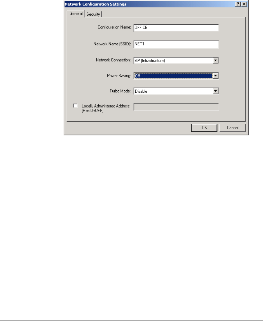
Infrastructure Mode
To configure an D-Link DWL-A650 Wireless Network Adapter in
infrastructure mode:
1. Ensure that the “Locally Administered Address” checkbox is unchecked.
2. Choose the following settings:
− Configuration Name: This field identifies the configuration. This name
must be unique. Configuration names are case insensitive.
− Network Name (SSID): This is the name of the IEEE 802.11a
wireless network, for example, “D-Link 802.11a Wireless Network.”
This field has a maximum limit of 32 characters. If this field is left
blank, the STA connects to the AP with the best signal strength.
− Network Connection: AP (infrastructure).
− Power Saving: This field allows the configuration of power
management options. The options are Off, Normal, and Maximum.
− Turbo Mode: This field enables or disables D-Link turbo mode.
− Locally Administered Address: This field defines the locally
administered MAC address (LAA). To enter a value in the address
field, the check box needs to be selected.

2-23
Usually infrastructure mode is used in an enterprise environment where APs
are installed and maintained by corporate IT staff. Much of the data in the
enterprise network is confidential. It is important to configure security to make
sure only stations with appropriate keys can receive sensitive data. The D-
Link DWL-A650 Wireless Network Adapter and NDIS driver support key
lengths of 40 bits, 104 bits, and 128 bits. Typically, the appropriate encryption
and decryption keys are supplied by the corporate IT staff.
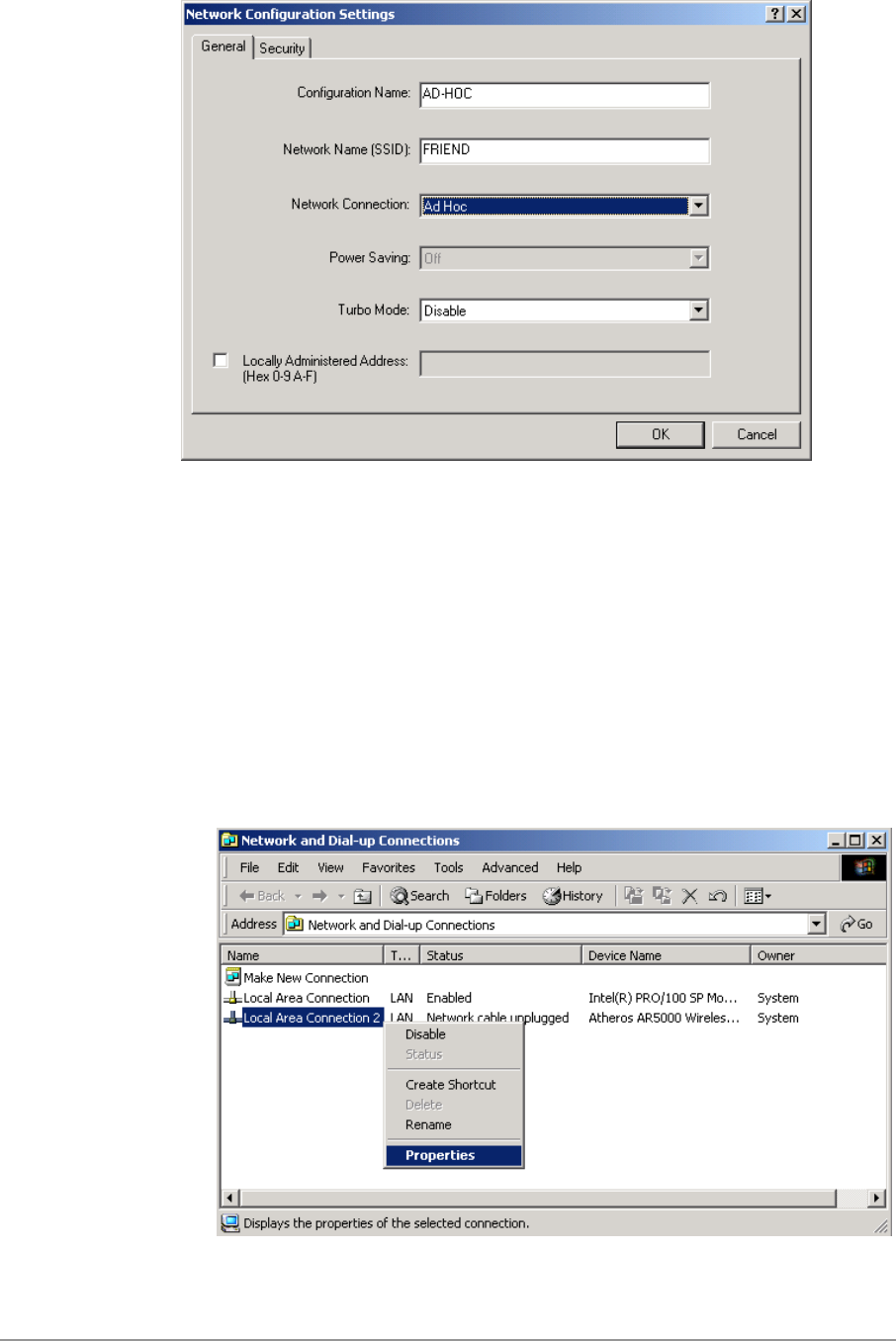
Ad Hoc Mode
An ad hoc network usually is a short-lived network with a small number of
stations. The network is usually created for a special purpose such as
exchanging data between friends, or between customer and client. Because
the duration of the ad hoc network tends to be limited, Power Saving and
Security features are not typically a requirement. For ad hoc network activity,
the Power Saving and Security features can be disabled. Currently, shared
key security is supported in ad hoc mode. Future D-Link software
implementations will provide unique key support.
In ad hoc mode, a station scans the air for an existing BSS. If no BSS is
found, the station establishes a BSS for other stations to join. When other
stations scan the air and find an established BSS in place, they join that BSS
to form an ad hoc network. If a specific set of stations requires ad hoc
network connectivity, it is recommended to have one station establish a BSS
first before configuring the remaining stations. This prevents the scenario of
several stations trying to form a BSS at the same time, which can result in
multiple singular BSSs being established, rather than a single BSS with
multiple stations.
Configuration Name: This field identifies the configuration. This name
must be unique. Configuration names are case insensitive.
Network Name (SSID): A Network Name is mandatory for ad hoc mode.
The SSID for all stations in a single ad hoc network must be the same.
Network Connection: Ad Hoc.
Power Saving: Power saving mode is not currently supported in an ad
hoc network.
Turbo Mode: All stations participating in the ad hoc network must have
the same rate setting.
Locally Administered Address: This field defines the locally administered
MAC address (LAA). To enter a value in the address field, the check box
needs to be selected.
2-24
TCP/IP Setup
After configuring the D-Link DWL-A650 Wireless Network Adapter through
the Network Control Panel, the TCP/IP address for the network device must
be configured.
1. Open the “Control Panel” and click “Network and Dial-up Connections.”
2. Find the “Local Area Connection” that is associated with the D-Link DWL-
A650 Wireless Network Adapter. Right-click that connection, and click
Properties.
2-25
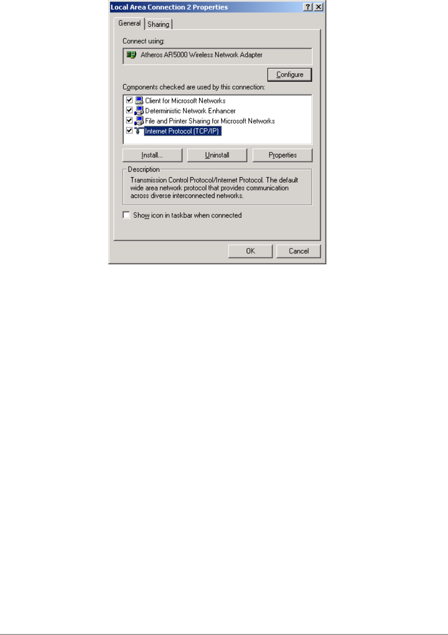
3. Select “Internet Protocol (TCP/IP)” and click Properties.
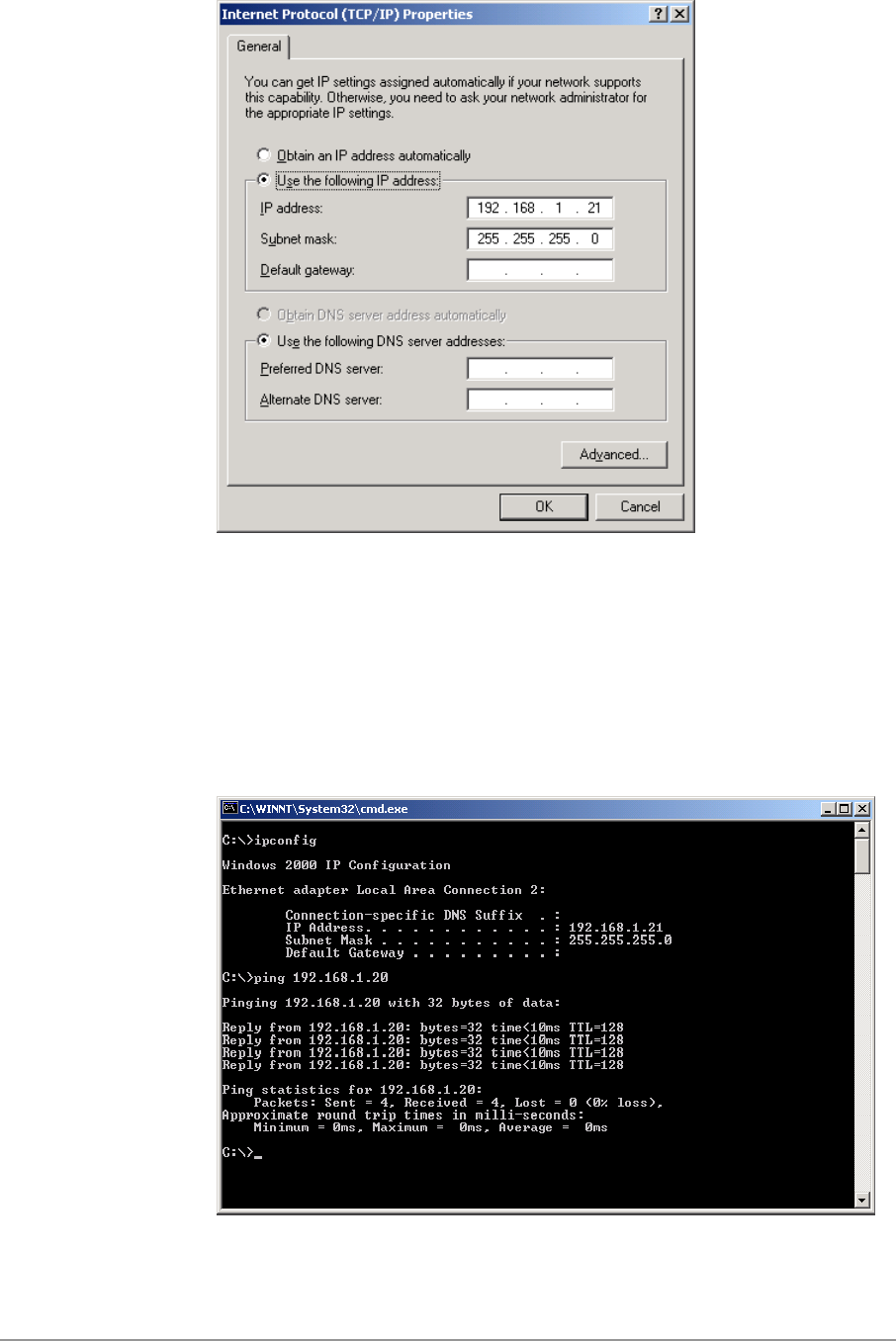
4. Click “Use the following IP address” and input an IP address and Subnet
mask. Assigning an IP address and Subnet mask allows stations to
operate in infrastructure mode and to have Internet access. “Default
gateway” and “DNS server” information is also required. IP configuration
information (DHCP or assigned IP address, Gateway and DNS server IP
addresses) is usually obtained from the corporate IT staff.
5. After obtaining IP configuration information from the appropriate IT staff,
click OK in both “Internet Protocol (TCP/IP) Properties” and “Local Area
Connection Properties” to complete the IP configuration.
2-26
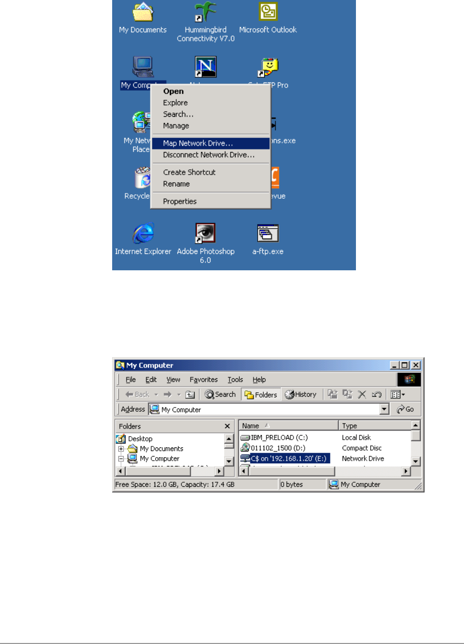
6. Choose Start > Programs > Accessories > Command Prompt to open the
DOS command prompt window. Type “ipconfig” at the C:\> prompt to
determine if the TCP/IP configuration has taken effect. To test IP
connectivity in ad hoc or infrastructure mode, use the “ping <ipaddress>”
command. When a TCP/IP connection is established, the LinkMon utility
(See Chapter 7) can be used to monitor the D-Link DWL-A650 Wireless
Network Adapter operating status.
2-27
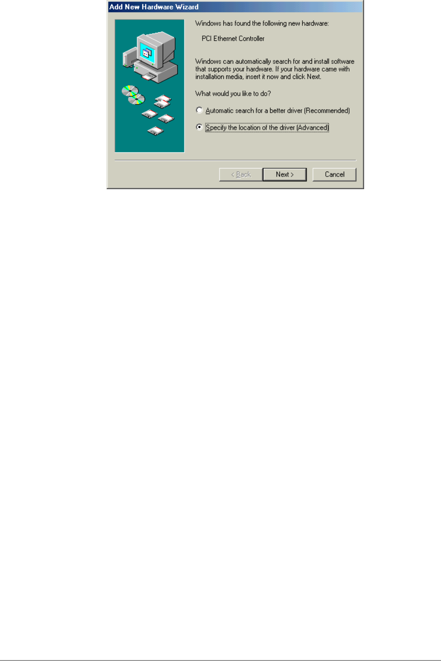
7. To map the drive on another machine to your computer, right-click “My
Computer” and click “Map Network Drive….”
8. After mapping the drive, you can perform file transfers, use video
streaming applications, and all other network data transfers that are
normally performed with wired 10/100 Ethernet connections.

3-1
3
Windows Millennium
Edition
Driver Installation
D-Link recommends that you remove any existing D-Link NDIS driver on the
PC system before installing Version Error! Reference source not found.
release of the NDIS driver. See Section “Driver Uninstallation” on page 3-5
for the instructions on how to remove previous driver releases. When the
system no longer has the D-Link NDIS driver installed, insert the DWL-A650
Wireless Network Adapter into a 32-bit CardBus slot, and follow these steps
to install the NDIS driver:
1. Wait for the following dialog box to appear. Choose “Specify the location
of the driver (Advanced),” and click Next to continue.
3-2
3-3
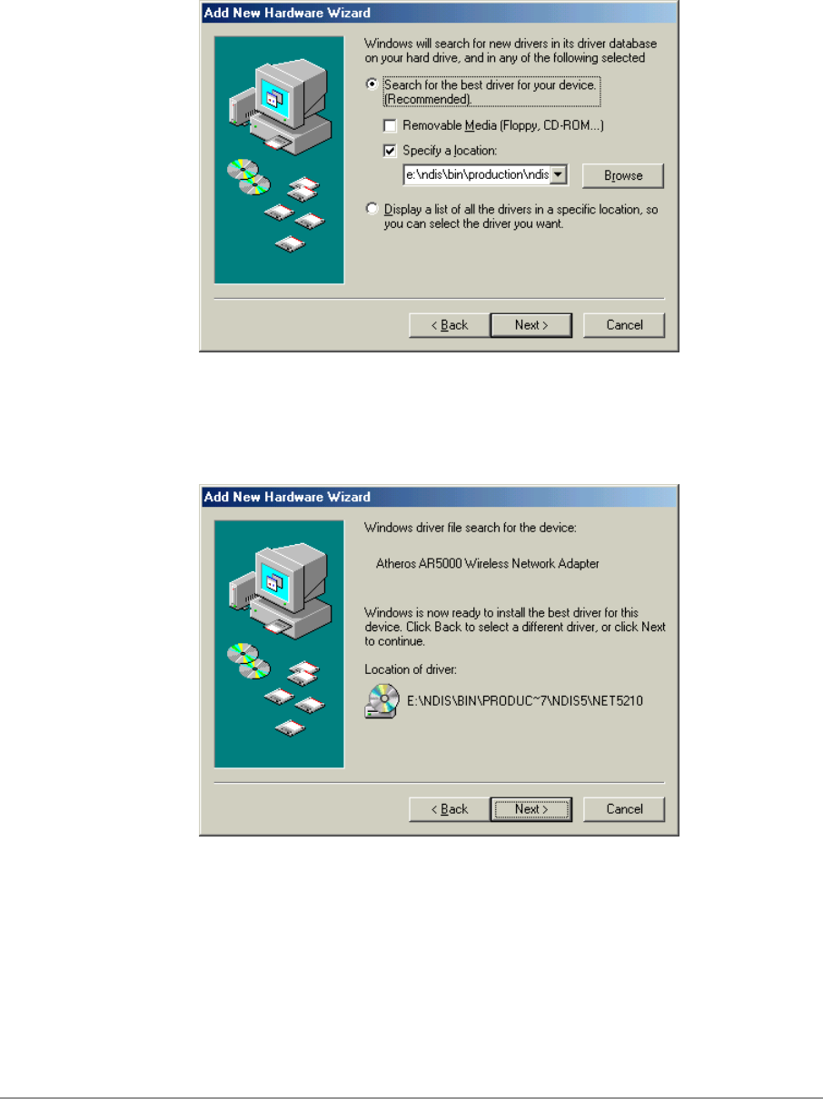
2. Choose “Search for the best driver for your device. (Recommended)” and
select “Specify a location.” Click Browse to locate the NDIS driver. The
default folder is “E:\ndis\bin\production\ndis5” (assuming E: is the CD-
ROM drive). Click Next to continue.
3. When the D-Link driver installation file (NET5210B.INF) has been found,
click Next to continue.
3-4
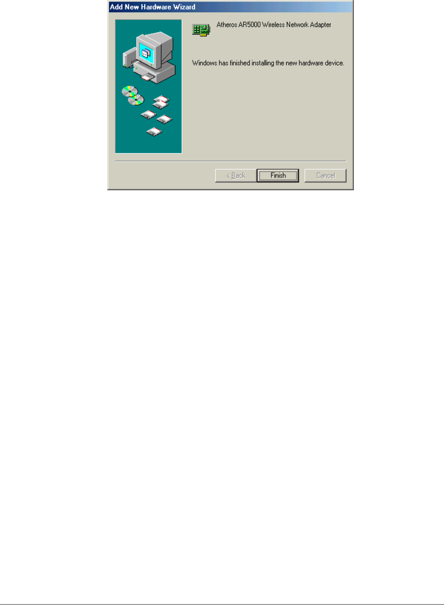
4. Click Finish to continue, and restart the system to complete driver
installation. Refer to Section “Device Configuration” on page 3-7 for
device configuration.
3-5
Driver Uninstallation
This section provides uninstallation procedures for removing the D-Link NDIS
driver from the system. Uninstallation is recommended for upgrading the
NDIS driver from previous D-Link driver releases.
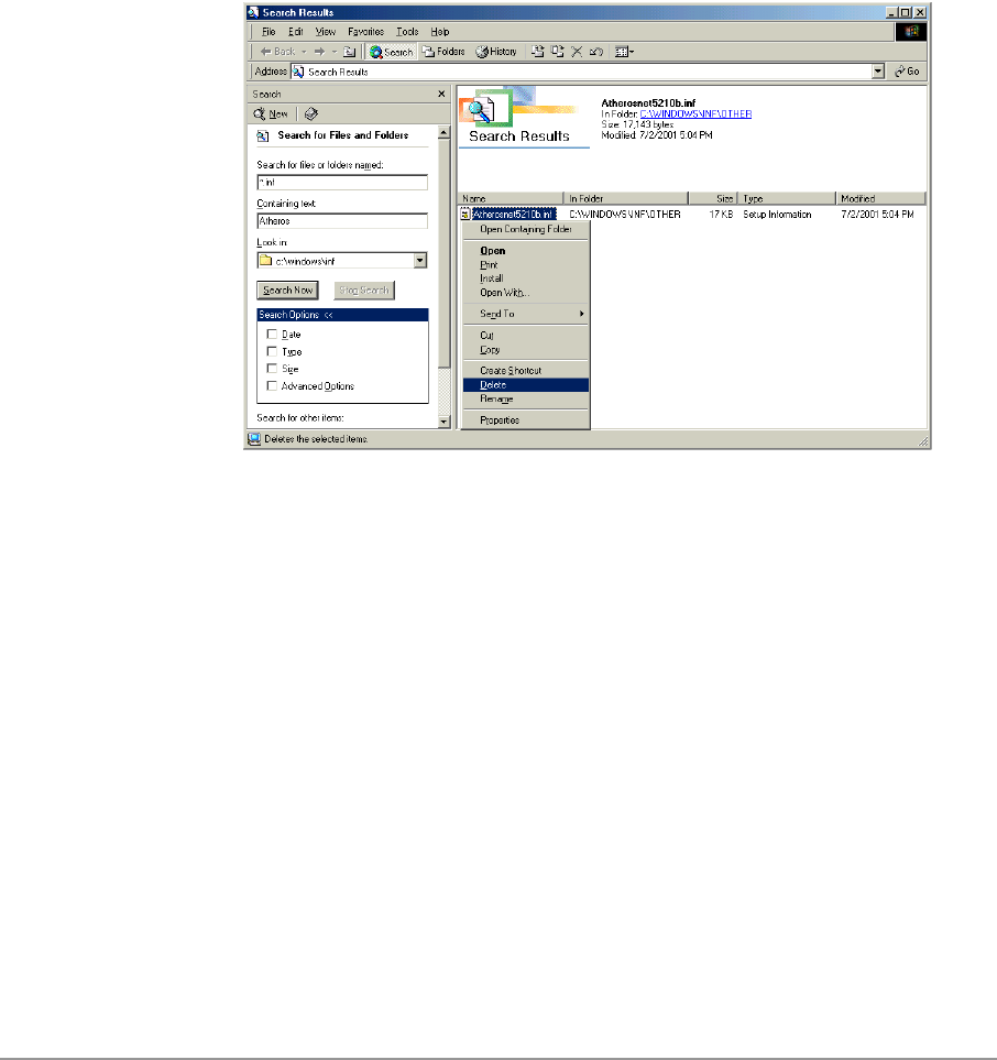
1. To remove the NDIS driver from the OS, go to Start > Search > For Files
or Folders…, and search for the INF file containing the “D-Link” text string
under the \WINDOWS\INF folder. Be sure to include subfolders in the
search criteria. When “D-Linknet5210b.inf” has been found, delete it by
right-clicking the file and choose Delete.
3-6
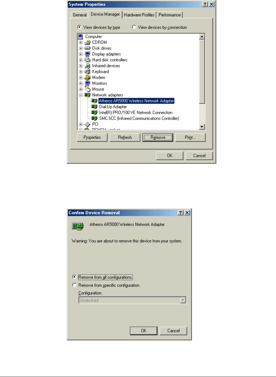
2. From Control Panel, launch the System Properties window. Select “D-
Link DWL-A650 Wireless Network Adapter” from Device Manager, and
click Remove to uninstall the device.
3. Click OK to confirm the removal of the device. Restart the system to
complete un-installation.
3-7
Device Configuration
Configuration of the D-Link DWL-A650 Wireless Network Adapter can be
done through the D-Link NIC Configuration utility found in the Windows
Control Panel. Similar to Windows 2000, the device can be set to work in one
of two modes: infrastructure mode or ad hoc mode. Please refer to Section
“Device Configuration” beginning on page 2-17 for more details on these
network connection types.
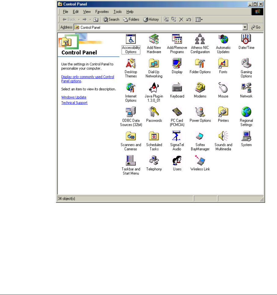
To launch the configuration utility, go to Control Panel and double-click on
the D-Link NIC Configuration icon.
3-8
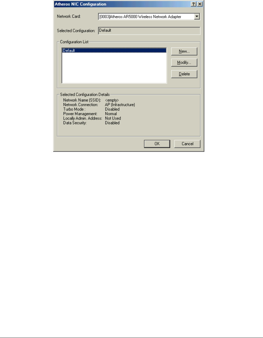
The configuration utility allows addition, modification, and deletion of the
configuration profiles. Select one of the existing configuration profiles under
the configuration list to modify, or click New to add a new configuration
profile. Follow Section “Infrastructure Mode” on page 3-9 and Section “Ad
Hoc Mode” on page 3-10 to set up the station to work in infrastructure mode
and ad hoc mode.
3-9
Infrastructure Mode
This section defines the process of configuring an D-Link DWL-A650
Wireless Network Adapter in infrastructure mode. See Section “Device
Configuration” beginning on page 2-17 for detailed descriptions of each
option in the Network Configuration Settings.
1. Under the “General” tab, make sure the “Locally Administered Address”
checkbox is unchecked. Use the following information as a guideline to
choose the values of each field in the configuration window:
− Configuration Name: This field identifies the configuration. This name
must be unique. Configuration names are case insensitive.
− Network Name (SSID): This is the name of the IEEE 802.11a
wireless network. This field has a maximum limit of 32 characters. If
this field is left blank, the STA connects to the AP with the best signal
strength.
− Network Connection: AP (Infrastructure)
− Power Saving: This field allows the configuration of power
management options. The options are Off, Normal, and Maximum.
− Turbo Mode: This field enables or disables D-Link turbo mode.
3-10
2. Usually, infrastructure mode is used in an enterprise environment where
APs are installed and maintained by corporate IT staff. Much of the data
in the enterprise network is confidential. It is important to configure
security to make sure only stations with appropriate keys can receive
sensitive data. The D-Link DWL-A650 Wireless Network Adapter and
NDIS driver support key lengths of 40 bits, 104 bits and 128 bits.
Typically, the appropriate encryption and decryption keys are supplied by
the corporate IT staff.
Ad Hoc Mode
This section defines the process of configuring an D-Link DWL-A650
Wireless Network Adapter in ad hoc or IBSS mode. See Section “Ad Hoc
Mode” on page 2-23 for descriptions of ad hoc operation.
1. Similar to the set-up of AP Infrastructure mode described in the previous
section, ad hoc mode is also configured by changing the options in the
Network Configuration Settings of the D-Link NIC Configuration utility.
Use the following information as a guideline to choose the values of each
field in the configuration window:
− Configuration Name: This field identifies the configuration. This name
must be unique. Configuration names are case insensitive.
− Network Name (SSID): A Network Name is mandatory for ad hoc
mode. The SSID for all stations in a single ad hoc network must be
the same.
− Network Connection: Ad Hoc.

3-11
− Power Saving: Power saving mode is not currently supported in an ad
hoc network.
− Turbo Mode: All stations participating in the ad hoc network must
have the same rate setting.
− Locally Administered Address: This field defines the locally
administered MAC address (LAA). To enter a value in the address
field, the check box needs to be selected.
2. You can optionally set up other properties, but because the duration of
the ad hoc network tends to be limited, Power Saving and Security
features are not typically a requirement. For ad hoc network activity, the
Power Saving and Security features can be disabled. Currently, shared
key security is supported in ad hoc mode. Future D-Link software
implementations will provide unique key support.
3. Click OK when the properties are set correctly. The system needs to
reboot in order for the changes to take effect.
Note that in ad hoc mode, a station scans the air for an existing BSS. If no
BSS is found, the station establishes a BSS for other stations to join. When
other stations scan the air and find an established BSS in place, they join that
BSS to form an ad hoc network. If a specific set of stations requires ad hoc
network connectivity, it is recommended to have one station establish a BSS
first before configuring the remaining stations. This prevents the scenario of
several stations trying to form a BSS at the same time, which can result in
multiple singular BSSs being established, rather than a single BSS with
multiple stations.
3-12
TCP/IP Configuration
After configuring the D-Link DWL-A650 Wireless Network Adapter network
adapter properties, the TCP/IP address for the network device needs to be
configured.
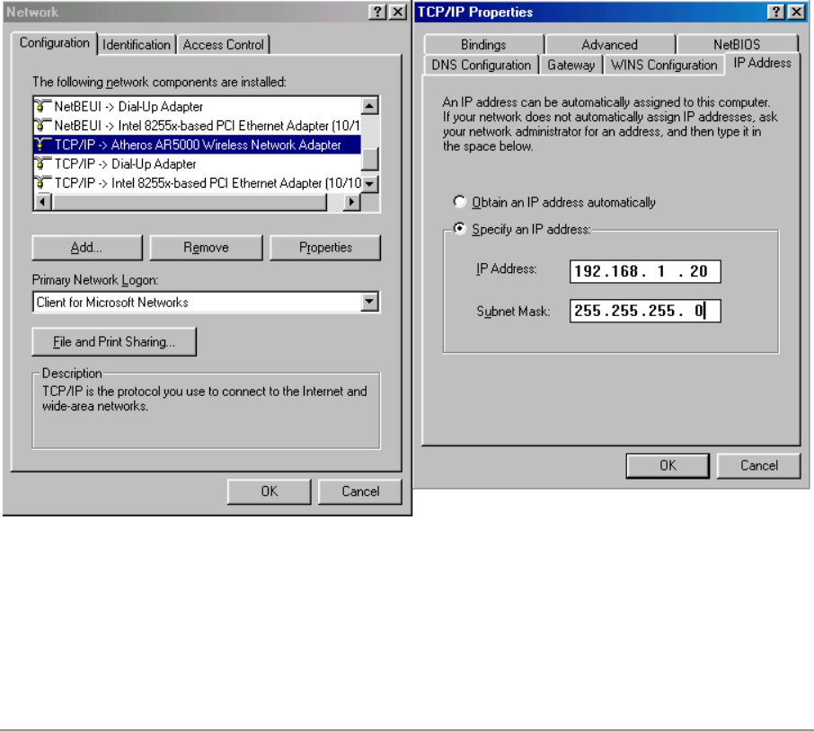
1. From Control Panel, launch the Network properties window. Select
“TCP/IP → D-Link DWL-A650 Wireless Network Adapter” and click
Properties. Depending on the type of network the station connects to,
Gateway and DNS Configuration information can also be required.
IP configuration information (DHCP or assigned IP address, Gateway and
DNS server IP addresses) is usually obtained from the corporate IT staff.
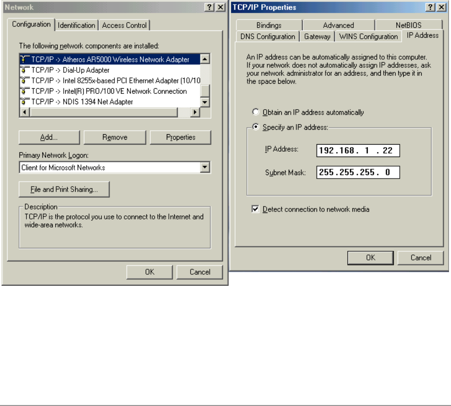
For a simple demonstration, the station is assigned a static IP address.
From “TCP/IP Properties,” choose “IP Address” and select “Specify an IP
address.” Input an IP address and subnet mask. Assigning an IP address
and subnet mask allows the station to interact with the AP or other
stations in the same IP subnet. Click OK to complete the TCP/IP
configuration, and restart the system for the changes to take effect.
3-13
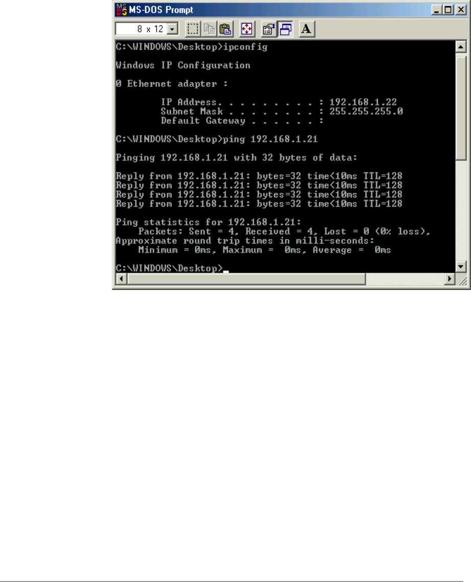
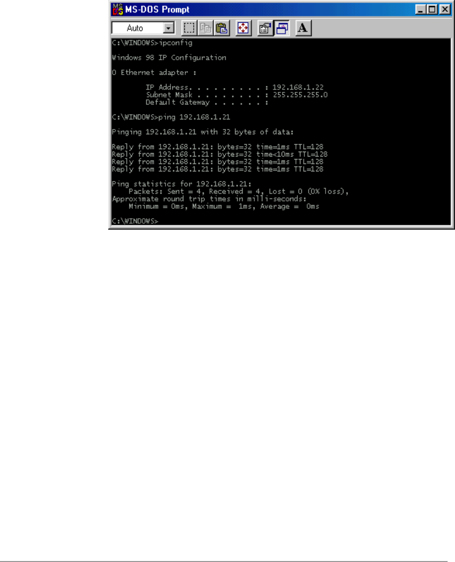
2. Choose Start > Programs > Accessories > Command Prompt to open the
DOS command prompt window. Type “ipconfig” to determine if the
TCP/IP configuration has taken effect. To test IP connectivity in ad hoc or
infrastructure mode, use the “ping <ipaddress>” command. When a
TCP/IP connection is established, the LinkMon utility (see Chapter 7) can
be used to monitor the D-Link DWL-A650 Wireless Network Adapter
operating status.
3-14
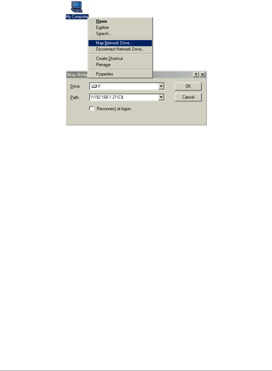
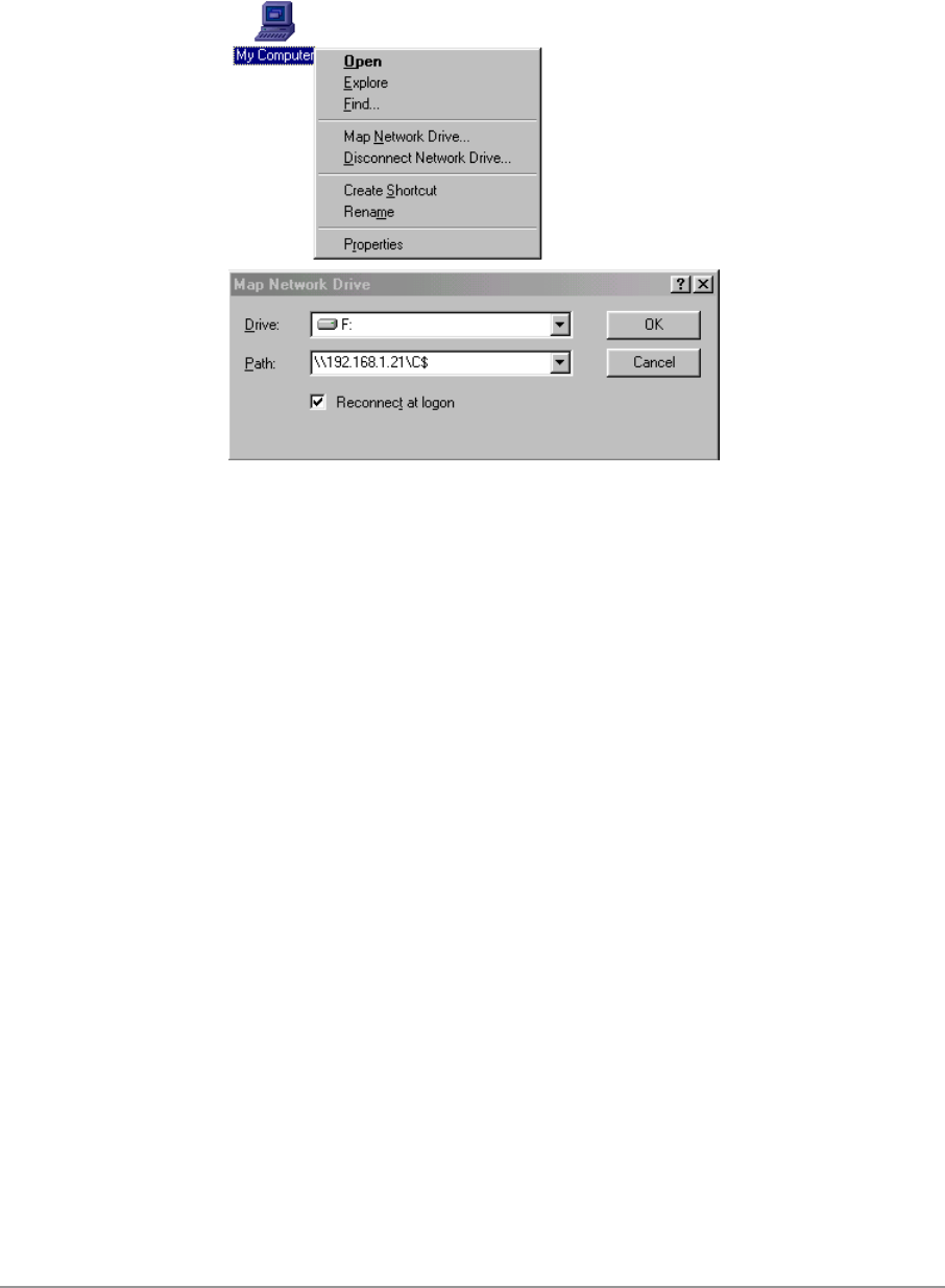
3. To map the drive on another machine to your computer, right-click “My
Computer” and click “Map Network Drive….” Specify the path of a
network-shared folder.
4. After mapping the drive, you can perform file transfers, video streaming,
and all other network data transfers that are normally performed with
wired 10/100 Ethernet connections.

3-15

4-1
4
Windows 98 Second
Edition
Driver Installation
D-Link recommends that you remove any existing D-Link NDIS driver on the
PC system before installing Version 1.3 release of the NDIS driver.
See Section “Driver Uninstallation” on page 4-5 for the instructions on how to
remove previous driver releases. When the system no longer has the D-Link
NDIS driver installed, insert the DWL-A650 Wireless Network Adapter into a
32-bit CardBus slot, and follow these steps to install the NDIS driver:
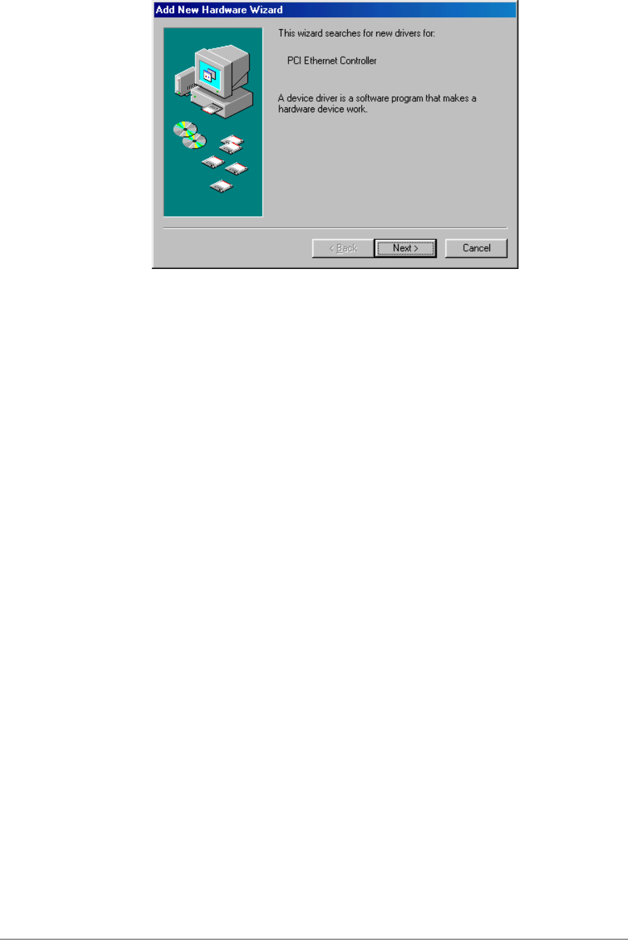
1. Wait for the following dialog box to appear, and click Next to continue.
4-2
4-3
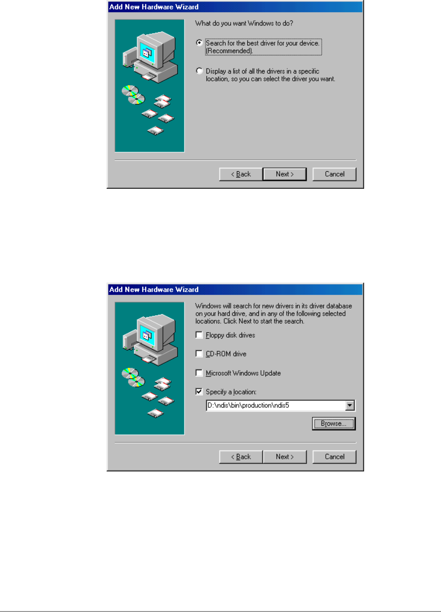
2. Choose “Search for the best driver for your device. (Recommended),”
and click Next.
3. Insert the D-Link Software Release CD in your CD-ROM drive. Choose
“Specify a location” and browse to the location where the NDIS driver is
located. The default folder is D:\ndis\bin\production\ndis5 (assuming D: is
the CD-ROM drive). Click Next to continue.
4-4
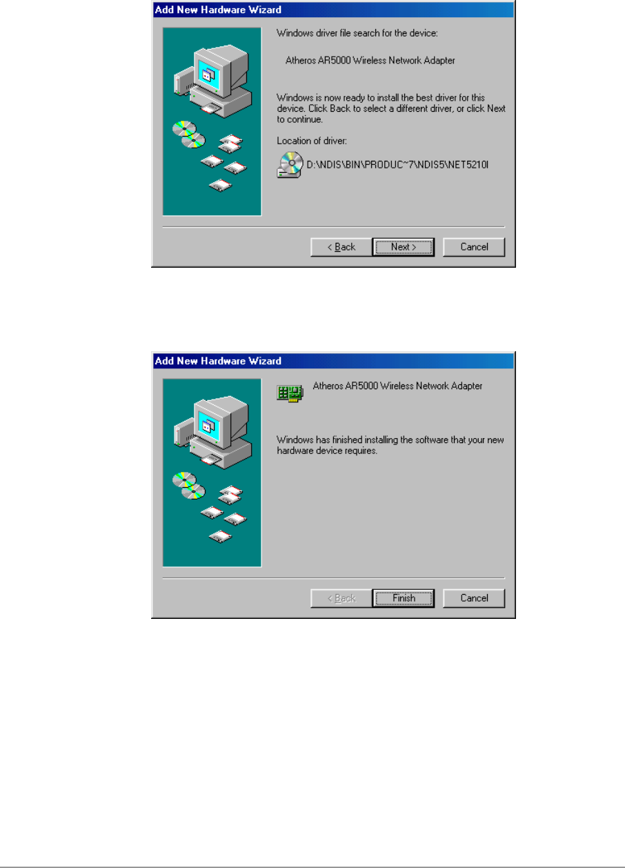
4. When the D-Link driver installation file (NET5210B.INF) has been found,
click Next to continue.
5. Click Finish to continue.
4-5
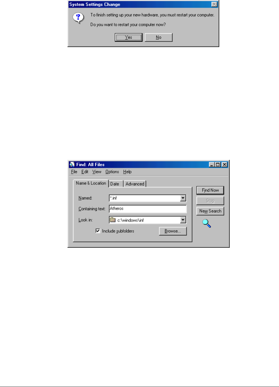
6. Click Yes to restart the system and complete driver installation.
See Section “Device Configuration” on page 4-8 for device configuration.
Driver Uninstallation
This section provides uninstallation procedures for removing the D-Link NDIS
driver from the system. Uninstallation is recommended for upgrading the
NDIS driver from previous D-Link driver releases.
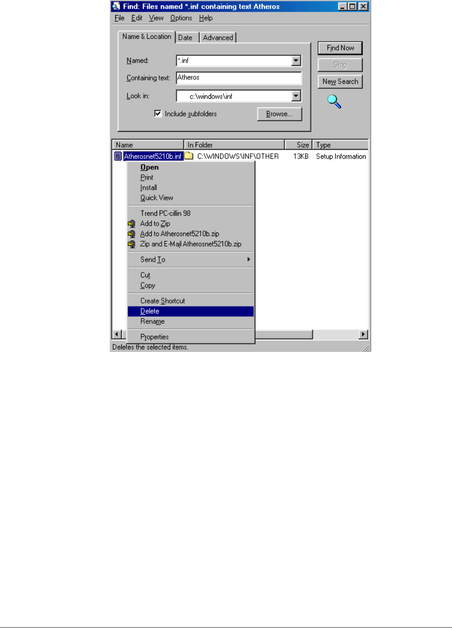
1. To remove the NDIS driver from the OS, go to Start > Search > For Files
or Folders…, and search for the INF file containing the “D-Link” text string
under the \WINDOWS\INF folder. Be sure to include subfolders in the
search criteria.
4-6
2. When “D-Linknet5210b.inf” has been found, delete it by right-clicking the
file and choose “Delete.”
4-7
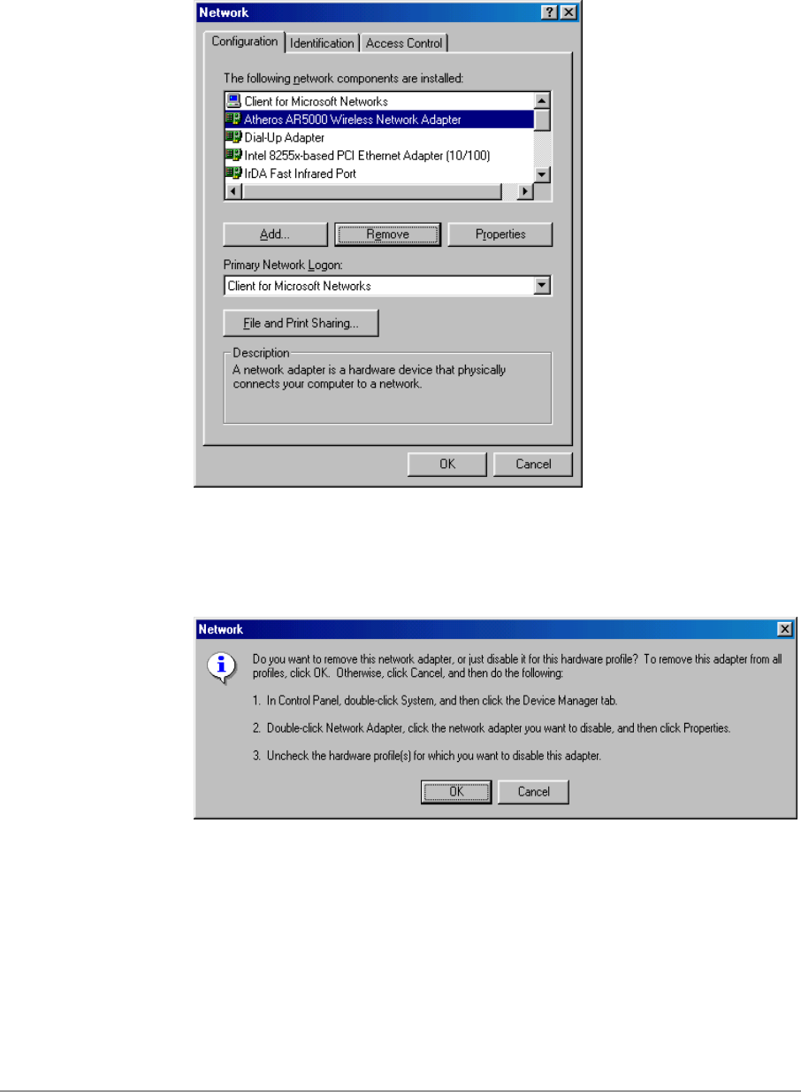
3. From Control Panel, launch the Network properties window. Select “D-
Link DWL-A650 Wireless Network Adapter” from the list, and click
Remove to uninstall the device.
4. Click OK to confirm the removal of the device. Restart the system to
complete uninstallation.
4-8
Device Configuration
Configuration of the D-Link DWL-A650 Wireless Network Adapter can be
done through the D-Link NIC Configuration utility found in the Windows
Control Panel. Similar to Windows 2000 the device can be set to work in one
of two modes: infrastructure mode or ad hoc mode. Please refer to Section
“Device Configuration” beginning on page 2-17 for more details on these
network connection types.
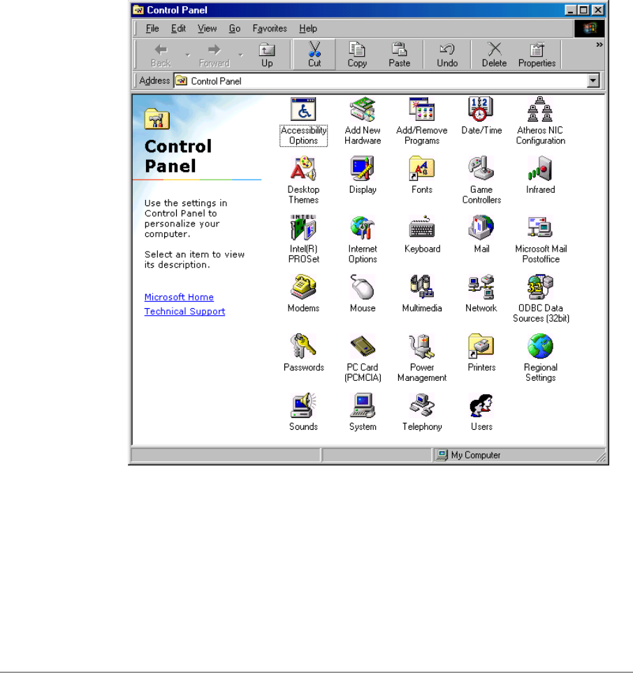
To launch the configuration utility, go to Control Panel and double-click on
the D-Link NIC Configuration icon.
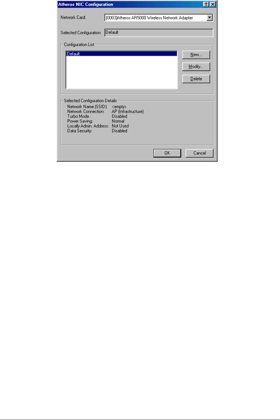
The configuration utility allows addition, modification, and deletion of the
configuration profiles. Select one of the existing configuration profiles under
the configuration list to modify, or click New to add a new configuration
profile. Follow Section “Infrastructure Mode” on page 4-9 and Section “Ad
Hoc Mode” on page 4-11 to set up the station to work in infrastructure mode
and ad hoc mode.
4-9
Infrastructure Mode
This section defines the process of configuring an D-Link DWL-A650
Wireless Network Adapter in infrastructure mode. See Section “Device
Configuration” beginning on page 2-17 for detailed descriptions of each
option in the Network Configuration Settings.
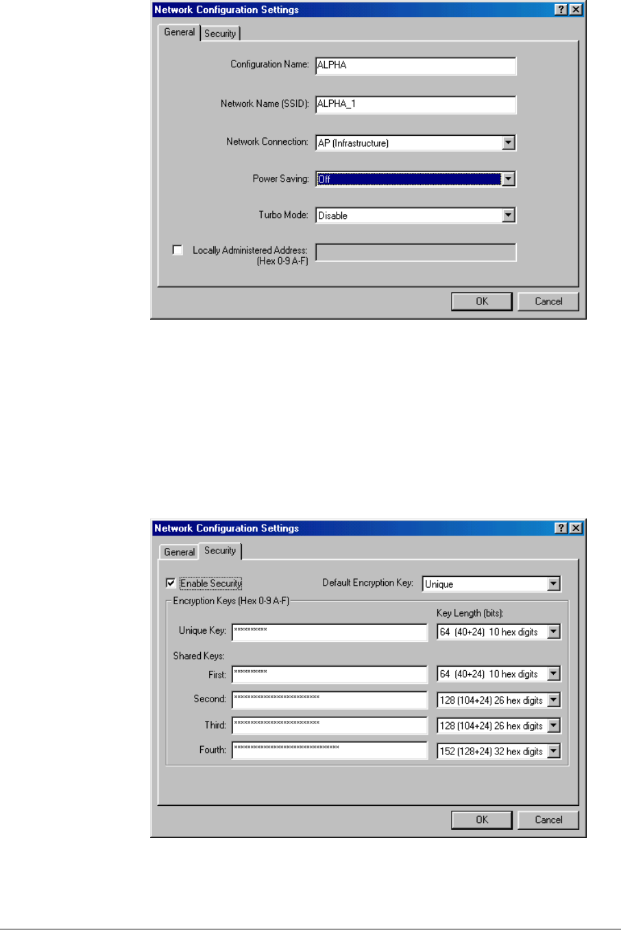
1. Under the “General” tab, make sure the “Locally Administered Address”
checkbox is unchecked. Use the following information as a guideline to
choose the values of each field in the configuration window:
− Configuration Name: This field identifies the configuration. This name
must be unique. Configuration names are case insensitive.
− Network Name (SSID): This is the name of the IEEE 802.11a
wireless network. This field has a maximum limit of 32 characters. If
this field is left blank, the STA connects to the AP with the best signal
strength.
− Network Connection: AP (Infrastructure)
− Power Saving: This field allows the configuration of power
management options. The options are Off, Normal, and Maximum.
− Turbo Mode: This field enables or disables D-Link turbo mode.
4-10
2. Usually, infrastructure mode is used in an enterprise environment where
APs are installed and maintained by corporate IT staff. Much of the data
in the enterprise network is confidential. It is important to configure
security to make sure only stations with appropriate keys can receive
sensitive data. The D-Link DWL-A650 Wireless Network Adapter and
NDIS driver support key lengths of 40 bits, 104 bits, and 128 bits.
Typically, the appropriate encryption and decryption keys are supplied by
the corporate IT staff.

4-11
Ad Hoc Mode
This section defines the process of configuring an D-Link DWL-A650
Wireless Network Adapter in ad hoc or IBSS mode. See Section “Ad Hoc
Mode” on page 2-23 for descriptions of ad hoc operation.
1. Similar to the setup of the AP infrastructure mode described in the
previous section, ad hoc mode is also configured by changing the
Network Configuration Settings of the D-Link NIC Configuration utility.
Use the following information as a guideline to choose the values of each
field in the configuration window:
− Configuration Name: This field identifies the configuration. This name
must be unique. Configuration names are case insensitive.
− Network Name (SSID): A Network Name is mandatory for ad hoc
mode. The SSID for all stations in a single ad hoc network must be
the same.
− Network Connection: Ad Hoc.
− Power Saving: Power saving mode is not currently supported in an ad
hoc network.
− Turbo Mode: All stations participating in the ad hoc network must
have the same rate setting.
− Locally Administered Address: This field defines the locally
administered MAC address (LAA). To enter a value in the address
field, the check box needs to be selected.
4-12
2. You can optionally set up other properties, but because the duration of
the ad hoc network tends to be limited, Power Saving and Security
features are not typically a requirement. For ad hoc network activity, the
Power Saving and Security features can be disabled. Currently, shared
key security is supported in ad hoc mode. Future D-Link software
implementations will provide unique key support.
3. Click OK when the properties are set correctly. The system needs to
reboot in order for the changes to take effect.
Note that in ad hoc mode, a station scans the air for an existing BSS. If no
BSS is found, the station establishes a BSS for other stations to join. When
other stations scan the air and find an established BSS in place, they join that
BSS to form an ad hoc network. If a specific set of stations requires ad hoc
network connectivity, it is recommended to have one station establish a BSS
first before configuring the remaining stations. This prevents the scenario of
several stations trying to form a BSS at the same time, which can result in
multiple singular BSSs being established, rather than a single BSS with
multiple stations.
4-13
TCP/IP Setup
After configuring the D-Link DWL-A650 Wireless Network Adapter network
adapter properties, the TCP/IP address for the network device needs to be
configured.
1. From Control Panel, launch the Network properties window. Select
“TCP/IP → D-Link DWL-A650 Wireless Network Adapter” and click
Properties. Depending on the type of network the station connects to,
Gateway and DNS Configuration information can also be required.
IP configuration information (DHCP or assigned IP address, Gateway and
DNS server IP addresses) is usually obtained from the corporate IT staff.
For a simple demonstration, the station is assigned a static IP address.
From “TCP/IP Properties,” choose “IP Address” and select “Specify an IP
address.” Input an IP address and subnet mask. Assigning an IP address
and subnet mask allows the station to interact with the AP or other
stations in the same IP subnet. Click OK to complete the TCP/IP
configuration, and restart the system for the changes to take effect.
4-14
2. Choose Start > Programs > Accessories > Command Prompt to open the
DOS command prompt window. Type “ipconfig” to determine if the
TCP/IP configuration has taken effect. To test IP connectivity in ad hoc or
infrastructure mode, use the “ping <ipaddress>” command. When a
TCP/IP connection is established, the LinkMon utility (see Chapter 7) can
be used to monitor the D-Link DWL-A650 Wireless Network Adapter
operating status.
4-15
3. To map the drive on another machine to your computer, right-click “My
Computer” and click “Map Network Drive….” Specify the path of a
network-shared folder.
4. After mapping the drive, you can perform file transfers, video streaming,
and all other network data transfers that are normally performed with
wired 10/100 Ethernet connections.

5-1
5
Windows XP
Driver Installation (First-time Install)
D-Link recommends that you remove any existing D-Link drivers on the PC
system before installing Version Error! Reference source not found.
release of the NDIS driver. See Section “Driver Uninstallation” on page 5-6
for the instructions on how to remove previous driver releases. With no
existing D-Link NDIS driver installed, insert the D-Link DWL-A650 Wireless
Network Adapter into a 32-bit CardBus slot, and follow these steps to install
the NDIS driver:
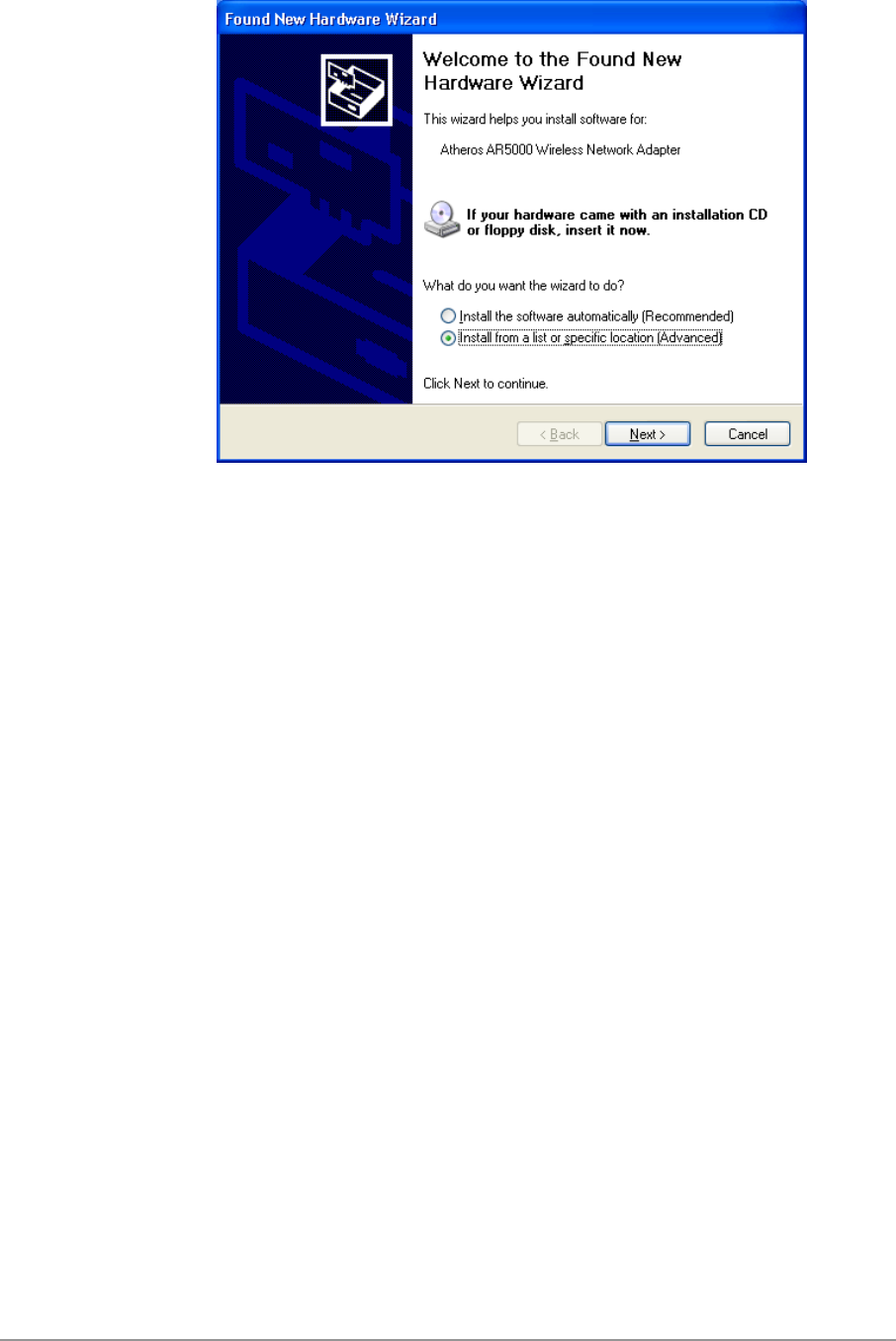
1. Wait for the following dialog box to appear. Choose “Install from a list or
specific location (Advanced),” and click Next to continue.
5-2
5-3
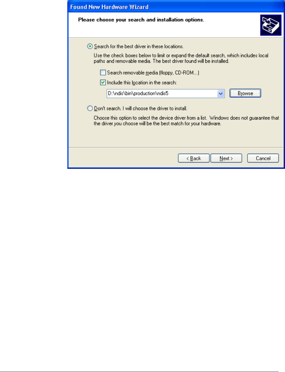
2. Under “Search for the best driver in these locations,” choose “Include this
location in the search” and click Browse to find the location of the NDIS
driver. When the driver location has been identified, click Next to
continue.
5-4
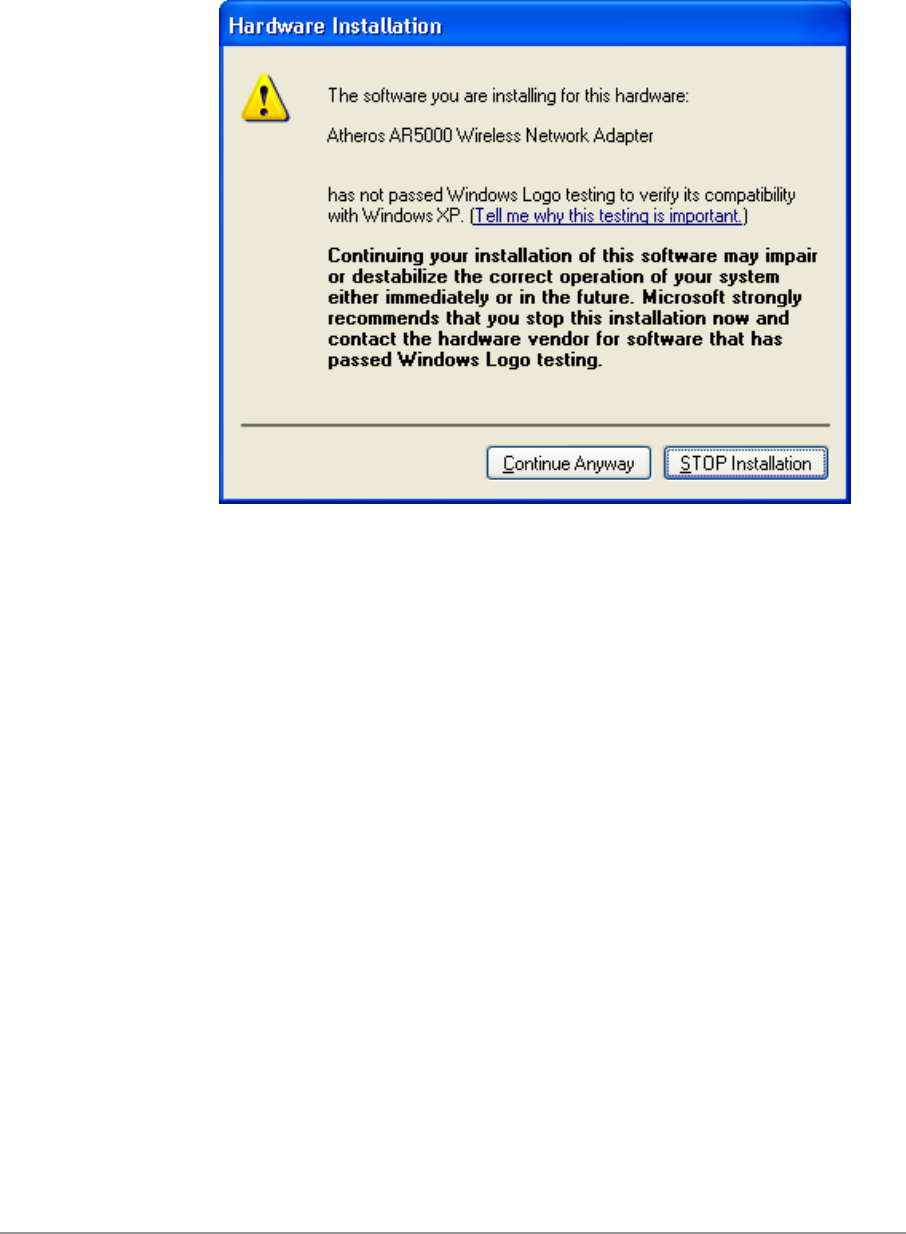
3. The D-Link NDIS evaluation driver currently does not have a digital
signature from Microsoft. Therefore, Windows XP shows a warning
message. Click Continue Anyway to proceed with driver installation.
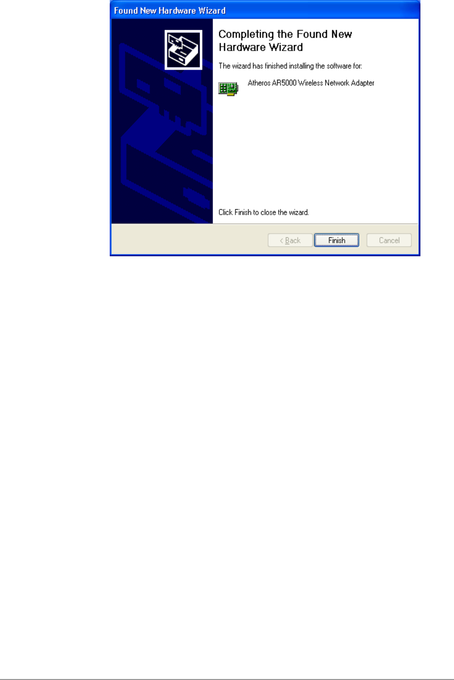
4. Click Finish to complete driver installation, and refer to Section “Device
Configuration” on page 5-10 for device configuration.
5-5
5-6
Driver Uninstallation
This section provides uninstallation procedures for removing the D-Link NDIS
driver from the system. Uninstallation is recommended for upgrading the
NDIS driver from previous D-Link driver releases.
1. To remove the NDIS driver from the OS, go to Device Manager, right
click “D-Link DWL-A650 Wireless Network Adapter,” and choose
Uninstall.
2. Click OK to uninstall the device.
5-7
5-8
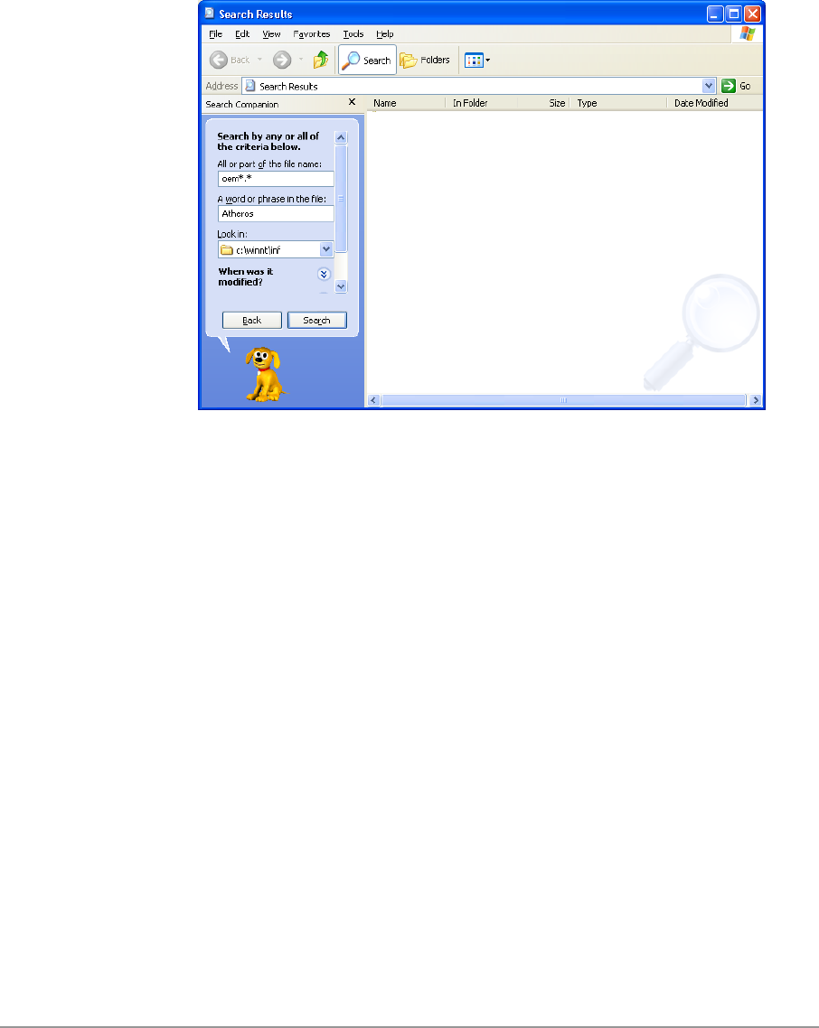
3. When the device is uninstalled from Device Manager, search for and
delete the driver installation file that resides in the system. To do so, go to
Start and choose Search > All files and folder, enter “oem*.inf” in the “All
or part of the file name” field, and enter “D-Link” in the “A word or phrase
in the file” field. Enter “C:\WINNT\INF” in the “Look in” field, where C: is
the drive letter of where Windows XP is installed. Click Search to find the
driver installation file.
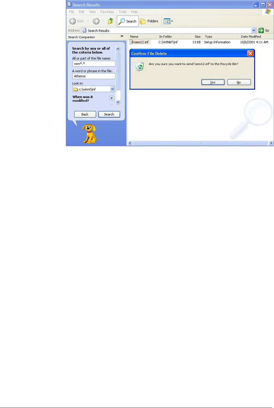
4. A file matching the search criteria is displayed. Choose this file and
delete it from the system.
5-9
5-10
Device Configuration
Windows XP zero-configuration functionality allows the user to select and join
a wireless network without having to configure the device separately. You
can decide to choose the default parameters and directly proceed to zero-
configuration in Section “Windows XP Wireless Network Configuration” on
page 5-20.
Similar to Windows 2000, configuration of the D-Link DWL-A650 Wireless
Network Adapter can be done through the Network Control Panel (NCP) in
adapter properties. You can set the Wireless Network Adapter to work in one
of two modes: infrastructure mode or ad hoc mode. See Section “Device
Configuration” beginning on page 2-17 for more details on these network
connection types.
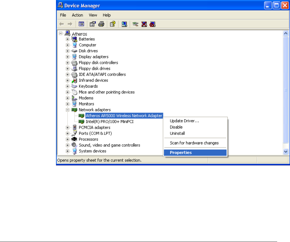
To launch NCP go to Device Manager, right-click “D-Link DWL-A650
Wireless Network Adapter,” and select Properties to access to the properties
of the adapter.
5-11
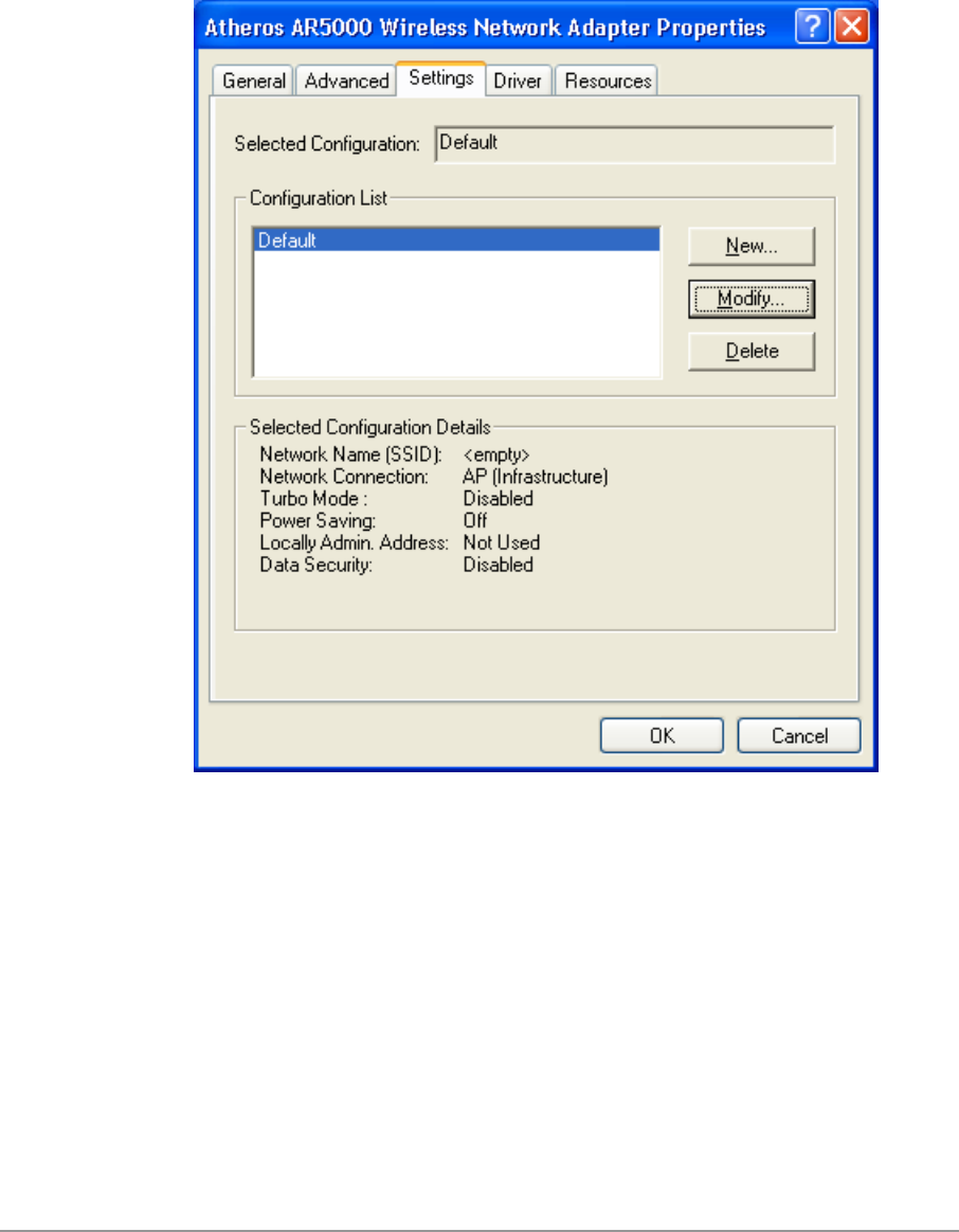
Configuration additions, modifications, and deletions are made under the
“Settings” tab of “D-Link DWL-A650 Wireless Network Adapter Properties.”
Select one of the configurations under the configuration, click Modify or New
and complete the steps in Section “Infrastructure Mode” on page 5-12 or
Section “Ad Hoc Mode” on page 5-13 to set up the station to work in
infrastructure mode or ad hoc mode, respectively.
5-12
Infrastructure Mode
This section defines the process of configuring an D-Link DWL-A650
Wireless Network Adapter in infrastructure mode. See Section “Device
Configuration” beginning on page 2-17 for detailed descriptions of each
option in the Network Configuration Settings.
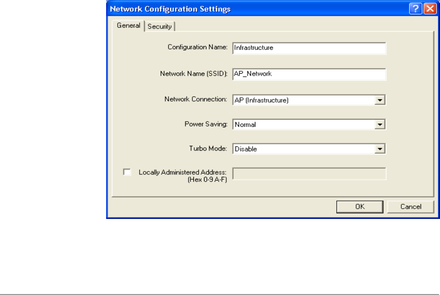
1. Under the “General” tab, make sure the “Locally Administered Address”
checkbox is unchecked. Use the following information as a guideline to
choose the values of each field in the configuration window:
− Configuration Name: This field identifies the configuration. This name
must be unique. Configuration names are case insensitive, for
example, “Infrastructure.”
− Network Name (SSID): This is the name of the IEEE 802.11a
wireless network, for example, “AP_Network.” This field has a
maximum limit of 32 characters. If this field is left blank, the STA
connects to the AP with the best signal strength.
− Network Connection: AP (Infrastructure).
− Power Saving: This field allows the configuration of power
management options. The options are Off, Normal, and Maximum.
− Turbo Mode: This field enables or disables D-Link turbo mode.
5-13
2. Usually, infrastructure mode is used in an enterprise environment where
APs are installed and maintained by corporate IT staff. Much of the data
in the enterprise network is confidential. It is important to configure
security to make sure only stations with appropriate keys can receive
sensitive data. The D-Link DWL-A650 Wireless Network Adapter and
NDIS driver support key lengths of 40 bits, 104 bits and 128 bits.
Typically, the appropriate encryption and decryption keys are supplied by
the corporate IT staff.
Ad Hoc Mode
This section defines the process of configuring an D-Link DWL-A650
Wireless Network Adapter in ad hoc or IBSS mode. See Section “Ad Hoc
Mode” on page 2-23 for descriptions of ad hoc operation.
1. Similar to the setup of AP Infrastructure mode described in the previous
section, ad hoc mode is also configured by changing the options in the
“Network Configuration Settings” window. Use the following information
as a guideline to choose the values of each field in the configuration
window:
− Configuration Name: This field identifies the configuration. This name
must be unique. Configuration names are case insensitive, for
example, “Ad Hoc.”
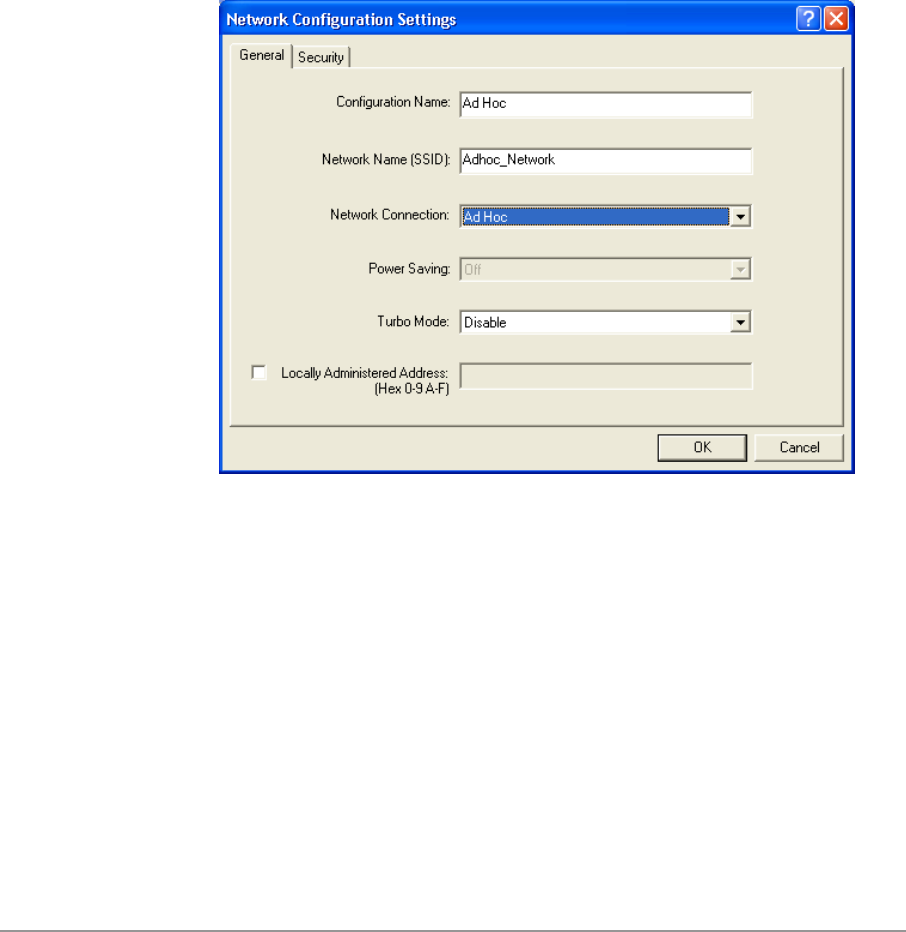
5-14
− Network Name (SSID): A Network Name is mandatory for ad hoc
mode. The SSID for all stations in a single ad hoc network must be
the same.
− Network Connection: Ad Hoc.
− Power Saving: Power saving mode is not currently supported in an ad
hoc network.
− Turbo Mode: All stations participating in the ad hoc network must
have the same rate setting.
− Locally Administered Address: This field defines the locally
administered MAC address (LAA). To enter a value in the address
field, the check box needs to be selected.
2. You can optionally set up security features, but it is not typically a
requirement because the duration of the ad hoc network tends to be
limited. Currently, shared key security is supported in ad hoc mode.
Future D-Link software implementations will provide unique key support.
5-15
3. In ad hoc mode, a station scans the air for an existing BSS. If no BSS is
found, the station establishes a BSS for other stations to join. When other
stations scan the air and find an established BSS in place, they join that
BSS to form an ad hoc network. If a specific set of stations requires ad
hoc network connectivity, it is recommended to have one station establish
a BSS first before configuring the remaining stations. This prevents the
scenario of several stations trying to form a BSS at the same time, which
can result in multiple singular BSSs being established, rather than a
single BSS with multiple stations.
TCP/IP Setup
After configuring the D-Link DWL-A650 Wireless Network Adapter through
the Network Control Panel, the TCP/IP address for the network device needs
to be configured.
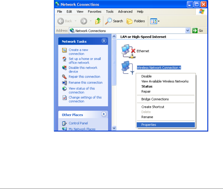
1. From the Start menu, choose Programs > Accessories >
Communications > Network Connections. Find the “Local Area
Connection” that is associated with the D-Link DWL-A650 Wireless
Network Adapter. Right-click that connection and click Properties.
5-16
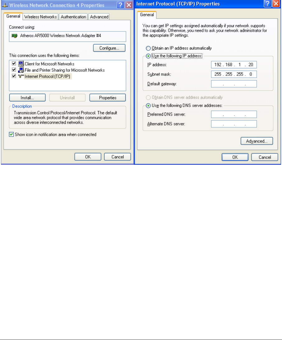
2. Select “Internet Protocol (TCP/IP)” and click Properties. Click “Use the
following IP address” and input an IP address and Subnet mask.
Depending on the type of network the station connects to, Gateway and
DNS Configuration information can also be required. IP configuration
information (DHCP or assigned IP address, Gateway and DNS server IP
addresses) is usually obtained from the corporate IT staff. For a simple
demonstration, the station is assigned a static IP address. Click OK in
both “Internet Protocol (TCP/IP) Properties” and “Local Area Connection
Properties” to complete the IP configuration.
5-17
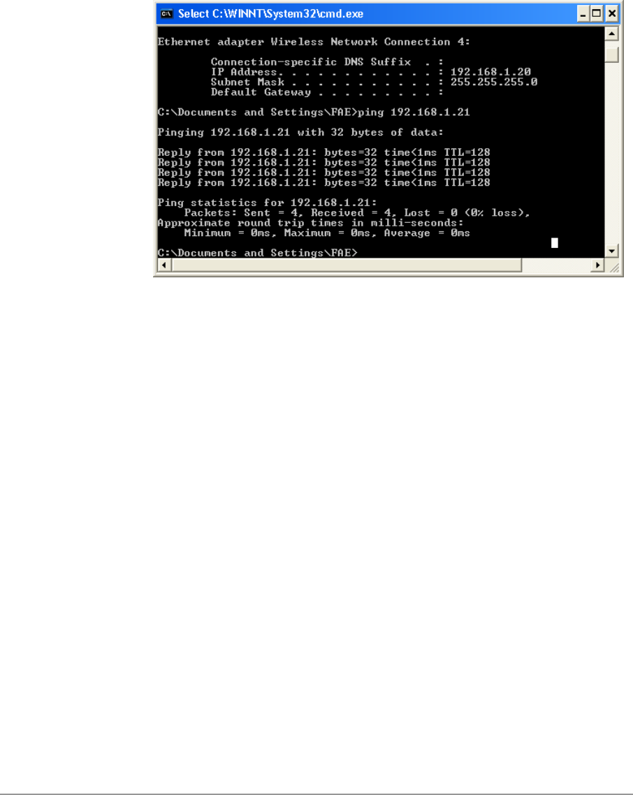
3. Choose Start > Programs > Accessories > Command Prompt to open a
command prompt window. Type “ipconfig” to determine if the TCP/IP
configuration has taken effect. To test IP connectivity in ad hoc or
infrastructure mode, use the “ping <IP address>” command. When a
TCP/IP connection is established, the LinkMon utility (see Chapter 7) can
be used to monitor the operating status of D-Link DWL-A650 Wireless
Network Adapter.
5-18
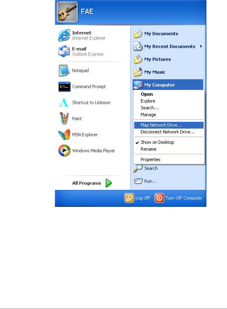
4. To map the drive on another machine to your computer, from the Start
menu, choose My Computer and right-click to select “Map Network
Drive….”
5-19
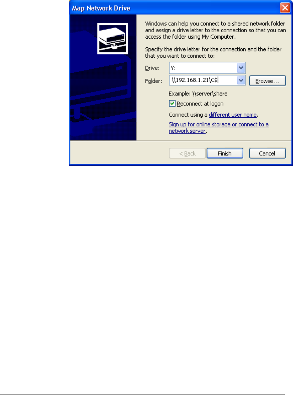
5. Assign the drive letter that maps to the network-shared folder and specify
the shared folder information. Click Finish to map the drive.
6. After mapping the drive, you can perform file transfers, video streaming,
and all other network data transfers that are normally performed with
wired 10/100 Ethernet connections.

5-20
Windows XP Wireless Network Configuration
Aside from using the Network Control Panel (NCP) to configure the D-Link
DWL-A650 Wireless Network Adapter, Windows XP provides zero-
configuration functionality that automatically tries to connect the STA to
available wireless networks in the following order:
a. Infrastructure mode with valid WEP keys
b. Infrastructure mode with unauthenticated access for stations without
WEP keys
c. Ad hoc mode
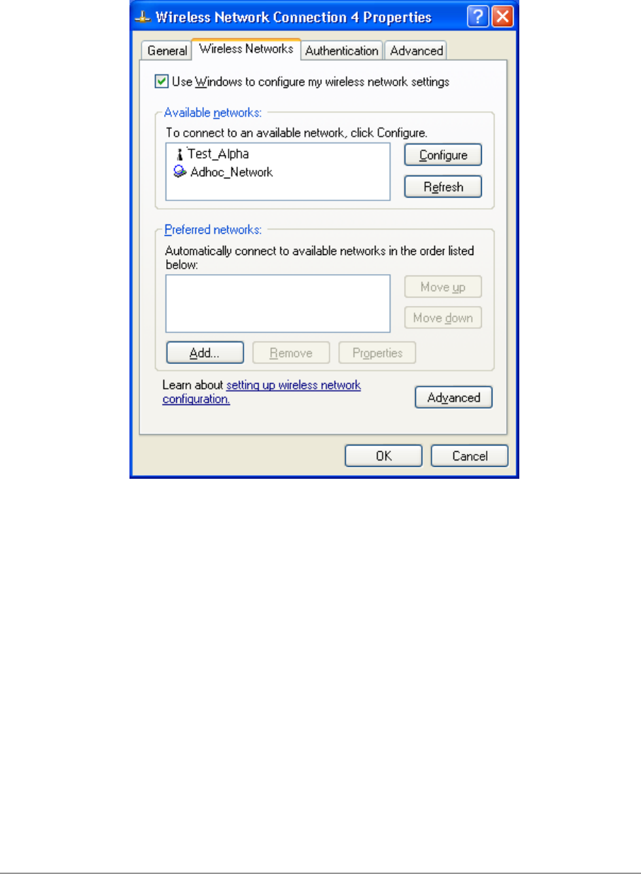
To configure wireless network settings through the Windows XP user
interface, open Network Connections from Control Panel. Right-click the
Local Area Network Connection icon (pertinent to D-Link DWL-A650 Wireless
Network Adapter), click Enable to enable the device first, and then click
Properties. On the Wireless Networks tab, select the “Use Windows to
configure my wireless network settings” check box to enable automatic
wireless network configuration. Follow Section “Infrastructure Mode” on page
5-12 or Section “Ad Hoc Mode” on page 5-13 to set up the station to connect
to an infrastructure or ad hoc network.
If you want to use non-default settings for power saving and turbo mode, you
should set those parameters through the NCP method described in Section
“Device Configuration” on page 5-10. Then use Wireless Networks tabs to
select network name, network type, and encryption keys.
5-21
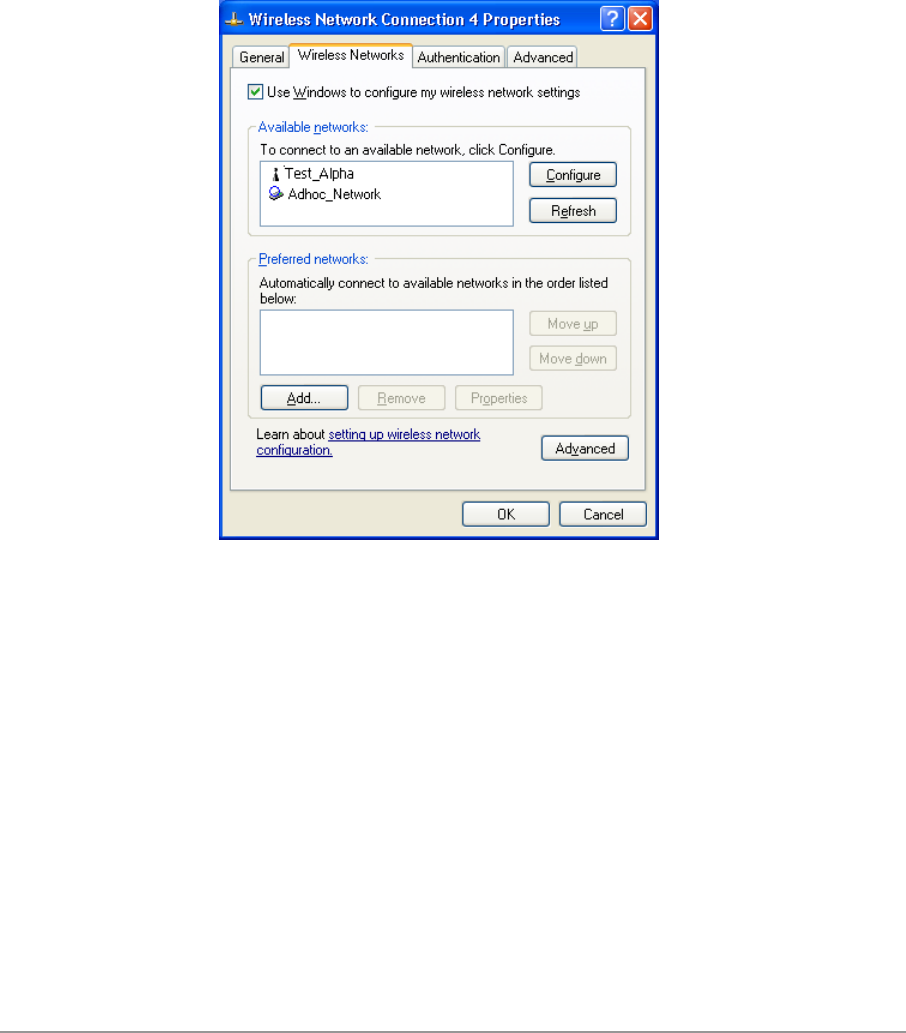
Note that you can disable automatic wireless network configuration, and
revert back to using D-Link NCP configuration settings, by clearing the “Use
Windows to configure my wireless network settings” check box.
5-22
Infrastructure Mode
To set up automatic wireless network configuration to connect to an existing
Access Point (infrastructure network):
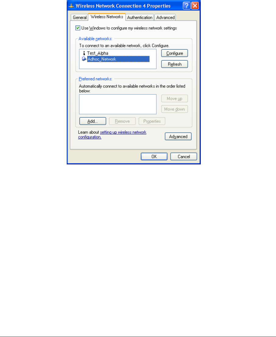
1. Click the network name under “Available networks” in the Wireless
Networks tab, and click Configure. You can update the list of available
networks that are within range of your computer by clicking Refresh
under Available Networks.
5-23
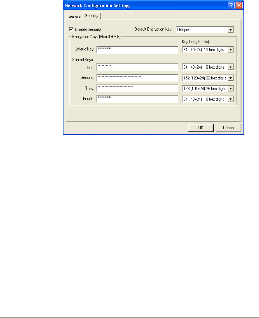
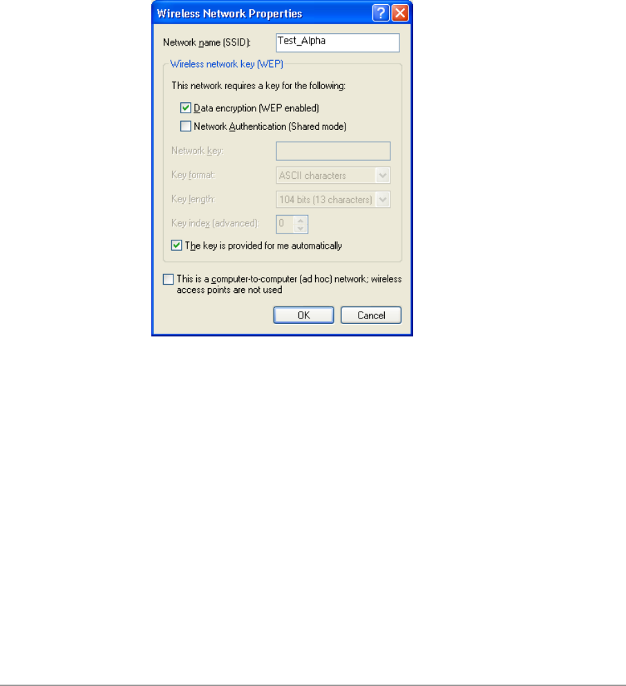
2. If the network requires WEP, then the “Data encryption (WEP enabled)”
check box is selected by default in Wireless Network Properties. Select
the “The key is provided for me automatically” check box if the WEP key
is automatically provided for you. The driver will then use the Default
Encryption key from the current D-Link NCP configuration profile
irrespective of the network name. You may choose to enter the WEP key
by clearing this check box and manually entering the network key and
key length. Note that the key format must be hexadecimal digits and the
key length is limited to 104-bit in Windows XP, as opposed to 128-bit key
supported by D-Link NDIS driver in the NCP configuration interface. If the
network that you are connecting to requires 128-bit WEP key, then it is
recommended that you disable Windows XP automatic wireless network
configuration and use D-Link NCP configuration instead.
5-24
Ad hoc mode
To connect to an existing computer-to-computer (ad hoc) network:
1. Click the ad hoc network name under “Available networks” in the
Wireless Networks tab, and click Configure.
5-25
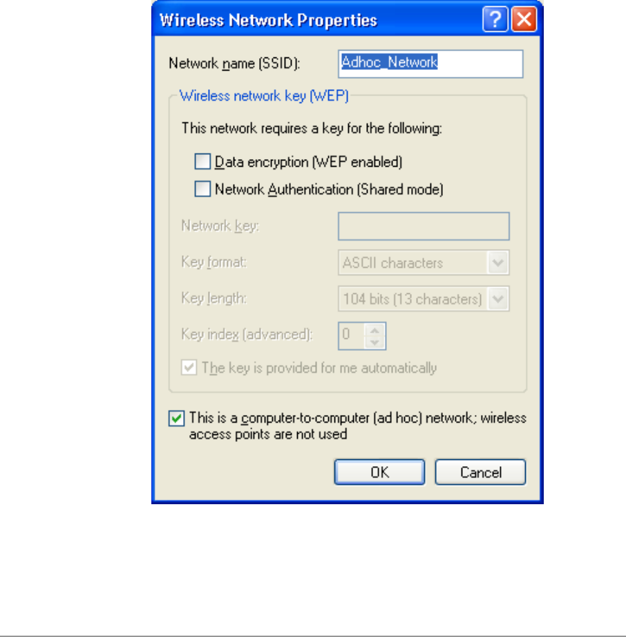
2. In Wireless Network Properties, the “This is a computer-to-computer (ad
hoc) network; wireless access points are not used” check box is selected
by default. You may choose to enable WEP by selecting the “Data
encryption (WEP enabled)” check box and the “Network Authentication
(Shared mode)” check box. Select the “The key is provided for me
automatically” check box if the shared key is automatically provided for
you. The driver will then use the Default Encryption key from the current
D-Link NCP configuration profile irrespective of the network name.
You may choose to enter the shared key by clearing this check box and
enter the key and key length manually. Note that the key format must be
hexadecimal digits and the key length is limited to 104-bit in Windows XP
as opposed to 128-bit key supported by D-Link NDIS driver in the NCP
configuration interface. If the network that you are connecting to requires
128-bit WEP key then it is recommended that you disable Windows XP
automatic wireless network configuration and use D-Link NCP
configuration instead.
5-26
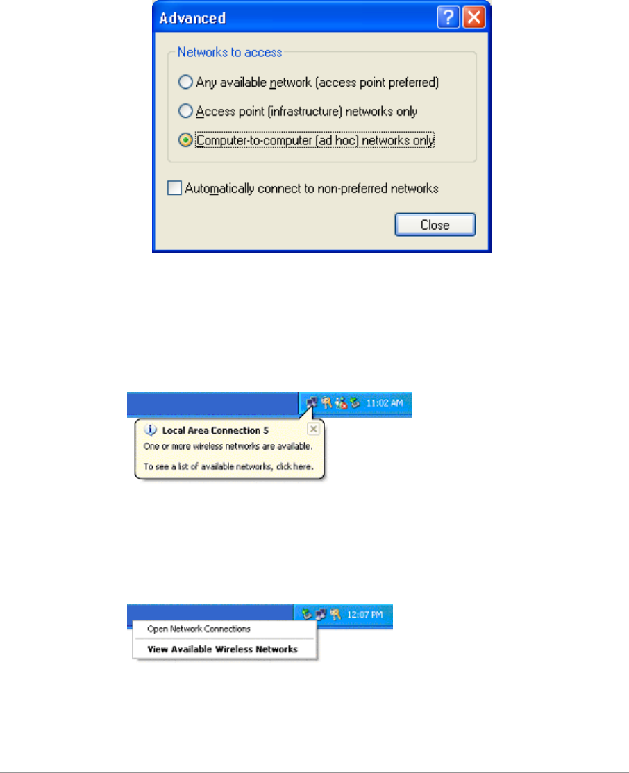
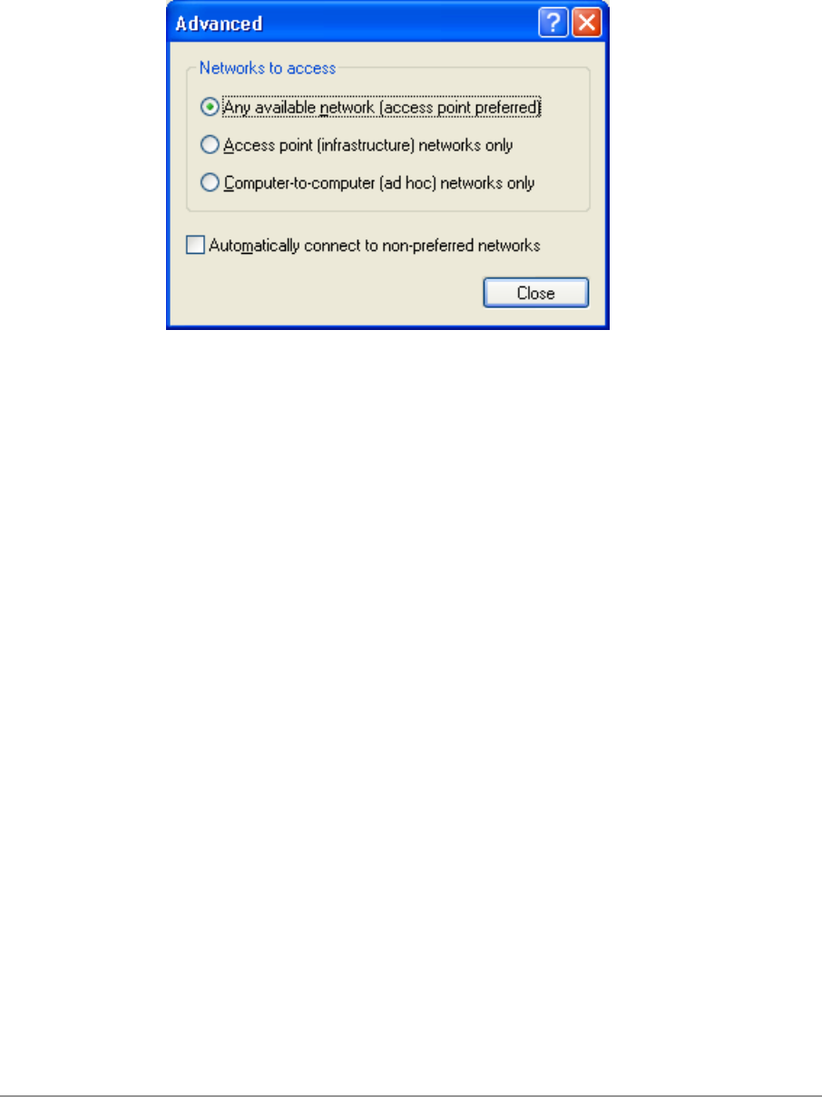
3. If you want to connect to an ad hoc network, but both ad hoc and
infrastructure networks are within range of your computer, then click
Advanced in the Wireless Networks tab and then select “Computer-to-
computer (ad hoc) networks only”. Note that if you want the station to
start its own ad hoc network, the “Computer-to-computer (ad hoc)
networks only” option should be selected. There should be no network
active from the preferred list and the “Automatically connect to non-
preferred networks” check box should be cleared.
Connect to an Available Wireless Network
When there is more than one available network detected by Windows XP, the
OS will prompt the user to select and connect to a preferred network.
To connect to an available wireless network, right-click the network
connection icon in the notification area, and then click “View Available
Wireless Networks”.
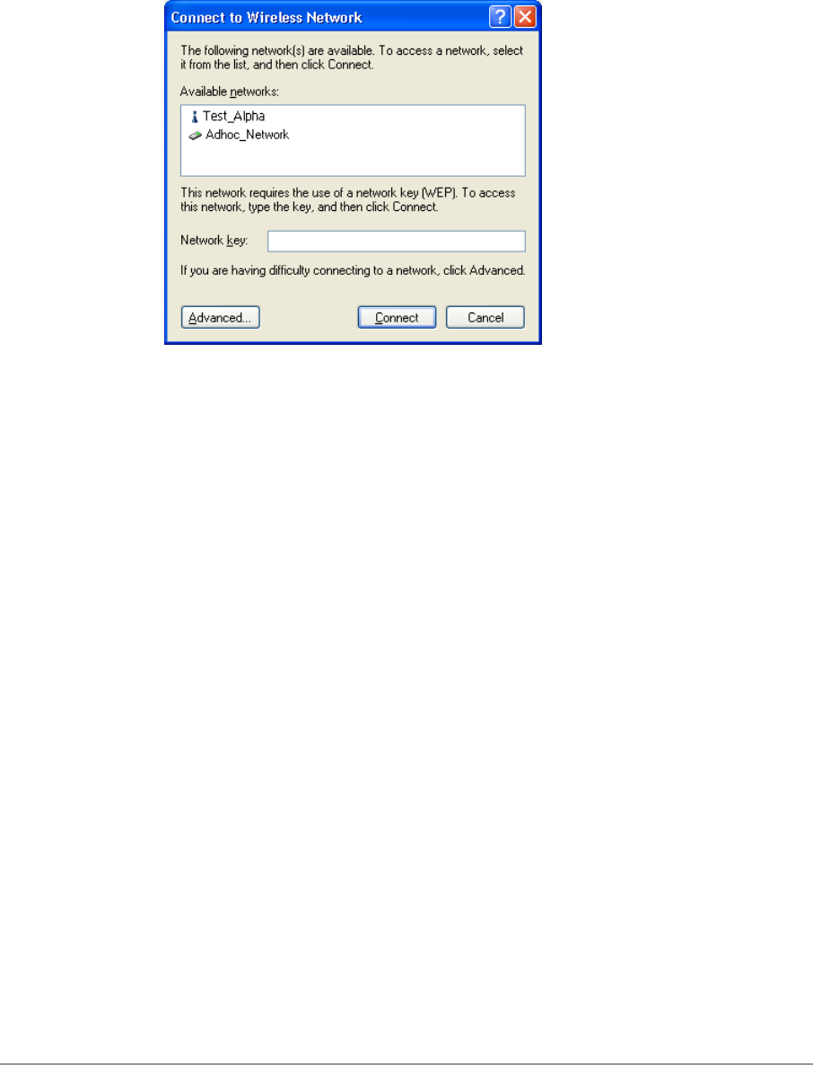
5-27
In Connect to Wireless Network, under “Available networks”, select the
wireless network that you want to connect to. If a network key is required and
is automatically provided for you, then leave “Network key” blank. If the
network key is not automatically provided for you, then type the key in
“Network key”. Click Connect to establish the network connection.
5-28
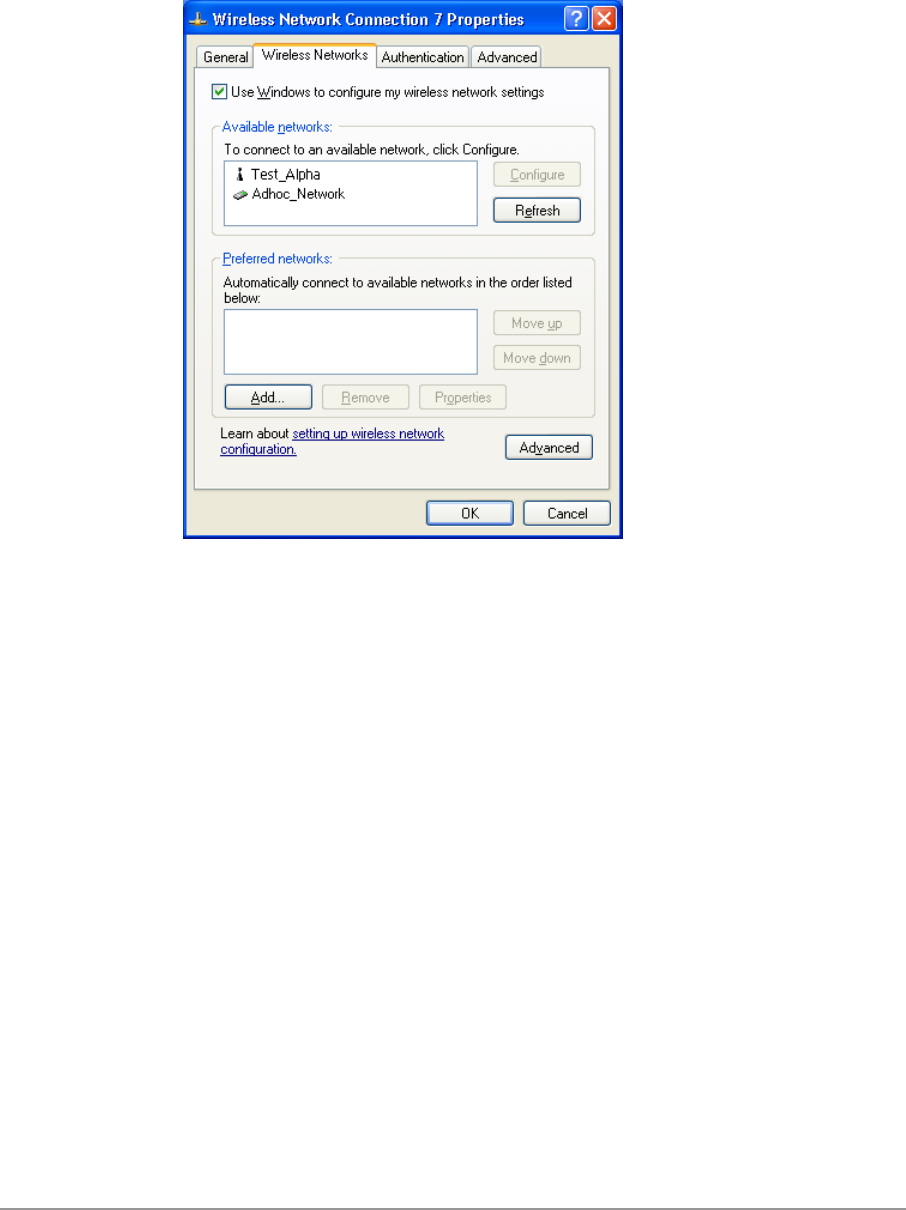
If you are either unable to make a connection to the wireless network that
you selected or need to configure additional wireless network connection
settings, click Advanced in Connect to Wireless Network, and the Wireless
Networks tab will appear.
5-29
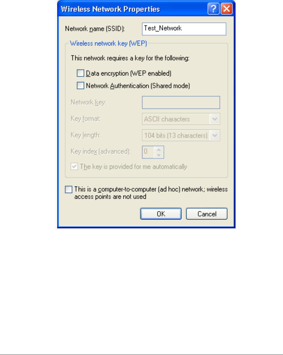
You can configure a new wireless network connection by clicking Add, and
specifying the network name (SSID) in Wireless Network Properties, and the
wireless network key settings, if needed. If the network connection that you
are configuring is an ad hoc network, then select “This is a computer-to-
computer (ad hoc) network; wireless access points are not used” check box.
The network will be added under “Preferred networks” in the Wireless
Networks tab.
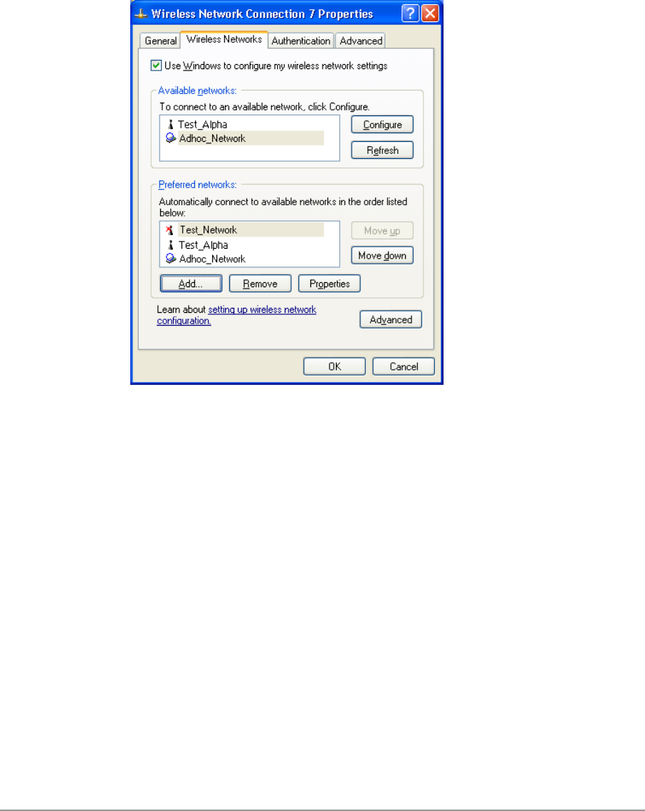
5-30
You can change the order of the preferred networks by selecting the wireless
network that you want to reposition on the list, and then clicking Move up or
Move down. You can change the wireless network connection settings of a
preferred network by selecting the wireless network, clicking Properties, and
then changing the settings as needed. To remove a wireless network from
the list of preferred networks, select the wireless network that you want to
remove, and then click Remove.
5-31
If a network is not defined in the preferred networks list, but you know it is
available and you want to automatically connect to it, then click Advanced in
the Wireless Networks tab, and select the “Automatically connect to non-
preferred networks” check box.

5-32

6-1
6
Windows NT 4.0
Driver Installation and TCP/IP Setup
Windows NT 4.0 does not support Plug-and-plug. Therefore, the D-Link NDIS
driver installation uses an approach that is different from the installation used
in other Operating Systems. In order to install D-Link DWL-A650 Wireless
Network Adapter in Windows NT 4.0 with Service Pack 6, a PC Card utility
called CardWizard is used. If your computer system does not have
CardWizard utility pre-loaded, then you can purchase it from SystemSoft
Corporation (www.systemsoft.com) or you can download a 14-day evaluation
copy from ftp://www.systemsoft.com/pub/Wn51tren.exe. Note that
CardWizard requires Windows NT 4.0 Build 1381 (Service Pack 6) installed
in order to function correctly. Please install Service Pack 6 if your Windows
NT 4.0 is not updated.
After CardWizard utility is loaded, insert the D-Link DWL-A650 Wireless
Network Adapter into a 32-bit CardBus slot, and follow these steps to install
the NDIS driver:
1. CardWizard will detect the insertion of the D-Link CardBus card and show
the following screen. Click Correct to continue.
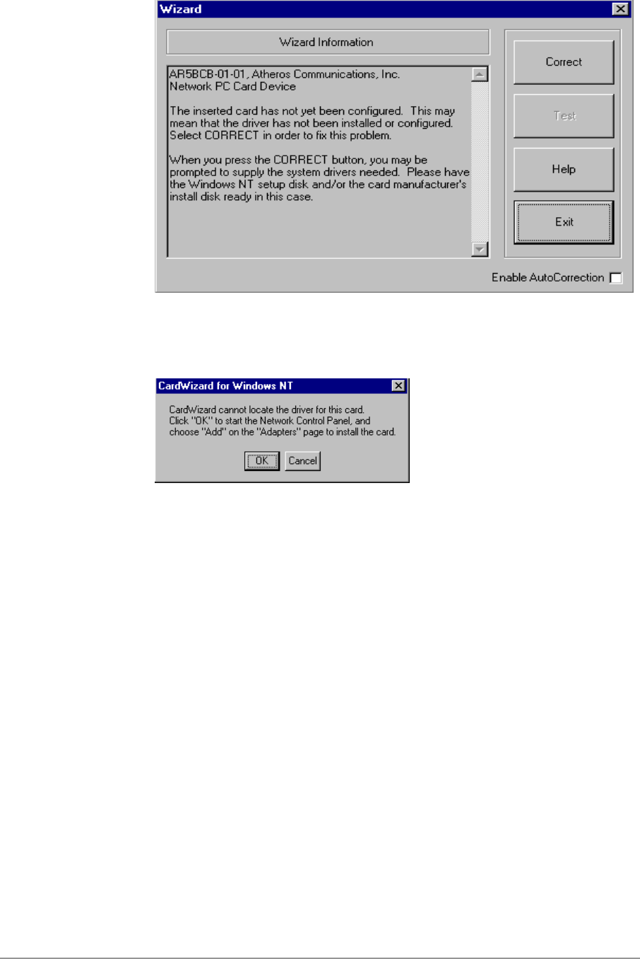
6-2
2. Click OK to continue.
3. Windows NT 4.0 Network Properties windows displays. Click Add to
continue.
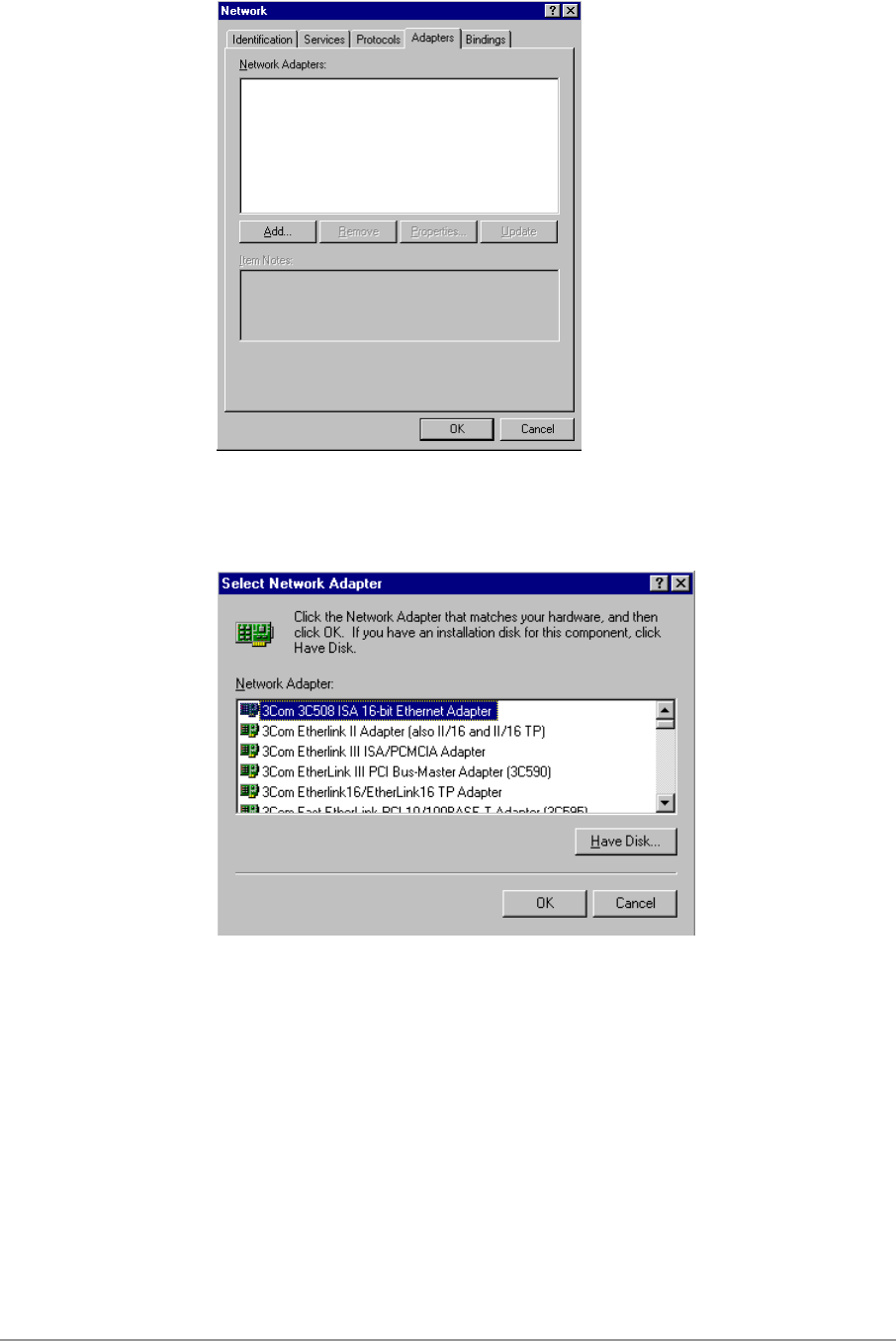
6-3
4. Click Have Disk.
5. Manually enter the location of where the D-Link NDIS 4.0 driver is
located. For example, D:\NDIS\BIN\PRODUCTION\NDIS4. Click OK to
continue.
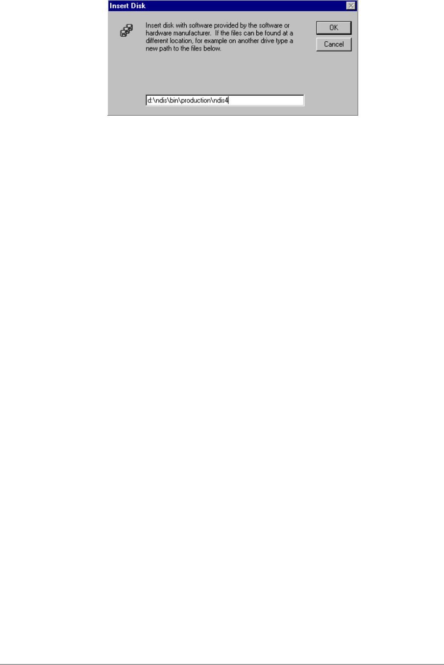
6-4
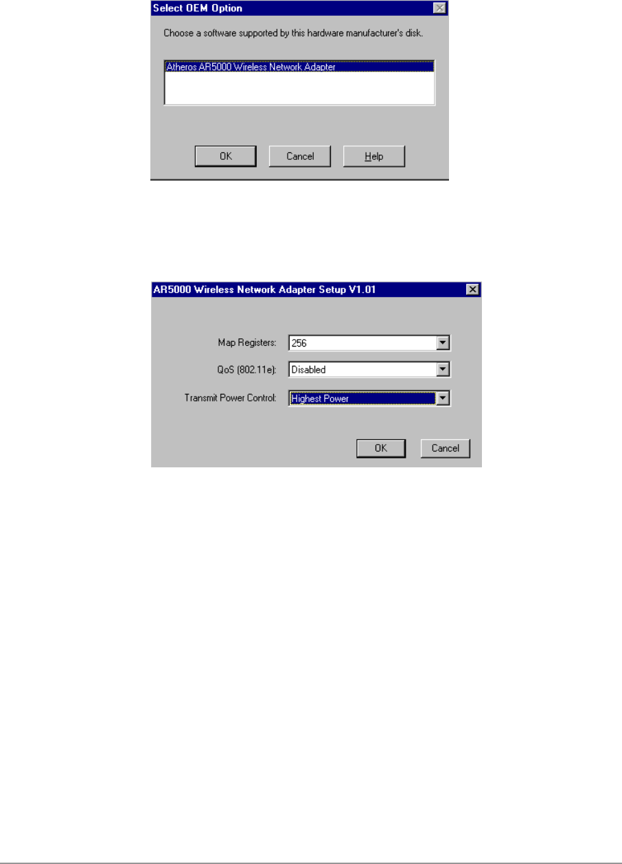
6-5
6. Make sure D-Link DWL-A650 Wireless Network Adapter is selected.
Click OK to continue.
7. Set Map Registers, QoS, and Transmit Power Control to default values
and click OK.
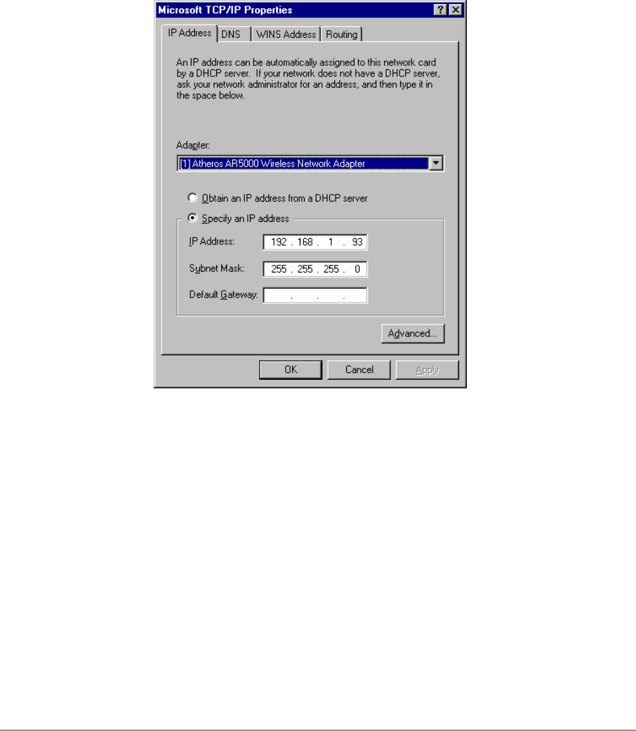
6-6
8. Windows NT 4.0 binds TCP/IP protocol to D-Link DWL-A650 Wireless
Network Adapters and TCP/IP properties have to be entered. Depending
on the type of network the station connects to, Gateway and DNS
Configuration information may also be required. IP configuration
information (DHCP or assigned IP address, Gateway and DNS server IP
addresses) is usually obtained from the corporate IT staff. For a simple
demonstration, the station is assigned a static IP address. Choose
“Specify an IP address” and enter an IP address and subnet mask.
Assigning an IP address and subnet mask allows the station to interact
with the AP or other stations in the same IP subnet. Click OK to complete
the TCP/IP configuration.
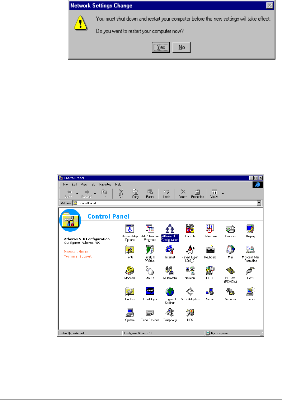
6-7
9. Restart the system for the changes to take effect.
Device Configuration
Configuration of the D-Link DWL-A650 Wireless Network Adapter can be
done through the D-Link NIC Configuration Control Panel applet provided by
D-Link. Similar to Windows 2000, the device can be set to work in one of two
modes, either infrastructure mode or ad hoc mode. See Section “Device
Configuration” beginning on page 2-17 for more details on these network
connection types.
Start D-Link NIC Configuration utility from the Control Panel.
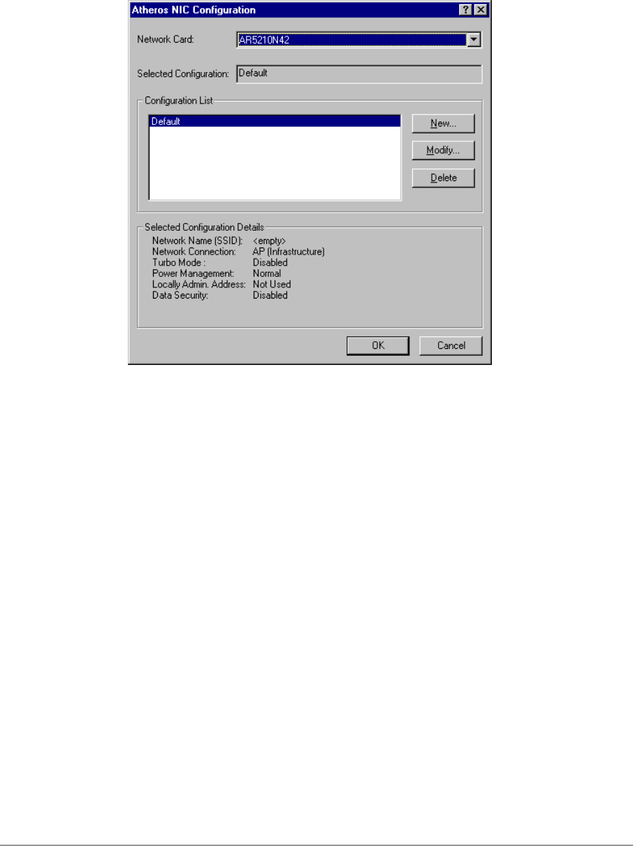
6-8
Select one of the configuration(s) under the configuration list and click Modify
or click New, and follow the Section “Infrastructure Mode” on page 6-8 and
Section “Ad Hoc Mode” on page 6-11 to set up the station to work in
infrastructure mode and ad hoc mode.
Infrastructure Mode
This section defines the process of configuring an D-Link DWL-A650
Wireless Network Adapter in infrastructure mode. Refer to Section “Device
Configuration” beginning on page 2-17 for detailed descriptions of each
option in the Network Configuration Settings.
1. Under the “General” tab, make sure the “Locally Administered Address”
checkbox is unchecked. Use the following information as a guideline to
choose the values of each field in the configuration window:
− Configuration Name: This field identifies the configuration. This name
must be unique. Configuration names are case insensitive. For
example, “AP”.
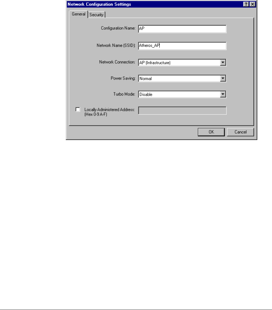
6-9
− Network Name (SSID): This is the name of the IEEE 802.11a
wireless network. For example, “D-Link_AP”. This field has a
maximum limit of 32 characters. If this field is left blank, the STA will
connect to the AP with the best signal strength.
− Network Connection: AP (Infrastructure).
− Power Saving: This field allows the configuration of power
management options. The options are Off, Normal, and Maximum.
− Turbo Mode: This field enables or disables D-Link Turbo mode.
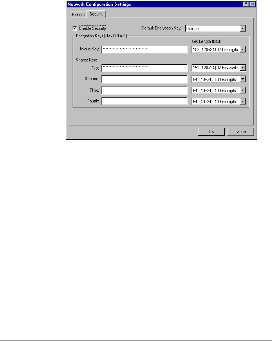
6-10
Usually, infrastructure mode is used in an enterprise environment where
APs are installed and maintained by corporate IT staff. Much of the data
in the enterprise network is confidential. It is important to configure
security to make sure only stations with appropriate keys can receive
sensitive data. The D-Link DWL-A650 Wireless Network Adapter and
NDIS driver support key lengths of 40-bits, 104-bits and 128-bits.
Typically, the appropriate encryption and decryption keys will be supplied
by the corporate IT staff.

6-11
Ad Hoc Mode
This section defines the process of configuring an D-Link DWL-A650
Wireless Network Adapter in ad hoc or IBSS mode. Refer to Section “Ad Hoc
Mode” on page 2-23 for detail descriptions of ad hoc operation.
1. Similar to the set up of AP Infrastructure mode described in the previous
section, ad hoc mode is also configured by changing the options in
“Network Configuration Settings” window. Use the following information
as a guideline to choose the values of each field in the configuration
window:
− Configuration Name: This field identifies the configuration. This name
must be unique. Configuration names are case insensitive. For
example, “Ad Hoc”.
− Network Name (SSID): A Network Name is mandatory for ad hoc
mode. The SSID for all stations in a single ad hoc network must be
the same.
− Network Connection: Ad Hoc.
− Power Saving: Power saving mode is not currently supported in an ad
hoc network.
− Turbo Mode: All stations participating in the ad hoc network must
have the same rate setting.
− Locally Administered Address: This field defines the locally
administered MAC address (LAA). To enter a value in the address
field, the check box needs to be selected.
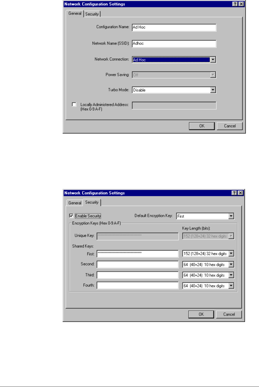
6-12
2. You may optionally set up security features, but it is not typically a
requirement, since the duration of the ad hoc network tends to be limited.
Currently, only shared key security is supported in ad hoc mode. Future
D-Link software implementations will provide unique key support.
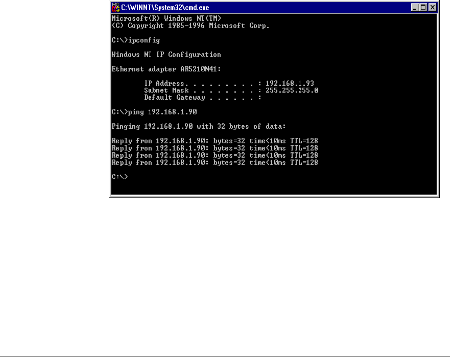
6-13
3. In ad hoc mode, a station will scan the air for an existing BSS. If no BSS
is found, the station will establish a BSS for other stations to join. When
other stations scan the air and find an established BSS in place, they join
that BSS to form an ad hoc network. If a specific set of stations requires
ad hoc network connectivity, it is recommended to have one station
establish a BSS first before configuring the remaining stations. This will
prevent the scenario of several stations trying to form a BSS at the same
time, which may result in multiple singular BSSs being established rather
than a single BSS with multiple stations.
Verify Connection
You may use LinkMon utility to monitor the operating status of D-Link DWL-
A650 Wireless Network Adapter once the STA is connected. Please refer to
Chapter 7 for descriptions of LinkMon utility. If the STA is configured properly
then you will be able to perform ping test as well as other network
applications that a wired Ethernet device can perform.
1. Choose Start > Programs > Accessories > Command Prompt to open the
command prompt window. Type “ipconfig” to determine if the TCP/IP
configuration has taken effect. To test IP connectivity in ad hoc or
infrastructure mode, use the “ping <ipaddress>” command.
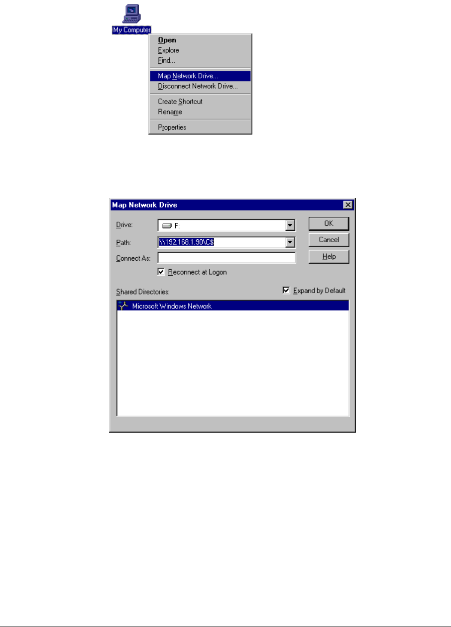
6-14
2. To map the drive on another machine to your computer, right-click “My
Computer” and click “Map Network Drive….”
3. Specify the path of a network-shared folder.
4. After mapping the drive, you can perform file transfers, video streaming,
and all other network data transfers that are normally performed with
wired 10/100 Ethernet connections.
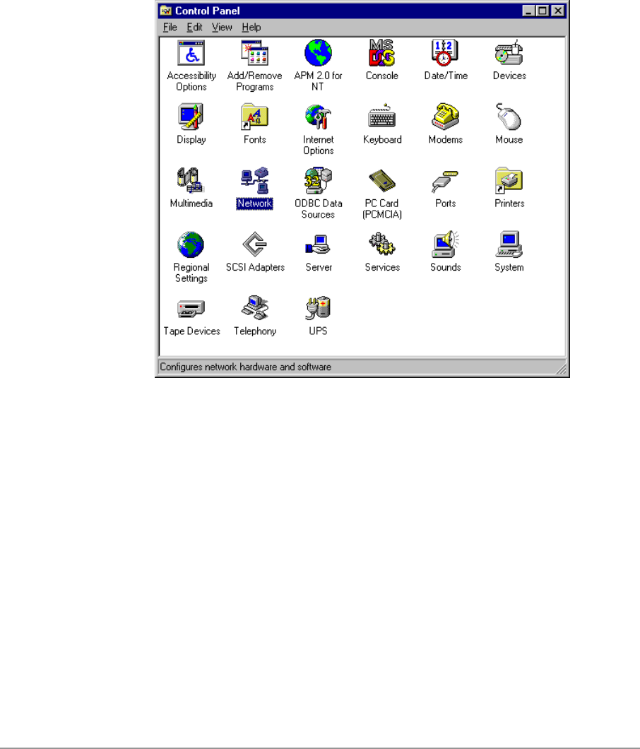
6-15
Driver Uninstallation
This section provides uninstallation procedures for removing the D-Link NDIS
driver from the system.
1. To remove the NDIS driver from the system, go to Control Panel and
open Network properties.
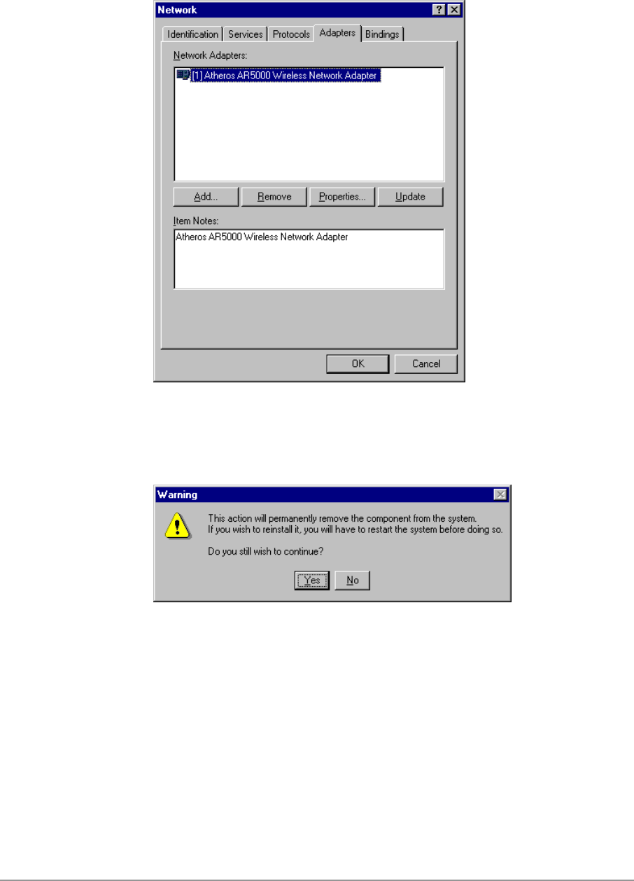
6-16
2. Under the Adapters tab, choose D-Link DWL-A650 Wireless Network
Adapter and click Remove.
3. Click OK to confirm the removal of the D-Link DWL-A650 Wireless
Network Adapter.
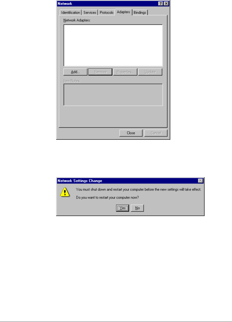
6-17
4. D-Link DWL-A650 Wireless Network Adapter is no longer listed under the
Adapters tab. Click Close to continue.
5. Restart the system to complete the un-installation of D-Link NDIS 4.0
driver.

7-1
7
LinkMon
Installation
LinkMon is a Graphical User Interface (GUI) program that provides detailed
operational status and statistics for the D-Link DWL-A650 Wireless Network
Adapter. The LinkMon executable file, linkmon.exe, is included on the D-Link
Release Version Error! Reference source not found. CD, and is in the folder
\ndis\bin\production\. Copy this file from the CD to a local drive for execution.
Since Windows 98 SE does not have native support for WMI, which is
required to make LinkMon work correctly, an upgrade from Microsoft is
needed. Use the procedures described in the following section to acquire and
install the necessary WMI module from Microsoft. This is only required for
Windows 98 SE installations.
1. Download WMI installer from Microsoft (wmi9x.exe) and save it to your
hard disk.
2. Execute WMI installer by double-clicking wmi9x.exe.

7-2
7-3
3. Click Next to continue.
4. Click “I accept this agreement” and then click Next to continue.
7-4
5. Click Next to continue.
6. The installer now installs files to the SYSTEM directory.
7. The system must be rebooted for the WMI installation files to become
effective. When the system completes the rebooting process, launch
LinkMon.
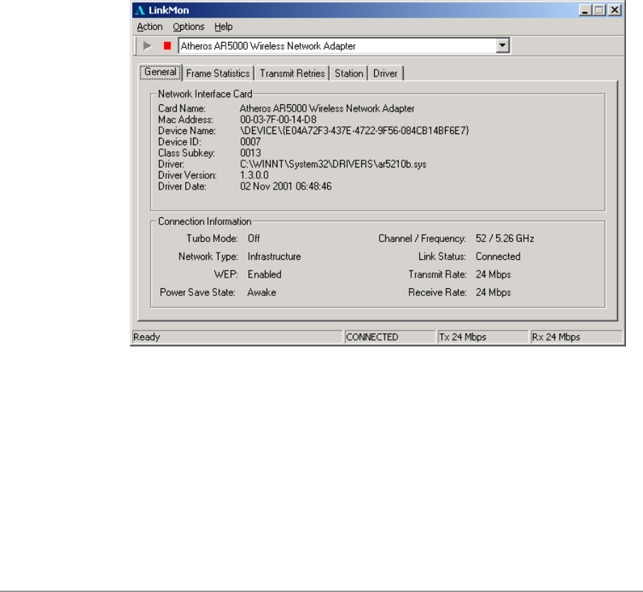
7-5
Features
There are five tabs in LinkMon used to display STA information:
General tab
Frame Statistics tab
Transmit Retries tab
Station tab
Driver tab
Under the General tab of the LinkMon program property sheet is general
information about the program and its operations.
Under the Frame Statistics tab is statistical information showing the number
of frames being sent and received, retry count on frames sent, frame
checksum error counts for received frames, and receive signal strength
indicator (RSSI) information. These fields are described in the Station
Programmer’s Guide under Appendix A as OIDs. LinkMon supports most of
the OIDs listed in that section.
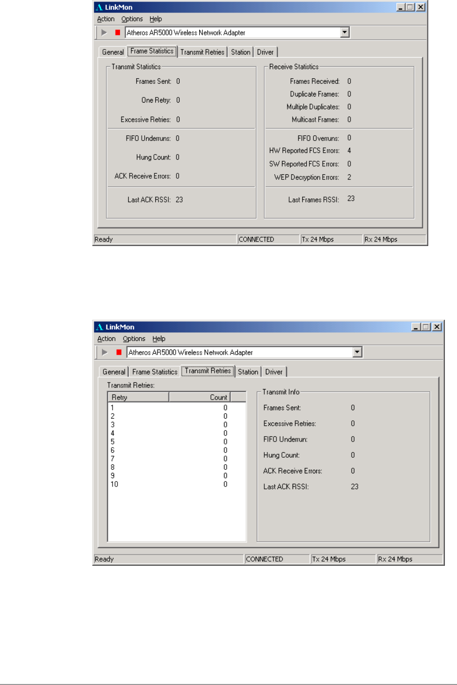
7-6
Under the Transmit Retries tab is detailed transmit retry statistical information
for transmitted frames.
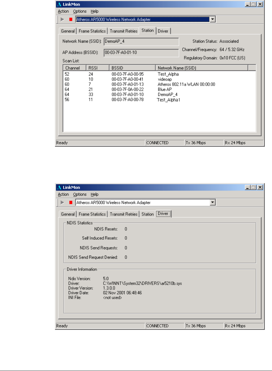
7-7
Under the Station tab is detailed BSS information including SSID, BSSID,
association status, operating channel frequency, and information about
scanned APs.
Under the Driver tab is statistical data pertaining to NDIS driver operation.
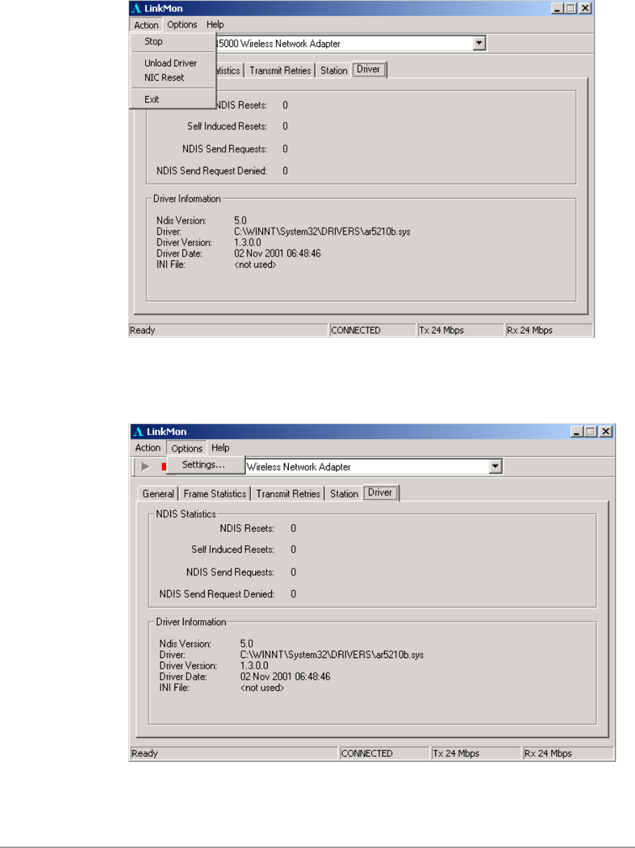
7-8
The Action menu enables a NDIS driver unloading and reloading, and
network interface card (NIC) reset. Note that driver unload option is not
available in Windows Me, Windows 98SE, and Windows NT 4.0. NIC reset is
also not available in Windows NT 4.0.
On the Options menu, choose Settings….
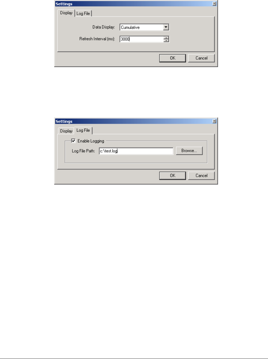
7-9
Under the Display tab, you can select the data display modes of “Cumulative”
or “Relative.” “Cumulative” mode displays statistical LinkMon data collected
from the beginning of driver load. “Relative” mode displays differences in the
statistical data since the last update.
Under the Log File tab, the logging function can be enabled to log to a file the
statistical information collected by the LinkMon utility, for later reference or
post processing by an application such as Microsoft Excel.

8-1
8
RFSilent
This chapter describes the RFSilent application that allows you to enable or
disable the RF Signal (radio) on all D-Link STA Reference Designs. The
RFSilent is a Windows-based application that appears in the right-hand
corner of your Windows taskbar.
System Requirements
The RFSilent application communicates with most Windows applications
using Windows Management Instrumentation (WMI). For Windows NT 4.0,
RFSilent communicates through the Input and Output Control (IOCTL)
mechanism.
If you are using Windows 98SE, WMI does not come pre-installed and you
must install it prior to using RFSilent. Refer to the following procedure to
acquire and install the required WMI module from Microsoft.
Windows 98SE Environment
If you want to use the RFSilent application in a Windows 98SE environment,
you must install WMI.
Follow these steps to install WMI:
1. Download the WMI installer (wmi9x.exe) from Microsoft and save it to
your hard disk.
2. Execute the WMI Installer by double-clicking wmi9x.exe.
3. Click Next to continue.
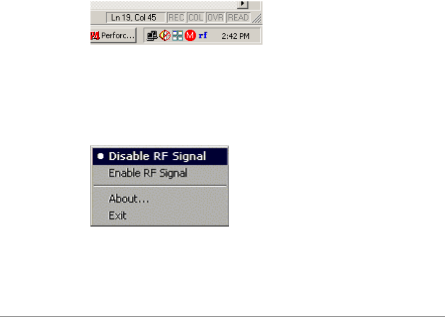
8-2
4. Click “I accept this agreement” and then click Next to continue.
5. Click Next to continue.
The installer now copies the necessary files to the SYSTEM directory.
6. Reboot the system.
RFSilent Setup
The RFSilent application allows you to enable or disable D-Link STA
References Designs. You can enable or disable the RFSilent application
through user-defined settings. Refer to a description of driver parameters in
the AP Programmer’s Reference Guide.
Operation
The RFSilent application is a Windows-based application that, once enabled,
appears as an icon (RF) in the right-hand corner of your Windows taskbar
(see Figure 8-1). You can automatically launch RFSilent at system boot-up
by entering a shortcut statement in the Startup folder.
Figure 8-1. RFSilent Icon
Position your cursor over the RF Icon in your toolbar and use your right or left
mouse button to display the RFSilent application selections (see Figure 8-2).
The radio button on the side of menu selections indicates the current state of
the RFSilent application.
Figure 8-2. RFSilent Menu Selections
Refer to Table 8-1 for a description of the RFSilent menu selections.

8-3
Table 8-1. RFSilent Menu Descriptions
RFSilent Menu Item Descriptions
Disable RF Signal Use this selection to
disable D-Link STA
Reference Design.
Enable RF Signal Use this selection to enable
D-Link STA Reference
Design.
About Displays copyright, version
information, and the build
date for the RFSilent
application.
Exit Quits the RFSilent
application.

9-1
9
Troubleshooting
This chapter provides solutions to common problems that usually occur
during the installation and operation of the D-Link DWL-A650 Wireless
Network Adapter. Read the following descriptions if you are having problems.
If you cannot find an answer here, please contact an D-Link field application
engineer for assistance.
1. My computer does not recognize the D-Link CardBus reference
card.
Make sure the CardBus card is properly inserted into a 32-bit CardBus
slot. If Windows does not detect the hardware upon insertion of the card,
the system could have a previous D-Link NDIS driver installed. Remove
the old driver and try again.
2. The D-Link DWL-A650 Wireless Network Adapter does not work
properly after the driver is installed.
Re-insert the CardBus card into the slot. A beep should be heard if the
adapter is properly inserted. Go to Device Manager and make sure the D-
Link DWL-A650 Wireless Network Adapter exists under the network
adapters device node. If you see the yellow exclamation mark then there
are conflicting resources. In this case, make sure the computer system
has a free IRQ and make sure you have installed the proper driver.
Uninstall the driver, restart the system, and repeat the driver installation
steps if necessary.
3. Stations cannot associate in ad hoc mode.
Make sure the same service set identifier is specified for all stations that
need to join the same ad hoc network. Set up one station to establish a
BSS and wait briefly before setting up other stations. This prevents
several stations from trying to establish a BSS at the same time, which
can result in multiple singular BSSs being established, rather than a
single BSS with multiple stations associated to it.

9-2
4. The station cannot access the Internet in the infrastructure
configuration.
Make sure the station is associated and joined with the AP. If Wired
Equivalent Privacy (WEP) security is enabled on the AP, the station must
have the proper WEP keys specified. Also make sure TCP/IP properties
are correctly configured.

A
Channel and Data Rate
Selection
This section provides basic information for selecting fixed data rate and
channel frequency in the NDIS driver. This becomes necessary if you want to
test the D-Link Wireless Network Adapter at a specific channel with the rate
adaptation controls turned off.
To select channel frequency and data rate in the Windows environment with
NDIS driver installed:
1. Choose Start > Run, and type “regedit” to open Registry Editor.
2. For Windows 2000 and Windows XP, locate the following registry key,
and select Find from the Edit menu:
HKEY_LOCAL_MACHINE\SYSTEM\CurrentControlSet\
For Windows 98SE and Windows Me, locate the following registry key,
and select Find from the Edit menu:
HKEY_LOCAL_MACHINE\System\CurrentControlSet\
3. Type “clist” and click Find Next to find the registry key. Note that if you
have multiple instances of the D-Link Wireless Network Adapter installed,
for example, the NDIS driver is installed more than once, then you will
need to click Find Next to locate the current instance of the device that is
in use.

4. Double-click on clist and enter the channel number in the “Value Data”
field. Enter the IEEE channel number from the following table. For
example, enter 40 to select channel frequency of 5.20 GHz. The channel
numbers follow the IEEE format where:
Channel Frequency (in GHz) = 5 + 0.005 * (Channel Number)
Channel Number Channel Frequency Regulator Domain
26 5.13 GHz N/A (not calibrated)
28 5.14 GHz N/A (not calibrated)
30 5.15 GHz N/A (not calibrated)
32 5.16 GHz N/A (not calibrated)
34 5.17 GHz TELEC
36 5.18 GHz FCC
38 5.19 GHz TELEC
40 5.20 GHz FCC
42 5.21 GHz TELEC
44 5.22 GHz FCC
46 5.23 GHz TELEC
48 5.24 GHz FCC
50 5.25 GHz N/A (not calibrated)
52 5.26 GHz FCC
54 5.27 GHz N/A (not calibrated)
56 5.28 GHz FCC
58 5.29 GHz N/A (not calibrated)
60 5.30 GHz FCC
62 5.31 GHz N/A (not calibrated)
64 5.32 GHz FCC
66 5.33 GHz N/A (not calibrated)
68 5.34 GHz N/A (not calibrated)
70 5.35 GHz N/A (not calibrated)
72 5.36 GHz N/A (not calibrated)
74 5.37 GHz N/A (not calibrated)
76 5.38 GHz N/A (not calibrated)
78 5.39 GHz N/A (not calibrated)
80 5.40 GHz N/A (not calibrated)

Channel Number Channel Frequency Regulator Domain
82 5.41 GHz N/A (not calibrated)
84 5.42 GHz N/A (not calibrated)
86 5.43 GHz N/A (not calibrated)
5. To select the fixed data rate at which you want the station to transmit,
double-click on rateCtrlEnable from the same registry key location where
clist resides, and enter 0 to disable rate adaptation. Double-click on
TransmitRate and enter the value specified in the following table to select
the actual data rate. For example, enter 3 for 18 Mbps.
Rate Number Data Rate
0 6 Mbps
1 9 Mbps
2 12 Mbps
3 18 Mbps
4 24 Mbps
5 36 Mbps
6 48 Mbps
7 54 Mbps
6. For the changes to take effect:
− If you are running Windows 98SE or Windows Me, close Register
Editor and restart the systems.
− If you are running Windows 2000 or Windows XP, unload and load
the driver from LinkMon.
7. To undo these changes and go back to normal operation where the
channel and data rate are dynamically set, change rateCtrlEnable to 1
and clear the clist value.