D Link AP2330A1 Wireless N300 Single Band PoE Access Point User Manual
D Link Corporation Wireless N300 Single Band PoE Access Point
D Link >
User Manual

Wireless N300
Single Band Gigabit PoE Access
Point
Use
r
Manual

T
able
of
C
o
n
t
e
n
ts
2
D
-
Link
D
A
P
-
2330
U
ser
M
anual
Table
of
C
on
t
ents
P
r
oduc
t
O
v
er
vie
w
......................................................................
4
Introduction
...................................................................................
4
F
ea
tur
es
............................................................................................
5
Package
C
on
t
ents
.........................................................................
6
S
yst
em
R
equir
ements
.................................................................
6
Hardware Overview
..................................................................
7
LEDs
...................................................................................................
7
Connections
...................................................................................
7
Basic
I
nstalla
tion
........................................................................
8
Hardware
S
etup
............................................................................
8
Method
1 -
PoE
with
PoE
S
wit
ch
.....................................
8
Method 2 -
PoE
without
PoE
S
wit
ch
or
R
out
er
................
9
Method
3 -
No
P
oE
..............................................................
10
Web User I
n
t
er
face
.................................................................
11
Wireless
..........................................................................................
12
Access
P
oin
t
Mode
.............................................................
12
WDS
with
AP
Mode
............................................................
14
WDS Mode
............................................................................
16
Wireless
Clien
t
Mode
.........................................................
18
Wireless
S
ecur
it
y
.................................................................
19
Wired
E
quiv
alen
t
Privacy (WEP)
..............................
19
Wi-Fi
P
r
ot
ec
t
ed
Access (WPA
/
W
P
A2)
....................
20
802.1x A
uthentica
tion
.................................................
22
LAN
..........................................................................................
23
IPv6
..........................................................................................
24
Advanced
S
ettings
.....................................................................
25
P
er
f
or
manc
e
.........................................................................
26
Wireless Resource
C
on
tr
ol
.......................................................
28
M
ulti-SSID
..............................................................................
30
VLAN
........................................................................................
32
VLAN
List
..........................................................................
32
P
or
t
List
.............................................................................
33
Add/Edit
VLAN
...............................................................
34
PVID
S
ettings
..................................................................
35
I
ntrusion
.................................................................................
36
S
chedule
................................................................................
37
Internal
RADIUS
S
er
v
er
.....................................................
38
ARP
Spoofing Prevention
................................................
39
Bandwidth Optimization
.................................................
40
AP
A
rr
a
y
..................................................................................
42
AP Array
S
can
.................................................................
42
C
onfigur
a
tion
S
ettings
................................................
43
A
ut
o
-RF
.............................................................................
47
Load Balance
..................................................................
48
Captive
P
ortal
.......................................................................
49
Authentication
S
ettings
-
P
assc
ode
.......................
49
Authentication
S
ettings
-
User
Name/Password50
Authentication
S
ettings
-
R
emot
e
R
ADIUS
..........
51
Authentication
S
ettings
-
LD
AP
...............................
52
Authentication
S
ettings
-
POP3
...............................
53

T
able
of
C
o
n
t
e
n
ts
3
D
-
Link
D
A
P
-
2330
U
ser
M
anual
Login Page
Upload
.......................................................
54
Web
R
edir
ec
tion
............................................................
55
DHCP
S
er
v
er
.........................................................................
56
Dynamic Pool
S
ettings
................................................
56
S
ta
tic
Pool
S
etting
........................................................
57
C
urr
en
t
IP
Mapping
List
..............................................
58
F
ilt
ers
.......................................................................................
59
Wireless MAC A
CL
.........................................................
59
WLAN
P
ar
tition
..............................................................
60
Traffic
C
on
tr
ol
...............................................................................
61
Uplink/Downlink
S
etting
.................................................
61
Q
oS
...........................................................................................
62
Traffic
M
anager
....................................................................
63
S
ta
tus
..............................................................................................
64
Device Information
............................................................
65
Clien
t
I
nf
or
ma
tion
..............................................................
66
WDS
Information
Page
.....................................................
67
Channel
A
nalyz
e
.................................................................
68
S
ta
ts
P
age
......................................................................................
69
E
thernet
Traffic
S
ta
tistics
..................................................
69
WLAN Traffic
S
ta
tistics
.......................................................
70
Lo
g
...................................................................................................
71
View
L
og
.................................................................................
71
Log
S
ettings
..........................................................................
72
M
ain
t
enanc
e
S
ec
tion
................................................................
73
A
dministr
a
tion
.............................................................................
74
Limit
A
dministr
a
t
or
............................................................
74
S
yst
em
Name
S
ettings
......................................................
75
Login
S
ettings
......................................................................75
Console
S
ettings
.................................................................
75
SNMP
S
ettings
.....................................................................
76
A
dministr
a
tion
.............................................................................
77
Central WiFiManager
S
ettings
........................................
77
Firmware and
SSL
Upload
................................................
78
C
onfigur
a
tion
File
Upload
...............................................
79
Time and
Da
t
e
S
ettings
....................................................
80
C
onfigur
a
tion
and
S
yst
em
.......................................................
81
S
yst
em
S
ettings
...........................................................................
82
Help
.................................................................................................
83
Knowledge
Base .....................................................................
84
Wireless
Basics
.............................................................................
84
Wireless Installation
C
onsider
a
tions
....................................
85
Troubleshooting
.....................................................................
86
Why can’
t
I
access
the
web-based
configuration
utility?
.....................................................................................
86
W
ha
t
can
I do if I forgot my
passw
or
d?
.......................
86
How
to
check your IP
addr
ess?
......................................
87
How
to
statically assign an
IP
addr
ess?
.......................
88
Technical Specifications
........................................................
89
A
n
t
enna
P
a
tt
ern
.....................................................................
90
C
on
tac
ting
Technical
Suppor
t
..............................................
91
W
arran
t
y
...................................................................................
92
R
eg
istr
a
tion
.............................................................................
98

4
D
-
Link
D
A
P
-
2330
U
ser
M
anual
S
e
c
tion
1
-
P
r
odu
c
t
O
v
e
r
view
P
r
oduc
t
O
v
er
vie
w
I
n
tr
oduc
tion
D-Link
,
an
industr
y
pioneer
in
wir
eless
net
w
or
k
ing
,
introduces
a
solution
f
or
businesses seeking
to
deplo
y
nex
t
gener
a
tion
802.11n
LANs
.
D-Link
unveils
its new DAP-2330, designed specifically for
en
vironmen
ts
with high
traffic
areas such as
air
por
ts
,
c
off
ee
shops
,
shopping
c
en
t
ers
,
sporting v
enues
,
and
school campuses
to
provide secure and manageable dual band wireless network options
for
network administr
a
t
ors
.
Versatile
Access
Point
The DAP-2330 Access
P
oin
t
allows
network
administr
a
t
ors
to deploy a highly
manageable
and
extremely
robust dual band
wireless
net
w
or
k
.
F
or
advanced
installa
tions
,
this
new
high-speed A
cc
ess
P
oin
t
has
in
t
eg
r
a
t
ed
802.3af
P
o
w
er
ov
er
E
thernet
(P
oE)
suppor
t
,
allo
wing
installation of this
devic
e
in
areas
wher
e
power outlets
ar
e
not
r
eadily
a
v
ailable
.
I
n
addition to bridging
802.11b/g/n
wir
eless
net
w
or
ks
,
the
DAP-2330
can
br
idge
to
wir
ed
networks
with
its integrated
Gigabit (10/100/1000Mbps)
E
thernet
por
t
.
Enhanced
P
er
f
ormance
The DAP-2330 delivers reliable wireless performance
with
maximum wireless signal
r
a
t
es
of up to
300Mbps
.
This,
coupled with support for Wi-Fi
Multimedia™ (WMM) Quality
of
S
ervic
e
f
ea
tur
es
,
makes
it
an ideal access
point for
audio
,
video
,
and voice applica
tions
.
S
ecurity
T
o
help
maintain
a
secure
wir
eless
net
w
or
k
,
the
D
AP
-2330
pr
o
vides
the
la
t
est
in
wir
eless
secur
it
y
t
echnolog
ies
b
y
suppor
ting
both
P
ersonal
and
Enterprise
versions of
W
P
A
and
W
P
A2
(802.11i)
with
support
f
or
RADIUS server back
end
.
T
o
fur
ther
pr
ot
ec
t
your
wir
eless
net
w
or
k
,
M
A
C
Address
F
ilt
er
ing
,
Wireless
LAN
segmentation, Disable
SSID
Br
oadcast
,
R
ogue
AP
Detection, and Wireless Broadcast
S
cheduling
are also
included
.
*
Maximum wireless signal
r
a
t
e
derived
from
IEEE
S
tandar
d
802.11g and 802.11n specifica
tions
.
Actual data
throughput will
v
ar
y
.
Network conditions and environmental
fac
t
ors
,
including
volume
of
network
tr
affic
,
building
ma
t
erials
and construction, and network ov
er
head
,
lower actual data
throughput
r
a
t
e
.
Environmental conditions
will
adversely
aff
ec
t
wireless signal
range
.

5
D
-
Link
D
A
P
-
2330
U
ser
M
anual
S
e
c
tion
1
-
P
r
odu
c
t
O
v
e
r
view
F
ea
tur
es
y
Provide
E
thernet
to
Wireless LAN
bridge fully
IEEE
802.3/u compatible
on the
E
thernet
side and
fully
interoperable
with
IEEE
802.11b/g/n
compliant
equipment
y
Compatible
with
IEEE
802.11b
high
r
a
t
e
standard
to
provide wireless 11Mbps data
rate*
y
Compatible
with
IEEE
802.11g higher speed standard
to
provide wireless 54Mbps data
rate*
y
Compatible
with
IEEE
802.11n higher speed standard
to
provide wireless 300Mbps data
rate*
y
Operation
at
2.4~2.5GHz frequency band
to
meet worldwide
regulations
y
Supports
IEEE
802.11b/g/n wireless data encryption
with
64/128-bit
WEP
for security
y
Supports enhanced security
–
WPA-PSK
and
WPA2-PSK, RADIUS
clien
t
,
and Cipher
negotiation
y
A
llow
s
auto fallback data
r
a
t
e
for
r
eliabilit
y
,
optimized
throughput
and transmission
range
y
Web-based configuration and
management
y
Supports 802.3af
P
oE
y
Supports
802.3az
y
Supports one Gigabit
E
thernet
por
t
y
AP
Mode
,
WDS
Mode
,
WDS
with
AP,
and
Wireless
Clien
t
Mode
y
Supports
SNMP
v1,v2,v3
y
Suppor
t
Trap server (SNMP v1,
v2c)
y
Suppor
t
C
en
tr
al
WiFiManager
y
Suppor
t
AP Array and AP Array
S
etup
T
ool
*
Maximum wireless signal
r
a
t
e
derived
from
IEEE
S
tandar
d
802.11g
,
and 802.11n specifica
tions
.
Actual data
throughput will
v
ar
y
.
Network conditions and environmental
fac
t
ors
,
including
volume
of
network
tr
affic
,
building
ma
t
erials
and construction, and network ov
er
head
,
lower actual data
throughput
r
a
t
e
.
Environmental conditions
will
adversely
aff
ec
t
wireless signal
range
.

6
D
-
Link
D
A
P
-
2330
U
ser
M
anual
S
e
c
tion
1
-
P
r
odu
c
t
O
v
e
r
view
Package
C
on
t
en
ts
• DAP-2330 Access
P
oin
t
• Power
Adapter
•
Mounting
P
la
t
e
and
Hardware
•
E
thernet
C
able
• CD
(with
sof
t
w
ar
e
and user
manual)
• Quick Installation
Guide
Not
e:
Using
a
po
w
er
supply
with
a
different
voltage
r
ating
than
the
one
included
with
the
D
AP
-2330
will
cause
damage and
void
the
w
arr
ant
y
for
this
product.
S
y
stem
R
equir
ements
y
Computers
with
W
indo
w
s®,
M
acin
t
osh®,
or
Linux-based operating systems
with
an installed
E
thernet
Adapter
y
Internet
Explorer Version 11.0, Chrome 33, Safari 7,
or
Firefox 28 and above (for web-based
configuration)
7
D
-
Link
D
A
P
-
2330
U
ser
M
anual
S
e
c
tion
1
-
P
r
odu
c
t
O
v
e
r
view
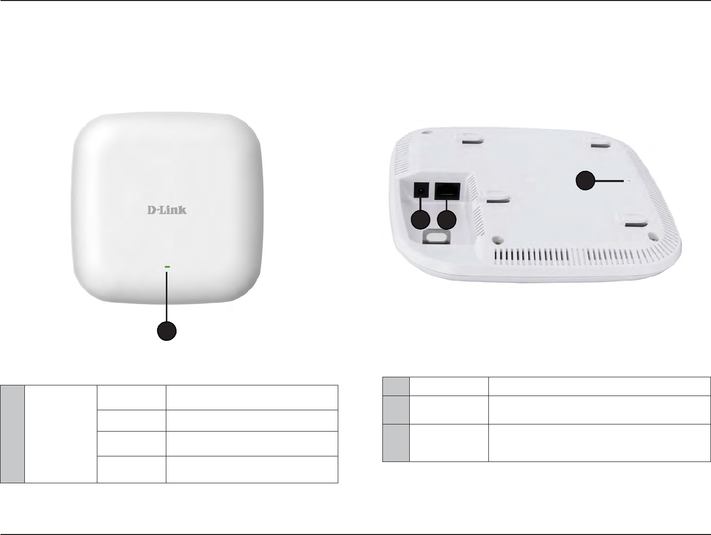
2
Power
R
ec
ept
or
C
onnec
t
the
supplied power adapt
er
.
3
LAN (PoE)
P
or
t
C
onnec
t
to
a Power over
E
thernet
(PoE)
switch
or
router
via
an
E
thernet
cable
.
4
Reset
Button
Press and
hold for five
seconds
to
reset
the
access
point
t
o
the
factory
default
settings
.
Press and
hold for one sec
ond
to reboot the
access poin
t
.
Hardware
Overview
LEDs
C
onnec
tions
4
2
3
1
1
P
o
w
er/S
tatus
S
olid
R
ed
I
ndica
t
es
the
access
point has
malfunc
tioned
.
Blinking
R
ed
This LED
will blink during
boot
-up
.
S
olid
Green
I
ndica
t
es
that the
DAP-2330 is
working
pr
operly
.
Blinking
Green
This
light will blink
green
during data
transmission.
8
D
-
Link
D
A
P
-
2330
U
ser
M
anual
S
e
c
tion
2
-
I
nstall
a
tion
Basic
I
nstalla
tion
Hardware
S
etup
To power the
access poin
t
,
you can use one
of
the
following
3
methods:
Method
1
- Use
if
you have a PoE
switch or r
out
er
.
Method
2
- Use
if
you
do not
have a PoE
switch or router and
do not
have a power
outlet
near the location
of
the access poin
t
.
Method
3
- Use
if
you
do not
have a PoE
switch or router and have a power
outlet
near the location
of
the access poin
t
.
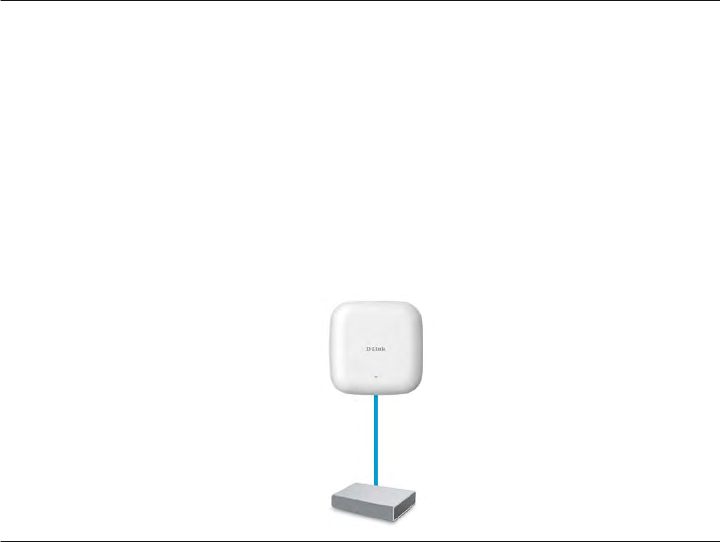
Method 1
-
PoE with PoE
S
wit
ch
1.
C
onnec
t
one end
of
your
E
thernet
cable
to
the LAN (PoE)
port
on the access poin
t
.
2.
C
onnec
t
the other end
into
one
port
on a PoE
switch.
D
AP
-2330
PoE
S
wit
ch
or
R
out
er
9
D
-
Link
D
A
P
-
2330
U
ser
M
anual
S
e
c
tion
2
-
I
nstall
a
tion
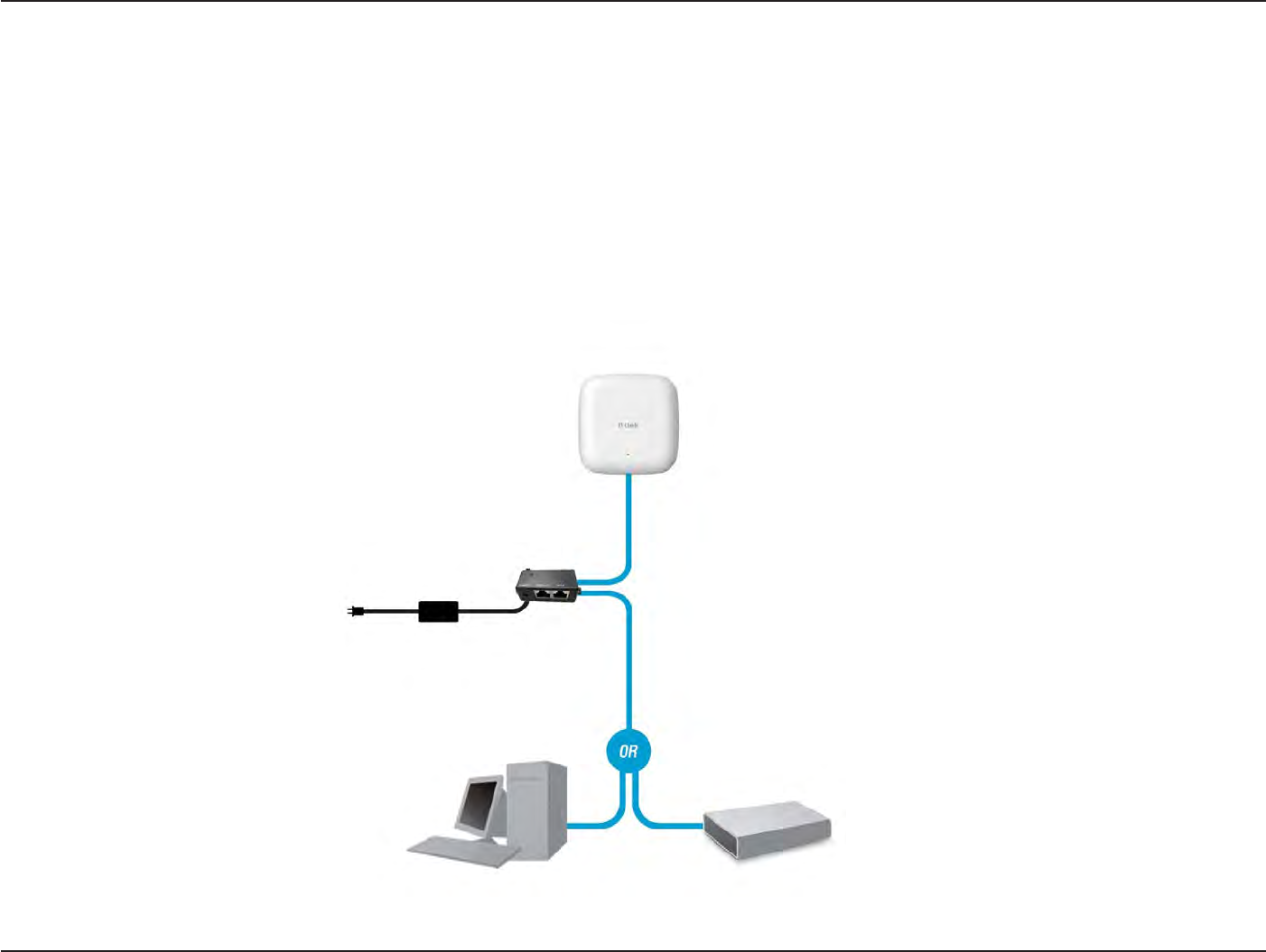
Method
2 -
PoE
without
PoE Switch or
Router
1.
C
onnec
t
one end
of
an
E
thernet
cable
into
the
Data In
port
on the PoE base
unit
and the other end
into
one
port
on your switch,
r
out
er
,
or
c
omput
er
.
2.
C
onnec
t
one end
of
an
E
thernet
cable
into
the
P+Data Out
port
on the PoE base
unit
and the other end
into
the LAN (PoE)
port
on the Access
P
oin
t
.
3. Use
the supplied power adapt
er
.
C
onnec
t
the power adapter
to
the
Power In
receptor on the
PoE
adapt
er
.
4.
C
onnec
t
the power cable
to
the power adapter and then
c
onnec
t
the other end
into
a power
outlet
.
D
AP
-2330
PoE Base
Unit
Power A
dapt
er
PC
S
wit
ch
or
R
out
er
10
D
-
Link
D
A
P
-
2330
U
ser
M
anual
S
e
c
tion
2
-
I
nstall
a
tion
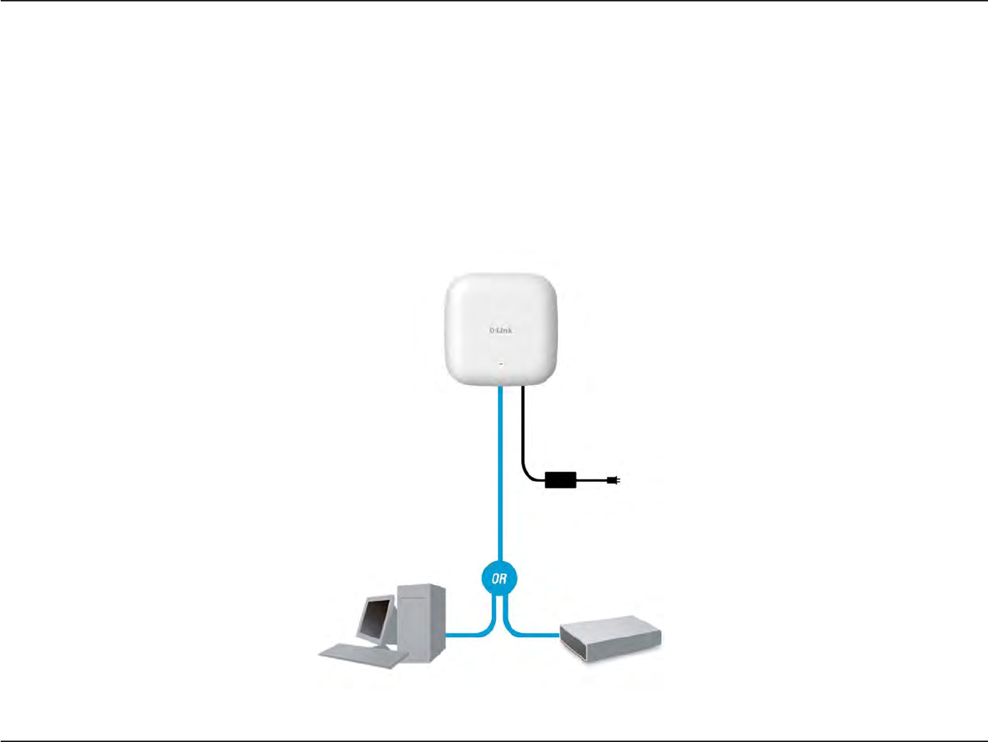
Method
3 -
No
PoE
1.
C
onnec
t
one end
of
your
E
thernet
cable
into
the LAN (PoE)
port
and then
c
onnec
t
the other end
to
a switch,
r
out
er
,
or
c
omput
er
.
2. Use
the supplied power adapt
er
.
C
onnec
t
the power adapter
to
the Power receptor on the
Access
P
oin
t
.
3.
C
onnec
t
the power cable
to
the power adapter and then
c
onnec
t
the other end
into
a power
outlet
.
D
AP
-2330
Power A
dapt
er
PC
S
wit
ch
or
R
out
er
11
D
-
Link
D
A
P
-
2330
U
ser
M
anual
S
e
c
tion
3
-
C
onfigu
r
a
tion
Web User I
n
t
er
fac
e
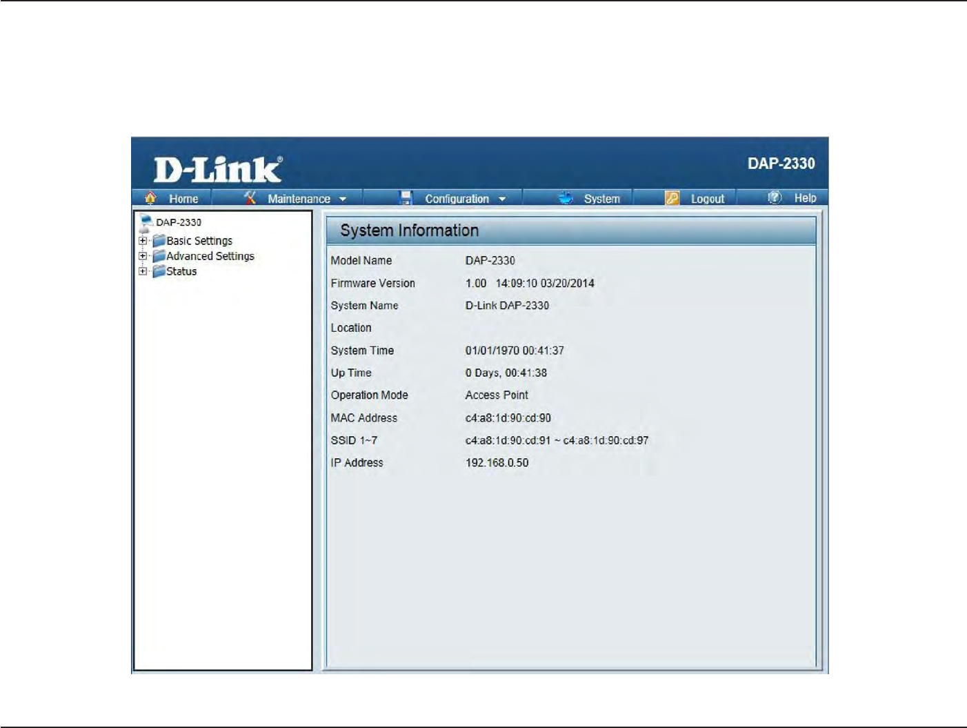
The supports an elabor
a
t
e
web
user
in
t
erfac
e
where
the
user can configure and
monitor the
devic
e
.
Most
of the
configurable settings are
located
in the left
menu
of the web
GUI which contains section called Basic
S
ettings
,
Advanced
S
ettings
and
S
ta
tus
.
12
D
-
Link
D
A
P
-
2330
U
ser
M
anual
S
e
c
tion
3
-
C
onfigu
r
a
tion
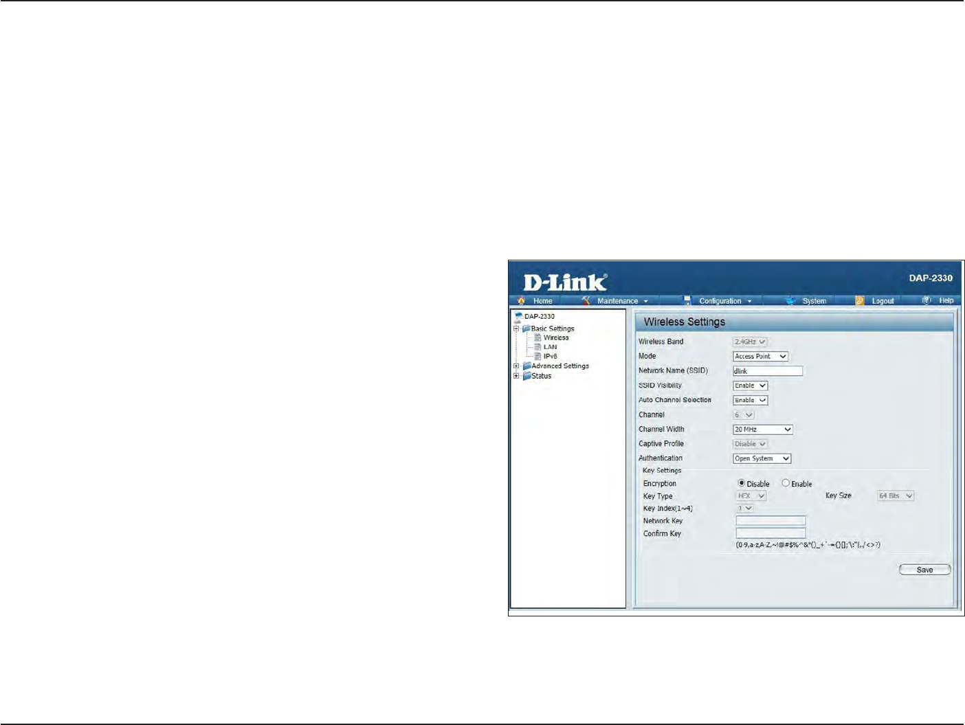
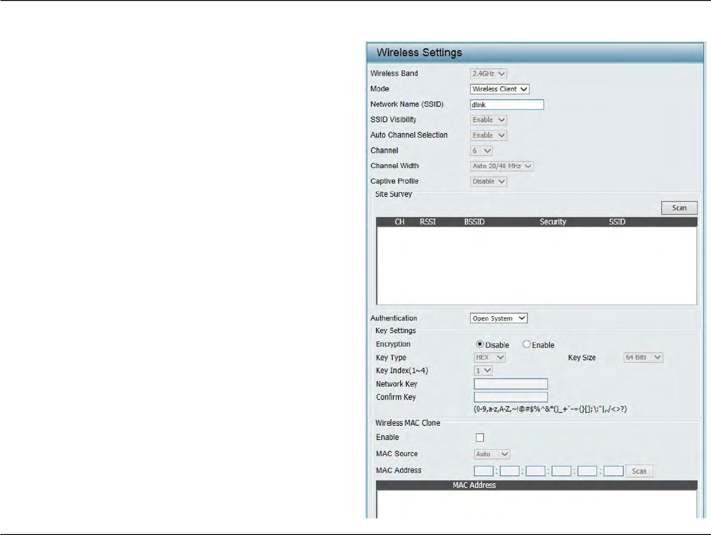
W
ir
eless
On
the
wireless settings page
,
you can setup
the
basic wireless
configuration
for the
access poin
t
.
The user can choose
from 4 different wireless
modes:
Access
P
oin
t
-
Used
to
cr
ea
t
e
a wireless
LAN
WDS
with
AP
-
Used
to
connect
multiple
wireless networks
while still functioning
as a wireless access poin
t
WDS
-
Used
to
connect
multiple
wireless
networks
Wireless
C
lien
t
-
Used when
the
access
point
needs
to
ac
t
as a wireless
network adapter
for
an
E
thernet
enabled
device
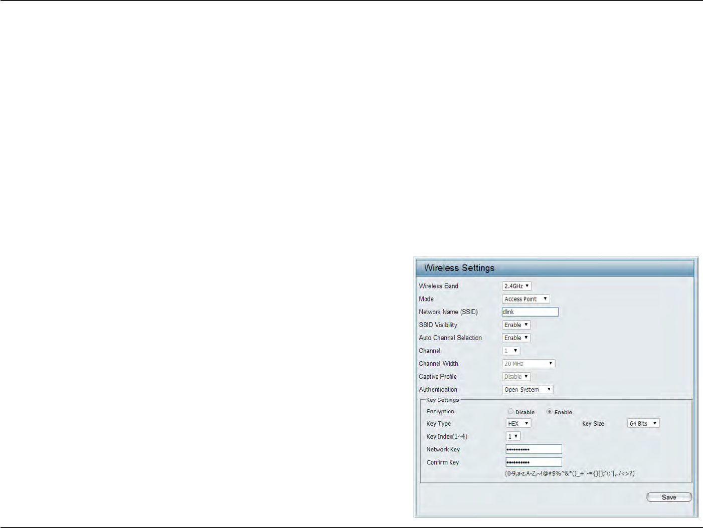
Access
P
oin
t
Mode
Wireless
B
and:
Mode:
Network
Name
(SSID
):
SSID
V
isibilit
y
:
Auto
Channel
S
elec
tion:
S
elec
t
2.4GHz
in
default
.
S
elec
t
Access
Point
from the drop-down
menu
.
S
ervic
e
S
et
Iden
tifier
(SSID
)
is
the
name
designated
for
a specific wireless local area
network
(
WLAN).
T
he
SSID
’
s
fac
t
or
y
default setting
is
dlink
.
T
he
SSID
can
be
easily changed
to
c
onnec
t
to an existing
wireless
network or to
establish
a new
wir
eless
net
w
or
k
.
The SSID can be
up to
32 char
ac
t
ers
and
is case
-sensitiv
e
.
S
elec
t
Enable
to
broadcast
the
SSID across
the
net
w
or
k
,
thus
mak
ing
it
visible
t
o
all
net
w
or
k
users
.
S
elec
t
Disable
to
hide the SSID
from the net
w
or
k
.
This feature
when
enabled automatically
selects
the channel that provides the best
wir
eless
per
f
or
manc
e
.
The channel selection process
only
occurs
when the
AP
is booting up
.
To
manually
selec
t
a
channel
,
set this option to
Disable
and
selec
t
a
channel from the drop-down
menu
.

13
D
-
Link
D
A
P
-
2330
U
ser
M
anual
S
e
c
tion
3
-
C
onfigu
r
a
tion
C
hannel:
Channel W
idth:
Captive
P
r
ofile:
A
uthen
tica
tion:
To change the
channel
,
first
toggle
the
A
ut
o
Channel
S
elec
tion
setting
to
D
isable
,
and then use
the drop-down menu
to make
the desired
selection.
Not
e:
T
he
wireless
adapt
ers
will
aut
omatically
sc
an
and
mat
ch
the
wireless
settings
.
A
llow
s
you
to
selec
t
the
channel
width
you
would
like
to
oper
a
t
e
in.
S
elec
t
20 MHz
if
you are
not
using any 802.11n
wireless
clien
ts
.
Auto 20/40 MHz allows you
to
c
onnec
t
to both
802.11n and 802.11b/g wireless devices on your
net
w
or
k
.
Disable or
selec
t
a Captive Portal profile
for
Primary
SSID
.
Use
the drop-down menu
to
choose
Open
S
y
st
em
,
Shared Key
,
WPA-P
ersonal
,
WPA-En
t
erprise
,
or
802.1x
.
•
S
elec
t
Open System
to
communicate the
key across
the network
(
WEP).
•
S
elec
t
Shared Key
to limit
communication
to only
those devices
that
share
the
same WEP
settings
.
If
multi-SSID
is
enabled
,
this
option
is
not
a
v
ailable
.
•
S
elec
t
WPA-Personal
t
o
secure
y
our
net
w
or
k
using
a
passw
or
d
and
dynamic
key
changes
.
No
R
ADIUS
ser
v
er
is
requir
ed
.
•
S
elec
t
WPA-Enterprise
to
secure your network
with
the inclusion
of
a RADIUS
ser
v
er
.
•
S
elec
t
802.1X
if
your network is
using port-based Network
Access
C
on
tr
ol
.
14
D
-
Link
D
A
P
-
2330
U
ser
M
anual
S
e
c
tion
3
-
C
onfigu
r
a
tion
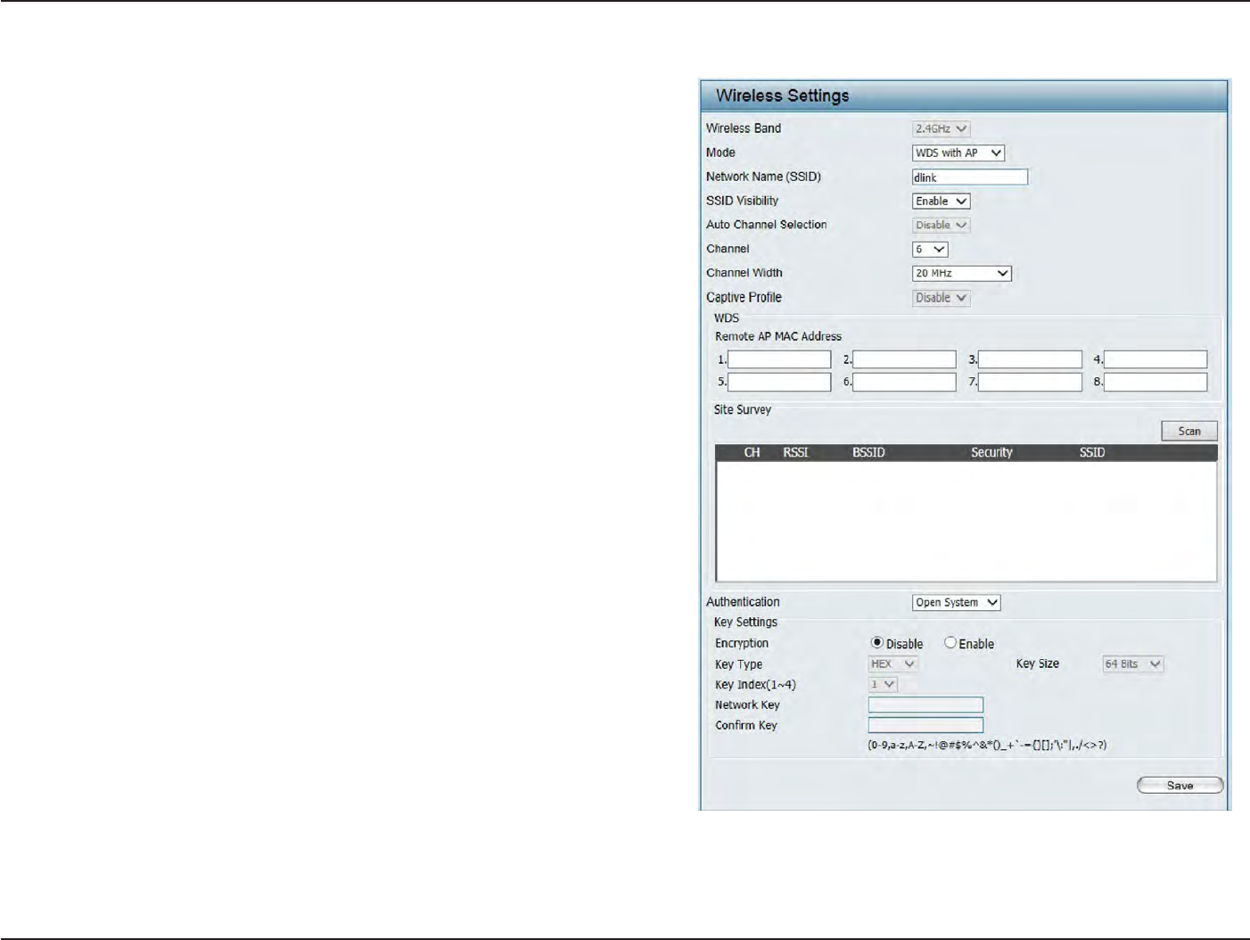
Wireless
Band:
S
elec
t
2.4GHz
in
default
.
WDS
with
AP
Mode
Mode:
Network
Name
(SSID
):
SSID
V
isibilit
y
:
Auto
Channel
S
elec
tion:
C
hannel:
Channel W
idth:
WDS
with
AP
mode
is
selec
t
ed
fr
om
the
drop-down
menu
.
S
ervic
e
S
et
Iden
tifier
(SSID
)
is
the
name
designated
for a
specific wireless local area
network
(
WLAN).
The SSID’s
factory default setting
is dlink
.
The
SSID
can
be
easily changed
to
c
onnec
t
to an existing
wireless
network or to
establish
a new
wir
eless
net
w
or
k
.
Enable
or
Disable SSID visibilit
y
.
Enabling
this
feature broadcasts
the
SSID across
the
net
w
or
k
,
thus making
it
visible
to
all network
users.
Enabling this feature automatically
selec
ts
the
channel
that will provide the best
wir
eless
per
f
or
manc
e
.
T
his
f
ea
tur
e
is
not
suppor
t
ed
in
WDS
with
AP
mode
.
The channel selection process
only
occurs when the AP is
booting up
.
All
devices
on the network must
share
the
sa
me
c
h
a
nn
e
l
.
T
o
c
h
a
n
g
e
t
h
e
c
h
a
nn
e
l
,
use
t
h
e
drop-down
menu to
make
the
desired selection. (Note:
T
he
wir
eless
adapt
ers
will
aut
oma
tically
scan
and
match
the wireless settings
.)
A
llow
s
you
to
selec
t
the
channel
width
you
w
ould
like
t
o
oper
a
t
e
in.
S
elec
t
20
MH
z
if
y
ou
ar
e
not
using
any
802.11n
wir
eless
clien
ts
.
A
ut
o
20/40
MH
z
allo
w
s
you to
connect
to both
802.11n
and 802.11b/g
wireless devices on your
net
w
or
k
.

15
D
-
Link
D
A
P
-
2330
U
ser
M
anual
S
e
c
tion
3
-
C
onfigu
r
a
tion
Captive
P
r
ofile:
R
emot
e
AP MAC
A
ddr
ess:
Site Sur
v
e
y
:
A
uthen
tica
tion:
Disable or
selec
t
a Captive Portal pr
ofile
.
En
t
er
the MAC addresses
of
the APs
on your network
that will
serve as
bridges
to
wirelessly
c
onnec
t
multiple
net
w
or
ks
.
Click on the
Scan
button to
search
for
available wireless
net
w
or
ks
,
then click on the available network
that
you want
t
o
c
onnec
t
with.
Use
the drop-down menu
to
choose
Open
S
y
st
em
,
Shared Key
, or
WPA-P
ersonal
.
•
S
elec
t
Open
S
yst
em
to
communicate the
key across the
net
w
or
k
.
•
S
elec
t
Shar
ed
Key
to limit
communication
to
only
those
devic
es
that
share
the
same
WEP
settings
.
I
f
multi-SSID is
enabled
,
this
option
is
not
a
v
ailable
.
•
S
elec
t
WPA-Personal
to
secure your network using a password and dynamic key
changes
.
No RADIUS server is
requir
ed
.
16
D
-
Link
D
A
P
-
2330
U
ser
M
anual
S
e
c
tion
3
-
C
onfigu
r
a
tion
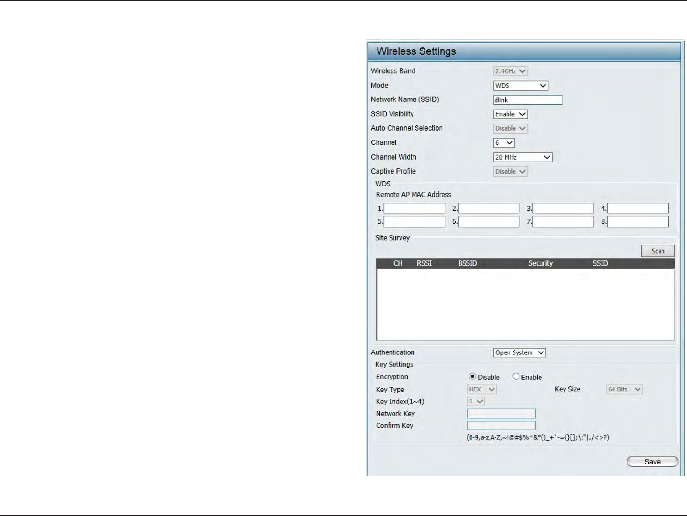
Wireless
Band:
S
elec
t
2.4GHz
in
default
.
WDS
Mode
Mode:
Network
Name
(SSID
):
SSID
V
isibilit
y
:
Auto
Channel
S
elec
tion:
C
hannel:
Channel W
idth:
Captive
P
r
ofile:
R
emot
e
AP MAC
A
ddr
ess:
WDS is
selec
t
ed
from the drop-down menu
.
S
ervic
e
S
et
Identifier
(SSID
)
is
the
name
designated
f
or
a
specific
wir
eless
local
ar
ea
net
w
or
k
(
WLAN).
T
he
SSID’s
factory default setting
is
dlink
.
The SSID
can
be
easily
changed
t
o
c
onnec
t
t
o
an
e
xisting
wireless
network or
to
establish a new wireless
net
w
or
k
.
Enable
or
Disable SSID visibilit
y
.
Enabling
this
f
ea
tur
e
br
oadcasts
the
SSID
acr
oss
the
net
w
or
k
,
thus
making
it
visible
to
all network
users.
Enabling this feature automatically
selec
ts
the
channel
that will provide the best wireless
per
f
or
manc
e
.
This feature is
not
supported
in
WDS
mode
.
All
devices
on the network must
share
the same
c
h
a
nn
e
l
.
T
o
c
h
a
n
g
e
t
h
e
c
h
a
nn
e
l
,
u
s
e
t
h
e
drop-down
menu
to
make the desired
selection.
Use
the drop-down menu to
choose
20
MHz
or
Auto 20/40 MH
z.
Disable
in
default
.
En
t
er
the
M
A
C
addr
esses
of
the
AP
s
on
y
our
network
that will
serve as
bridges to
wirelessly
connect
multiple
net
w
or
ks
.

17
D
-
Link
D
A
P
-
2330
U
ser
M
anual
S
e
c
tion
3
-
C
onfigu
r
a
tion
Site Sur
v
e
y
:
A
uthen
tica
tion:
Click
on the
Scan
button to
search
for
available wireless
net
w
or
ks
,
then
click
on the
available network
that you
want to
connect
with.
Use
the drop-down
menu
to
choose
Open
S
y
st
em
,
Shared Key
,
or
WPA-P
ersonal
.
•
S
elec
t
Open
S
yst
em
to
communicate
the
key across
the
net
w
or
k
.
•
S
elec
t
Shared Key
to limit
communication
to only
those devices
that
share
the
same WEP
settings
.
•
S
elec
t
WPA-Personal
to
secure your network using a password and dynamic key changes
.
No RADIUS server
is
requir
ed
.
18
D
-
Link
D
A
P
-
2330
U
ser
M
anual
S
e
c
tion
3
-
C
onfigu
r
a
tion
Wireless
Band:
S
elec
t
2.4GHz
in
default
.
Wireless
C
lien
t
Mode
Mode:
Network
Name
(SSID
):
SSID
V
isibilit
y
:
Auto
Channel
S
elec
tion:
C
hannel:
Channel W
idth:
Site Sur
v
e
y
:
Captive
P
r
ofile:
A
uthen
tica
tion:
W
ir
eless
Clien
t
is
selec
t
ed
fr
om
the
drop
-
do
wn
menu
.
S
ervic
e
Set
Identifier
(SSID) is
the
name
designated
f
or
a
specific
wir
eless
local
ar
ea
net
w
or
k
(
WLAN).
T
he
SSID’s
factory
default setting is dlink
.
The SSID
can
be easily changed
to
c
onnec
t
to
an
existing
wireless
net
w
or
k
.
This
option
is
unavailable
in
Wireless
Clien
t
mode
.
Enabling
this
f
ea
tur
e
aut
oma
tically
selec
ts
the
channel
that will
provide the
best wireless
per
f
or
manc
e
.
T
his
feature is
not
supported
in
Wireless
Clien
t
mode
.
T
he
channel
used
will
be
displayed
,
and
ma
t
ches
the
AP
that the
DAP-2330 is c
onnec
t
ed
to when
set
t
o
Wireless
Clien
t
mode
.
U
se
the
drop
-
do
wn
menu
to
choose
20
MH
z
or
Auto
20/40 MH
z.
Click
on the
Scan
button to
search
for available
wir
eless
net
w
or
ks
,
then
click
on
the
a
v
ailable
network
that
you want
to
c
onnec
t
with.
Disable
in
default
.
Will be explained
in
the next
t
opic
.
19
D
-
Link
D
A
P
-
2330
U
ser
M
anual
S
e
c
tion
3
-
C
onfigu
r
a
tion
Wireless
S
ecurit
y
Wireless
security
is a key concern
for
any wireless network
installed
.
Unlike any
other
networking method
wireless networks
will
broadcast it’s presence
for
any
one
to
c
onnec
t
to
it
.
T
oday
,
wireless
security
has
advanced
to
a
level
wher
e
it
is
virtually impenetr
able
.
There are mainly
two
forms
of
wireless encryption and they are called Wired
E
quiv
alen
t
Privacy (WEP)
and Wi-Fi
P
r
ot
ec
t
ed
Access (WPA). WEP was
the first
secur
it
y
method
dev
eloped
.
I
t
is
a
lo
w
level
encryption
but
bett
er
than
no
w
encr
yption.
W
P
A
is
the
new
est
encryption
standar
d
and
with
the
advanced
W
P
A2
standard wireless networks
ha
v
e
finally r
each
a
point
wher
e
the
security
is
strong enough
to g
iv
e
users
the
peac
e
of mind
when installing wireless
net
w
or
ks
.
Wired
E
quiv
alen
t
Privacy
(
WEP
)
WEP
pr
o
vides
two
variations called
O
pen
S
y
stem
and
S
hared
K
e
y
.
O
pen
S
y
stem
will
send
a
r
equest
t
o
the
acc
ess
point
and
if
the
key
used
ma
t
ches
the
one
c
onfigur
ed
on
the
acc
ess
poin
t
,
the
acc
ess
point
will
return
a
succ
ess
message
back
to
the
wir
eless
clien
t
.
I
f
the
key
does
not
ma
t
ch
the
one
c
onfigur
ed
on
the
acc
ess
poin
t
,
the
acc
ess
point will
den
y
the
connection r
equest
from
the
wireless
clien
t
.
S
hared
K
e
y will
send
a
r
equest
to
the
acc
ess
point
and
if
the
key
used
ma
t
ches
the
one
c
onfigur
ed
on
the
acc
ess
poin
t
,
the
acc
ess
point will
send
a
challenge
to
the
clien
t
.
T
he
clien
t
will
then
again
send
a
c
onfir
ma
tion
of
the
same
key
back
to
the
access
point
wher
e
the
access
point will
either return
a
successful
or
a
denial packet back
to
the
wireless
clien
t
.
Encr
yption:
Key
T
ype*:
Key
Size:
Key
Index
(1-4):
Ke
y
:
Use
the
radio
button to
disable
or enable
encryption.
S
elec
t
HEX
or
ASCII.
S
elec
t
64 Bits
or
128
Bits
.
S
elec
t
the
1st
through the 4th
key
to be the active
key
.
Input up to four
keys
for
encryption. You
will select
one
of
these keys
in the
Key Index
drop-down
menu
.
**Hexadecimal
(HEX)
digits
consist
of the
numbers 0-9 and
the
letters
A
-F
.
*ASCII (American
S
tandar
d
Code
for
Information
I
n
t
erchange)
is a code
that
represents English letters
using
numbers ranging
from 0-127.
20
D
-
Link
D
A
P
-
2330
U
ser
M
anual
S
e
c
tion
3
-
C
onfigu
r
a
tion
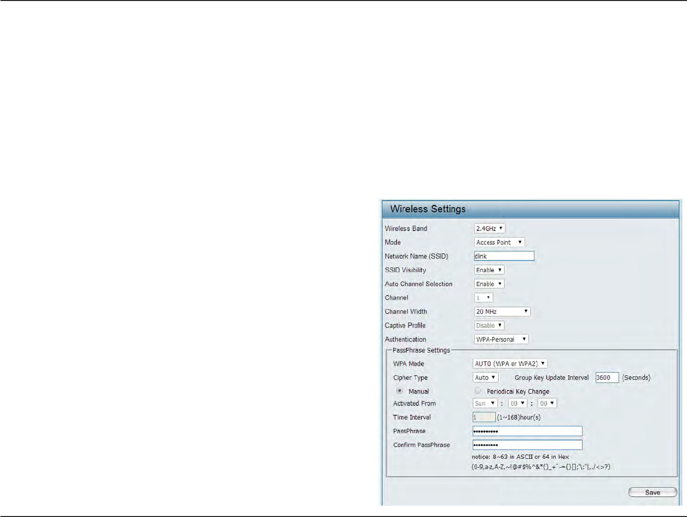
Wi-Fi
P
r
ot
ec
t
ed
Access (WPA
/
WP
A2)
WPA was
cr
ea
t
ed
by
the Wi-Fi Alliance
to
address
the
limitations and
weaknesses
found in
WEP. This
protocol
is mainly based
on the 802.11i
standar
d
.
There are also
two
variations
found in
WPA called WPA-Personal
(PSK) and
W
P
A
-En
t
er
pr
ise
(EAP).
WPA-EAP requires
the
user
to
install a Radius
S
er
v
er
on the
network
for authentication.
WPA-Personal does
not
require
the
user
to
install a Radius
S
er
v
er
on the
net
w
or
k
.
Comparing
WPA-PSK
with
WPA-EAP, WPA-PSK is seen as a
weaker authentication
but
comparing
WPA-PSK
to
WEP, WPA-PSK is
far more
secure
than
WEP. WPA-EAP is
the
highest level
of
wireless security a user can use
for
wireless
t
oday
.
WPA2 is an upgrade
of
WPA. WPA2
yet
again solves some possible security
issues
found in
WPA. WPA2 has
two
variations called
W
P
A2-P
ersonal
(PSK) and
W
P
A2-En
t
er
pr
ise
(EAP)
which is
the
same as
found with
W
P
A.
WPA
Mode:
Cipher
T
ype:
Group Key
Upda
t
e:
Pass P
hr
ase:
When WPA-Personal is selec
t
ed
for
Authentication
t
ype
,
you must
also selec
t
a WPA
mode from the drop-down
m
en
u
:
AUTO (WPA
or
WPA2), WPA2
On
l
y
,
or
WPA
O
nly
.
WPA and WPA2 use
different
algorithms
.
AUTO (WPA
or
WPA2) allows you
to
use
both
WPA
and
W
P
A2.
W
hen
y
ou
selec
t
W
P
A
-P
ersonal
,
y
ou
must
also
selec
t
A
UT
O
,
AES,
or
TKIP
from the
pull down
menu
.
S
elec
t
the
in
t
er
v
al
dur
ing
which
the
g
r
oup
key
will
be
valid
.
The default value
of
1800 is
r
ec
ommended
.
W
hen
y
ou
selec
t
W
P
A
-P
ersonal
,
please
en
t
er
a
Pass
P
hr
ase
in
the corresponding field
.
21
D
-
Link
D
A
P
-
2330
U
ser
M
anual
S
e
c
tion
3
-
C
onfigu
r
a
tion
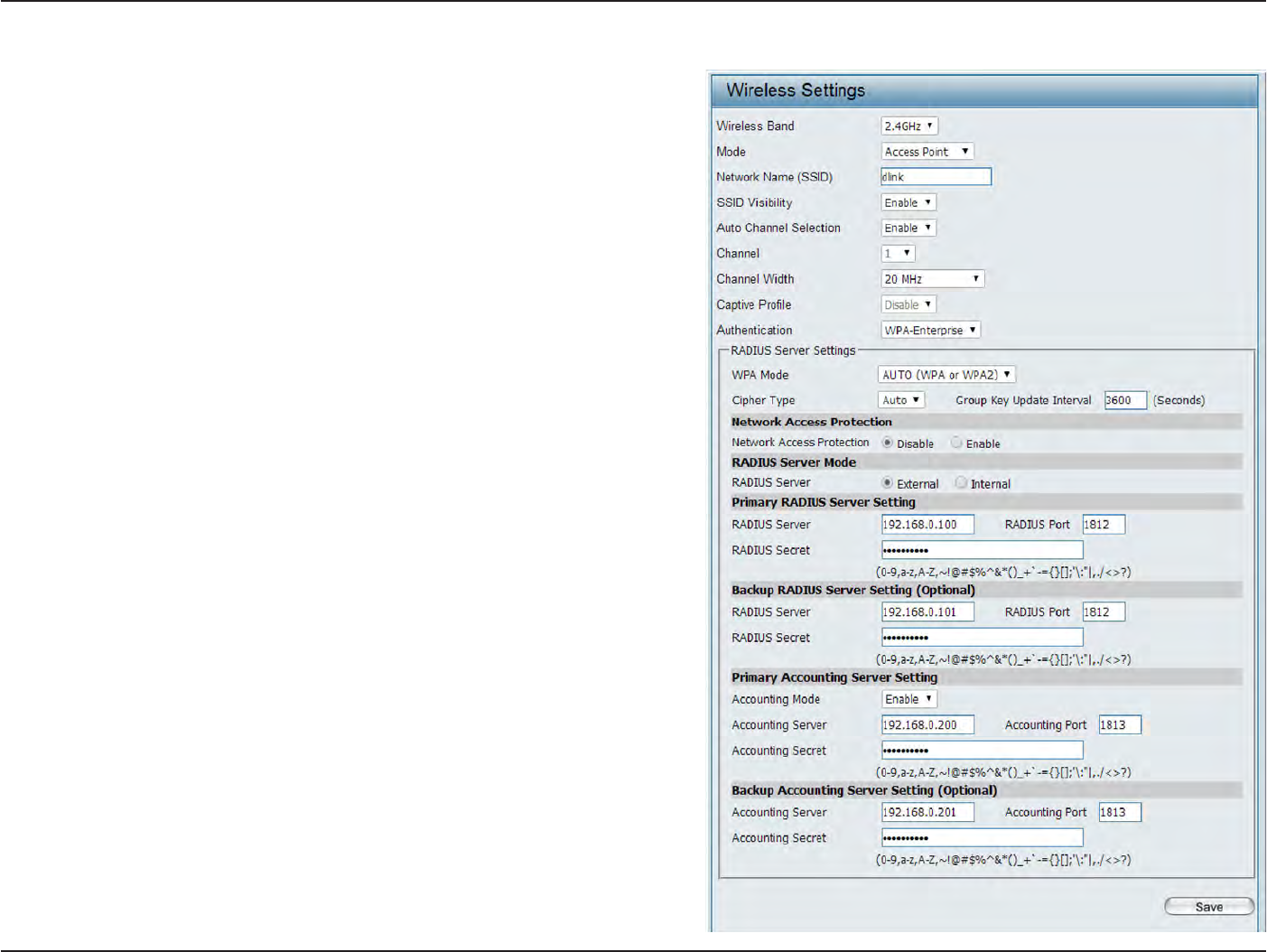
WPA
Mode:
Cipher
Type:
Group Key
Upda
t
e
I
n
t
er
v
al:
Network
Access
P
rot
ec
tion:
RADIUS
S
er
v
er:
RADIUS
P
or
t:
RADIUS
S
ecr
et:
A
cc
oun
t
S
er
v
er:
A
cc
oun
t
P
or
t:
A
cc
oun
t
S
ecr
et:
When
W
P
A
-En
t
er
pr
ise
is selec
t
ed
,
you must
also
selec
t
a WPA
mode from the drop-down menu:
AUTO (WPA
or
WPA2), WPA2
Only
,
or
WPA
Only
.
WPA
and
WPA2 use
different
algorithms
.
A
UT
O
(WPA
or
WPA2) allows
you to
use
both
WPA
and
WPA2.
When
W
P
A
-En
t
er
pr
ise
is selec
t
ed
,
you must
also
selec
t
a cipher
type from the drop-down menu:
A
ut
o
,
AES, or
TKI
P
.
S
elec
t
the interval during which the group key
will be
valid
.
1800 is
the
recommended value as
a
lower interval
may reduce data transfer
r
a
t
es
.
Enable
or disable Microsoft Network
A
cc
ess
P
r
ot
ec
tion.
En
t
er
the
IP address
of the
RADIUS
ser
v
er
.
En
t
er
the
RADIUS por
t
.
En
t
er
the
RADIUS
secr
et
.
En
t
er
the
IP address
of the
Account
S
er
v
er
En
t
er
the
Account por
t
En
t
er
the
Account
secr
et
22
D
-
Link
D
A
P
-
2330
U
ser
M
anual
S
e
c
tion
3
-
C
onfigu
r
a
tion
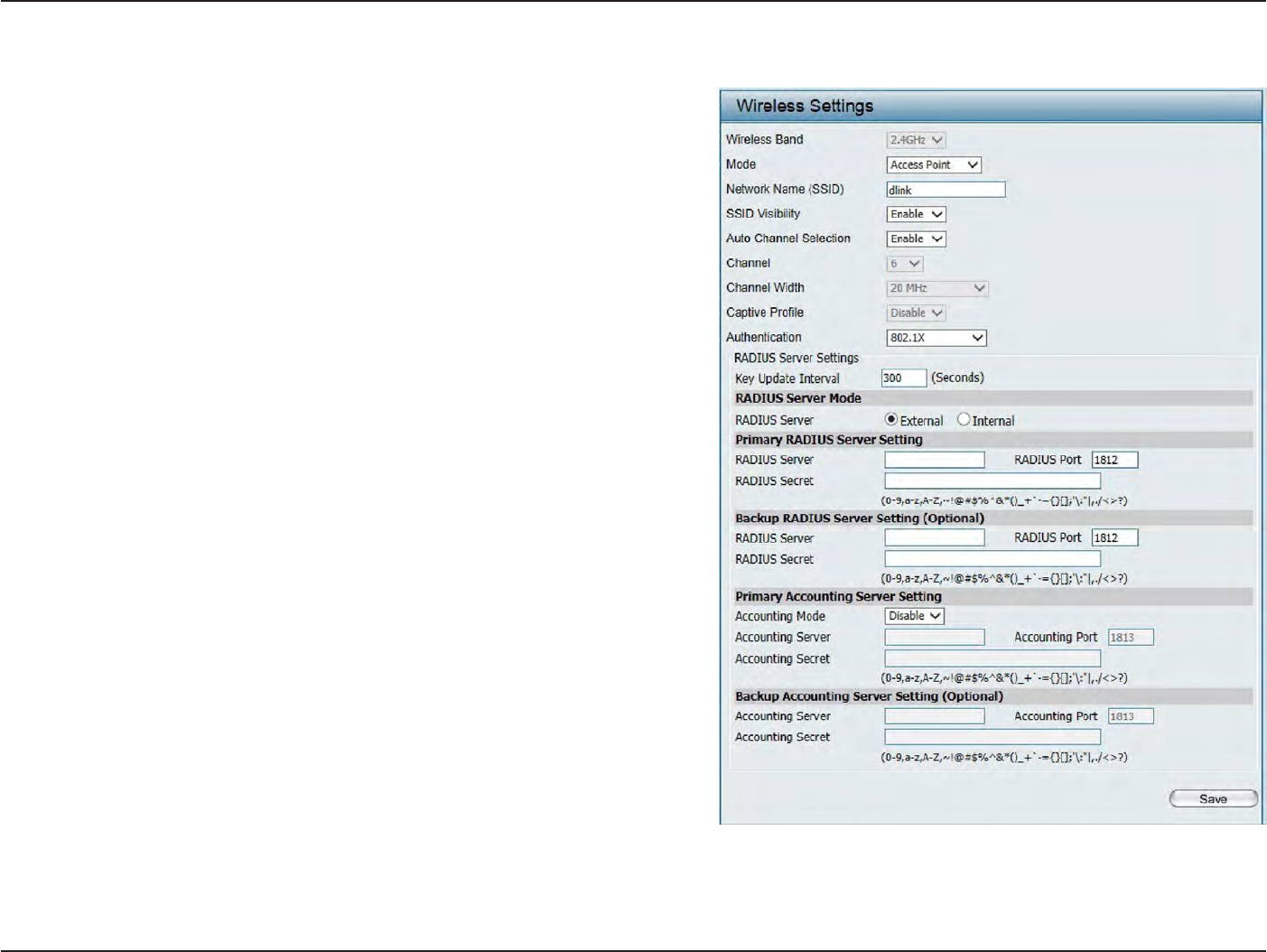
802.1x A
uthen
tica
tion
Key
Upda
t
e
Interval
:
RADIUS
S
er
v
er
Mode
:
RADIUS
S
er
v
er:
RADIUS
P
or
t
:
RADIUS
S
ecr
et:
A
cc
oun
t
S
er
v
er:
A
cc
oun
t
P
or
t:
A
cc
oun
t
S
ecr
et:
S
elec
t
the
in
t
er
v
al
dur
ing
which
the
g
r
oup
key
will
be
valid
(300
is the
recommended value).
A lower interval may
reduce data transfer
r
a
t
es
.
S
elec
t
Ex
t
ernal
or Internal
RADIUS
server
En
t
er
the IP address
of
the RADIUS
ser
v
er
.
En
t
er
the RADIUS por
t
.
En
t
er
the RADIUS
secr
et
.
En
t
er
the IP address
of
the Account
S
er
v
er
En
t
er
the Account por
t
En
t
er
the Account
secr
et
23
D
-
Link
D
A
P
-
2330
U
ser
M
anual
S
e
c
tion
3
-
C
onfigu
r
a
tion
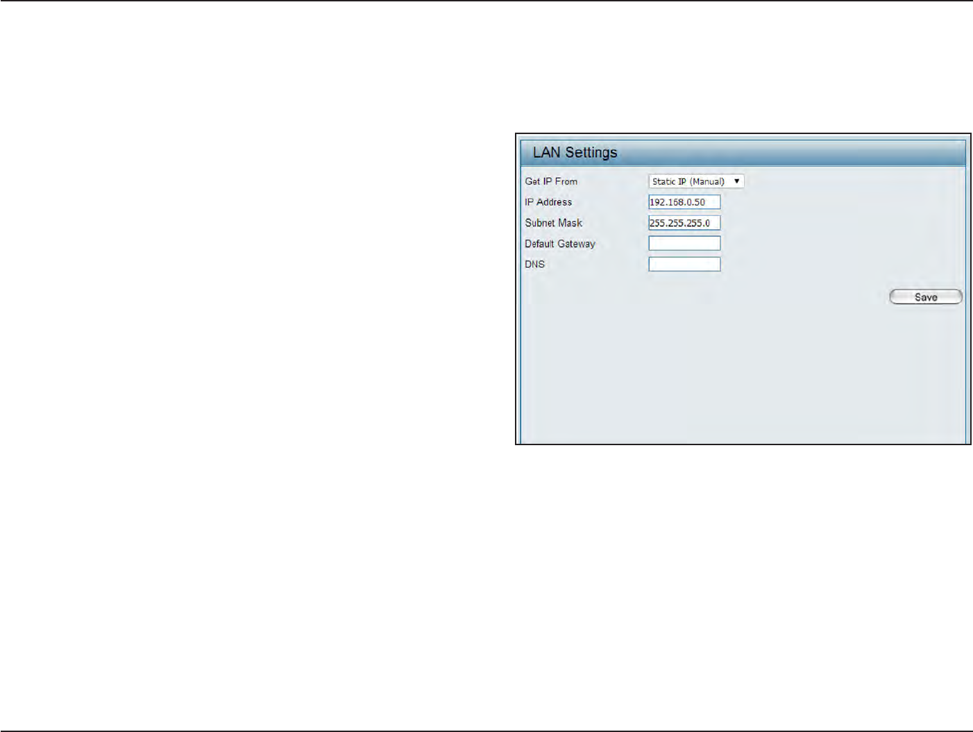
L
AN
LAN is
short
for
Local Area
Net
w
or
k
.
This is considered
your internal net
w
or
k
.
These are
the
IP
settings
of the
LAN
in
t
erfac
e
for the DAP-2330.
These settings may
be
referred
to
as
private
settings
.
You may change
the
LAN IP address
if
needed
.
The LAN IP address is
private
to
your
internal
network and cannot
be
seen
on the
I
n
t
er
net
.
Get IP
F
r
om:
IP
A
ddr
ess:
Subnet M
ask
:
Default
G
a
t
e
w
a
y
:
DNS:
S
ta
tic
IP (Manual) is chosen
her
e
.
Choose this
option
if
y
ou
do not
ha
v
e
a
DHCP
ser
v
er
in
y
our
net
w
or
k
,
or
if
you
wish
to
assig
n
a
sta
tic
IP
address
to
the
D
AP
-2330.
When
D
ynamic
IP
(DHCP) is
selec
t
ed
,
the
other
fields
her
e
will
be
g
r
a
yed
out
.
P
lease
allo
w
about
2
minut
es
f
or
the
DHCP
client
to
be functional once this selection
is
made
.
The
default
IP address
is
192.168.0.50. Assign
a static
IP address
that is within the
IP address range
of your
net
w
or
k
.
En
t
er
the
subnet mask. All devices
in the
network
must
share the same subnet
mask
.
En
t
er
the
IP address
of the
gateway/router
in your
net
w
or
k
.
En
t
er
a DNS server IP address. This is usually
the
local
IP
address
of
your
ga
t
ew
a
y/rout
er
.
24
D
-
Link
D
A
P
-
2330
U
ser
M
anual
S
e
c
tion
3
-
C
onfigu
r
a
tion
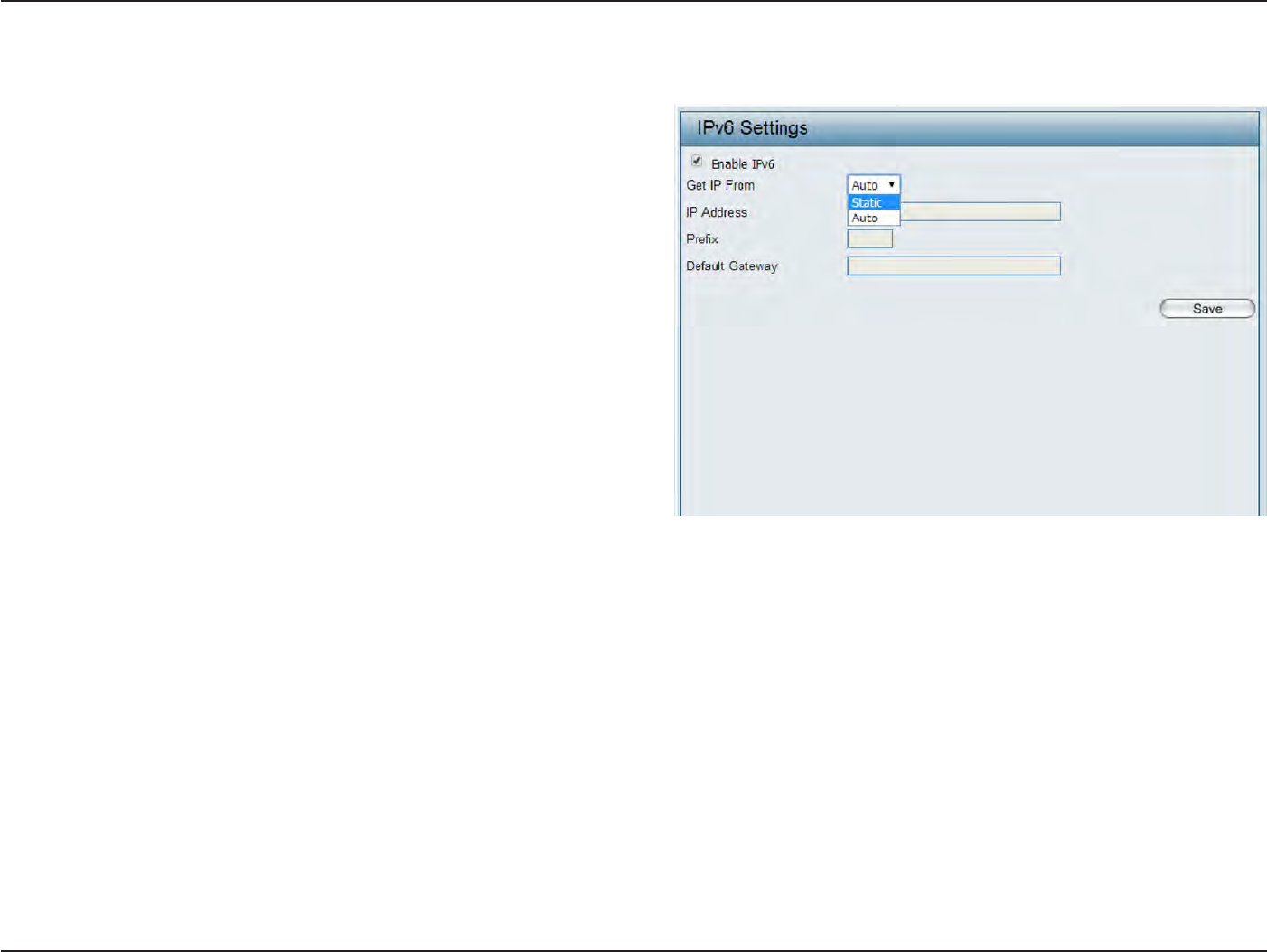
IP
v6
Enable
IP
v6:
Get IP
F
r
om:
IP
A
ddr
ess:
P
r
efix:
Default
G
a
t
e
w
a
y
:
Check
to
enable the
IP
v6
Auto is chosen
her
e
.
Choose
this option the
DAP-2330
can get
IPv6 address
automatically
or use
S
ta
tic
to
set IPv6 address
manually
.
W
hen
A
ut
o
is
selec
t
ed
,
the
other
fields
her
e
will
be
grayed
out
.
En
t
er
the LAN IPv6 address used
her
e
.
En
t
er
the
LAN
subnet prefix length
value used her
e
.
En
t
er
the LAN default
ga
t
ew
a
y
IPv6 address used
her
e
.
25
D
-
Link
D
A
P
-
2330
U
ser
M
anual
S
e
c
tion
3
-
C
onfigu
r
a
tion
Advanced
S
ettings
I
n
the Advanced
S
ettings
S
ec
tion
the user can configure advanced settings concerning
P
er
f
or
manc
e
,
Multiple
SSID
,
VLAN,
S
ecur
it
y
,
Quality of
Service,
AP
A
rr
a
y
,
W
eb
R
edir
ec
tion,
DHCP
S
er
v
er
,
F
ilt
ers
and
S
cheduling
.
T
he
f
ollo
wing
pages
will
e
xplain
settings
f
ound
in
the
A
dv
anced
S
ettings
sec
tion
in
mor
e
detail
.
26
D
-
Link
D
A
P
-
2330
U
ser
M
anual
S
e
c
tion
3
-
C
onfigu
r
a
tion
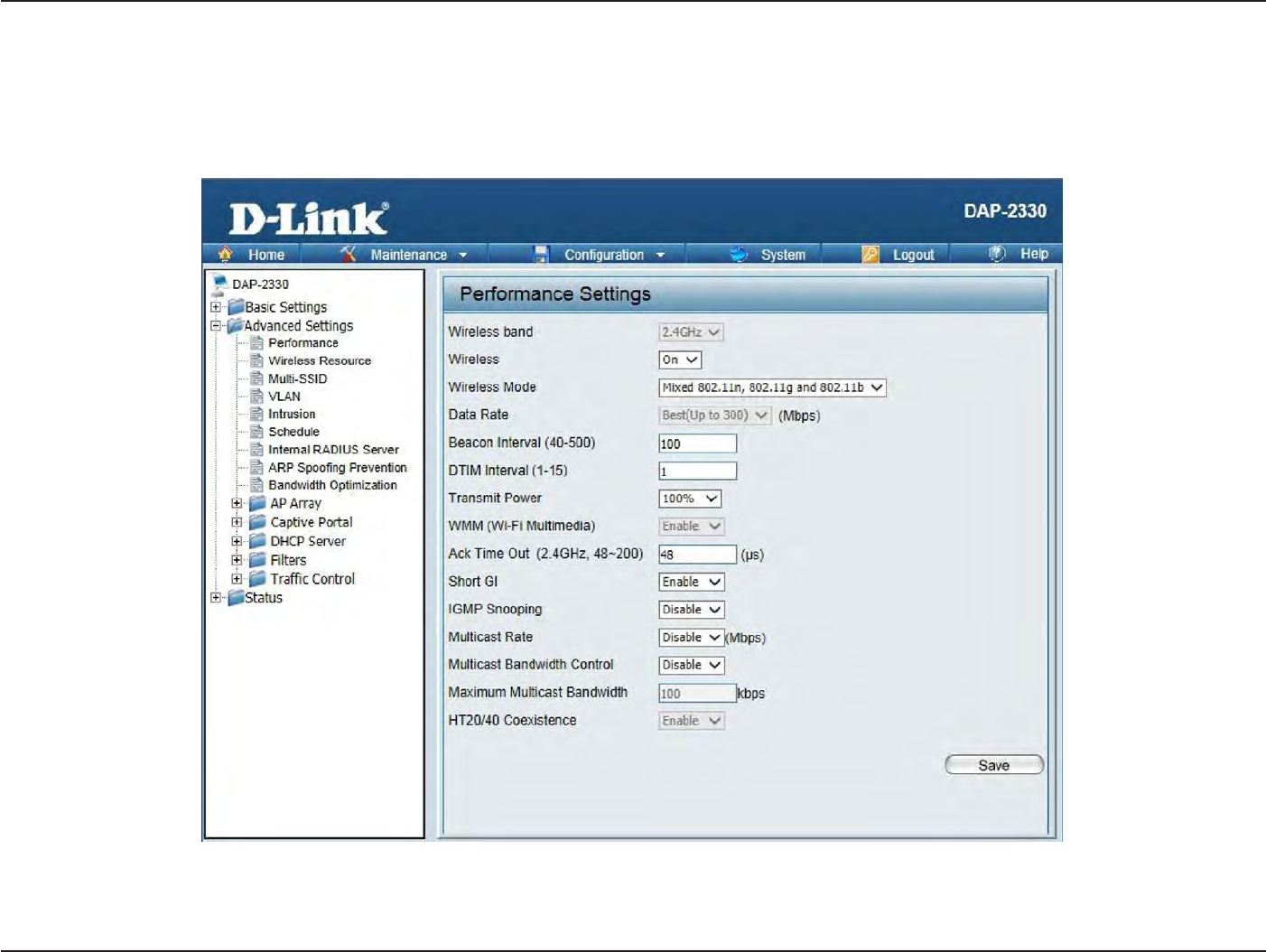
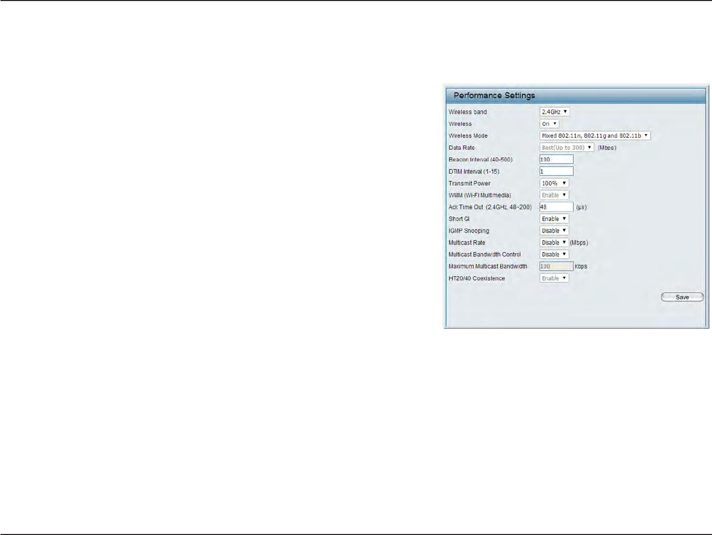
P
er
f
ormanc
e
On
the
Performance
S
ettings
page
the
users can
configure more advanced settings concerning
the
wireless signal and
hosting
.
Wireless
B
and:
W
ir
eless:
Wireless
Mode:
Data
R
a
t
e*:
Beacon
Interval
(25-500):
DTM
Interval
(1-15):
S
elec
t
2.4Ghz
in
default
.
Use
the drop-down menu
to turn
the wireless function On or
O
ff
.
The
different combination
of
clients
that
can
be supported
include
Mix
ed
802.11n,
802.11g
and
802.11b
,
Mix
ed
802.11g
and
802.11b
and
802.11n Only
in
the
2.4
GHz
band
P
lease
not
e
that
when
backwards
compatibility
is enabled
for
legacy (802.11g/b)
clien
ts
,
degradation
of
802.11n wireless performance
is
e
xpec
t
ed
.
I
ndica
t
e
the
base transfer
r
a
t
e
of
wireless adapters
on the wireless
LAN.
T
he
AP
will
adjust
the
base
tr
ansfer
r
a
t
e
depending on
the
base
r
a
t
e
of
the
c
onnec
t
ed
devic
e
.
I
f
ther
e
ar
e
obstacles
or
in
t
er
f
erenc
e
,
the
AP
will
step
down the
r
a
t
e
.
This
option
is enabled
in
Mixed
802.11g
and 802.11b mode (for
2.4 GHz).
The choices available are Best
(Up
to
54), 54, 48, 36, 24, 18, 12, 9, 6, 11, 5.5, 2 or 1
for
2.4
GH
z.
Beacons
are
packets
s
en
t
by an
access
point to
synchronize
a
wireless
net
w
or
k
.
Specify a value
in
milliseconds
.
The default
(100)
is
r
ec
ommended
.
S
etting
a higher beacon
interval
can help
to
sa
v
e
the power of
wireless
clien
ts
,
while setting
a
lower one
can
help a
wireless
client
c
onnec
t
to
an access
point
faster
.
S
elec
t
a Delivery Traffic Indication
Message setting between 1 and 15. 1 is
the
default setting
.
DTIM is a
countdown
inf
or
ming
clients
of
the next
window for
listening
to
broadcast and multicast
messages
.

27
D
-
Link
D
A
P
-
2330
U
ser
M
anual
S
e
c
tion
3
-
C
onfigu
r
a
tion
Transmit
P
ow
er:
WMM (Wi-Fi
Multimedia):
Ack Time
O
ut
(2.4 GHZ,
64~200):
S
hor
t
GI:
IGMP
Snooping:
Multicast
B
andwidth
C
on
tr
ol
:
HT20/40 Coexistence
:
T
his
setting
det
ermines
the
po
w
er
level
of
the
wir
eless
tr
ansmission.
T
ransmitting
po
w
er
can
be
adjust
ed
t
o
elimina
t
e
overlapping
of
wireless area coverage between
two
access points where
in
t
er
f
erenc
e
is a major concern. For
e
xample
,
if
wireless coverage
is
intended
for
half
of
the area, then selec
t
50% as
the option.
Use
the drop-down menu
to
selec
t
100%, 50%, 25%, or
12.5%.
WMM stands
f
or
Wi-Fi
Multimedia. Enabling this feature
will
improve the user experience
for
audio and video applications
over
a
Wi-Fi
net
w
or
k
.
To effectively optimize
throughput
over
long
distance links
enter
a value
for
Acknowledgement
Time
Out
between 64
to 200
microseconds
in
the 2.4 GHz
in
the field provided
.
S
elec
t
Enable
or
Disable
.
Enabling a
short guard interval
can increase
throughput
.
Ho
w
ever
,
be aware
that it
can also
increase
the error r
a
t
e
in
some installations due
to
increased sensitivity
to
radio-frequency installa
tions
.
S
elec
t
Enable
or
Disable
.
I
n
t
er
net
Gr
oup
M
anagemen
t
P
r
ot
oc
ol
allo
w
s
the
AP
t
o
r
ec
og
niz
e
IGMP
quer
ies
and
repor
ts
sen
t
between
r
out
ers
and an
IGMP host (wireless
ST
A
).
W
hen
IGMP
snooping
is
enabled
,
the AP
will
forward multicast packets
to
an
IGMP
host
based on IGMP messages passing
through
the AP.
Adjust the multicast packet data
r
a
t
e
her
e
.
The multicast
r
a
t
e
is
supported
in
AP
mode
,
and
WDS
with
AP
mode
,
including M
ulti-SSIDs
Enable this
option to
reduce
in
t
er
f
erenc
e
from
other wireless networks
in
your area. If the channel
width
is
operating at
40MHz
and
ther
e
is
another
wir
eless
net
w
or
k’
s
channel
ov
er
-lapping
and
causing
in
t
er
f
erenc
e
,
the
A
cc
ess
P
oin
t
will
aut
oma
tically
change
to 20MHz
28
D
-
Link
D
A
P
-
2330
U
ser
M
anual
S
e
c
tion
3
-
C
onfigu
r
a
tion
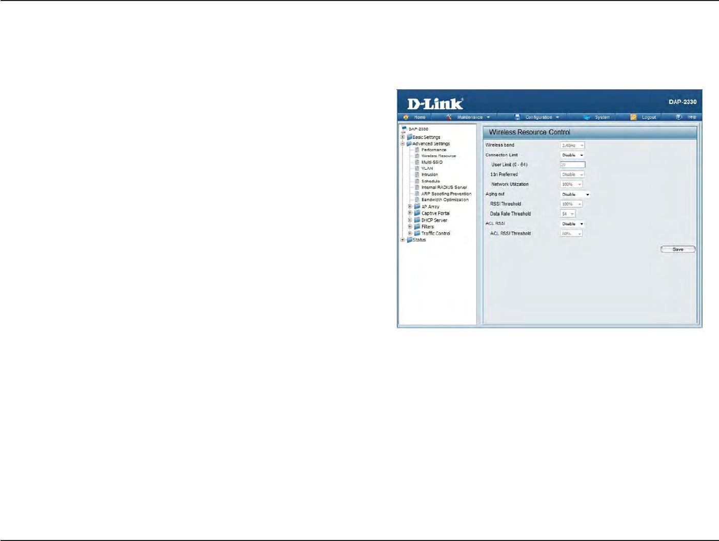
Wireless Resource
C
on
tr
ol
The Wireless Resource Control
window
is used
to
configure
the
wireless connection settings so
that the
device can
detect
the better wireless
connection
in
your
en
vironmen
t
.
Wireless
band:
C
onnec
tion
Limit:
User
Limit:
11n
P
r
eferr
ed:
Network Utiliza
tion:
Aging
out:
S
elec
t
2.4GHz
in
default
.
S
elec
t
Enable
or
D
isable
.
This is an
option for load
balancing
.
This determines whether
to limit the num-
ber
of
users accessing this
devic
e
.
The exac
t
number
is
entered
in the
User
Limit field
belo
w
.
This
feature
allows
the
user
to
share
the
wireless network
traffic
and
the client
using
multiple
APs.
If
this
function is
enabled and when
the
number
of
users exceeds
this
v
alue
,
or the
network
utilization of
this AP
exceeds
the
percentage
that
has been
specified
,
the DAP-
2330
will not
allow clients
to
associa
t
e
with the
A
P
.
Set
the
maximum
amount of
users
that
are
allowed
access (zero
to
64 users)
to the
device using
the
specified wireless
band
.
The default setting is
20.
Use
the drop-down
menu
to
Enable
the
11n
P
r
e
-
ferred function. The wireless clients
with 802.11n
protocol will
have higher
priority to
connect
to the
devic
e
.
Set
the
maximum
utilization of
this access
point for
ser
vic
e
.
The DAP-2330
will not
allow any new clients
to associate
with the
AP
if the utilization
exceeds
the
value
the
user specifies
.
S
elec
t
a
utilization
percentage between 100%,
80%,
60%, 40%, 20%,
or
0%.
When this network
utilization
threshold is
r
eached
,
the
device
will
pause one
minute to
allow
net-
work congestion
to
dissipa
t
e
.
Use
the drop-down
menu
to
selec
t
the
criteria
of
disconnecting
the
wireless
clien
ts
.
Available options
are
RSSI
and
Data
R
at
e
.

29
D
-
Link
D
A
P
-
2330
U
ser
M
anual
S
e
c
tion
3
-
C
onfigu
r
a
tion
RSSI
T
hr
eshold:
Data
R
a
t
e
T
hr
eshold:
ACL RSSI:
ACL
RSSI
T
hr
eshold:
When
RSSI
is
selec
t
ed
in the
Aging
out drop-down
menu
,
selec
t
the
percentage
of
RSSI
her
e
.
When
the
RSSI
of wireless
clients is lower
than the
specified
per
c
en
tage
,
the
device disconnects
the
wireless
clien
ts
.
When
Data Rate
is
selec
t
ed
in the
Aging
out drop-down
menu
,
selec
t
the
threshold
of
data
r
a
t
e
her
e
.
When
the data
r
a
t
e
of
wireless clients is lower
than the
specified
number
,
the
device disconnects
the
wireless
clien
ts
.
Use
the drop-down
menu
to
Enable
the
function. When enabled
,
the
device denies
the
connection request
from the
wireless clients
with the
RSSI
lower
than the
specified threshold
belo
w
.
Set
the
ACL RSSI
T
hr
eshold
.
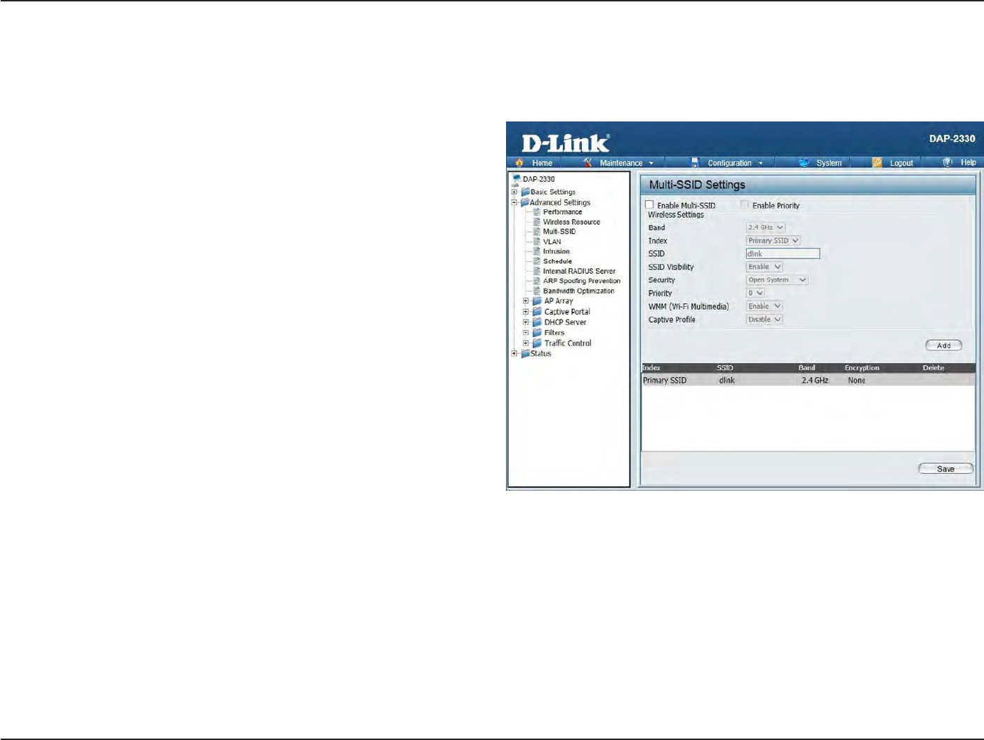
30
D
-
Link
D
A
P
-
2330
U
ser
M
anual
S
e
c
tion
3
-
C
onfigu
r
a
tion
Multi-SSID
The device supports
up to four multiple
S
ervic
e
Set
Iden
tifiers
.
You can set
the
Primary
SSID
in the
Basic
>
Wireless section. The
SSID’s
factory
default setting is dlink
.
The SSID can
be
easily changed
to
connect
to
an existing wireless network
or to
establish a new wireless
net
w
or
k
.
Enable Multi-SSID:
B
and:
I
nde
x:
SSID:
SSID
V
isibilit
y
:
S
ecurit
y
:
P
riorit
y
:
WMM
(
Wi-F
i
Multimedia):
Captive
P
r
ofile:
Check
to
enable
support
for multiple
SSIDs
.
S
elec
t
2.4GHz
in
default
.
You can
selec
t
up to
three multi-SSIDs.
With the
P
rimar
y
SSID, you have a
total of
four
multi-SSIDs
.
S
ervic
e
Set
Identifier
(SSID) is
the
name designa
t
ed
for a
specific wireless local area
network
(WLAN). The
SSID
’
s
factory default setting is
dli
n
k
.
The SSID can
be easily
changed
to
c
onnec
t
to
an existing wireless network or
t
o
establish a new wireless
net
w
or
k
.
Enable
or
Disable SSID visibilit
y
.
Enabling
this feature
broadcasts
the
SSID across
the
net
w
or
k
,
thus
making
it
visible
to
all network
users.
The Multi-SSID security
can be Open
S
ystem,
W
P
A-
Personal,
or
W
P
A
-En
t
er
pr
ise
.
For a
detailed description
of
the
Open
S
yst
em
parameters please
go to
page 23.
F
or
a detailed
description
of the
WPA-Personal
parameters
please
go to
page 24. For
a detailed
description
of the
W
P
A
-En
t
er
pr
ise
parameters please go
to
page
25.
S
elec
t
the
priority
level
of
the SSID
selec
t
ed
.
WMM stands
for
Wi-Fi Multimedia. Enabling
this feature
will improve the
user experience
for audio and video
applications over
a
Wi-Fi
net
w
or
k
.
Enableordisable
captiv
e
por
t
pr
ofile
f
or
user
authentication.

31
D
-
Link
D
A
P
-
2330
U
ser
M
anual
S
e
c
tion
3
-
C
onfigu
r
a
tion
Encr
yption:
Key
T
ype:
Key
Size:
Key
Index
(1-4):
Ke
y
:
WPA
Mode:
Cipher
T
ype:
Group Key
Upda
t
e
I
n
t
er
v
al:
Pass P
hr
ase:
C
onfirm
Pass P
hr
ase:
RADIUS
S
er
v
er:
RADIUS
P
or
t:
RADIUS
S
ecr
et:
When
you
selec
t
Open
S
ystem,
toggle
between Enable and Disable
.
If
Enable is selec
t
ed
,
the
Key Type, Key Size, Key
Index
(1~4), Key,
and Confirm
Keys must also be
c
onfigur
ed
.
S
elec
t
HEX or ASCII.
S
elec
t
64-bit or 128-bit
.
S
elec
t
from the 1st
to 4th
key
to
be set as
the active key
.
Input up to
four keys
for
encr
yption.
You
will
selec
t
one
of
these keys
in
the Key
Index drop-down
menu
.
W
hen
y
ou
selec
t
either
W
P
A
-P
ersonal
or
W
P
A
-En
t
er
pr
ise
,
y
ou
must
also
choose
a
W
P
A
mode
fr
om
the
drop
-
do
wn
menu:
AUTO
(
W
P
A
or
W
P
A2),
W
P
A2
Only
,
or
W
P
A
Only
.
W
P
A
and
W
P
A2
use
diff
eren
t
algorithms
.
A
UT
O
(
W
P
A
or
W
P
A2)
allo
w
s
y
ou
to
use
both
WPA
and
WPA2.
In addition, you must configure
C
ipher
Type, and Group Key
Upda
t
e
I
n
t
er
v
al
.
S
elec
t
A
ut
o
,
AES,
or
TKIP
from the drop-down menu
.
S
elec
t
the interval
during
which the
group
key
will
be
valid
.
The default value
of
1800 seconds is
r
ec
ommended
.
When you
selec
t
WPA-Personal, please
enter
a Pass
Phrase
in
the corresponding field
.
When you
selec
t
WPA-Personal, please
r
e
-en
t
er
the
Pass
Phrase
en
t
ered
in
the previous
item in
the corresponding field
.
When you
selec
t
W
P
A
-En
t
er
pr
ise
,
enter the
IP
address
of
the RADIUS server.
In addition, you must configure
RADIUS
P
or
t
and
RADIUS
S
ecr
et
.
En
t
er
the RADIUS por
t
.
En
t
er
the RADIUS
secr
et
.
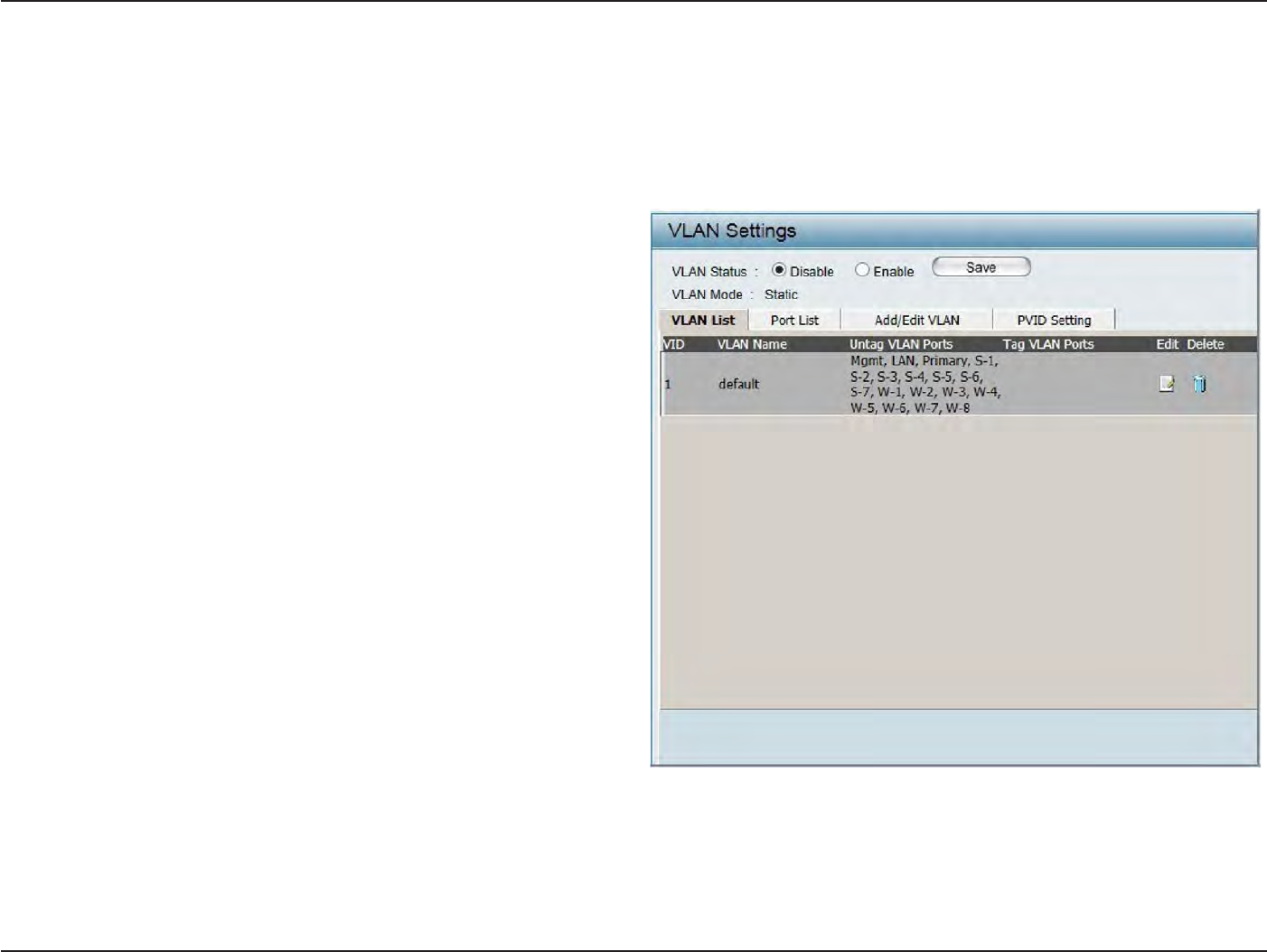
32
D
-
Link
D
A
P
-
2330
U
ser
M
anual
S
e
c
tion
3
-
C
onfigu
r
a
tion
VL
AN
VLAN
List
The DAP-2330 supports
VLANs. VLANs can
be
cr
ea
t
ed
with
a Name and VID.
Mgmt
(TCP stack), LAN,
P
rimar
y/M
ultiple
SSID, and WDS
connection
can
be
assigned
to
VLANs as
they
are physical ports
.
Any packet which en
t
ers
the
DAP-2330
without
a VLAN
tag will
have a VLAN
tag inserted
with
a PVID. The VLAN List
tab
displays
the
current
VLANs
.
VLAN
S
ta
tus:
VLAN
Mode:
U
se
the
radio
button
t
o
t
oggle
t
o
Enable
.
Ne
x
t
,
go
to
the
Add/E
dit
VLAN tab
to
add or
modify
an
item
on the
VLAN List
tab
.
The
cur
r
en
t
VLAN mode is
displayed
.
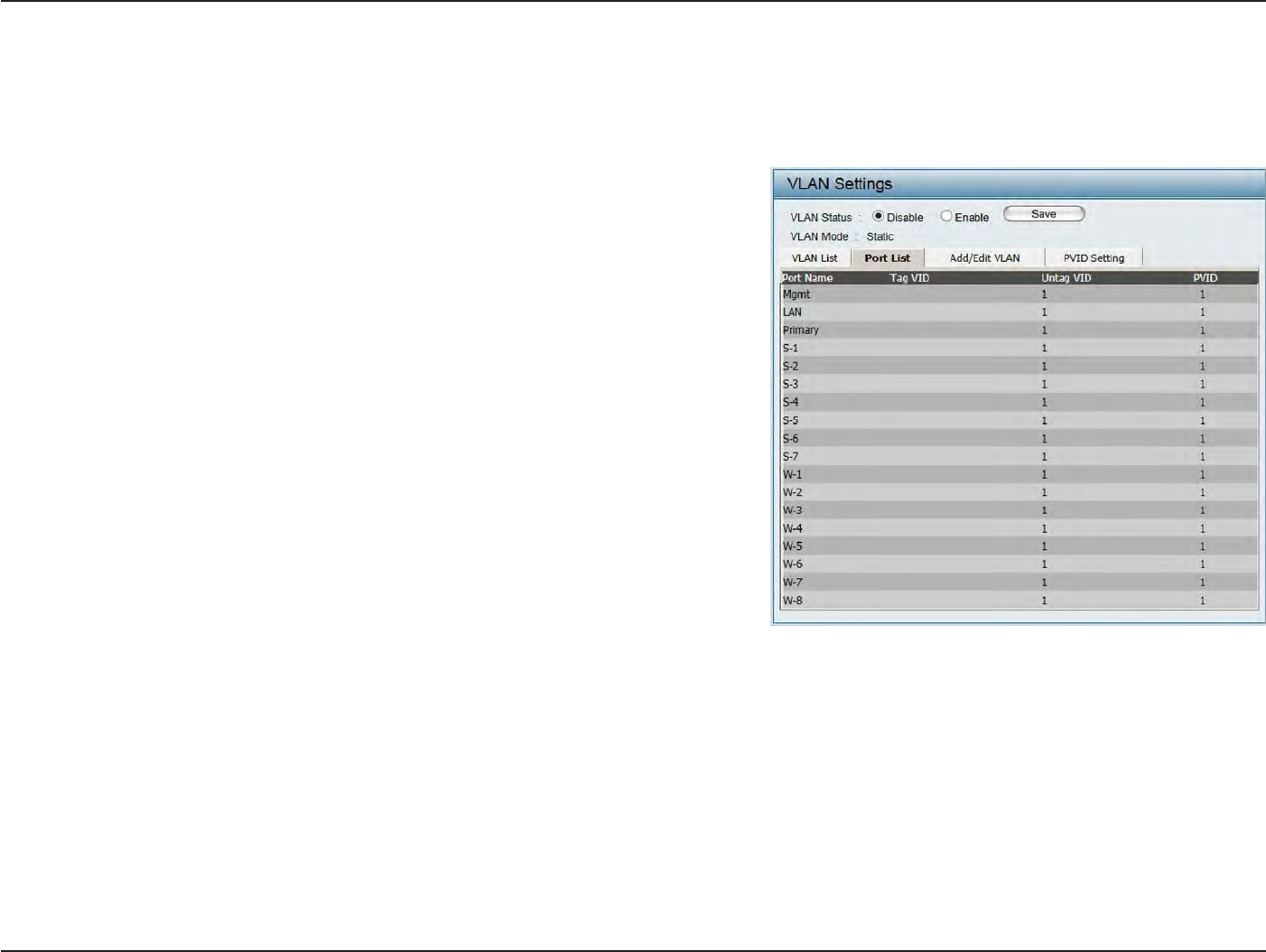
33
D
-
Link
D
A
P
-
2330
U
ser
M
anual
S
e
c
tion
3
-
C
onfigu
r
a
tion
P
or
t
List
The
P
or
t
List
tab
displays
the
current por
ts
.
If
you
want to
configure
the
guest and internal networks
on
a Virtual LAN (VLAN),
the
switch
and
DHCP server you are using must also
support
VLANs. As a
prerequisite
st
ep
,
configure a
port on the
switch
for
handling
VLAN tagged packets as
described
in the
IEEE
802.1Q
standar
d
.
VLAN
S
ta
tus:
P
or
t
Name:
T
ag
VID:
Un
tag
VID:
P
VID:
Use
the
radio
button to toggle to
Enable
.
Ne
x
t
,
go to the Add/Edit
VLAN tab
to
add or modify an
item
on the
VLAN List
tab
.
The name
of
the
port
is displayed
in
this
column.
T
he
T
agged
VID is displayed
in
this
column.
The Untagged VID is displayed
in
this
column.
The
P
or
t
VLAN
Identifier
is displayed
in
this
column.
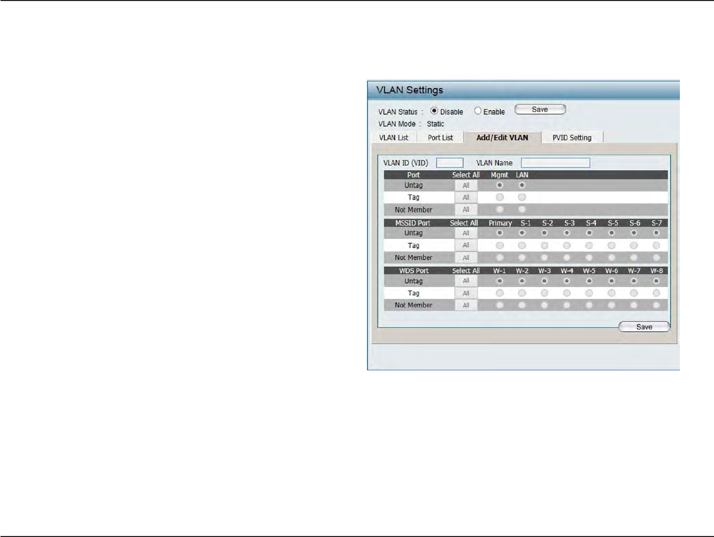
34
D
-
Link
D
A
P
-
2330
U
ser
M
anual
S
e
c
tion
3
-
C
onfigu
r
a
tion
Add/Edit
VL
AN
The Add/Edit VLAN
tab
is used
to
configure
VLANs. Once you have made
the
desired changes
,
click
the
Save
button to let
your changes
take
eff
ec
t
.
VLAN
S
ta
tus:
VLAN ID:
VLAN Name:
Use
the
radio
button to toggle to
Enable
.
Provide a number between
1
and
4094
for the
Internal
VLAN.
En
t
er
the VLAN
to
add
or
modify
.
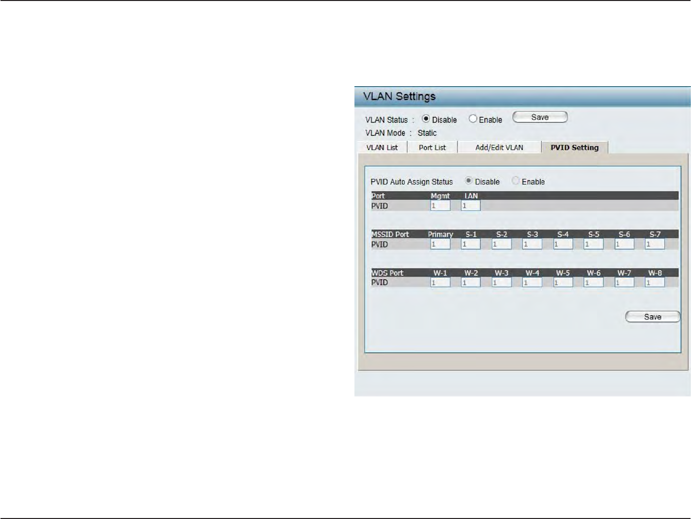
35
D
-
Link
D
A
P
-
2330
U
ser
M
anual
S
e
c
tion
3
-
C
onfigu
r
a
tion
PVID
S
ettings
The PVID
S
etting
tab
is used
to
enable/disable
the
P
or
t
VLAN
Identifier
Auto
Assign
S
ta
tus
as
well
as
to
configure various
t
ypes
of
PVID
settings
.
Click
the
Save
button to let
your changes take
eff
ec
t
.
VLAN
S
ta
tus:
PVID
Auto
Assign
S
ta
tus:
Use
the
radio
button to toggle between
Enable and Disable
.
Use
the
radio
button to toggle
PVID
auto
assign status
to
Enable
.
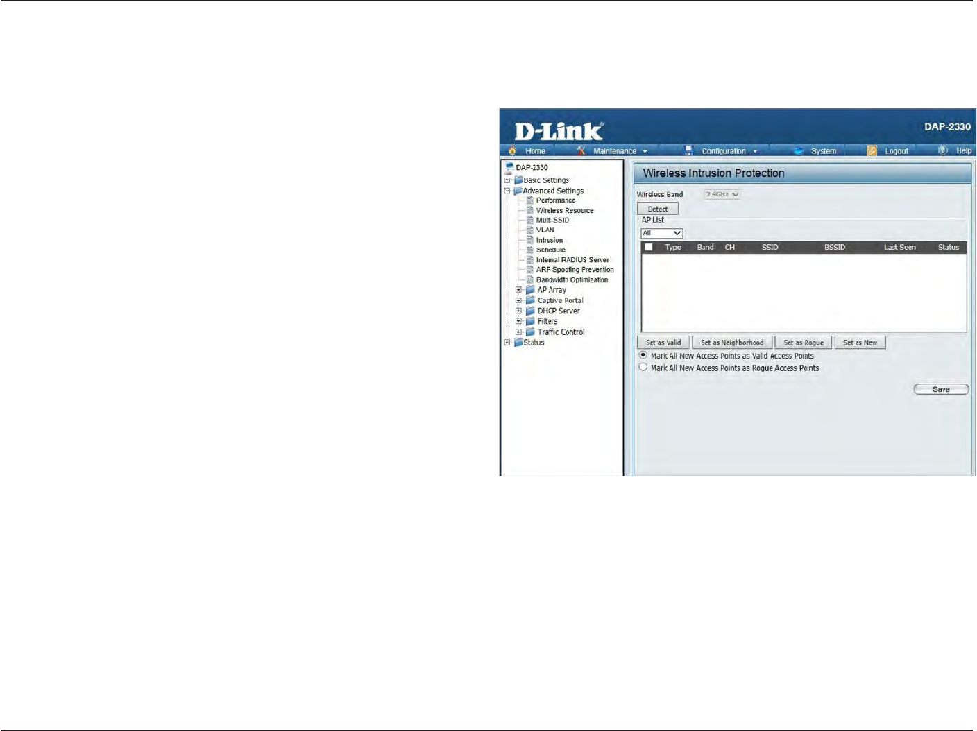
36
D
-
Link
D
A
P
-
2330
U
ser
M
anual
S
e
c
tion
3
-
C
onfigu
r
a
tion
I
ntrusion
T
he
Wireless Intrusion
P
r
ot
ec
tion
window
is used
to
set APs as
A
ll
,
V
alid
,
Neighborhood
,
R
ogue
,
and New
.
Click
the
Save
button to let
your
changes
take
eff
ec
t
.
Wireless
B
and:
AP
List:
Det
ec
t:
S
elec
t
2.4GHz
in
default
.
The choices include A
ll
,
V
alid
,
Neighbor
,
R
ogue
,
and New
.
Click this
button to initiate
a scan
of the
net
w
or
k
.
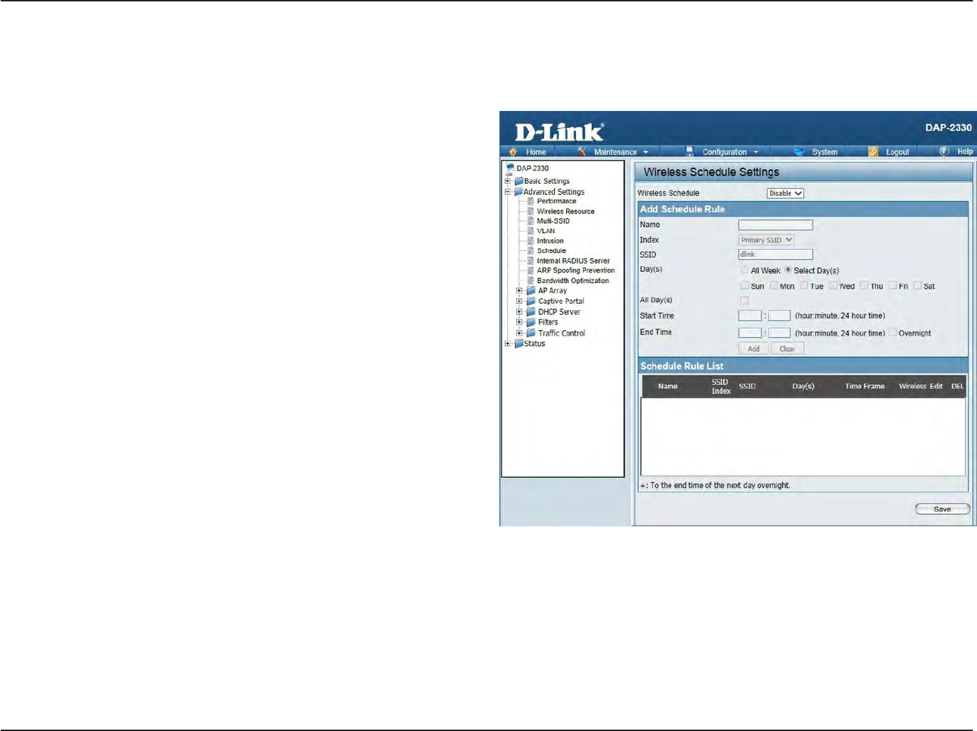
37
D
-
Link
D
A
P
-
2330
U
ser
M
anual
S
e
c
tion
3
-
C
onfigu
r
a
tion
S
chedule
The Wireless
S
chedule
S
ettings
window
is used
to
add and
modify
scheduling rules
on the
devic
e
.
Click
the
Save
button to let
your changes
take
eff
ec
t
.
Wireless
S
chedule:
Name:
I
nde
x:
SSID:
Da
y(s):
All
Da
y(s):
S
tar
t
T
ime:
End
T
ime:
Use
the drop-down menu to
enable
the
devic
e
’
s
scheduling
f
ea
tur
e
.
En
t
er
a name
for the
new scheduling rule
in the field
pr
ovided
.
Use
the drop-down menu
to
selec
t
the desired
SSID
.
T
his
r
ead-
only
field
indica
t
es
the
cur
r
en
t
SSID
in
use
.
T
o
cr
ea
t
e
a
new
SSID
,
go
to
the
Wireless
S
ettings
windo
w
(Basic
S
ettings
>
W
ir
eless).
Toggle the radio
button
between
A
ll
Week and
S
elec
t
Day(s).
If the
second
option
is
s
e
l
ec
t
e
d
,
check
the
specific days
you want the rule
to
be effective
on.
Check
this box to
have
your
settings
apply 24 hours
a
day
.
En
t
er
the
beg
inning
hour
and
minut
e
,
using
a
24-hour
clock
.
En
t
er
the ending hour and
minut
e
,
using a 24-hour
clock
.
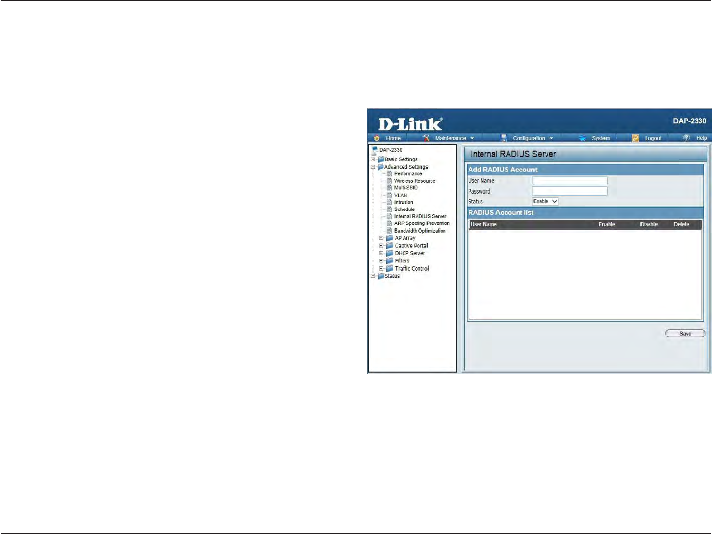
38
D
-
Link
D
A
P
-
2330
U
ser
M
anual
S
e
c
tion
3
-
C
onfigu
r
a
tion
Internal
RADIUS
S
er
v
er
The DAP-2330 features a
built-in
RADIUS
ser
v
er
.
Once
you
have finished adding
a RADIUS
acc
oun
t
,
click
the
Save
button to let
your changes
take
eff
ec
t
.
T
he
newly
-cr
ea
t
ed
acc
oun
t
will
appear
in
this
RADIUS
Account
List
.
T
he
radio
buttons allow the
user
to
enable
or
disable
the
RADIUS
acc
oun
t
.
Click
the
icon
in the
delete column
to
remove
the
RADIUS
acc
oun
t
.
We suggest you
limit the
number
of
accounts
below 30.
User
Name:
P
assw
or
d:
S
ta
tus:
RADIUS
A
cc
oun
t
List:
En
t
er
a name to authenticate
user access
to the
internal
RADIUS
ser
v
er
.
En
t
er
a password
to
authenticate
user access
to the
internal
RADIUS server. The
length of
your
password
should be
8~64.
Toggle
the drop-down menu between
E
n
a
b
l
e
and
Disable
.
Displays the list
of
users.
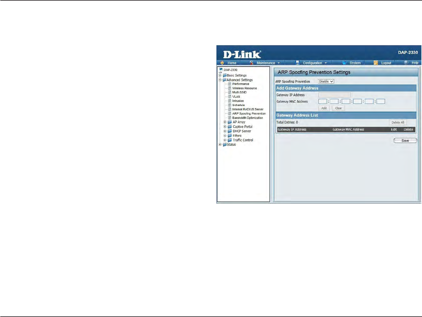
39
D
-
Link
D
A
P
-
2330
U
ser
M
anual
S
e
c
tion
3
-
C
onfigu
r
a
tion
ARP
Spoofing
P
r
e
v
en
tion
The ARP
Spoofing Prevention feature allows users
to
add IP/MAC address
mapping to
prevent arp spoofing
a
ttack
.
ARP
Spoofing
P
r
e
v
en
tion:
G
a
t
e
w
a
y
IP
A
ddr
ess:
G
a
t
e
w
a
y
MAC A
ddr
ess:
This check
box
allows
you to
enable
the arp
spoofing prevention
function.
En
t
er
a
ga
t
ew
a
y
IP
addr
ess
.
En
t
er
a
ga
t
ew
a
y
MAC
addr
ess
.
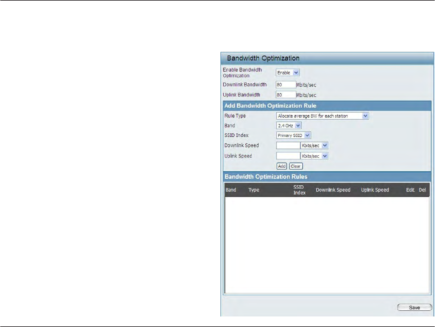
40
D
-
Link
D
A
P
-
2330
U
ser
M
anual
S
e
c
tion
3
-
C
onfigu
r
a
tion
Bandwidth
O
ptimiza
tion
T
he
Bandwidth Optimiza
tion
windo
w
allo
w
s
the
user
to
manage
the
bandwidth of
the
device and arrange
the
bandwidth
f
or
various
wir
eless
clien
ts
.
When
the
Bandwidth Optimization ruile
is
finished
,
click
the
Add
button.
To discard
the
Add Bandwidth Optimization
Rule
settings
,
click
the
C
lear
button.
Click
the
Save
button to let
your changes take
eff
ec
t
.
Enable
B
andwidth
O
ptimization:
Downlink Bandwidth:
Uplink
B
andwidth:
A
lloca
t
e
average
B
W
for
each sta
tion:
A
lloca
t
e
maximum
B
W
for
each sta
tion:
A
lloca
t
e
different
B
W
for b/g/n
sta
tions:
A
lloca
t
e
specific
B
W
for
SSID:
Rule
Type:
U
se
the
drop
-
do
wn
menu
t
o
Enable
the Bandwidth
Optimization
function.
En
t
er
the downlink bandwidth of the
device
in
Mbits per
sec
ond
.
En
t
er
the
uplink bandwidth of
the
devic
e
in
Mbits
per
sec
ond
.
AP
will distribute
average
bandwidth for each
clien
t
.
S
p
ec
if
y
the maximum bandwidth for each
c
onnec
t
ed
clien
t
.
Reserve certain
bandwidth for
future clien
ts
.
T
he
w
eigh
t
of 11b/g/n
client
ar
e
10%/20%/70% ;
20%/80%. AP
will
distribute different
bandwidth
for 11b/g/n
clien
ts
.
All clients share the
total bandwidth.
Use
the drop-down menu to
s
e
l
ec
t
the type
that
is applied
to the
rule
.
Available options
are:
A
llo
c
a
t
e
av
er
age
B
W
f
or
each
sta
tion
,
A
llo
c
a
t
e
maximum
BW
for each
sta
tion
,
A
llo
c
a
t
e
differ
en
t
B
W
f
or
11
b/g/n
sta
tions
,
and
A
llo
c
t
e
specific
B
W
for
SSID
.

41
D
-
Link
D
A
P
-
2330
U
ser
M
anual
S
e
c
tion
3
-
C
onfigu
r
a
tion
B
and:
SSID
I
nde
x:
Downlink
Speed:
Uplink
Speed:
Use
the drop-down menu
to toggle
the wireless band between
2.4GH
z.
Use
the drop-down menu
to
selec
t
the SSID
for
the specified wireless
band
.
En
t
er
the
limitation of
the downloading
speed
in
either Kbits/sec or Mbits/sec
for
the rule
.
En
t
er
the
limitation of
the uploading speed
in
either Kbits/sec or Mbits/sec
for
the rule
.
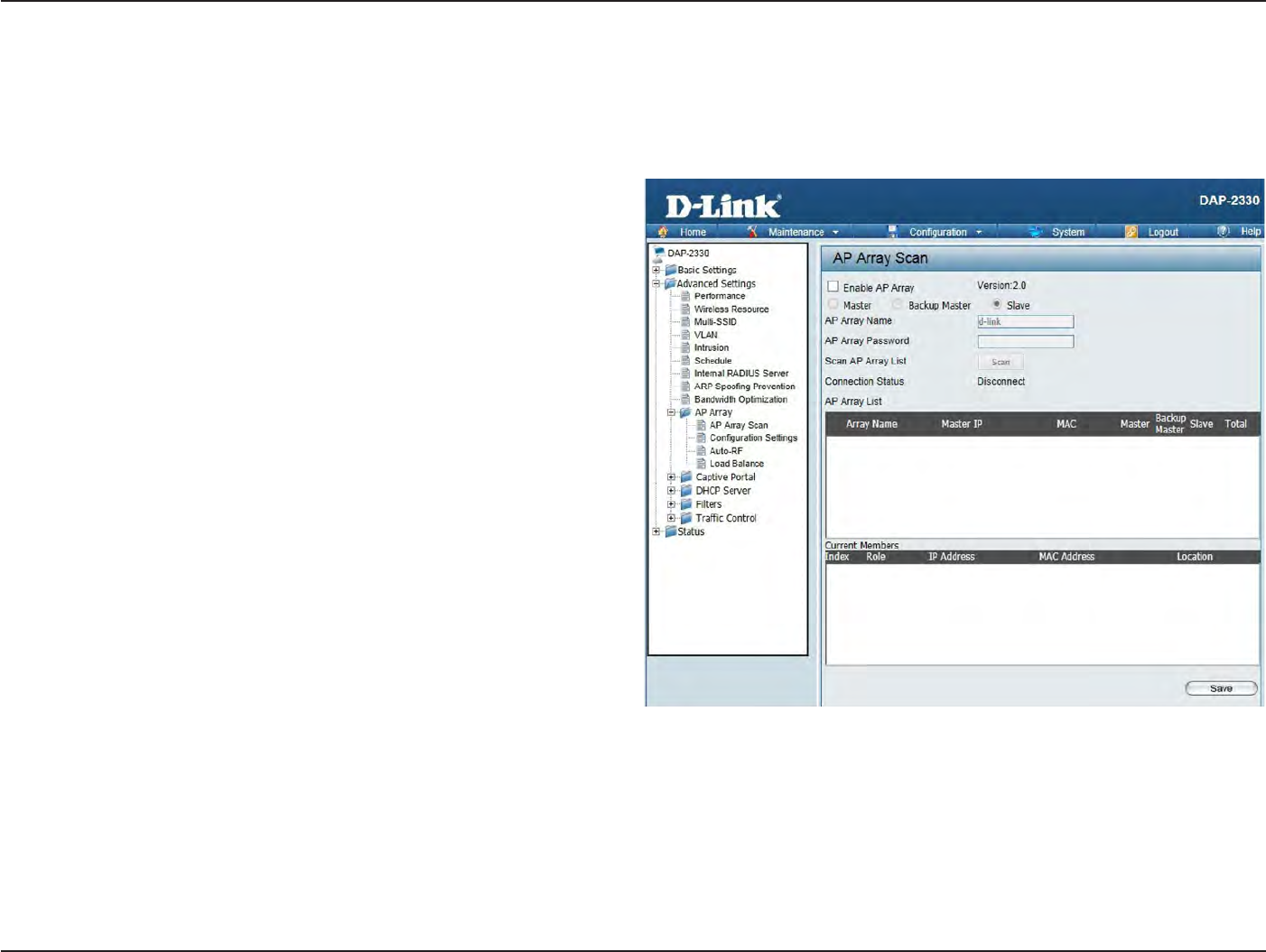
42
D
-
Link
D
A
P
-
2330
U
ser
M
anual
S
e
c
tion
3
-
C
onfigu
r
a
tion
AP
A
rr
a
y
AP Array
S
can
The AP Array
window
is used
to
cr
ea
t
e
up to
32 APs on a
local network
to
be organized
into
a
single group
in
order
to
increase ease
of
managemen
t
.
Click
the
Save
button to let
your changes take
eff
ec
t
.
Central WiFiManager and AP Array are
mutually
exclusive
functions
.
Enable AP A
rr
a
y
:
AP Array
Name:
AP Array
P
assw
or
d:
Scan AP Array
List:
C
onnec
tion
S
ta
tus:
AP Array
List:
C
urr
en
t
Members:
S
elec
t
the
check
box to
enable
the
AP
array
function. The three modes
that
are available
are
M
ast
er
,
Backup
M
ast
er
,
and
S
l
ave
.
APs
in the
same array
will
use
the
same configuration.
T
he
c
onfigur
a
tion
will
sync
the
M
ast
er
AP
t
o
the
Sla
v
e
AP
and
the
Back
up
M
ast
er
AP
when
a
Sla
v
e
AP
and
a Backup Master AP
join
the AP
ar
r
a
y
.
En
t
er
an AP array name
for
the
group
her
e
.
En
t
er
an
AP array password
for the group
her
e
.
This password
must be the
same
on all the
AP
s
in
the gr
oup
.
Click
this button to initiate a
scan
of all the
available
APs
currently on the net
w
or
k
.
Display the AP
array connection
sta
tus
.
This table displays
the current
AP array status
for
the following
p
aram
et
e
rs
:
Array Nam
e
,
M
as
t
er
IP,
MAC,
M
ast
er
,
Backup
M
ast
er
,
Slave,
and
T
otal
.
T
his
table displays all
the
current
ar
r
a
y
members
.
The DAP-2330 AP array feature supports
up
t
o
eight
AP array
members
.
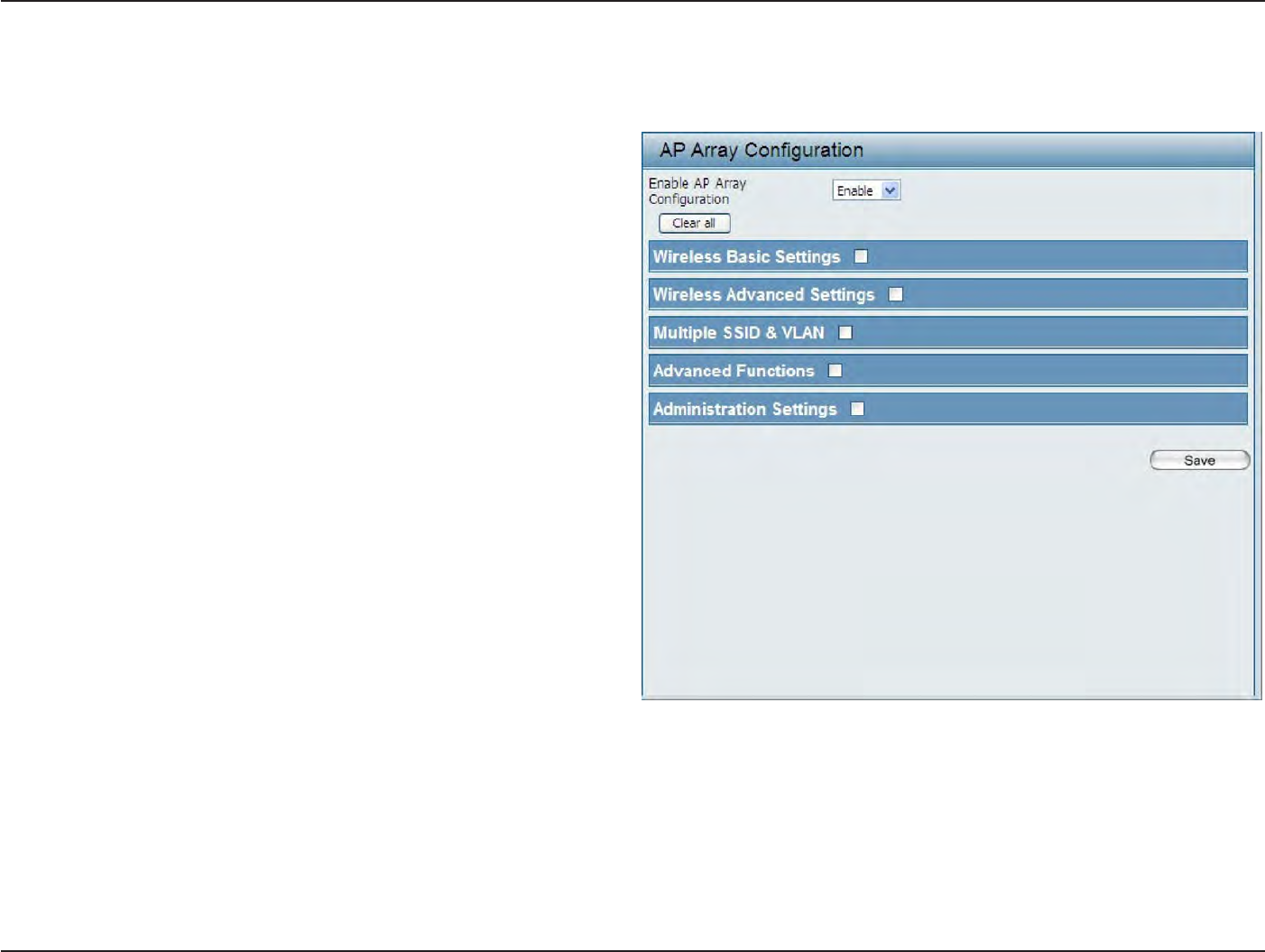
43
D
-
Link
D
A
P
-
2330
U
ser
M
anual
S
e
c
tion
3
-
C
onfigu
r
a
tion
C
onfigur
a
tion
S
ettings
In the
AP array
configuration settings windo
w
s
,
users can specify which settings all
the
APs
in the group will inherit from the
master AP. Make
the
required selection
in
this
window
and click
the
Save
button to
accept
the
changes made
.
Enable AP A
rr
a
y
C
onfigur
a
tion:
Wireless
Basic
S
ettings:
Wireless
Advanced
S
ettings:
Multiple
SSID &
VL
AN:
Advanced
F
unc
tions:
A
dministr
a
tion
S
ettings:
S
elec
t
t
o
Enable
or
D
isable
the
AP
ar
r
a
y
configure
feature her
e
.
S
elec
t
this option to
specify
the
basic
wir
eless
settings
that
the APs
in
the
group will
inher
it
.
S
e
l
ec
t
t
h
i
s
o
p
t
i
on
t
o
s
p
ec
if
y
t
h
e
a
d
v
a
n
ce
d
w
i
r
e
l
e
ss
settings
that
the APs
in
the
group will
inher
it
.
S
elec
t
this option to
specify
the multiple
SSIDs
and VLAN settings
that the
APs
in the group
will
inher
it
.
S
elec
t
this
option to
specify
the other advanced
settings
that
the APs
in
the
group will
inher
it
.
S
elec
t
this option to
specify
the administrative
settings
that
the APs
in
the
group will
inher
it
.
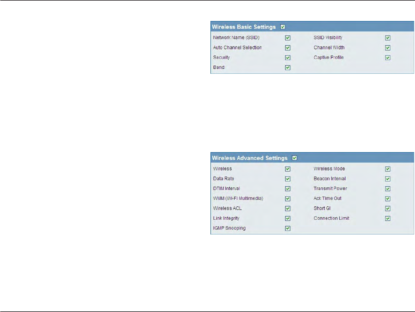
44
D
-
Link
D
A
P
-
2330
U
ser
M
anual
S
e
c
tion
3
-
C
onfigu
r
a
tion
Wireless Basic
S
ettings
Network
Name
(SSID
):
SSID
V
isibilit
y
:
Auto
Channel
S
elec
tion:
Channel W
idth:
S
ecurit
y
:
Captive
P
r
ofile:
B
and:
S
elec
t
this
option to
use the same
SSID
.
S
elec
t
this
option to
enable
SSID visibilit
y
.
S
elec
t
this
option to
use auto channel
selection.
S
elec
t
this
option
t
o
use
the
same
channel
width.
S
elec
t
this
option to
use the same wireless secur
it
y
.
S
elec
t
this
option to
use the same captive profile
settings
.
S
elec
t
this
option to
use the same wireless
band
.
Wireless Advanced
S
ettings
W
ir
eless:
Wireless
Mode:
Data
R
a
t
e:
Beacon I
n
t
er
v
al:
DTIM I
n
t
er
v
al:
Transmit
P
ow
er:
WMM
(
Wi-F
i
Multimedia):
Ack Time
O
ut:
Wireless A
CL:
S
e
le
c
t
thi
s
option to
use
the
same
wi
r
e
le
ss
settings
.
S
elec
t
this
option
t
o
use
the
same
wir
eless
mode
.
S
elec
t
this
option to
use the same data
r
a
t
e
.
S
elec
t
this
option
t
o
use
the
same
beac
on
in
t
er
v
al
.
S
elec
t
this
option to
use the same DTIM
in
t
er
v
al
.
S
elec
t
this
option to
use the same transmit po
w
er
.
S
elec
t
this
option to
use the same
WMM settings
.
S
elec
t
this
option to
use the same ACK
timeout
v
alue
.
S
elec
t
this
option to
use the same wireless ACL
settings
.
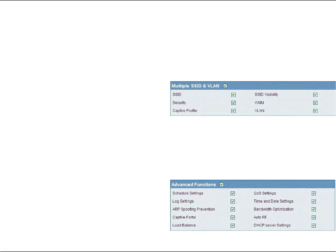
45
D
-
Link
D
A
P
-
2330
U
ser
M
anual
S
e
c
tion
3
-
C
onfigu
r
a
tion
S
hor
t
GI:
Link
I
n
t
eg
rit
y
:
C
onnec
tion
Limit:
IGMP
Snooping::
S
elec
t
this
option to
use the same
short
GI
settings
. S
elec
t
this
option to
use the same link
integrity
settings
. S
elec
t
this
option to
use the same connection
limit
v
alue
.
S
elec
t
this
option to
use the same IGMP
snooping
settings
.
Multiple
SSID &
VL
AN
SSID:
SSID
V
isibilit
y
:
S
ecurit
y
:
WMM:
Captive
P
r
ofile:
VL
AN:
S
elec
t
this
option to
use the same multi-SSIDs
.
S
elec
t
this
option to
use the same SSID
visible
.
S
elec
t
this
option
t
o
use
the
same
wir
eless
security
settings
.
S
elec
t
this
option to
use the same
WMM settings
.
S
elec
t
this
option to
use the same captive profile
settings
.
S
elec
t
this
option to
use the same
VLAN
settings
.
Advanced
F
unc
tions
S
chedule
S
ettings:
QoS
S
ettings:
Log
S
ettings:
Time
and
Da
t
e
S
ettings:
S
elec
t
this option to
use
the
same
schedule
settings
.
S
elec
t
this option to
use
the
same
Quality of
S
ervic
e
settings
.
S
elec
t
this
option to
use the same
log
settings
.
S
elec
t
this
option to
use the same
time
and
date
settings
.
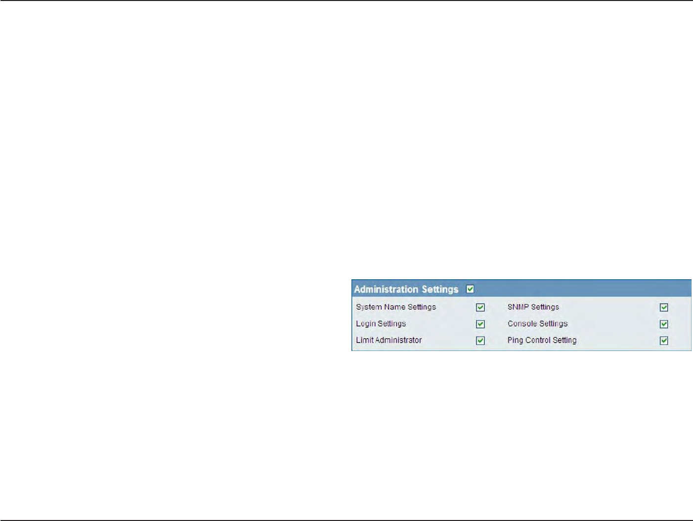
46
D
-
Link
D
A
P
-
2330
U
ser
M
anual
S
e
c
tion
3
-
C
onfigu
r
a
tion
ARP
Spoofing
P
r
e
v
en
tion:
B
andwidth
O
ptimization:
Captive
P
ortal:
Auto
RF
:
Load
B
alanc
e:
DHCP
S
er
v
er
S
ettings:
S
elec
t
this
option to
use the same ARP
spoofing prevention
settings
.
S
elec
t
this
option to
use the same
bandwidth
optimization
settings
.
S
elec
t
this
option to
use the same captive portal
settings
.
S
elec
t
this
option to
use the same auto-RF
settings
.
S
elec
t
this
option to
use the same load balancing
settings
.
S
elec
t
this
option to
use the same DHCP server
settings
.
Administration
S
ettings
S
y
stem
Name
S
ettings:
SNMP
S
ettings:
Login
S
ettings:
Console
S
ettings:
Limit
A
dministr
a
t
or:
Ping
C
on
tr
ol
S
etting:
S
elec
t
this
option to
use the same system
name
.
S
elec
t
this
option
t
o
use
the
same
SNMP
settings
.
S
elec
t
this
option to
use the same
login
settings
.
S
elec
t
this
option to
use the same console
settings
.
S
elec
t
this
option to
use the same
limit
administrator
settings
.
S
elec
t
this
option to
use the same
ping
control
settings
.
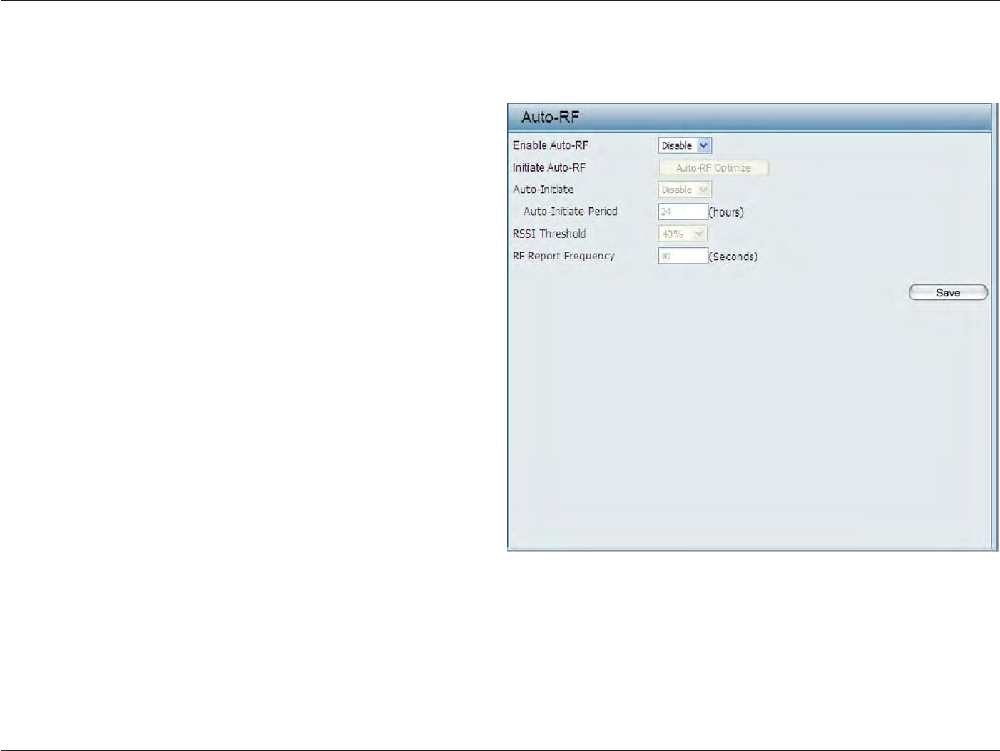
47
D
-
Link
D
A
P
-
2330
U
ser
M
anual
S
e
c
tion
3
-
C
onfigu
r
a
tion
A
ut
o
-RF
I
n
this
windo
w
s
,
users
can
view
and
configure the
automatic radio frequency settings
as
well
as
configure the
the
auto-initiate period
and
threshold
v
alues
.
Click
the
Save
button to
accept
the
changes made
.
Enable: A
ut
o
-RF:
Initiate
A
ut
o
-RF:
A
ut
o
-I
nitia
t
e:
Auto-Initiate
P
eriod:
RSSI
T
hr
eshold:
RF R
epor
t
F
r
equenc
y
:
S
elec
t
to
Enable
or
Disable
the
auto-RF
feature
her
e
.
C
li
ck
th
e
A
ut
o
-RF
O
ptimiz
e
button
t
o
i
ni
ti
a
t
e
the
auto-RF
optimization
f
ea
tur
e
.
S
el
ec
t
the
Enable
or
Disable
the auto-initiate
feature her
e
.
A
f
t
er
enabling the auto-initiate option, the
auto-
initiate period
value can
be
entered
her
e
.
T
his
value must be between 1 and 24 hours
.
S
elec
t
the
RSSI
thr
eshold
v
alue
her
e
.
T
his
v
alue
is
listed
in the drop-down menu in
increments
of
10% from
10%
to
100%
.
En
t
er
the
RF
report
frequency value her
e
.
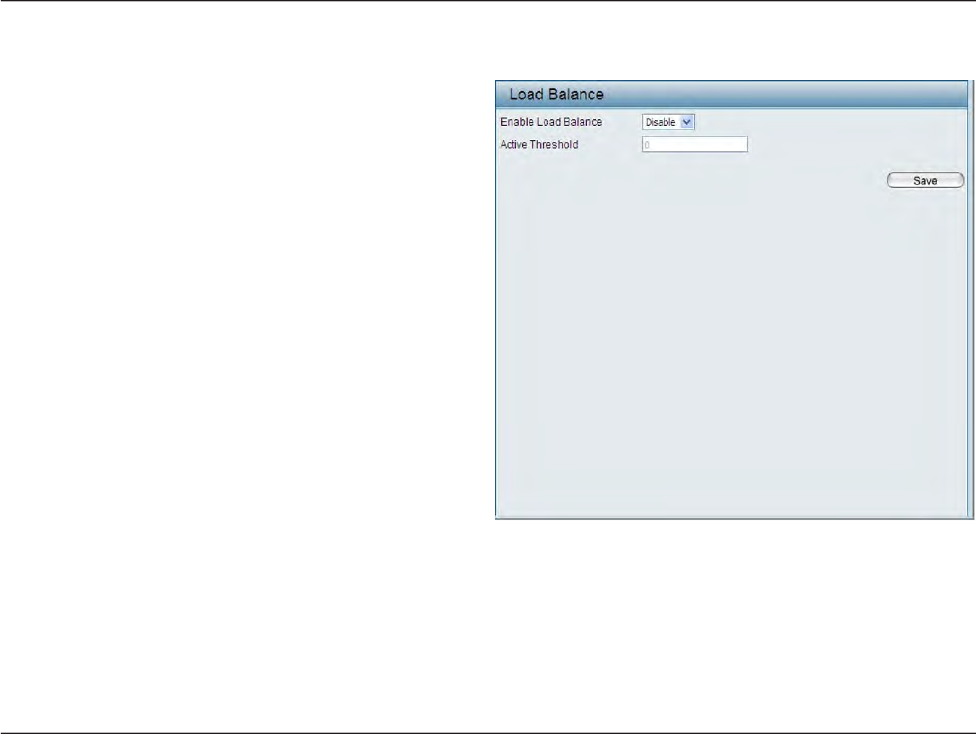
48
D
-
Link
D
A
P
-
2330
U
ser
M
anual
S
e
c
tion
3
-
C
onfigu
r
a
tion
Load
B
alance
In this windo
w
,
users can
view and configure
the
AP array’s
load balancing
settings
.
Click
the
Save
button to
accept
the
changes made
.
Enable Load
B
alanc
e:
Active
Threshold:
S
elec
t
to
Enable
or
Disable
the load balance
feature her
e
.
En
t
er
the active threshold value her
e
.

49
D
-
Link
D
A
P
-
2330
U
ser
M
anual
S
e
c
tion
3
-
C
onfigu
r
a
tion
Captive
P
or
tal
Authentication
S
ettings
-
P
assc
ode
T
he
C
a
pti
v
e
P
or
t
a
l
is
a
built-in
w
e
b
a
u
th
e
n
t
ic
a
t
i
on
se
rv
e
r
.
W
h
en
a
s
ta
t
io
n
connects
to
an
A
P
,
t
he
w
e
b
brower
will
be
r
e
di
r
ec
t
ed
to
a
w
e
b
authentication
page
.
In this windo
w
s
,
user can view and configure
the
Captive Portal settings
.
Click
the
Add
button to
add a new en
tr
y
.
Click
the
Delete
or Delete
All
button to
remove a specific entry
or
all
the
entries
c
onfigur
ed
.
Encryption
Type:
Passcode Q
uan
tit
y
:
D
ur
a
tion:
Last
Active Day:
User
Limit:
S
elec
t
the
captive
portal encryption type
her
e
.
Options to
choose
from are
Passcode
,
User
Name
/P
ass
w
o
rd
,
Remote RADIUS
,
LDAP
and
POP3
.
In this section we’ll discuss
the
P
assc
o
de
option.
En
t
er
the
number
of
Passcode
that will be used
her
e
.
Enter the duration
v
alue
,
in
hours
,
for this
P
assc
ode
.
S
elec
t
the
last active
date
for
this Passcode
her
e
.
Y
ear
,
Month
and
Day
selections can be made
.
En
t
er
the
maximum
amoun
t
of
users
tha
t
can
use
this Passcode
at the
same time
.
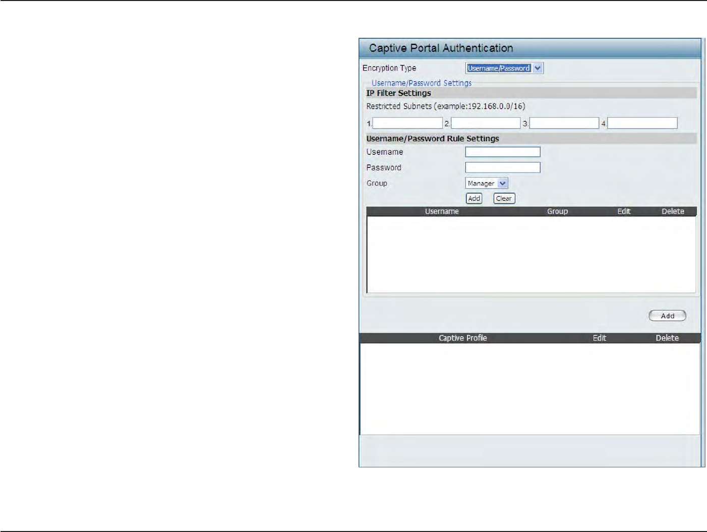
50
D
-
Link
D
A
P
-
2330
U
ser
M
anual
S
e
c
tion
3
-
C
onfigu
r
a
tion
Encryption
T
ype:
R
estric
t
ed
Subnets:
Username:
P
assw
or
d:
G
r
oup:
Authentication
S
ettings
-
User
Name/Password
S
elec
t
the
captive
portal encryption type
her
e
.
Options to
choose
from are
Passcode
,
User
Name
/P
ass
w
o
rd
,
Remote RADIUS
,
LDAP
and
POP3
.
I
n
this
sec
tion
w
e
’ll
discuss
the
U
ser
Name/
Password
option.
En
t
er
the
r
estric
t
ed
subnets
her
e
.
A
cc
ess
to these
subnets
will
denied
to
guest
acc
oun
ts
.
Up
to four
r
estric
t
ed
subnet entries can be
defined
.
En
t
er
the username
for
the new
acc
oun
t
her
e
.
En
t
er
the password
for
the new
acc
oun
t
her
e
.
S
elec
t
the group for the new account
her
e
.
Options
t
o
choose
fr
om
ar
e
M
anager
and
G
uest
.
Guest accounts
will
have
limited
acc
ess
.
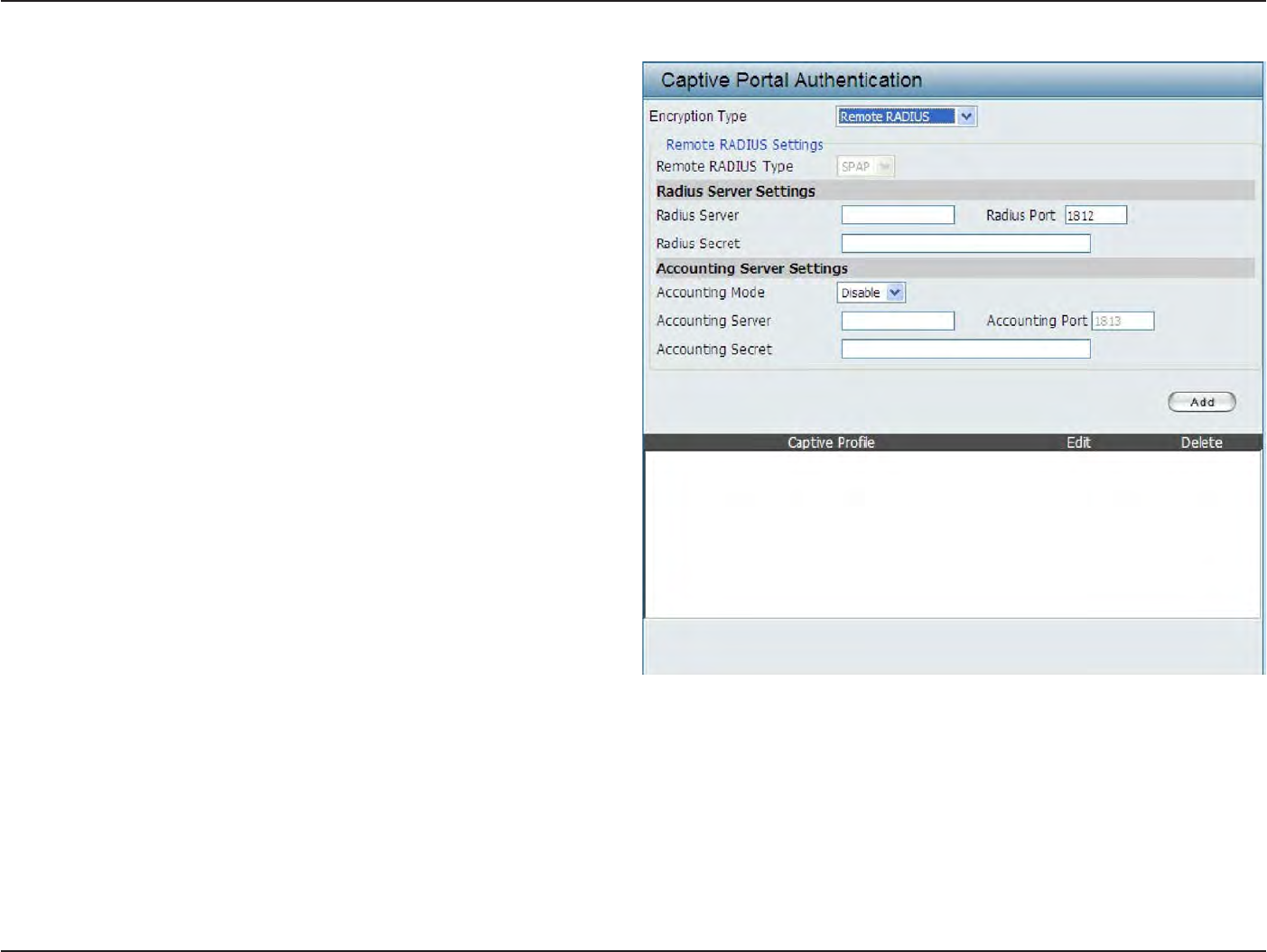
51
D
-
Link
D
A
P
-
2330
U
ser
M
anual
S
e
c
tion
3
-
C
onfigu
r
a
tion
Encryption
T
ype:
R
emot
e
RADIUS
T
ype:
RADIUS
S
er
v
er:
RADIUS
P
or
t:
RADIUS
S
ecr
et:
Accounting
Mode:
Accounting
S
er
v
er:
Accounting
P
or
t:
Accounting
S
ecr
et:
Authentication
S
ettings
-
R
emot
e
R
ADIUS
S
elec
t
the
captive
portal encryption type
her
e
.
Options to
choose
from are
Passcode
,
User
Name
/P
ass
w
o
rd
,
Remote RADIUS
,
LDAP
and
POP3
.
In this
section
we’ll
discuss
the Remote
RADIUS
option.
S
elec
t
the remote
RADIUS server
type
her
e
.
C
urr
en
tly
,
only
SPAP
will
be used
.
En
t
er
the RADIUS server’s IP address
her
e
.
Enter
the RADIUS server’s
port
number
her
e
.
En
t
er
the
RADIUS server’s shared secret
her
e
. S
elec
t
t
o
Enable
or
D
isable
the
acc
oun
ting
mode
her
e
.
En
t
er
the accounting
server’s IP address
her
e
.
En
t
er
the accounting
server’s
port
number
her
e
.
En
t
er
the accounting
server’s shared serec
t
her
e
.
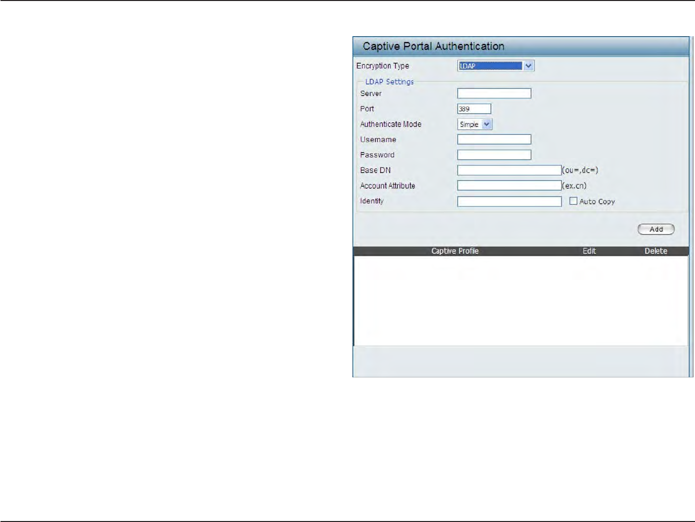
52
D
-
Link
D
A
P
-
2330
U
ser
M
anual
S
e
c
tion
3
-
C
onfigu
r
a
tion
Encryption
T
ype:
S
er
v
er:
P
or
t:
Authenticate
Mode:
Username:
P
assw
or
d:
Base
DN:
A
cc
oun
t
A
ttribut
e:
Iden
tit
y
:
Authentication
S
ettings
- LDAP
S
elec
t
the
captive
portal encryption type
her
e
.
Options
t
o
choose
fr
om
ar
e
Passo
de
,
U
ser
Name/
P
assw
or
d
,
Remote
R
ADIUS
,
LDAP
a
nd
POP3
.
In
this section we’ll discuss the
LDAP
option.
En
t
er
the
LDAP server’s IP address
or domain
name her
e
.
En
t
er
the LDAP server’s
port
number
her
e
.
S
elec
t
the authentication mode
her
e
.
Options
t
o
choose from are
Simple
and
TLS
.
En
t
er
the LDAP server
acc
oun
t
’
s
username her
e
.
En
t
er
the LDAP server
acc
oun
t
’
s
password her
e
.
En
t
er
the administr
a
t
or
’
s
domain name her
e
.
En
t
er
the
LD
AP
acc
oun
t
a
ttr
ibut
e
str
ing
her
e
.
T
his
string
will
be used
to
search
for
clien
ts
.
Enter the
iden
tit
y
’s
full path string
her
e
.
A
lt
erna
tiv
ely
,
selec
t
the
Auto Copy
checkbox
t
o
aut
oma
tically
add
the
generic
full
pa
th
of
the
web
page
in
the
identity
field
.
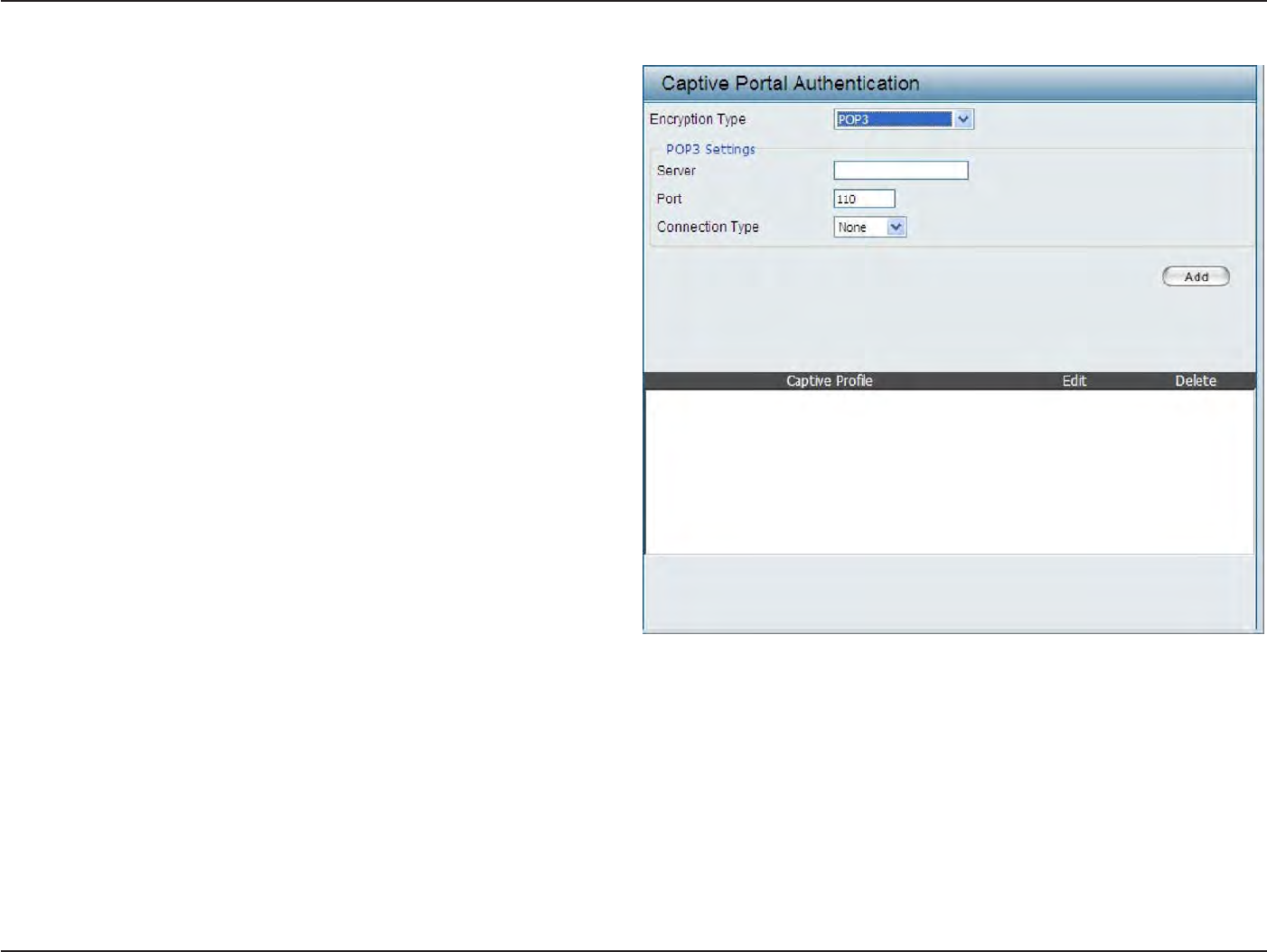
53
D
-
Link
D
A
P
-
2330
U
ser
M
anual
S
e
c
tion
3
-
C
onfigu
r
a
tion
Encryption
T
ype:
S
er
v
er:
P
or
t:
C
onnec
tion
T
ype:
Authentication
S
ettings
- POP3
S
elec
t
the
captive
portal encryption type
her
e
.
Options
t
o
choose
fr
om
ar
e
Passo
de
,
U
ser
Name/
P
a
ss
w
o
rd
,
Remote RADIUS
,
LDAP
and
P
O
P
3
.
I
n
this
section
w
e
’ll
discuss
the
Passcode
option.
E
n
t
e
r
the
POP3 server’s IP address
or domain
name her
e
.
En
t
er
the POP server’s
port
number
her
e
.
S
elec
t
the connection type
her
e
.
Options
t
o
choose from are
None
and
SSL/TLS
.
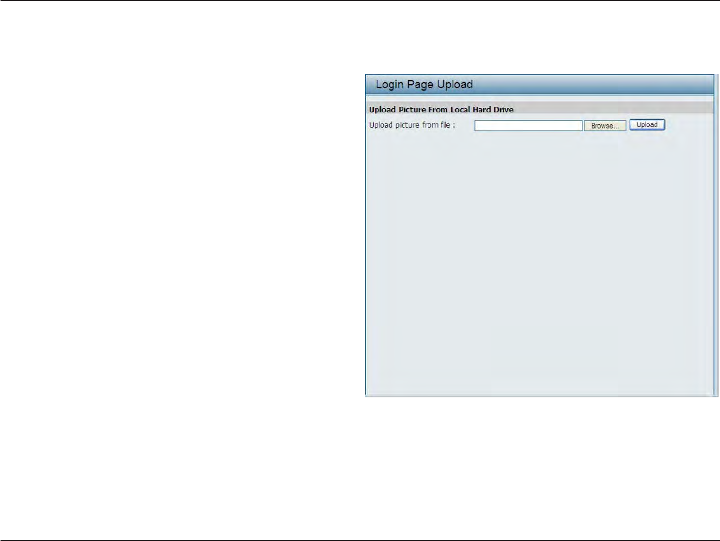
54
D
-
Link
D
A
P
-
2330
U
ser
M
anual
S
e
c
tion
3
-
C
onfigu
r
a
tion
Login
Page
Upload
In this windo
w
,
users can upload a custom
login
page picture
that will be
used
by the
captive
portal
f
ea
tur
e
.
Click
the
Browse
button to navigate
to the
image
file
,
loca
t
ed
on the
managing computer and
then
click
the
Upload
button to initiate the
upload
.
Upload picture
fr
om
file:
I
n
this
field the
pa
th
to
the
image
file
,
that will be
uploaded
,
will
be
displayed
.
A
lt
erna
tiv
ely
,
the
path
can be manually en
t
ered
her
e
.
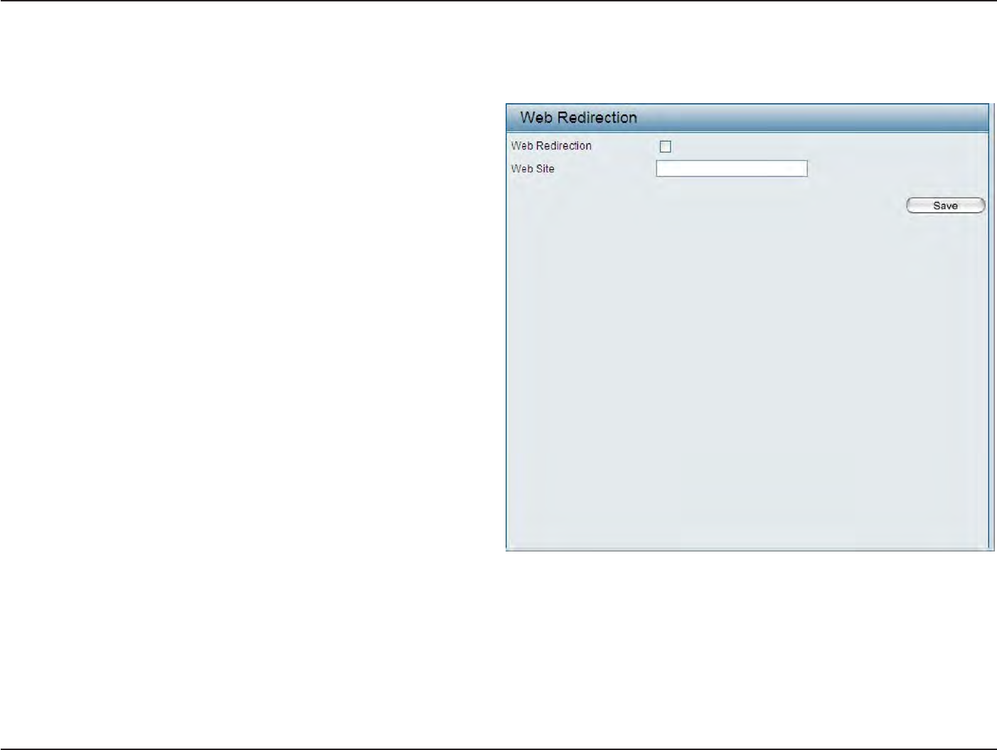
55
D
-
Link
D
A
P
-
2330
U
ser
M
anual
S
e
c
tion
3
-
C
onfigu
r
a
tion
Web
R
edir
ec
tion
In this windo
w
s
,
users can
view and configure the Web redirection settings
for the
captive
portal
hosted
by
this access poin
t
.
Wireless clients
will
be
redirected
to
this
web
site
prior
and after authentication.
Click
the
Save
button to
accept
the
changes made
.
Web
R
edir
ec
tion:
Web
Site:
S
elec
t
this
check
bo
x
t
o
enable
the
W
eb
redirection
f
ea
tur
e
.
En
t
er
the destination web
site’s address
her
e
.
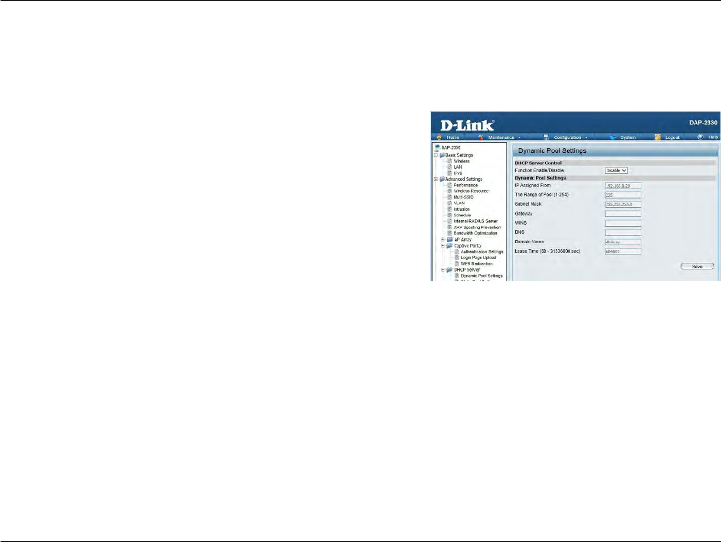
56
D
-
Link
D
A
P
-
2330
U
ser
M
anual
S
e
c
tion
3
-
C
onfigu
r
a
tion
DHCP
S
er
v
er
Dynamic Pool
S
ettings
The DHCP address
pool
defines
the
range
of the
IP address
that
can
be
assigned
to
stations
in the
net
w
or
k
.
A Dynamic Pool allows
wireless
stations
to
receive an available IP
with
lease
time
c
on
tr
ol
.
If
needed
or
required
in the
net
w
or
k
,
the
DAP-2330 is capable
of
acting as a
DHCP
ser
v
er
.
Function Enable/Disable:
IP Assigned
F
r
om:
The Range
of
Pool (1-254):
Subnet M
ask
:
G
atewa
y
:
WINS:
DNS:
Domain
Name:
Lease
T
ime:
Dynamic
Host
C
onfigur
a
tion
P
r
ot
oc
ol
(DHCP)
assigns
dynamic
IP
addr
esses
t
o
devic
es
on
the
net
w
or
k
.
T
his
protocol
simplifies
network
management
and
allows
new wireless
devices
to
receive IP addresses
automatically
without the
need
to
manually assign new
IP addresses.
S
elec
t
Enable
t
o
allow the DAP-2330
to
function
as a DHCP
ser
v
er
.
Input the first
IP address available
for
assig
nmen
t
on your
net
w
or
k
.
En
t
er
the
number
of
IP addresses available
for
assig
nmen
t
.
IP
addr
esses
ar
e
incr
ements
of
the
IP
addr
ess
specified
in
the
“IP Assigned
F
rom
”
field
.
All devices
in
the
network must
have
the
same
subnet
mask
to
c
ommunica
t
e
.
En
t
er
the
subnet
mask
for the
network
her
e
.
En
t
er
the
IP address
of the
ga
t
ew
a
y
on the
net
w
or
k
.
Specify
the
W
indo
w
s
Internet Naming
S
ervic
e
(WINS) server address
for the
wireless
net
w
or
k
.
WINS is a system
tha
t
determines
the
IP address
of
a network computer
that
has a dynamically assigned
IP
addr
ess
.
En
t
er
the
IP address
of the
Domain Name
S
yst
em
(DNS)
ser
v
er
.
The DNS server
tr
ansla
t
es
domain
names such as
www.dlink.com
into
IP
addr
esses
.
En
t
er
the
domain name
of the
net
w
or
k
,
if
applicable
.
(An example
of
a domain name
is:
www.dlink.com.)
The lease
time
is
the
period
of time
before
the
DHCP server
will
assign new IP
addr
esses
.
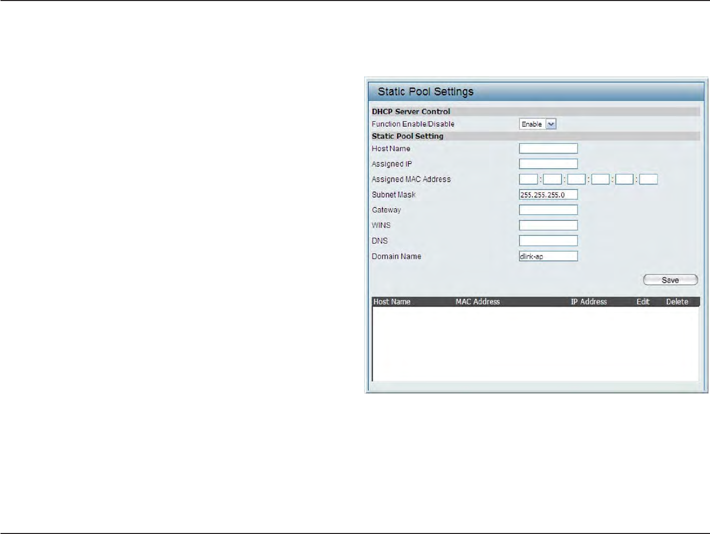
57
D
-
Link
D
A
P
-
2330
U
ser
M
anual
S
e
c
tion
3
-
C
onfigu
r
a
tion
S
ta
tic
Pool
S
etting
The DHCP address
pool
defines
the
range
of
IP addresses
that
can
be
assigned
to
stations
on the
net
w
or
k
.
A static
pool
allows specific
wireless
stations
to
receive a fixed IP
without time
c
on
tr
ol
.
Function Enable/Disable:
Assigned
IP
:
Assigned MAC A
ddr
ess:
Subnet M
ask
:
G
atewa
y
:
WINS:
DNS:
Domain
Name:
Dynamic
Host
C
onfigur
a
tion
P
r
ot
oc
ol
(DHCP)
assigns IP addresses
to
wireless devices
on
the
net
w
or
k
.
This
protocol
simplifies
network
management
and
allows
new
wireless
devices
to
receive IP addresses automatically
w
it
ho
ut
the
need
to
manually assign
IP addresses.
S
elec
t
Enable
to allow the
DAP-2330
to function
as
a
DHCP
ser
v
er
.
U
se
the
S
ta
tic
P
ool
S
ettings
to
assign
the
same
IP
address
to
a device every
time
you
star
t
up
.
T
he
IP addresses assigned
in the
S
ta
tic
Pool list
must
NOT
be in the
same IP
range
as
the Dynamic
P
ool
.
After you
have assigned a static IP
addr
ess
to
a device via
its
MAC address, click
A
pply
;
the
device
will
appear
in the
Assigned
S
ta
tic
Pool
at
the bottom of the
screen. You can
edit or delete
the device
in
this list
.
En
t
er
the
MAC address
of the
device
requesting
association her
e
.
D
efin
e
t
he
su
bn
e
t
m
as
k
o
f
t
h
e
IP
ad
d
r
e
ss
specified
in
the
“IP Assigned
F
rom
”
field
.
Specify the
Ga
t
ew
a
y
address
for
the wireless
net
w
or
k
.
Specify
the
Windows
Internet
Naming
S
ervic
e
(WINS) server address
for the
wireless
net
w
or
k
.
WINS
is a
system
tha
t
determines the
IP address
of
a
network computer
with
a
dynamically assigned
IP address,
if
applicable
.
En
t
er
the DNS server address
for
your wireless
net
w
or
k
.
Specify the domain name
for
the net
w
or
k
.
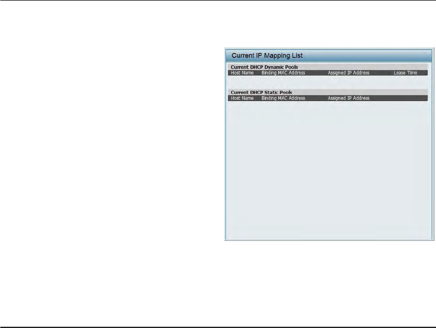
58
D
-
Link
D
A
P
-
2330
U
ser
M
anual
S
e
c
tion
3
-
C
onfigu
r
a
tion
C
urr
en
t
IP
Mapping
List
This
window
displays
information about the
current
assigned DHCP
dynamic and static
IP address
pools
.
This
information
is available when
you
enable DHCP server
on the
AP and assign dynamic and static
IP address
pools
.
C
urr
en
t
DHCP
D
ynamic
P
r
ofile:
Binding
MAC A
ddr
ess:
Assigned IP A
ddr
ess:
Lease
T
ime:
C
urr
en
t
DHCP
S
ta
tic
P
ools:
Binding
MAC A
ddr
ess:
Assigned IP A
ddr
ess:
Binding
MAC A
ddr
ess:
Assigned IP A
ddr
ess:
T
hese
ar
e
IP
addr
ess
pools
the
DHCP
ser
v
er
has
assigned using the dynamic
pool
setting
.
The MAC address
of
a device
on the network
that
is assigned an IP address
from the
DHCP
dynamic pool
.
The
current corresponding
DHCP-assigned
IP
address
of
the
devic
e
.
T
he
length of time
tha
t
the
dynamic
IP
addr
ess
will
be
valid
.
These are
the
IP address
pools of the
DHCP
ser
v
er
assig
ned
thr
ough
the
sta
tic
pool
settings
.
The MAC address
of
a device
on the network
that
is
within
the DHCP static IP address pool
.
The
current
corresponding
DHCP
-assig
ned
static IP address
of
the
devic
e
.
The MAC address
of
a device
on the network
that
is assigned an IP address
from the
DHCP
dynamic pool
.
The
current
corresponding
DHCP
-assig
ned
static IP address
of
the
devic
e
.
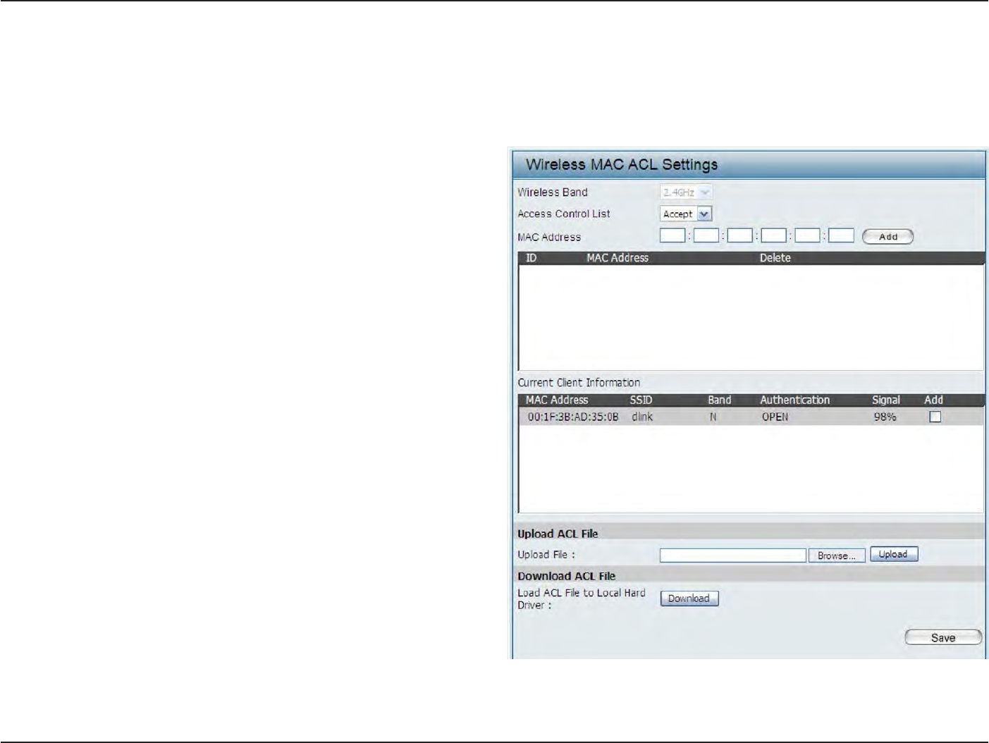
59
D
-
Link
D
A
P
-
2330
U
ser
M
anual
S
e
c
tion
3
-
C
onfigu
r
a
tion
F
ilt
ers
Wireless MAC
A
CL
This page allows
the
user
to
configure
Wireless MAC ACL settings
for
access
c
on
tr
ol
.
Wireless
Band:
Access
C
on
tr
ol
List:
MAC A
ddr
ess:
MAC Address
List:
C
urr
en
t
C
lien
t
I
nf
orma
tion:
Displays
the current
wireless band
r
a
t
e
.
S
elec
t
Disable
to
disable the filters
function.
S
elec
t
A
cce
p
t
t
o
acc
ept
only
those
devic
es
with
M
A
C
addr
esses
in
the
A
cc
ess
C
on
tr
ol
List
.
A
ll
other
devices
not
on the list
will
be
r
ejec
t
ed
.
S
e
lec
t
Reject
to reject the
devices
with
M
A
C
addr
esses
on
the
A
cc
ess
C
on
tr
ol
List
.
A
ll
ot
her
devic
es
not
on the list
will
be
acc
ept
ed
.
En
t
er
each MAC address
that
you wish
to
include
in
your
filter
list
,
and click A
pply
.
W
hen
y
ou
en
t
er
a
M
A
C
addr
ess
,
it
appears
in
this
list
.
Highlight
a
M
A
C
address and click Delete
to remove
it
from this list
.
This table displays
information about all
the current
c
onnec
t
ed
sta
tions
.
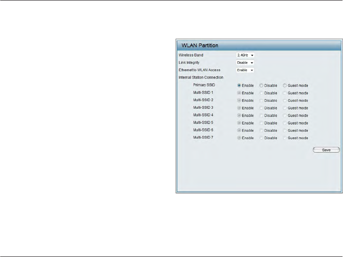
60
D
-
Link
D
A
P
-
2330
U
ser
M
anual
S
e
c
tion
3
-
C
onfigu
r
a
tion
This page allows
the
user
to
configure
a WLAN
P
ar
tition.
WLAN
P
ar
tition
Wireless
Band:
Link
I
n
t
eg
rit
y
:
E
thernet
WLAN A
cc
ess:
Internal
S
ta
tion
C
onnec
tion:
Displays
the
current
wireless
band
.
S
el
ec
t
Enable
or
D
isable
.
If the
E
thernet
connection
between the
LAN
and the
AP
is
disconnec
t
ed
,
enabling
this
feature
will cause
the wireless seg
men
t
associa
t
ed
with
the AP
t
o
be
disassocia
t
ed
fr
om
the
A
P
.
The
default is
Enable
.
When disabled
,
all data
fr
om
the
E
thernet
t
o
associa
t
ed
wir
eless
devices
will be
blocked
.
Wireless devices can
still send
da
ta
to
the
E
thernet
.
T
he
default
v
alue
is
Enable
,
which
allo
w
s
stations
to
intercommunicate by connecting
to
a
target
AP. When
disabled
,
wireless stations
cannot
e
xchange
da
ta
on
the
same
M
ulti-SSID
.
I
n
Guest
mode
,
wireless stations cannot exchange
data
with
any
station on
your net
w
or
k
.
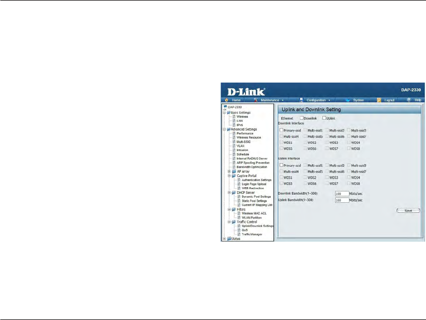
61
D
-
Link
D
A
P
-
2330
U
ser
M
anual
S
e
c
tion
3
-
C
onfigu
r
a
tion
Traffic
C
on
tr
ol
Uplink/Downlink
S
etting
The
uplink/downlink
setting allows users
to
customize
the downlink
and
uplink
in
t
erfac
es
including
specifying
downlink/uplink bandwidth rates
in
Mbits per
sec
ond
.
These values are also used
in the
QoS and Traffic Manager windo
w
s
.
Once
the
desired
uplink
and
downlink
settings
are
finished
,
click
the
Save
button to let
your changes take
eff
ec
t
.
Downlink Bandwidth:
Uplink Bandwidth:
The
downlink bandwidth in
Mbits per
sec
ond
.
Uplink
Bandwidth: The
uplink bandwidth
in
Mbits per
sec
ond
.
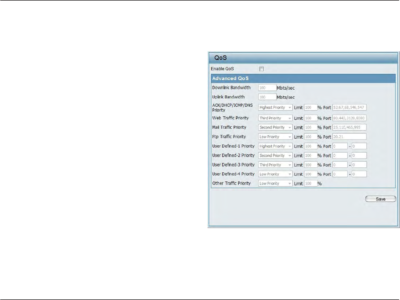
62
D
-
Link
D
A
P
-
2330
U
ser
M
anual
S
e
c
tion
3
-
C
onfigu
r
a
tion
QoS
Quality
of
S
ervic
e
(QoS) enhances
the
experience
of
using a network
by prioritizing the
traffic
of different
applica
tions
.
The DAP-2330
supports
four priority
lev
els
.
Once
the
desired QoS settings are
finished
,
click
the
Save
button to let
your changes take
eff
ec
t
.
Enable
QoS:
Downlink Bandwidth:
Uplink Bandwidth:
Check this box
to
allow QoS
to
prioritize
tr
affic
.
Use
the drop-down
menus
to
selec
t
the four
levels
of pr
ior
it
y
.
Click
the
Save
button when
you are
finished
.
D
o
w
n
li
n
k
B
a
n
dw
i
d
t
h
:
T
h
e
d
o
w
n
li
n
k
b
an
dw
i
d
t
h
in
Mbits per
sec
ond
.
T
his
v
alue
is
en
t
ered
in
the
Uplink/Downlink
S
etting
windo
w
.
Uplink
Bandwidth: The
uplink bandwidth
in
Mbits per
sec
ond
.
This value
is
en
t
ered
in the
Uplink/Downlink
S
etting
windo
w
.
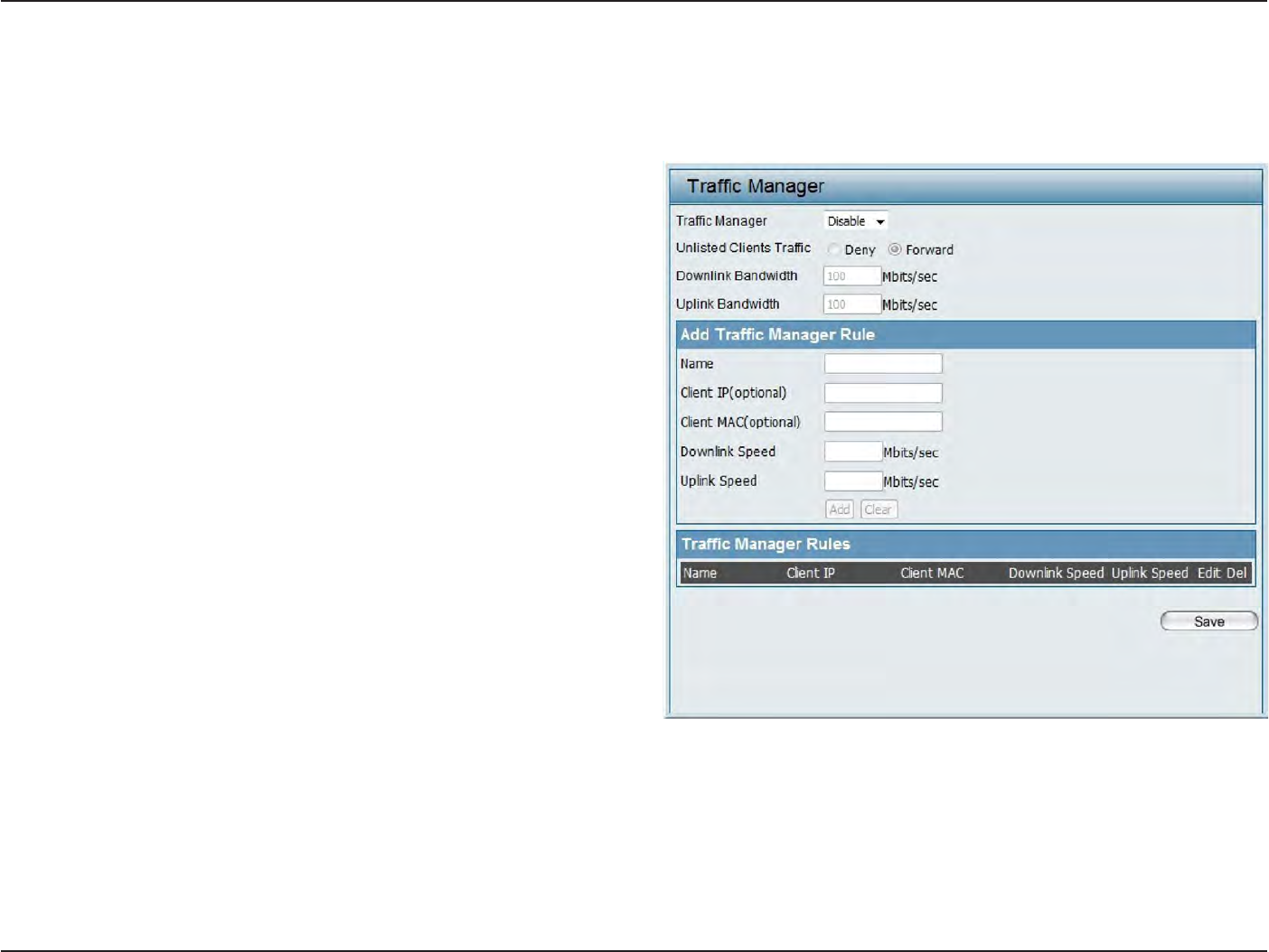
63
D
-
Link
D
A
P
-
2330
U
ser
M
anual
S
e
c
tion
3
-
C
onfigu
r
a
tion
Traffic
Manager
The traffic manager feature allows users
to
cr
ea
t
e
traffic management
rules
that
specify
how to
deal
with
listed
client
traffic and
specify
downlink/ uplink
speed
for
new traffic manager rules
.
Click
the
Save
button to let
your changes take
eff
ec
t
.
Traffic
Manager:
Unlisted
C
lien
t
Traffic:
Downlink Bandwidth:
Uplink Bandwidth:
Use
the drop-down menu
to
Enable the
traffic
manager
f
ea
tur
e
.
S
elec
t
Deny or
Forward
to
determine
how
t
o
deal
with
unlisted client
tr
affic
.
The
downlink bandwidth in
Mbits per
sec
ond
.
This value
is
entered
in the Uplink/Downlink
S
etting
windo
w
.
Uplink
B
a
n
dw
i
d
t
h
:
T
h
e
uplink bandwidth
i
n
Mbits per
sec
ond
.
This value
is
en
t
ered
in the
Uplink/Downlink
S
etting
windo
w
.
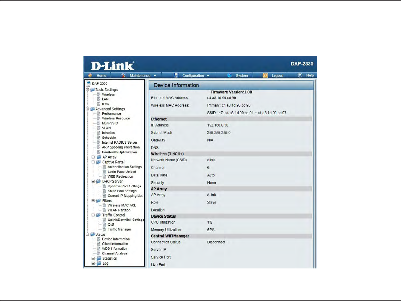
64
D
-
Link
D
A
P
-
2330
U
ser
M
anual
S
e
c
tion
3
-
C
onfigu
r
a
tion
S
ta
tus
In
the
S
ta
tus
S
ec
tion
the
user can
monitor
and view configuration settings
of the
access poin
t
.
Here
the
user can also view statistics
about client
information,
WDS
information
and
mor
e
.
The
following
pages
will
explain settings
found in the
S
ta
tus
section
in
more detail
.
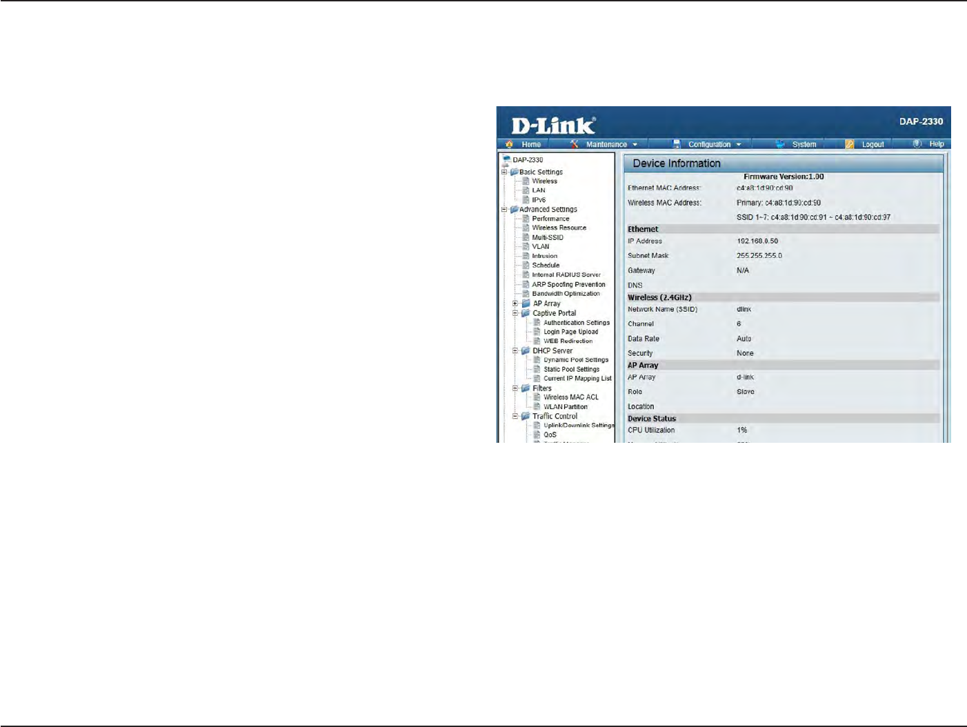
65
D
-
Link
D
A
P
-
2330
U
ser
M
anual
S
e
c
tion
3
-
C
onfigu
r
a
tion
Device I
nf
orma
tion
This page displays
the
current
information
like firmware version,
E
thernet
and wireless par
amet
ers
,
as
well
as
the information
regarding
CPU
and
memory
utilization.
Device
Information:
This
r
ead-
only window
displays
the
configuration
s
e
tt
i
n
g
s
of the
DA
P
-2330
,
including the firmware
version
and the
device’s MAC
addr
ess
.
66
D
-
Link
D
A
P
-
2330
U
ser
M
anual
S
e
c
tion
3
-
C
onfigu
r
a
tion
C
lien
t
I
nf
orma
tion
This page displays
the
associa
t
ed
clients
SSID, MAC,
band
,
authentication method
,
signal strength, and power saving mode
for the DAP-2330
net
w
or
k
.
C
lien
t
I
nf
orma
tion:
SSID:
M
AC
:
B
and:
A
uthen
tica
tion:
RSSI:
Power
S
a
ving
Mode:
This
window
displays
the
wireless
client
information for
clients currently
connected
to
the
DAP-2330.
Displays the
SSID
of
the clien
t
.
Displays the MAC address
of
the clien
t
.
Displays
the
wireless band
that the client is
c
onnec
t
ed
t
o
.
Displays
the type of authentication being
used
.
Displays the
clien
t
’
s
signal
strength.
Displays
the
status
of the power
sa
ving
f
ea
tur
e
.
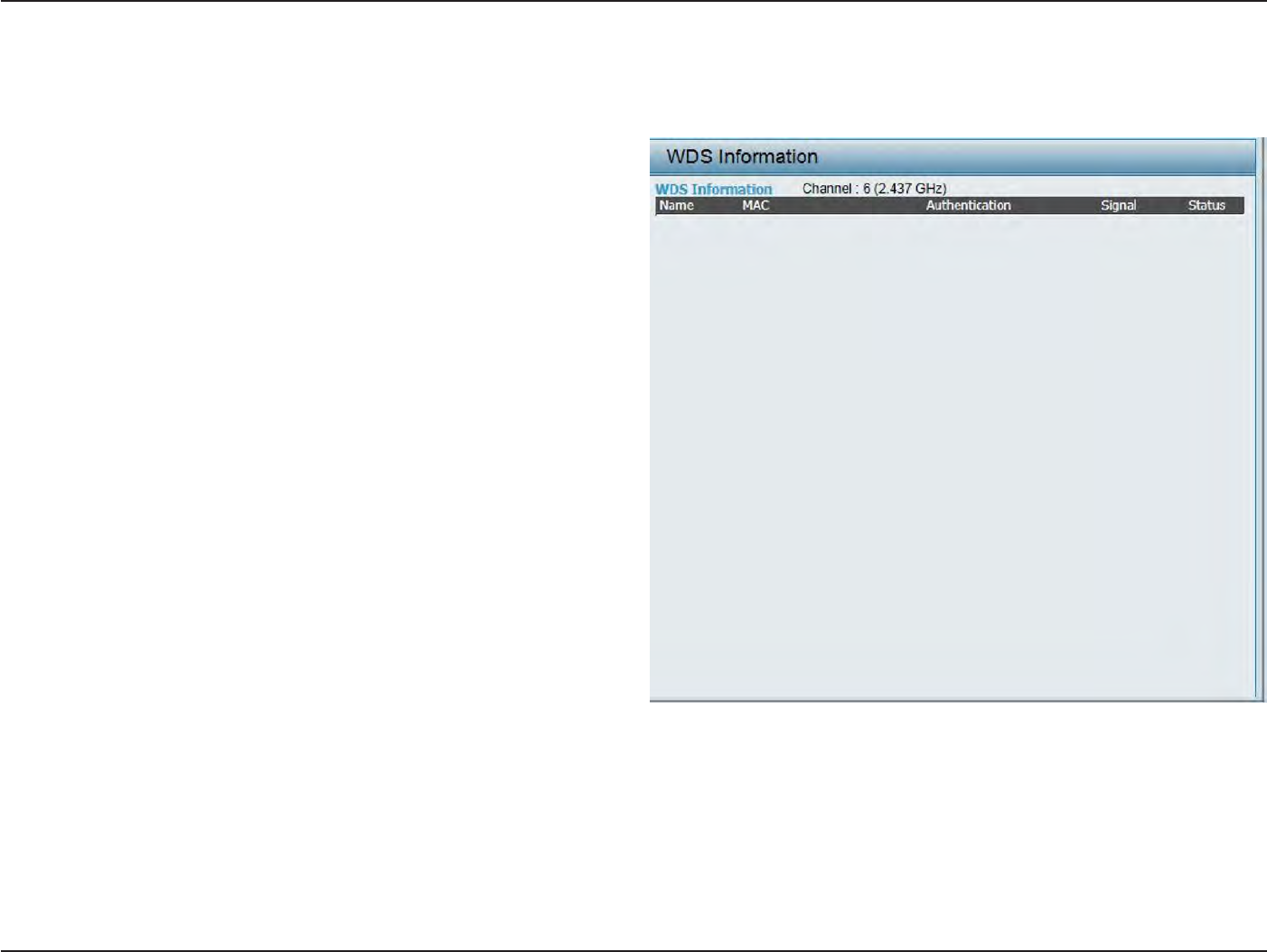
67
D
-
Link
D
A
P
-
2330
U
ser
M
anual
S
e
c
tion
3
-
C
onfigu
r
a
tion
WDS
Information
P
age
This page displays
the
access points
SSID, MAC,
band
,
authentication method
,
signal strength, and status
for the
DAP-2330’s Wireless
Distr
ibution
S
yst
em
net
w
or
k
.
WDS
I
nf
orma
tion:
Name:
M
AC
:
A
uthen
tica
tion:
Sig
nal:
S
ta
tus:
T
hi
s
wi
nd
o
wd
is
p
lay
s
t
he
W
ir
e
le
ss
D
is
tri
bu
t
io
n
S
yst
em
information for clients currently
c
onnec
t
ed
to
the
DAP-2330.
Displays the
SSID
of
the clien
t
.
Displays the MAC address
of
the clien
t
.
Displays
the type of authentication being
used
.
Displays the
clien
t
’
s
signal
strength.
Displays
the
status
of the power
sa
ving
f
ea
tur
e
.
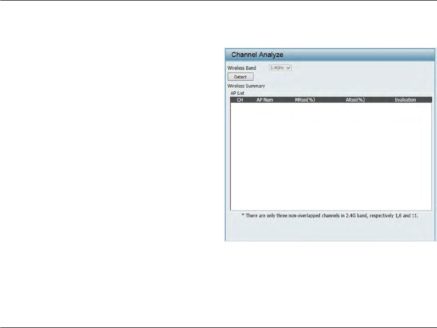
68
D
-
Link
D
A
P
-
2330
U
ser
M
anual
S
e
c
tion
3
-
C
onfigu
r
a
tion
Channel A
nalyz
e
Wireless
Band:
Detect:
AP
List:
S
elec
t
2.4GHz
in
default
.
Click the
D
et
ec
t
button to scan.
This
will list the transmitting
channels
and
qualit
y
.
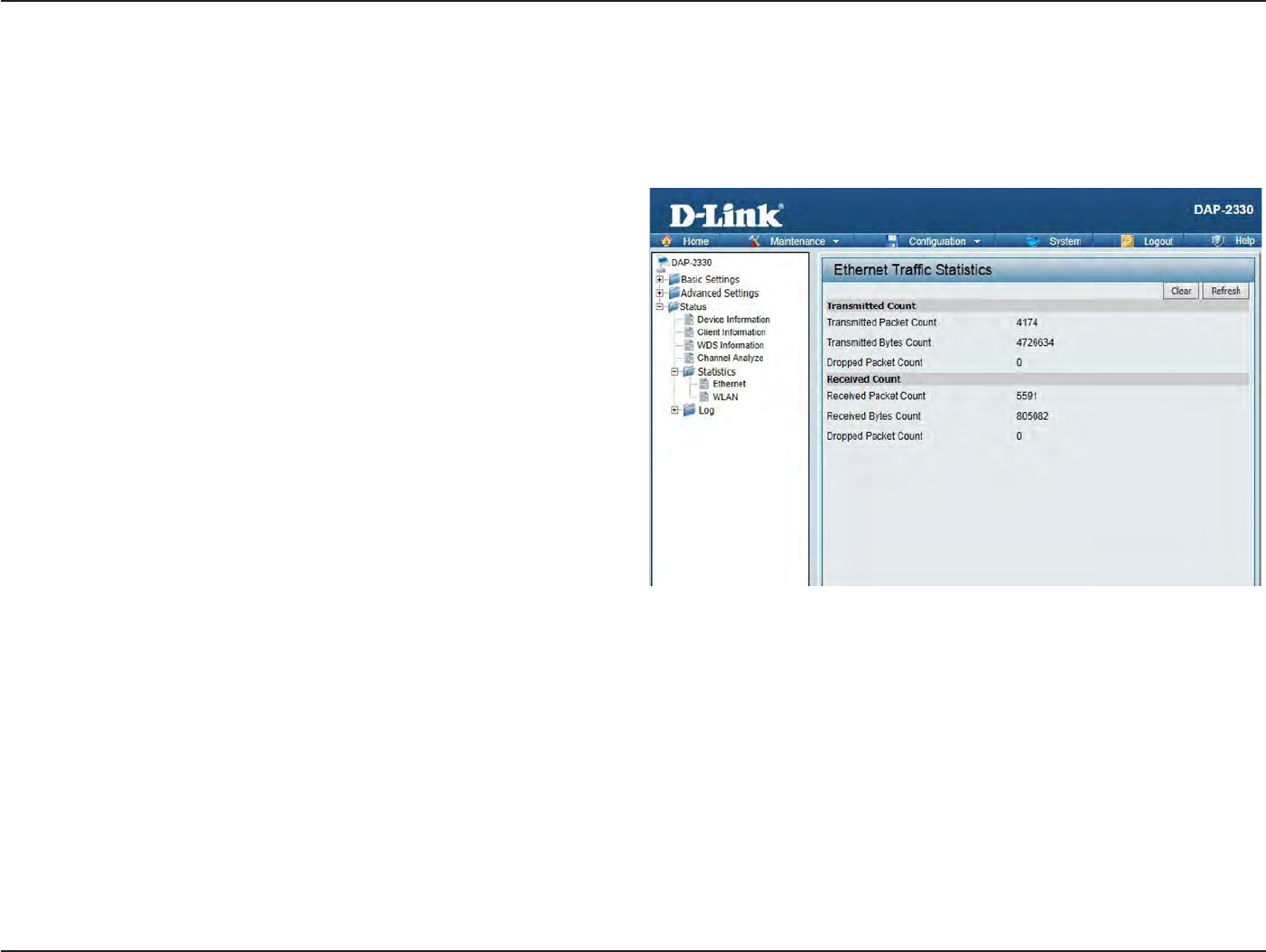
69
D
-
Link
D
A
P
-
2330
U
ser
M
anual
S
e
c
tion
3
-
C
onfigu
r
a
tion
Displays
wired
in
t
erfac
e
network traffic
information.
S
ta
ts
P
age
E
thernet
Traffic
S
ta
tistics
E
thernet
Traffic
S
ta
tistics:
T
his
page
display
s
tr
ansmitt
ed
and
received
count
statistics
for
packets and
byt
es
.
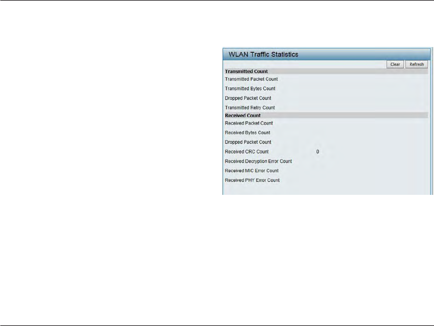
70
D
-
Link
D
A
P
-
2330
U
ser
M
anual
S
e
c
tion
3
-
C
onfigu
r
a
tion
WLAN Traffic
S
ta
tistics
Displays
throughput
,
transmitted
fr
ame
,
received
fr
ame
,
and WEP frame error
information for the
AP
net
w
or
k
.
WLAN Traffic
S
ta
tistics:
This page displays wireless
network
statistics
for
data
throughput
,
transmitted and received
fr
ames
,
and
frame er
r
ors
.
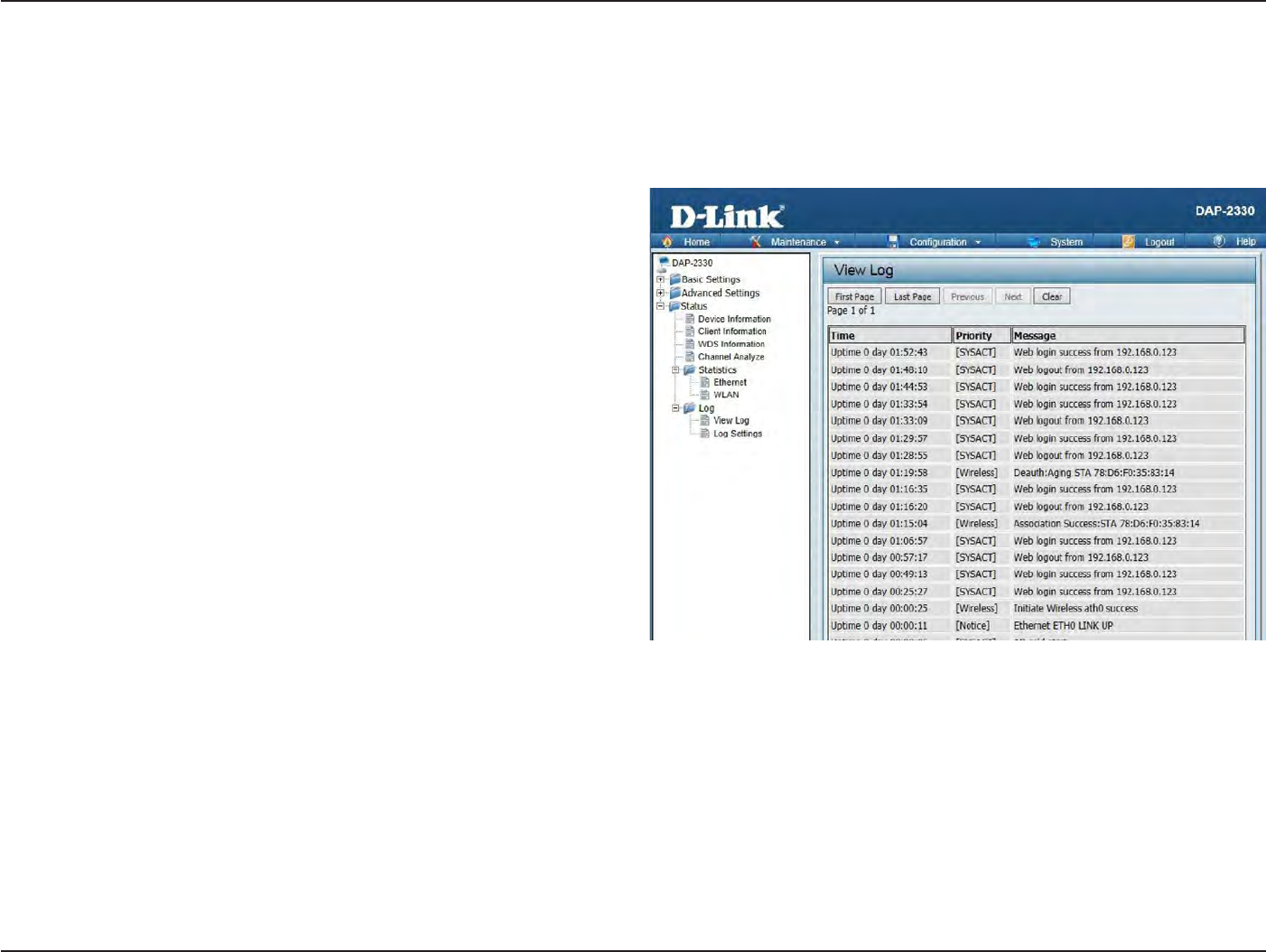
71
D
-
Link
D
A
P
-
2330
U
ser
M
anual
S
e
c
tion
3
-
C
onfigu
r
a
tion
Lo
g
View
L
og
The AP’s
embedded memory holds logs her
e
.
The
log information
includes
but
is
not limited to the following
items:
cold
star
t
AP,
upgrading
fir
m
w
ar
e
,
client
associa
t
e
and
disassocia
t
e
with
AP, and
web
login. The
web
page holds
up to
500 logs
.
View
Log:
The AP’s
embedded memory
display
s
system and network messages
including
a
time
stamp and message
t
ype
.
The
log
information
includes
but
is
not
limit
ed
to the following
items:
cold
star
t
A
P
,
upgrading
fir
m
w
ar
e
,
client
associa
t
e
and
disassocia
t
e
with
AP, and
web
login.
T
he
web
page holds
up to
500 logs
.
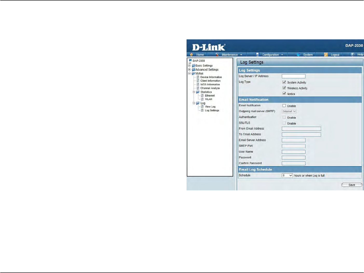
72
D
-
Link
D
A
P
-
2330
U
ser
M
anual
S
e
c
tion
3
-
C
onfigu
r
a
tion
Log
S
ettings
En
t
er
the log
server’s IP address
to
send
the log to that
ser
v
er
.
Check
or
uncheck
S
yst
em
A
c
tivit
y
,
Wireless
A
c
tivit
y
,
or
Notice
to
specify
what kind
of log type
you
want it to log
.
Log
S
er
v
er/IP
A
ddr
ess:
Log
T
ype:
E-mail Notifica
tion:
E-mail Log
S
chedule:
En
t
er
the
IP address
of the
server
you
would
like
to
send
the
DAP-2330
log
t
o
.
Check
the box for the type of activity
you
want to log
.
There are three
types:
S
yst
em
A
c
tivit
y
,
Wireless
A
c
tivit
y
,
and
Notic
e
.
Support
Simple Mail Transfer
P
r
ot
oc
ol for
log
schedule and periodical change key
.
I
t
can
not
support
Gmail SMTP
port 465.
Please set
to
Gmail SMTP
port
25
or 587.
Use
the drop-down
menu
to
set
the
e-mail
log
schedule
.
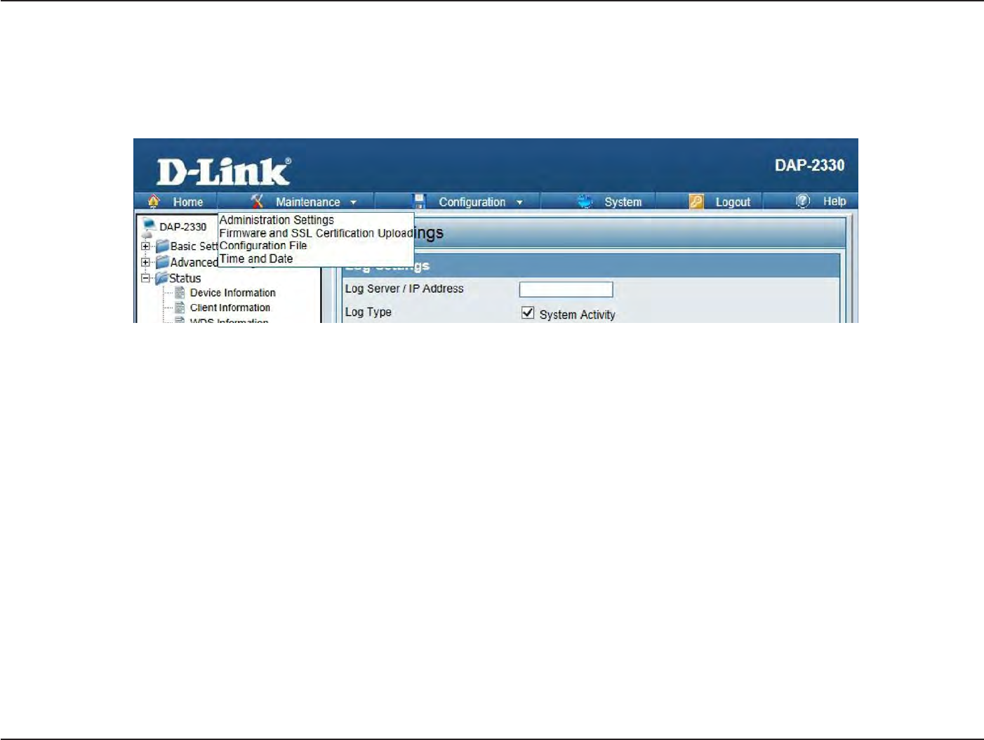
73
D
-
Link
D
A
P
-
2330
U
ser
M
anual
S
e
c
tion
3
-
C
onfigu
r
a
tion
M
ain
t
enanc
e
S
ec
tion
In
the
S
ta
tus
S
ec
tion
the
user can
monitor
and view configuration settings
of the
access poin
t
.
Here
the
user can also view statistics
about client
information,
WDS
information
and
mor
e
.
The
following
pages
will
explain settings
found in the
main
t
enanc
e
section
in
more detail
.
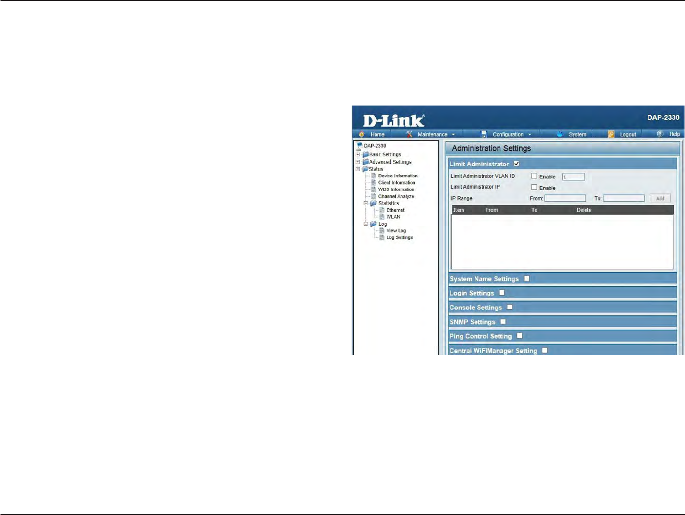
74
D
-
Link
D
A
P
-
2330
U
ser
M
anual
S
e
c
tion
3
-
C
onfigu
r
a
tion
A
dministr
a
tion
Limit
A
dministr
a
t
or
Check one
or
more
of the
five main
ca
t
egor
ies
to
display
the
various
hidden
administrator
parameters and settings displayed
on the
next
five
pages
.
Each
of the
five main
ca
t
egor
ies
display various
hidden
administrator
parameters and settings
.
Limit
Administrator
VL
AN
ID:
Limit
Administrator
IP
:
IP
R
ange:
Check
the box
provided and
the enter
the
specific VLAN ID
that the
administrator
will be
allowed
to log
in
from.
Check
to
enable
the Limit Administrator
IP
addr
ess
.
En
t
er
the
IP address range
that the
administrator
will be
allowed
to log
in
from
and
then
click
the
Add
butt
on.
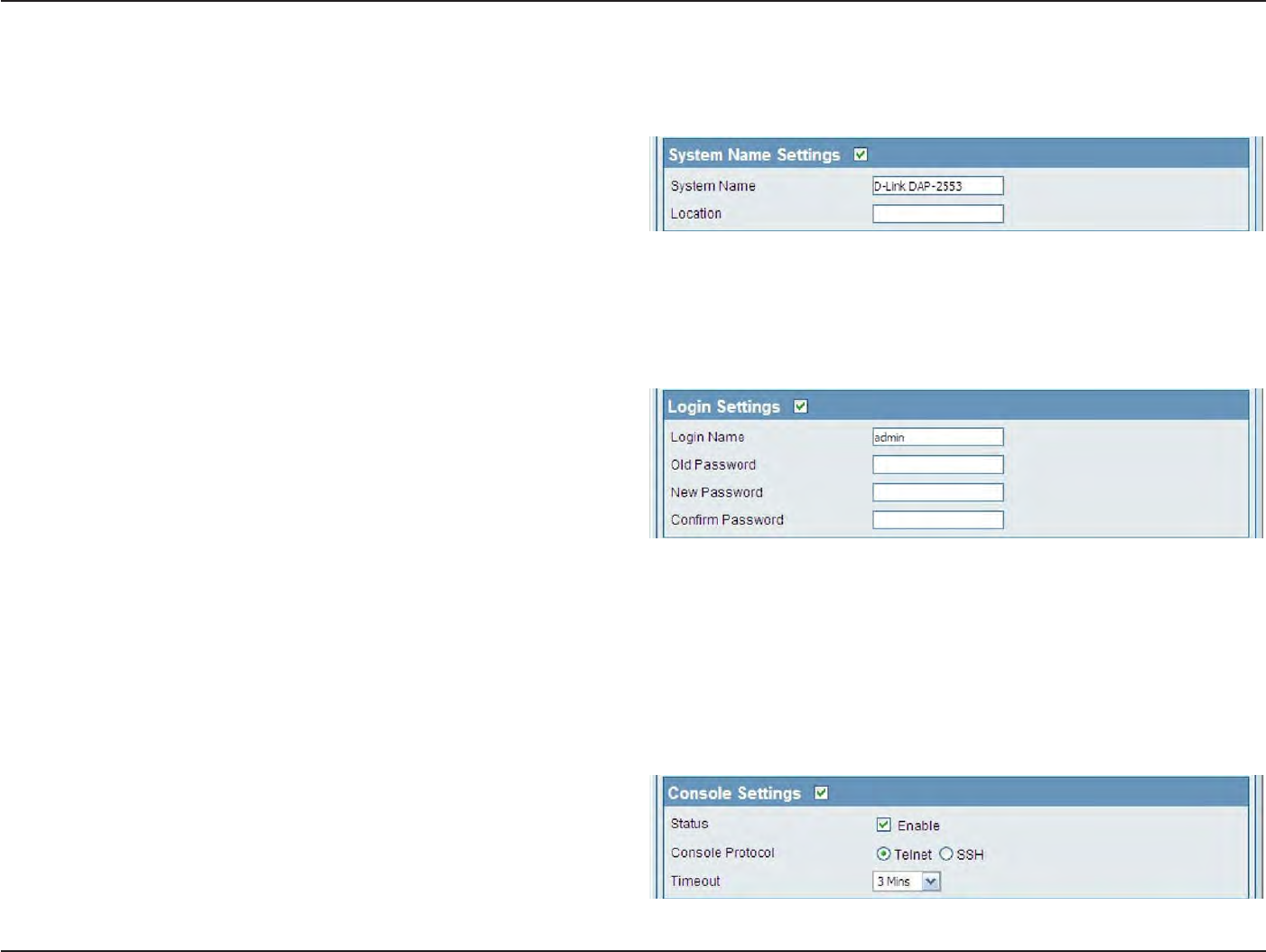
75
D
-
Link
D
A
P
-
2330
U
ser
M
anual
S
e
c
tion
3
-
C
onfigu
r
a
tion
S
y
stem
Name
S
ettings
Each
of the
five main
ca
t
egor
ies
display various
hidden
administrator
parameters and settings
.
S
y
stem
Name:
L
oca
tion:
The name
of the
devic
e
.
The
default
name is D-Link
DAP-2330.
The physical location
of the
devic
e
,
e
.g
.
72nd
F
loor
,
D-Link
HQ
.
Login
S
ettings
Each
of the
five main
ca
t
egor
ies
display various
hidden
administrator
parameters and settings
.
User
Name:
Old
P
assw
or
d:
New
P
assw
or
d:
C
onfirm
P
assw
or
d:
En
t
er
a user
name
.
The default is
admin.
When changing your passw
or
d
,
enter
the
old
password her
e
.
When changing your passw
or
d
,
enter
the
new password her
e
.
The password is
case
-sensitiv
e
.
“
A
”
is a
different
char
ac
t
er
than
“
a
.
”
The
length
should
be
between
0
and 12 char
ac
t
ers
.
En
t
er
the
new password a second
time for
confirmation pur
poses
.
Console
S
ettings
Each
of the
five main
ca
t
egor
ies
display various
hidden
administrator
parameters and settings
.
S
ta
tus:
Console
P
rot
oc
ol:
Time-out:
S
ta
tus
is enabled
by
default
.
Uncheck
the
box to
disable
the
c
onsole
.
S
elec
t
the type of protocol
you
w
ould
like
to
use, Telnet
or
SSH.
Set
to 1
Min,
3
M
ins
,
5
M
ins
,
10
M
ins
,
15 Mins
or
Never
.
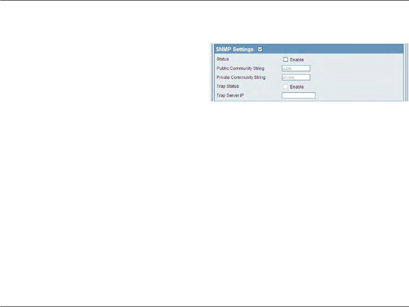
76
D
-
Link
D
A
P
-
2330
U
ser
M
anual
S
e
c
tion
3
-
C
onfigu
r
a
tion
SNMP
S
ettings
Each
of the
five main
ca
t
egor
ies
display various
hidden
administrator
parameters and settings
.
S
ta
tus:
Public
C
ommunit
y
S
tring:
P
riv
a
t
e
C
ommunit
y
S
tring:
Check
the box to
enable
the SNMP
functions
.
This is enabled
by
default
.
En
t
er
the public
SNMP
community
str
ing
.
En
t
er
the
private
SNMP
community
str
ing
.

77
D
-
Link
D
A
P
-
2330
U
ser
M
anual
S
e
c
tion
3
-
C
onfigu
r
a
tion
A
dministr
a
tion
Central WiFiManager
S
ettings
The Central WiFiManager section is used
to
cr
ea
t
e
a set
of
APs
on the
Internet
to be
organized
into
a single
group in
order
to
increase ease
of
managemen
t
.
Central WiFiManager and AP Array are
mutually
exclusive
functions
.
Enable
C
en
tr
al
WiF
iM
anager:
S
elec
t
to
enable
or
disable
the
C
en
tr
al
W
iF
iM
anager
.
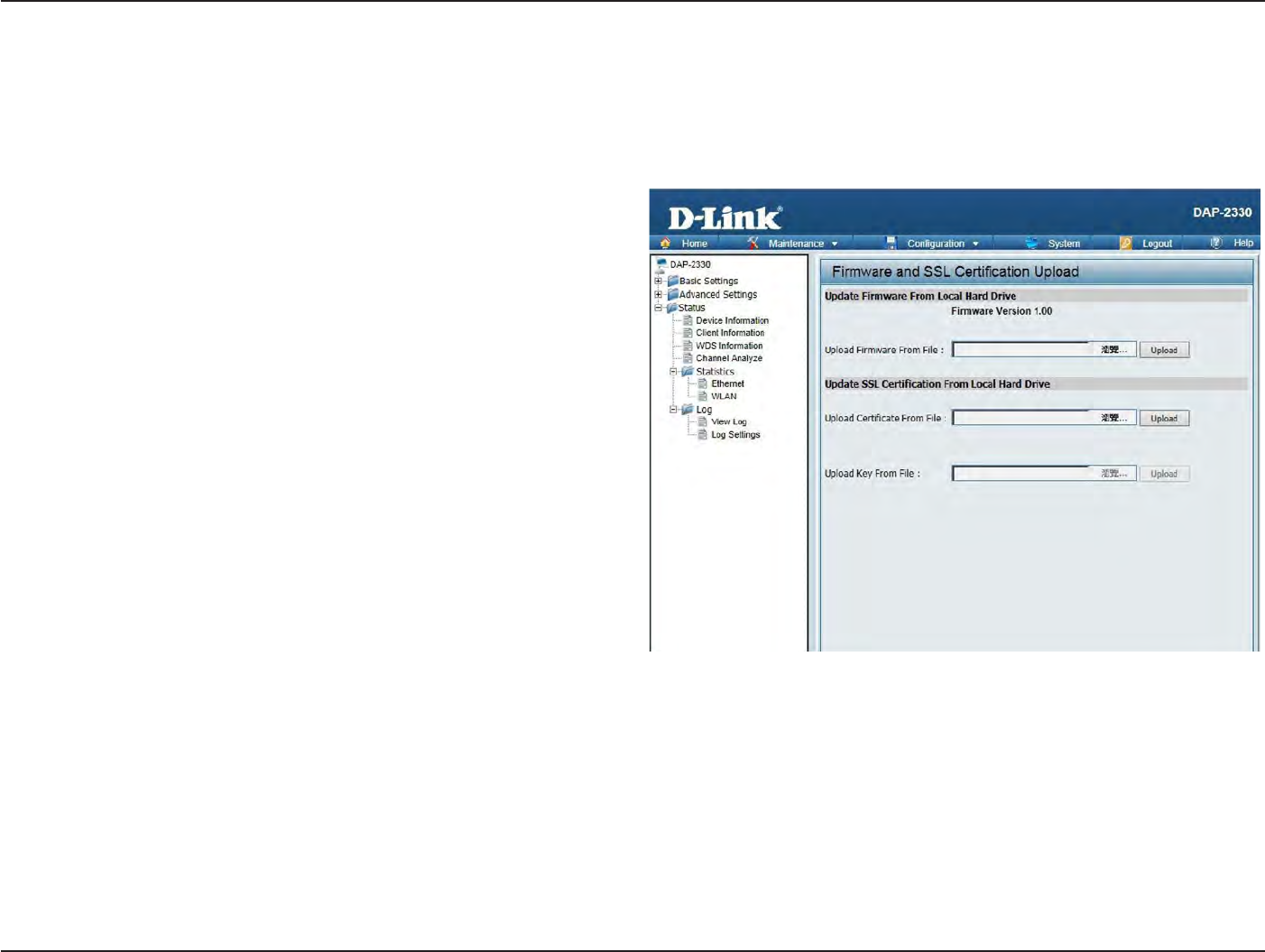
78
D
-
Link
D
A
P
-
2330
U
ser
M
anual
S
e
c
tion
3
-
C
onfigu
r
a
tion
Firmware
and
SSL
Upload
This page allows
the
user
to
perform a firmware upg
r
ade
.
A Firmware upgrade is a
function that
upgrade
the running
sof
t
w
ar
e
used
by the
access poin
t
.
This is a useful feature
that
prevents
future
bugs and allows
for
new features
to be
added
to
this produc
t
.
Please
go to
your
local
D-Link website
to
see
if
there is a newer version firmware
a
v
ailable
.
Firmware
and
SSL
C
er
tifica
tion
Upload:
Upload
Firmware
fr
om
Local Hard
Drive:
Upload
SSL C
er
tifica
tion
from
Local Hard
Drive:
You can upload files
to the
access poin
t
.
The
current firmware
version is
displayed
above
the file
location field
.
After
the
la
t
est
firmware is do
wnloaded
,
click
on
the
“Choose
F
ile
”
button to
loca
t
e
the
new
fir
m
w
ar
e
.
Once
the file
is selec
t
ed
,
click
on
the
“
Open
”
and
“Upload
”
butt
on
to begin updating the
fir
m
w
ar
e
.
P
lease
don’t turn the
power
off while upg
rading
.
After you
have downloaded a SSL
certification
to
your local dr
iv
e
,
click
“Choose
F
ile
.
”
S
elec
t
the
certification
and
click
“
Open
”
and
“Upload
”
to complete
the upg
r
ade
.
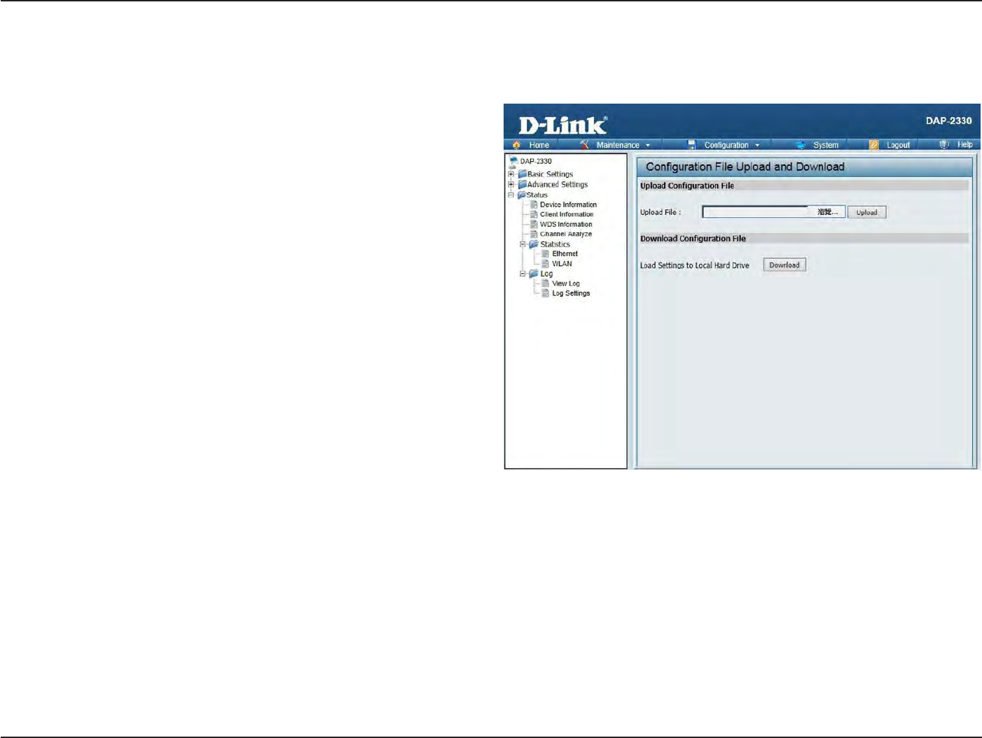
79
D
-
Link
D
A
P
-
2330
U
ser
M
anual
S
e
c
tion
3
-
C
onfigu
r
a
tion
C
onfigur
a
tion
File
Upload
This page allows
the
user
to
backup and recover
the
current configuration
of the
access
point in
case
of
a
unit
failur
e
.
C
onfigur
a
tion
File
Upload
and
Do
wnload:
Upload
C
onfigur
a
tion
F
ile:
Download
C
onfigur
a
tion
F
ile:
You can upload and
download
configuration files
of the
access poin
t
.
Browse
to the
saved
configuration
file
you have
in
local drive and
click
“
Open
”
and
“Upload
”
to
update
the
configuration.
Click
“Download
”
to
save
the current
configuration
file to
your local disk
.
Note
that if
you save
one configuration
file
with the
administr
a
t
or
’
s
password
no
w
,
after resetting your
DAP-2330 and
then
updating to
this saved
configuration file
,
the
password
will be
gone
.
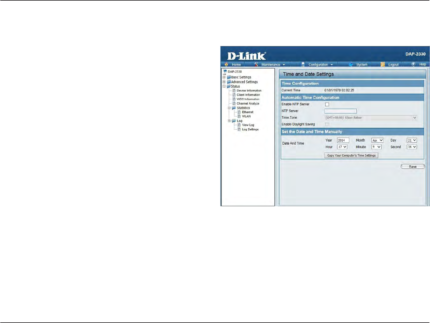
80
D
-
Link
D
A
P
-
2330
U
ser
M
anual
S
e
c
tion
3
-
C
onfigu
r
a
tion
Time
and
Da
t
e
S
ettings
En
t
er
the
NTP server IP,
choose
the time
z
one
,
and enable
or
disable
daylight
saving time
.
C
urr
en
t
T
ime:
Enable NTP
S
er
v
er:
NTP
S
er
v
er:
Time Z
one:
Enable Da
yligh
t
S
a
ving:
Daylight
S
a
ving
Da
t
es:
Set
the
Da
t
e
and
Time
M
anually
:
Displays
the current
time
and
date
settings
.
Check
to
enable
the
AP
to get
system
time
from an NTP server from the I
n
t
er
net
.
En
t
er
the NTP server IP
addr
ess
.
Use
the drop-down menu to
selec
t
your
c
orr
ec
t
Time
Z
one
.
Check
the box to
enable
Daylight
S
a
ving
Ti
m
e.
Use
the drop-down menu to
selec
t
the
c
orr
ec
t
Daylight
S
a
ving
off
set
.
A
user
can either
manually
set the
t
ime
for the
AP
her
e
,
or click the
Copy
Y
our
Computer’s Time
S
ettings
button to copy
the time from the computer in
use
(Make
sur
e
tha
t
the
c
omput
er’
s
time
is
set
correctly).
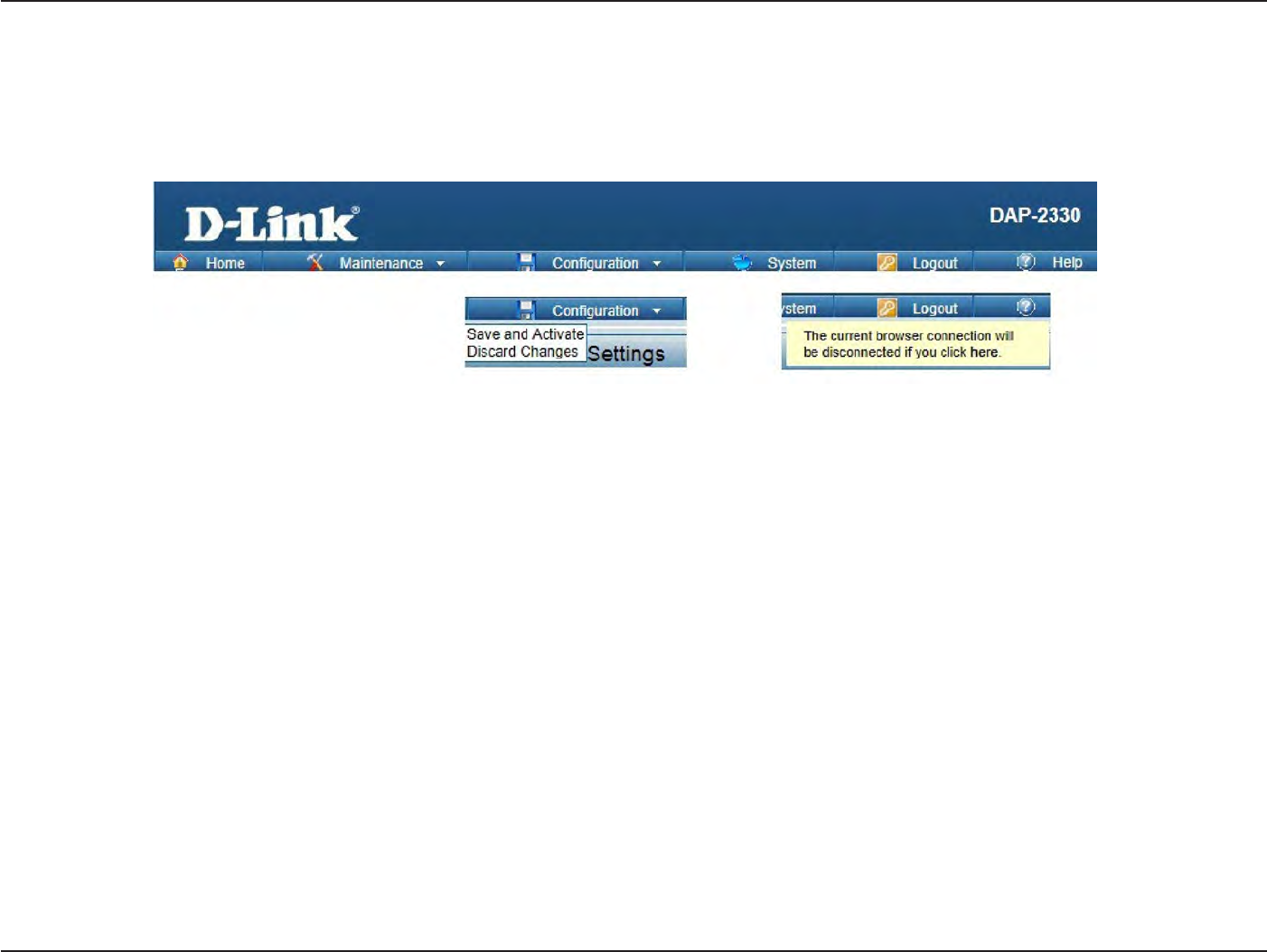
81
D
-
Link
D
A
P
-
2330
U
ser
M
anual
S
e
c
tion
3
-
C
onfigu
r
a
tion
C
onfigur
a
tion
and
S
y
stem
These options are
the
remaining
option to
choose
from in the top
menu
.
C
onfigur
a
tion
allows
the
user
to
save and ac
tiv
a
t
e
or
discard
the
configurations done
.
S
yst
em
allows
the
user
to
r
estar
t
the
unit
,
perform a
factory
reset or
clear
the
language pack settings
.
Logout allows
the
user
to
safely
log out from the
access poin
t
’
s
web
configuration. Help allows
the
user
to
read more
about the
given options
to
configure
without
the
need
to
consult
the
manual
.
The
following
pages
will
explain settings
found in the
configuration and system section
in
more detail
.
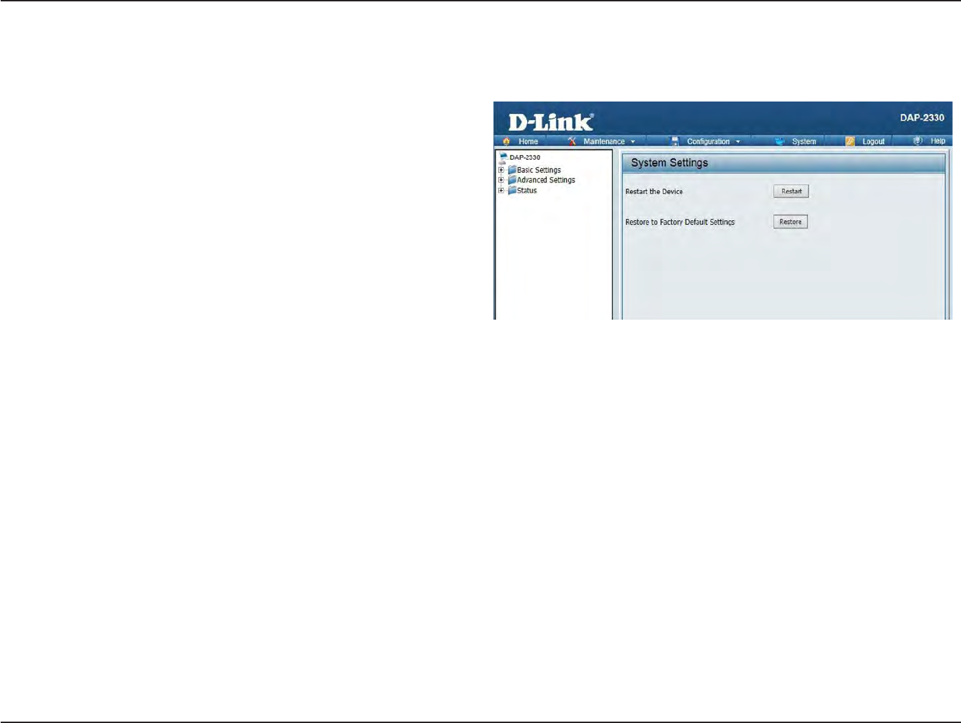
82
D
-
Link
D
A
P
-
2330
U
ser
M
anual
S
e
c
tion
3
-
C
onfigu
r
a
tion
S
y
stem
S
ettings
On this page
the
user can
r
estar
t
the
unit
,
perform a
factory
reset
of the
access
point or
clear
the
added language pack
.
R
estar
t
the Device:
Restore
to
F
ac
t
or
y
Default
S
ettings:
Clear Language
P
ack
:
Click
R
estar
t
to
r
estar
t
the DAP-2330.
Click
R
est
or
e
to
restore
the
D
AP
-2330
back
to
factory default
settings
.
Click
to
clear
the
current
Language
pack
running
.
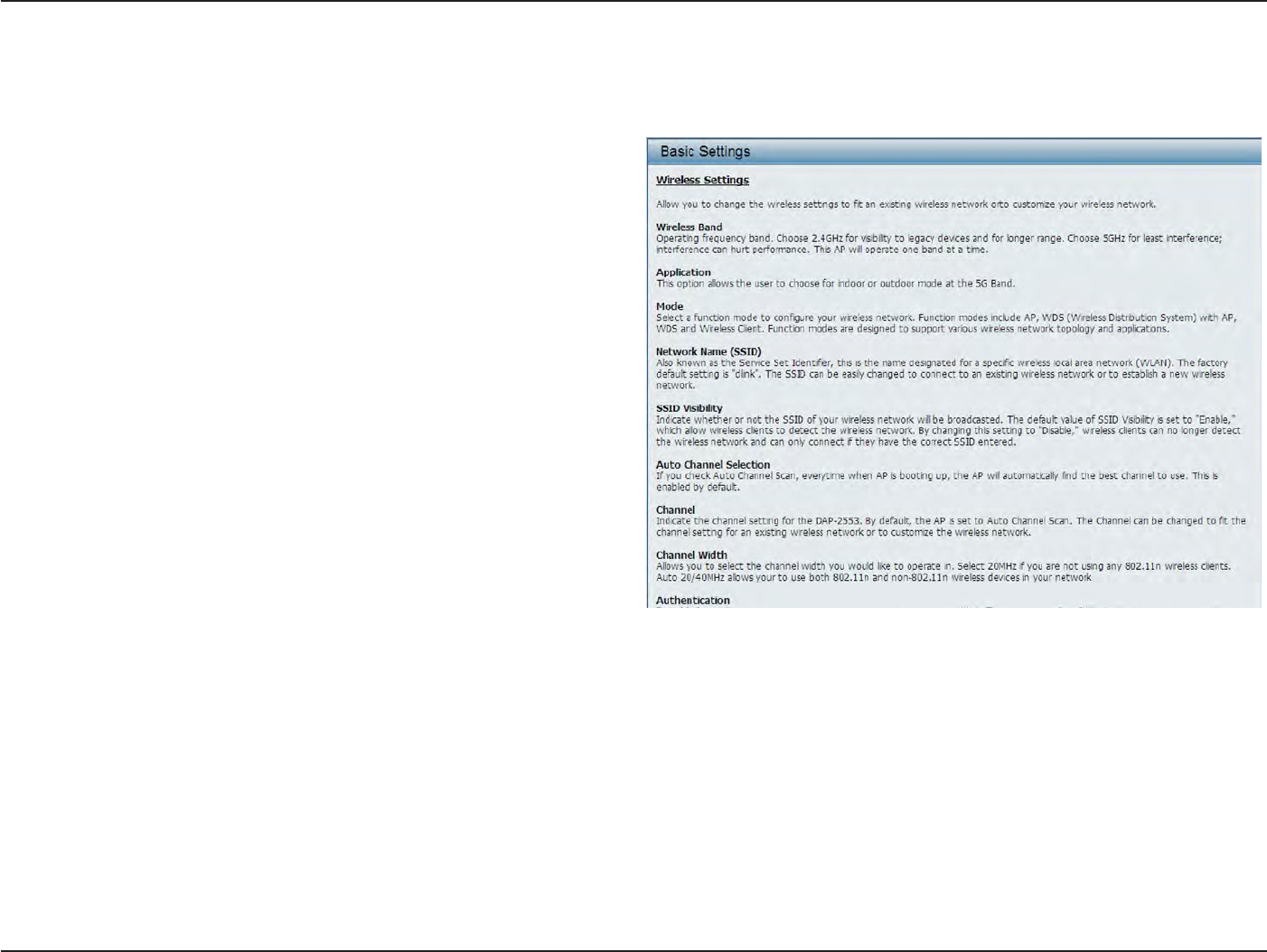
83
D
-
Link
D
A
P
-
2330
U
ser
M
anual
S
e
c
tion
3
-
C
onfigu
r
a
tion
Help
The
help
page is useful
to
view a
brief
description
of
a
function
available
on the
access
point in
case
the
manual is
not pr
esen
t
.
Help:
S
cr
oll
down the
Help page
for
topics
and
e
xplana
tions
.

84
D
-
Link
D
A
P
-
2330
U
ser
M
anual
A
ppendix
A
-
W
i
r
eless
Basics
Knowledge
B
ase
Wireless
B
asics
D-Link wireless products are based
on
industry standards
to
provide high-speed wireless connectivity
that
is easy
to
use
within
your home
,
business
or public
access wireless
net
w
or
ks
.
D-Link wireless products provides you
with
access
to the
data you
w
an
t
,
whenever and
wherever
you
want
it
.
Enjoy
the
freedom
that
wireless networking can
bring to
y
ou
.
WLAN use is
not only
increasing
in both
home and office
en
vironmen
ts
,
but in public
areas as
w
ell
,
such as
air
por
ts
,
coffee shops and
univ
ersities
.
Innovative ways
to
utilize WLAN
technology
are
allowing
people
to
work and communicate more efficien
tly
.
Increased
mobility
and
the absence
of
cabling and
other
t
ypes
of
fixed infrastructure have proven
to be
beneficial
to
many
users
.
Wireless adapter cards used
on laptop
and desktop systems
support
the
same protocols
as
E
thernet
adapter cards,
allowing
wireless users
to use
the
same applications
as those used
on
a
wired
net
w
or
k
.
People use WLAN
technology
for
many
different purposes:
• Mobility - productivity
increases when people can have access
to
data
in
any location
within the
operating range
of their WLAN.
M
anagemen
t
decisions based
on
real-time
information
can significantly improve
the
efficiency
of
a
w
or
ker
.
• Low implementation
costs - WLANs are easy
to
set up
,
manage
,
change and
r
eloca
t
e
.
Networks
that
frequently change can
benefit from
WLAN’s ease
of
implementation.
WLANs can
oper
a
t
e
in
locations where installation
of wiring
may
be
impr
ac
tical
.
• Installation and network
expansion
- by
avoiding
the
complications
of
troublesome
cables
,
a WLAN system can
be
fast and easy
during
installation, especially since
it
can
eliminate
the
need
to pull
cable
through
walls and
c
eilings
.
Wireless
technology provides more
versatility
by
extending
the
network beyond
the
home
or
offic
e
.
•
Inexpensive
solution -
wireless network devices are
as
competitively priced
as
conventional
E
thernet
network
devic
es
.
The DAP-2330
sa
v
es
money
by providing
users
with multi-functionality
configurable
in four different
modes
.
•
S
calabilit
y -
Configurations can
be
easily changed and range
from
Peer-to-Peer
net
w
or
ks
,
suitable
for
a small number
of
users
to larger
Infrastructure networks
to
acc
ommoda
t
e
hundreds
or
thousands
of
users,
depending
on the
number
of
wireless devices
deplo
yed
.

85
D
-
Link
D
A
P
-
2330
U
ser
M
anual
A
ppendix
A
-
W
i
r
eless
Basics
Wireless
Installation
C
onsider
a
tions
The D-Link Access
P
oin
t
lets you
access
your network using a
wireless connection
from virtually
anywhere
within the operating
range
of your
wireless
net
w
or
k
.
Keep
in mind
,
ho
w
ever
,
that the
number
,
thickness and location
of
w
alls
,
c
eilings
,
or other
objects
that the
wireless signals
must
pass
through,
may
limit the
r
ange
.
Typical ranges vary
depending on the
t
ypes
of
ma
t
er
ials
and
background
RF
(radio frequency) noise
in your
home
or
business
.
The key
to
maximizing wireless range is
to follow
these basic
guidelines:
1.
Keep
the
number
of
walls and ceilings between
the
access
point
and
other
network devices
to
a minimum.
Each
wall or
ceiling can
reduce
your adapter’s range
from
3-90 feet (1-30 meters.) Position your devices so
that the
number
of
walls
or
ceilings is
minimiz
ed
.
2.
Be aware
of the
direct
line
between network
devic
es
.
A
wall that
is 1.5 feet
thick
(.5 meters),
at a
3.
45-degree angle appears
to be
almost
3
feet (1 meter)
thick
.
At
a 2-degree angle
it
looks over 42 feet (14 meters) thick! Position devices
so
that the
signal
will
travel straight
through
a
wall or
ceiling (instead
of at
an angle)
for better reception.
4.
Building M
a
t
er
ials
make a
diff
erenc
e
.
A solid metal
door or
aluminum studs may have a
negative effect
on the
r
ange
.
Try
to position
acc
ess
poin
ts
,
wireless
r
out
ers
,
and computers so
that the
signal passes
through
drywall
or
open door
w
a
y
s
.
M
a
t
er
ials
and objects such as glass
,
steel
,
metal
,
walls
with
insulation, water
(fish tanks), mir
r
ors
,
file
cabinets
,
br
ick
,
and concrete
will
degrade your wireless signal
.
5.
Keep your
product
away
(a
t
least 3-6 feet
or
1-2 meters)
from
electrical devices
or
appliances
that
gener
a
t
e
RF
noise
.
6. If
you are using 2.4GHz cordless phones
or
X-10 (wireless products such
as ceiling fans,
ligh
ts
,
and home security
systems), your
wireless
connection may degrade dramatically
or drop
c
omplet
ely
.
Make sure your 2.4GHz phone base is as far away
from
your wireless devices as
possible
.
The base transmits a signal even
if the
phone
in not in
use
.

86
D
-
Link
D
A
P
-
2330
U
ser
M
anual
S
e
c
tion
6
-
T
r
oubleshooting
T
r
oubleshooting
This chapter provides solutions
to
problems
that
can occur
during the
installation and operation
of the
DAP-2330. Read
the
f
ollo
wing
descriptions
if
you are having problems
.
(The examples
below
are
illustrated
in
W
indo
w
s®
XP.
If
you have a
different
operating system,
the
screenshots
on
your computer
will look
similar
to the following
examples.)
Why can
’
t
I
access
the
web-based
configuration
utilit
y?
When
entering
the
IP address
of the
D-Link access
point
(192.168.0.50
for
example), you are
not
connecting
to
a website
on the
Internet
or
have
t
o
be
c
onnec
t
ed
to the
I
n
t
er
net
.
The device has
the utility built-in to
a ROM chip
in the
device
itself
.
Your computer must be
on the
same IP
subnet
t
o
connect
to the
web-based
utilit
y
.
• Make
sur
e
y
ou
ha
v
e
an
updated
Java-enabled web br
o
w
ser
.
We
r
ec
ommend
the
following:
•
Internet
Explorer
7.0
or
higher
,
Chr
ome
,
Firefox,
or
Safari
4
or
higher
•
Verify physical connectivity
by
checking
for
solid
link
lights
on the
devic
e
.
If
you
do not get
a solid
link
ligh
t
,
try
using a
different
cable
or
c
onnec
t
to a
different
port
on
the
device
if
possible
.
I
f
the
computer
is
tur
ned
off
,
the
link
light
may
not
be
on.
•
Disable any
internet
security sof
t
w
ar
e
running on the
c
omput
er
.
S
of
t
w
ar
e
firewalls such
as Zone Alarm, Black Ice,
S
yga
t
e
,
Norton
Personal
F
ir
ew
all
,
and
W
indo
w
s®
fir
ew
all
may
block
acc
ess
t
o
the
c
onfigur
a
tion
pages
.
Check
the
help
files
included
with
y
our
fir
ew
all
sof
t
w
ar
e
f
or
mor
e
inf
or
ma
tion
on
disabling
or
c
onfigur
ing
it
.
• C
onfigur
e
your Internet
settings:
Go
to
S
tar
t
>
S
ettings
>
Control Panel.
Double-click
the
Internet Options
Icon. From
the
S
ecur
it
y
tab
,
click
the button to
restore
the
settings
to their
defaults
.
Click
the
C
onnec
tion
tab
and
set
the
dial-up
option to
Never
Dial
a
C
onnec
tion.
Click
the
LAN
S
ettings
butt
on.
M
ake
sur
e
nothing
is
checked
.
Click
OK
.
G
o
to
the
Advanced
tab
and
click
the
button to
restore these settings
to their
defaults
.
Click
OK
thr
ee
times
.
Close
your web browser
(if
open) and
open
it
.
•
A
cc
ess
the
w
eb
managemen
t
.
Open
y
our
w
eb
browser and
en
t
er
the
IP
addr
ess
of
y
our
D-Link
acc
ess
point
in
the
addr
ess
bar
.
T
his
should
open
the
log
in
page
f
or
your the
web
managemen
t
.
•
I
f
y
ou
still
cannot
acc
ess
the
c
onfigur
a
tion,
unplug
the
po
w
er
t
o
the
acc
ess
point
f
or
10
sec
onds
and
plug
back
in.
W
ait
about
30
sec
onds
and
tr
y
acc
essing
the
configuration.
I
f
y
ou
ha
v
e
multiple
c
omput
ers
,
tr
y
c
onnec
ting
using
a
different
c
omput
er
.
W
ha
t
can
I do if I forgot my
passw
or
d?
If
you
forgot
your
passw
or
d
,
you must reset your access poin
t
.
Unfortuna
t
ely
,
this process
will
change all your settings back
to the
factory
defaults
.
To reset
the
access poin
t
,
loca
t
e
the
reset
button
(hole)
on the
rear panel
of the
unit
.
With
the
access
point
powered on, use a paperclip
to hold the
button down
for 10
sec
onds
.
Release the
button
and the access
point will
go
through
its reboot pr
oc
ess
.
Wait about 30 seconds
to
access the
acc
ess
poin
t
.
The default
IP address is 192.168.0.50. When
logging
in,
the
username is admin and leave
the
password
box empt
y
.
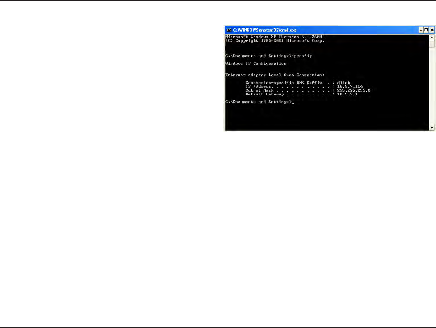
87
D
-
Link
D
A
P
-
2330
U
ser
M
anual
S
e
c
tion
6
-
T
r
oubleshooting
How
to
check
your
IP
addr
ess?
After you install your network adapt
er
,
by
default
,
the TCP/IP
settings
should
be
set
to obtain
an IP address
from
a DHCP server (i.e.
wireless
router) aut
oma
tically
.
To verify your IP
addr
ess
,
please
follow the steps
belo
w
.
Click
on
S
tar
t
>
Run. In
the run box type
cmd and click
OK
.
At the pr
ompt
,
type ipconfig
and press
En
t
er
.
This
will
display
the
IP
addr
ess
,
subnet
mask
,
and
the
default
ga
t
ew
a
y
of
your adapt
er
.
If the
address is 0.0.0.0,
check your adapter installation, security settings
,
and
the
settings
on
your r
out
er
.
S
ome
firewall
sof
t
w
ar
e
programs
may
block a DHCP request
on
newly installed adapt
ers
.
If
you are connecting
to
a wireless network
at
a
hotspot
(e.g.
hot
el
,
coffee shop
,
airport), please
contact an employee
or
administrator
to verify
their
wireless network settings
.
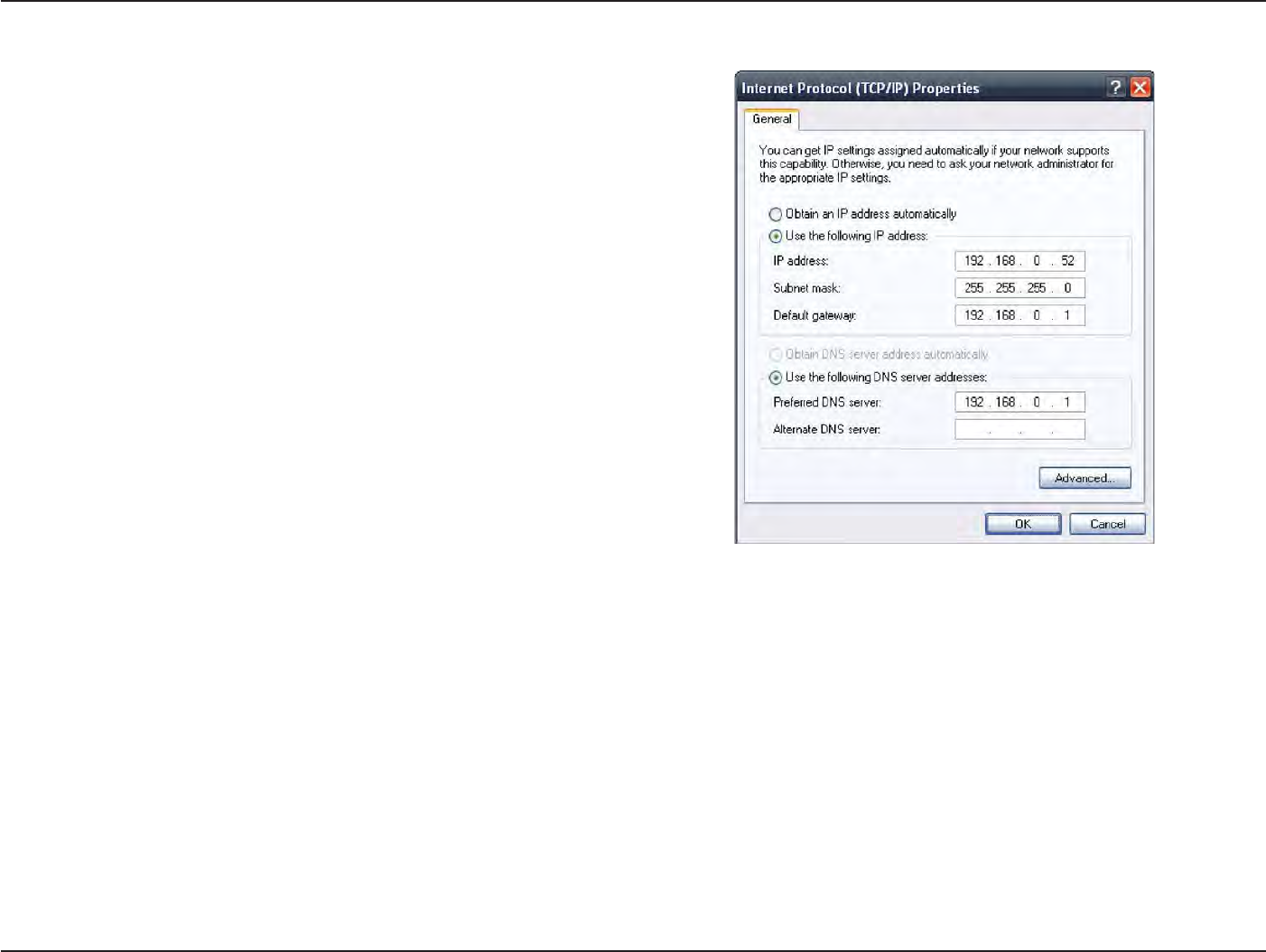
88
D
-
Link
D
A
P
-
2330
U
ser
M
anual
S
e
c
tion
6
-
T
r
oubleshooting
How
to
statically
assign
an
IP
address?
If
you are
not
using a DHCP capable
ga
t
ew
a
y/rout
er
,
or
you need
t
o
assign a static IP
addr
ess
,
please
follow the
steps
belo
w
:
S
t
ep
1:
W
indo
w
s®
2000: Click
on
S
tar
t
>
S
ettings
>
Control Panel
> Network
C
onnec
tions
W
indo
w
s
XP: Click
on
S
tar
t
>
Control Panel
>
Network
C
onnec
tions
W
indo
w
s
Vista®: Click
on
S
tar
t
>
Control Panel
>
Network and Internet
>
Network and Sharing
C
en
t
er
>
Manage network
connections
S
t
ep
2:
R
igh
t
-click
on the
Local Area Connection which represents your
network
adapter and
selec
t
P
roper
ties
.
S
t
ep
3:
Highlight
Internet
P
r
ot
oc
ol
(TCP/IP) and click
P
roper
ties
.
S
t
ep
4:
Click Use
the following
IP address
and enter an
IP address
that
is
on the
same subnet as
your network
or the
LAN IP address
on
your r
out
er
.
Example:
If the
r
out
er’
s
LAN IP address is 192.168.0.1, make your IP
address 192.168.0.X where X is a
number between
2
and 99. Make
sure
that the
number you choose is
not in
use
on the
net
w
or
k
.
Set
Default
Ga
t
ew
a
y
the
same as
the
LAN IP address
of
your
router (192.168.0.1).
Set Primary DNS
the
same as
the
LAN IP address
of
your
router
(192.168.0.1). The
S
ec
ondar
y
DNS is
not
needed
or
you may enter
a
DNS
server
from
your
IS
P
.
S
t
ep
5:
Click OK
twice to
save your
settings
.

89
D
-
Link
D
A
P
-
2330
U
ser
M
anual
Appendix
C - Technical
Specifica
tions
S
tandar
ds
•
IEEE
802.11n
•
IEEE
802.11g
•
IEEE
802.3
•
IEEE
802.3u
•
IEEE
802.3b
•
IEEE
802.3af
•
IEEE
802.3x
Network
Managemen
t
Technical
Specifications
LEDs
•
P
o
w
er/S
ta
tus
Temperature
•
Operating: 0˚C
to 40˚C
•
S
t
oring:
-20˚C
to 65˚C
Humidit
y
•
Operating: 10%~90%
(non-condensing)
•
S
t
oring:
5%~95%
(non-condensing)
•
Web Browser
in
t
erfac
e
(HTTP,
S
ecur
e
HTTP (HT
TPS))
•
Central
WiFiManager
•
SNMP
Support
(P
riv
a
t
e
MIB)
•
Command Line
I
n
t
erfac
e
(
T
elnet
,
S
ecur
e
SSH T
elnet)
S
ecurit
y
•
WPA™ P
ersonal/En
t
er
pr
ise
•
WPA2™ P
ersonal/En
t
er
pr
ise
•
WEP™
64-/128-bit
Wireless Frequency
R
ange
•
2.4
to
2.4835
GHz
Operating Voltage
•
48V DC
+/-
10%
for
PoE
or 12V/1A
C
er
tifications
•
FCC Class B
•
CE
•
UL
•
IC
•
C-
T
ick
•
CSA
•
Wi-Fi
Dimensions
•
L
=
170
mm
•
W
=
170
mm
•
H
=
28
mm
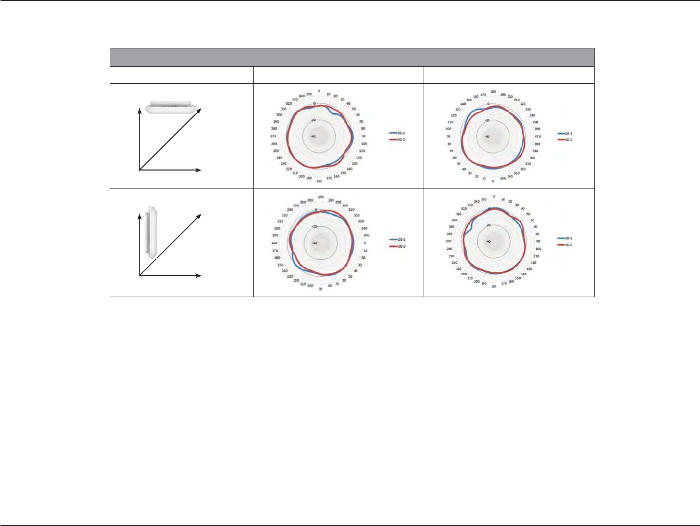
90
D
-
Link
D
A
P
-
2330
U
ser
M
anual
A
ppendix
D
-
Ant
enna
P
a
t
t
e
r
n
W
all
(E-
P
lane)
W
all
(E-
P
lane)
A
n
t
enna
P
a
tt
ern
Antenna
P
a
tt
e
r
ns
Orientation
H
-
P
lan
e
E-P
lan
e
2.4 GHz Ceiling
Moun
t
e
d
Z
Y
X
F
loor
(H-
P
lane)
2.4 G
H
z
Wall
Mounted
Z
Y
X
F
loor
(H-
P
lane)

91
D
-
Link
D
A
P
-
2330
U
ser
M
anual
A
ppendix
D
-
Ant
enna
P
a
t
t
e
r
n
C
on
tac
ting
Technical
Suppor
t
U.S.
and Canadian customers can
contact
D-Link
t
echnical
support
through our web
site
or by
phone
.
Before
you contact
t
echnical
suppor
t
,
please have
the following
r
eady
:
• Model number
of the product
(e.g.
DAP-2330)
• Hardware
R
evision
(loca
t
ed
on the
label
on the
device (e.g. rev
A1))
•
S
erial
Number (s/n number
loca
t
ed
on the
label
on the device).
You
can find
sof
t
w
are
upda
t
es
and
user
documentation on the
D-Link
website
as
well
as
frequently
asked questions
and
answers
to
t
echnical
issues
.
For customers within
the
United
S
ta
t
es:
Phone
Supp
ort:
(877) 453-5465
Internet
Supp
ort:
h
ttp://suppor
t
.dlink
.c
om
For customers within
C
anada:
Phone
Supp
ort:
(800) 361-5265
Internet
Supp
ort:
h
ttp://suppor
t
.dlink
.ca

92
D
-
Link
D
A
P
-
2330
U
ser
M
anual
A
ppendix
E
-
W
a
r
r
a
n
t
y
W
arr
an
t
y
Subjec
t
to the
t
erms
and conditions set
forth
herein, D-Link Systems,
I
nc
.
(“D-Link”) provides this Limited
W
ar
r
an
t
y
:
• Only
to the
person
or entity that
originally purchased
the product from
D-Link
or its
authorized reseller
or
distr
ibut
or
,
and
• Only
for
products purchased and delivered
within the fifty
sta
t
es
of the
United
S
ta
t
es
,
the
District
of
Columbia,
U.S. P
ossessions
or
P
r
ot
ec
t
or
a
t
es
,
U.S.
Military
I
nstalla
tions
,
or
addresses
with
an APO
or
FPO
.
Limited Warran
t
y
:
D-Link warrants
that the
hardware
portion of the
D-Link
product
described
below
(“Hardware”)
will
be free
from
ma
t
erial
defects
in workmanship
and ma
t
er
ials
under normal use
from the
date
of
original retail purchase
of the pr
oduc
t
,
for the
period set
forth below
(“
W
ar
r
an
t
y
Period”),
except
as
otherwise
sta
t
ed
herein.
• Hardware (excluding power supplies and fans): One (1)
year
• Power supplies and fans: One (1)
year
• Spare parts and spare kits: Ninety (90)
day
s
The customer’s
sole and
exclusive
remedy and the entire liability of D-Link and its
suppliers
under this Limited
W
ar
r
an
t
y
will
be
,
at
D-Link’s
option, to
repair
or
replace
the
defective Hardware
during the
W
ar
r
an
t
y
Period
at no
charge
to the
original owner
or to
refund
the actual
purchase
price
paid
.
Any repair or
r
eplacemen
t
will be
rendered
by
D-Link
at an
Authorized D-Link
S
ervic
e
O
ffic
e
.
The
r
eplacemen
t
hardware
need
not be new or
have an identical make
,
model or
par
t
.
D-Link may
,
at its option,
replace
the
defective Hardware
or
any
part
thereof
with any
reconditioned product
that
D-Link reasonably determines
is
substantially
equivalent
(or
super
ior)
in
all
ma
t
erial
respects
to
the
defective
Har
dw
ar
e
.
R
epaired
or
r
eplacemen
t
hardware
will be
warranted
for the
remainder
of the
original
W
ar
r
an
t
y
Period
or ninety
(90) days,
whichever
is
longer
,
and is subjec
t
to the
same
limitations
and
e
xclusions
.
If
a
ma
t
erial
defect is incapable
of
correction,
or if
D-Link determines
that it
is
not practical
to
repair
or
replace
the
defective
Har
dw
ar
e
,
the
actual price
paid by the
original purchaser
for the
defective Hardware
will be
refunded
by D-Link
upon
return
to
D-Link of
the
defective
Har
dw
ar
e
.
All Hardware
or
part thereof
that
is
r
eplaced
b
y
D-Link
,
or
for which
the
purchase price
is
refunded
,
shall become
the property of
D-Link
upon
r
eplacemen
t
or
refund
.

93
D
-
Link
D
A
P
-
2330
U
ser
M
anual
A
ppendix
E
-
W
a
r
r
a
n
t
y
Limited Software Warran
t
y
:
D-Link warrants
that the
sof
t
w
ar
e
portion of the product
(“S
of
t
w
ar
e
”)
will
substantially conform
to
D-Link’s
then
current functional
specifications
for the
S
of
t
w
ar
e
,
as set
forth in the
applicable documentation,
from the
date
of
original retail purchase
of the
S
of
t
w
ar
e
for
a period
of ninety (90)
days
(“S
of
t
w
ar
e
W
ar
r
an
t
y
Period”),
provided that the
S
of
t
w
ar
e
is properly
installed
on
approved hardware
and
operated
as
contemplated
in its
documentation. D-Link
further
warrants
tha
t
,
during the
S
of
t
w
ar
e
W
ar
r
an
t
y
P
er
iod
,
the
magnetic media
on
which D-Link delivers
the
S
of
t
w
ar
e
will
be free
of
physical
def
ec
ts
.
The customer’s sole and exclusive remedy and
the
entire
liability of
D-Link and its suppliers under this Limited
Warranty
will
be
,
at
D-Link’s
option, to
replace
the non-conforming
S
of
t
w
ar
e
(or
defective media)
with
sof
t
w
ar
e
that
substantially conforms
to
D-Link’
s
functional specifications
for the
S
of
t
w
ar
e
or to refund the portion of the
actual purchase price
paid that
is
attributable to the
S
of
t
w
ar
e
.
Except as
otherwise agreed by DLink
in wr
iting
,
the r
eplacemen
t
S
of
t
w
ar
e
is
provided only
to
the original lic
ensee
,
and is
subjec
t
to
the
t
erms
and
conditions
of the
license
granted
by
D-Link
for the
S
of
t
w
ar
e
.
R
eplacemen
t
S
of
t
w
ar
e
will
be warranted
for the
remainder
of the
original
W
ar
r
an
t
y
Period and
is
subjec
t
to
the
same
limitations
and
e
xclusions
.
I
f
a
ma
t
erial
non-conformance
is
incapable
of
correction,
or
if
D-Link determines
in
its
sole
discretion
that it is not
practical
to
replace
the
non-conforming
S
of
t
w
ar
e
,
the price paid by the original
licensee
for the
non-conforming
S
of
t
w
ar
e
will be
refunded
by
D-Link
;
provided
that the
non-conforming
S
of
t
w
ar
e
(and all copies
thereof
) is first returned
to
D-Link
.
The license
granted
respecting
any
S
of
t
w
ar
e
for
which a refund is given automatically
t
er
mina
t
es
.
Non-Applicability
of
Warran
t
y
:
The Limited
W
ar
r
an
t
y
provided hereunder
for
Hardware and
S
of
t
w
ar
e
portions
of
D-Link’s products
will not be
applied
to
and does
not
cover
any
refurbished
product
and any
product
purchased
through the
inventory
clearance
or liquidation
sale
or other
sales
in which
D-Link
,
the
sellers,
or
the
liquidators
expressly disclaim
their
warranty
obligation
pertaining
to the product
and
in that
case,
the product
is being
sold
“
A
s-Is
”
without any
w
a
rr
a
n
t
y
whatsoever
i
n
cl
u
din
g
,
without
li
m
it
a
t
i
on
,
t
h
e
L
i
m
i
t
e
d
W
a
rr
an
t
y
as
d
e
s
cr
i
b
e
d
h
e
r
e
i
n
,
notwithstanding
a
n
y
t
h
in
g
s
ta
t
e
d
he
r
e
in
to
t
h
e
c
on
t
r
a
r
y
.
Submitting A
C
laim:
The customer shall return
the product to the
original purchase
point
based
on
its return polic
y
.
In case
the
return policy period has expired and
the
product
is
within
w
ar
r
an
t
y
,
the
customer shall submit a claim
to
D-Link as
outlined
belo
w
:
• The customer
must submit with the product
as
part of the claim a written description of the
Hardware
defect or
S
of
t
w
ar
e
nonconformance
in
sufficient
detail to allow
D-Link
to confirm the
same, along
with proof of
purchase
of the product
(such as
a
copy
of the
dated
purchase invoice
for the
product)
if the product
is
not
r
eg
ist
ered
.
• T
he
customer must
obtain
a
C
ase
ID
Number
fr
om
D-Link
Technical Suppor
t
(USA
1-877-453-5465
or
Canada 1-800-361-5265),
who
will attempt to
assist
the customer
in
resolving any
suspec
t
ed
defects
with
the produc
t
.
If the product
is considered
def
ec
tiv
e
,
the
customer must
obtain
a
R
eturn
M
a
t
erial
Authorization
(“RMA”) number
by
completing
the
RMA form.
En
t
er
the
assigned Case
ID
Number
at
https://rma.dlink.com/
(USA only)
or
https://rma.dlink.ca
(Canada
only).

94
D
-
Link
D
A
P
-
2330
U
ser
M
anual
A
ppendix
E
-
W
a
r
r
a
n
t
y
•
A
f
t
er
an
RM
A
number
is
issued
,
the
defective
product must be
packaged
secur
ely
in
the
original or
other
suitable shipping
package
to
ensure
that it will not
be damaged
in
tr
ansit
,
and the RMA
number must be prominently marked on the outside
of
the
package
.
Do
not
include any manuals
or
accessories
in the
shipping
package
.
D-Link
will
only replace
the
defective
portion of the product
and
will not
ship back any
accessories
.
• T
he
customer
is
r
esponsible
f
or
all
in-bound
shipping charges
to
D-Link
.
No
C
ash
on
D
eliv
ery
(“COD”) is
allo
w
ed
.
P
roduc
ts
sen
t
C
OD
will
either
be
r
ejec
t
ed
by
D-Link
or
become
the property of
D-Link
.
Products shall
be fully
insured
by the
customer and
shipped
to
D-Link Systems,
I
nc
.
•
USA residents
send
to
17595
Mt
.
Herrmann,
F
ountain
Valley, CA 92708. D-Link
will not
be held responsible
for
any packages
tha
t
are
lost in
transit
to
D-Link
.
The repaired
or
replaced packages
will be
shipped
to the
customer via
UPS
Ground
or
any
common
carrier
selec
t
ed
by
D-Link
.
R
eturn
shipping
charges shall
be
prepaid by D-Link
if
you
use
an
address
in
the
United
S
ta
t
es
,
otherwise
we will
ship
the product to you freight
c
ollec
t
.
Expedited shipping is available
upon
request and
provided
shipping charges
are
prepaid
by the
cust
omer
.
D-Link may
r
ejec
t
or return
any
product that
is
not
packaged and shipped
in
strict compliance
with the
foregoing requir
ements
,
or
for
which an RMA number is
not
visible
from the
outside
of the
package
.
The
product
owner agrees
t
o
pay D-Link’s reasonable handling and
return
shipping charges
for
any
product that
is
not
packaged and shipped
in accordance
with the
foregoing requir
ements
,
or that
is determined
by
D-Link
not to be
defective
or
non-
c
onf
or
ming
.
•
Canadian
r
esiden
ts
send
to
D-Link Net
w
or
ks
,
Inc.,
2525
Meadowvale Boulevard
Mississauga,
On
tar
io
,
L5N
5S2
C
anada.
D-Link
will
not be held
responsible
for
any packages
that
are
lost in
transit
to
D-Link
.
The repaired
or
replaced packages
will be
shipped
t
o
the
customer via
P
ur
ola
t
or
Canada or any common carrier selec
t
ed
by
D-Link
.
R
eturn
shipping charges shall be prepaid by
D-Link
if you
use an address
in
Canada, otherwise
we will
ship
the product to you freight
c
ollec
t
.
Expedited shipping is available
upon
request and provided shipping charges are prepaid by the
cust
omer
.
D-Link may
r
ejec
t
or return any
product
that
is
not packaged
and shipped
in
strict compliance
with the
foregoing requir
ements
,
or for
which an RMA
number is
not
visible
from the
outside
of
the
package
.
The
product
owner agrees
to
pay D-Link’s reasonable handling and
return
shipping charges
for
any
product that is
not
packaged and shipped
in
accordance
with the
foregoing requir
ements
,
or that
is
determined
by
D-Link
not to
be defective
or
non-
c
onf
or
ming
.
RMA phone
number
:
1-800-361-5265 Hours
of
Operation:
Monda
y
-F
r
iday
,
9:00AM – 9:00PM EST
What Is
Not
C
over
ed:
The Limited
W
ar
r
an
t
y
provided herein
by
D-Link does
not
c
ov
er
:
P
roduc
ts
tha
t
,
in
D-Link’
s
judg
men
t
,
ha
v
e
been
subjec
t
ed
to
abuse
,
ac
ciden
t
,
alt
er
a
tion,
modification, tamper
ing
,
negligenc
e
,
misuse
,
fault
y
installation,
lack
of
reasonable care, repair or service
in
any way
that
is
not
contemplated
in
the documentation
for
the produc
t
,
or
if
the model or serial
number
has been
alt
ered
,
tampered
with,
defaced
or
removed;
Initial
installation, installation
and
removal
of the product for
r
epair
,
and shipping costs;
Operational adjustments covered
in the
operating manual
for the pr
oduc
t
,
and normal main
t
enanc
e;
Damage
that
occurs
in
shipmen
t
,
due
to act
of
G
od
,
failures
due to power
surge
,
and
cosmetic damage; Any har
dw
ar
e
,
sof
t
w
ar
e
,
firmware
or other
products
or
services
provided by anyone
other
than
D-Link
;
and Products
that
have been purchased
from
inventory
clearance
or liquidation
sales
or other
sales
in
which
D-Link
,
the
sellers
,
or the
liquidators
expressly disclaim
their
warranty
obligation
pertaining
to the pr
oduc
t
.

95
D
-
Link
D
A
P
-
2330
U
ser
M
anual
A
ppendix
E
-
W
a
r
r
a
n
t
y
While necessary
main
t
enanc
e
or
repairs
on
your
P
roduc
t
can
be
performed
b
y
any
c
ompan
y
,
w
e
r
ec
ommend
that
y
ou
use
only
an
Authorized
D-Link
S
ervic
e
O
ffic
e
.
Improper
or
incorrectly performed main
t
enanc
e
or
repair voids this Limited
W
ar
r
an
t
y
.
Disclaimer
of
Other Warran
ties:
EXCEPT FOR
THE
LIMITED
WARRANTY
SPECIFIED
HEREIN,
THE
PRODUCT
IS
PR
OVIDED
“AS-IS”WITHOUT
AN
Y
WARRANTY OF
ANY KIND
WHA
TSOE
VER
INCLUDING, WITHOUT LIMITATION, ANY WARRANTY OF MERCHANTABILITY,
FITNESS FOR A PARTICULAR PURPOSE AND
NONINFRINGEMENT
.
IF
ANY
IMPLIED
WARRANTY CANNOT
BE
DISCLAIMED
IN
AN
Y
TERRIT
ORY
WHERE
A
PRODUCT
IS
SOLD
,
THE
DURATION OF
SUCH
IMPLIED
W
ARR
ANT
Y
SHALL BE LIMITED TO THE DURATION OF THE APPLICABLE WARRANTY PERIOD
SET FORTH ABOVE. EXCEPT AS EXPRESSLY COVERED
UNDER THE
LIMITED WARRANTY PROVIDED HEREIN, THE ENTIRE RISK AS TO THE QUALITY, SELECTION AND PERFORMANCE OF THE PRODUCT IS WITH THE
PURCHASER OF THE
PR
ODUC
T
.
Limitation
of
Liability
:
TO THE MAXIMUM
EXTENT PERMITTED BY LAW, D-LINK IS NOT LIABLE UNDER ANY CONTRACT, NEGLIGENCE, STRICT
LIABILITY OR OTHER LEGAL
OR
EQUITABLE
THEORY FOR ANY LOSS OF USE
OF
THE PRODUCT, INCONVENIENCE OR DAMAGES OF ANY CHARACTER, WHETHER DIRECT, SPECIAL,
INCIDENTAL OR CONSEQUENTIAL (INCLUDING, BUT NOT LIMITED TO, DAMAGES FOR LOSS OF GOODWILL, LOSS OF REVENUE OR PROFIT,
WORK
STOPPAGE, COMPUTER FAILURE OR
MALFUNCTION, FAILURE OF OTHER EQUIPMENT OR COMPUTER PROGRAMS TO WHICH D-LINK’S
PR
ODUC
T
IS CONNECTED WITH, LOSS OF INFORMATION OR DATA CONTAINED IN, STORED
ON, OR INTEGRATED WITH ANY PRODUCT RETURNED TO
D-LINK
FOR WARRANTY
SERVICE) RESULTING FROM THE USE
OF THE PRODUCT, RELATING TO WARRANTY
SERVICE, OR ARISING OUT OF ANY BREACH
OF
THIS LIMITED WARRANTY, EVEN IF D-LINK HAS BEEN ADVISED OF THE POSSIBILITY OF SUCH DAMAGES. THE SOLE REMEDY FOR
A
BREACH
OF
THE FOREGOING LIMITED WARRANTY IS REPAIR, REPLACEMENT OR REFUND OF THE DEFECTIVE OR
NONCONFORMING PRODUCT. THE
MAXIMUM
LIABILITY OF D-LINK UNDER
THIS
WARRANTY
IS
LIMITED
T
O
THE PURCHASE PRICE
OF
THE PRODUCT COVERED BY
THE
W
ARR
ANT
Y
.
THE FOREGOING
EXPRESS WRITTEN WARRANTIES AND REMEDIES ARE EXCLUSIVE AND ARE IN LIEU OF ANY OTHER WARRANTIES OR REMEDIES, EXPRESS,
IMPLIED
OR
ST
A
TUT
ORY
.
Governing
L
a
w
:
This Limited
W
ar
r
an
t
y
shall
be
governed
by the
laws
of the
S
ta
t
e
of
California.
S
ome
sta
t
es
do not allow
exclusion
or limitation of incidental or
consequential damages
,
or limitations on how long an implied
warranty
lasts,
so the foregoing limitations and
exclusions
may not
apply
.
T
his
Limited
W
ar
r
an
t
y
provides specific legal rights and you may also have
other
rights which vary
from
sta
t
e
to
sta
t
e
.
T
r
ademar
ks:
D-Link is
a
registered trademark
of
D-Link Corporation/D-Link
Systems,
I
nc
.
Other trademarks
or
registered trademarks are
the property of their
respective
o
wners
.
Copyright
S
ta
t
ement:
No part of this publication or
documentation accompanying
this product
may
be
reproduced
in
any
form or by
any means
or
used
to
make
any

96
D
-
Link
D
A
P
-
2330
U
ser
M
anual
A
ppendix
E
-
W
a
r
r
a
n
t
y
derivative such
as
translation, transformation, or adaptation
without
permission
from
D-Link Corporation/D-Link
Systems, Inc., as
stipulated by
the
United
S
ta
t
es
C
op
yr
igh
t
A
c
t
of
1976 and any amendments
thereto
.
C
on
t
ents
are
subjec
t
to
change
without prior notic
e
.
C
op
yr
igh
t
©2011
by
D-Link Corporation/D-Link
Systems,
I
nc
.
All
rights r
eser
v
ed
.
CE
M
ar
k
Warning:
This
is a
Class B pr
oduc
t
.
In a
domestic
en
vironmen
t
,
this product
may cause
radio
in
t
er
f
erenc
e
,
in which
case
the
user may
be
required
to take
adequa
t
e
measur
es
.
Federal Communication Commission Interference
S
ta
t
emen
t
T
his
equipment
has
be
en
t
ested
and
f
oun
d
to
comply
with
t
he
limits
f
or
a
Class
B
digital
devic
e
,
p
ursuan
t
to
P
ar
t
15
of
th
e
FCC Rules. T
he
se
limits
are
designed
to
provide reasonable
protection
agai
ns
t
h
ar
mful
i
n
t
er
f
eren
ce
in
a
r
es
id
en
t
i
al
i
nst
alla
ti
on
.
This e
qu
ip
men
t
g
ene
r
a
t
e
s
,
uses a
nd
can
radiate
radio
frequency ener
gy
and
,
if not
installed
and
used
in
accordance
with
the
instructions
,
may
cause
harmful
in
t
er
f
erenc
e
to
radio
c
ommunications
.
Ho
w
ever
,
there
is
no
guaran
t
ee
that
in
t
er
f
erenc
e
will not
occur
in
a
par
ticular
installation.
I
f
this
equipmen
t
does
cause
harmful
in
t
er
f
erenc
e
to radio
or
t
elevision
reception, which can be determined
by turning the
equipment
off
and on,
the
user is encouraged
to try to
c
orr
ec
t
the
in
t
er
f
erenc
e
by
one
of the following
measur
es:
-
R
eor
ien
t
or
r
eloca
t
e
the
receiving
antenna.
-
Increase
the
separation between
the equipment
and
r
ec
eiver
.
-
C
onnec
t
the equipment into
an
outlet on
a circuit
different from that to
which
the
receiver is c
onnec
t
ed
.
-
Consult
the
dealer
or
an experienced radio/TV
t
echnician
for
help
.
This device complies
with
P
ar
t
15 of the
FCC Rules.
Operation
is
subjec
t
to the following two
conditions: (1) This device may
not
cause
harmful
in
t
er
f
erenc
e
,
and (2) this device must accept any
in
t
er
f
erenc
e
r
ec
eived
,
including
in
t
er
f
erenc
e
that
may cause undesired
operation.
FCC Caution:
Any
changes
or
modifications
not
expressly approved
by the party
responsible
for
compliance
could void the
user’s
authority
t
o
oper
a
t
e
this equipmen
t
.
802.11g operation
of
this
product in the
U.S.A. is
firmware-limited
to
channels
1 through 11.
IMPORTANT
NO
TE:
FCC
R
adia
tion
Exposure
S
ta
t
emen
t:
This
equipment
complies
with
FCC
radiation exposure
limits
set
forth for an uncontrolled
en
vironmen
t
.
This
equipment
should
be
installed
and
operated
with minimum
distance 20cm between
the
radiator & your body
.

97
D
-
Link
D
A
P
-
2330
U
ser
M
anual
A
ppendix
E
-
W
a
r
r
a
n
t
y
T
he
a
vailabilit
y
of
some
specific
channels
and/or
oper
a
tional
fr
equency
bands
ar
e
c
oun
tr
y
dependen
t
and
ar
e
fir
m
w
ar
e
pr
ogrammed
a
t
the
fac
t
or
y
t
o
match
the intended
destina
tion.
T
he
firmware setting
is
not
accessible
b
y
the end
user
.
For
detailed warranty information
applicable
to
products purchased outside the United
S
ta
t
es
,
please
contact the corresponding
local D-Link
offic
e
.
This
device and it’s an
t
ennas(s)
must
not
be
c
o
-loca
t
ed
or
operating
in
conjunction
with
any
other
an
t
enna
or
transmitter except
in
accordance
with
FCC
multi-transmitter product pr
oc
edur
es
.
I
ndustry
C
anada
S
ta
t
emen
t
This device complies
with
Industry
C
anada
license-exempt
RSS
standard(s). Operation is
subjec
t
to
the
following two conditions:
1) this device may
not
cause
in
t
er
f
erenc
e
and
2) this device must accept
any
in
t
er
f
erenc
e
,
including
in
t
er
f
erenc
e
that
may cause
undesired operation of
the
device
T
o
r
educ
e
pot
en
tial
radio
in
t
er
f
erenc
e
t
o
other
users
,
the
an
t
enna
t
ype
and
its
gain
should
be
so
chosen
tha
t
the
EIRP
is
not
mor
e
than
requir
ed
f
or
successful
communication.
Le pr
ésen
t
appareil est conforme aux
CNR
d’Industrie Canada applicables aux appareils radio exempts
de
lic
enc
e
.
L’exploitation est autorisée aux
deux
c
onditions
suivan
t
es
:
(1)
l
’appar
eil
ne
doit
pas
produir
e
de
br
ouillage
,
et
(2)
l
’utilisa
t
eur
de
l
’appar
eil
doit
acc
ept
er
tout br
ouillage
r
adioélec
tr
ique
subi,
même
si
le brouillage est susceptible d’en compromettre le
f
onctionnemen
t
.
C
aution:
For
product
available
in
the USA/Canada
mar
ket
,
only channel 1~11 can be
oper
a
t
ed
.
S
elec
tion
of
other channels
is
not
possible
.
Pour les
produits disponibles aux
É
ta
ts-Unis
/
C
anada
du
marché
,
seul le canal
1
à
11
peuv
en
t
être
e
xploit
és
.
S
élec
tion
d’autres canaux
n
’est
pas
possible
.
T
his
devic
e
and
it
’
s
an
t
ennas(s)
must
not
be
c
o
-loca
t
ed
or
oper
a
ting
in
c
onjunc
tion
with
any
other
an
t
enna
or
tr
ansmitt
er
e
x
c
ept
in
acc
or
danc
e
with
IC
multi-
transmitter product pr
oc
edur
es
.
Cet appareil et son
an
t
enne
(s)
ne
doit
pas être co-localisés
ou fonctionnement
en association avec une autre
an
t
enne
ou
tr
ansmett
eur
.
IMPORTANT
NO
TE:
IC
R
adia
tion
Exposure
S
ta
t
emen
t:
T
his
equipmen
t
c
omplies
with
IC
r
adia
tion
e
xposur
e
limits
set
forth
f
or
an
uncon
tr
olled
en
vironmen
t
.
T
his
equipmen
t
should
be
installed
and
oper
a
t
ed
with
minimum
distance 20cm
between the radiator
and your
body
.
C
et
équipemen
t
est
c
onf
orme
aux
limit
es
d
’
e
xposition
aux
r
a
y
onnemen
ts
IC
établies
pour
un
en
vironnemen
t
non
c
on
tr
ôlé
.
C
et
équipemen
t
doit
êtr
e
installé
et utilisé avec un minimum
de 20 cm de distance entre la source de
rayonnement et v
otr
e
c
or
ps
.

98
D
-
Link
D
A
P
-
2330
U
ser
M
anual
Appendix
F
-
R
eg
istr
a
tion
R
eg
istr
a
tion
P
roduc
t
registration is entirely voluntary and failure
to
complete
or return this form will not
diminish your warranty r
igh
ts
.
Version 1.0
May 12,
2014