D Link AP3662A1 Wireless AC1200 Dual Band Outdoor PoE Access Point User Manual
D Link Corporation Wireless AC1200 Dual Band Outdoor PoE Access Point
D Link >
User manual
This document will guide you through the
basic installation process for your new
D-Link Dual Band Outdoor Access Point
Building Networks for People
DAP-3662
Documentation also available
via the D-Link Website
Quick Installation Guide
Wireless AC1200
Concurrent Dual Band Outdoor PoE Access Point
Quick Installation Guide
Краткое руководство по установке
Guía de Instalación Rápida
Guia de Instalação Rápida
快速安裝指南
Petunjuk Pemasangan Cepat
クイックインストールガイド

2
D-Link DAP-3662 Quick Install Guide
2
ENGLISH
Important Information
This product should ONLY be installed by
an experienced installer who is familiar with
local building and safety codes and, where
applicable, is licensed by the appropriate
authorities. Failure to employ an experienced
installer may render the D-Link product
warranty void and may also expose the end
user or the service provider to legal and
nancial liabilities. D-Link and its resellers or
distributors expressly disclaim any and all
liabilities for injury, damage, or violation of
regulations due to the improper installation of
outdoor units or antennas.
A safety grounding system is necessary
to protect your outdoor installation from
lightning strikes and the build-up of static
electricity. Direct grounding of an outdoor AP is
very important and can protect your networks
from brutal outdoor environments and
devastating ESD attacks. The grounding system
must comply with the National Electrical Code
and safety standards that apply in your country
and/or region. Always check with a qualied
electrician if you are in doubt as to whether
your outdoor installation is properly grounded.
Quick Install Guide
This installation guide provides basic
instructions for installing the DAP-3662 Wireless
AC1200 Concurrent Dual Band Outdoor PoE
Access Point on your network. For additional
information about how to use the Access Point,
please see the datasheet and user manual from
the D-Link support website.
Minimum System
Requirements
Computer with Windows, MAC OS, or Linux-
based operating system, and an Ethernet
adapter installed
-Internet Explorer 7.0, Mozilla Firefox®
version 12.0, Safari 4.0, or Chrome 20.0 or
newer
Package Contents
-DAP-3662 Wireless AC1200 Concurrent
Dual Band Outdoor PoE Access Point
-Installation CD-ROM
-Quick Installation Guide
-PoE Injector
-Power Adapter (48 V/ 0.5 A)1
-Mounting kit (Wall/Pole Mount)
-Stainless steel mount base x 1
-Stainless tie back straps x 2
-Wall screw x 4
-Wall plug x4
-Stainless mount screw (hexagonal hole) x1
-Hexagon Socket Spanner
-Two LAN Port Waterproof Enclosure
-Grounding Wire
If any of the above items are missing, please
contact your reseller.
1 Using a power supply with a different voltage rating or
PoE injector than the one included with the DAP-3662
will cause damage and void the warranty for this product.
3
D-Link DAP-3662 Quick Install Guide
3
ENGLISH
Physical Installation
STEP 1: Connect an Ethernet Cable
to the LAN1 (PoE) Port on the AP.
STEP 2: Mount the AP to a Pole or
Wall
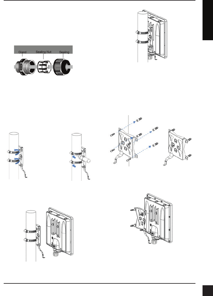
2A: Mounting The DAP-3662 On A
Pole
Secure mount base to the pole with two
stainless tie back strap sets. Ensure that the tie
back is locked securely.
Align the DAP-3662 with the mounting plate
Once aligned, slide the device down so that
the mounting plate securely locks into the
DAP-3662
2B: Mounting The DAP-3662 On A
Wall
Securely mount the base to the wall using
wall plug and wall screw.
Align the DAP-3662 with the mounting plate
4
D-Link DAP-3662 Quick Install Guide
4
ENGLISH
Once aligned, slide the device down so that
the mounting plate securely locks into the
DAP-3662
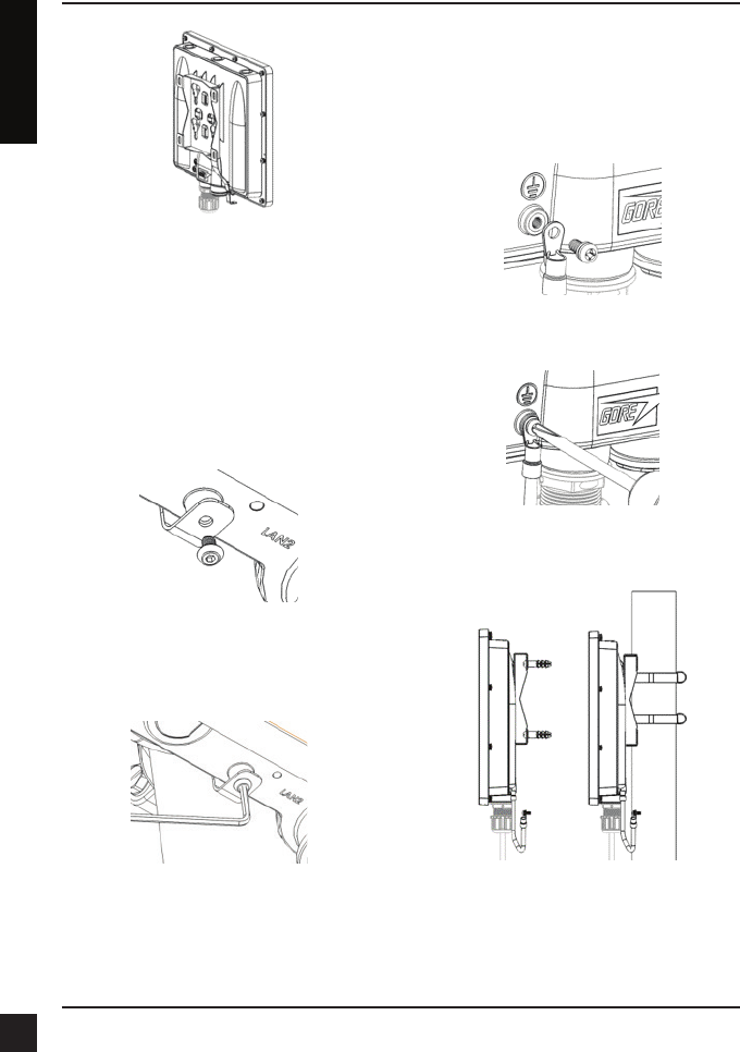
STEP 3: Install Mount Screw to Fix
DAP-3662 On A Mounting (Pole/
Wall Mount base)
Use the included mount screw (hexagonal
hole) to lock the DAP-3662 to the pole/wall
mount
With the included hexagon socket spanner,
tighten the mount screw until the DAP-3662 is
secured.
STEP 4: Connect Grounding Wire
A grounding wire is recommended to protect
your device from lightning strikes and the
buildup of static electricity.
Attach the grounding wire to the DAP-3662 using
the included screw.
Tighten the grounding wire to the DAP-3662 until
it is securely attached.
Attach the other end of the grounding wire to
either the wall or pole mount. Ensure that the
wall or pole mount is connected to an electrical
ground.
5
D-Link DAP-3662 Quick Install Guide
5
ENGLISH
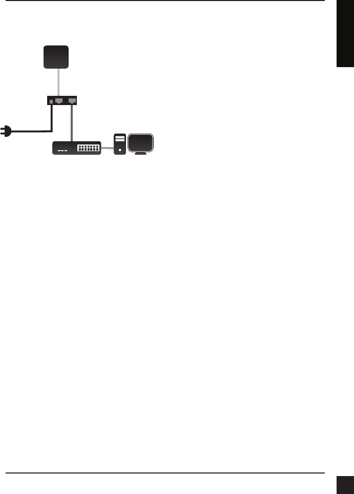
STEP 5: Connect the AP to Your
Network
A. Connect the Ethernet cable (connected
to the AP in STEP 1) from the AP to the
“P+DATA OUT” port on the PoE Injector.
B. Connect an Ethernet cable from a router/
switch or PC to the “DATA IN” port on the
PoE Injector.
C. Attach the power adapter to the connector
labeled “POWER IN” on the PoE Injector,
and attach it into an electrical outlet.
Conguration
If you are configuring the AP locally, connect a
PC to the PoE Injector “DATA IN” port using an
Ethernet cable.
A. Assign a static IP address to your PC which
is in the same network segment with the
device. As the default IP address of this
unit is 192.168.0.50, you may choose any
address from 192.168.0.1 to 192.168.0.254,
except 192.168.0.50.
B. Open a web browser and go to
http://192.168.0.50. Enter admin as your
username and leave the password blank to
log into the web UI. Now you can configure
the AP via web UI.
A
CB
P+DATA OUT
DATA IN
PoE Injector
POWER IN
Router or Switch Computer
AP
LAN1 (PoE)
FCC Statement:
Federal Communication Commission Interference Statement
This equipment has been tested and found to comply with the limits for a Class B digital device, pursuant to Part 15 of
the FCC Rules. These limits are designed to provide reasonable protection against harmful interference in a residential
installation. This equipment generates, uses and can radiate radio frequency energy and, if not installed and used in
accordance with the instructions, may cause harmful interference to radio communications. However, there is no
guarantee that interference will not occur in a particular installation. If this equipment does cause harmful interference to
radio or television reception, which can be determined by turning the equipment off and on, the user is encouraged to try
to correct the interference by one of the following measures:
● Reorient or relocate the receiving antenna.
● Increase the separation between the equipment and receiver.
● Connect the equipment into an outlet on a circuit different from that to which the receiver is connected.
● Consult the dealer or an experienced radio/TV technician for help.
FCC Caution: Any changes or modifications not expressly approved by the party responsible for compliance could void
the user’s authority to operate this equipment.
This device complies with Part 15 of the FCC Rules. Operation is subject to the following two conditions: (1) This device
may not cause harmful interference, and (2) this device must accept any interference received, including interference
that may cause undesired operation.
For product available in the USA/Canada market, only channel 1~11 can be operated. Selection of other channels is not
possible.
This device and it's antennas(s) must not be co-located or operating in conjunction with any other antenna or transmitter
except in accordance with FCC multi-transmitter product procedures.
IMPORTANT NOTE:
FCC Radiation Exposure Statement:
This equipment complies with FCC radiation exposure limits set forth for an uncontrolled environment. This equipment
should be installed and operated with minimum distance 23 cm between the radiator & your body.

IC Statement
This device complies with Industry Canada license-exempt RSS standard(s). Operation is subject to the following two
conditions: (1) this device may not cause interference, and (2) this device must accept any interference, including
interference that may cause undesired operation of the device.
Le présent appareil est conforme aux CNR d'Industrie Canada applicables aux appareils radio exempts de licence. L'exploitation est
autorisée aux deux conditions suivantes : (1) l'appareil ne doit pas produire de brouillage, et (2) l'utilisateur de l'appareil doit
accepter tout brouillage radioélectrique subi, même si le brouillage est susceptible d'en compromettre le fonctionnement.
For product available in the USA/Canada market, only channel 1~11 can be operated. Selection of other channels is not
possible.
Pour les produits disponibles aux États-Unis / Canada du marché, seul le canal 1 à 11 peuvent être exploités. Sélection d'autres
canaux n'est pas possible.
This device and it's antennas(s) must not be co-located or operating in conjunction with any other antenna or transmitter
except in accordance with IC multi-transmitter product procedures.
Cet appareil et son antenne (s) ne doit pas être co-localisés ou fonctionnement en association avec une autre antenne ou
transmetteur.
IMPORTANT NOTE:
IC Radiation Exposure Statement:
This equipment complies with IC RSS-102 radiation exposure limits set forth for an uncontrolled environment. This
equipment should be installed and operated with minimum distance 23 cm between the radiator & your body.
Cet équipement est conforme aux limites d'exposition aux rayonnements IC établies pour un environnement non
contrôlé. Cet équipement doit être installé et utilisé avec un minimum de 23 cm de distance entre la source de
rayonnement et votre corps.
This radio transmitter (Model: DAP-3662A1) has been approved by Industry Canada to operate with the antenna types
listed below with the maximum permissible gain and required antenna impedance for each antenna type indicated.
Antenna types not included in this list, having a gain greater than the maximum gain indicated for that type, are strictly
prohibited for use with this device.
Le présent émetteur radio (Model: DAP-3662A1) a été approuvé par Industrie Canada pour fonctionner avec les types
d'antenne énumérés ci-dessous et ayant un gain admissible maximal et l'impédance requise pour chaque type
d'antenne. Les types d'antenne non inclus dans cette liste, ou dont le gain est supérieur au gain maximal indiqué, sont
strictement interdits pour l'exploitation de l'émetteur.
Antenna list:
Gain (dBi)
Ant. Brand P/N Antenna Type Connector 2.4GHz 5GHz
1 Grand-Tek OA-58-06-03 Embedded Antenna
I-PEX - 6.2
2 Grand-Tek OA-58-05-02 Embedded Antenna
I-PEX - 6.2
3 Grand-Tek OA-24-05-06 Embedded Antenna
I-PEX 6.1 -
4 Grand-Tek OA-24-04-02 Embedded Antenna
I-PEX 4.8 -
Note: The EUT has four antennas.