D Link CS2230A1 Full HD Wireless N Cube Network Camera User Manual
D Link Corporation Full HD Wireless N Cube Network Camera
D Link >
User manual

2D-Link DCS-2210/2230 User Manual
Table of Contents
Product Overview ........................................................ 4
Package Contents ................................................... 4
System Requirements ............................................. 4
Hardware Overview ..................................................... 5
Front ..................................................................5
Rear ................................................................... 6
Side ....................................................................7
Conguration with Wizard ........................................ 8
Conguration ............................................................. 13
Web-based Conguration Utility ............................13
D-ViewCam Setup Wizard ...............................15
Live Video ..............................................................17
Setup .....................................................................19
Wizard .............................................................. 19
Internet Connection Setup Wizard ................... 19
Motion Detection Setup Wizard .......................22
Network Setup .................................................24
Wireless Setup(DCS-2230 only) ...................... 27
Dynamic DNS ..................................................29
Image Setup ....................................................30
Audio and Video ..............................................32
Preset ..............................................................34
Motion Detection .............................................. 36
Time and Date .................................................37
Event Setup .....................................................38
Application .................................................... 39
Add Server .................................................... 40
Add Media ..................................................... 41
Add Event ..................................................... 43
Add Recording .............................................. 45
SD Card ........................................................... 47
Advanced ............................................................... 48
Digital Input/Output .......................................... 48
ICR and IR ....................................................... 49
HTTPS ............................................................. 50
Access List ....................................................... 51
Maintenance ..........................................................52
Device Management ........................................ 52
Backup and Restore ........................................53
Firmware Upgrade ........................................... 54
Status .................................................................... 55
Device Info ....................................................... 55
Logs ................................................................. 56
Help .................................................................57
Appendix .................................................................... 58
DI/DO Input Specications ....................................58
Technical Specications ........................................59
Technical Specications ........................................60

3D-Link DCS-2210/2230 User Manual
D-Link reserves the right to revise this publication and to make changes in the contents hereof without obligation to notify any person or
organization of such revisions or changes.
Manual Revisions
Trademarks
D-Link and the D-Link logo are trademarks or registered trademarks of D-Link Corporation or its subsidiaries in the United States or
other countries. All other company or product names mentioned herein are trademarks or registered trademarks of their respective
companies.
Copyright © 2011 D-Link Corporation.
All rights reserved. This publication may not be reproduced, in whole or in part, without prior expressed written permission from D-Link
Systems, Inc.
Revision Date Description
1.0 June 14, 2011 DCS-2210/2230 Revision A1 with rmware version 1.00
Preface
4D-Link DCS-2210/2230 User Manual
Product OverviewProduct Overview
DCS-2210 or DCS-2230 Network Camera
CAT5 Ethernet cable
Power adapter
Camera stand
CD-ROM with User Manual and software
Quick Installation Guide
If any of the above items are missing, please contact your reseller.
Package Contents
Existing 10/100 Ethernet-based network or 802.11n/g wireless network(Wireless for DCS-2230 )
Computer with Windows 7/Vista/XP for Camera Setup Wizard
Internet Explorer, Firefox, Opera, or other web browser for web interface (Internet Explorer
recommended for full functionality)
If any of the above items are missing, please contact your reseller.
System Requirements
5D-Link DCS-2210/2230 User Manual
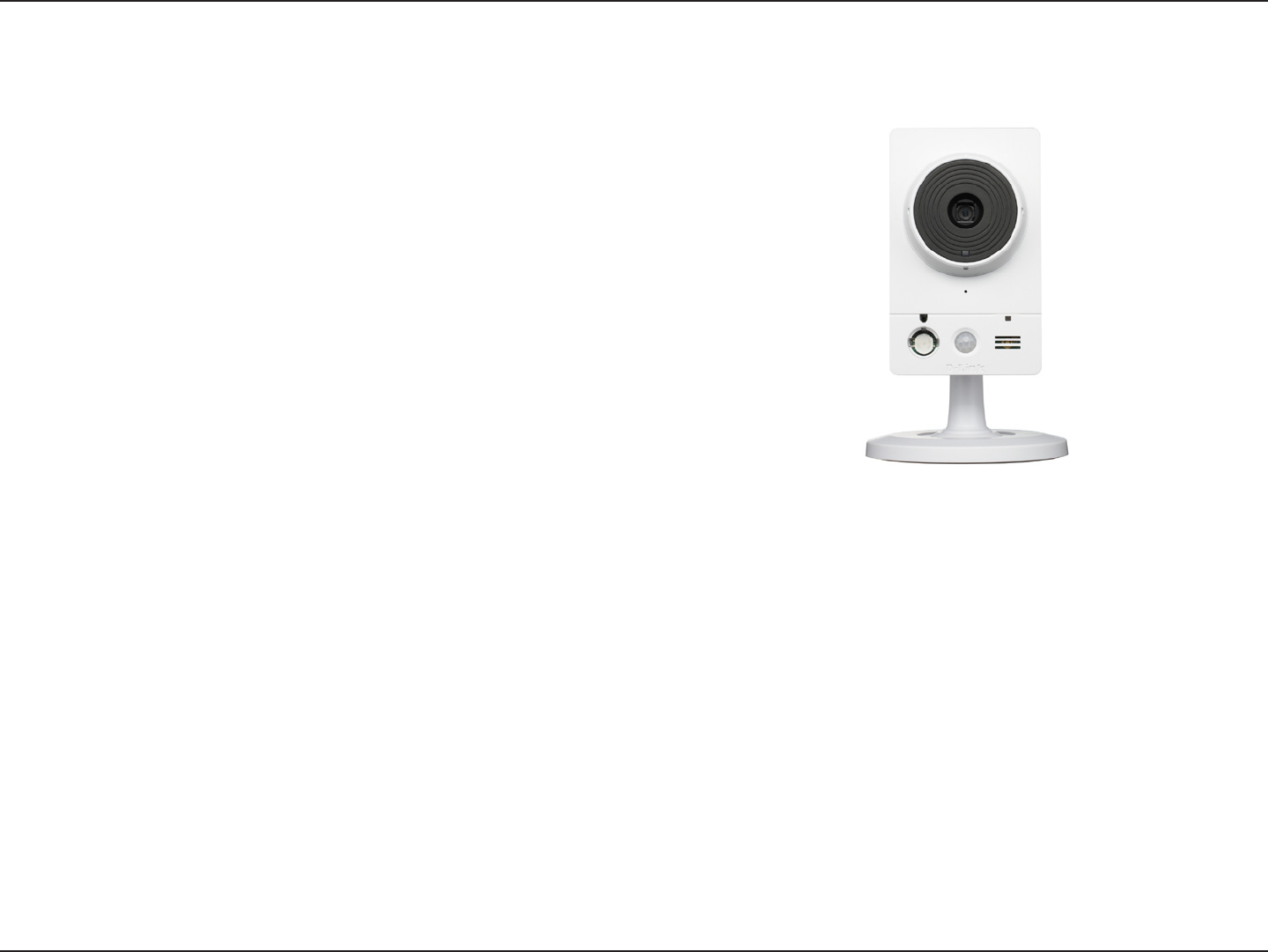
Hardware Overview
Microphone
Records audio from the surrounding
area
WPS LED(DCS-2230 only)
WPS status indicator LED
Speaker
Audio output
Camera Lens
Records video of the surrounding area
Front
Status LED
Indicates the camera's current status
ICR Sensor
The IR-Cut Removable sensor judges
lighting conditions and switches from
color to infrared accordingly
Infrared LED
Used to illuminate the camera's
eld of view at night
PIR
Passive Infrared sensor for motion
detect
Hardware Overview
Hardware Overview
6D-Link DCS-2210/2230 User Manual
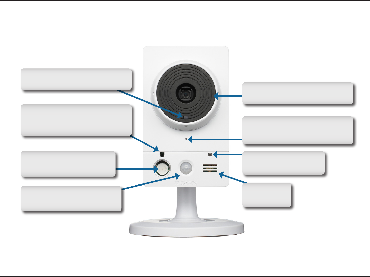
Hardware Overview
Rear
I/O Connector
I/O connectors for external devices
Reset
Press and hold this button for 10 seconds
to reset the camera
Ethernet
RJ45 connector for Ethernet (DCS-2210
support PoE which can also be used to
power the camera)
Power Connector
Connects to the included DC 5 V
power adapter
Adjustment Ring
Tighten or loosen the adjustment
ring to adjust the camera's position
WPS Button (DCS-2230 only)
Press this button, then press the WPS
button on your router to set up a wireless
connection automatically
Base Holes
Can be used with cable ties to
attach camera to a surface
7D-Link DCS-2210/2230 User Manual
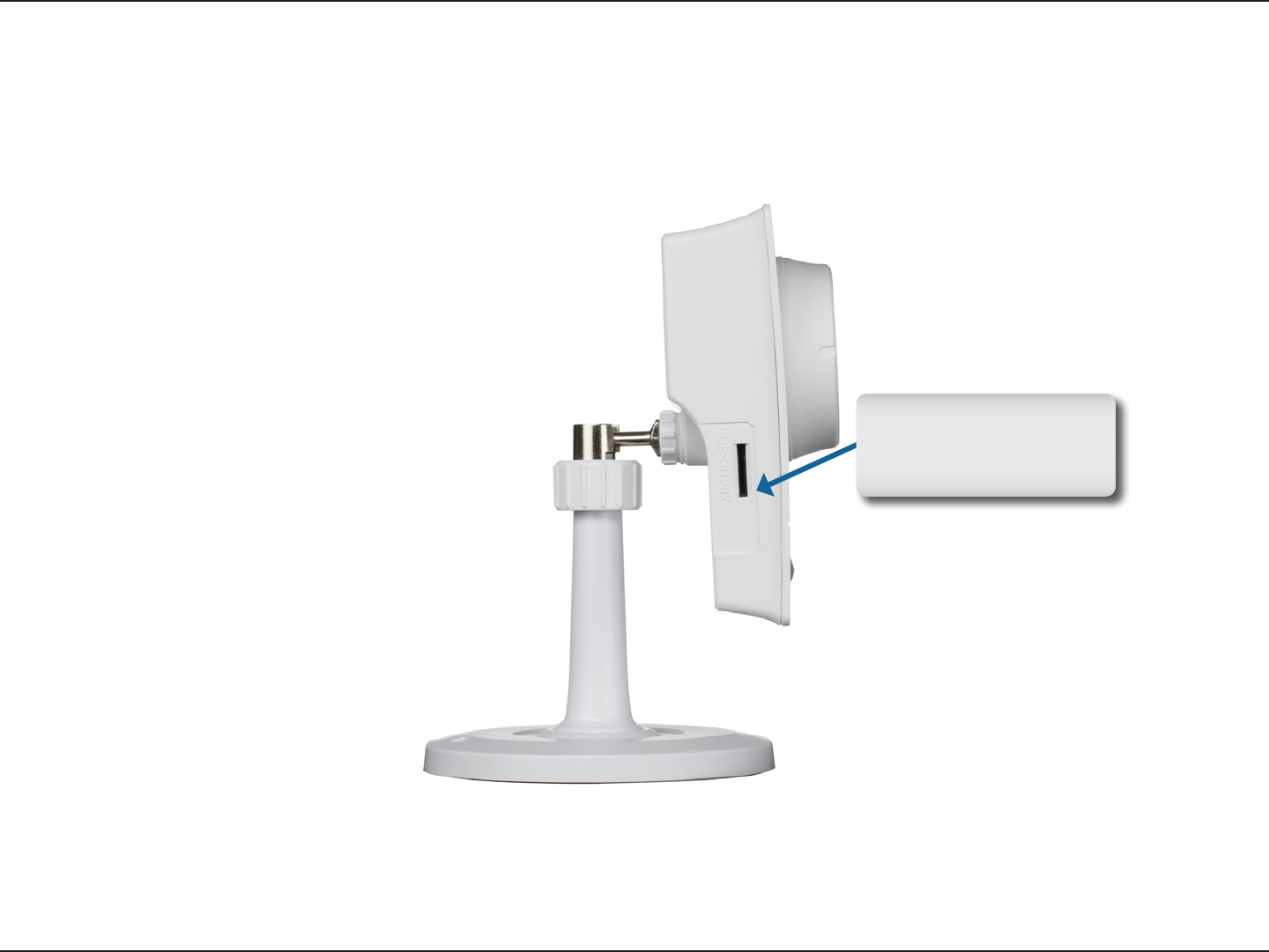
Hardware Overview
Micro SD Card slot
Local storage for storing
recorded image and video
Side
8D-Link DCS-2210/2230 User Manual
Hardware Overview
Conguration with Wizard
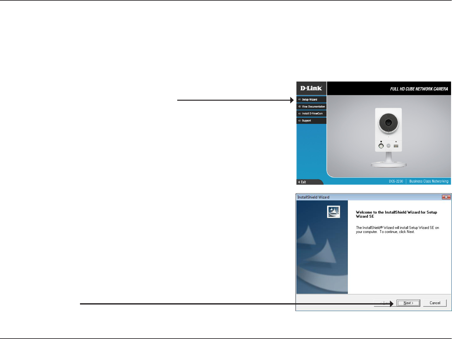
Insert the DCS-2210/DCS-2230 CD into your computer's CD-ROM drive to begin the installation. If the Autorun function on your
computer is disabled, or if the D-Link Launcher fails to start automatically, click Start > Run. Type D:\autorun.exe, where D: represents
the drive letter of your CD-ROM drive.
Click Installation Wizard to begin the installation.
After clicking Setup Wizard, the window on the right will open.
Click Next to continue.
9D-Link DCS-2210/2230 User Manual
Hardware Overview
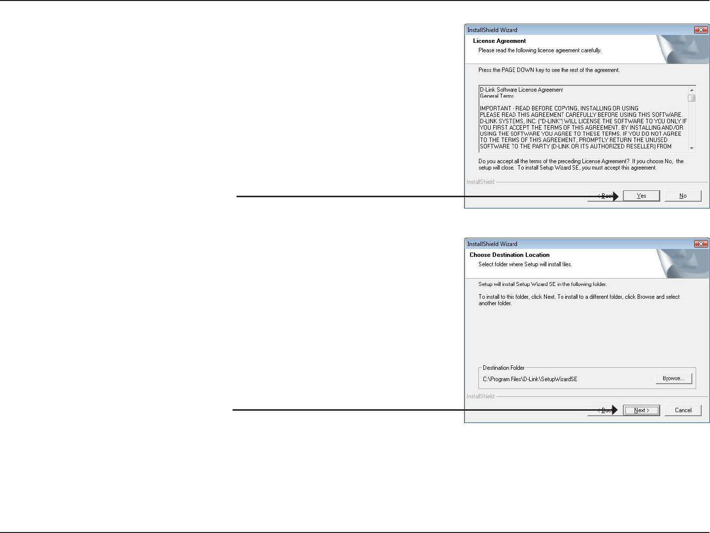
Click Yes to accept the License Agreement.
To start the installation process, click Next.
Note: The installation may take several minutes to nish.
10D-Link DCS-2210/2230 User Manual
Hardware Overview
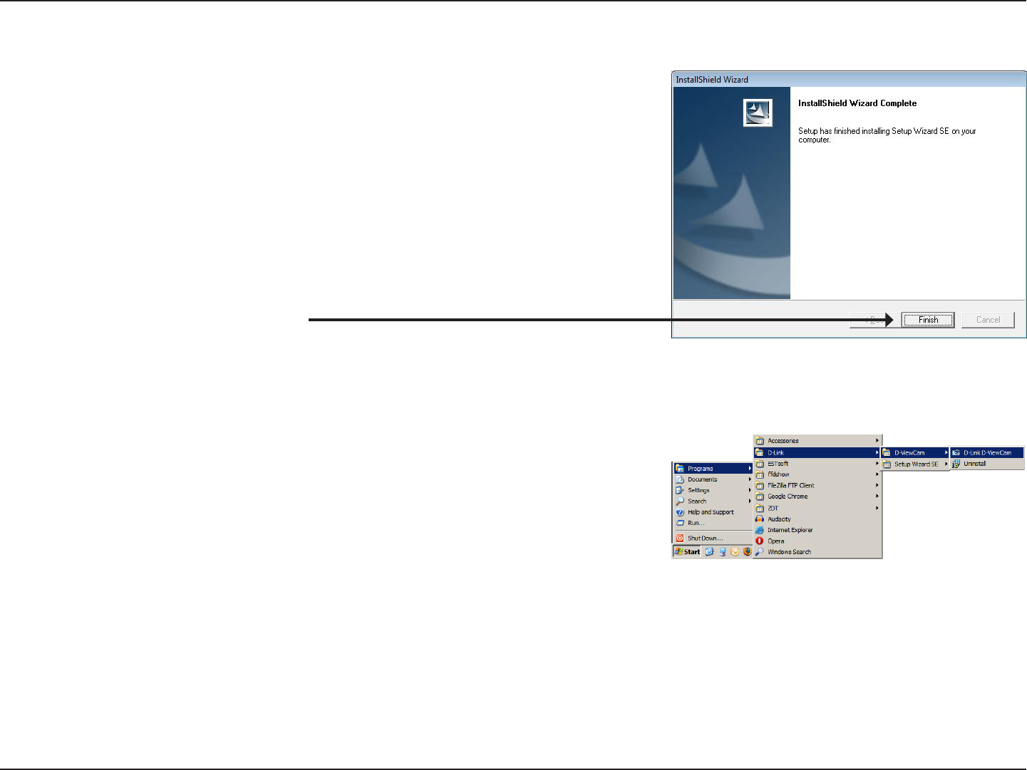
Click Finish to complete the installation.
Click on the D-Link Setup Wizard SE icon that was created in your Windows
Start menu.
Start > D-Link > Setup Wizard SE
11D-Link DCS-2210/2230 User Manual
Hardware Overview
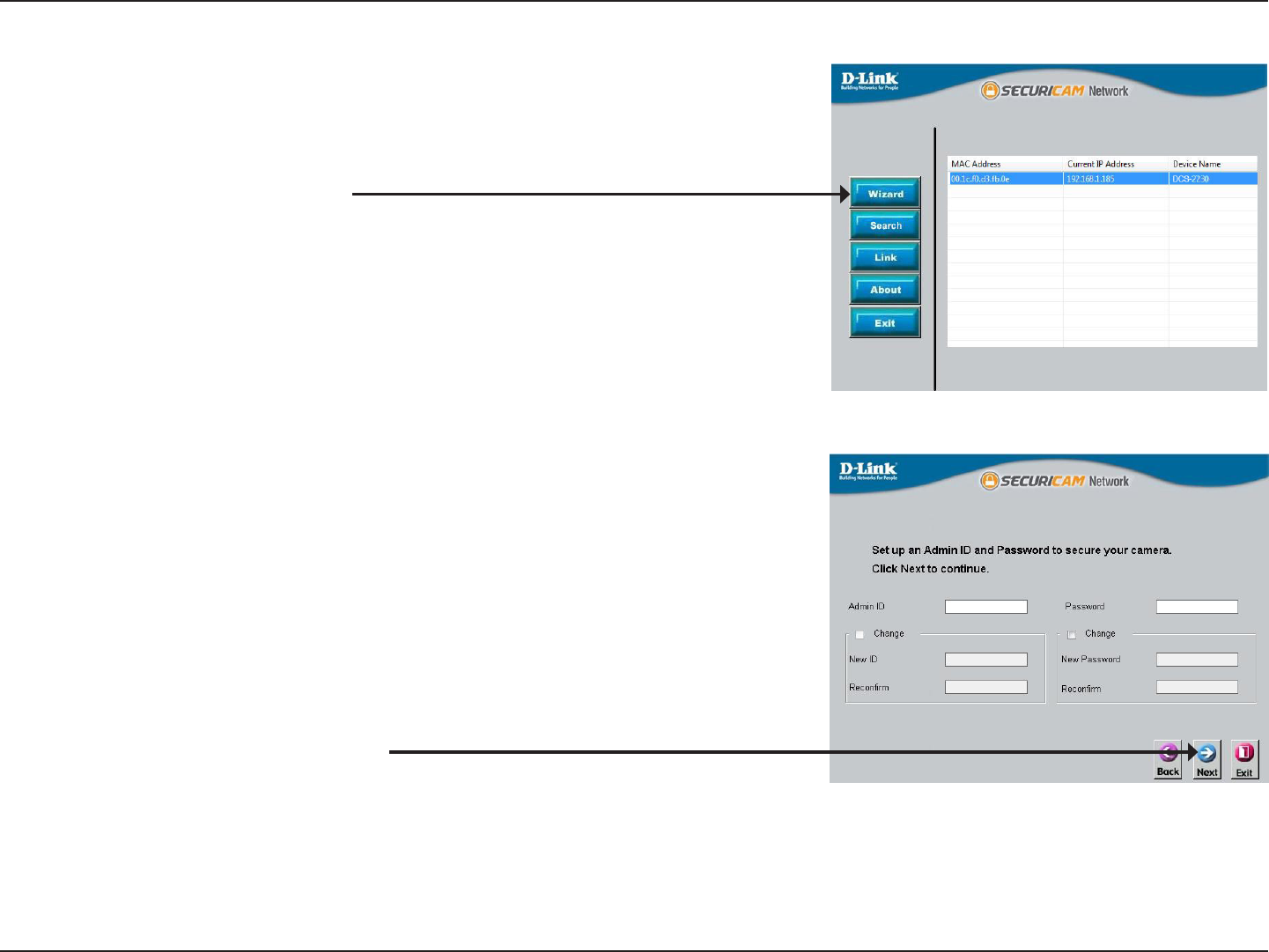
Enter the Admin ID and password. When logging in for the rst time, the default
Admin ID is admin with the password left blank.
Click Next, to proceed to the next page.
The Setup Wizard will appear and display the MAC address and IP address of
your camera(s). If you have a DHCP server on your network, a valid IP Address
will be displayed. If your network does not use a DHCP server, the network
camera's default static IP address 192.168.0.20 will be displayed.
Click the Wizard button to continue.
12D-Link DCS-2210/2230 User Manual
Hardware Overview
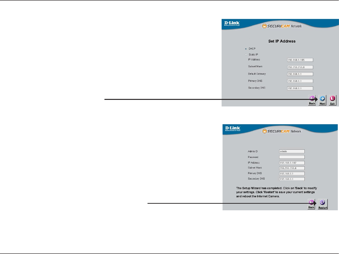
Take a moment to conrm your settings and click Restart.
Select DHCP if your camera obtains an IP address automatically when it boots up.
Select static IP if the camera will use the same IP address each time it is started.
Click Next, to proceed to the next page.
13D-Link DCS-2210/2230 User Manual
Conguration
Web-based Conguration Utility
Conguration
This section explains how to congure your new D-Link Network Camera using the Web-based Conguration Utility.
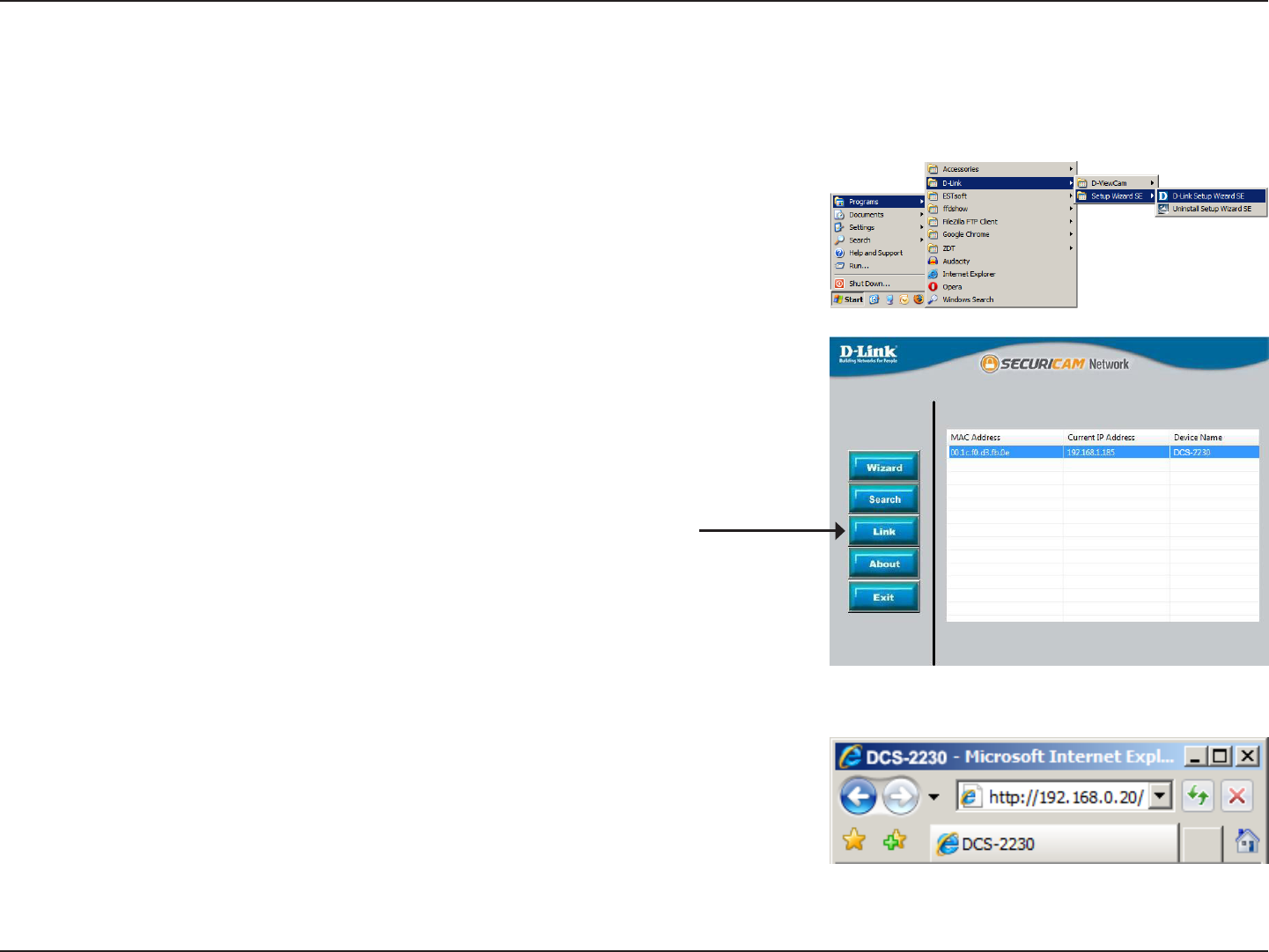
Click on the D-Link Setup Wizard SE icon that was created in your Windows
Start menu.
Start > D-Link > Setup Wizard SE
Select the camera and click the button labeled "Link" to access the web
conguration.
The Setup Wizard will automatically open your web browser to the IP address of
the camera.
Alternatively, you may manually open a browser and enter the IP address of the
camera: 192.168.0.20
14D-Link DCS-2210/2230 User Manual
Conguration
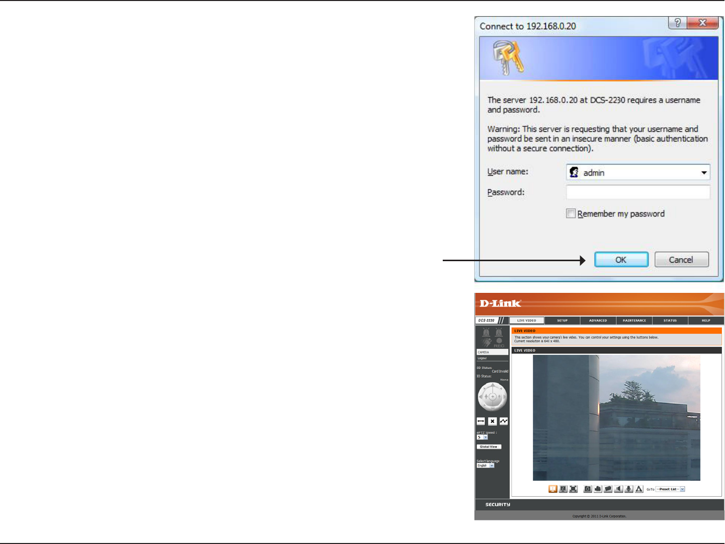
This section shows your camera’s live video. You can select your video prole and
view or operate the camera. For additional information about web conguration,
please refer to the user manual included on the CD-ROM or the D-Link website.
Enter admin as the default username and leave the password blank. Click OK to
continue.
15D-Link DCS-2210/2230 User Manual
Conguration
D-ViewCam Setup Wizard
D-ViewCam software is included for the administrator to manage multiple
D-Link IP cameras remotely. You may use the software to congure all
the advanced settings for your cameras. D-ViewCam is a comprehensive
management tool for IP surveillance.
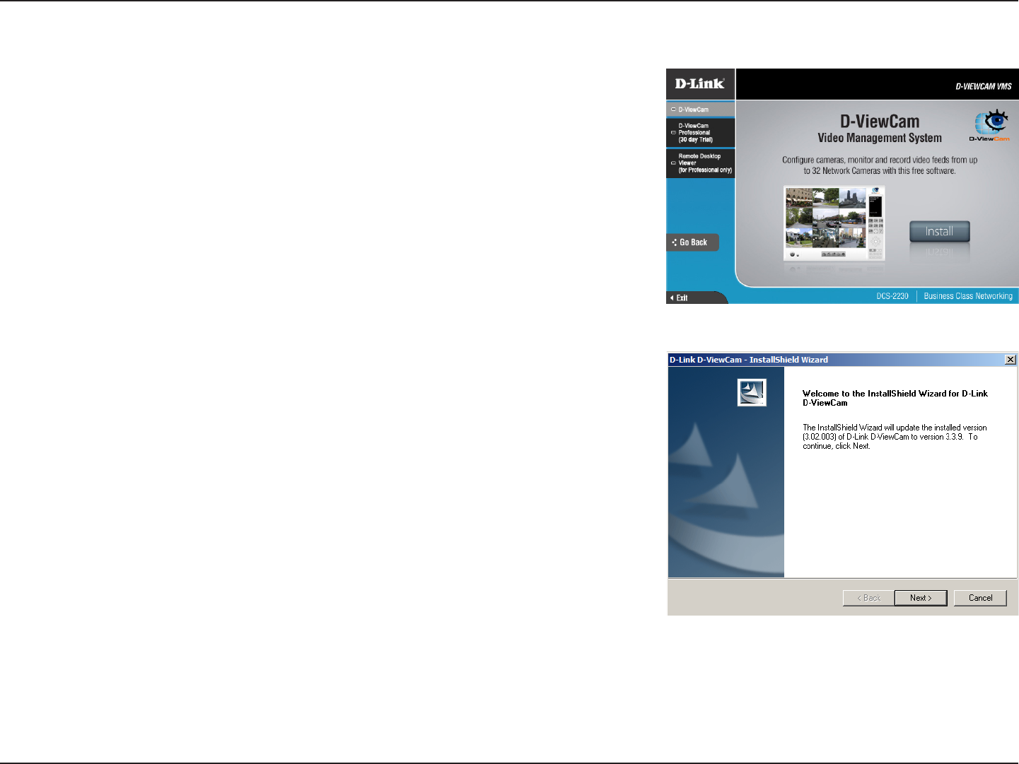
Insert the CD-ROM into the CD-ROM drive. Click "Install D-ViewCam
Software" from menu, and select "D-ViewCam" to install the VMS software.
Follow the Installation Wizard to install D-ViewCam.
16D-Link DCS-2210/2230 User Manual
Conguration
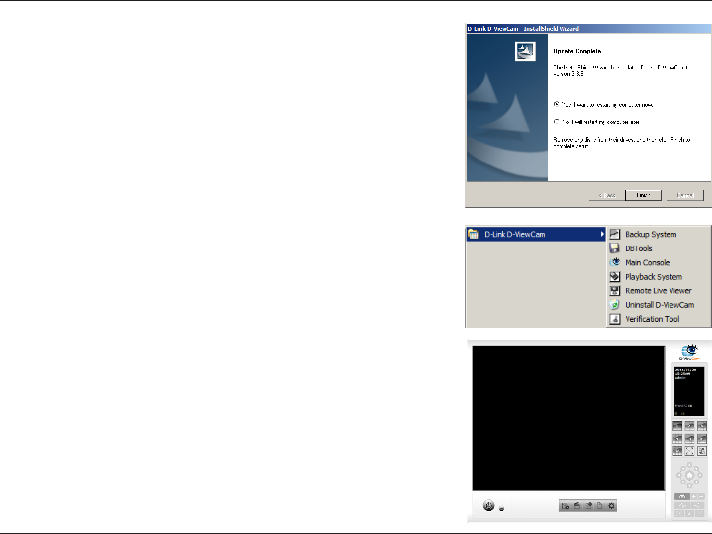
Click Finish to complete the installation.
To start D-ViewCam, select Start > All Programs > D-Link D-ViewCam >
Main Console.
For more detail operation of using D-ViewCam software, please refer to
D-ViewCam Manual.
17D-Link DCS-2210/2230 User Manual
Conguration
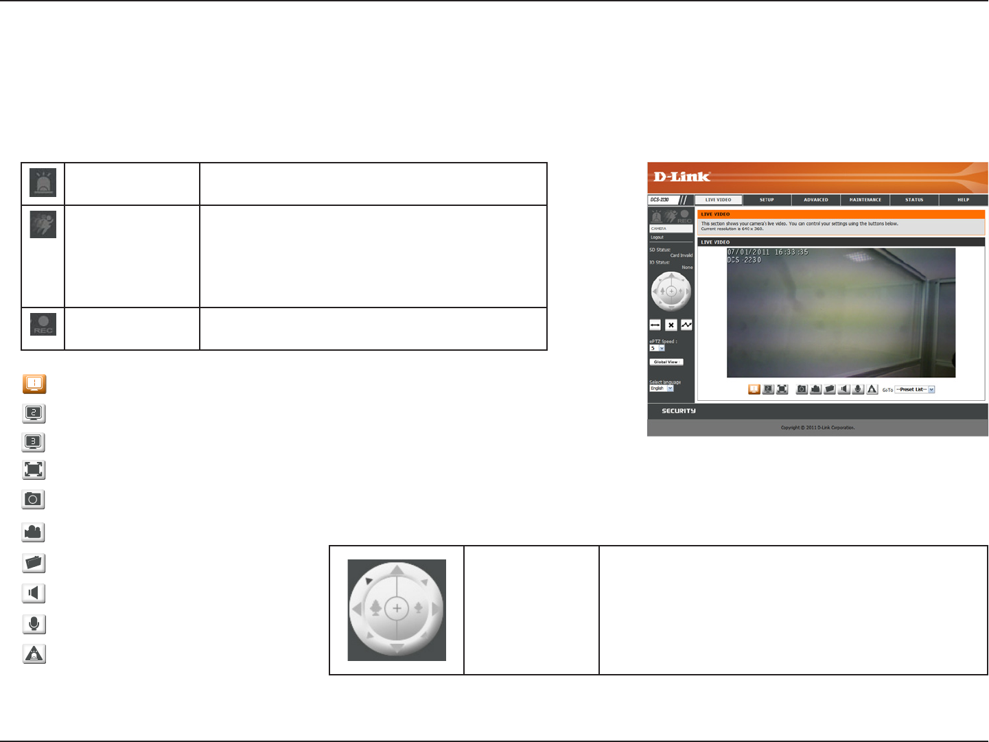
Live Video
This section shows your camera’s live video. You may select any of the available icons listed below to operate the camera. You may
also select your language using the drop-down menu on the left side of the screen.
You can zoom in and out on the live video image using your mouse. Right-click to zoom out or left-click to zoom in on the image.
Digital Input
Indicator
This indicator will change color when a digital
input signal is detected.
Motion Trigger
Indicator
This indicator will change color when a trigger
event occurs.
Note: The video motion feature for your
camera must be enabled.
Recording
Indicator
When a recording is in progress, this indicator
will change color.
Video Prole 1
Video Prole 2
Video Prole 3
Full screen mode
Taking a Snapshot
Recording a Video Clip
Set a Storage Folder
Listen/Stop Listening
Talk/Stop Talking
Start/Stop Digital Output
Control Pad
This control pad can be used to pan, tilt, and zoom
within the camera's predened view area, if one
has been dened.
18D-Link DCS-2210/2230 User Manual
Conguration
If any presets have been dened, selecting a preset from this list
will display it.
This option displays the status of the SD card. If no SD card has
been inserted, this screen will display the message "Card Invalid."
This option displays the status of your I/O device if a device has
been connected.
This camera uses electronic pan/tilt/zoom (ePTZ) to select and
view areas of interest in the eld of view. Please see page 32 for
information about setting the frame size and view window area.
You may select a value between 0 and 64. 0 is the slowest and 64
is the fastest.
This window indicates the total eld of view (FOV) of the camera.
The red box indicates the visible region of interest (ROI).
You may select the interface language using this menu.
Go To:
(Preset List)
SD Status:
IO Status:
PTZ Control:
ePTZ Speed:
Global View:
Language:
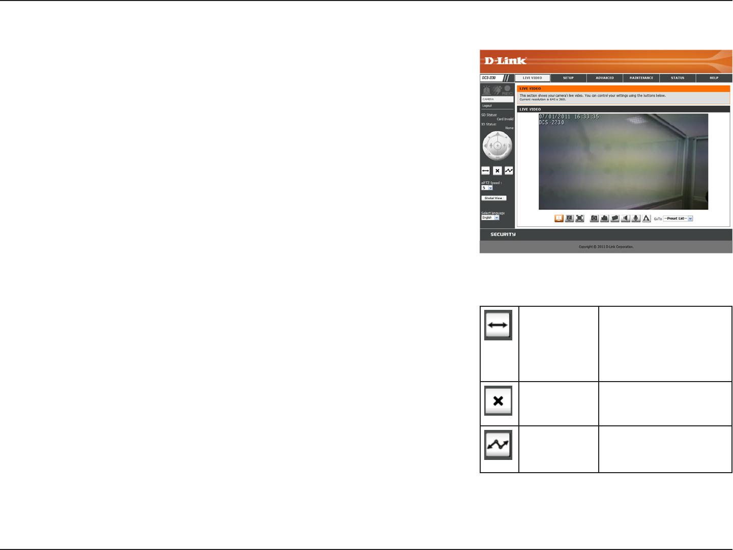
Auto Pan Starts the automatic
panning function. The
ROI will pan from back
and forth within the
FOV
Stop Stops the camera
ePTZ motion
Preset Path Starts the camera's
motion along the
predened path
19D-Link DCS-2210/2230 User Manual
Conguration
Setup
Wizard
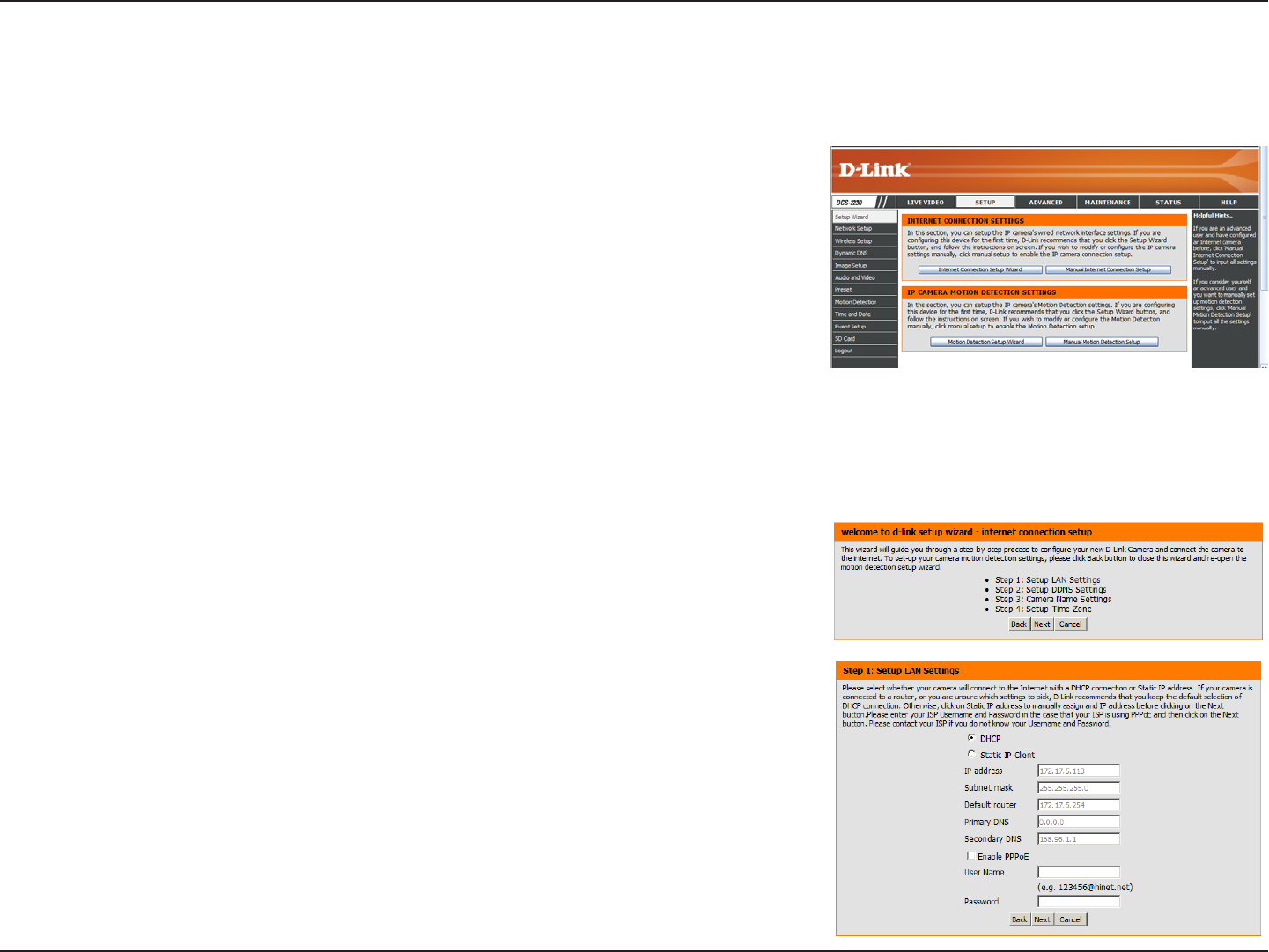
To congure your Network Camera, click Internet Connection
Setup Wizard. Alternatively, you may click Manual Internet
Connection Setup to manually congure your Network Camera and
skip to page 22.
To quickly congure your Network Camera’s motion detection
settings, click Motion Detection Setup Wizard. If you want to
enter your settings without running the wizard, click Manual Motion
Detection Setup and skip to page 27.
Internet Connection Setup Wizard
This wizard will guide you through a step-by-step process to
congure your new D-Link Camera and connect the camera to the
internet. Click Next to continue.
Note: Select DHCP if you are unsure of which settings to choose.
Click Next to continue.
20D-Link DCS-2210/2230 User Manual
Conguration
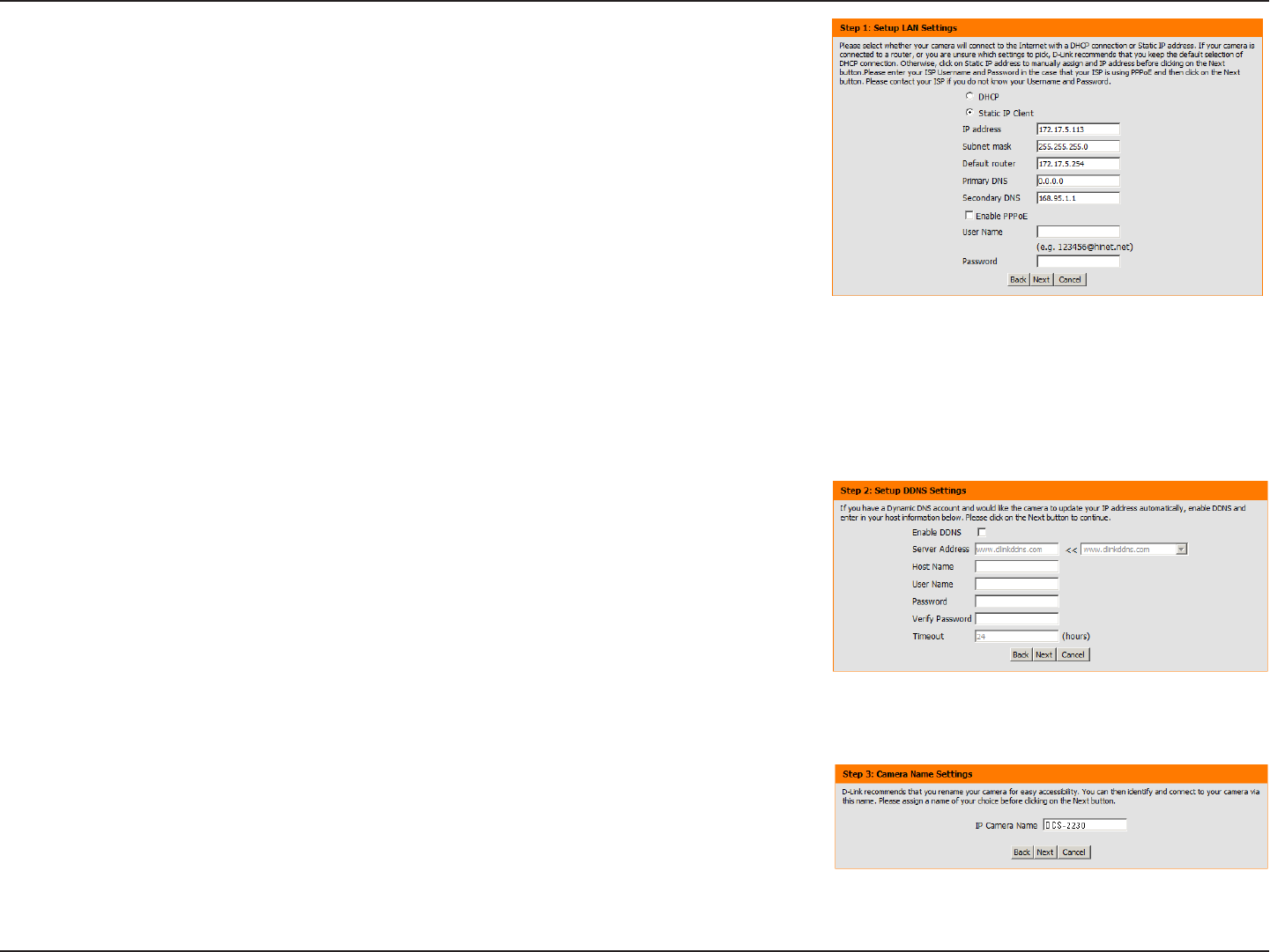
Select Static IP if your Internet Service Provider has provided you with
connection settings, or if you wish to set a static address within your
home network. Enter the correct conguration information and click Next
to continue.
If you are using PPPoE, select Enable PPPoE and enter your user name
and password, otherwise click Next to continue.
If you have a Dynamic DNS account and would like the camera to update
your IP address automatically, Select Enable DDNS and enter your host
information. Click Next to continue.
Enter a name for your camera and click Next to continue.
21D-Link DCS-2210/2230 User Manual
Conguration
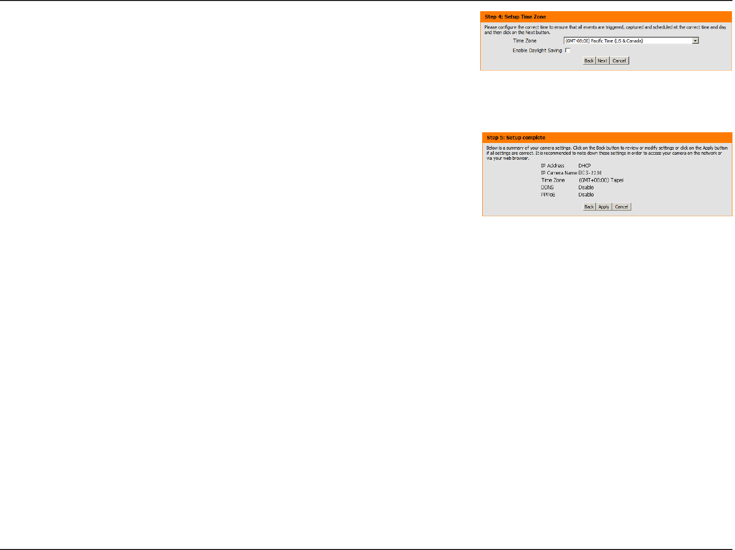
Congure the correct time to ensure that all events will be
triggered as scheduled. Click Next to continue.
If you have selected DHCP, you will see a summary of your
settings, including the camera's IP address. Please write down
all of this information as you will need it in order to access your
camera.
Click Apply to save your settings.
22D-Link DCS-2210/2230 User Manual
Conguration
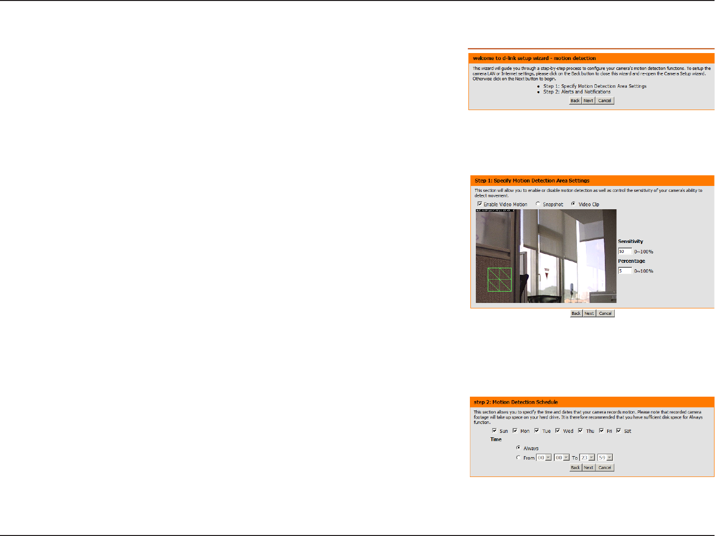
This wizard will guide you through a step-by-step process to congure your
camera's motion detection functions.
Click Next to continue.
Step 1
This step will allow you to enable or disable motion detection, specify the
detection sensitivity, and adjust the camera’s ability to detect movement.
You may specify whether the camera should capture a snapshot or a video
clip when motion is detected.
Please see the Motion Detection section on page 27 for information about
how to congure motion detection.
Step 2
This step allows you to enable motion detection based on a customized
schedule. Specify the day and hours. You may also choose to always
record motion.
Motion Detection Setup Wizard
23D-Link DCS-2210/2230 User Manual
Conguration
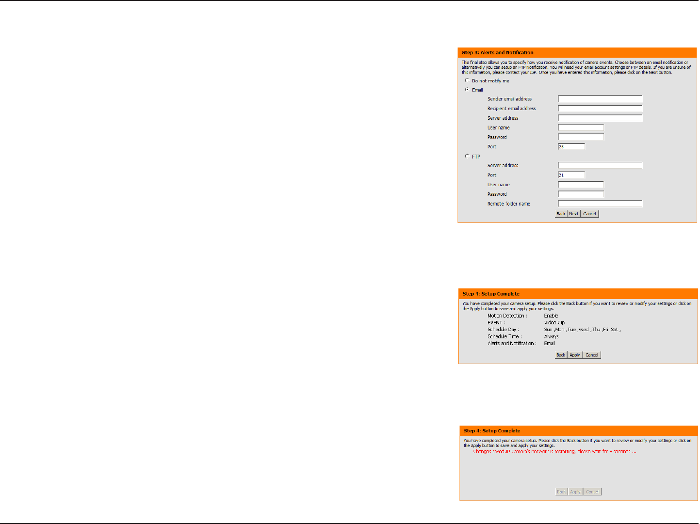
Step 3
This step allows you to specify how you will receive event notications
from your camera. You may choose not to receive notications, or to
receive notications via e-mail or FTP.
Please enter the relevant information for your e-mail or FTP account.
Click Next to continue.
Step 4
You have completed the Motion Detection Wizard.
Please verify your settings and click Apply to save them.
Please wait a few moments while the camera saves your settings and
restarts.
24D-Link DCS-2210/2230 User Manual
Conguration
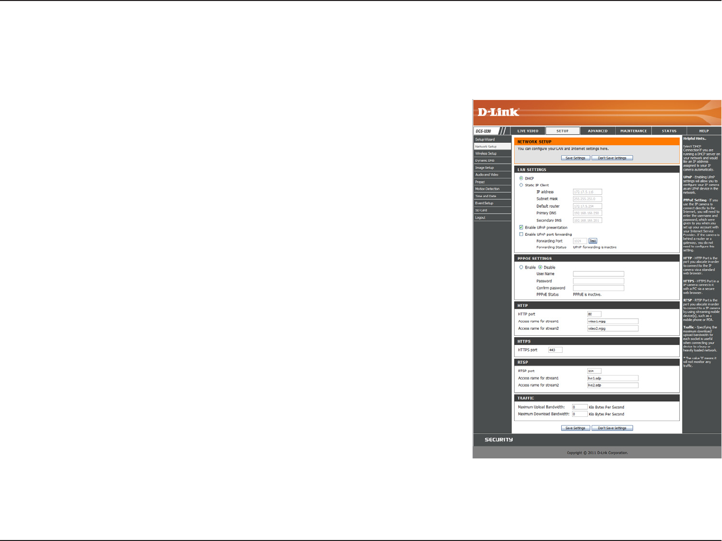
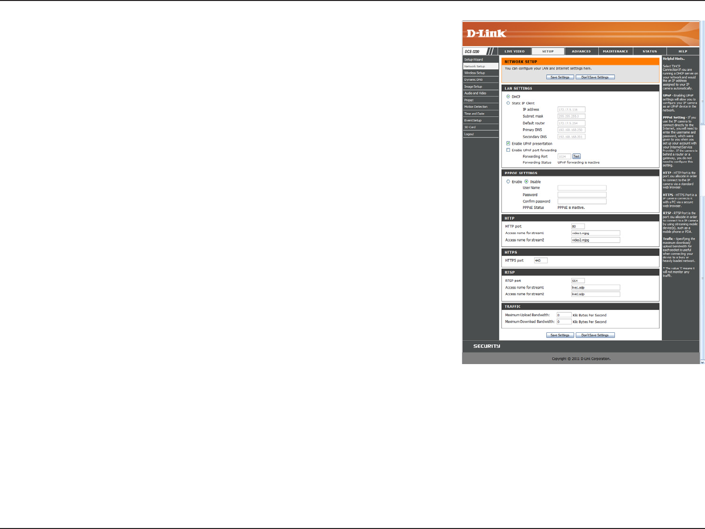
Network Setup
Use this section to congure the network connections for your camera. All relevant information must be entered accurately. After
making any changes, click the Save Settings button to save your changes.
LAN Settings:
DHCP:
Static IP Address:
IP Address:
Subnet Mask:
Default Gateway:
Primary DNS:
Secondary DNS:
This section lets you congure settings for your local
area network.
Select this connection if you have a DHCP server
running on your network and would like your camera
to obtain an IP address automatically.
You may obtain a static or xed IP address and
other network information from your network
administrator for your camera. A static IP address
may simplify access to your camera in the future.
Enter the xed IP address in this eld.
This number is used to determine if the destination
is in the same subnet. The default value is
255.255.255.0.
The gateway used to forward frames to destinations
in a different subnet. Invalid gateway settings may
cause the failure of transmissions to a different
subnet.
The primary domain name server translates names
to IP addresses.
The secondary DNS acts as a backup to the primary
DNS.
25D-Link DCS-2210/2230 User Manual
Conguration
Enable UPnP:
Enable UPnP Port Forwarding:
Enable PPPoE:
User Name / Password:
HTTP Port:
Access Name for Stream 1~3:
HTTPS Port:
RTSP Port:
Enabling this setting allows your camera to be
congured as a UPnP device on your network.
Enabling this setting allows the camera to add port
forwarding entries into the router automatically on a
UPnP capable network.
Enable this setting if your network uses PPPoE.
Enter the username and password for your PPPoE
account. Re-enter your password in the Conrm
Password eld. You may obtain this information
from your ISP.
The default port number is 80.
The default name is video#.mjpg, where # is the
number of the stream.
You may use a PC with a secure browser to
connect to the HTTPS port of the camera. The
default port number is 443.
The port number that you use for RTSP streaming
to mobile devices, such as mobile phones or PDAs.
The default port number is 554. You may specify the
address of a particular stream. For instance, live1.
sdp can be accessed at rtsp://x.x.x.x/video1.sdp
where the x.x.x.x represents the ip address of your
camera.

26D-Link DCS-2210/2230 User Manual
Conguration
Maximum Upload/Download
Bandwidth:
Specifying the maximum download/upload bandwidth
for each socket can be useful when connecting your
device to a busy or heavily loaded network. Entering
a value of '0' indicates that the camera should not
monitor bandwidth. Specifying other values will limit
the camera's transfer speed to the specied number
of kilobytes per second.
27D-Link DCS-2210/2230 User Manual
Conguration
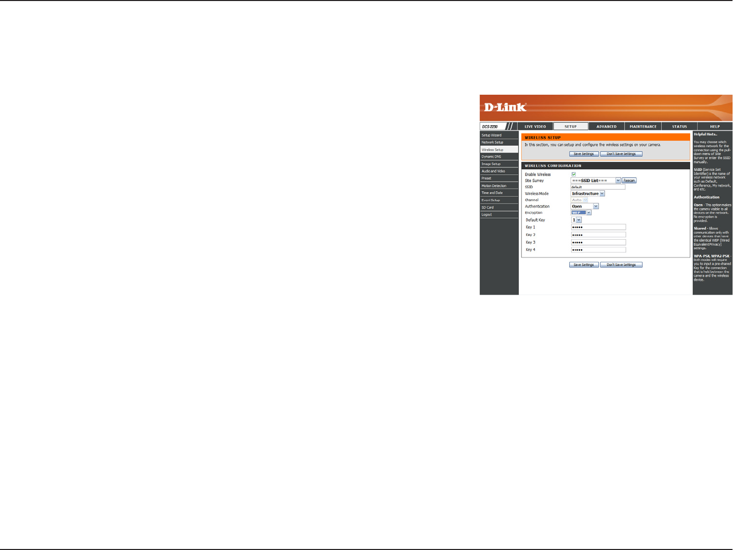
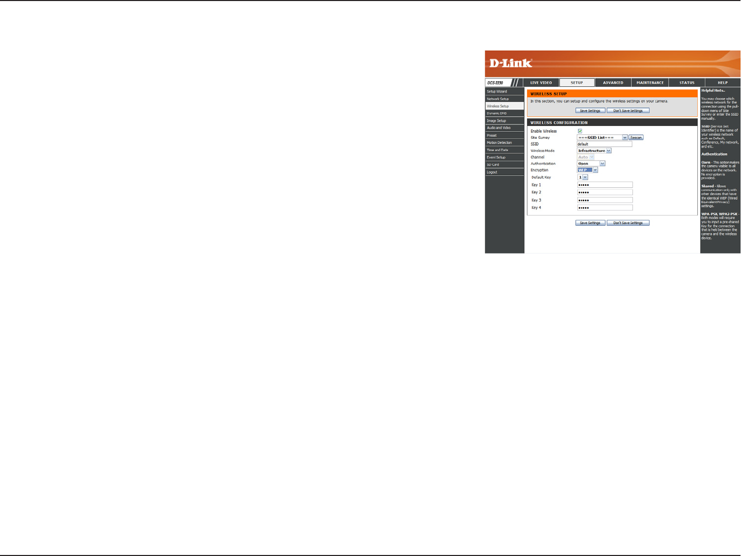
Wireless Setup(DCS-2230 only)
This section allows you to set up and congure the wireless settings on your camera. After making any changes, click the Save
Settings button to save your changes.
Site Survey:
SSID:
Wireless Mode:
Channel:
Authentication:
Encryption:
Click the Rescan button to scan for available wireless
networks. After scanning, you can use the dropdown
box to select an available wireless network. The
related information (SSID, Wireless Mode, Channel,
Authentication, Encryption) will be automatically
lled in for you.
Enter the SSID of the wireless access point you
wish to use.
Use the dropdown box to select the mode of the
wireless network you wish to connect to.
Infrastructure is normally used to connect to an
access point or router. Ad-Hoc is usually used to
connect directly to another computer.
If you are using Ad Hoc mode, select the channel
of the wireless network you wish to connect to, or
select Auto.
Select the authentication you use on your wireless
network - Open, Shared, WPA-PSK, or WPA2-PSK.
If you use WPA-PSK or WPA2-PSK authentication,
you will need to specify whether your wireless
network uses TKIP or AES encryption. If you use
Open or Shared authentication, WEP encryption
should be setting.
28D-Link DCS-2210/2230 User Manual
Conguration
Key: If you use WEP, WPA-PSK, or WPA2-PSK
authentication, enter the Key (also known as
password) used for your wireless network.
29D-Link DCS-2210/2230 User Manual
Conguration
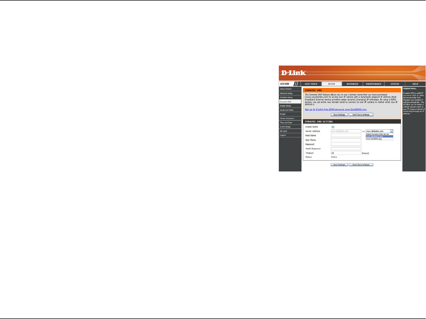
Dynamic DNS
DDNS (Dynamic Domain Name Server) will hold a DNS host name and synchronize the public IP address of the modem when it has
been modied. A user name and password are required when using the DDNS service. After making any changes, click the Save
Settings button to save your changes.
Enable DDNS:
Server Address:
Host Name:
User Name:
Password:
Timeout:
Status:
Select this checkbox to enable the DDNS function.
Select your Dynamic DNS provider from the pull
down menu or enter the server address manually.
Enter the host name of the DDNS server.
Enter the user name or e-mail used to connect to
your DDNS account.
Enter the password used to connect to your DDNS
server account.
Enter the DNS Timeout values you wish to use.
Indicates the connection status, which is
automatically determined by the system.
30D-Link DCS-2210/2230 User Manual
Conguration
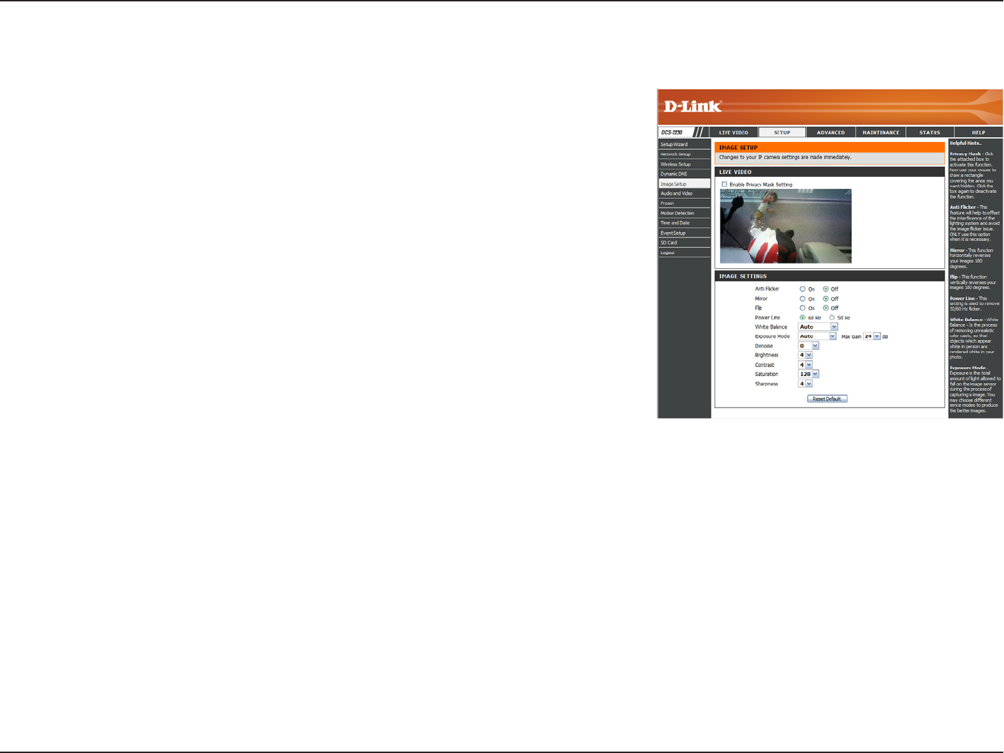
Image Setup
In this section, you may congure the video image settings for your camera. A preview of the image will be shown in Live Video.
Enable Privacy
Mask:
Anti Flicker:
Mirror:
Flip:
Power Line:
White Balance:
Exposure
Mode:
Denoise:
Brightness:
The Privacy Mask setting allows you to specify upto 3 rectangular areas
on the camera's image to beblocked/excluded from recordings and
snapshots.
You may click and drag the mouse cursor over thecamera image to draw
a mask area.Right clicking on the camera image brings up thefollowing
menu options:
Disable All: Disables all mask areas
Enable All: Enables all mask areas
Reset All: Clears all mask areas.
If the video ickers, try enabling this setting.
This will mirror the image horizontally.
This will ip the image vertically. When turning Flip on, you may want to
consider turning Mirror on as well.
Select the frequency used by your power lines to avoid interference or
distortion.
Use the dropdown box to change white balance settings to help balance colors for different environments. You can choose
from Auto, Outdoor, Indoor, Fluorescent, and Push Hold.
Changes the exposure mode. Use the dropdown box to set the camera for Indoor, Outdoor, or Night environments, or to
Moving to capture moving objects. The Low_Noise option will focus on creating a high-quality picture without noise. You can
also create 3 different custom exposure modes. The Max Gain setting will allow you to control the maximum amount of gain
to apply to brighten the picture.
This setting controls the amount of noise reduction that will be applied to the picture.
Adjust this setting to compensate for backlit subjects.

31D-Link DCS-2210/2230 User Manual
Conguration
Contrast:
Saturation:
Sharpness:
Reset Default:
Adjust this setting to alter the color intensity/strength.
This setting controls the amount of coloration, from grayscale to fully saturated.
Specify a value from 0 to 8 to specify how much sharpening to apply to the image.
Click this button to reset the image to factory default settings.
32D-Link DCS-2210/2230 User Manual
Conguration
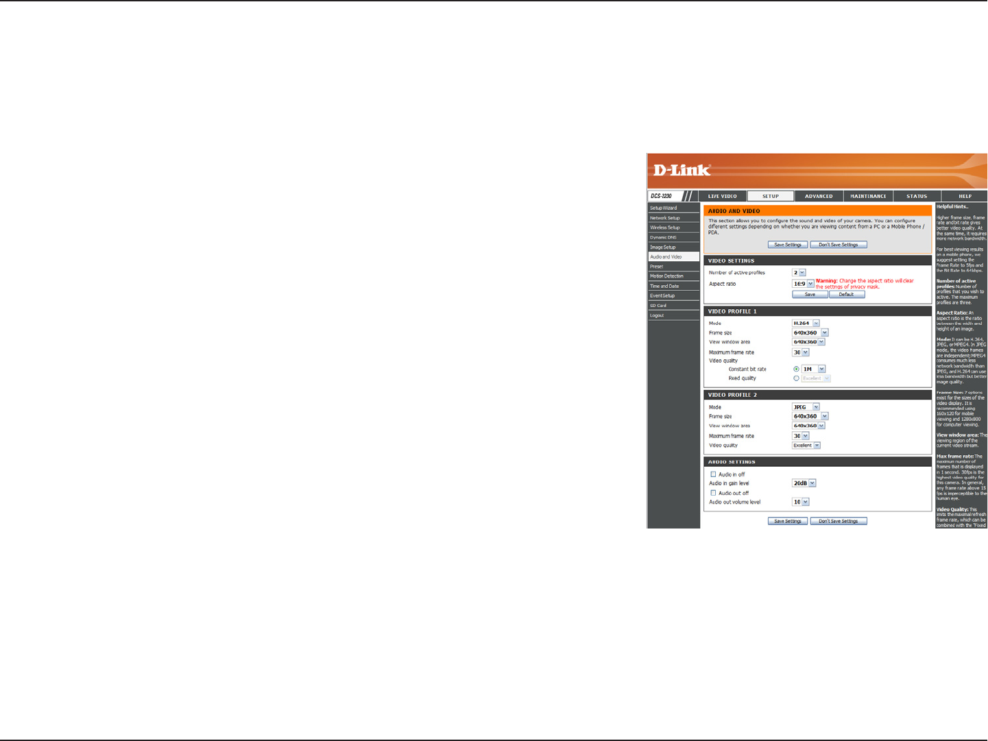
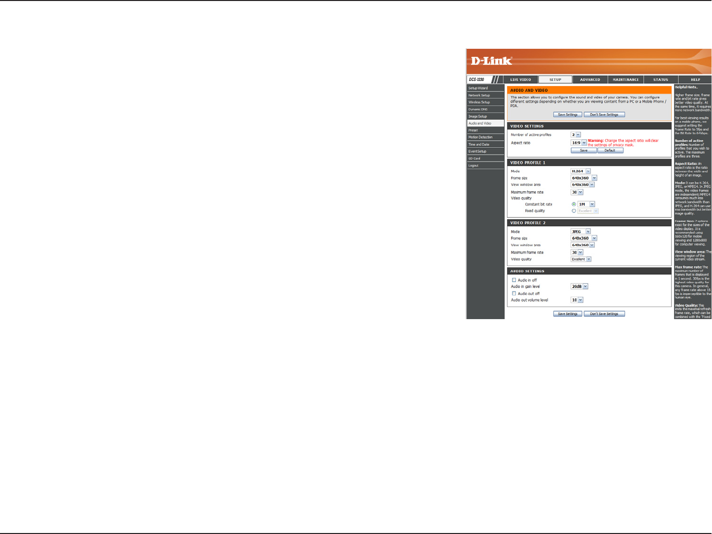
Audio and Video
You may congure up to 3 video proles with different settings for your camera. Hence, you may set up different proles for your
computer and mobile display. In addition, you may also congure the two-way audio settings for your camera. After making any
changes, click the Save Settings button to save your changes.
Number of active proles:
Aspect ratio:
Mode:
Frame size / View window
area:
Maximum frame rate:
You can use the dropdown box to set up to 3 active
proles.
Set the aspect ratio of the video to 4:3 standard or
16:9 widescreen.
Set the video codec to be used to JPEG, MPEG-4,
or H.264.
Frame size determines the total capture resolution,
and View window area determines the Live Video
viewing window size. If the Frame size is larger than
the Live Video size, you can use the ePTZ controls
to look around.
16:9 1920x1080, 1280x720, 800x450,
640x360, 480x270, 320x176, 176x144
4:3 1024x768, 800x600, 640x480, 480x 360,
320x240, 176x144
Note: If your View window area is the same as your
Frame size, you will not be able to use the ePTZ
function.
A higher frame rate provides smoother motion for
videos, and requires more bandwidth. Lower frame
rates will result in stuttering motion, and requires
less bandwidth.
33D-Link DCS-2210/2230 User Manual
Conguration
Video Quality:
Constant bit rate:
Fixed quality:
Audio in off:
Audio in gain level:
Audio out off:
Audio out volume level:
This limits the maximum frame rate, which can be
combined with the "Fixed quality" option to optimize
the bandwidth utilization and video quality. If xed
bandwidth utilization is desired regardless of the
video quality, choose "Constant bit rate" and select
the desired bandwidth.
The bps will affect the bit rate of the video recorded
by the camera. Higher bit rates result in higher
video quality.
Select the image quality level for the camera to
try to maintain. High quality levels will result in
increased bit rates.
Ticking this checkbox will mute incoming audio.
This setting controls the amount of gain applied to
incoming audio to increase its volume.
Ticking this checkbox will mute outgoing audio.
This setting controls the amount of gain applied to
outgoing audio to increase its volume.
34D-Link DCS-2210/2230 User Manual
Conguration
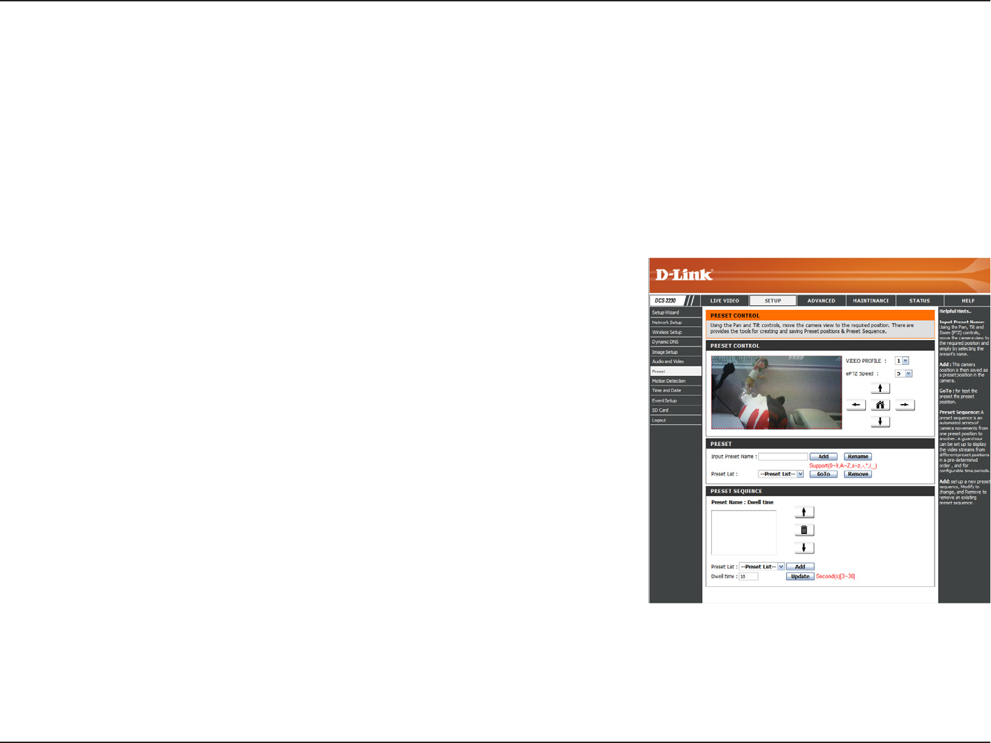
Preset
This screen allows you to set preset points for the ePTZ function of the camera, which allows you to look around the camera's viewable
area by using a zoomed view. Presets allow you to quickly go to and view a specic part of the area your camera is covering, and you
can create preset sequences, which will automatically change the camera's view between the different presets according to a dened
order and timing you can set.
Note: If your View window area is the same as your Frame size, you will not be able to use the ePTZ function. For more details, refer to
"Audio and Video" on page 32.
Video Prole:
ePTZ Speed:
Arrow Buttons and Home
Button:
Input Preset Name:
Preset List:
This selects which video prole to use. For more
information, refer to "Audio and Video" on page 32.
Select your Dynamic DNS provider from the pull
down menu or enter the server address manually.
Use these buttons to move to a specic part of the
viewing area, which you can then set as a preset.
Click the Home button to return to the center of the
viewing area.
Enter the name of the preset you want to create,
then click the Add button to make a new preset.
If an existing preset has been selected from the
Preset List, you can change its name by typing in a
new name, then clicking the Rename button.
Click this dropdown box to see a list of all the
presets that have been created. You can select one,
then click the GoTo button to change the displayed
camera view to the preset. Clicking the Remove
button will delete the currently selected preset.
35D-Link DCS-2210/2230 User Manual
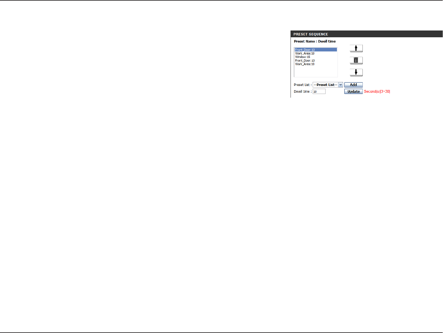
Conguration
Preset Sequence: This section allows you to create a preset
sequence, which automatically moves the camera's
view between a set of preset views.
To add a preset to the sequence, select it from the
dropdown box at the bottom of this window, set the
Dwell time to determine how long the camera view
will stay at that preset, then click the Add button.
The preset name will appear in the list, followed by
the dwell time to view that preset for.
You can rearrange your presets in the sequence
by selecting a preset in the sequence, then clicking
the arrow buttons to move it higher or lower in the
current sequence.
Clicking the trash can button will remove the
currently selected preset from the sequence.
If you want to change the dwell time for a preset,
select it from the list, enter a new dwell time, then
click the Update button.
36D-Link DCS-2210/2230 User Manual
Conguration
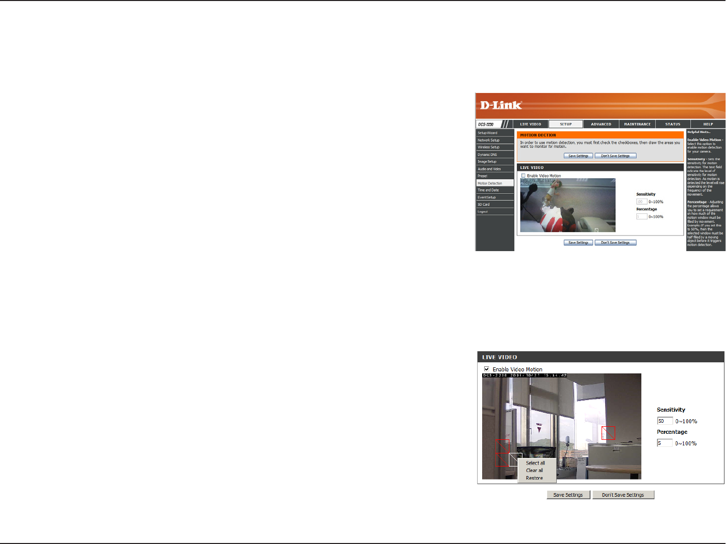
Motion Detection
Enabling Video Motion will allow your camera to use the motion detection feature. You may draw a nite motion area that will be used
for monitoring. After making any changes, click the Save Settings button to save your changes.
Enable Video Motion:
Sensitivity:
Percentage:
Draw Motion Area:
Erase Motion Area:
Select this box to enable the motion detection
feature of your camera.
Species the measurable difference between two
sequential images that would indicate motion. Please
enter a value between 0 and 100.
Species the amount of motion in the window being
monitored that is required to initiate an alert. If this
is set to 100%, motion is detected within the whole
window will trigger a snapshot.
Draw the motion detection area by dragging your
mouse in the window (indicated by the red square).
To erase a motion detection area, simply click on the
red square that you wish to remove.
Right clicking on the camera image brings up the
following menu options:
Select All: Draws a motion detection area over
the entire screen.
Clear All: Clears any motion detection areas that
have been drawn.
Restore: Restores the previously specied motion
detection areas.
37D-Link DCS-2210/2230 User Manual
Conguration
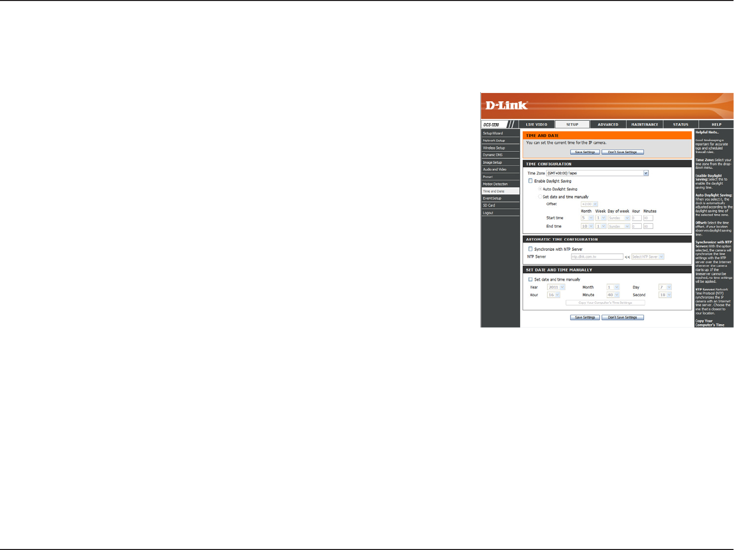
Time and Date
This section allows you to automatically or manually congure, update, and maintain the internal system clock for your camera. After
making any changes, click the Save Settings button to save your changes.
Time Zone:
Enable Daylight Saving:
Auto Daylight Saving:
Set Date and Time Manually:
Offset:
Synchronize with NTP Server:
NTP Server:
Set the Date and Time
Manually:
Copy Your Computer's Time
Settings:
Select your time zone from the drop-down menu.
Select this to enable Daylight Saving Time.
Select this option to allow your camera to congure
the Daylight Saving settings automatically.
Selecting this option allows you to congure the
Daylight Saving date and time manually.
Sets the amount of time to be added or removed
when Daylight Saving is enabled.
Enable this feature to obtain time automatically from
an NTP server.
Network Time Protocol (NTP) synchronizes the
DCS-2230 with an Internet time server. Choose the
one that is closest to your location.
This option allows you to set the time and date
manually.
This will synchronize the time information from your
PC.
38D-Link DCS-2210/2230 User Manual
Conguration
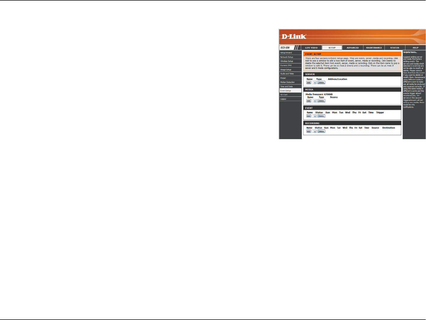
Event Setup
The Event Setup page includes 4 different sections.
• Event
• Server
• Media
• Recording
1. To add a new item - "event, server or media," click Add. A screen will appear and
allow you to update the elds accordingly.
2. To delete the selected item from the pull-down menu of event, server or media, click
Delete.
3. Click on the item name to pop up a window for modifying.
Note: You can add up to four events, ve servers, and ve media elds.
39D-Link DCS-2210/2230 User Manual
Conguration
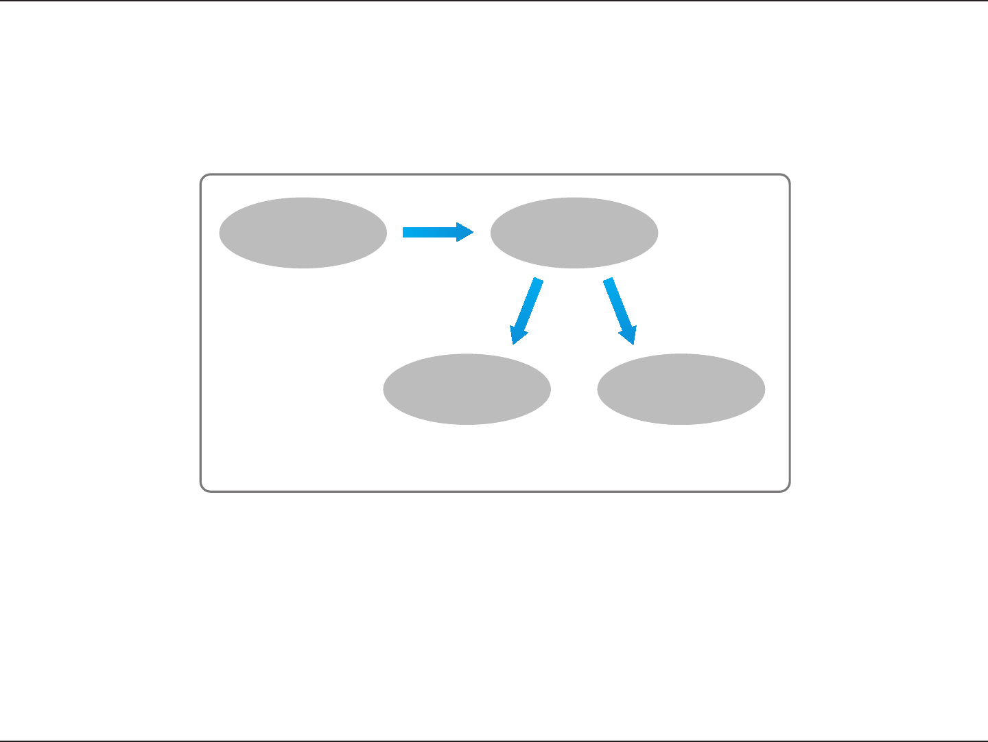
Application
In a typical application, when motion is detected, the DCS-2230 Network Camera sends images to a FTP server or via e-mail as
notications. As shown in the illustration below, an event can be triggered by many sources, such as motion detection or external
digital input devices. When an event is triggered, a specied action will be performed. You can congure the Network Camera to send
snapshots or videos to your e-mail address or FTP site.
ex.
Motion detection,
Periodically, Digital input,
System reboot
Event Condition
ex.
Snapshot, Video Clips
ex.
Email, FTP
Media
(what to send)
Server
(where to send)
Action
To start plotting an event, it is suggested to congure server and media columns rst so that the Network Camera will know what action
shall be performed when a trigger is activated.
40D-Link DCS-2210/2230 User Manual
Conguration
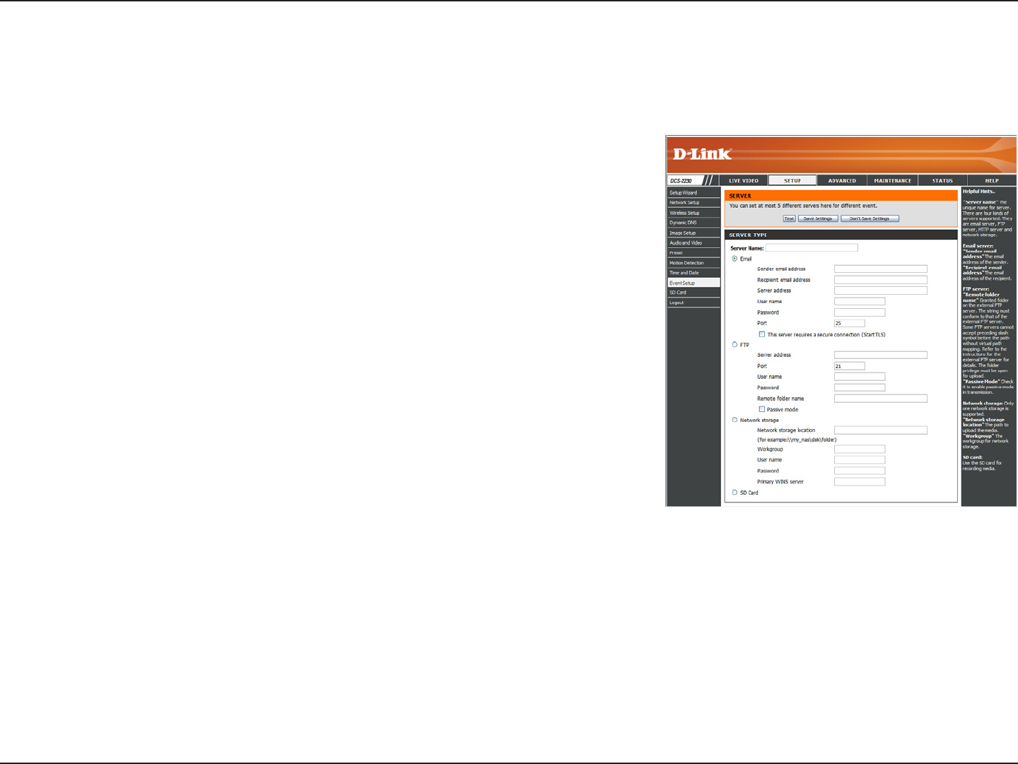
Add Server
Server Name:
E-mail:
FTP:
Network Storage:
SD Card:
Enter the unique name of your server.
Enter the conguration for the target e-mail server
account.
Enter the conguration for the target FTP server
account.
Specify a network storage device. Only one network
storage device is supported.
Use the camera's onboard SD card storage.
You can congure up to 5 servers to save snapshots and/or video to. After making any changes, click the Save Settings button to save
your changes.
41D-Link DCS-2210/2230 User Manual
Conguration
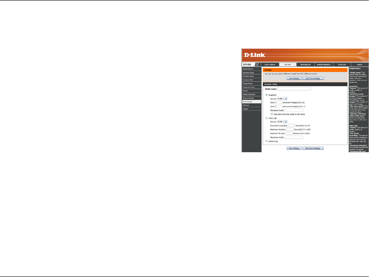
Add Media
Media Name:
Snapshot:
Source:
Send pre-event image(s) [0~4]:
Send post-event image(s)
[0~7]:
File name prex:
Add date and time sufx to le
name:
Enter an unique name for media type you want to
create.
Select this option to set the media type to snapshots.
Set the video prole to use as the media source.
Refer to "Audio and Video" on page 32 for more
information on video proles.
Set the number of pre-event images to take. Pre-
event images are images taken before the main
event snapshot is taken.
Set the number of post-event images to take. Post-
event images are images taken after the main event
snapshot is taken. You can set up to 7 post-event
images to be taken.
The prex name will be added on the le name.
Check it to add timing information as le name sufx.
There are three types of media, Snapshot, Video Clip, and System Log. After making any changes, click the Save Settings button to
save your changes.

42D-Link DCS-2210/2230 User Manual
Conguration
Video clip:
Source:
Pre-event recording:
Maximum duration:
Maximum le size:
File name prex:
System log:
Select this option to set the media type to video clips.
Set the video prole to use as the media source.
Refer to "Audio and Video" on page 32 for more
information on video proles.
This sets how many seconds to record before the
main event video clip starts. You can record up to 4
seconds of pre-event video.
Set the maximum length of video to record for your
video clips.
Set the maximum le size to record for your video
clips.
This is the prex that will be added to the lename
of saved video clips.
Select this option to set the media type to system
logs. This will save the event to the camera system
log, but will not record any snapshots or video.
43D-Link DCS-2210/2230 User Manual
Conguration
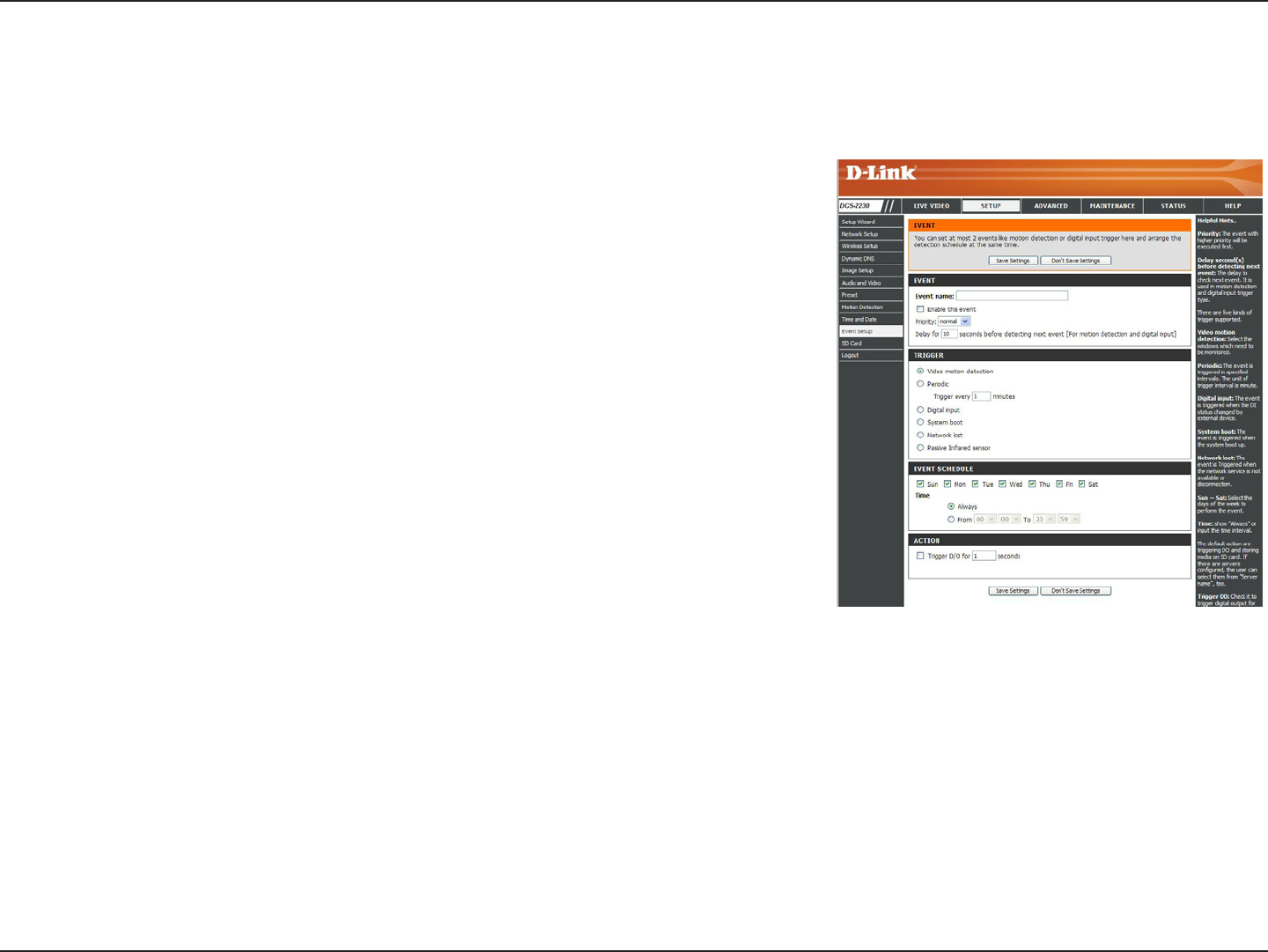
Add Event
Create and schedule up to 3 events with their own settings here. After making any changes, click the Save Settings button to save
your changes.
Event name:
Enable this event:
Priority:
Delay:
Trigger:
Video Motion Detection:
Periodic:
Digital input:
System Boot:
Network Lost:
Passive Infrared:
Enter a name for the event.
Select this box to activate this event.
Set the priority for this event. The event with higher
priority will be executed rst.
Select the delay time before checking the next event.
It is being used for both events of motion detection
and digital input trigger.
Specify the input type that triggers the event.
Motion is detected during live video monitoring.
Select the windows that need to be monitored.
The event is triggered in specied intervals. The
trigger interval unit is in minutes.
The external trigger input to the camera.
Triggers an event when the system boots up.
Triggers an event when if the network connection is
lost.
Triggers an event when the PIR sensor is activated
by moving infrared objects even in dark environment.
44D-Link DCS-2210/2230 User Manual
Conguration
Time:
Trigger D/O:
Server:
Select Always or enter the time interval.
Select to trigger the digital output for a specic
number of seconds when an event occurs.
Specify the location where the event information
should be saved to.
45D-Link DCS-2210/2230 User Manual
Conguration
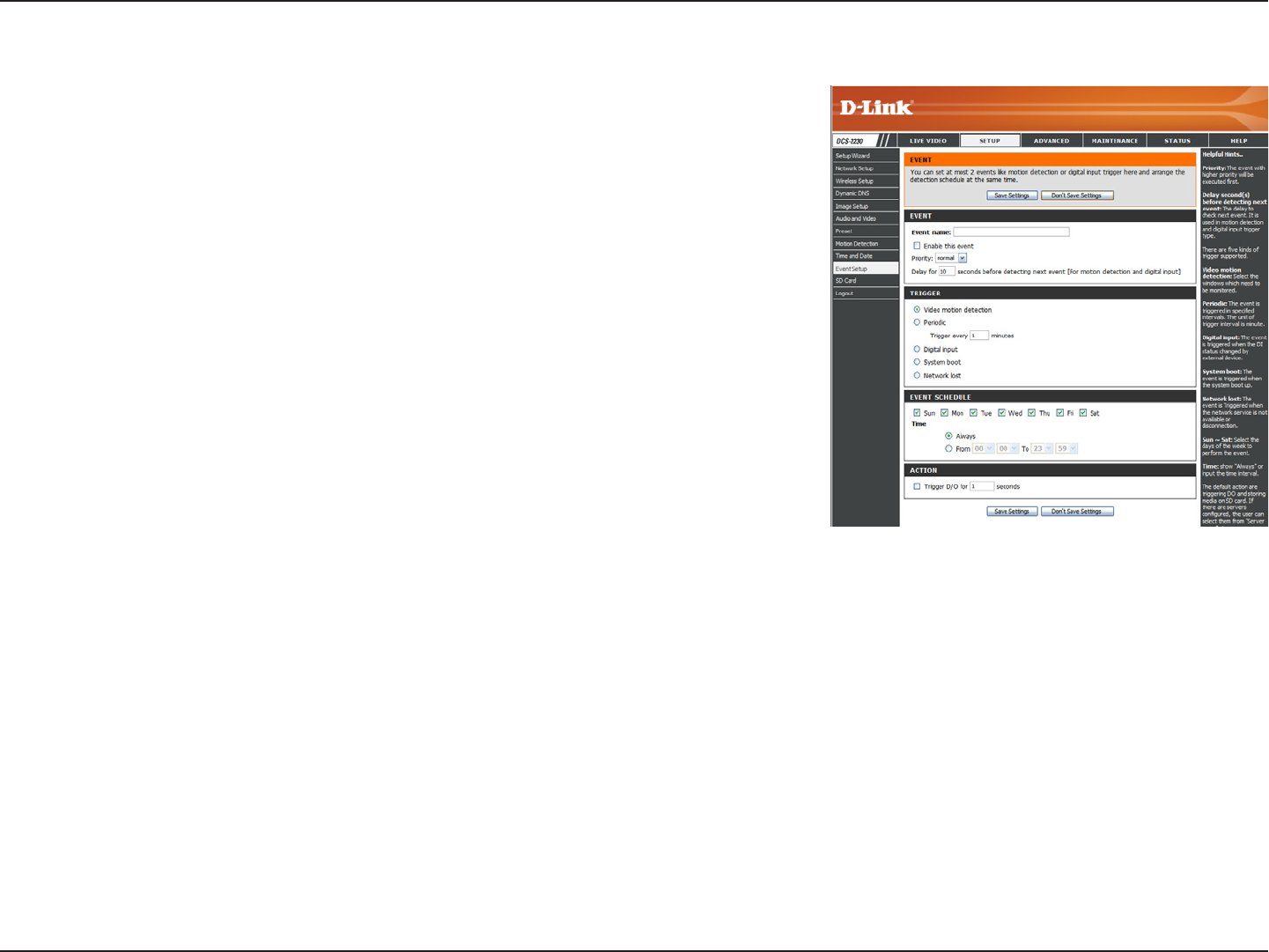
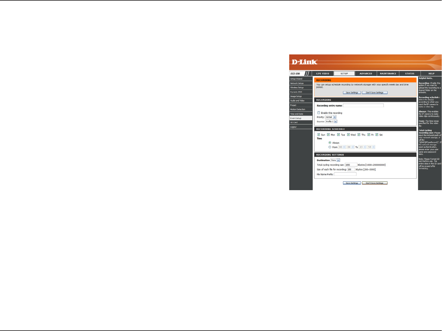
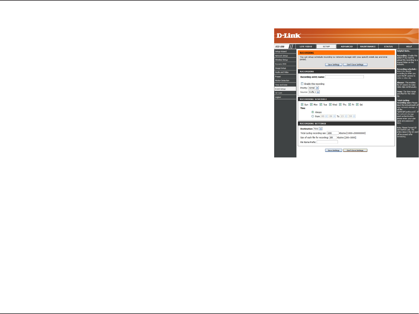
Add Recording
Recording entry name:
Enable this recording:
Priority:
Source:
Recording schedule:
Recording settings:
Destination:
Total cycling recording size:
The unique name of the entry.
Select this to enable the recording function.
Set the priority for this entry. The entry with a higher
priority value will be executed rst.
The source of the stream.
Scheduling the recording entry.
Conguring the setting for the recording.
Select the folder where the recording le will be
stored.
Please input a HDD volume between 1MB and
200GB for recording space. The recording data will
replace the oldest record when the total recording
size exceeds this value. For example, if each
recording le is 6MB, and the total cyclic recording
size is 600MB, then the camera will record 100 les
in the specied location (folder) and then will delete
the oldest le and create new le for cyclic recording.
Please note that if the free HDD space is not enough,
the recording will stop. Before you set up this option
please make sure your HDD has enough space, and
it is better to not save other les in the same folder
as recording les.
Here you can congure and schedule the recording settings. After making any changes, click the Save Settings button to save your
changes.
46D-Link DCS-2210/2230 User Manual
Conguration
Size of each le for recording:
File Name Prex:
File size for each recording le. You may input the
value in the range of 200-5000.
The prex name will be added on the le name of
the recording le(s).
47D-Link DCS-2210/2230 User Manual
Conguration
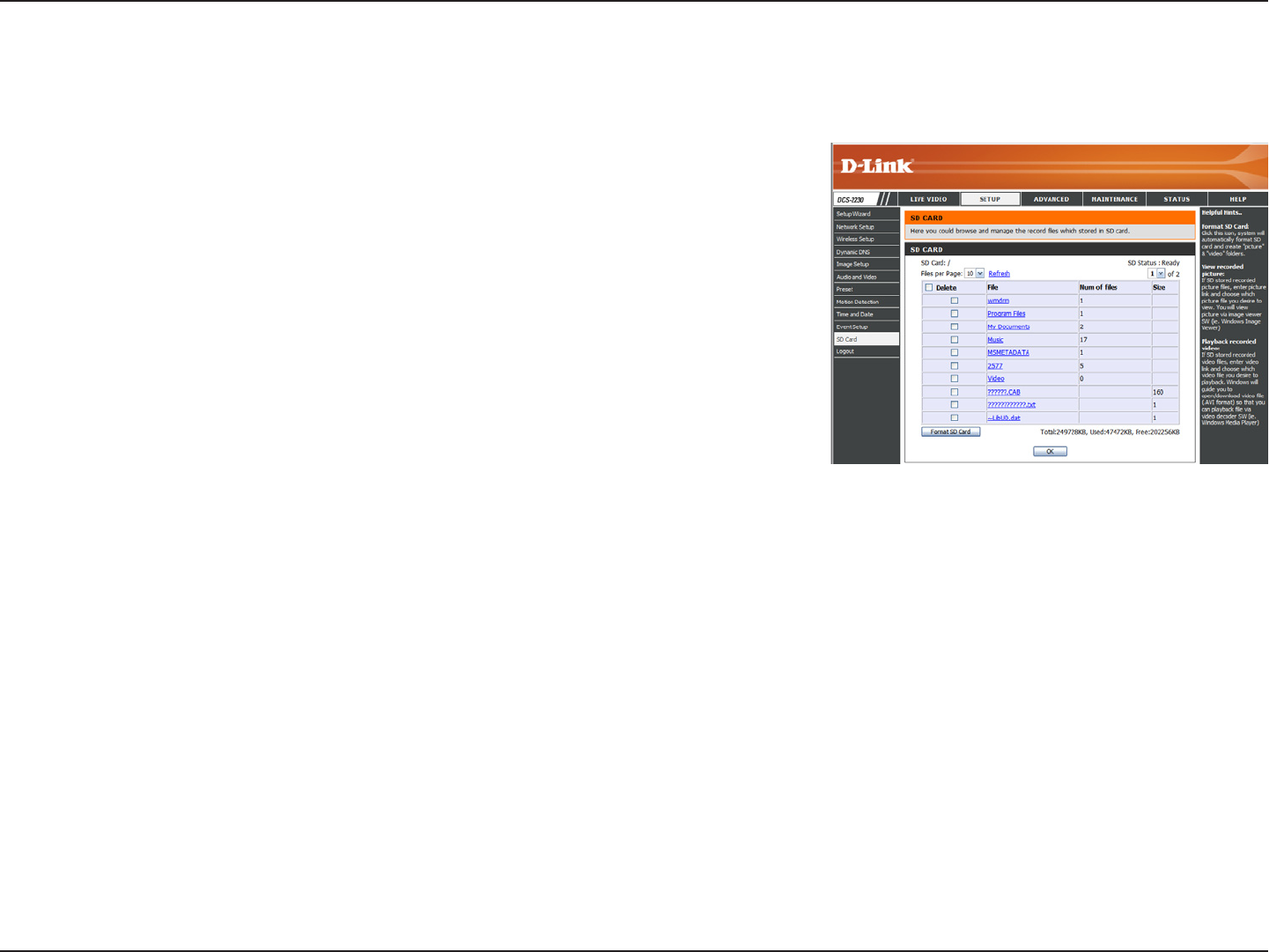
SD Card
Format SD Card:
View Recorded Picture:
Playback Recorded Video:
Refresh:
Click this icon to automatically format the SD card
and create "picture" & "video" folders.
If the picture les are stored on the SD card, click
on the picture folder and choose the picture le you
would like to view.
If video les are stored on the SD card, click on the
video folder and choose the video le you would like
to view.
Reloads the le and folder information from the SD
card.
Here you may browse and manage the recorded les which are stored on the SD card.
48D-Link DCS-2210/2230 User Manual
Conguration
Advanced
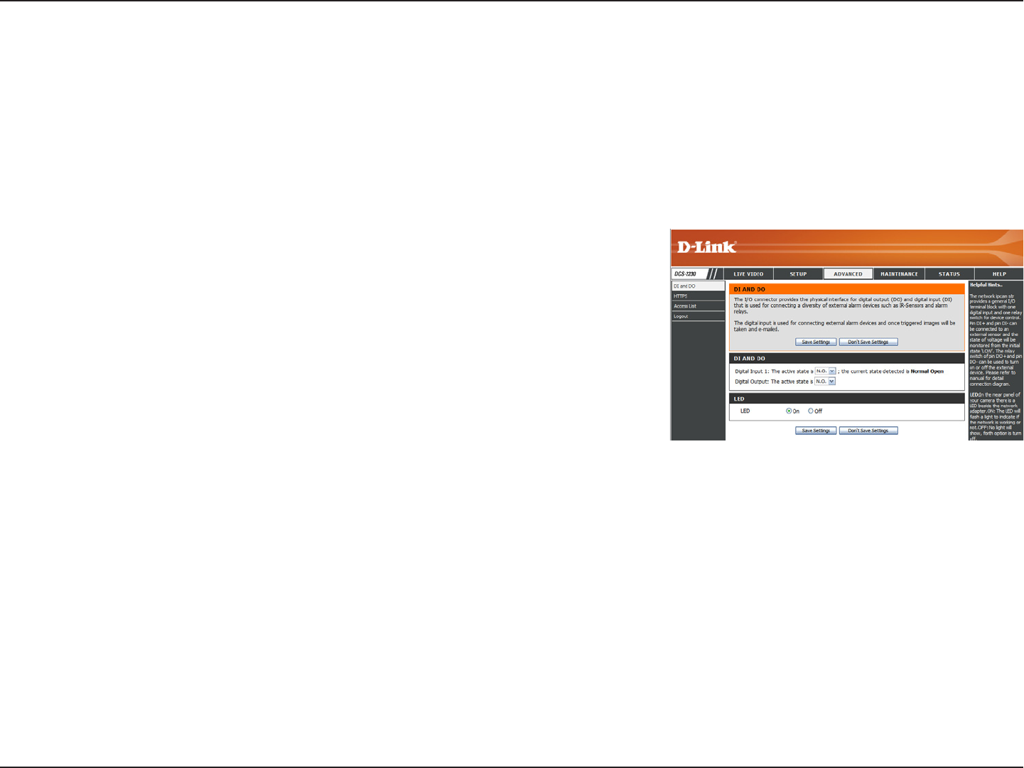
This screen allows you to control the behavior of digital input and digital output devices. The I/O connector provides the physical
interface for digital output (DO) and digital input (DI) that is used for connecting a variety of external alarm devices such as IR-Sensors
and alarm relays. The digital input is used for connecting external alarm devices and once triggered images will be taken and e-mailed.
After making any changes, click the Save Settings button to save your changes.
Digital Input/Output
Select D/I or D/O Mode:
LED:
The camera will send a signal when an event is
triggered, depending upon the type of device connected
to the DI circuit.
N.C. stands for Normally Closed. This means that
the normal state of the circuit is closed. Therefore
events are triggered when the device status changes
to "Open."
N.O. stands for Normally Open. This means that the
normal state of the circuit is open. Therefore events
are triggered when the device status changes to
"Closed."
You may specify whether or not to illuminate the LED
on the side of the camera.
49D-Link DCS-2210/2230 User Manual
Conguration
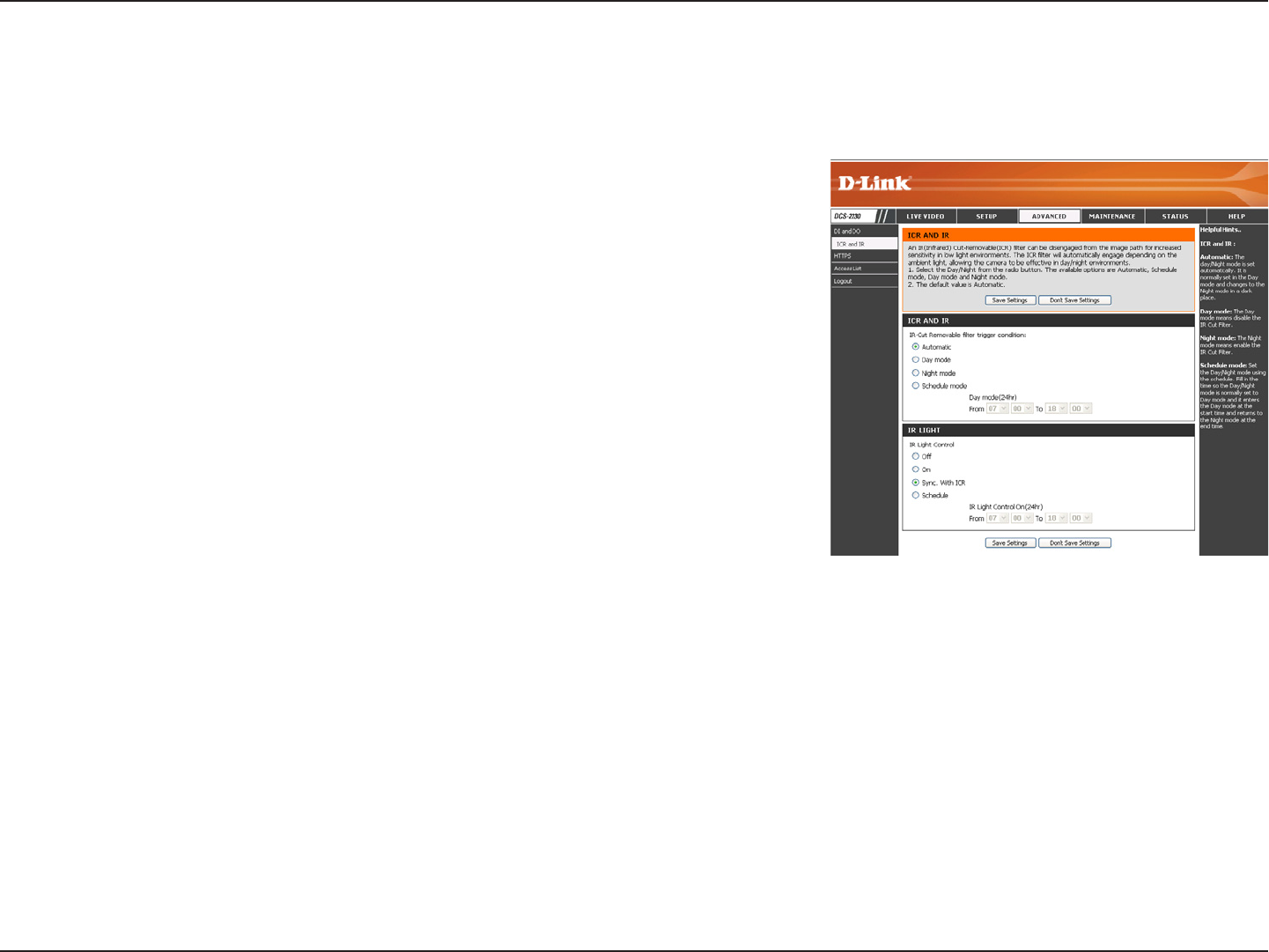
ICR and IR
Here you can congure the ICR and IR settings. An IR(Infrared) Cut-Removable(ICR) lter can be disengaged for increased sensitivity
in low light environments.
Automatic:
Day Mode:
Night Mode:
Schedule Mode:
IR Light Control:
Off:
On:
Sync:
Schedule:
The Day/Night mode is set automatically.
Generally, the camera uses Day mode and
switches to Night mode when needed.
Day mode enables the IR Cut Filter.
Night mode disables the IR Cut Filter.
Set up the Day/Night mode using a schedule.
The camera will enter Day mode at the starting
time and return to Night mode at the ending
time.
The camera can enable or disable the IR
(infrared) light according to your preferences.
This setting provides additional controls
depending on your specic application.
The IR light will always be off.
The IR light will always be on.
The IR light will turn on when the ICR sensor is on.
The IR light will turn on or off according to the schedule that you specify below.
50D-Link DCS-2210/2230 User Manual
Conguration
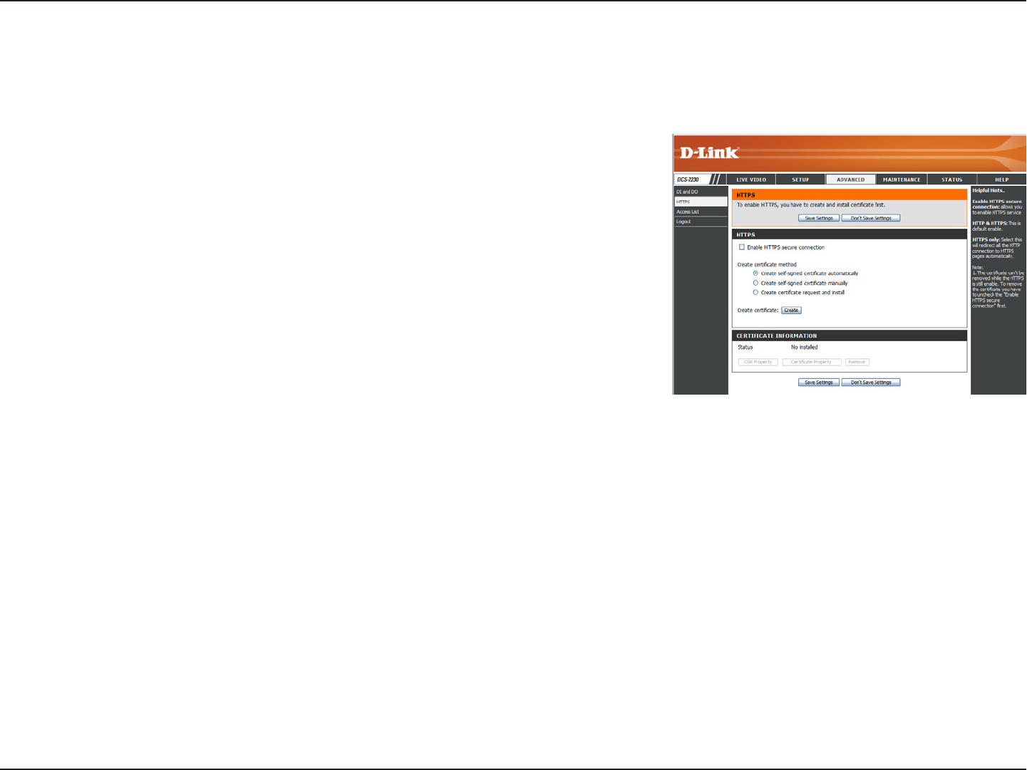
HTTPS
This page allows you to install and activate an HTTPS certicate for secure access to your camera. After making any changes, click the
Save Settings button to save your changes.
Enable HTTPS Secure
Connection:
Create Certicate Method:
Status:
Note:
Enable the HTTPS service.
Choose the way the certicate should be created.
Three options are available:
Create a self-signed certicate automatically
Create a self-signed certicate manually
Create a certicate request and install
Displays the status of the certicate.
The certicate cannot be removed while the HTTPS
is still enabled. To remove the certicate, you must
rst uncheck Enable HTTPS secure connection.
51D-Link DCS-2210/2230 User Manual
Conguration
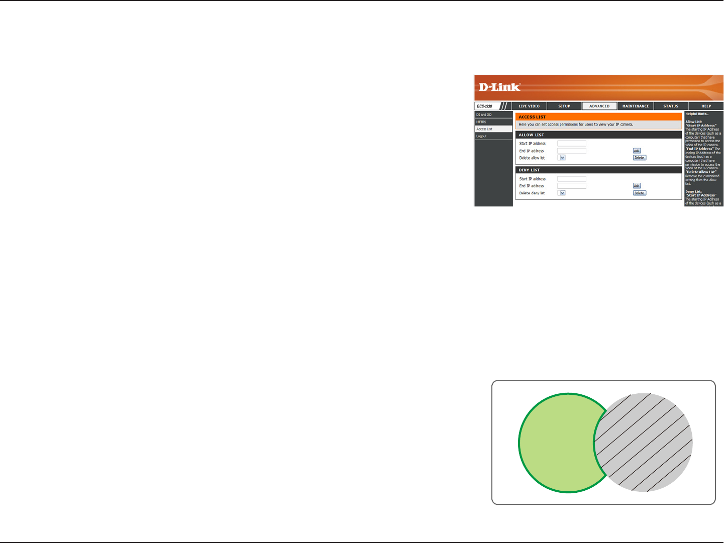
Access List
Here you can set access permissions for users to view your DDCS-2210/2230.
Allow list:
Start IP address:
End IP address:
Delete allow list:
Deny list:
Delete deny list:
The list of IP addresses that have the access right
to the camera.
The starting IP Address of the devices (such as a
computer) that have permission to access the video
of the camera. Click Add to save the changes made.
Note: A total of seven lists can be congured for
both columns.
The ending IP Address of the devices (such as a
computer) that have permission to access the video
of the camera.
Remove the customized setting from the Allow List.
The list of IP addresses that have no access rights
to the camera.
Remove the customized setting from the Delete List.
For example:
When the range of the Allowed List is set from
1.1.1.0 to 192.255.255.255 and the range of the
Denied List is set from 1.1.1.0 to 170.255.255.255.
Only users with IPs located between 171.0.0.0 and
192.255.255.255 can access the Network Camera.
Alowed
List
Denied
List
52D-Link DCS-2210/2230 User Manual
Conguration
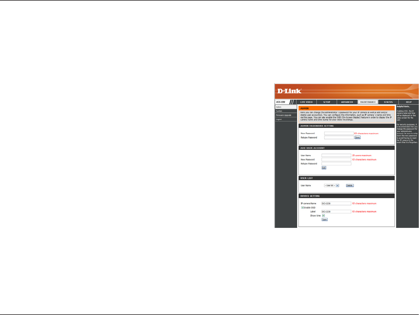
Maintenance
You may modify the name and administrator’s password of your camera, as well as add and manage the user accounts for accessing
the camera. You may also use this section to create a unique name and congure the OSD settings for your camera.
Admin Password Setting:
Add User Account:
User Name:
Password:
User List:
Camera Name:
Enable OSD:
Label:
Show Time:
Set a new password for the administrator’s account.
Add new user account.
The user name for the new account.
The password for the new account.
All the existing user accounts will be displayed here.
You may delete accounts includes in the list, but
please reserve at least one as guest.
Create a unique name for your camera that will
be added to the le name prex when creating a
snapshot or a video clip.
Select this option to enable the On-Screen Display
feature for your camera.
Enter a label for the camera.
Select this option to enable the time-stamp display
on the video screen.
Device Management
53D-Link DCS-2210/2230 User Manual
Conguration
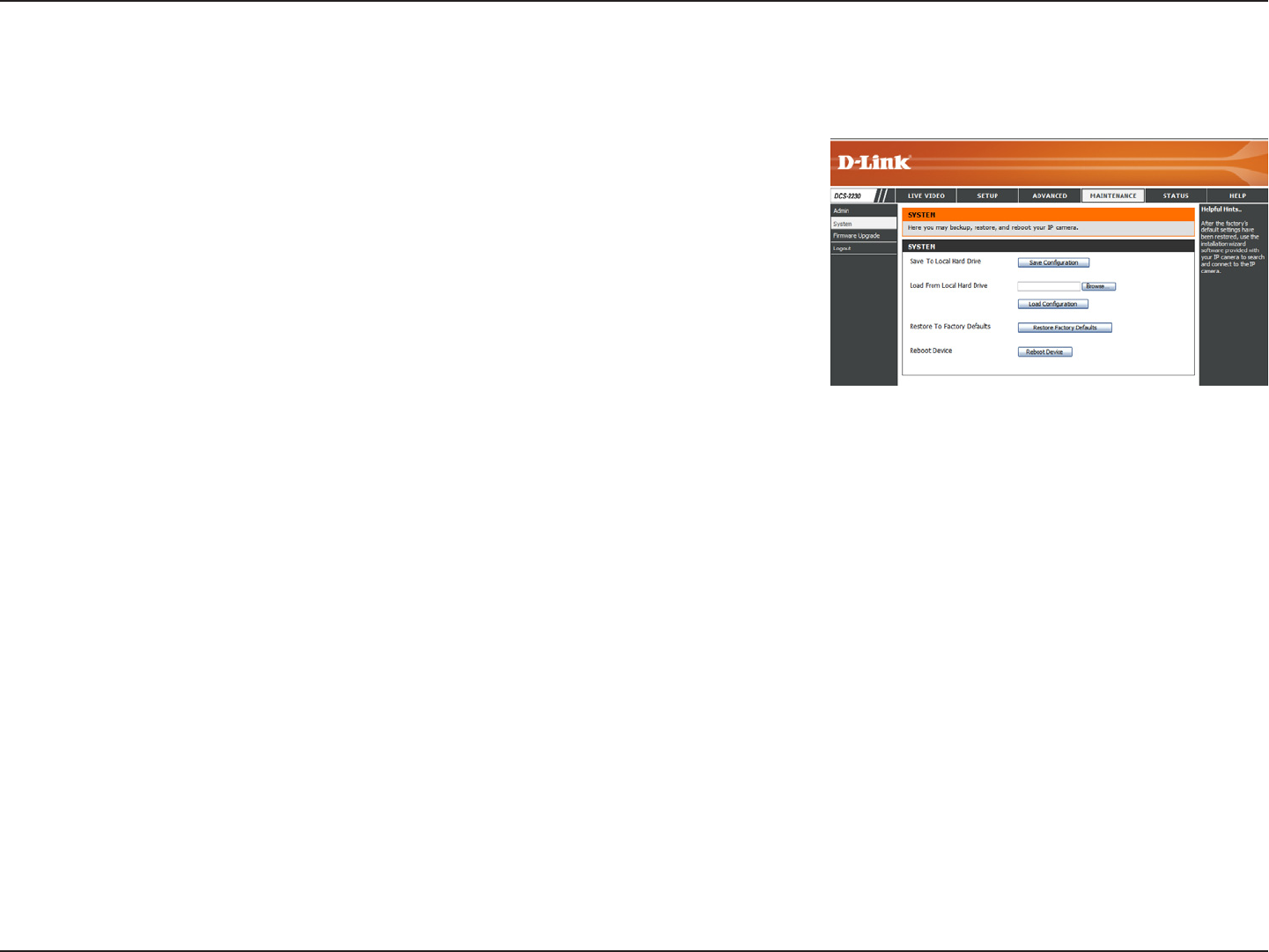
Backup and Restore
In this section, you may backup, restore and reset the camera conguration, or reboot the camera.
Save To Local Hard Drive:
Local From Local Hard Drive:
Restore to Factory Default:
Reboot Device:
You may save and document your current settings
into your computer.
Locate a pre-saved conguration by clicking
Browse and then restore the pre-dened settings to
your camera by clicking Load Conguration.
You may reset your camera and restore the factory
settings by clicking Restore Factory Defaults.
This will restart your camera.
54D-Link DCS-2210/2230 User Manual
Conguration
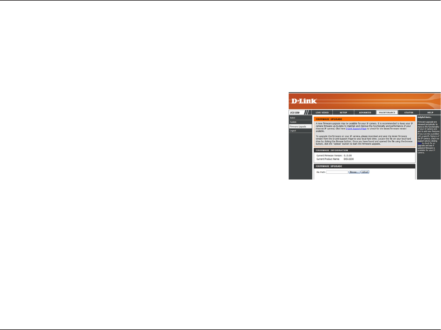
Firmware Upgrade
The camera's current rmware version will be displayed on this screen. You may visit the D-Link Support Website to check for the latest
available rmware version.
To upgrade the rmware on your DCS-2210/2230, please download and save the latest rmware version from the D-Link Support
Page to your local hard drive. Locate the le on your local hard drive by clicking the Browse button. Select the le and click the Upload
button to start upgrading the rmware.
Current Firmware Version:
Current Product Name:
File Path:
Upload:
Displays the detected rmware version.
Displays the camera model name.
Locate the le (upgraded rmware) on your hard
drive by clicking Browse.
Uploads the new rmware to your camera.
55D-Link DCS-2210/2230 User Manual
Conguration
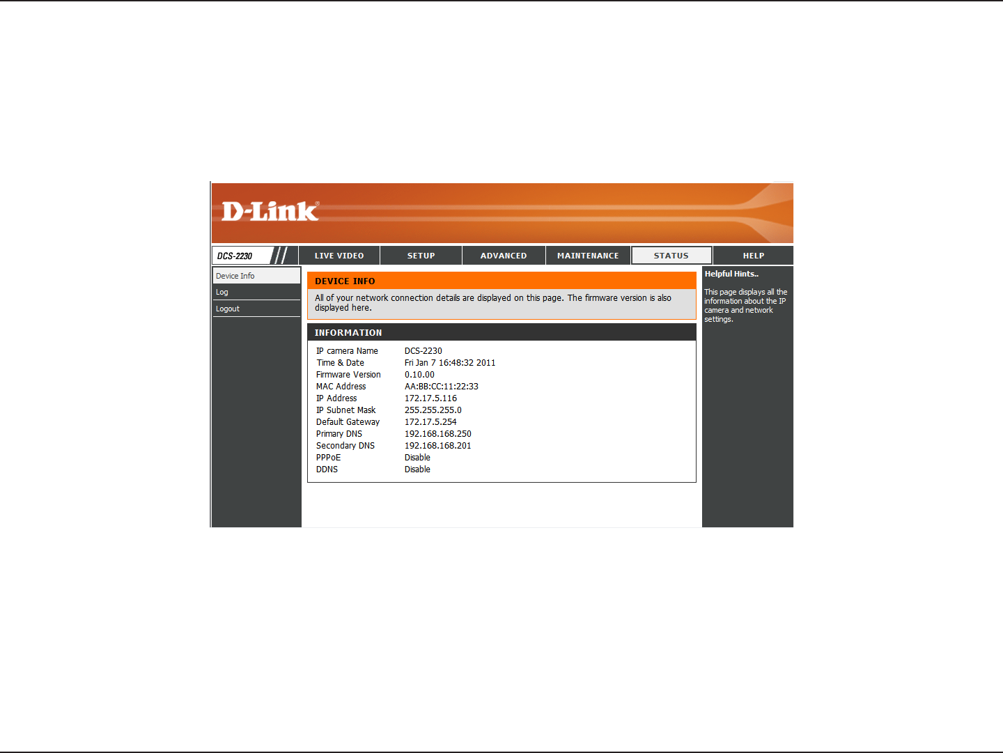
Status
This page displays detailed information about your device and network connection.
Device Info
56D-Link DCS-2210/2230 User Manual
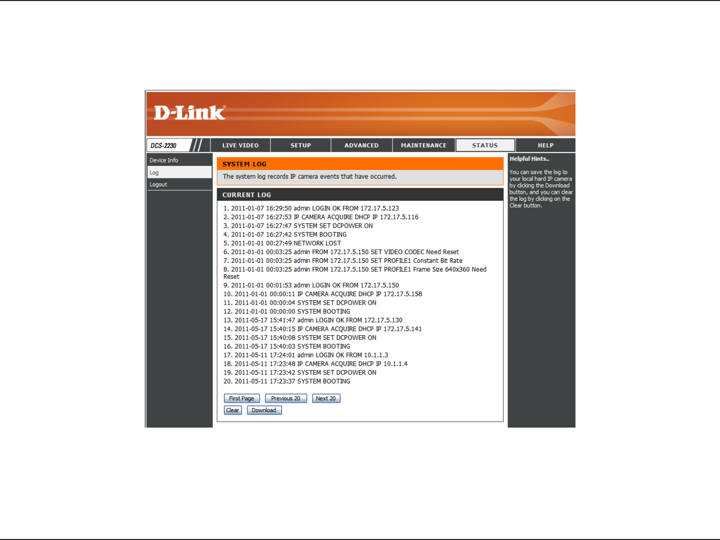
Conguration
This page displays the log information of your camera. You may download the information by clicking Download. You may also click
Clear to delete the saved log information.
Logs
57D-Link DCS-2210/2230 User Manual
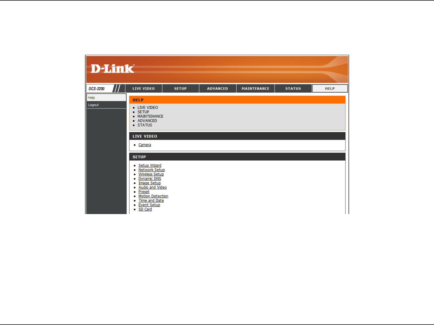
Conguration
This page provides helpful information regarding camera operation.
Help
58D-Link DCS-2210/2230 User Manual
Appendix
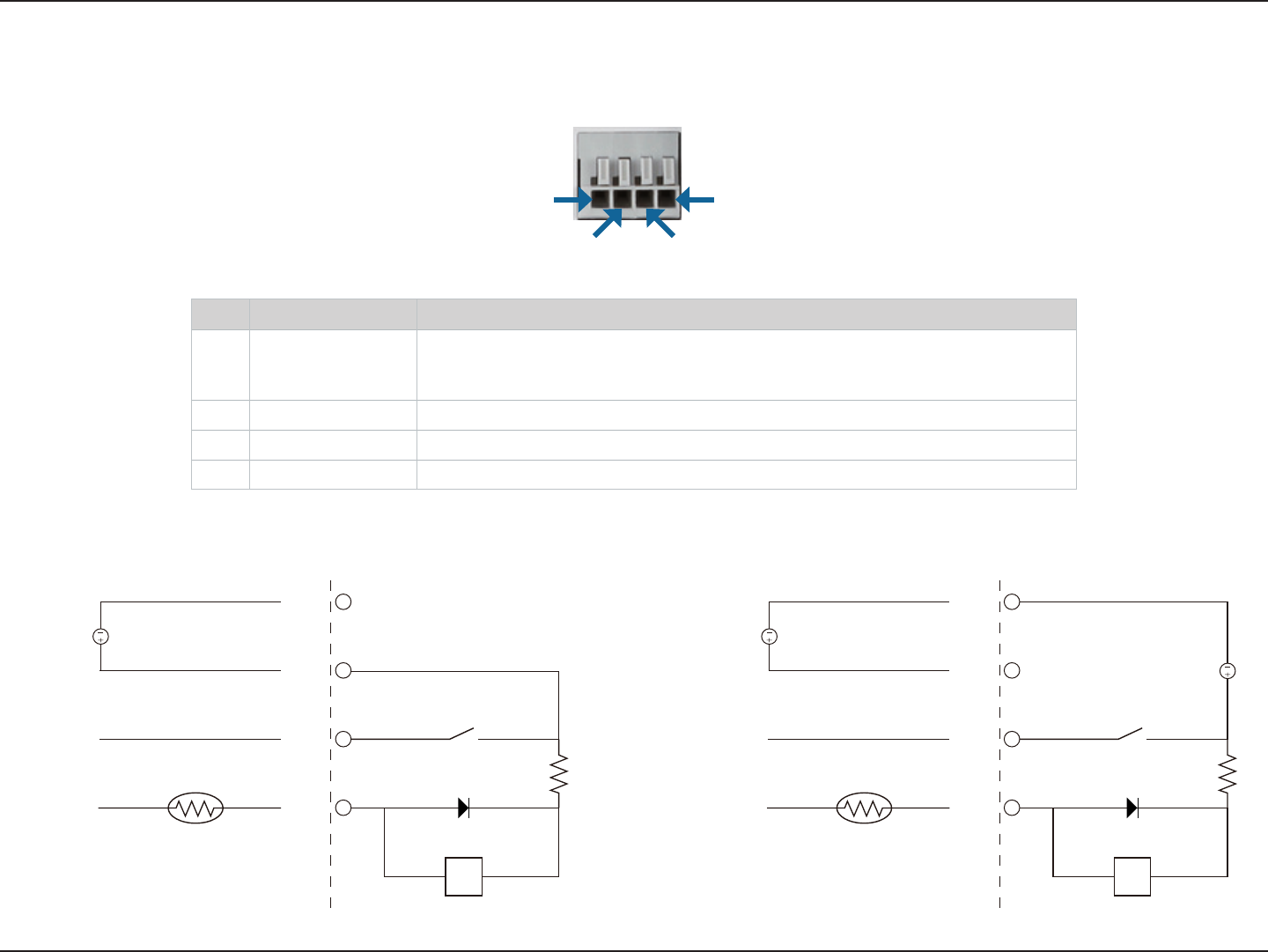
DI/DO Input Specications
Appendix
Pin 1 Pin 4
Pin 3Pin 2
PIN FUNCTION NOTE
1 Digital Out (DO) Uses an open-drain NFET transistor with the source connected to GND in camera.
If used with an external relay, a diode must be connected in parallel with the load
for protection against voltage transients. Max loading is 100 mA.
2 Digital In (DI) A switch from DI to DC 5 V, activated by setting NO. or NC.
3 DC5V OUTPUT DC 5 V Output / Max. 100 mA
4 GND GND
Internal 5V Power External 3~12V Power
DO
DI
5V
DND
N.C / N.O
100 mA
ALARM
Reed switch
Diode
DC Power 5V
R
DO
DI
5V
DND
N.C / N.O
ALARM
Reed switch
Diode
DC Power 5V
R
DC Power 3V~12V
100 mA

59D-Link DCS-2210/2230 User Manual
Appendix
Technical Specications
Camera Camera Hardware
Profile
1/2.7” 2 Megapixel progressive CMOS sensor
IR illumination distance: 5 m
Minimum illumination 0 lux with IR illumination
Built-in Infrared-Cut Removable (ICR)
lter module
Built-in PIR sensor
Built-in microphone and speaker
10x digital zoom
Fixed length 4.37 mm
Aperture F2.0
Angle of view:
(H) 67.4°
(V) 40.8°
(D) 75°
Image Features
Configurable image size, quality, frame rate, and bit rate
Time stamp and text overlays
Configurable motion detection windows
3 configurable privacy mask zones
Configurable shutter speed, brightness, saturation, contrast, and
sharpness
Video Compression
Simultaneous H.264/MPEG-4/MJPEG format compression
JPEG for still image
H.264/MPEG-4 multicast streaming
Video Resolution 16:9 - 1920 x 1080 (up to 15 fps), 1280 x 720, 800 x 450, 640 x 360, 480 x 270, 320 x 176, 176 x 144 up to 30 fps
4:3 - 1440 x 1080 (up to 15 fps), 1280 x 960, 1024 x 768, 800 x 600, 640 x 480, 320 x 240, 176 x 144 up to 30 fps
Audio Support G.726
External Device
Interface
1 DI / 1 DO
Micro SD card slot
Network Network Protocols IPv4, TCP/IP, UDP, ICMP, DHCP Client, NTP Client (D-Link), DNS Client, DDNS Client (D-Link), SMTP Client, FTP Client, HTTP / HTTPS,
Samba Client, PPPoE, UPnP Port Forwarding, RTP / RTSP/ RTCP, IP filtering, 3GPP, IGMP, ONVIF Compliant
Security
Administrator and user group protection
Password authentication
HTTP and RTSP digest encryption

60D-Link DCS-2210/2230 User Manual
Appendix
System
Management
System
Requirements for
Web Interface
Operating System: Microsoft Windows 7/Vista/XP/2000
Browser: Internet Explorer, Firefox, Netscape, Opera
Event Management
Motion detection
Event notification and upload snapshots/video clips via HTTP,
SMTP, or FTP
Supports multiple HTTP, SMTP, and FTP servers
Multiple event notifications
Multiple recording methods for easy backup
Remote Management
Configuration accessible via web browser
Take snapshots/video clips and save to local hard drive or NAS via web browser
Mobile Support Windows 7/Vista/XP system, Pocket PC, or mobile phone with 3GPP playback support
D-ViewCam™
System
Requirements
Operating System: Microsoft Windows 7/Vista/XP
Web Browser: Internet Explorer 6 or higher
Protocol: Standard TCP/IP
D-ViewCam™
Software Functions
Remote management/control of up to 32 cameras
Viewing of up to 32 cameras on one screen
Supports all management functions provided in web interface
Scheduled motion triggered, or manual recording options
General Power Input 5 V DC 1.2 A, 50/60 Hz, PoE ( DCS-2210 only )
Max. Power
Consumption
DCS-2210: 3.5 watts
DCS-2230: 4 watts
Operating
Temperature 0 to 40 ˚C (32 to 104 ˚F)
Storage Temperature -20 to 70 °C (-4 to 158 °F)
Humidity 20% to 80% non-condensing
Weight DCS-2210: 80 g
DCS-2230: 75 g
Certifications CE, CE LVD, FCC(Class B), C-Tick
Technical Specications
* This device complies with part 15 of the FCC Rules.
Operation is subject to the following two conditions:
(1) This device may not cause harmful interference.
(2) This device must accept any interference received, including interference that may cause undesired operation.
61D-Link DCS-2210/2230 User Manual
Appendix
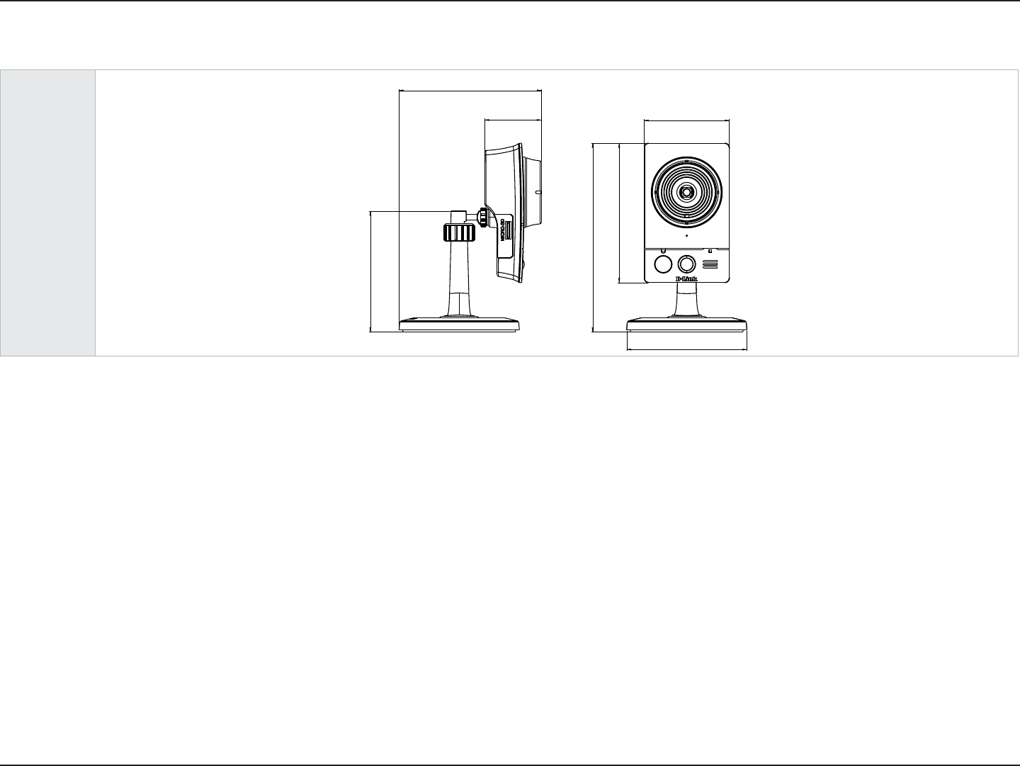
Dimensions
58
95
128.6
82.3
82
38.7
97
DCS-2210/2230
FCC Notices
This device complies with Part 15 of the FCC Rules. Operation is subject to the following
two conditions: (1) this device may not cause harmful interference, and (2) this device
must accept any interference received, including interference that may cause undesired
operation.
CAUTION: Change or modification not expressly approved by the party responsible
for compliance could void the user’s authority to operate this equipment.
This equipment has been tested and found to comply with the limits for a Class B
digital device, pursuant to Part 15 of the FCC Rules. These limits are designed to provide
reasonable protection against harmful interference in a residential installation. This
equipment generates, uses and can radiate radio frequency energy and, if not installed
and used in accordance with the instructions, may cause harmful interference to radio
communications. However, there is no guarantee that interference will not occur in a
particular installation. If this equipment does cause harmful interference to radio or
television reception, which can be determined by turning the equipment off and on, the
user is encouraged to try to correct the interference by one or more of the following
measures:
--Reorient or relocate the receiving antenna.
--Increase the separation between the equipment and receiver.
--Connect the equipment into an outlet on a circuit different from that to which the receiver
is connected.
--Consult the dealer or an experienced radio/TV technician for help.
CAUTION:
Any changes or modifications not expressly approved by the grantee of this device could
void the user's authority to operate the equipment.
RF exposure warning
This equipment must be installed and operated in accordance with provided instructions
and the antenna(s) used for this transmitter must be installed to provide a separation
distance of at least 20 cm from all persons and must not be co-located or operating in
conjunction with any other antenna or transmitter. End-users and installers must be
provide with antenna installation instructions and transmitter operating conditions for
satisfying RF exposure compliance."
Canada Notices
Industry Canada regulatory information
Operation is subject to the following two conditions: (1) this device may not cause
interference, and (2) this device must accept any interference, including interference
that may cause undesired operation of the device.
The user is cautioned that this device should be used only as specified within this
manual to meet RF exposure requirements. Use of this device in a manner
inconsistent with this manual could lead to excessive RF exposure conditions.
Le présent appareil est conforme aux CNR d'Industrie Canada
applicables aux appareils radio exempts de licence. L'exploitation est
autorisée aux deux conditions suivantes : (1) l'appareil ne doit pas
produire de brouillage, et (2) l'utilisateur de l'appareil doit accepter tout
brouillage radioélectrique subi, même si le brouillage est susceptible
d'en compromettre le fonctionnement.
RF exposure warning
This equipment must be installed and operated in accordance with
provided instructions and the antenna(s) used for this transmitter must
be installed to provide a separation distance of at least 20 cm from all
persons and must not be co-located or operating in conjunction with any
other antenna or transmitter. End-users and installers must be provide
with antenna installation instructions and transmitter operating
conditions for satisfying RF exposure compliance."
Cet équipement doit être installé et utilisé conformément aux
instructions fournies et de l'antenne (s) utilisé pour cet émetteur doit être
installé pour fournir une distance de séparation d'au moins 20 cm de
toute personne et ne doit pas être co-localisés ou fonctionnant en
conjonction avec une autre antenne ou transmetteur. Les utilisateurs
finaux et installateurs doivent être fournir des instructions d'installation
de l'antenne et des conditions de fonctionnement du transmetteur de la
conformité sur l'exposition aux RF