D Link CS932LA1 Wireless N Day/Night Home Network Camera User Manual DCS 930 A2 UserMan 2
D Link Corporation Wireless N Day/Night Home Network Camera DCS 930 A2 UserMan 2
D Link >
Contents
(DCS-930_A2)UserMan-2
16D-Link DCS-930 User Manual
Section 3 - Configuration
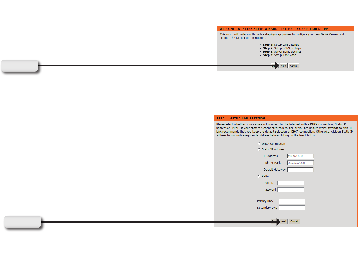
Internet Connection Setup Wizard
This wizard will guide you through a step-by-step process to congure your
new D-Link Camera and connect the camera to the Internet.
You may congure your camera using
• DHCP Connection (by default), where your DHCP server will
automatically assign dynamic IP to your device.
• Static IP Address if your ISP has already assigned an IP address to
you.
• PPPoE connection, where your camera is directly connected to the
Internet through a DSL modem.
* Input the DNS information if you have chosen and assigned a Static IP
Address for your camera.
Click Next
Click Next
17D-Link DCS-930 User Manual
Section 3 - Configuration
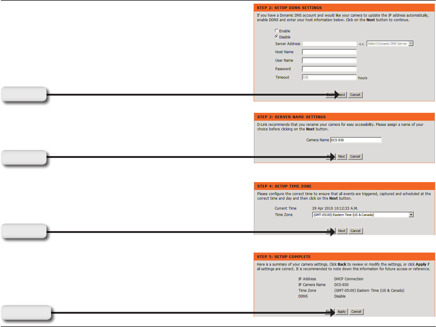
Enter a name for your camera.
Congure the correct time to ensure that all events triggered, captured and
scheduled at the right time.
This page displays your congured settings. Click Apply to save and
activate the setting, or Back to change your settings.
If you have a Dynamic DNS account and would like the camera to
update your IP address automatically, enable DDNS and enter your host
information.
Click Next
Click Next
Click Next
Click Apply
18D-Link DCS-930 User Manual
Section 3 - Configuration
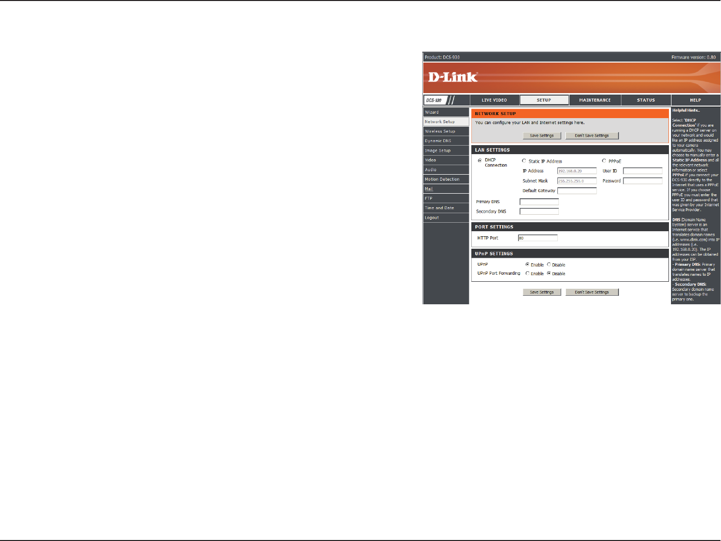
Network Setup
Select this connection if you have a DHCP server running on your
network and would like a dynamic IP address to be updated to your
camera automatically.
You may obtain a static or xed IP address and other network
information from your network administrator for your camera. A
static IP address will ease you for accessing your camera in the
future.
IP Address: The xed IP address
Subnet Mask: The default value is “255.255.255.0.” Used to
determine if the destination is the same subnet.
Default Gateway: The gateway used to forward frames to
destinations in a different subnet. Invalid gateway settings may
cause the failure of transmissions to a different subnet.
Primary DNS: Primary domain name server that translates names to IP addresses.
Secondary DNS: Secondary domain name server to backup the Primary DNS.
DHCP:
Static IP Client:
PPPoE Settings:
Port Settings:
UPnP Settings:
This section allows you to congure your network settings.
If you are using a PPPoE connection, enable it and enter the User Name and Password for your PPPoE account. You can get
this information from your Internet service provider (ISP).
You may congure a Second HTTP port that will allow you to connect to the camera via a standard web browser. The port can be
set to a number other than the default TCP ports 80. A corresponding port must be opened on the router. For example, if the port
is changed to 1010, users must type “http://192.168.0.100:1010” instead of only “http://192.168.0.100”.
Enable this setting to congure your camera as an UPnP device in the network.
19D-Link DCS-930 User Manual
Section 3 - Configuration
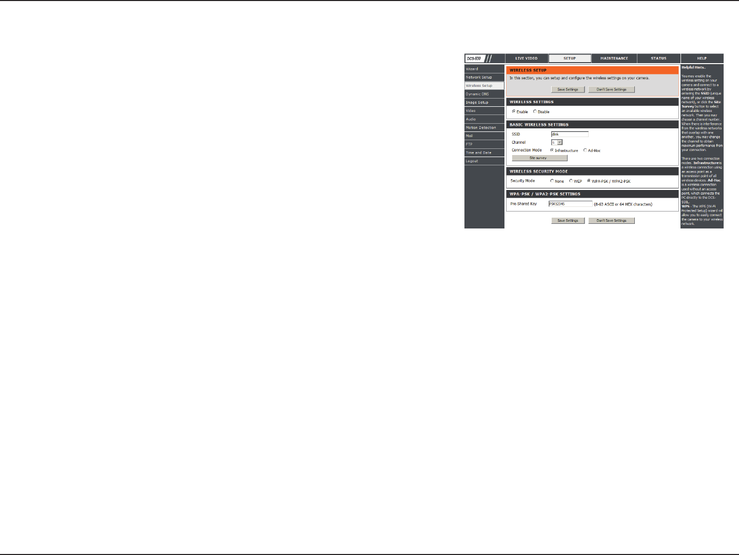
Setup > Wireless
Service Set Identier, an identier for your wireless network.
The default setting is channel 6. Select the same channel that is using by other wireless devices within your network. When
there is interference from the wireless networks that overlap with one another, you may change the channel to obtain maximum
performance for your connection.
Infrastructure is a wireless connection using an access point as a transmission point of all wireless devices. Ad-Hoc is a
wireless connection used without an access point, where your DCS-930 is directly connecting to your PC. This is done using
the on-board wireless adapter on the DCS-930 connected to a wireless adapter on the PC.
This page will allow you to select a wireless network that the DCS-930 was able to detect.
For security, there are three choices; None, WEP, and WPA-PSK / WPA2-PSK. Select the same encryption method that is being
used by your wireless device/ router.
An appropriate Preshared Key, which is needed in order to connect to the wireless network..
SSID:
Channel:
Connection Mode:
Site Survey:
Wireless Security
Mode:
WPA-PSK /
WPA2PSK
Settings:
Wireless Interface
This section allows you to setup and congure the wireless settings
on your camera.
DCS-930L_A2
DCS-930L_A2
DCS-930L_A2
DCS-930_A2
DCS-930_A2
DCS-930_A2
20D-Link DCS-930 User Manual
Section 3 - Configuration
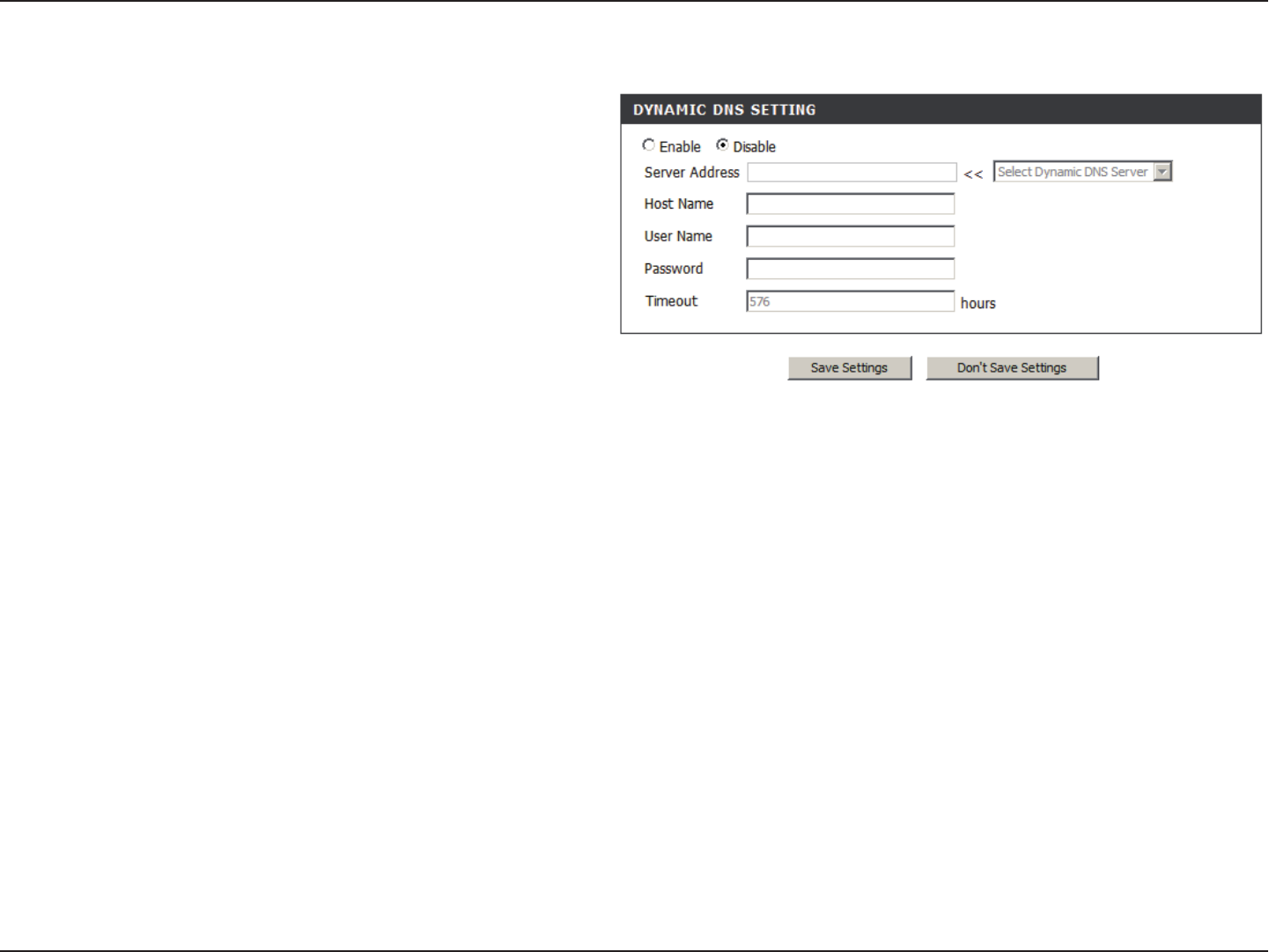
(Dynamic Domain Name Server) will hold a DNS host name and synchronize the public IP address of the modem when it
has been modied. The username and password are required when using the DDNS service.
Click to enable the DDNS function.
Select your Dynamic DNS Server from the pull down menu.
Enter the host name of the DDNS server.
Enter your username or e-mail used to connect to the DDNS.
Enter your password used to connect to the DDNS server.
DDNS:
Enable:
Server Address:
Host Name:
User Name:
Password:
Setup > DDNS
This section allows you to congure the DDNS setting for your
camera. DDNS will allow all users to access your camera using
a domain name instead of an IP address.
21D-Link DCS-930 User Manual
Section 3 - Configuration
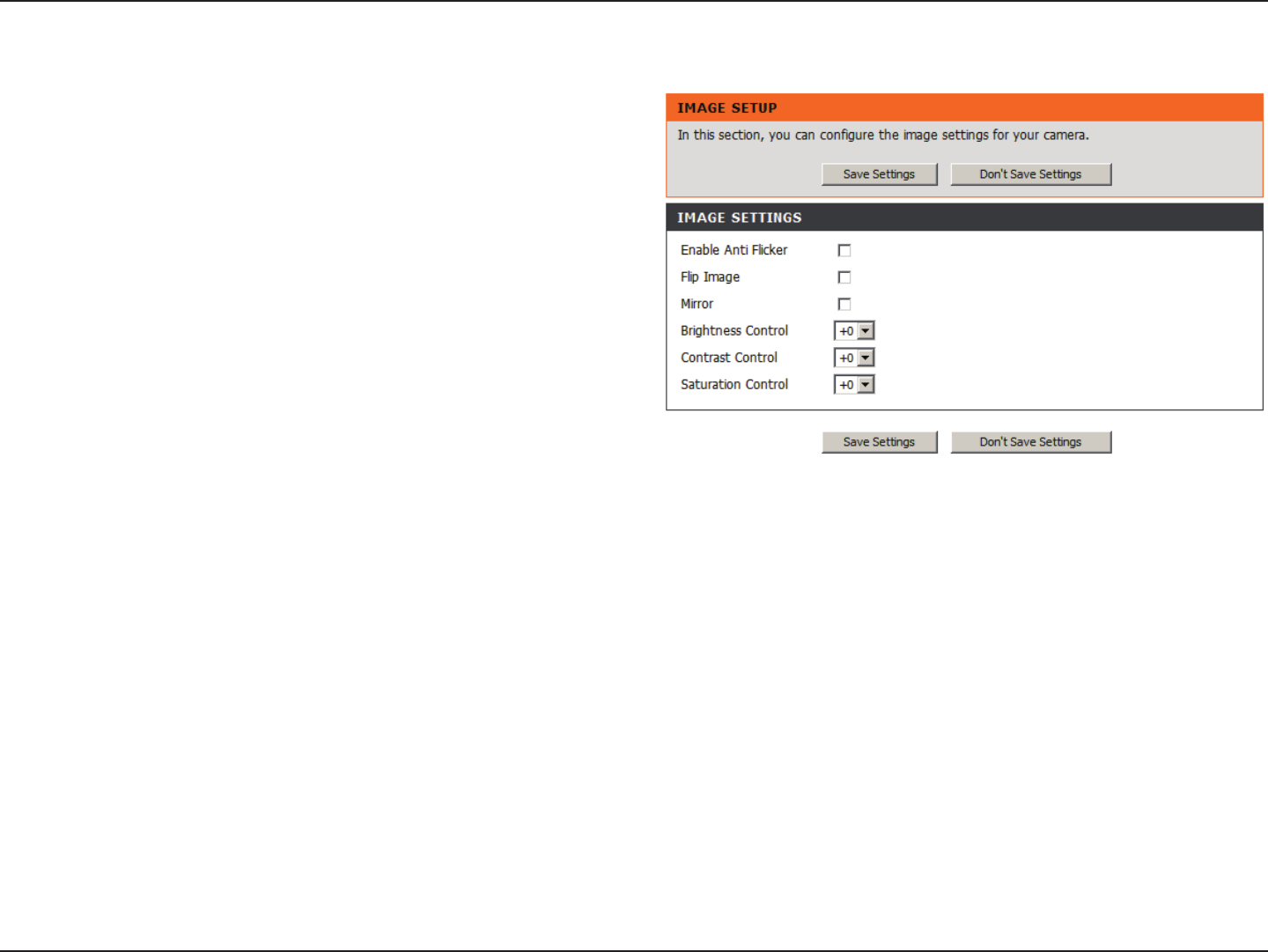
Setup > Image Setup
Select this box to enable antiicker.
Select this box to vertically rotate the video. If the camera is installed upside down, Flip Image and Mirror should both be
checked.
Horizontally rotates the video.
Allows you to adjust the brightness level.
Allows you to adjust the contrast level.
Allows you to adjust the saturation level.
Enable
Antiicker:
Flip Image:
Mirror:
Brightness
Control:
Contrast
Control:
Saturation
Control:
Image Settings
This section allows you to congure the image settings for your
camera.
22D-Link DCS-930 User Manual
Section 3 - Configuration
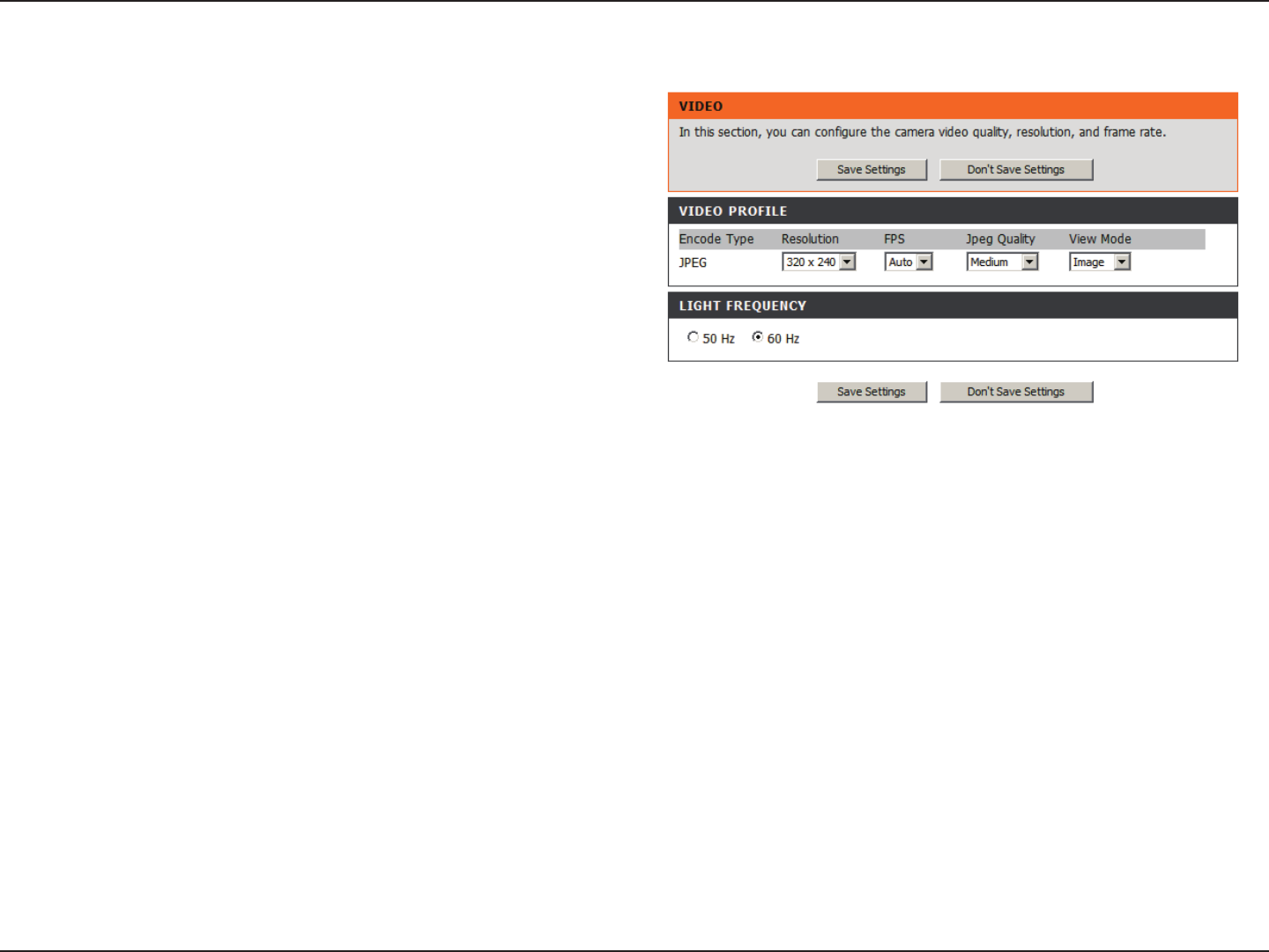
Setup > Video
Video Prole:
Light
Frequency:
Video Conguration
Encode Type:
Resolution:
FPS:
JPEG Quality:
View Mode:
The compression format used when viewing your camera.
Select the desired video resolution from three formats: 640x480, 320x240, and 160x120. The higher setting can
obtain better quality. However, it will use more resource within your network.
Select the optimal setting depending on your network status. Please note that the higher setting can obtain better
quality. However, it will use more resources within your network.
Choose one of ve levels of image quality: Highest, High, Medium, Low, and Lowest.
Select the mode for viewing the camera image. Select Image for a still images, ActiveX for Internet Explorer, or
Java for other web browsers.
Select the proper frequency (50Hz or 60Hz) to reduce image icker.
This section allows you to congure the video settings for
your camera.
This section allows you to change the Encode Type, Resolution, FPS, and Quality.
23D-Link DCS-930 User Manual
Section 3 - Configuration
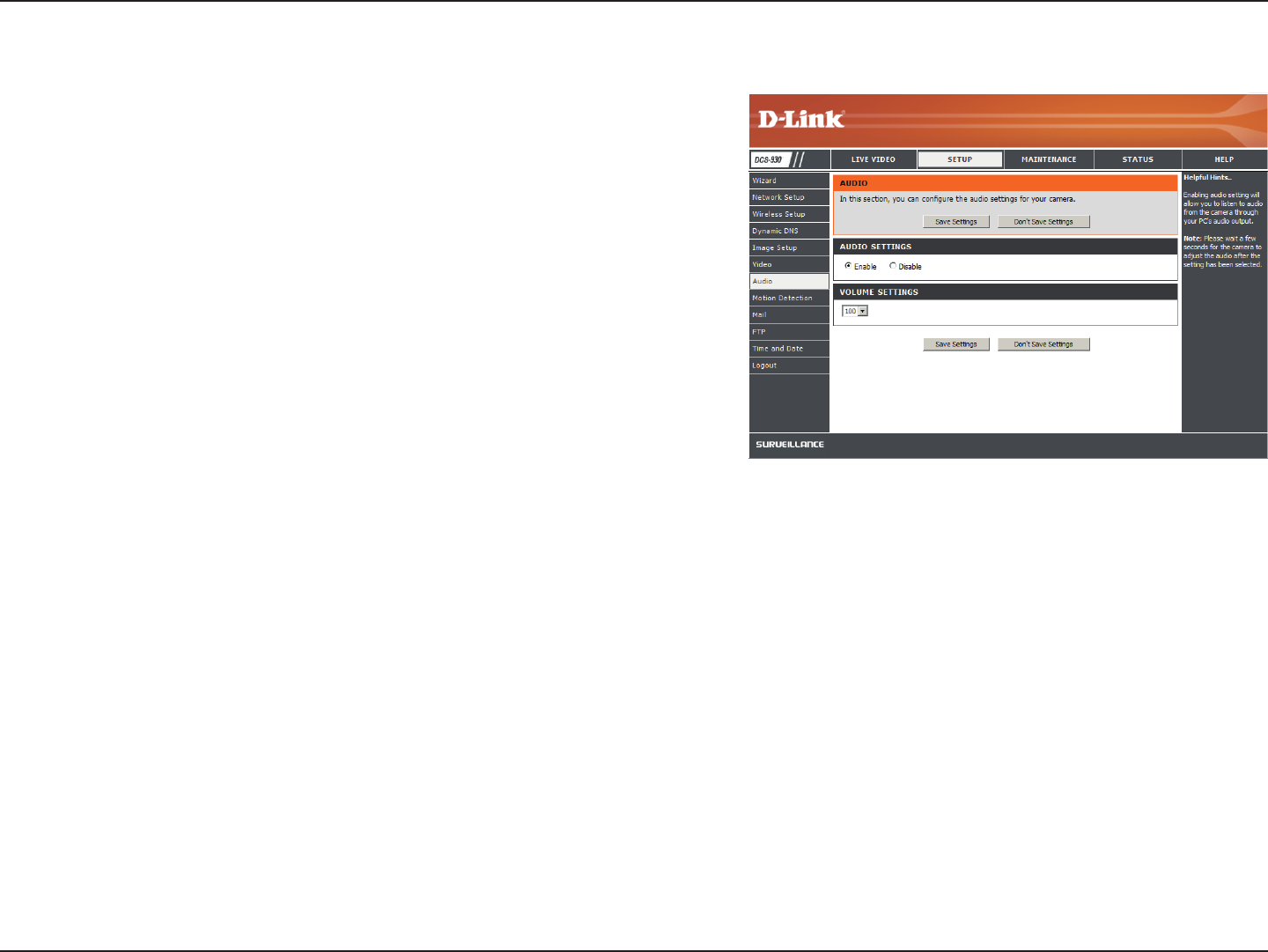
Setup > Audio
Enabling audio setting will allow you to listen to audio from the camera
through your PC’s audio output.
Note: Please wait a few seconds for the camera to adjust the audio
after the setting has been selected.
Audio Settings:
Volume
Settings:
You may Enable or Disable the camera audio feed.
Select the desired volume percentage level.
24D-Link DCS-930 User Manual
Section 3 - Configuration
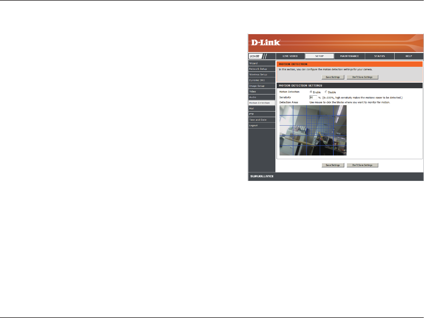
Setup > Motion Detect
Enabling Video Motion will allow your camera to use the motion detection
feature. You may draw a nite motion area that will be used for monitoring.
Motion
Detection:
Sensitivity:
Detection
Areas:
Select this box to enable the motion detection feature of your
camera.
Species the measurable difference between two sequential
images that would indicate motion. Please enter a value
between 0 and 100.
Use your mouse to click on the blocks that you would like to
monitor for motion.
25D-Link DCS-930 User Manual
Section 3 - Configuration
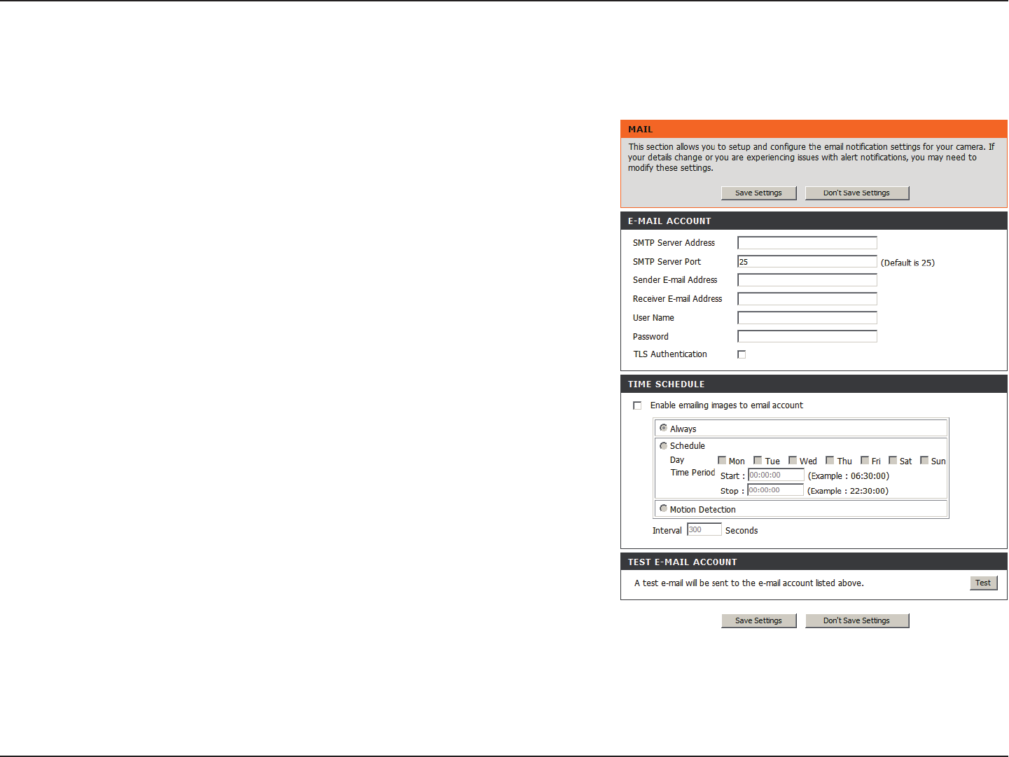
Setup > Mail
Email Account
SMTP Server
Address:
Sender e-mail
Address:
Receiver e-mail
Address:
User Name:
Password:
This is the domain name or IP address of your external e-mail
server.
This is the e-mail address of the person sending the camera
snapshots.
This is the e-mail address of the recipient.
If the SMTP server uses authentication, you must enter your user
name here.
This is the password that corresponds to your user name to
connect to the SMTP server.
This section allows you to congure the email notication settings for your
camera.

26D-Link DCS-930 User Manual
Section 3 - Configuration
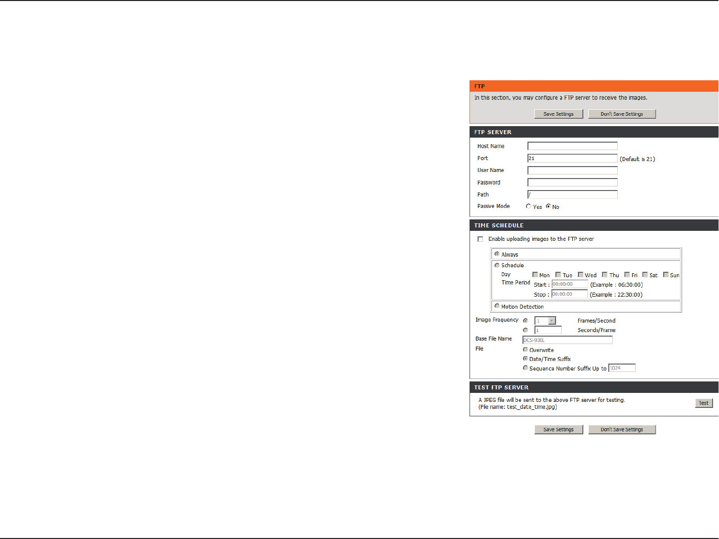
Time Schedule
Enable e-mail
image to e-mail
account:
Interval:
Test E-mail
Account:
Choosing Always will start sending snapshots to the recipient’s e-mail account right away. Choosing Schedule will allow you to
schedule when to start and stop the sending of snapshots to the recipient’s e-mail account.
The frequency of the snapshot interval can also be congured from 1 to 65535 seconds.
This will send a snapshot to the e-mail account that you have congured in the E-mail section. If you have congured the SMTP
account correctly, you will be able to send a test le to the e-mail account of the recipient.
27D-Link DCS-930 User Manual
Section 3 - Configuration
Setup > FTP
FTP Server
Host Address:
Port Number:
User Name:
Password:
Directory Path:
Passive Mode:
This is the IP address of the FTP server that you will be connecting to.
Default is port 21. If changed, external FTP client program must change
the server connection port accordingly.
Species the user name to access the external FTP server. If you are
to upload snapshots to an FTP server you will need to ll in the Domain
name or IP address of your external FTP server. The following user
settings must be correctly congured for remote access.
Species the password to access the external FTP server.
Species the destination folder in the external FTP server.
Enabling passive mode will allow access to an external FTP server if
your camera is behind a router protected by a rewall.
This section allows you to congure a FTP server to receive images from the camera.

28D-Link DCS-930 User Manual
Section 3 - Configuration
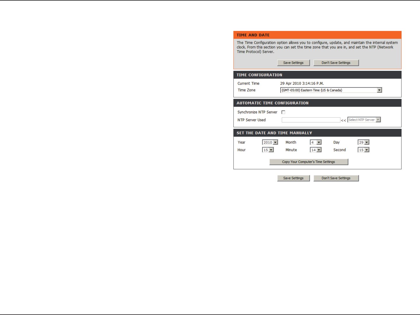
Time Schedule
Enable upload image to
FTP server:
Always:
Schedule:
Video Frequency:
Base File Name:
File:
Test FTP Server:
Checking this box will enable video uploads to the FTP server you have selected.
Selecting this option allows snapshots to be uploaded to your FTP as soon as you click Apply.
Selecting this option allows you to congure specic times when you want the snapshots to be uploaded to your FTP
server.
Users can select in frames per second (1, 2, 3 or auto, in auto this could go to 4). The user can also select a duration for
each frame from 1 to 65535 seconds.
This will be the name that precedes the time, for example DCS9302010072116425101.jpg. This means that the camera
took a snapshot in the year 2010, July 21 at 16th hour (4 o’clock), 42 minutes and 51 seconds and it is picture number
one.
If Overwrite is selected, only a few images will be constantly refreshed, depending on how many snapshots you choose
to have sent. Select Date/Time Sufx and the pictures will be named with a date and time also. An example of this can
be seen above under the Base le name category. Select a Sequence Number Sufx up to 1024 and all the pictures
will be numbered from 1-1024. Up to 1024 pictures can be congured. Picture number 1025 will reset to number 1.
This will send a snapshot to the FTP server that you have congured in the Upload section. If you have congured the
FTP correctly, you will be able to see a test le on your FTP server.
29D-Link DCS-930 User Manual
Section 3 - Configuration
Setup > Time and Date
Test FTP Server:
Synchronize NTP Server:
Copy your Computer’s
Time Settings:
Set the Date and Time
Manually:
Select the time zone for your region from the
pull-down menu.
Network Time Protocol will synchronize your
camera with an Internet time server. Choose
the one that is closest to your camera.
Click to synchronize the time information from
your PC.
Select this to set the time manually.
This section allows you to congure the settings of the internal system
clocks for your camera.
30D-Link DCS-930 User Manual
Section 3 - Configuration
Maintenance > Admin
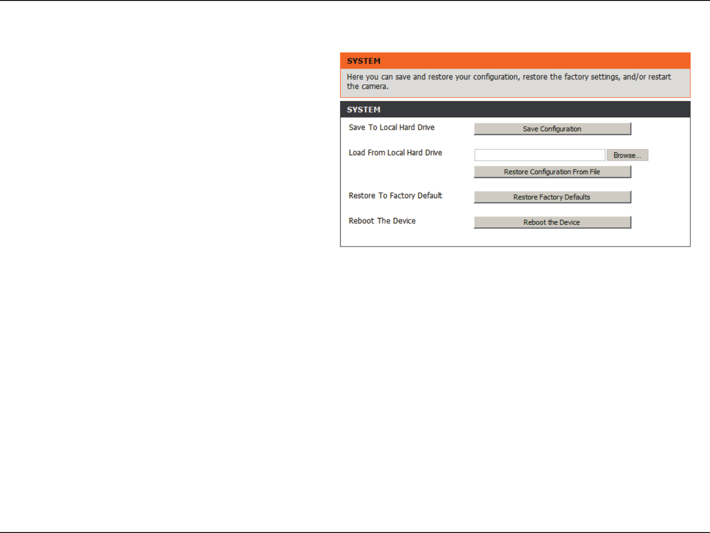
This section allows you to change the administrator’s password and
congure the server settings for your camera. You can also manage
the user account(s) that access to your camera.
Camera Name:
LED Control:
User Access Control:
Snapshot URL
Authentication:
Add User Account:
User List:
Specity a name for your camera
Select Normal to enable the LED on the front of
the device, or select off to disable the LED.
Select Enable to enable user access control or
Disable to allow only the administrator account
to access the camera.
Select Enable to allow access to the current
camera snapshot via the web address indicated.
Create new user for accessing the video image.
Enter the user name, password, and password
conrmation, and click Add. A maximum of 8
user accounts can be added into the user list.
Displays the account names of authorized users.
31D-Link DCS-930 User Manual
Section 3 - Configuration
Maintenance > System
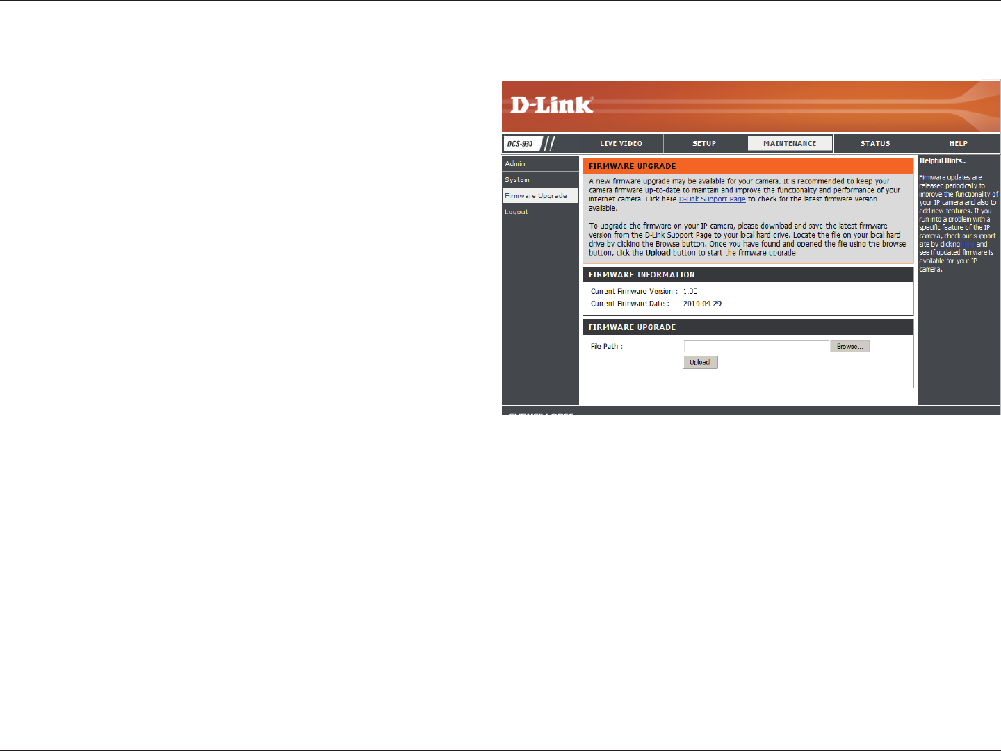
This section allows you to save and restore your conguration,
restore the factory settings, and/or restart the camera.
32D-Link DCS-930 User Manual
Section 3 - Configuration
Maintenance > Firmware Upgrade
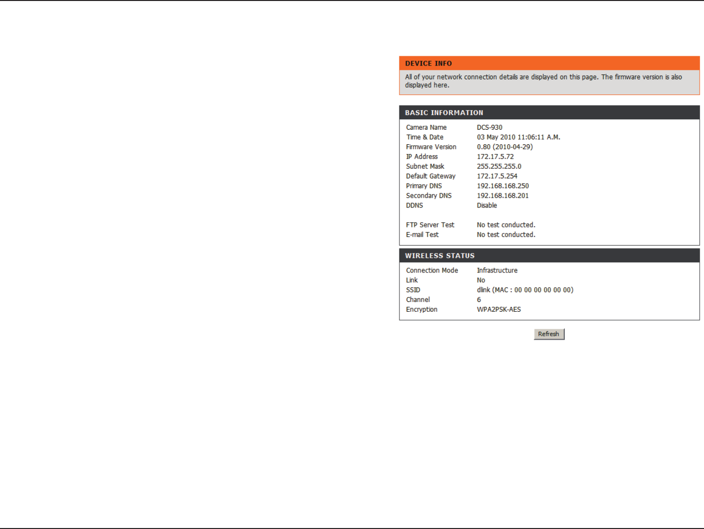
Your current rmware version and date will be displayed on your
screen. You may go to the D-Link Support Page to check for the
latest rmware versions available.
To upgrade the rmware on your DCS-930, please download
and save the latest rmware version from the D-Link Support
Page to your local hard drive. Locate the le on your local hard
drive by using the Browse button. Then, open the le and click
the “Upload” button to start the rmware upgrade.
DCS-930L_A2
DCS-930_A2
33D-Link DCS-930 User Manual
Section 3 - Configuration
Status > Device Info
This section displays all the details information about your
device and network settings.
34D-Link DCS-930 User Manual
Section 3 - Configuration
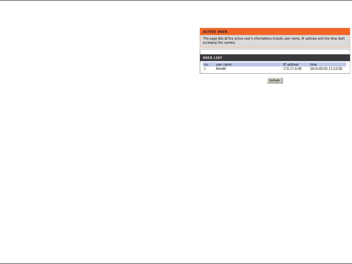
Status > Active User
This page lists all the active user’s information including the User
Name, IP address, and the time that camera access began.

35D-Link DCS-930 User Manual
Section 3 - Configuration
D-Link’s DCS-930 is a versatile and cost effective Network Camera for video monitoring. It can also serve as a powerful surveillance
system in security applications. The DCS-930 can be used with any wired or 802.11n wireless router. This section explains how to view
the camera from either the Internet or from inside your internal network.
Materials Needed:
• 1 DCS-930 Network Camera
• 1 Ethernet Cable
• A Wired or Wireless router such as the D-Link DI-624 Wireless Router
• Ethernet based PC for system conguration
Setting Up the DCS-930 For Use Behind a Router
Installing a DCS-930 Network Camera on your network is an easy 4–step procedure:
1. Assign a Local IP Address to Your Network Camera
2. View the Network Camera Using Your Internet Explorer Web Browser
3. Access the Router with Your Web Browser
4. Open Virtual Server Ports to Enable Remote Image Viewing
This section is designed to walk you through the setup process for installing your camera behind a router and enable remote video
viewing. For the basic setup of the DCS-930, follow the steps outlined in the Quick Installation Guide.
Using & Conguring the DCS-930
DCS-930_A2
DCS-930_A2
DCS-930_A2
DCS-930_A2
DCS-930_A2
DCS-930_A2
DCS-930_A2
36D-Link DCS-930 User Manual
Section 3 - Configuration
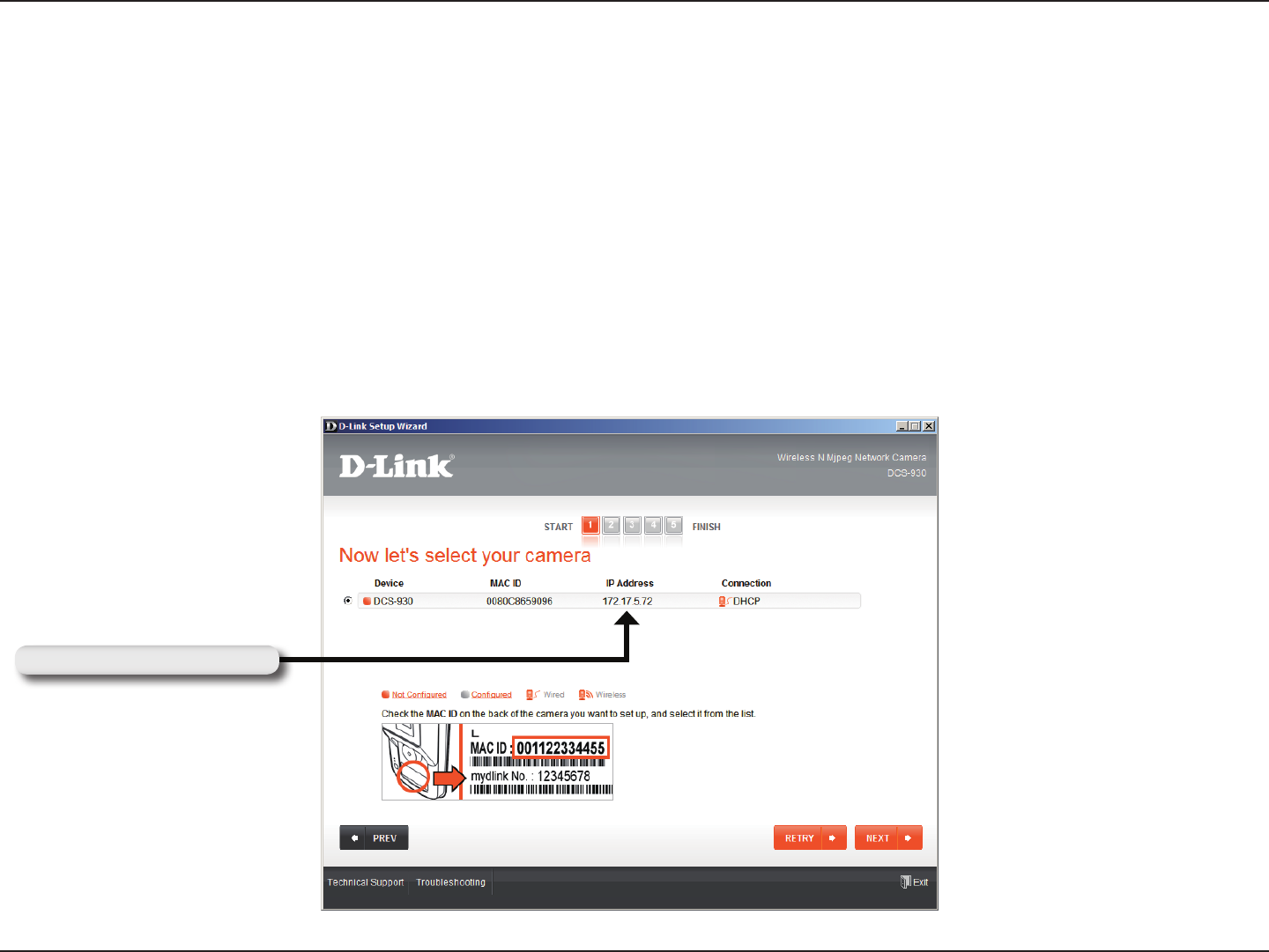
Run the Setup Wizard program from the CD included with the DCS-930. Follow the steps in the Quick Installation Guide to congure the
DCS-930. The camera will be assigned a local IP Address that allows it to be recognized by the router. Write down this IP Address for
future reference.
1. Assign a Local IP Address to Your Camera
After you have completed the setup of the DCS-930 outlined in the Quick Installation Guide you will have an operating camera that has
an assigned IP Address. Because you are using a router to share the Internet with one or more PCs, the IP Address assigned to the
Network Camera will be a local IP Address. This allows viewing within your Local Area Network (LAN) until the router is congured to
allow remote viewing of the camera over the Internet.
This is the IP Address assigned to your camera (192.168.0.120 is only an example). You will probably have a different IP Address.
Your Camera’s IP Address
DCS-930L_A2
DCS-930_A2
DCS-930_A2
37D-Link DCS-930 User Manual
Section 3 - Configuration
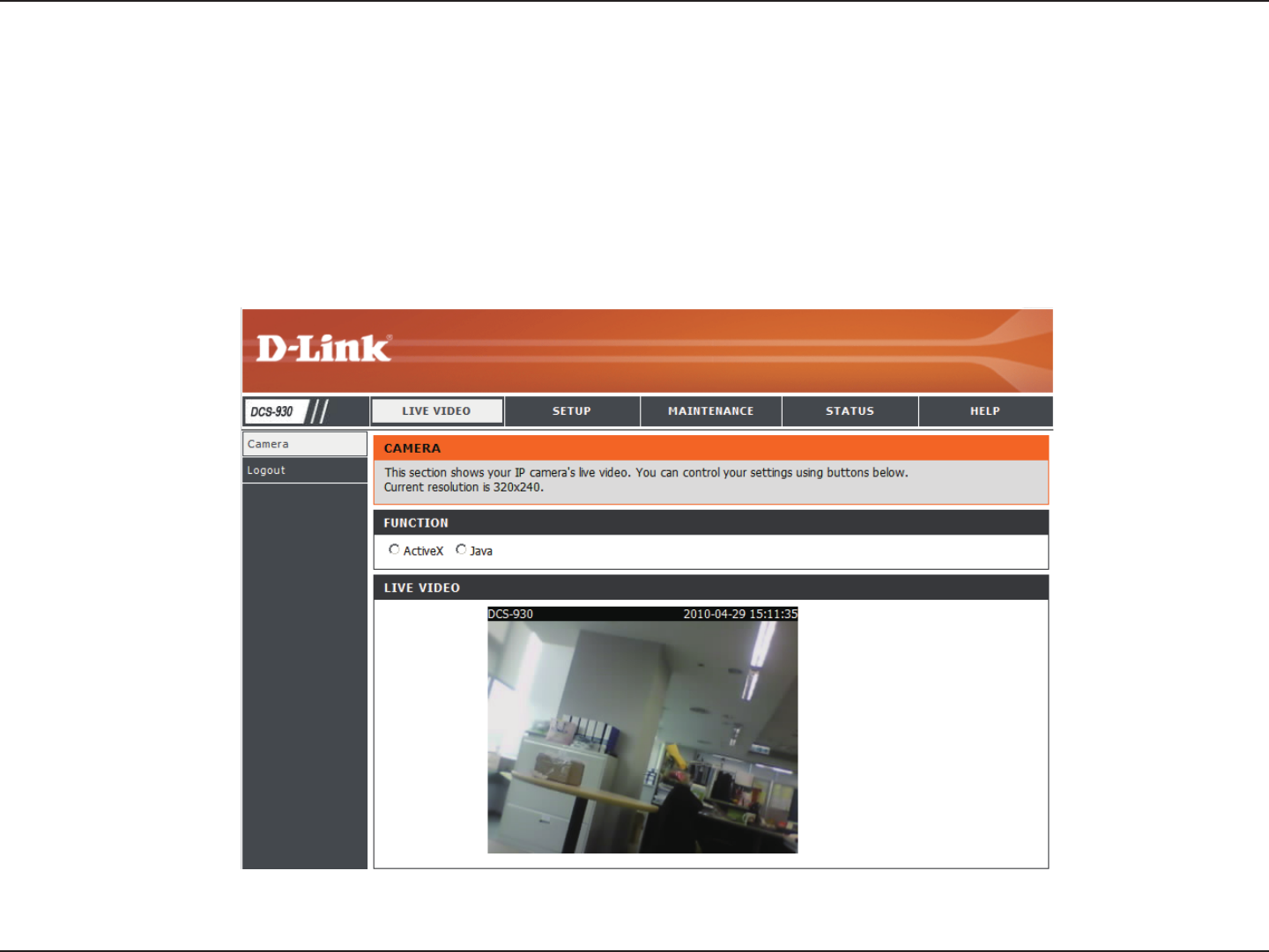
Run your Internet Explorer Web browser. In the address bar, type in the IP Address that was assigned to the Network Camera by the
Installation Wizard program. The DCS-930 Home Page appears with a window displaying live video from the camera. You are able to
view this screen from any PC running Internet Explorer on your LAN.
Click on the Conguration button on the left side of the display. Scroll to the bottom of the Network Conguration page to display the ports
used by HTTP and Streaming video.
2. View the Network Camera Using Your Internet Explorer Web Browser
DCS-930_A2

56D-Link DCS-930 User Manual
Appendix C - Technical Specifications
Technical Specications
SYSTEM REQUIREMENTS
• Operating System: Microsoft Windows XP, Vista, Windows 7
• Internet Explorer 6 or above , Firefox 3.5 or above, Safari 4
NETWORKING PROTOCOL
• IPV4, ARP, TCP, UDP, ICMP
• DHCP Client
• NTP Client (D-Link)
• DNS Client
• DDNS Client (Dyndns and D-Link)
• SMTP Client
• FTP Client
• HTTP Server
• PPPoE
• UPnP Port Forwarding
• LLTD
• UPnP-X1
BUILT-IN NETWORK INTERFACE
• 10/100BASE-TX Fast Ethernet
• 802.11b/g/n WLAN
WIRELESS CONNECTIVITY
• 802.11b/g/n Wireless with WEP/WPA/WPA2 security
WIRELESS TRANSMIT OUTPUT POWER
• 16 dbm for 11b, 12 dbm for 11g,
12 dbm for 11n (typical)
SDRAM
• 32 MB
FLASH MEMORY
• 4 MB
RESET BUTTON
• Reset to factory default
VIDEO CODECS
• MJPEG
• JPEG for still images
VIDEO FEATURES
• Adjustable image size and quality
• Time stamp and text overlay
• Flip and Mirror
RESOLUTION
• 640 x 480 at up to 20 fps
• 320 x 240 at up to 30 fps
• 160 x 120 at up to 30 fps

57D-Link DCS-930 User Manual
Appendix C - Technical Specifications
LENS
• Focal length: 5.01 mm, F2.8
SENSOR
• VGA 1/5 inch CMOS Sensor
MINIMUM ILLUMINATION
• 1 lux @ F2.8
VIEW ANGLE
• Horizontal: 45.3°
• Vertical: 34.5°
• Diagonal: 54.9°
DIGITAL ZOOM
• Up to 4x
3A CONTROL
• AGC (Auto Gain Control)
• AWB (Auto White Balance)
• AES (Auto Electronic Shutter)
POWER
• Input: 100-240 V AC, 50/60 Hz
• Output: 5 V DC, 1.2 A
• External AC-to-DC switching power adapter
DIMENSIONS (W X D X H)
• Including the bracket and stand:
65.8 x 65 x 126 mm
• Camera only:
27.2 x 60 x 96 mm
WEIGHT
• 76.9 g (without bracket and stand)
MAX POWER CONSUMPTION
• 2 W
OPERATION TEMPERATURE
• 0 ˚C to 40 ˚C (32 ˚F to 104 ˚F)
STORAGE TEMPERATURE
• -20 ˚C to 70 ˚C (-4 ˚F to 158 ˚F)
HUMIDITY
• 20-80% RH non-condensing
EMISSION (EMI), SAFETY & OTHER CERTIFICATIONS
• FCC Class B
• IC
• C-Tick
• CE
FCC Notices
This device complies with Part 15 of the FCC Rules. Operation is subject to the following
two conditions: (1) this device may not cause harmful interference, and (2) this device
must accept any interference received, including interference that may cause undesired
operation.
CAUTION: Change or modification not expressly approved by the party responsible
for compliance could void the user’s authority to operate this equipment.
This equipment has been tested and found to comply with the limits for a Class B
digital device, pursuant to Part 15 of the FCC Rules. These limits are designed to provide
reasonable protection against harmful interference in a residential installation. This
equipment generates, uses and can radiate radio frequency energy and, if not installed
and used in accordance with the instructions, may cause harmful interference to radio
communications. However, there is no guarantee that interference will not occur in a
particular installation. If this equipment does cause harmful interference to radio or
television reception, which can be determined by turning the equipment off and on, the
user is encouraged to try to correct the interference by one or more of the following
measures:
--Reorient or relocate the receiving antenna.
--Increase the separation between the equipment and receiver.
--Connect the equipment into an outlet on a circuit different from that to which the receiver
is connected.
--Consult the dealer or an experienced radio/TV technician for help.
CAUTION:
Any changes or modifications not expressly approved by the grantee of this device could
void the user's authority to operate the equipment.
RF exposure warning
This equipment must be installed and operated in accordance with provided instructions
and the antenna(s) used for this transmitter must be installed to provide a separation
distance of at least 20 cm from all persons and must not be co-located or operating in
conjunction with any other antenna or transmitter. End-users and installers must be
provide with antenna installation instructions and transmitter operating conditions for
satisfying RF exposure compliance."
Canada Notices
Industry Canada regulatory information
Operation is subject to the following two conditions: (1) this device may not cause
interference, and (2) this device must accept any interference, including interference
that may cause undesired operation of the device.
The user is cautioned that this device should be used only as specified within this
manual to meet RF exposure requirements. Use of this device in a manner
inconsistent with this manual could lead to excessive RF exposure conditions.