D Link DI-624 Wireless 2.4GHz mini-PCI Mobile Module User Manual Manual
D Link Corporation Wireless 2.4GHz mini-PCI Mobile Module Manual
UserManual.wiki
>
D Link
>
DI 624 User Manual
Manual
Navigation menu
Upload a User Manual
Namespaces
Wiki Guide
HTML
PDF
Info
Views
User Manual
Discussion / Help
Navigation
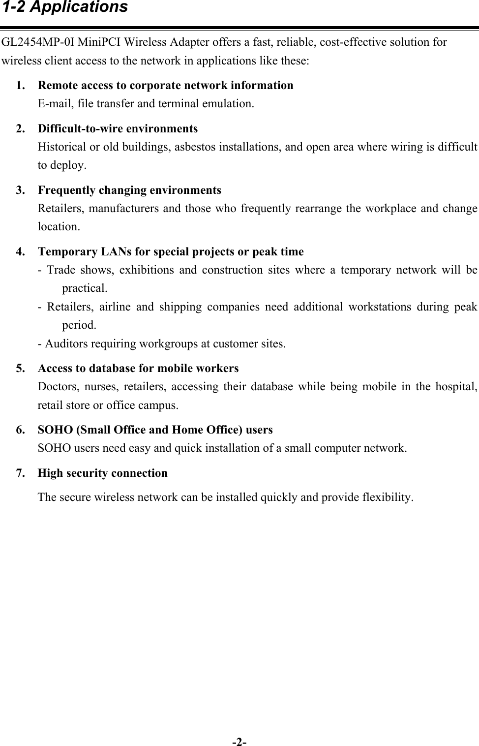
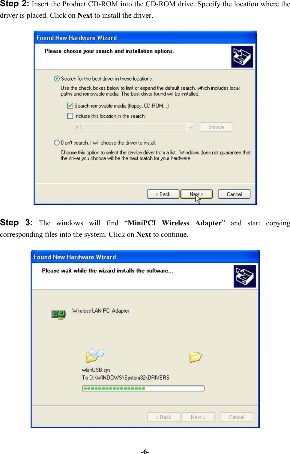
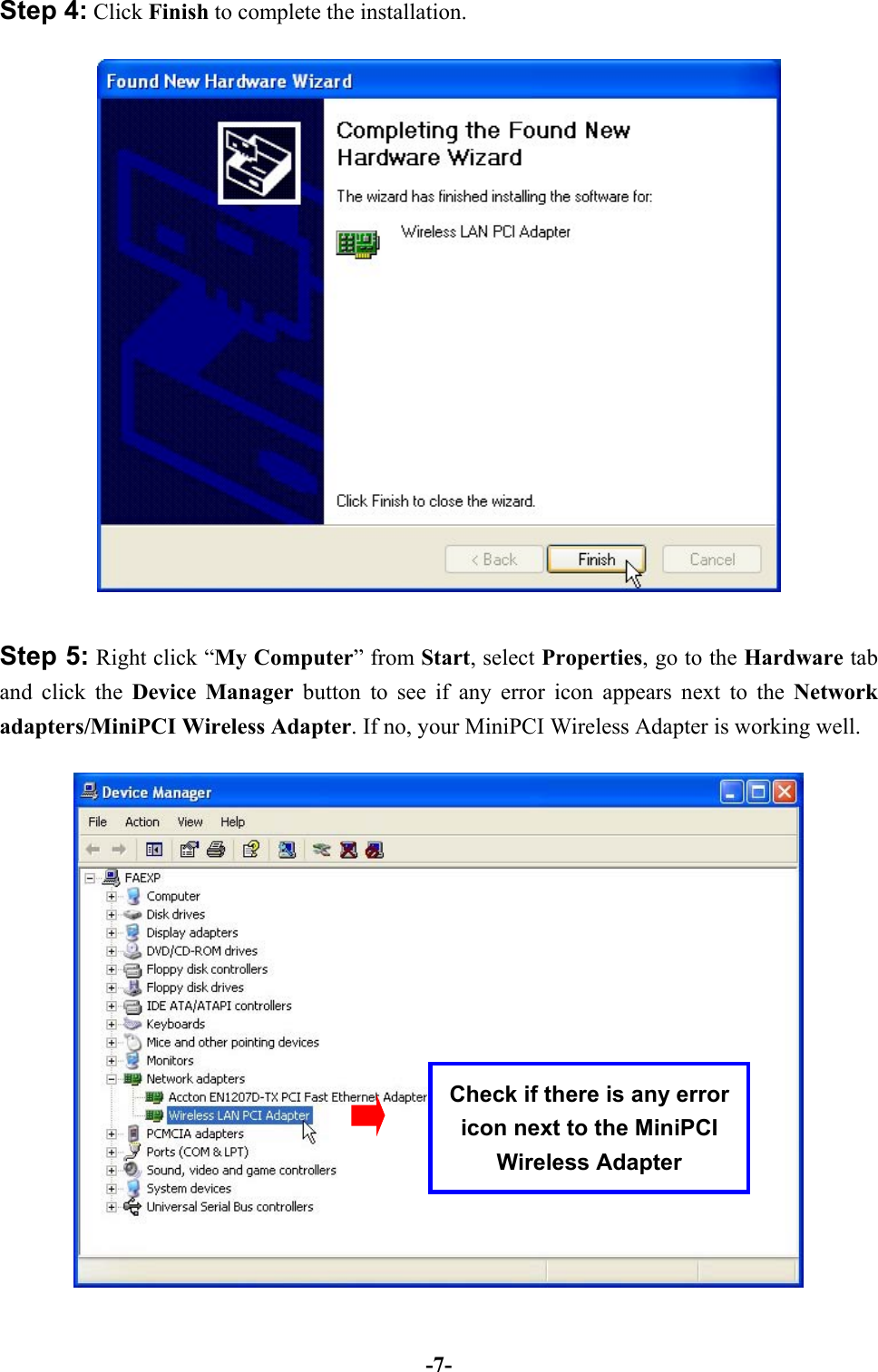
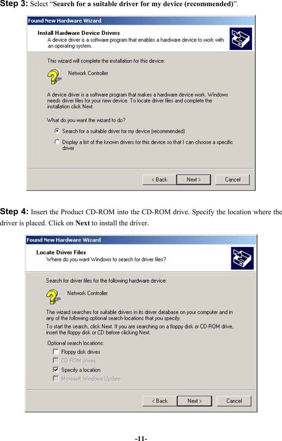
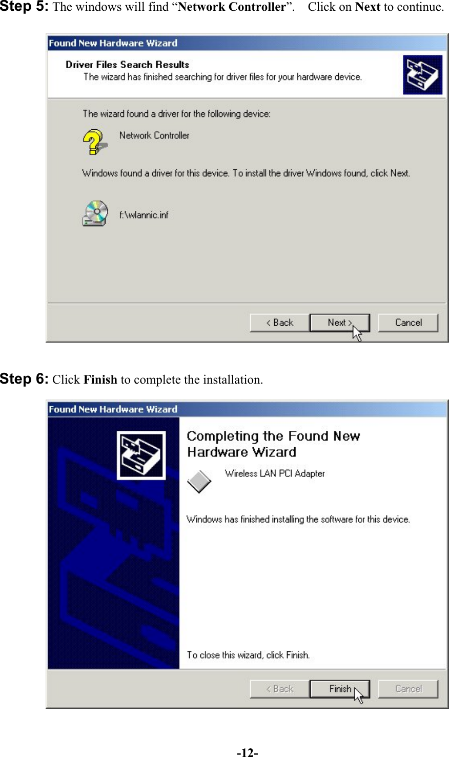
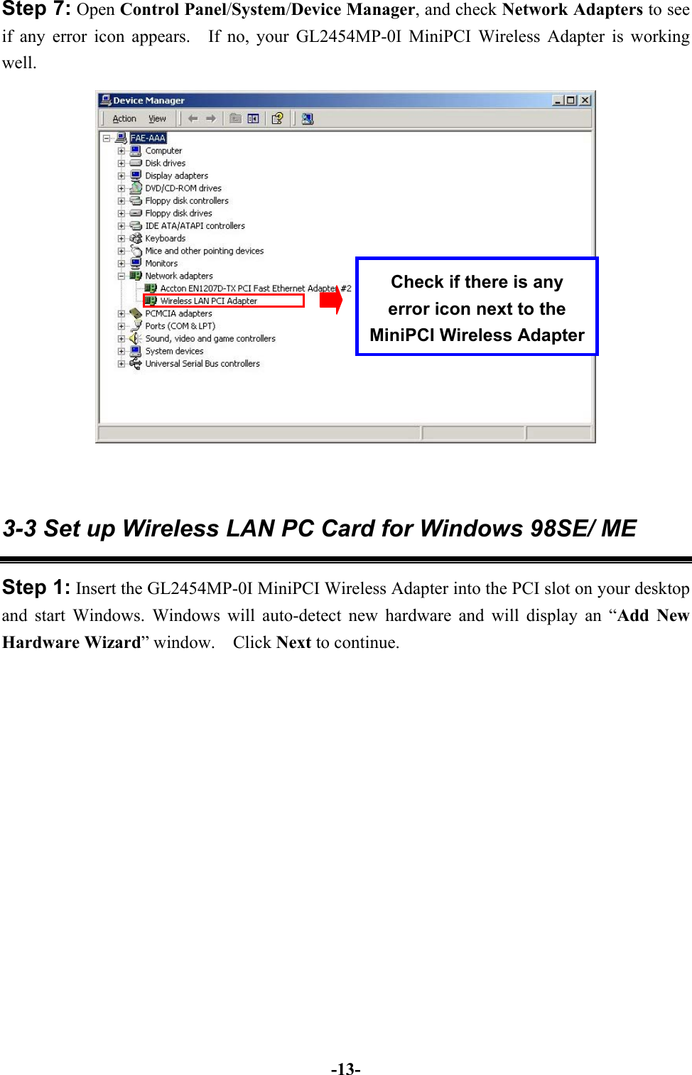
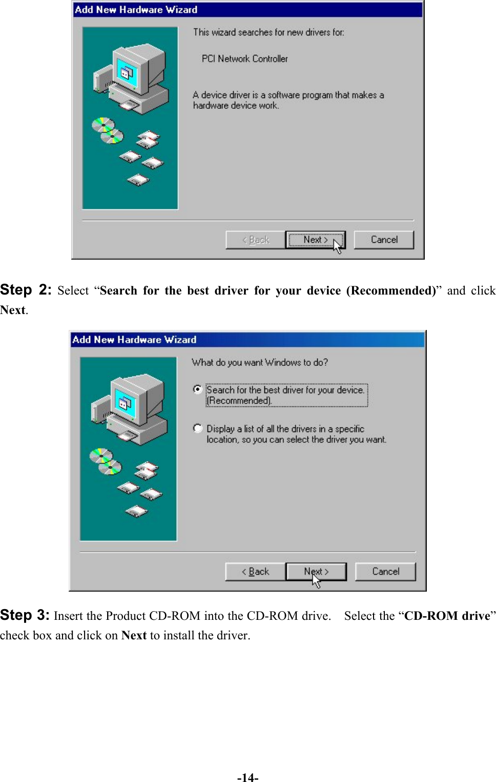
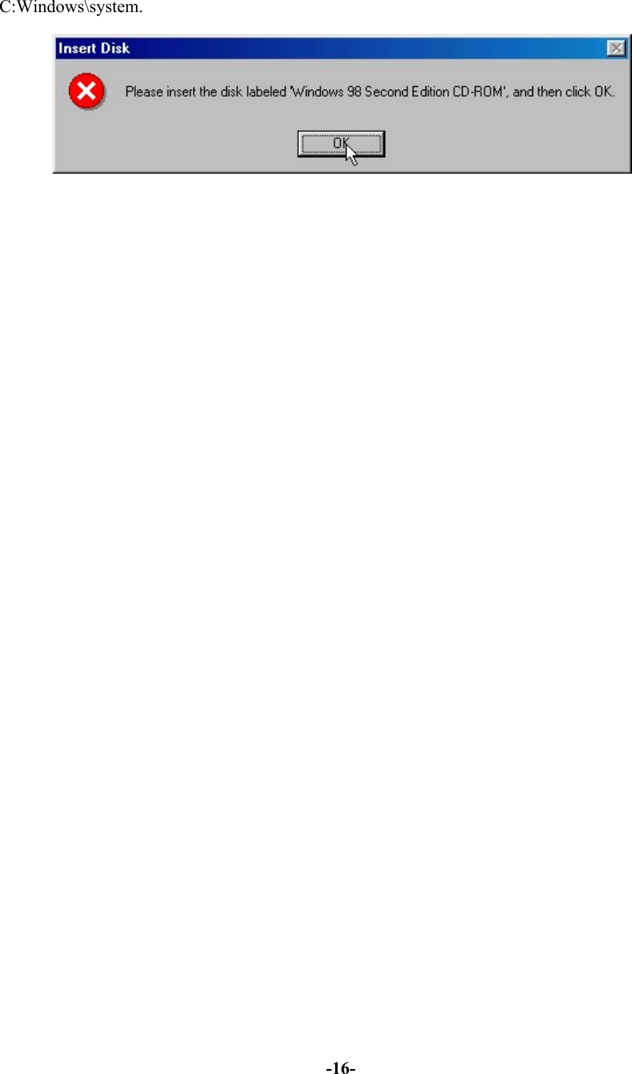
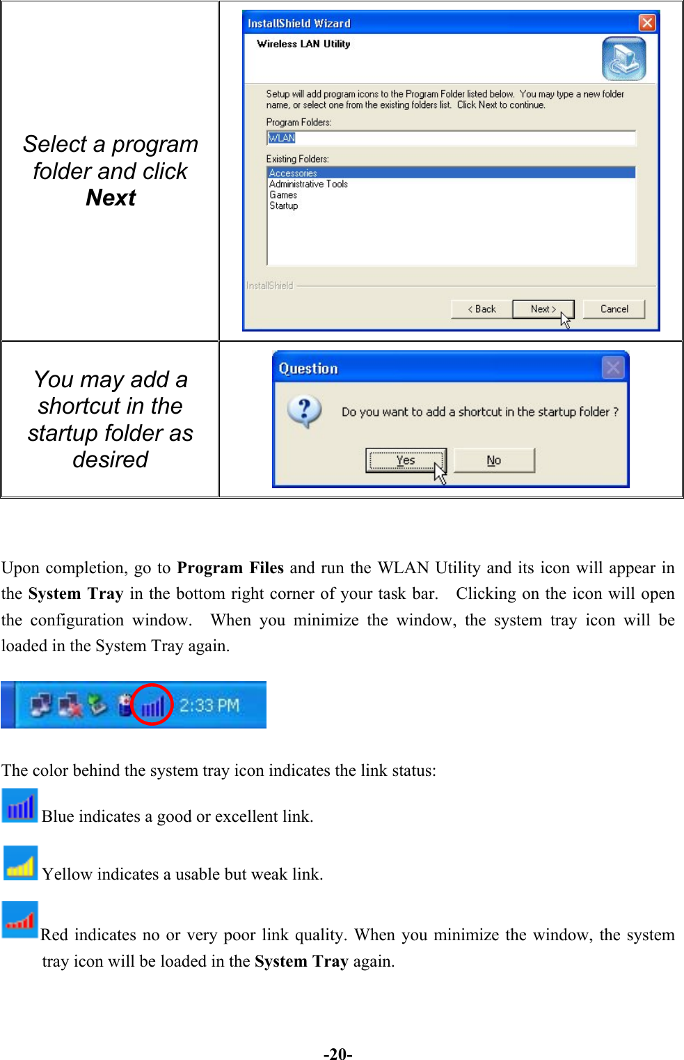
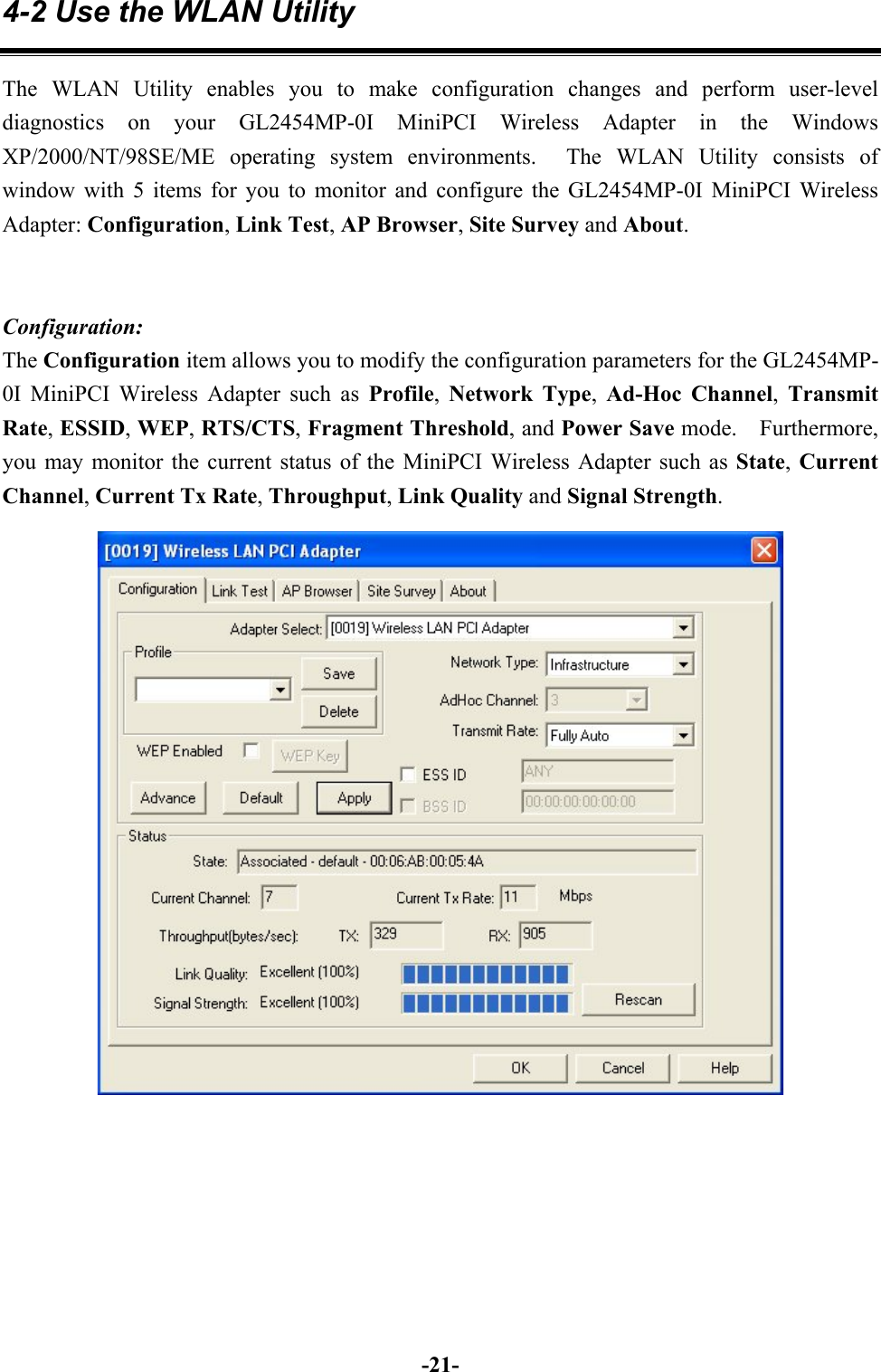
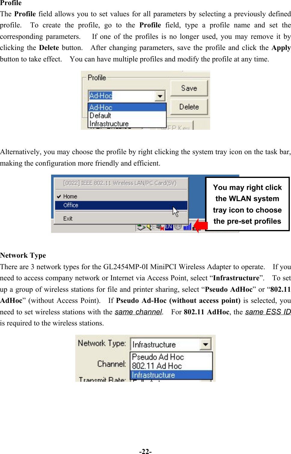
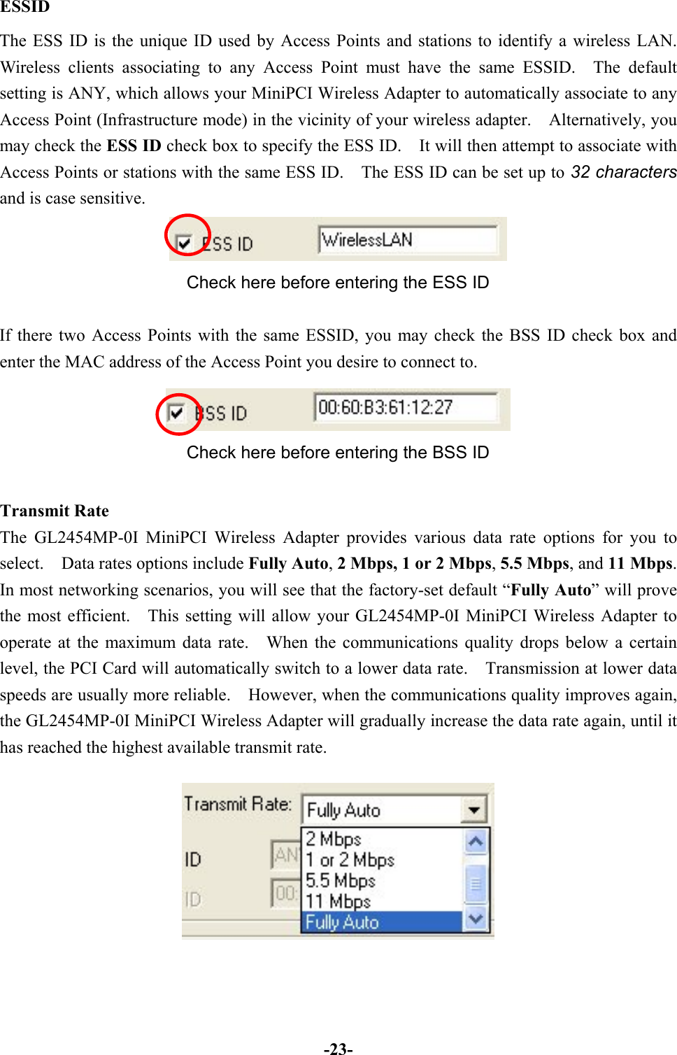
![-15-Step 4: The Windows will find “MiniPCI Wireless Adapter”. Click Next to continue.Step 5: Once the [Please insert the disk labeled ‘Windows 98 Second Edition CD-ROM/MECD-ROM”, and then click OK] window appears, inset enter the path corresponding to theappropriate drives and click OK. Usually these files can be found at C:Windows or](https://usermanual.wiki/D-Link/DI-624/User-Guide-294909-Page-18.png)