D Link DIR320A1 802.11g Wireless Cable/DSL Internet Gateway w/USB User Manual Users manual4
D Link Corporation 802.11g Wireless Cable/DSL Internet Gateway w/USB Users manual4
D Link >
Contents
- 1. Users manual1
- 2. Users manual2
- 3. Users manual3
- 4. Users manual4
Users manual4
Section 3 – Configuration
D-Link DIR-320 User Manual 39
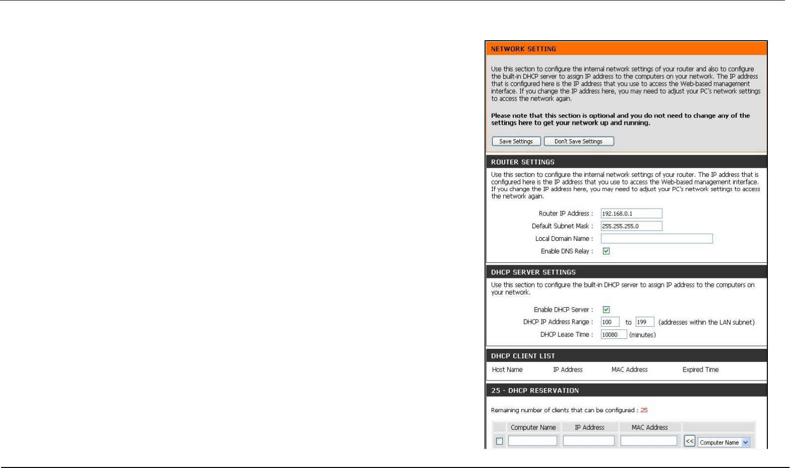
LAN Setup
Use the Network Settings menu to configure Router LAN IP Settings and DHCP
Server Settings. When you are finished, click the Save Settings button at the top of
the window.
Section 3 – Configuration
D-Link DIR-320 User Manual 40
Router IP Settings
Router Settings
This section is used to configure the internal network settings of the
Router. This IP address is private to your internal network and cannot be
seen on the Internet. The default Router IP Address is 192.168.0.1 and
the Default Subnet Mask is 255.255.255.0. The Local Domain Name is
for the local Domain set on your network, if you have given it a name
previously. This field is for your personal use and unnecessary for proper
configuration of this window.
In addition, the Router can be configured to relay DNS from your ISP or
another available service to workstations on your LAN. When Enable
DNS Relay is checked, the Router will accept DNS requests from hosts
on the LAN and forward them to the ISP (or alternative) DNS servers.
Alternatively, you may also disable the DNS relay and configure hosts on
your LAN to use DNS servers directly. Most clients using the Router for
DHCP service on the LAN and are using DNS servers on the ISP’s
network, will leave DNS relay enabled.
Section 3 – Configuration
D-Link DIR-320 User Manual 41
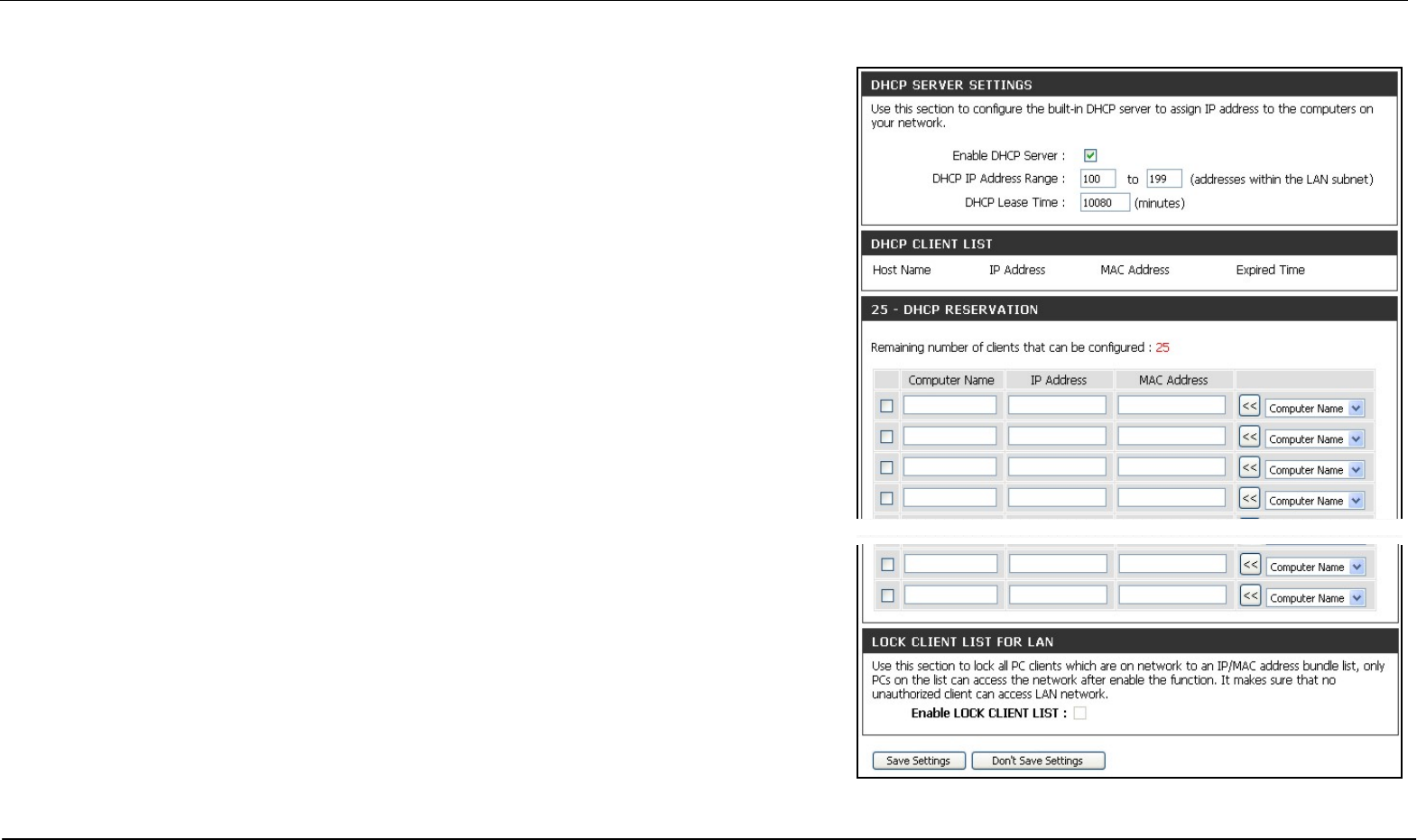
LAN DHCP Server Settings
DHCP Server Settings
Dynamic Host Configuration Protocol (DHCP) allows the gateway to automatically
obtain the IP address from a DHCP server on the service provider’s network. The
service provider assigns a global IP address from a pool of addresses available to the
service provider. Typically the IP address assigned has a long lease time, so it will likely
be the same address each time the Router requests an IP address. If DHCP is not
enabled on the Router, it is necessary for the user to assign a static IP address to each
computer on your LAN.
To set up DHCP for your LAN, first enable the Router as a DHCP server by clicking the
Enable DHCP Server radio button in the window above. The next step is to set a range
of IP addresses that you wish to allot to the devices on your LAN by entering a starting
and ending number of addresses within the LAN subnet in the DHCP IP Address
Range. This may be in a range from 2 to 254 (192.168.0.2 – 192.168.0.254).
Computers on your LAN will have an IP address within this range then automatically
assigned to them. Finally, choose the DHCP Lease Time, which is the time the Server
will set for devices using DHCP to re-request an IP Address. Clients authorized for
DHCP will be listed in the Dynamic DHCP Client List near the bottom of the window.
Click Save Settings to implement information set in this table. The DHCP Server is
enabled by default. DHCP may also be statically configured as well. This method allows
the router to assign the same IP address information to a specific computer on the
network, defined by its MAC address. This computer will get the same DHCP
implemented IP address information every time the computer is turned on and this IP
address will be specific to that computer’s IP address on the local network. No other
computer can be assigned this address. This is useful for computers on the LAN that
are hosting applications such as HTTP or FTP. First, the user must enter the Host
Name and the IP Address for that computer in the spaces provided. Next, the user
must enter the MAC Address of the computer in the space provided. Click Save
Settings to implement these static settings.
Section 3 – Configuration
D-Link DIR-320 User Manual 42
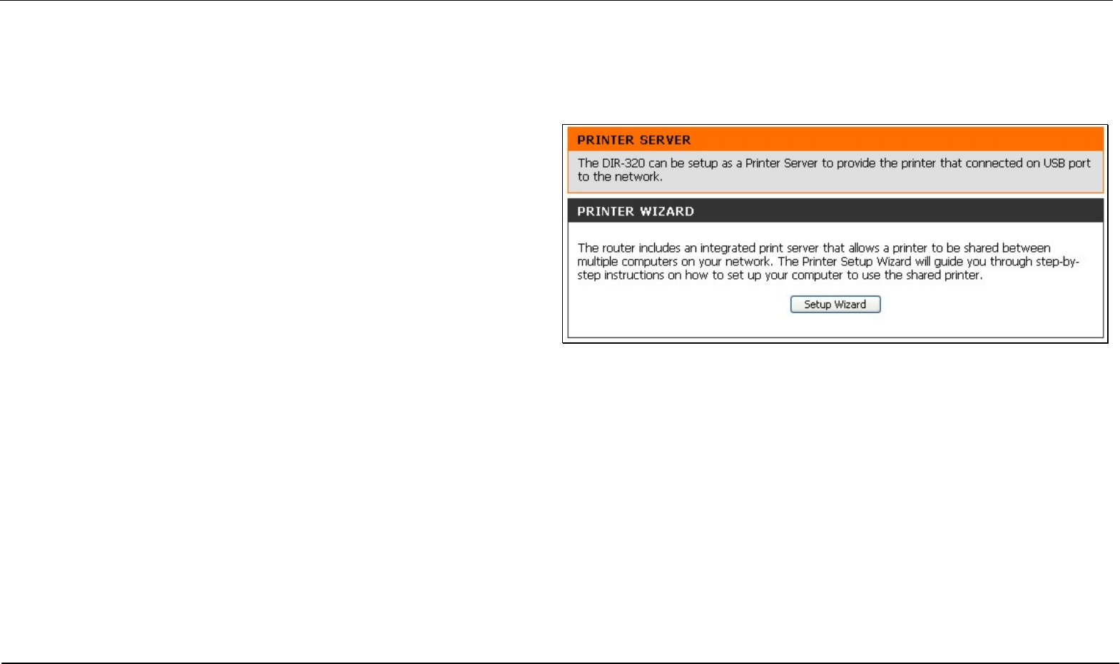
Printer Setup
Printer Setup Wizard
Use the Printer Setup Wizard to configure the Router’s USB Printer
connection. To establish the connection to a USB equipped printer, click
the Printer Setup link to view the Printer Setup Wizard launch menu.
Follow the instructions below to install the printer driver on your
computer. Some printers, especially very recent release printers, might
require the Printer CD-ROM containing the printer driver that came with
the printer. This procedure must be followed by any computer that will
use the printer.
To use a printer connected to the USB printer port on the DIR-320:
1. Have the CD-ROM with the printer driver available, it might be
needed for the installation.
2. Power on the printer; follow the instructions included with the
printer to plug in the power cable and turn the power on.
3. Complete the USB connection from the DIR-320 USB to the USB
port on the printer. Check the LED indicator on the DIR-320 front
panel for the USB connection to make sure a physical connection
is established.
4. From the Printer Setup menu, click the Setup Wizard button to
launch the Printer Setup Wizard.
Section 3 – Configuration
D-Link DIR-320 User Manual 43
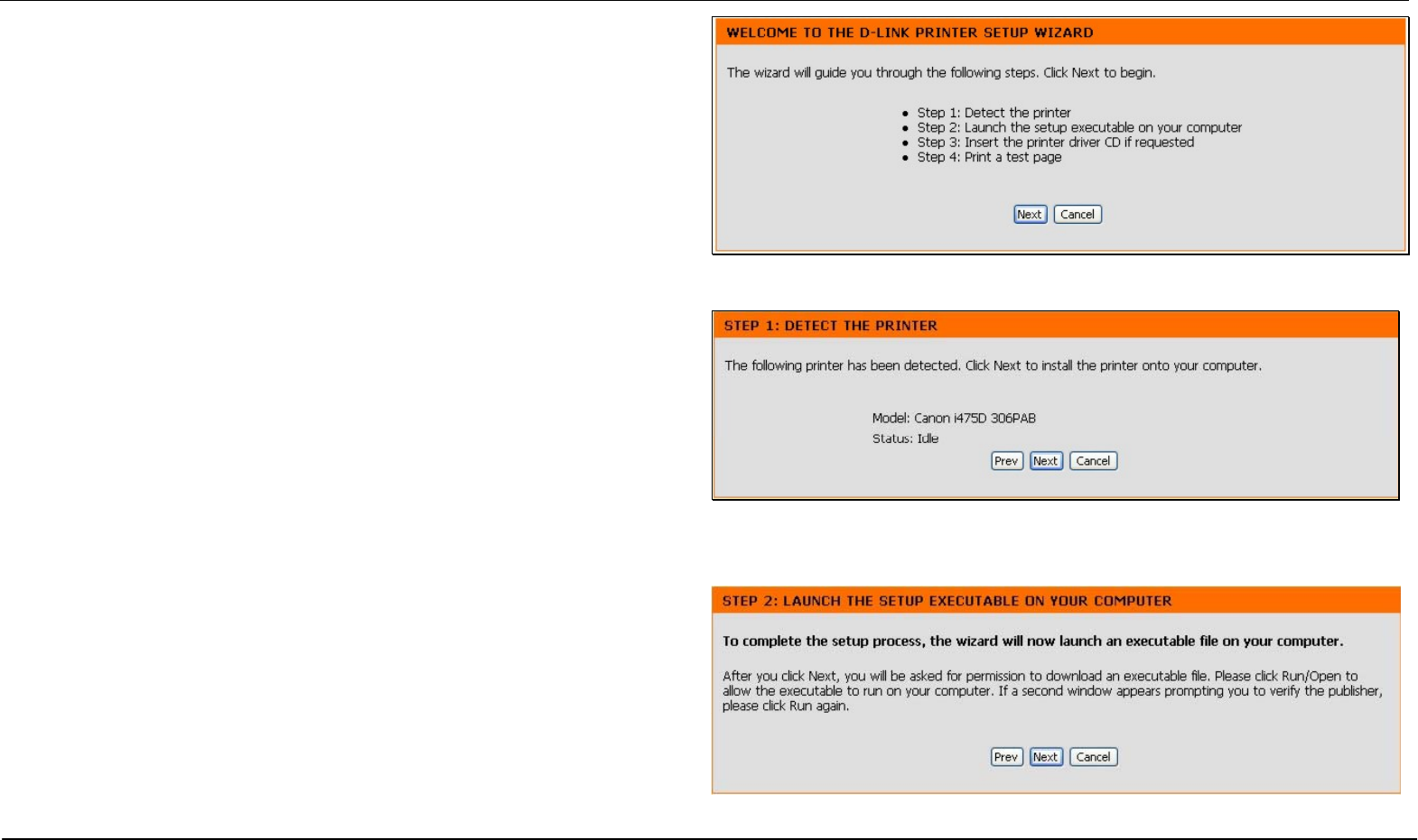
The first Printer Setup Wizard menu lists the steps used for intallation.
Click the Next button to detect the printer.
The printer should be detected immediately. The model name will be
displayed if detected. If no printer is detected a warning tells you the
printer installation cannot be completed. Check the cable connections
and make sure the printer is powered on. Click Next if a printer is
detected.
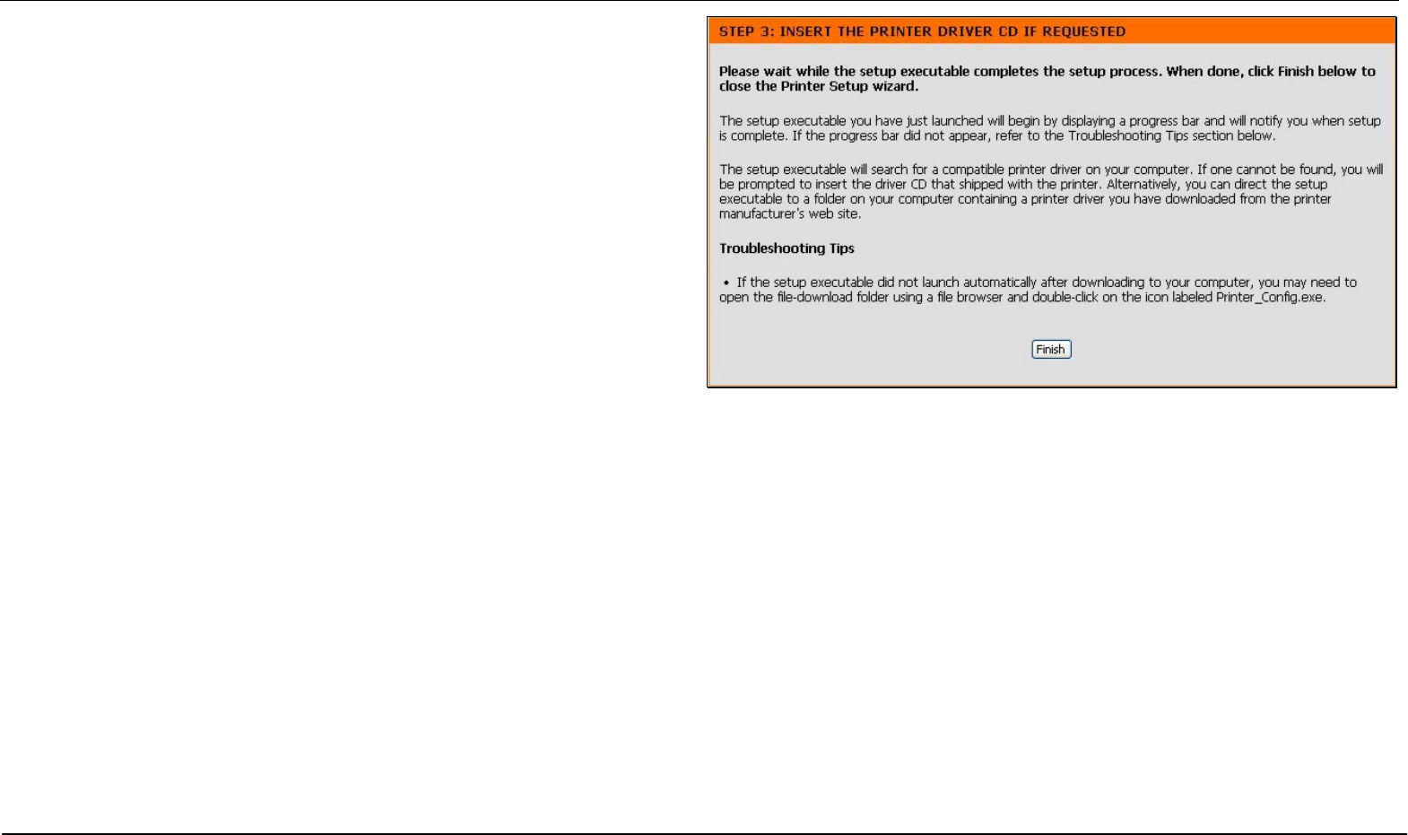
It is now necessary to install the correct printer driver on your computer.
Click the Next button to launch the file.
Section 3 – Configuration
D-Link DIR-320 User Manual 44
A setup will launch or attempt to launch on your computer. Often the
browser settings prevent the file from launching until permission is
granted. This file must be executed to install the printer driver. In
Windows Internet Explorer permission can be granted to launch
downloded application. See the example from Windows Internet
Explorer as seen in XP below. If asked to insert the CD-ROM containing
the printer driver, insert the CD-ROM in the CD-ROM drive of your
computer and install the printer driver according to the instructions for
the printer.
Section 3 – Configuration
D-Link DIR-320 User Manual 45
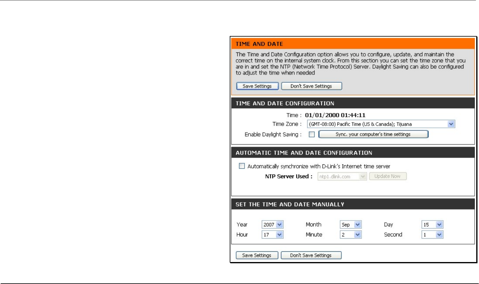
Time and Date
The system time is the time used by the DIR-320 for scheduling
services. You can configure, update, and maintain the time on the
internal system clock.
To configure system time on the Router, select the method used to
maintain time. The options available include the default
Automatically synchronize with D-Link’s Internet timeserver
using Simple Network Time Protocol (SNTP), to use your
computer’s system clock, deselect the Automatic option and click the
Sync. your computer’s time settings button. Time can be sett
manually using the manual pull-down menus at the bottom of the
menu.
Click on the Save Settings button to save and apply the new time
configuration.
Section 3 – Configuration
D-Link DIR-320 User Manual 46
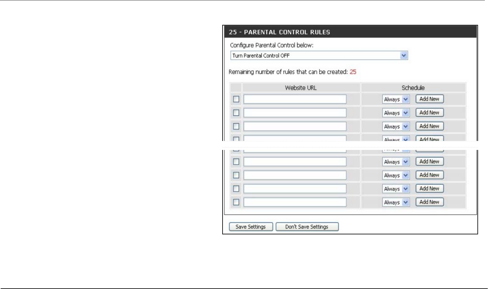
Parental Control
Use this menu to deny access to specified websites and to set
Internet access time periods.
URL or Uniform Resource Locator is a specially formatted text
string that uniquely defines an Internet website. This menu will
allow users to block computers on the LAN from accessing
certain URLs.
To configure this menu for URL blocking, enter the website’s
address into the Website URL field, select the desired Schedule
and click the Add New button for that entry. Schedules can be
created using the Schedules menu in the Maintenance directory.
Click on the Save Settings button to save and apply the new web
access control configuration.
Section 3 – Configuration
D-Link DIR-320 User Manual 47
Advanced Setup
The Advanced directory tab offers several configuration menus
including Port Forwarding, Application Rules, Access Control,
Firewall & DMZ, Advanced Wireless, Advanced Network,
Routing, QoS Engine, Guest Zone, and Traffic Management.
Click the corresponding link in the left panel of the window. Port
Forwarding is the first menu listed and the first to appear when
accessing the Advanced directory.
Section 3 – Configuration
D-Link DIR-320 User Manual 48
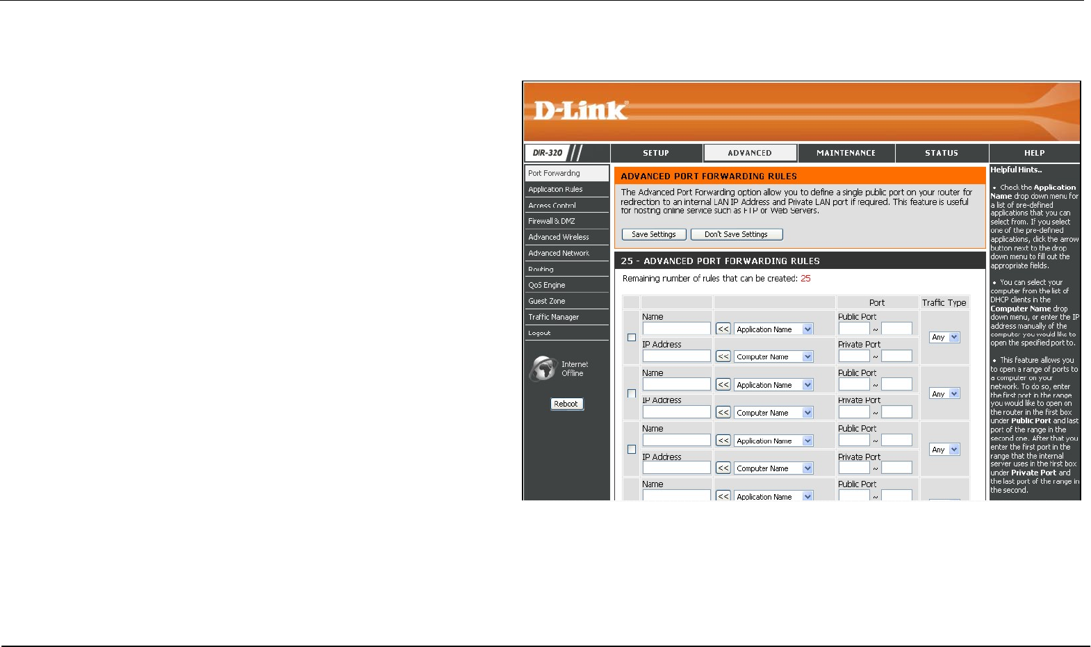
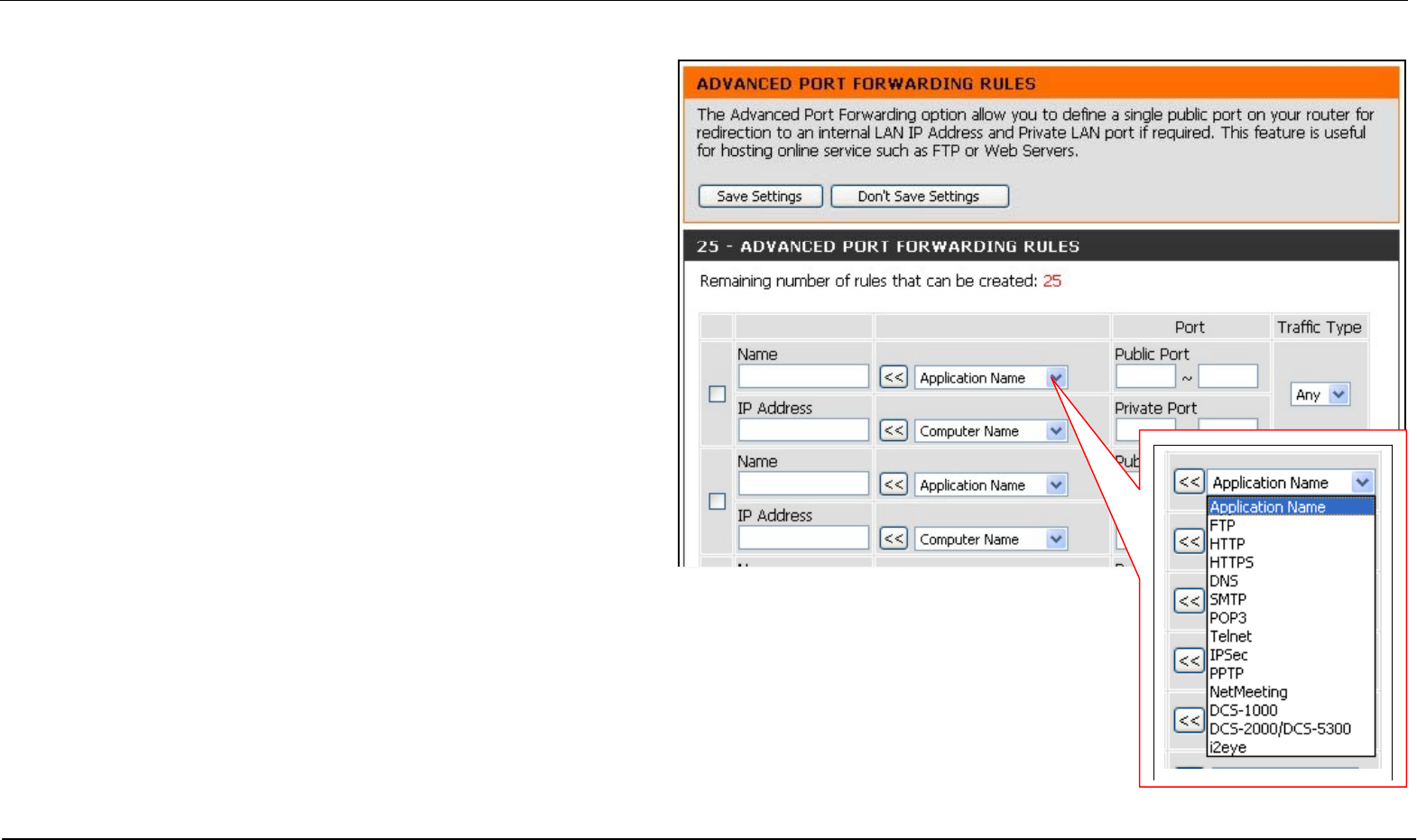
Port Forwarding
The Advanced Port Forwarding menu allows configuration for remote
users access to various services outside of their LAN through a
public IP address, such as FTP (File Transfer Protocol) or HTTPS
(Secure Web). After configuring the Router for these features, the
Router will redirect these external services to an appropriate server
on the users LAN. The Router has 13 pre-configured external
services already set, or manually set the port or port range used for
the rules.
To enable an already existing Port Forwarding Rule, click on its
corresponding checkbox and configure the appropriate fields listed
below. To configure other Port Forwarding Rules for the Router, use
the pull-down menus to select the computer or specify an IP
address, type the port or port range or select an application form the
pull-down menu, select the traffic type and click the Save Settings
button at the top of the window.
Section 3 – Configuration
D-Link DIR-320 User Manual 49
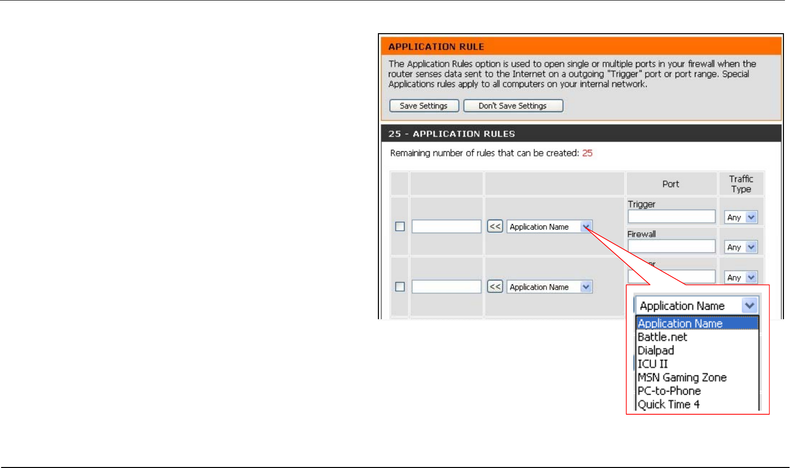
Application Rules
Use the Application Rules menu to configure applications that
require multiple connections, such as Internet Telephony, video
conferencing, and Internet gaming. The following window lists six
Special Applications that commonly use more than one connection.
To configure one of these applications, tick its corresponding
checkbox and then modify the fields listed below the following figure.
The user may add a new application by modifying the fields listed
and then clicking the Save Settings button at the top of the window.
To enable an already existing Application Rule, click on its
corresponding checkbox. To configure other Application Rules for the
Router, type the port or port range or select an application form the
pull-down menu, type a name for the rule and select the traffic type
and click the Save Settings button at the top of the window.
Section 3 – Configuration
D-Link DIR-320 User Manual 50
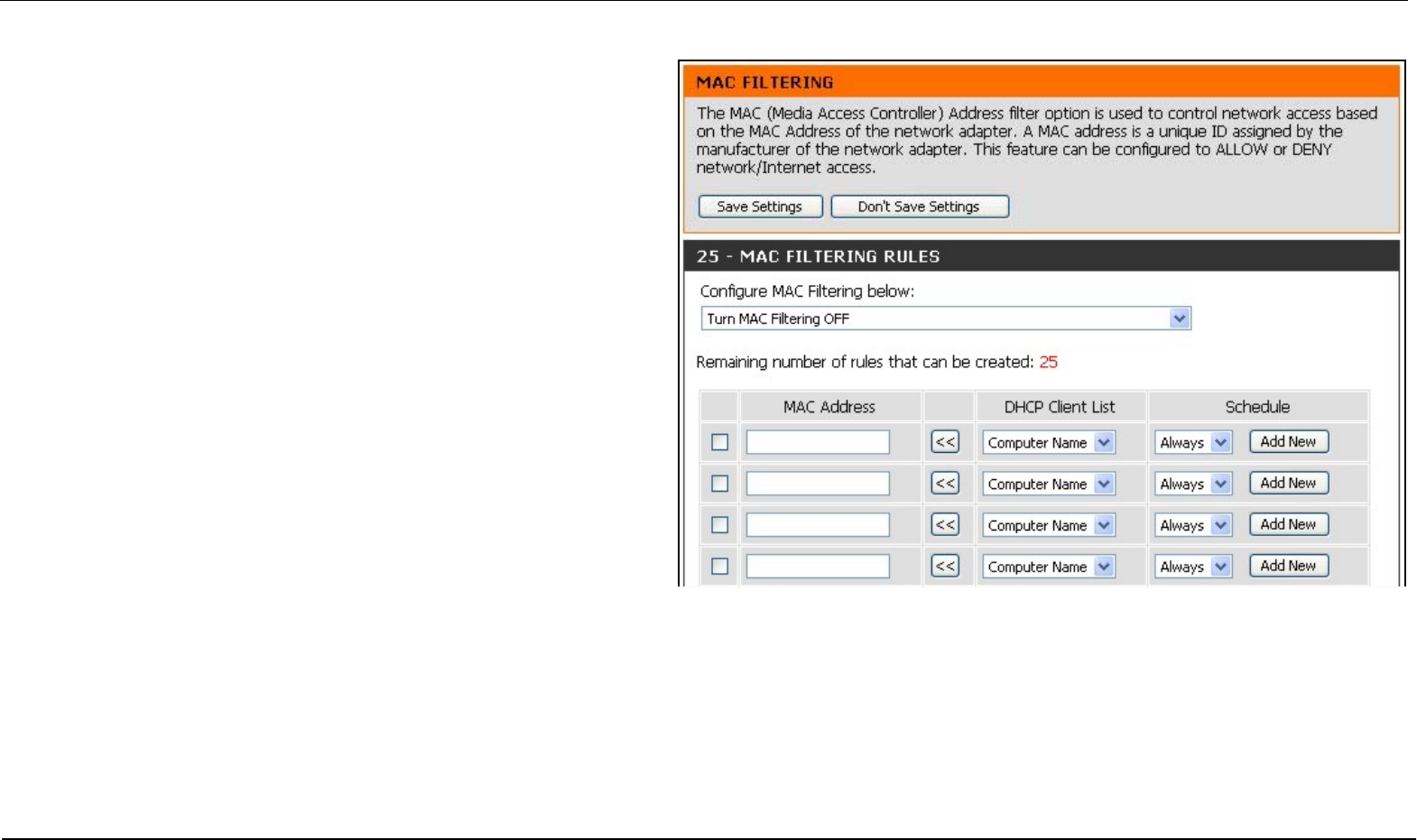
Access Control
Access Control, or MAC filtering, is a basic security measure that
should be used on any network that is exposed to a security risk. A
packet filter system examines data packets and scrutinizes them in
order to control network access. Filtering rules determine whether
packets are passed through the Router from either side of the
gateway. The rules are created and controlled by the network
administrator and can be precisely defined. These rules are used to
block access to the LAN from outside the network and/or to deny
access to the WAN from within the network.
MAC Filters
All computers are uniquely identified by their MAC (Media Access
Control) address. The following window will allow users to deny
computers access to the Internet or only allow certain computers
access to the Internet, based on their MAC address. To access this
window, click the Advanced tab along the top of the configuration
window, then the Access Control tab to the left hand side.
To configure MAC filters, manually enter a MAC address to be
filtered by ticking its corresponding checkbox and then configuring
the desired fields on the window above. Select Turn MAC Filtering
OFF, Turn MAC Filtering ON and ALLOW computers listed to access
the network, and Turn MAC Filtering ON and DENY computers listed
to access the network from the drop-down menu. When you are
finished, click the Save Settings button at the top of the window.
Section 3 – Configuration
D-Link DIR-320 User Manual 51
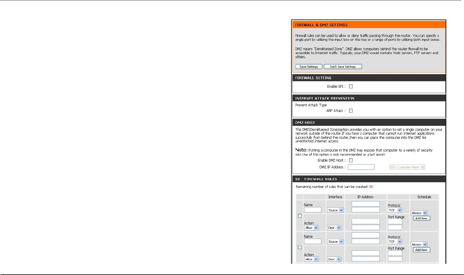
Firewall & DMZ
The Firewall & DMZ menu is used to define enforce specific predefined policies intended to
protect against certain common types of attacks.
A DoS "denial-of-service" attack is characterized by an explicit attempt by attackers to
prevent legitimate users of a service from using that service. Examples include: attempts to
"flood" a network, thereby preventing legitimate network traffic, attempts to disrupt
connections between two machines, thereby preventing access to a service, attempts to
prevent a particular individual from accessing a service, or, attempts to disrupt service to a
specific system or person. To enable this function, tick the Enable DoS Prevention
checkbox.
Firewall Rules
To configure rules for the firewall, modify the following fields and click the Save Settings
button at the top of the window to set the rule in the Routers memory. Newly configured
firewall rules will be displayed in the Firewall Rules List at the bottom of the window.
Internet Attack Prevention
This is used for ARP attacks. The router will drop ARP inquiry packets when it detects an
extraordinarily high volume of ARP requests.
DMZ Host
Firewalls may conflict with certain interactive applications such as video conferencing or
playing Internet video games. For these applications, a firewall bypass can be set up using
a DMZ IP address. The DMZ IP address is a “visible” address and does not benefit from the
full protection of the firewall function. Therefore it is advisable that other security
precautions be enabled to protect the other computers and devices on the LAN. It may be
wise to use isolate the device with the DMZ IP address from the rest of the LAN.
For example, if you want to use video conferencing and still use a firewall, you can place
the server in the DMZ. The IP address of this server will then be the DMZ IP address. You
can designate the server’s IP address as the DMZ by typing in the IP address in the DMZ
IP Address space provided and then enabling its status by ticking the Enable DMZ Host
checkbox. Click the Save Settings button at the top of the window when you are finished.
Section 3 – Configuration
D-Link DIR-320 User Manual 52
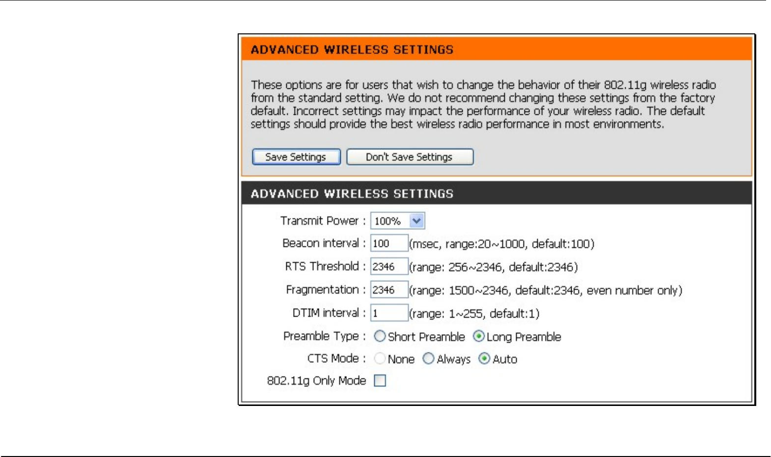
Advanced Wireless
The Advanced Wireless menu is used
to configure settings that can increase
the performance of your router. Click
Save Settings when you have
completed your changes.
See the table below for descriptions of
the advanced wireless settings
parameters.

Section 3 – Configuration
D-Link DIR-320 User Manual 53
Performance
Parameter Description
Transmit power Allows the user to adjust the transmit power of the router. A high transmit power allows a greater area range of accessibility to the router. When
multiple overlapping access points are present, it may be desirable to reduce transmission power.
Beacon Interval Beacons are emitted from the router in order to synchronize the wireless network. You may set the Beacon Interval range between 20-100
microseconds per beacon sent. The default is 100.
RTS Threshold The RTS (Request to Send) Threshold controls the size of data packets issued to a RTS packet. A lower level will send packets more frequently
which may consume a great amount of the available bandwidth. A high threshold will allow the router to recover from interference or collisions
which is more prevalent in a network with high traffic or high electromagnetic interference. The default setting is 2346.
Fragmentation The fragmentation threshold will determine if packets are to be fragmented. Packets over the 2346 byte limit will be fragmented before
transmission. 2346 is the default setting.
DTIM Period DTIM (Delivery Traffic Indication Message) Period is a countdown informing clients of the next menu for listening to broadcast and multicast
messages. The default setting is 1.
Preamble Type Long Preamble should be used where 802.11b clients are present.
CTS Mode Clear to Send mode should only be used when wireless clients are close enough to each other to “hear“ or detect the presence of ther other clients.
The Auto option will use CTS mode only when associating clients are in close proximity to each other.
802.11g Only Mode The access point can be forced to associate with exclusively 802.11g devices.
Fragmentation The fragmentation threshold will determine if packets are to be fragmented. Packets over the 2346 byte limit will be fragmented before
transmission. 2346 is the default setting.
Section 3 – Configuration
D-Link DIR-320 User Manual 54
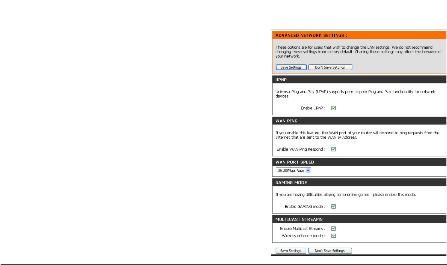
Advanced Network
The Advanced Network Settings menu is used to disable or enable UPnP, disable Ping responses on the WAN port and change WAN port speed.
UPnP
UPnP supports zero-configuration networking and automatic discovery for many types
of networked devices. When enabled, it allows other devices that support UPnP to
dynamically join a network, obtain an IP address, convey its capabilities, and learn
about the presence and capabilities of other devices. DHCP and DNS service can also
be used if available on the network. UPnP also allows supported devices to leave a
network automatically without adverse effects to the device or other devices on the
network.
Diverse networking media including Ethernet, 802.11b/g Wireless, Firmware, phone line
and power line networking can support UPnP. To enable UPnP, tick the Enable UPnP
checkbox.
WAN Ping
This feature allow users to either allow or block a Ping test from outside computers
looking to check the connectivity of your device. This is usually attempted by hackers
trying to access your router or computer from a remote device on the WAN side of the
connection. Tick the Enable WAN Ping Respond checkbox to allow WAN pinging of
your device.
WAN Port Speed
This section allows the user to set the wire speed over which the router will transmit
packets. The user has three options:
10Mbps – Selecting this option from the drop-down menu will set the wire speed
at 10 megabytes per second.
100Mbps – Selecting this option from the drop-down menu will set the wire
speed at 100 megabytes per second.
10/100 Mbps Auto – Selecting this option from the drop-down menu will allow
the wire speed to be automatically set by the Router depending on the wire
speed available at any given time.
Section 3 – Configuration
D-Link DIR-320 User Manual 55
Gaming Mode
When gaming mode is enabled, the router’s QoS settings are adjusted automatically to accommodate Internet gaming. Gaming mode is enabled by
default.
Multicast Streams
Wireless enhanced mode is used to optimize traffic parameters for wireless clients.
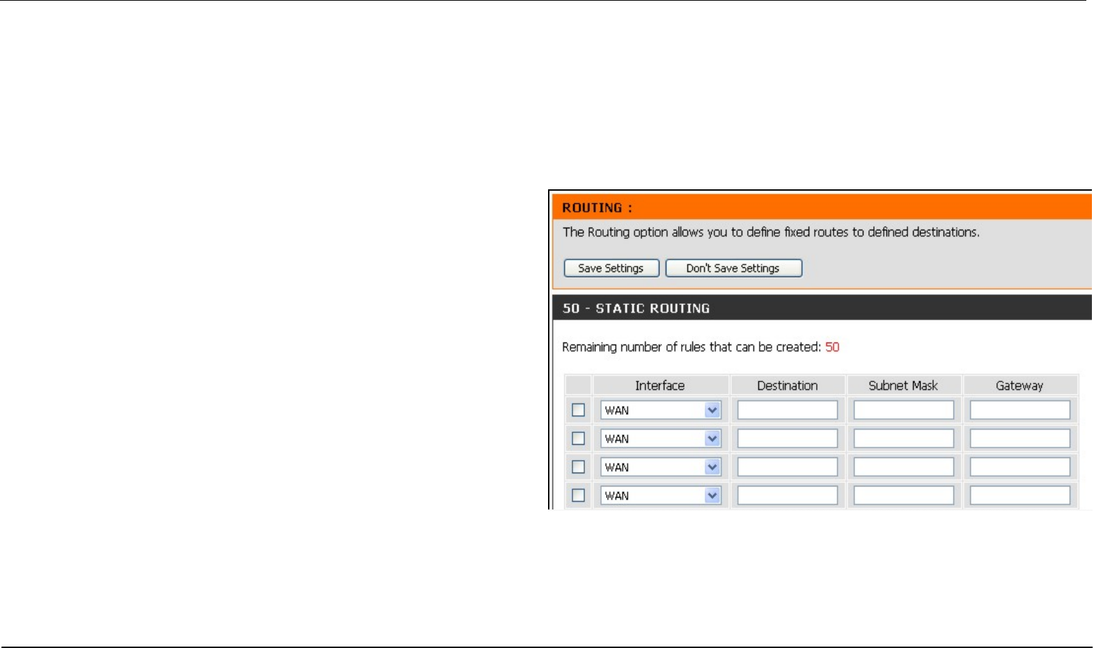
Routing
Use Static Routing to specify a route used for data traffic within your
Ethernet LAN or to route data on the WAN. This is used to specify that
all packets destined for a particular network or subnet use a
predetermined gateway. Static routing on the WAN is only supported if
your WAN connection protocol is not using PPPoE.
To add a static route to a specific destination IP address, choose the
Interface, enter a Destination IP address, select a suitable Subnet
Mask, and type in the Gateway IP address. Click the Save Settings
button at the top of the menu when you are finished.
Section 3 – Configuration
D-Link DIR-320 User Manual 56
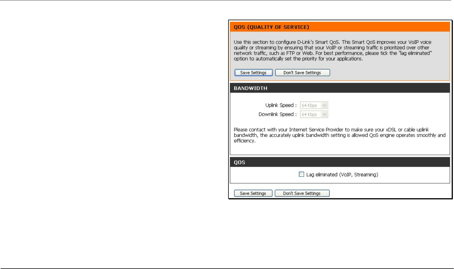
QoS Engine
Some broadband service providers allow subscribers to adjust Quality of
Service (QoS) settings to optimize the Internet connection for VoIP and
other time sensitive network applications. If your ISP allows this, enable
QoS bandwidth adjustment by clicking to select the Lag eliminated box
and adjust the Uplink and Downlink speed using the pull-down menus.
Click the Save Settings button to implement the new QoS changes.
Section 3 – Configuration
D-Link DIR-320 User Manual 57
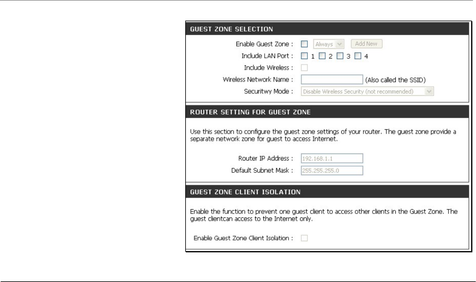
Guest Zone
The Guest Zone feature of the router allows an
additional subnet to be added. This is especially useful
for placing wireless stations in an IP subnet separate
from wired Ethernet stations. The four Ethernet ports
can also be configured to use the Guest Zone so one
or more Ethernet ports can be on a separate IP subnet.
To use a guest zone, click to select the Enable Guest
Zone box, if desired select a schedule when the Guest
Zone is effective. To create a new schedule, click the
Add New button to go to the Schedules menu.
The Guest Zone can be applied to any Ethernet port by
selecting it from the Include LAN Port menu.
To create a new wireless SSID for the Guest Zone,
check to select the Include Wireless box, then
configure the new Wireless Network Name (SSID) and
the security used for the new SSID.
The default IP subnet for the guest zone is
192.168.1.0. To change the IP address scheme for the
guest zone type the new Router IP Address and
Subnet Mask in space provided.
If the Enable Guest Zone Client Isolation option is
selected, the router will not exchange traffic between
clients on the guest zone’s newly created subnet.
Guest zone client will be able to access the Internet
only.
Click the Save Settings button to implement the
changes.
Guest Zone menu (upper portion)
Section 3 – Configuration
D-Link DIR-320 User Manual 58
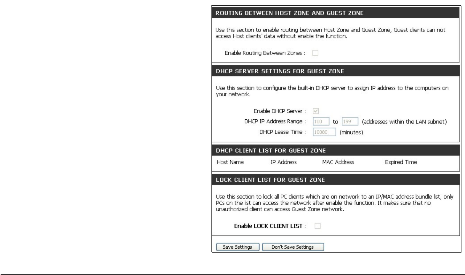
Routing between the guest zone and the original host
subnet can be enabled by clicking the Enable Routing
Between Zones box. If this option is not selected, the
two subnets will behave as separate networks with
access to the Internet connection, but not to computers
on the other subnet.
The DHCP server for the guest zone is configured
exactly the same as the DHCP server to the original
host zone. DHCP clients on the guest zone are listed
below the DHCP server setup menu.
The Enable Lock Client List option will create static
IP addresses for all current DHCP clients and leasers.
When this is enabled, no more DHCP clients are
allowed, the list is locked.
Click the Save Settings button to implement the
changes.
Guesst Zone menu (lower portion)
Section 3 – Configuration
D-Link DIR-320 User Manual 59
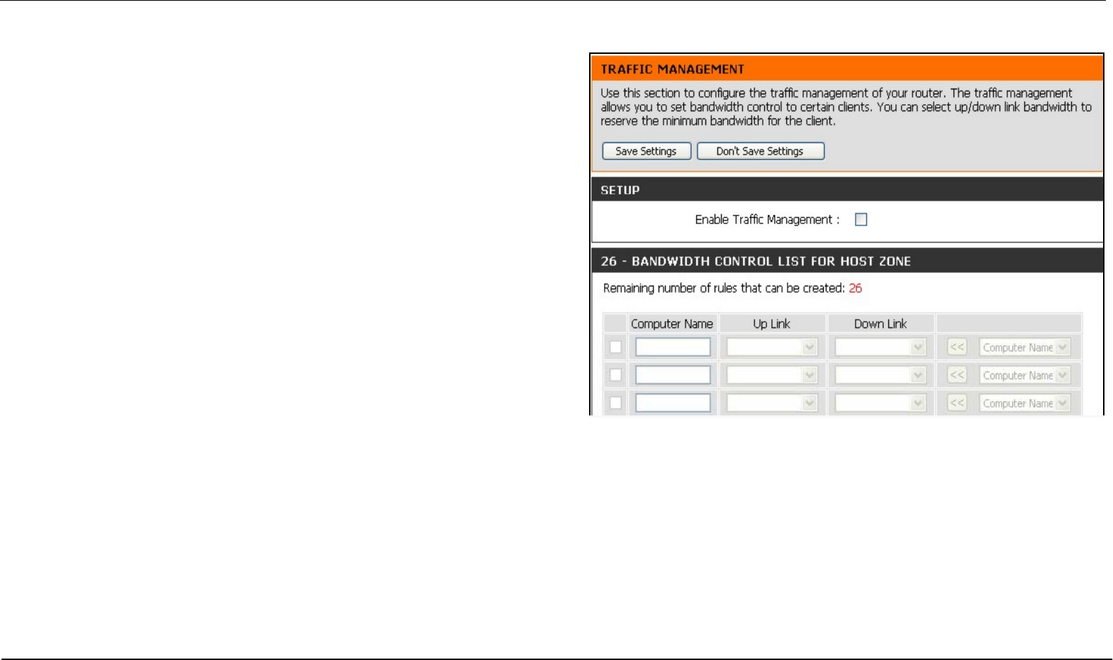
Traffic Management
The Traffic Management is used to control Internet connection
bandwidth for individual computers on the wired or wireless network. Up
to 26 clients can be added to the list for bandwidth control.
Section 3 – Configuration
D-Link DIR-320 User Manual 60
Maintenance
The menus of the Maintenance directory include Device Administration, Save and Restore, Firmware Update, DDNS Setting, System Clock,
Schedules and Log Settings.
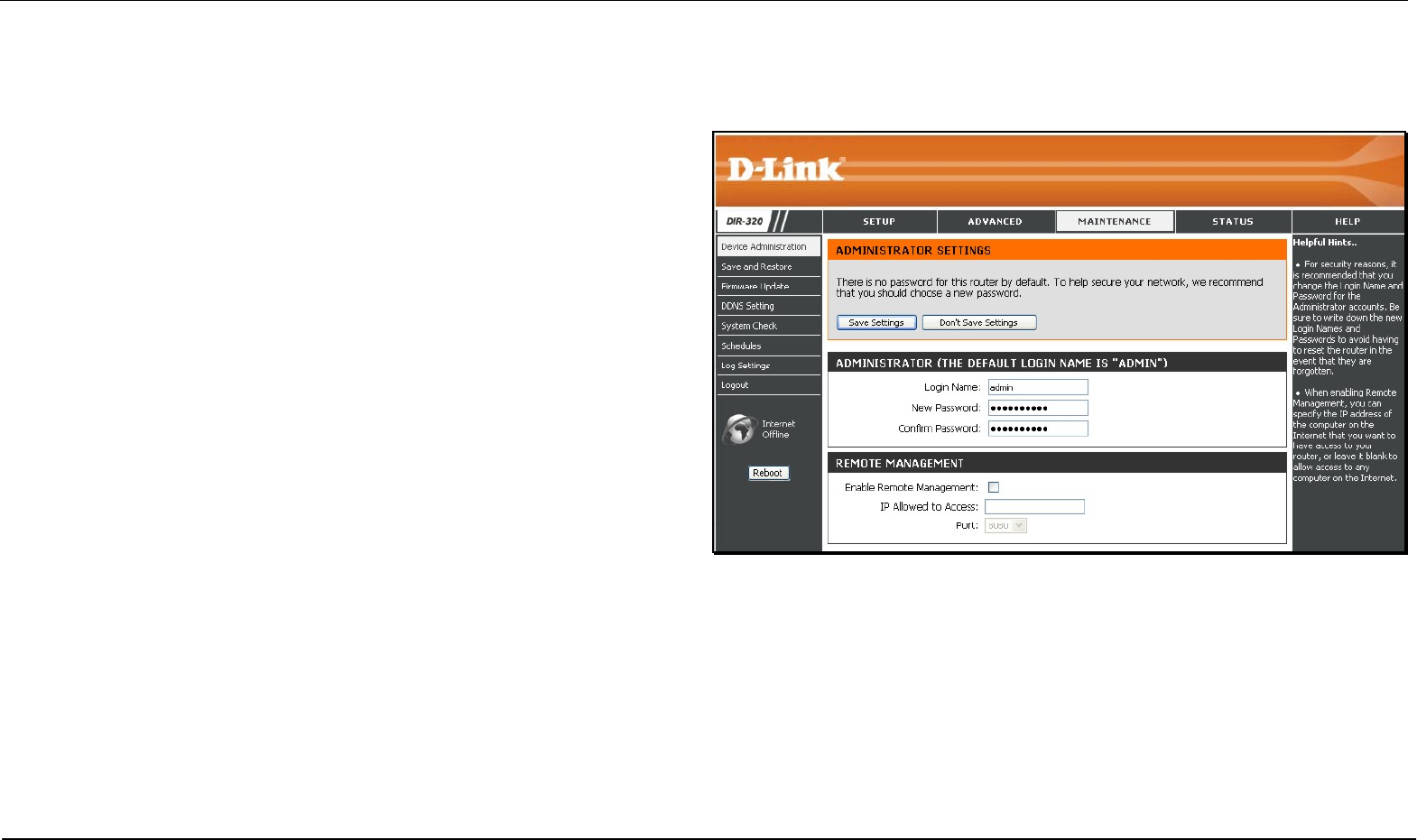
Device Administration
The Device Administrator menu is used to change the administrator’s
login name and password as well as remote management set up. To
change the login name or password, enter the new Login Name and
password into the New Password field and repeat the password in the
Confirm Password field. Click Save Settings to set your new
password.
This window will also allow the user to enable remote management of
the device from a remote computer. To configure this function, click
Enable Remote Management under the Remote Management
heading and type IP address of the system used for remote
management. Click Save Settings to set these configurations into the
memory of the Router.
Section 3 – Configuration
D-Link DIR-320 User Manual 61
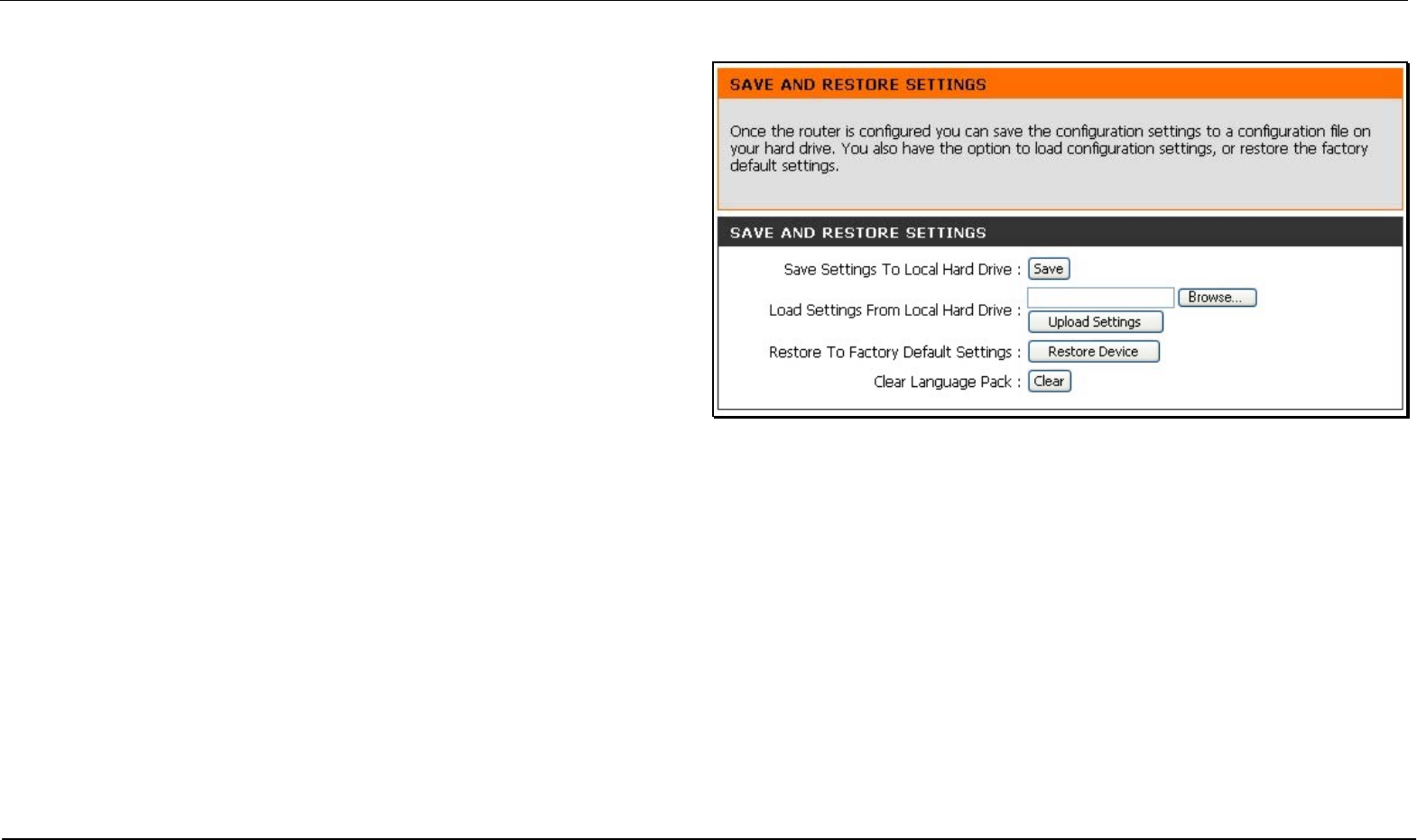
Save and Restore
Current system settings can be saved as a file onto the local hard drive
by clicking the Save button. The saved file or any other saved setting file
can be loaded back on the Router. To reload a system settings file, click
on Browse to browse the local hard drive and locate the system file to
be used. You may also reset the Router back to factory settings by
clicking on Restore Device.
Section 3 – Configuration
D-Link DIR-320 User Manual 62
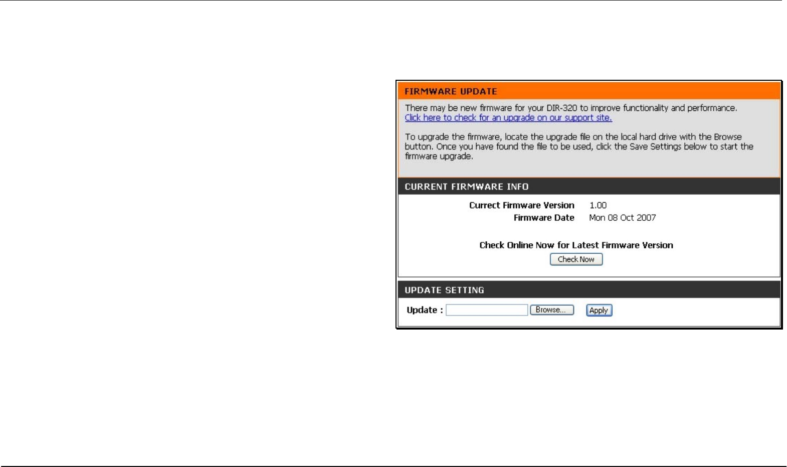
Firmware Update
View the version of the currently loaded firmware and update the system firmware with the Firmware Update menu. Make sure the firmware you
want to use is on the local hard drive of the computer. Click on Browse to browse the local hard driver and locate the firmware to be used for the
update. Please check the D-Link support site for firmware updates at D-Link Technical support website of your country.
In order to keep pace with changes in standards and technology, the
DIR-320 allows you to easily update the embedded firmware. You may
obtain the latest version of the DIR-320 firmware by logging onto the
D-Link web site at www.dlink.com. If you are connected to the Internet,
you can access the D-Link web site by clicking on Check Now. The
Firmware Upgrade window lists the version of the firmware the Router is
currently using. If you would like to update, follow the instructions given
on the D-Link web site firmware update page to download the new
firmware. You can then use the DIR-320 Firmware Upgrade Utility
included with the Router to transfer the new firmware to the Router. Once
you have downloaded the new firmware to your computer, use the
Browse button to find where it is located on your computer, or if you
know the path of the file, enter it into the space provided. Click Apply to
begin the download. After the new firmware has been successfully
downloaded into your Router, restart the device to let the changes take
effect.
Section 3 – Configuration
D-Link DIR-320 User Manual 63
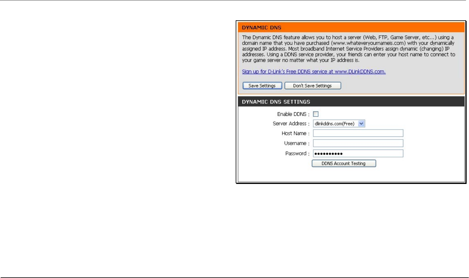
DDNS Setting
The DIR-320 supports DDNS or Dynamic Domain Name Service.
Dynamic DNS allows a dynamic public IP address to be associated with
a static host name in any of the many domains, allowing access to a
specific host from various locations on the Internet. With this function
enabled, remote access to a host will be allowed by clicking a URL
hyperlink in the following form: dlinkddns.com Because many ISPs
assign public IP addresses using DHCP, it can be difficult to locate a
specific host on the LAN using the standard DNS. For example, if you
are running a public web server or VPN server on your LAN, DDNS
ensures that the host can be located from the Internet if the public IP
address changes. DDNS requires that an account be set up with one of
the supported DDNS servers.
To implement Dynamic DNS, first tick the Enable DDNS checkbox in the
window above, then choose the Server Address from the list in the
pull-down menu. Next, enter the Host Name of the LAN to be accessed,
and the Username and Password for the DDNS account. Click the
Save Settings button to save changes made. Use the DDNS Account
Testing button to make sure the DDNS service is functioning.
Section 3 – Configuration
D-Link DIR-320 User Manual 64
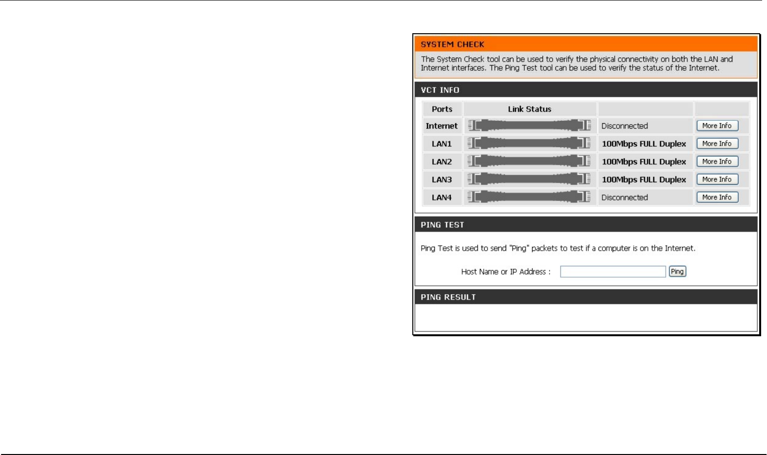
System Check
This menu is used to monitor port performance and connectivity, the menus
displayed are VCT Info and Ping Test.
VCT Info
The Virtual Cable Tester displays the current status of all ports.
Ping Test
The Ping Test section allows you to ping any IP address from the Router to
test connectivity to the address. To Ping a device, enter the IP address of the
device that you wish to ping into the Host Name or IP Address field and click
Ping to start the Ping mechanism. The results of the Ping will be shown under
the Ping Result heading.
Section 3 – Configuration
D-Link DIR-320 User Manual 65
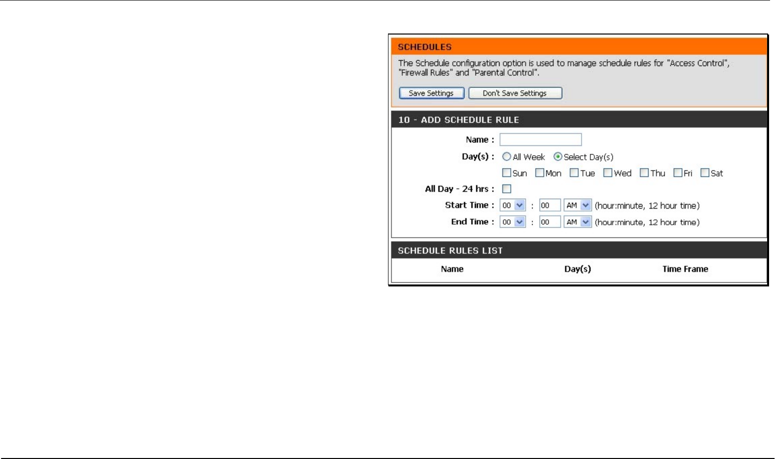
Schedules
This window is used to create implementation schedules. This is the
same menu accessed using the Make New Schedule button in the
rules menu of various settings pages.
Schedule rule setup menu
Complete the Add Schedule Rule settings on the window above and
then click the Save Settings button at the top of the window.
Section 3 – Configuration
D-Link DIR-320 User Manual 66
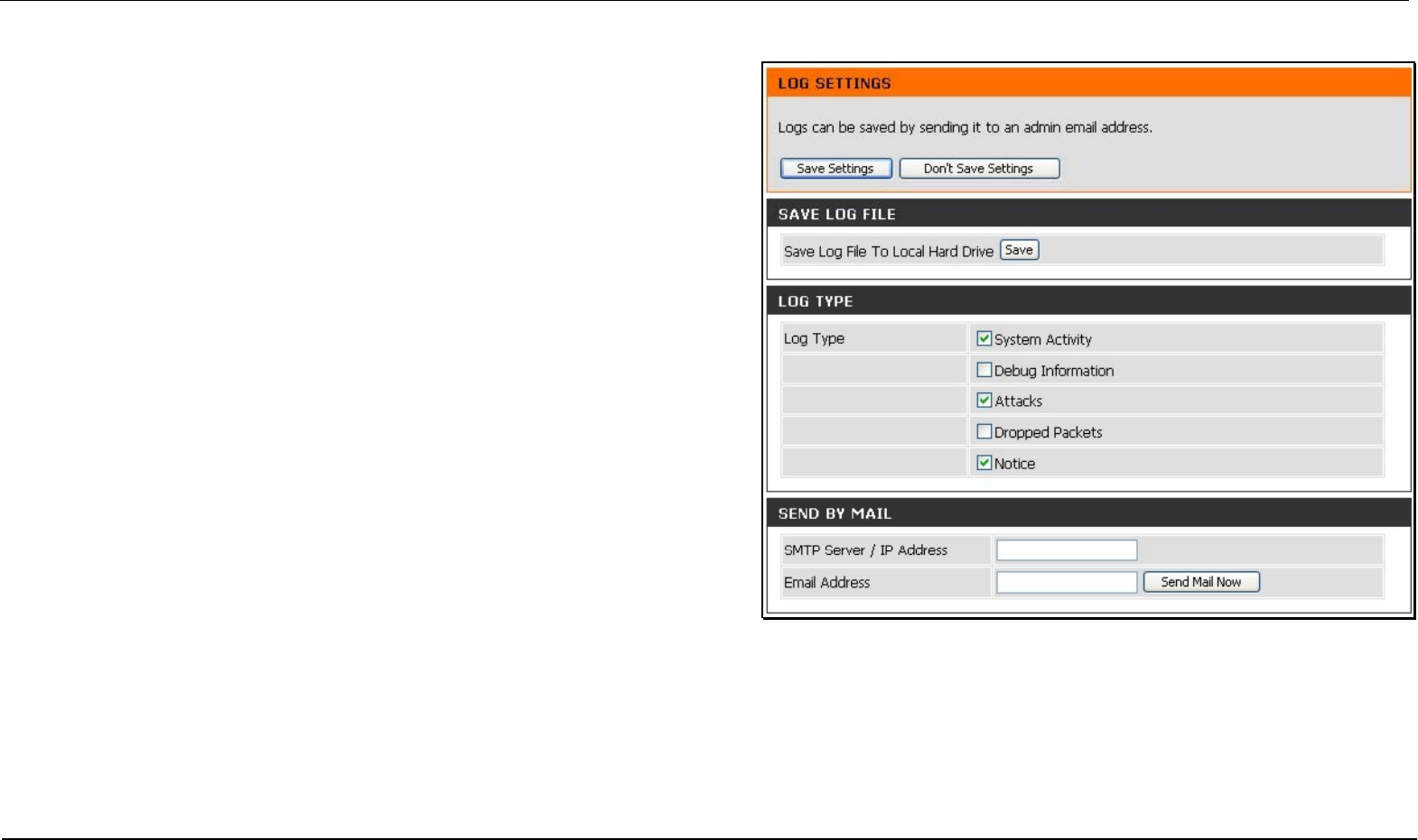
Log Settings
The system log displays chronological event log data, including System
Activity, Debug Information, Attacks, Dropped Packets, and Notice. Check the
desired category of Log Type in the bottom half of the window above and then
click the Save button and follow the prompts to save the file.
Alerts can be sent to an email account. Use the Send By Mail settings to
configure Email account information. Click the Send Me Now button to email
alerts to a previously configured email account.
Section 3 – Configuration
D-Link DIR-320 User Manual 67
Status
The Status directory menus are used to check information about the Router, including Device Information, Log, Statistics, and Active Session.
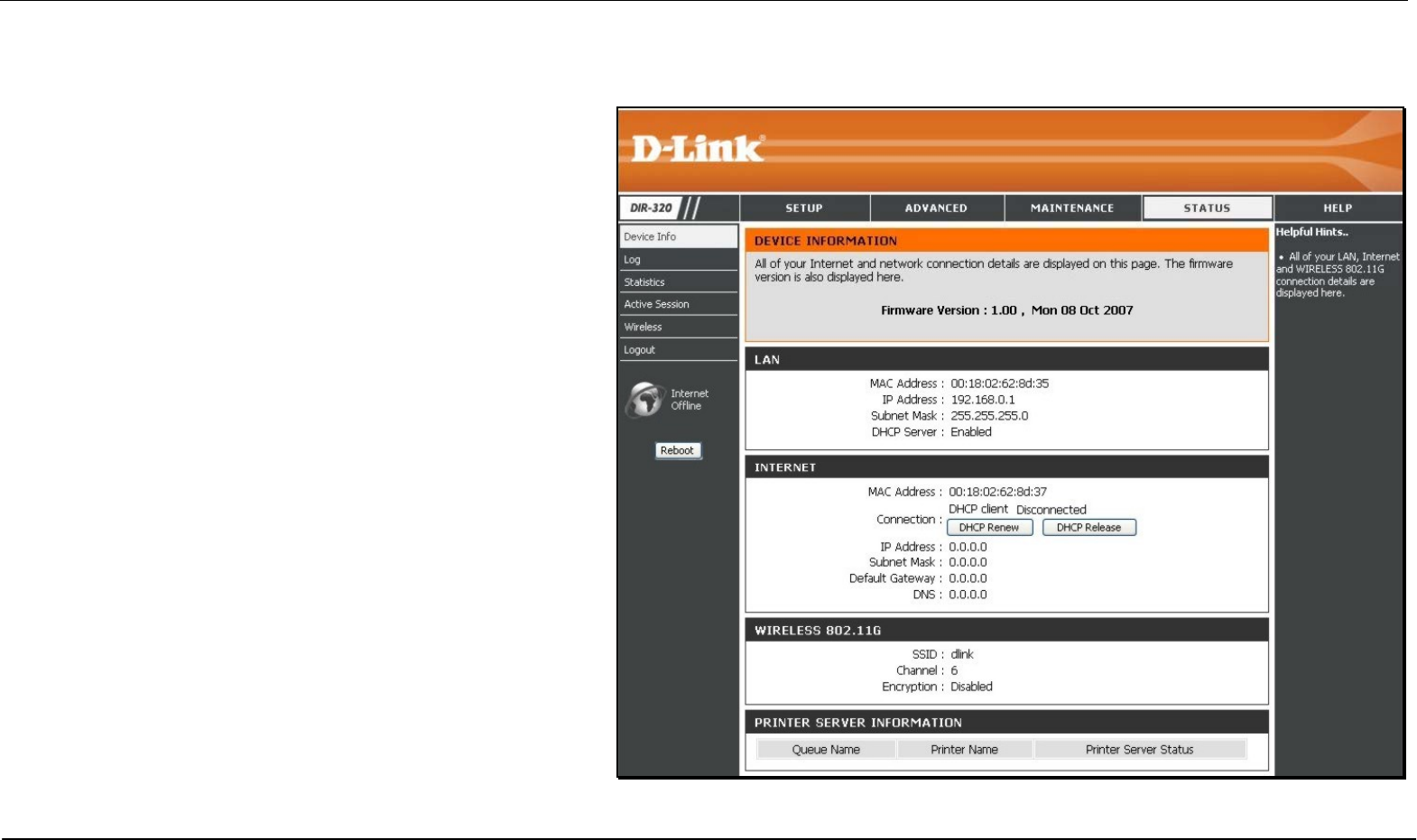
Device Information
The Device Information display is used to view information
regarding the settings of the Router, both on the LAN side and
WAN side of the connection. The firmware version is also
displayed here as well as in the firmware upgrade menu.
Section 3 – Configuration
D-Link DIR-320 User Manual 68
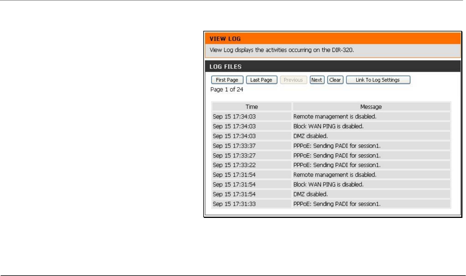
Log
The Log displays events occurring within the router by time
and date, and also view the source and destination of the
event. The user may use the First Page, Last Page,
Previous and Next buttons to scroll through the log events
listed in the window. To clear the log events, click Clear.
Click the Link to Log Settings button to change what events
are displayed in the log.
Section 3 – Configuration
D-Link DIR-320 User Manual 69
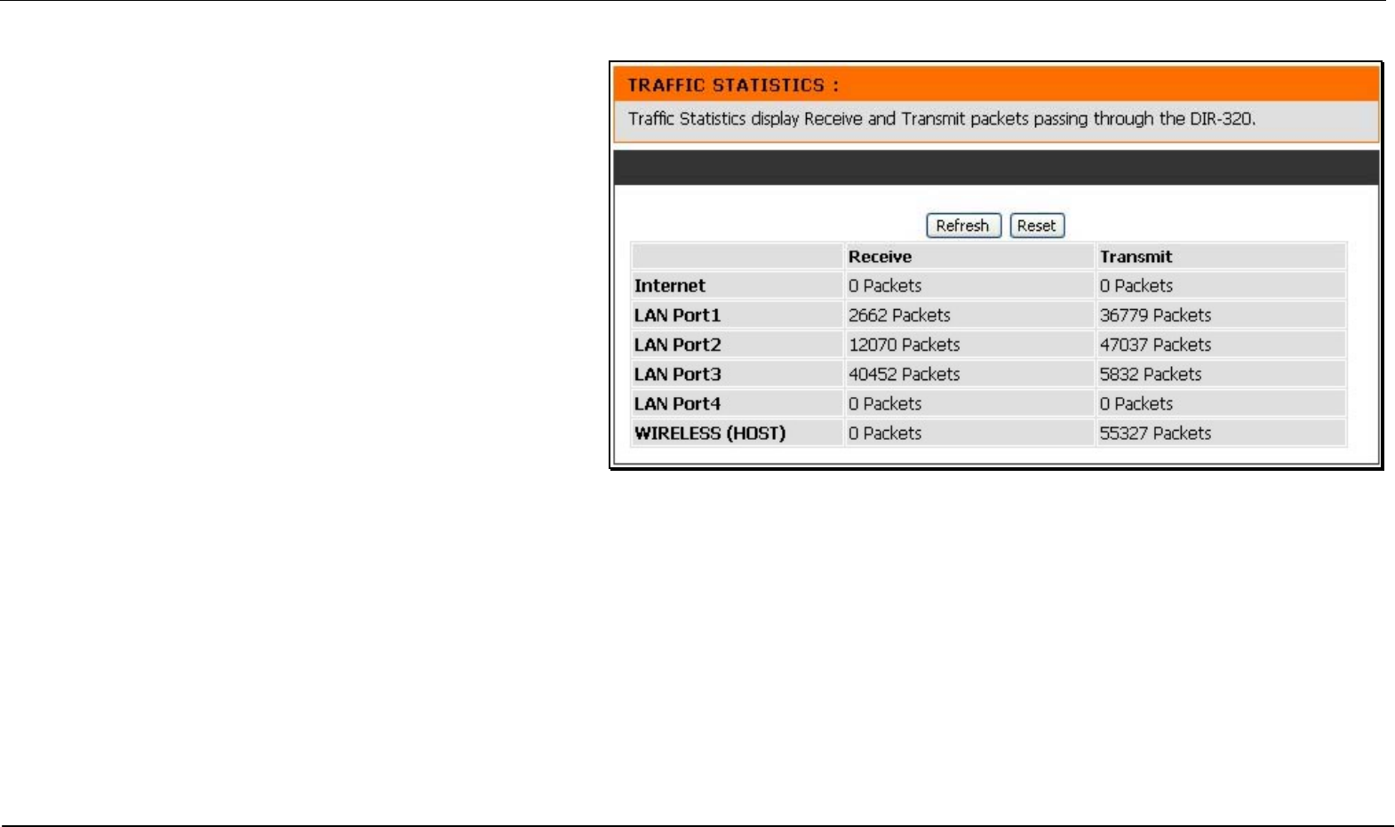
Statistics
The Statistics displays shows transmitted and received
packets occurring on the Router. To refresh the window, click
Refresh. To restart the packet count, click Reset.
Section 3 – Configuration
D-Link DIR-320 User Manual 70
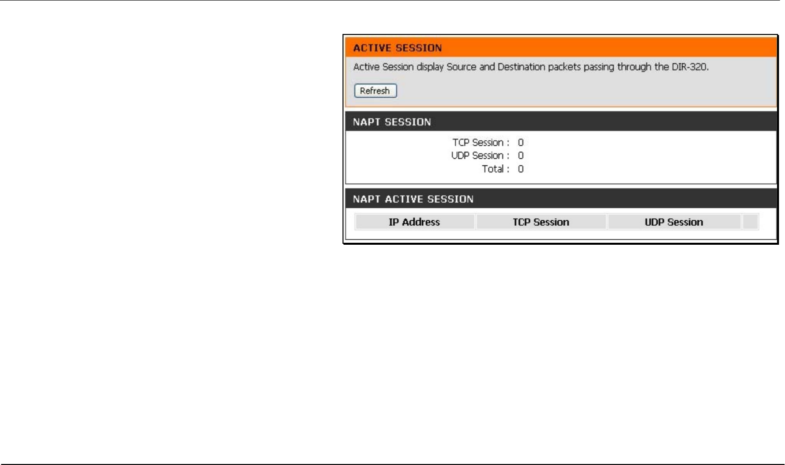
Active Session
Source and Destination packets passing through the Router
are displayed listed by TCP/UDP type in the Active Session
display. To refresh the window, click the Refresh button.
Section 3 – Configuration
D-Link DIR-320 User Manual 71
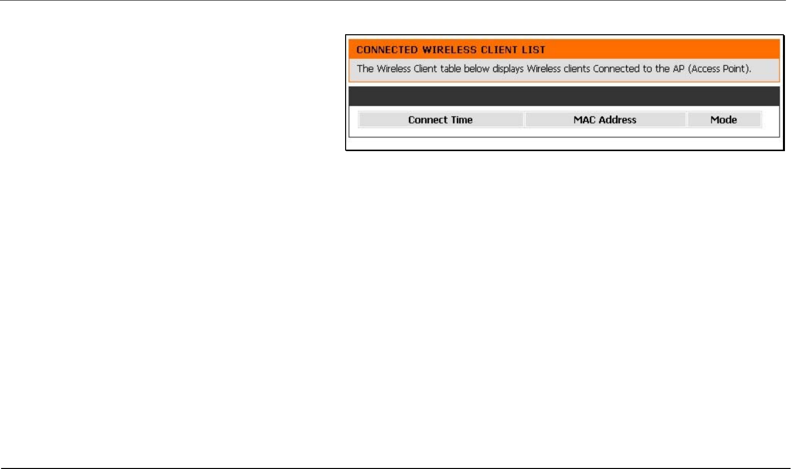
Wireless Client List
The Connected Wireless Client List displays all wireless
clients currently connected and the mode of the connection.

Appendix – Technical Specifications
D-Link DIR-320 User Manual 72
Technical Specifications
Standards
• IEEE 802.11g
• IEEE 802.11b
• IEEE 802.3
• IEEE 802.3u
Wireless Signal Rates*
• 54 Mbps • 48 Mbps
• 36 Mbps • 24 Mbps
• 18 Mbps • 12 Mbps
• 11 Mbps • 9 Mbps
• 6 Mbps • 5.5
• 2 Mbps • 1 Mbps
Security
• WPA - Wi-Fi Protected Access (TKIP, MIC, IV Expansion,
Shared Key Authentication)
• 802 .1x
• 64/128-bit WEP
* Maximum wireless signal rate derived from IEEE Standard 802.11g specifications. Actual data
throughput will vary. Network conditions and environmental factors, including volume of network traffic,
building materials and construction, and network overhead, lower actual data throughput rate.
Environmental factors will adversely affect wireless signal range.
Modulation Technology
802.11g 802.11b
• BPSK • DQPSK
• QPSK • DBPSK
• 16QAM • DSSS
• 64QAM • CCK
• OFDM
Wireless Frequency Range
2412 ~ 2462 MHz ISM band
Wireless Operating Range
• Indoors - up to 328 ft. (100 meters)
• Outdoors- up to 1312 ft. (400 meters)
External Antenna Type
Single detachable reverse SMA

Appendix – Technical Specifications
D-Link DIR-320 User Manual 73
VPN Pass Through/ Multi-Sessions
• PPTP
• L TP
• IPSec
Device Management
• Web-based Internet Explorer v6 or later; Netscape
• Navigator v6 or later; or other Java-enabled browsers
• DHCP Server and Client
Advanced Firewall Features
• NAT with VPN Pass-through (Network Address Translation)
• MAC Filtering
• IP Filtering
• URL Filtering
• Domain Blocking
• Scheduling
Input: DC 5V 2A
Operating Temperature
32°F to 131°F ( 0°C to 55°C)

Appendix – Technical Specifications
D-Link DIR-320 User Manual 74
Humidity
95% maximum (non-condensing)
Safety and Emissions
FCC
LEDs
• Power
• Status
• Internet
• WLAN (Wireless Connection)
• LAN (10/100)
• USB
Dimensions
L = 5.6 (142mm)
W = 4.3 (109mm)
H = 1.2 inches (31mm)
Weight
7.8 oz (0.22kg)
Warranty
1 Year

Appendix – Technical Specifications
D-Link DIR-320 User Manual 75
Web-based management function navigator
SETUP ADVANCED MAINTENANCE STATUS HELP
Internet Setup
Port Forwarding
Device
Administration Device Info Menu
Wireless Setup
Application
Rules Save and Restore Logs Logout
LAN Setup Access Control Firmware Update Statistics
Printer Setup Firewall & DMZ
DDNS Setting Active Session
Time and Date
Advanced
Wireless System Check LAN Clients
Parental
Control Advanced
Network Schedules Logout
Logout Routing Log Settings
QoS Engine Logout
Guest Zone
Traffic
management
Logout

Appendix – Technical Specifications
D-Link DIR-320 User Manual 76
FCC Warning statement:
This equipment has been tested and found to comply with the limits for a Class B digital device, pursuant to part 15 of the FCC rules. These limits are designed to provide
reasonable protection against harmful interference in a residential installation. This equipment generates, uses and can radiate radio frequency energy and, if not installed
and used in accordance with the instructions, may cause harmful interference to radio communications. However, there is no guarantee that interference will not occur in a
particular installation. If this equipment does cause harmful interference to radio or television reception, which can be determined by turning the equipment off and on, the
user is encouraged to try to correct the interference by one or more of the following measures:
-Reorient or relocate the receiving antenna.
-Increase the separation between the equipment and receiver.
-Connect the equipment into an outlet on a circuit different from that to which the receiver is connected.
-Consult the dealer or an experienced radio/TV technician for help.
1. This Transmitter must not be co-located or operating in conjunction with any other antenna or transmitter.
2. This equipment complies with FCC RF radiation exposure limits set forth for an uncontrolled environment. This equipment should be installed and
operated with a minimum distance of 20 centimeters between the radiator and your body.
3. Any changes or modifications (including the antennas) made to this device that are not expressly approved by the manufacturer may void the user’s
authority to operate the equipment.
交通部電信總局
低功率電波輻射性電機管理辦法 (930322)
根據交通部 低功率管理辦法 規定:
第十二條 經型式認證合格之低功率射頻電機,非經許可,公司、商號或使用者均不得擅自變更頻率、加大功率或變更原設計之特性及功能。
第十四條 低功率射頻電機之使用不得影響飛航安全及干擾合法通信;經發現有干擾現象時,應立即停用,並改善至無干擾時方得繼續使用。前項合法通信,指依電信法規定作業
之無線電通信。低功率射頻電機須忍受合法通信或工業、科學及醫療用電波輻射性電機設備之干擾。