D Link DIR410A1 M2M 3G VPN Router User Manual
D Link Corporation M2M 3G VPN Router
UserManual.wiki
>
D Link
>
DIR410A1 User Manual
User Manual
Navigation menu
Upload a User Manual
Namespaces
Wiki Guide
HTML
PDF
Info
Views
User Manual
Discussion / Help
Navigation
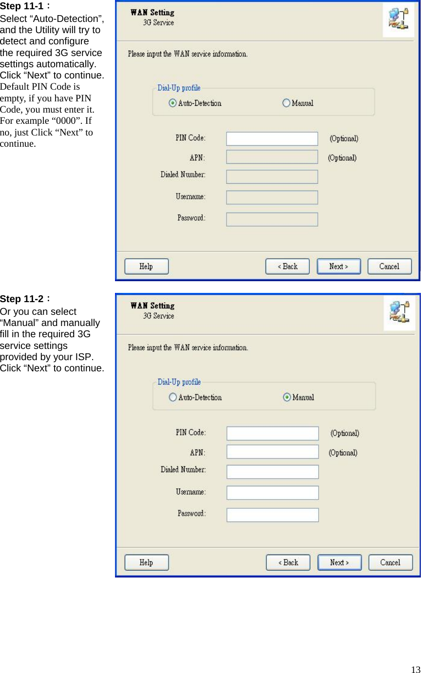
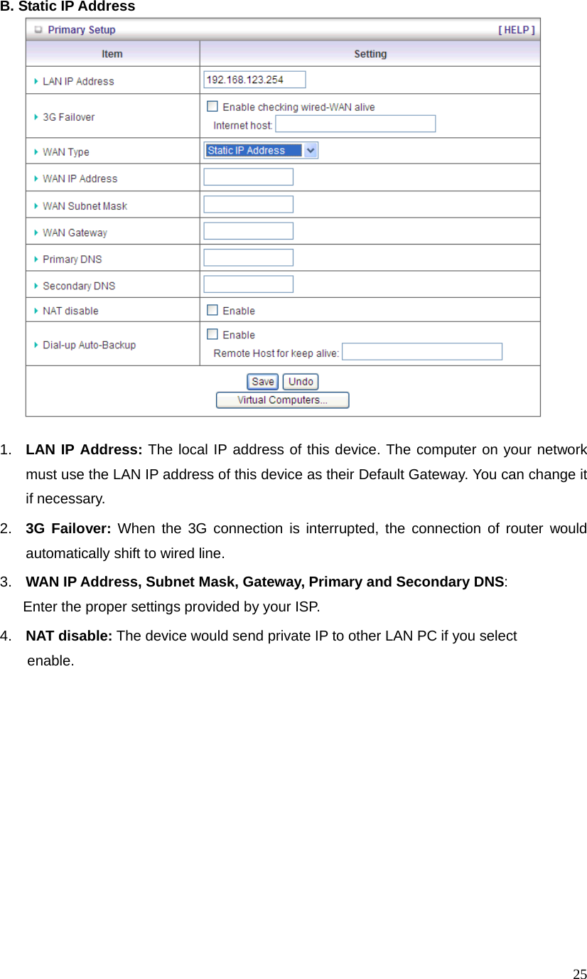
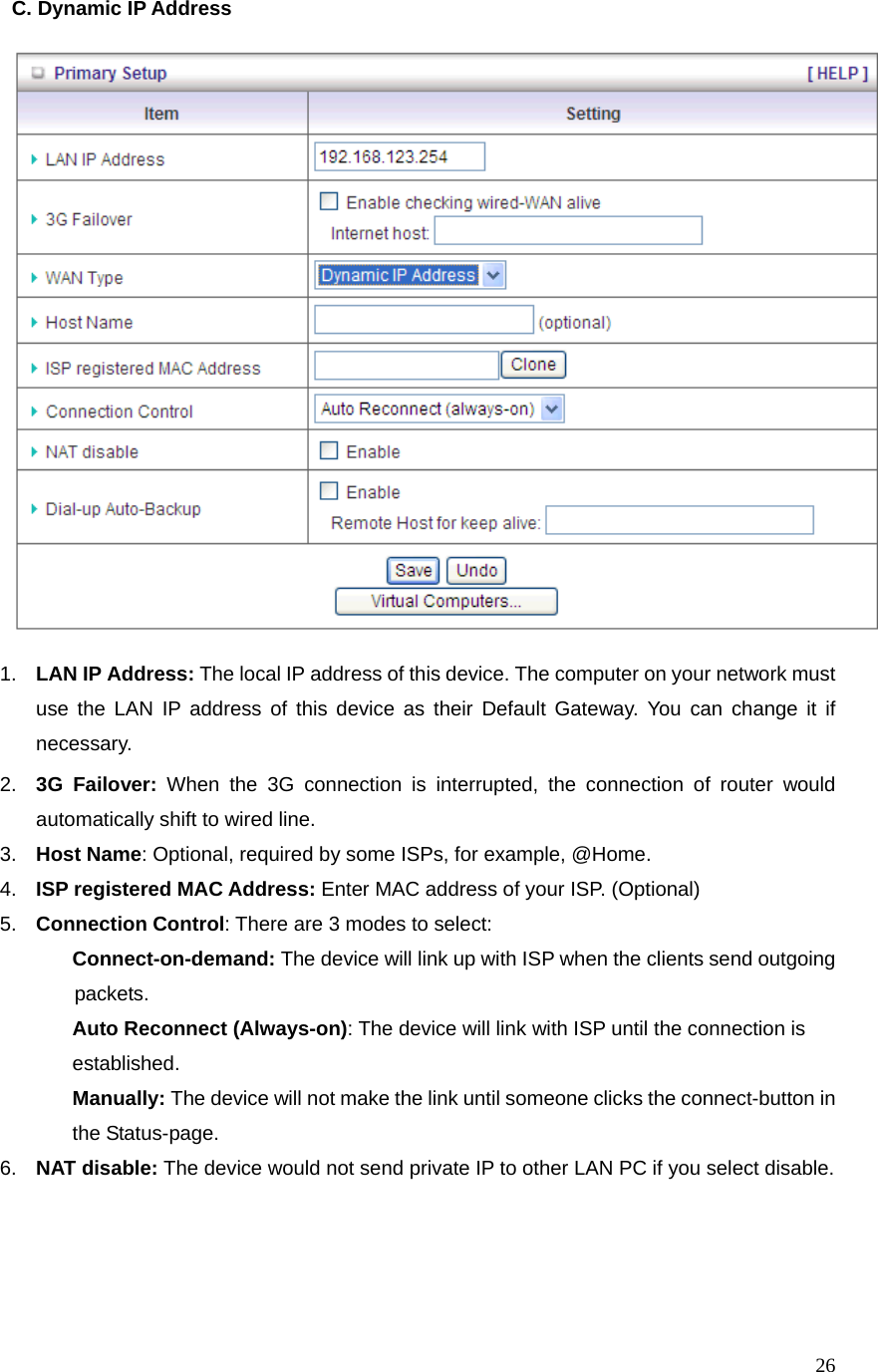
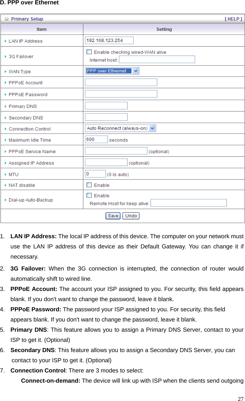
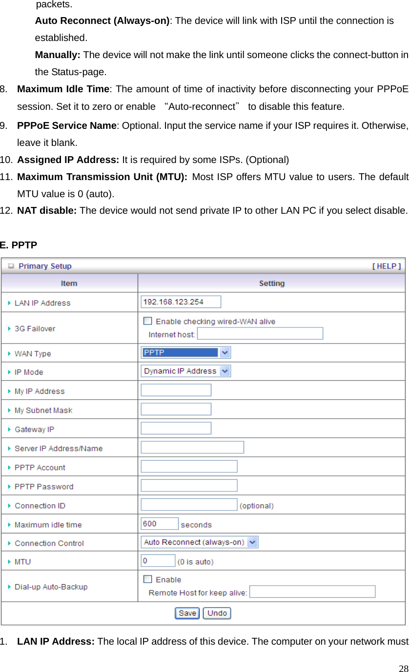
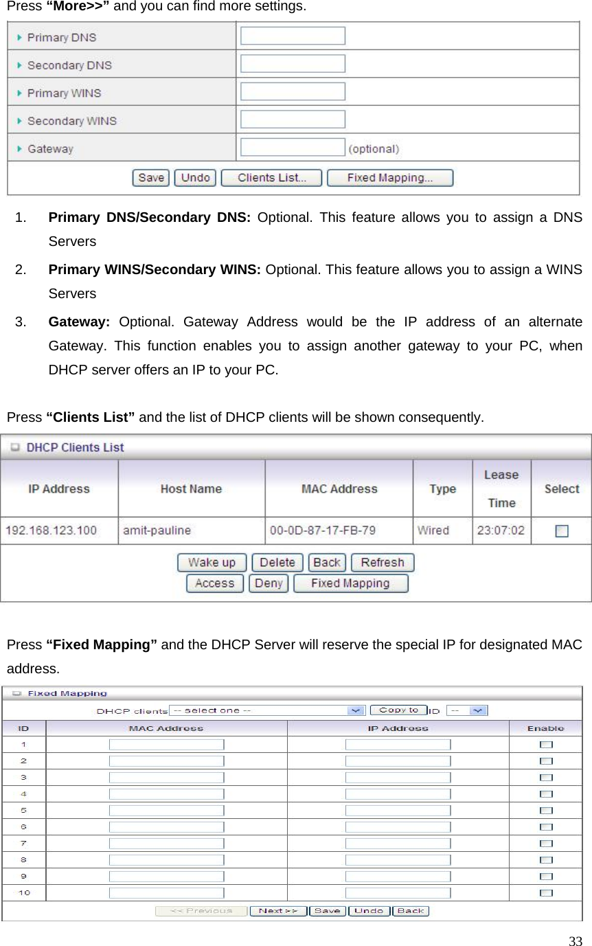
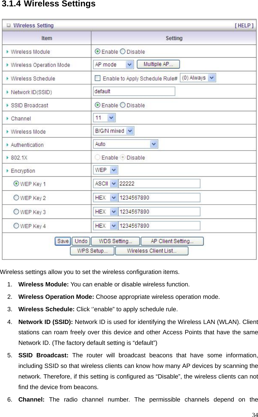
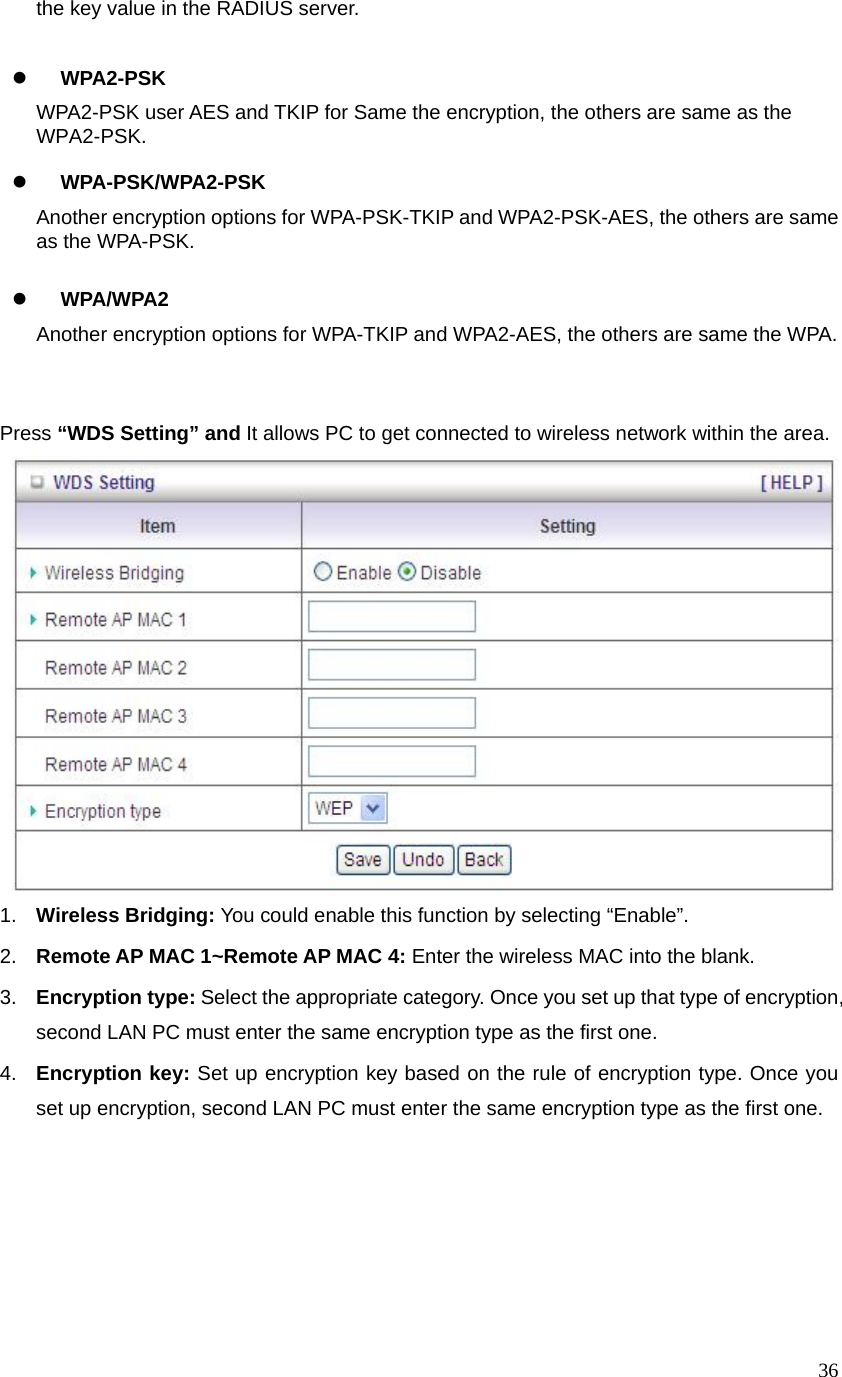
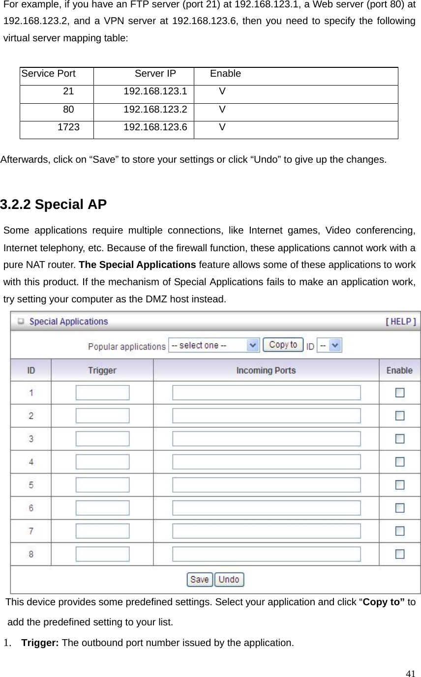
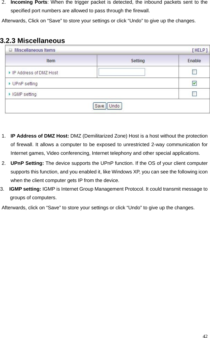
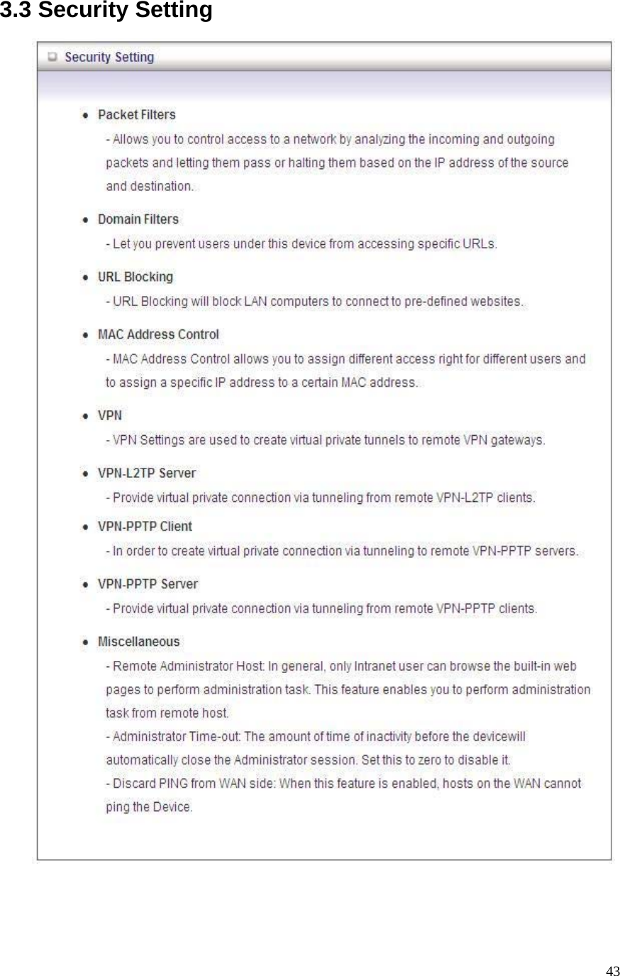
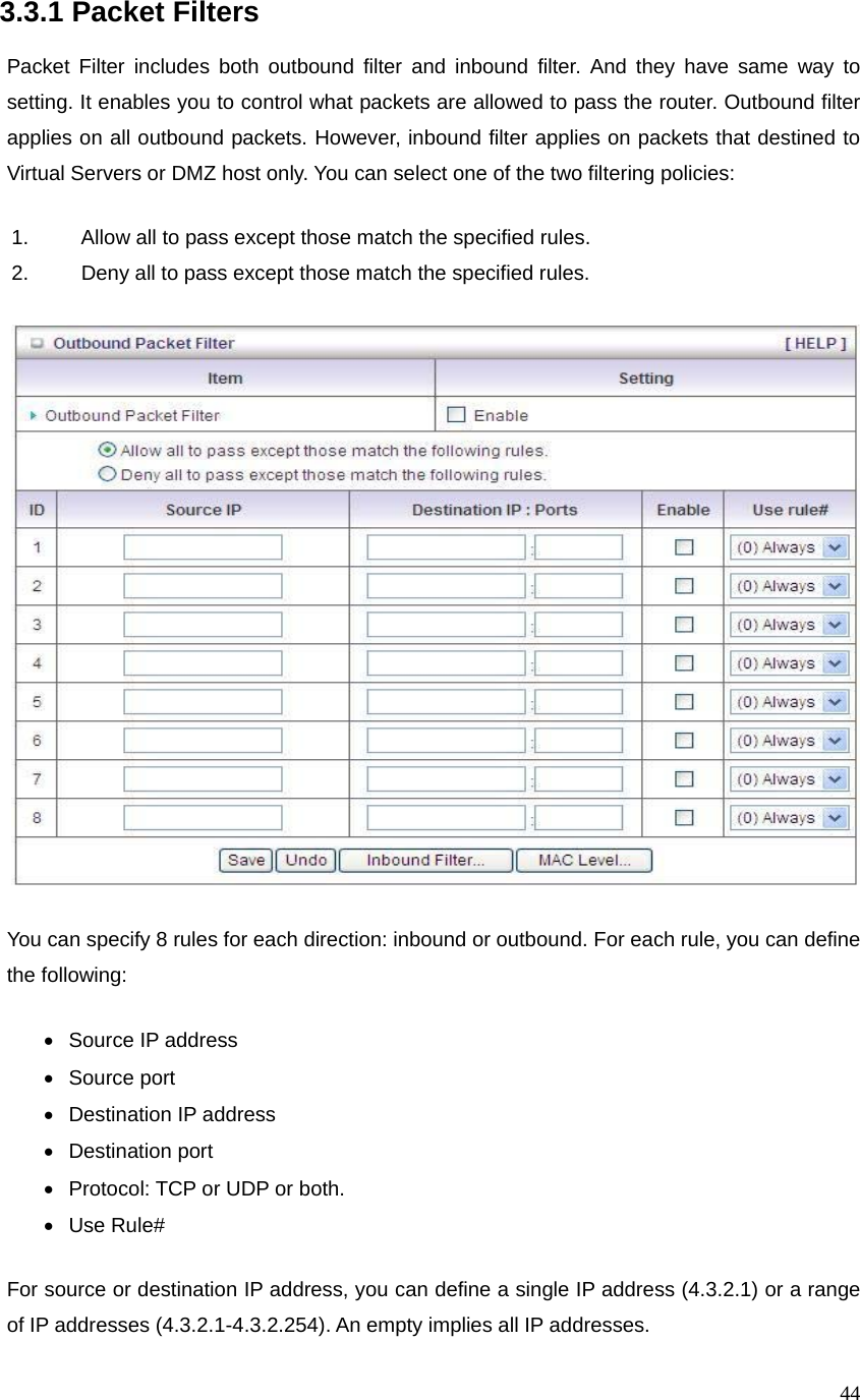
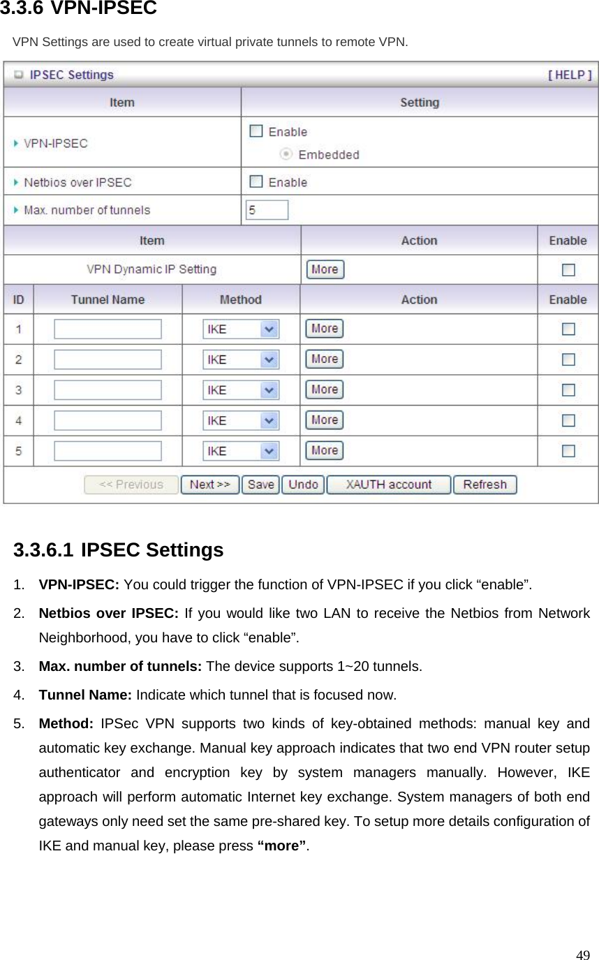
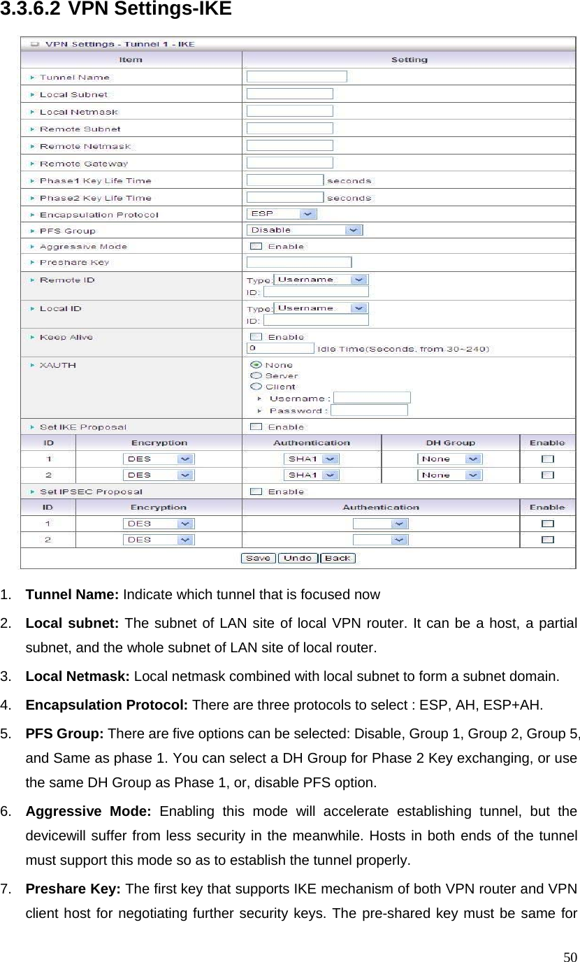
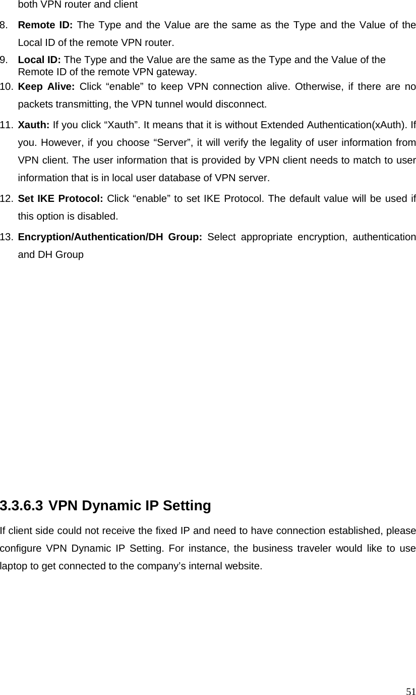
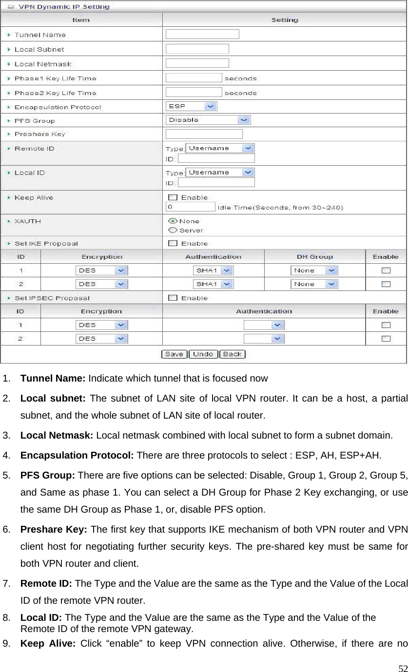
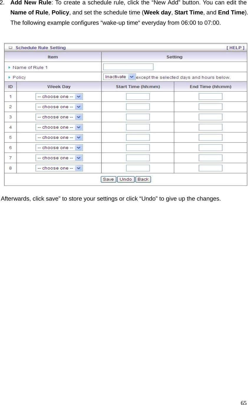
![12Step 9: Auto detect the WAN service, just click the [Next] button. Or you could select the WAN type by yourself via select the check box [Let me select WAN service by myself] Æ jump to Step 10. Step 10: Select the WAN type by yourself. You can get this information by asking your ISP.](https://usermanual.wiki/D-Link/DIR410A1/User-Guide-1420625-Page-12.png)