D Link DSL-2750U ADSL2+ 4-port Wireless Router User Manual User Mannul
D Link Corporation ADSL2+ 4-port Wireless Router User Mannul
UserManual.wiki
>
D Link
>
DSL 2750U User Manual
user manual
Navigation menu
Upload a User Manual
Namespaces
Wiki Guide
HTML
PDF
Info
Views
User Manual
Discussion / Help
Navigation
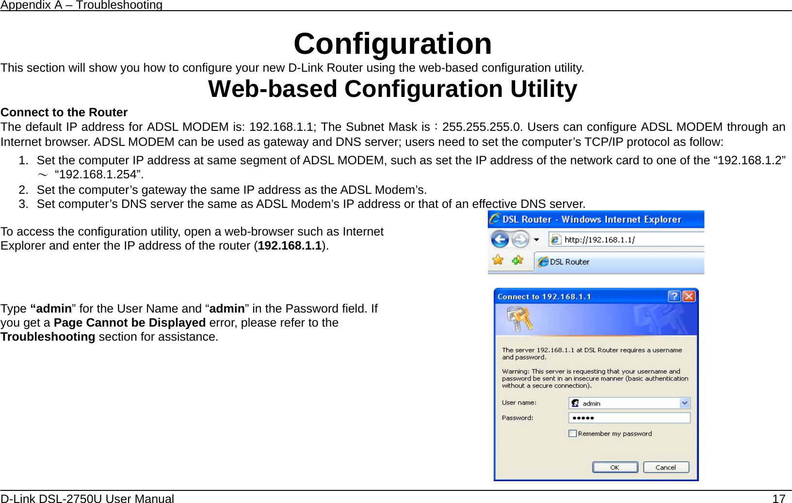


![Appendix A – Troubleshooting D-Link DSL-2750U User Manual 52 Enter the information in the section. Explanations of parameters are described below. Click the Apply / Save button to add the entry in the Active Outbound IP Filtering table. Filters Parameter Description Filter Name Enter a name for the new filter. IP Version Ipv4/Ipv6 Protocol Select the transport protocol (Any, TCP/UDP, TCP, UDP or ICMP) that will be used for the filter rule. Source IP address[/prefix length] Enter the start IP address which you are creating the filter rule. Source Port (port or port:port) The Source Port is the TCP/UDP port on either the LAN or WAN depending on if you are configuring an Outbound or Inbound Filter rule. Destination IP address[/prefix length] Enter the end IP address which you are creating the filter rule. Destination Port (port or port:port) The Destination Port is the TCP/UDP port on either the LAN or WAN depending on if you are configuring an Outbound or Inbound Filter rule.](https://usermanual.wiki/D-Link/DSL-2750U/User-Guide-1428293-Page-52.png)
![Appendix A – Troubleshooting D-Link DSL-2750U User Manual 54 Enter the information in the section. Explanations of parameters are described below. Click the Apply / Save button to add the entry in the Active Inbound IP Filtering table. Filters Parameter Description Filter Name Enter a name for the new filter. IP Version Ipv4/Ipv6 Protocol Select the transport protocol (Any, TCP/UDP, TCP, UDP or ICMP) that will be used for the filter rule. Source IP address[/prefix length] Enter the start IP address which you are creating the filter rule. Source Port (port or port:port) The Source Port is the TCP/UDP port on either the LAN or WAN depending on if you are configuring an Outbound or Inbound Filter rule. Destination IP address[/prefix length] Enter the end IP address which you are creating the filter rule. Destination Port The Destination Port is the TCP/UDP port on either the LAN or WAN depending on if you are configuring an Outbound or](https://usermanual.wiki/D-Link/DSL-2750U/User-Guide-1428293-Page-54.png)