D Link DWL3200APA1 IEEE 802.11g Wireless Access Point User Manual Antenna warning 20050128
D Link Corporation IEEE 802.11g Wireless Access Point Antenna warning 20050128
D Link >
Contents
installation guide part 2

Pole mountin
g
th d 2
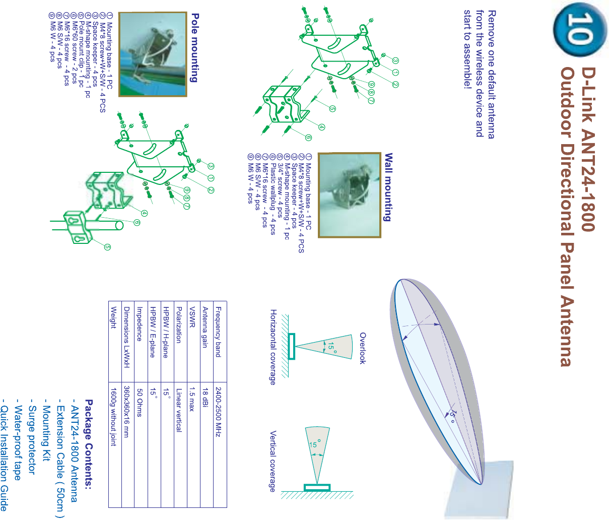
50AT
Omni
D-Link's Omni Directional Antenna offers the most cost
effective solution for extending the wireless LAN coverage
area. The antenna is fully compatible with all products and
can be used with any 2.40 to 2.4835 GHz products.
Installation:
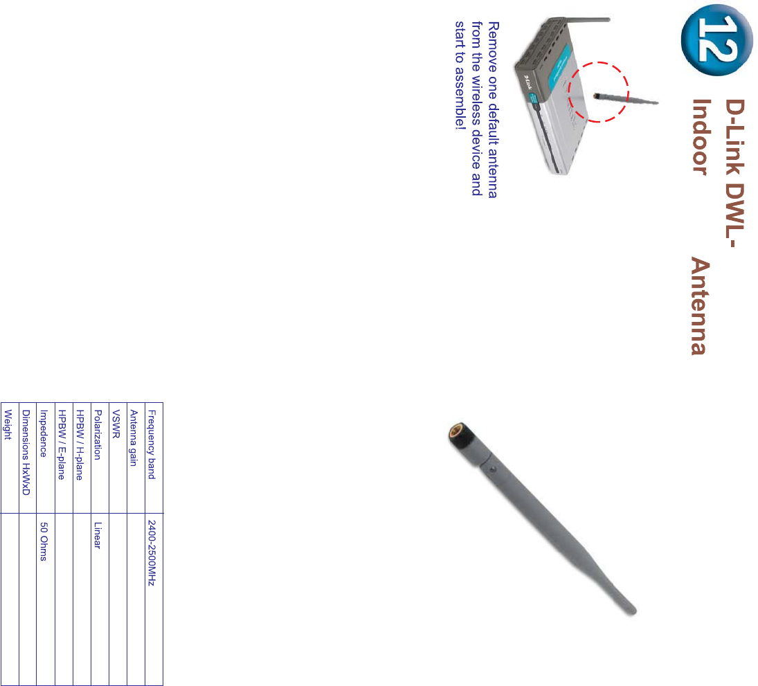
1. Remove the original antenna from your
wireless device.
2. Screw the DWL-50AT RP- SMA connector
into your wireless device.
3. Adjust the antenna to the suitable direction
for extending the wireless coverage area.
5.0dBi Typical
2.0:1 Max.
Toroidal
60 degree
nominal
197 mm(length)
29.5gw

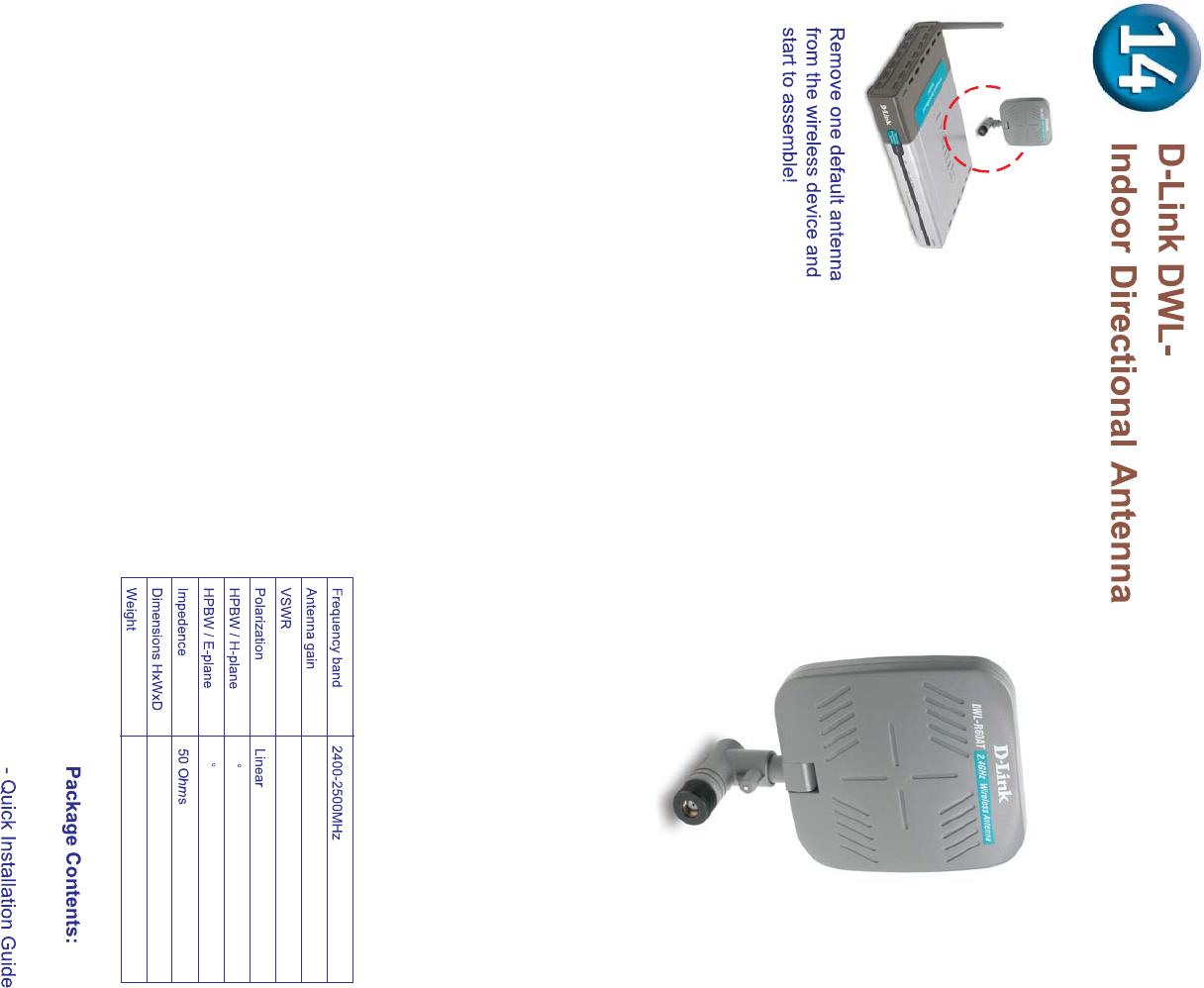
D-Link's Single Patch Flat Antenna offers the most cost
effective solution for extending the wireless LAN coverage
area. The antenna is fully compatible with all products and
can be used with any 2.40 to 2.4835 GHz products.
Installation:
1. Remove the original antenna from your
wireless device.
2. Screw the DWL-R60AT RP- SMA connector
into your wireless device.
3. Adjust the antenna to the suitable direction for
extending the wireless coverage area.
- DWL-R60AT Antenna
2.0:1 Max.
6.0dBi Typical
90
75
nominal
75gw
80x85x12.8 mm
R60AT

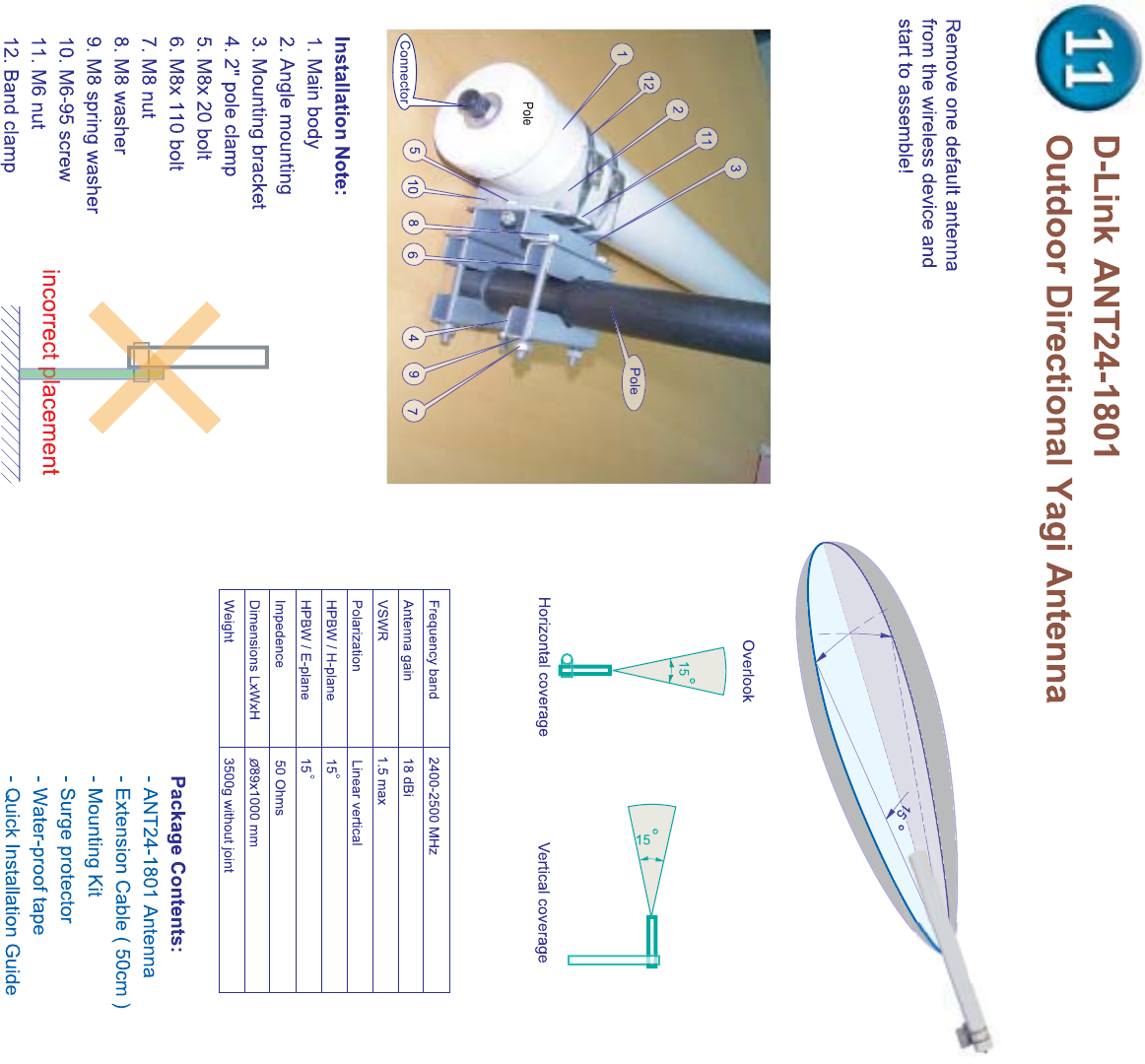
Outdoor Omni Antenna
DWL-1500

Outdoor Grid Antenna
DWL-2100
N male/RP-SMA)

Indoor/ Outdoor Antenna Table:
Model Name DWL-R60AT DWL-M60AT ANT24-0400 ANT24-0401 ANT24-0500
Signal directivity Directional Antenna Directional Antenna mni-directional mni-directional mni-directional
Application range Indoor only Indoor only Indoor only Indoor ceiling only Indoor utdoor
Gain (Without cable loss) d i d i d i . d i d i
Approximate Range at 1 Mbps * m k km
Approximate Range at 11 Mbps *
Half power beam width **
Pigtail cable length NA cm cm NA cm
Antenna fixed connector RP- A plug RP- A plug RP- A plug A ack N-ack
Surge protector for outdoors --- --- --- --- ptional
Default extension cable length NA NA NA
Default mounting configuration NA Wall desktop Wall desktop eiling Pole
Antenna-kit weight (Kg) g g g g g
Optional accessories AN -
or DWL- links
AN -
or DWL- links
AN -
or DWL- links
AN -
or DWL- links
AN -
AN - P
AN - series
.Extended range reference based on R - utput Power dbm with default cable loss
. he transmission distance range might depend on the two same spec antennas with default cable loss
P W alf Power eam Width. horiontal plane pattern, vertical plane pattern
The actual Indoor range will be effected by users’ physical environment. The above figures are reference.

Indoor/ Outdoor Antenna Table:
Model Name ANT24-0800 ANT24-0801 ANT24-1200 ANT24-1201 ANT24-1400
Signal directivity mni-directional Directional Directional Directional Directional
Application range utdoor utdoor Indoor only utdoor utdoor
Gain (Without cable loss) d i . d i d i d i d i
Approximate Range at 1 Mbps *
m m . m . m m
Approximate Range at 11 Mbps * . m . m . m
Half power Beam width **
Pigtail cable length NA cm NA cm cm
Antenna fixed connector N-ack N-ack A ack N-ack N-ack
Surge protector for outdoors Included Included --- Included Included
Default Extension Cable Length cm cm cm
Default mounting configuration Pole Wall pole Window wall Wall pole Wall pole
Antenna-kit weight (kg) . g . g g g . g
Optional accessories ltra low loss cable
or AN - series
ltra low loss cable
or AN - series
ltra low loss cable
or AN - series
ltra low loss cable
or AN - series
ltra low loss cable
or AN - series
.Extended range reference based on R - utput Power dbm with default cable loss
. he transmission distance range might depend on the two same spec antennas with default cable loss
P W alf Power eam Width. horiontal plane pattern, vertical plane pattern
The actual Indoor range will be effected by users’ physical environment. The above figures are reference.
Indoor/ Outdoor Antenna Table:
Model Name ANT24-1800 ANT24-1801 ANT24-1500 ANT24-2100
Signal directivity Directional Directional mni-directional Directional
Application range utdoor utdoor utdoor utdoor
Gain (Without cable loss) d i d i d i d i
Approximate Range at 1 Mbps * m m m m
Approximate Range at 11 Mbps * m m . m . m
Half power Beam width **
Pigtail cable length NA NA NA NA
Antenna fixed connector N-ack N-ack N-ack N-ack
Surge protector for outdoors Included Included Included Included
Default Extension Cable Length cm cm
Default mounting configuration Wall pole Pole Pole Pole
Antenna-kit weight (Kg) . g . g . g g
Optional accessories ltra low loss cable
or AN - series
ltra low loss cable
or AN - series
ltra low loss cable
or AN - series
ltra low loss cable
or AN - series
.Extended range reference based on R - utput Power dbm with default cable loss
. he transmission distance range might depend on the two same spec antennas with default cable loss
P W alf Power eam Width. horiontal plane pattern, vertical plane pattern
The actual Indoor range will be effected by users’ physical environment. The above figures are reference.
D-Link wireless antenna series are optional passive accessories for the
suitable wireless devices. Prior to your usage of the wireless antenna, please
refer the wireless device user manual, make sure the antenna connector type,
frequency band, indoor or outdoor device usage is compatible between the
antenna and device. When installing an external antenna, the total output
power (EIRP) is the sum of device output power and antenna gain minus any
connector or cable loss signal loss. We highly recommend that these products
should be installed by an experienced installer who is familiar with local building
and safety codes and where ever applicable, is licensed by the appropriate
authorities. Please note that all wireless products may cause interference
which could affect the functioning of radio navigation service or other safety
services, or otherwise seriously degrades, obstructs or repeatedly interrupts a
radiocommunications service operating in accordance with the applicable
legislation. In case of interference with radio equipments, the user may be
required to take adequate measures including repositioning the wireless
devices or changing the wireless LAN configuration.