D Link DWLG730APA1 802.11g Wireless Pocket Router / Access Point User Manual dwl700ap manual 061203
D Link Corporation 802.11g Wireless Pocket Router / Access Point dwl700ap manual 061203
D Link >
Contents
- 1. Part 1
- 2. Part 2
Part 2
31
Using the Configuration Utility in AP Client Mode (continued)
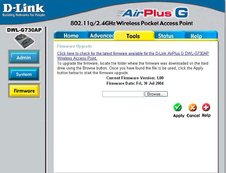
Tools > Firmware
You can upgrade the firmware of the router here. Make sure the firmware you want to use
is on the local hard drive of the computer. Check the D-Link support site for firmware
updates at http://support.dlink.com and download firmware upgrades to your hard drive.
After you have downloaded the firmware upgrade to your hard drive, click Browse to
browse the local hard drive and locate the firmware to be used for the update.
Firmware Upgrade-
Browse-
Click on the link in this screen to find out if there is updated
firmware; if so, download the new firmware to your hard drive.
After you have downloaded the new firmware, click Browse in
this window to locate the firmware update on your hard drive.
Click Apply to complete the firmware upgrade.
)
32
Using the Configuration Utility in AP Client Mode (continued)
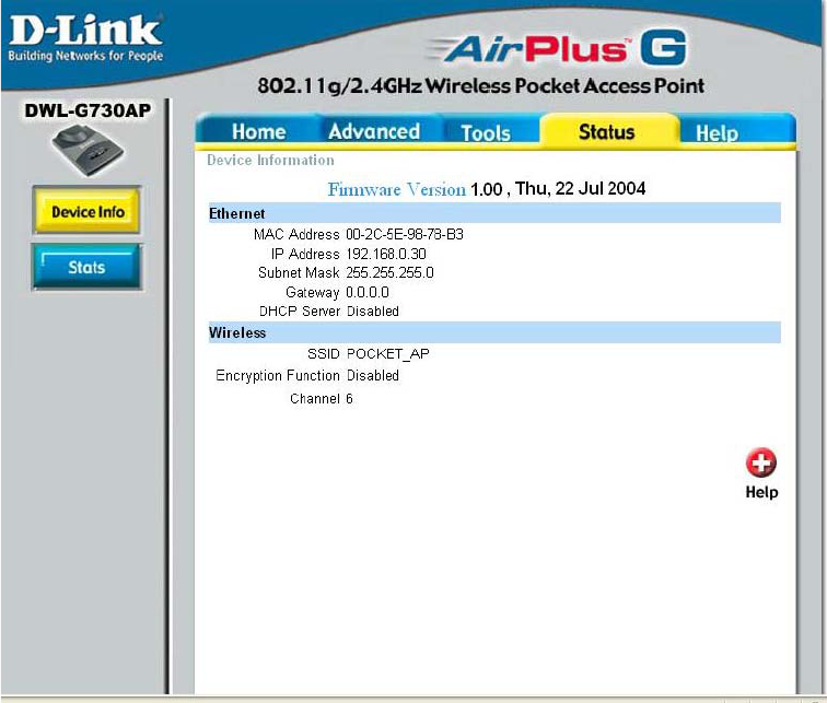
Status > Device Info
This screen displays the current firmware version, and the current wireless and Ethernet
settings of the DWL-G730AP.
33
Using the Configuration Utility in AP Client Mode (continued)
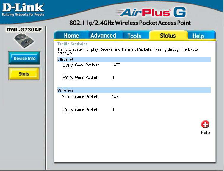
Status > Stats
This screen displays theTraffic Statistics. Here you can view the amount of packets
that pass through the DWL-G730AP on both the Ethernet and the wireless networks.
The traffic counter will reset if the device is rebooted.
)
34
Using the Configuration Utility in AP Client Mode (continued)
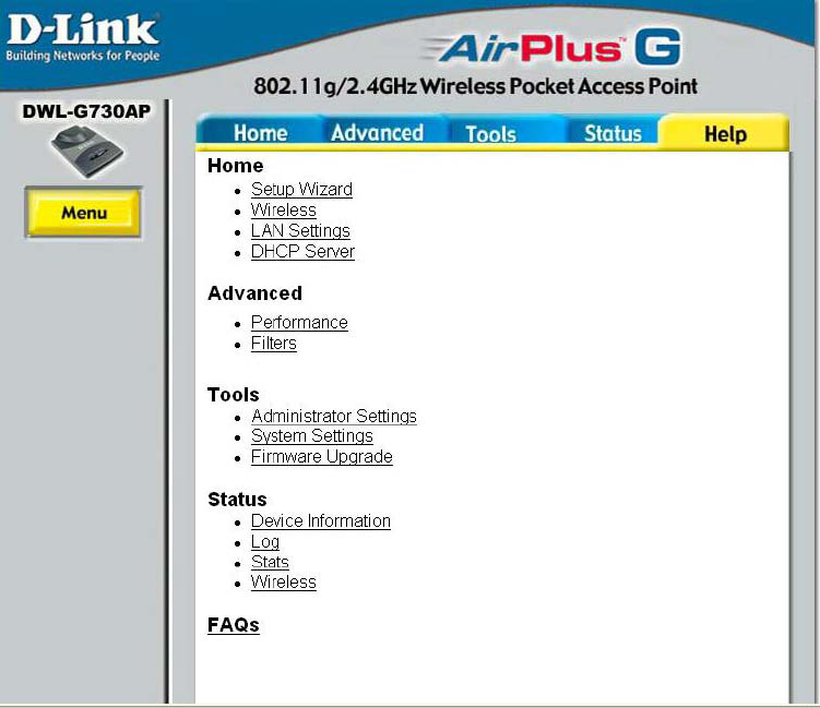
Help
The Help menu is displayed here. Click on a topic to learn more about it.
35
Using the Configuration Utility
in Router Mode
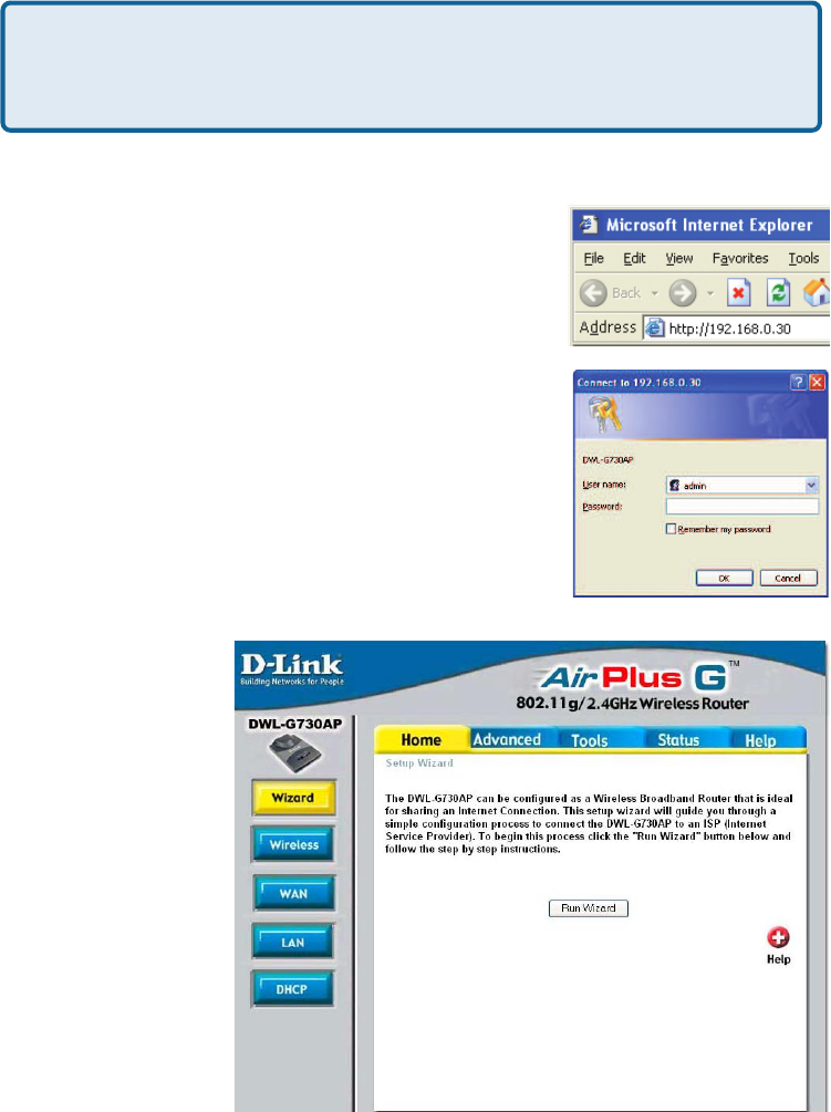
Home > Wizard
The Home>Wizard
screen will appear.
Please refer to the
Quick Installation
Guide for more
information
regarding the
Setup Wizard.
Note: if you have changed the default IP address assigned
to the DWL-G730AP, make sure to enter the correct IP
address.
Open the Web browser
Type in the IP address of the router
(http://192.168.0.30)
Type admin in the User Name field
Leave the Password blank
Click OK
To configure the DWL-G730AP in Router mode, you must be connected to the router
via a wireless network adapter. The LAN Port on the unit functions as a WAN port
when the DWL-G730AP is operating in Router mode. To run the setup wizard, establish
a wireless connection with the DWL-G730AP and follow the steps below.
To use the DWL-G730AP as a router, toggle the switch on the back of the unit.
)
36
Using the Configuration Utility in Router Mode (continued)
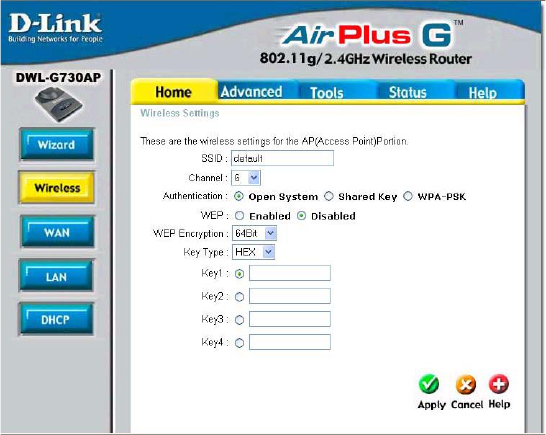
Home > Wireless
Keys 1-4- Input up to 4 WEP keys; select the one you wish to use.
Key Type- Select HEX or ASCII.
WEP Encryption- Select the level of encryption desired: 64-bit, or 128-bit.
SSID-
Service Set Identifier
(SSID) is the name
designated for a
specific wireless local
area network (WLAN).
The SSID’s factory
default setting is
default. The SSID can
be easily changed to
connect to an existing
wireless network or to
establish a new
wireless network.
WEP- Wired Equivalent Privacy (WEP) is a wireless security protocol
for Wireless Local Area Networks (WLAN). WEP provides
security by encrypting the data that is sent over the WLAN.
Select Enabled or Disabled. Disabled is the default setting.
Channel- 6 is the default channel. All devices on the network must share
the same channel.
Select Open System to communicate the key across the
network.
Select Shared Key to limit communication only to those devices
that share the same WEP settings.
Select WPA-PSK to select Wi-Fi Protected Access without a
RADIUS server.
Authentication-
37
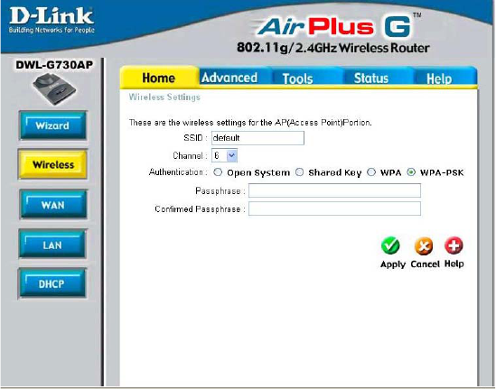
SSID: (Service Set
Identifier) default
is the default setting.
The SSID is a unique
name that identifies
a network. All
devices on a network
must share the
same SSID name in
order to
communicate on the
network. If you
choose to change
the SSID from the
default setting, input
your new SSID
name in this field.
Channel: Channel
6 is the default
channel. Input a
new number if you want to change the default setting. All devices on the network must
be set to the same channel to communicate on the network.
Authentication:
When WPA-PSK is selected fill in the following fields:
Passphrase: Enter the Passphrase here.
Confirmed Passphrase: Confirm the Passphrase here.
Apply: Click Apply to apply the changes.
Using the Configuration Utility in Router Mode (continued)
Home > Wireless > WPA-PSK
38
Using the Configuration Utility in Router Mode (continued)
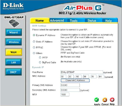
Home > WAN > Dynamic IP Address
Host Name- The Host Name is optional but may be required by some ISPs.
The default host name is the device name of the router and may
be changed.
MAC Address- The default MAC address is set to the WAN’s physical
interface MAC address on the router. It is not recommended
that you change the default MAC address unless required by
your ISP.
Clone
MAC Address- The default MAC address is set to the WAN’s physical interface
MAC address on the router. You can use the “Clone MAC
Address” button to copy the MAC address of the Ethernet Card
installed by your ISP and replace the WAN MAC address with
the MAC address of the router. It is not recommended that you
change the default MAC address unless required by your ISP.
Dynamic
IP Address- Choose Dynamic IP Address to obtain an IP address
automatically.
Primary/
Secondary DNS
Address-
MTU-
Enter a DNS address if you do not wish to use the one provided
by your ISP.
Dynamic IP Address
is selected here.
Other options include:
Static IP Address
(if your ISP provides
you with a static IP
address), PPPoE (for
most DSL users),
PPTP (for Europe) and
BigPond Cable (for
Australia).
Maximum Transmission Unit-1500 is the default setting-
Enter an MTU value only if required by your ISP. Otherwise,
leave it at the default setting.
39
Using the Configuration Utility in Router Mode (continued)
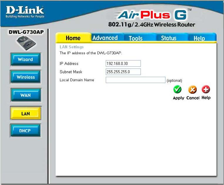
Home > LAN
LAN is short for Local Area Network. This is considered your internal network. These are
the IP settings of the LAN interface for the DWL-G730AP. These settings may be referred
to as Private settings. You may change the LAN IP address if needed. The LAN IP
address is private to your internal network and cannot be seen on the Internet.
Local Domain- This field is optional. Enter in the local domain name.
Subnet Mask- The subnet mask of the LAN interface.
The default subnet mask is 255.255.255.0
IP Address- The IP address of the LAN interface. The default IP address is:
192.168.0.30

40
Using the Configuration Utility in Router Mode (continued)
Home > DHCP
DHCP stands for Dynamic Host
Control Protocol.
The DWL-G730AP has a built-in
DHCP server. The DHCP Server will
automatically assign an IP address
to the computers on the LAN/
private network. Be sure to set
your computers to be DHCP
clients by setting their TCP/IP
settings to “Obtain an IP Address
Automatically.” When you turn
your computers on, they will
automatically load the proper TCP/
IP settings provided by the
DWL-G730AP. The DHCP server
will automatically allocate an
unused IP address from the IP
address pool to the requesting
computer. You must specify the starting and ending address of the IP address
pool.
DHCP Server- Select Enabled or Disabled. The default setting is Enabled.
Starting IP Address-The starting IP address for the DHCP server’s IP assignment.
Ending
IP Address- The ending IP address for the DHCP server’s IP assignment.
Lease Time- The length of time for the IP lease. Enter the Lease time. The
default setting is one hour.
Static DHCP is used to allow the DHCP server to assign some Static IP
addresses via specific MAC addresses.
Static DHCP- Select Enabled or Disabled.
Name-
IP-
MAC Address-
DHCP Client-
Enter a name here.
Enter the last digits of the IP address here.
Enter the MAC address of the computer that will be assigned
the Static DHCP IP address.
Use this pull-down list to list DHCP clients on your network. To
copy the MAC address into the MAC address section above,
simply select the client from the pull-down list and click the
Clone button.
41
Using the Configuration Utility in Router Mode (continued)
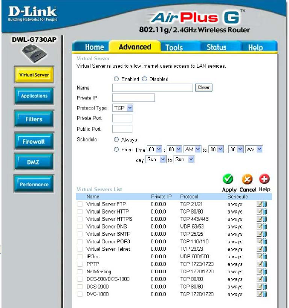
Advanced > Virtual Server
The DWL-G730AP can be configured as a virtual server so that remote users accessing
Web or FTP services via the public IP address can be automatically redirected to local
servers in the LAN (Local Area Network).
The DWL-G730AP firewall feature filters out unrecognized packets to protect your LAN
network so all computers networked with the DWL-G730AP are invisible to the outside
world. If you wish, you can make some of the LAN computers accessible from the
Internet by enabling Virtual Server. Depending on the requested service, the DWL-G730AP
redirects the external service request to the appropriate server within the LAN network.
The DWL-G730AP is also capable of port-redirection meaning incoming traffic to a
particular port may be redirected to a different port on the server computer.
Each virtual service that is created will be listed at the bottom of the screen in the Virtual
Servers List. There are pre-defined virtual services already in the table. You may use
them by enabling them and assigning the server IP to use that particular virtual service.
42
Using the Configuration Utility in Router Mode (continued)
Advanced > Virtual Server (continued)
Example #1:
Protocol Type- The protocol used for the virtual service.
Public Port- The port number on the WAN (Wide Area Network) side that will
be used to access the virtual service.
Private Port- The port number of the service used by the Private IP computer.
Schedule- The schedule of time when the virtual service will be enabled.
The schedule may be set to Always, which will allow the
particular service to always be enabled. If it is set to From,
select the time frame for the service to be enabled. If the
system time is outside of the scheduled time, the service will
be disabled.
Virtual Server- Select Enabled or Disabled.
Name- Enter the name referencing the virtual service.
Private IP- The server computer in the LAN (Local Area Network) that will be
providing the virtual services.
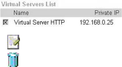
If you have a Web server that you wanted Internet users to
access at all times, you would need to enable it. Web
(HTTP) server is on LAN (Local Area Network) computer
192.168.0.25. HTTP uses port 80, TCP.
Name: Web Server
Private IP: 192.168.0.25
Protocol Type: TCP
Private Port: 80
Public Port: 80
Schedule: always
43
Using the Configuration Utility in Router Mode (continued)
Advanced > Virtual Server (continued)
Example #2:
If you have an FTP server that you wanted Internet users to access by WAN port 2100
and only during the weekends, you would need to enable it as such. FTP server is on
LAN computer 192.168.0.30. FTP uses port 21, TCP.
Name: FTP Server
Private IP: 192.168.0.30
Protocol Type: TCP
Private Port: 21
Public Port: 2100
Schedule: From: 01:00AM to 01:00AM, Sat to Sun
Click on this icon to edit the virtual service
Click on this icon to delete the virtual service
All Internet users who want to access this FTP Server
must connect to it from port 2100. This is an example of
port redirection and can be useful in cases where there
are many of the same servers on the LAN network.
44
Using the Configuration Utility in Router Mode (continued)
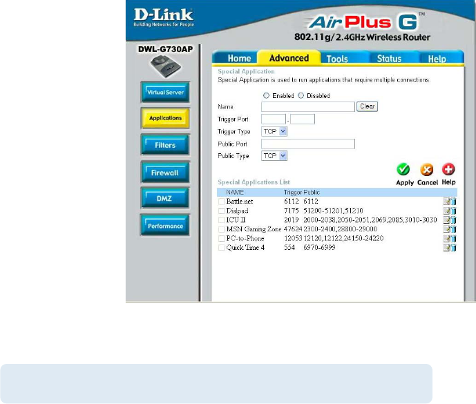
Advanced > Applications
Some applications such
as Internet gaming, video
conferencing, Internet
telephony and others,
require multiple
connections. These
applications save
difficulties working
through NAT (Network
Address Translation).
Special Applications
makes some of these
applications work with
the DWL-G730AP. If you
need to run applications
that require multiple
connections, specify the
port normally associated
with an application in the
“Trigger Port” field, select
the protocol type as TCP
or UDP, then enter the public ports associated with the trigger port to open them for
inbound traffic.
The DWL-G730AP provides some predefined applications in the table on the bottom of
the Web page. Select the application you want to use and enable it.
Name: This is the name referencing the special application.
Trigger Port: This is the port used to trigger the application. It can be either
a single port or a range of ports.
Trigger Type: This is the protocol used to trigger the special application.
Public Port: This is the port number on the WAN side that will be used to
access the application. You may define a single port or a
range of ports. You can use a comma to add multiple ports or
port ranges.
Public Type: This is the protocol used for the special application.
Note! Only one PC can use each Special Application tunnel.
Special Applications List
45
Using the Configuration Utility in Router Mode (continued)
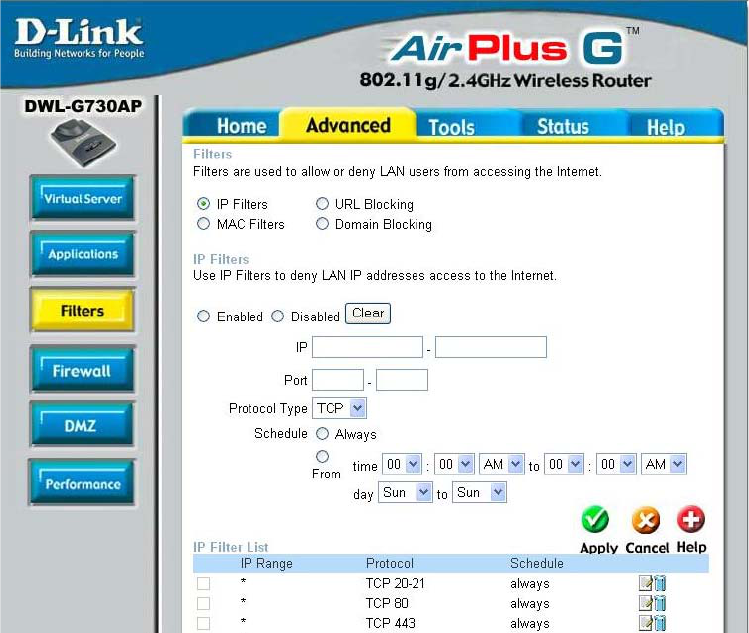
Advanced > Filters > IP Filters
Filters are used to deny or allow LAN (Local Area Network) computers from accessing
the Internet. The DWL-G730AP can be setup to deny internal computers by their IP or
MAC addresses. The DWL-G730AP can also block users from accessing restricted
web sites.
This is the schedule of time when the IP Filter will be enabled.
Schedule:
Select the protocol type
Protocol Type:
Use IP Filters to deny LAN IP addresses from accessing the
Internet. You can deny specific port numbers or all ports for
the specific IP address.
IP Filters:
The single port or port range that will be denied access to the
Internet.
Port:
The IP address of the LAN computer that will be denied
access to the Internet.
IP:
46
Using the Configuration Utility in Router Mode (continued)
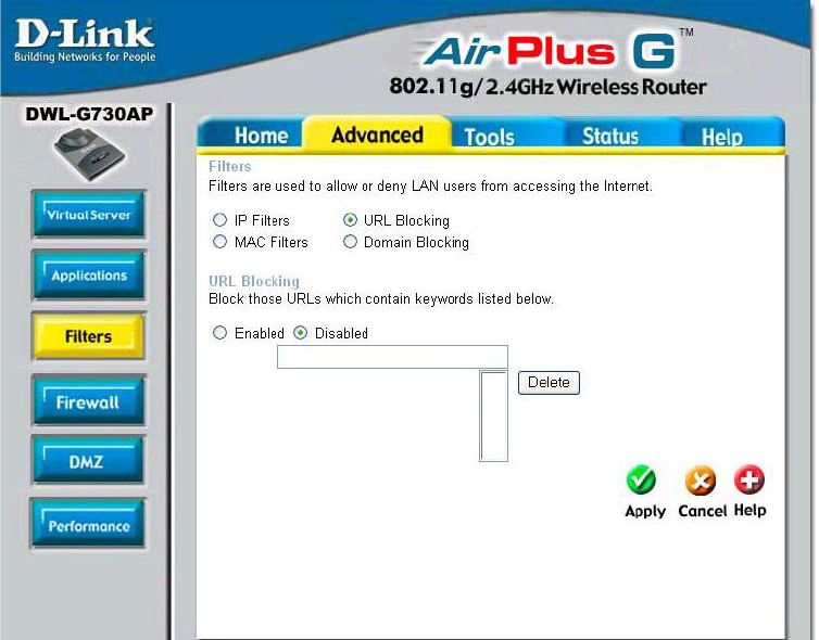
Advanced > Filters > URL Blocking
Select Enable or Disable. Enter the words or word contained
in the URL that you wish to block. Click Apply to activate the
URL blocking.
URL Blocking:
Select the URL block that you want to delete. Click
Delete.
Delete:
Click Apply to save changes.
Apply:
47
Using the Configuration Utility in Router Mode (continued)
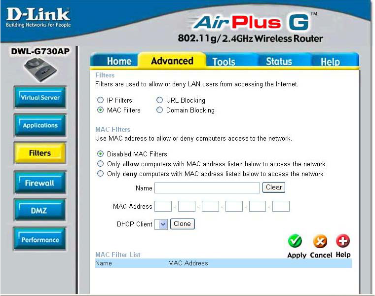
Advanced > Filters > MAC Filters
Click to Disable MAC Filters.
Disable MAC
Filters:
Allow only those devices with the listed MAC addresses
access to the network.
Allow:
Deny the devices that are listed from accessing the network.
Deny:
Enter a name for the device.
Name:
Click Clear to erase the name.
Clear:
Enter the MAC address manually.
MAC Address:
Select the DHCP Client from the pull-down list and click
Clone to enter the MAC address into the list.
Clone:
Click Apply to save the changes.
Apply:
48
Using the Configuration Utility in Router Mode (continued)
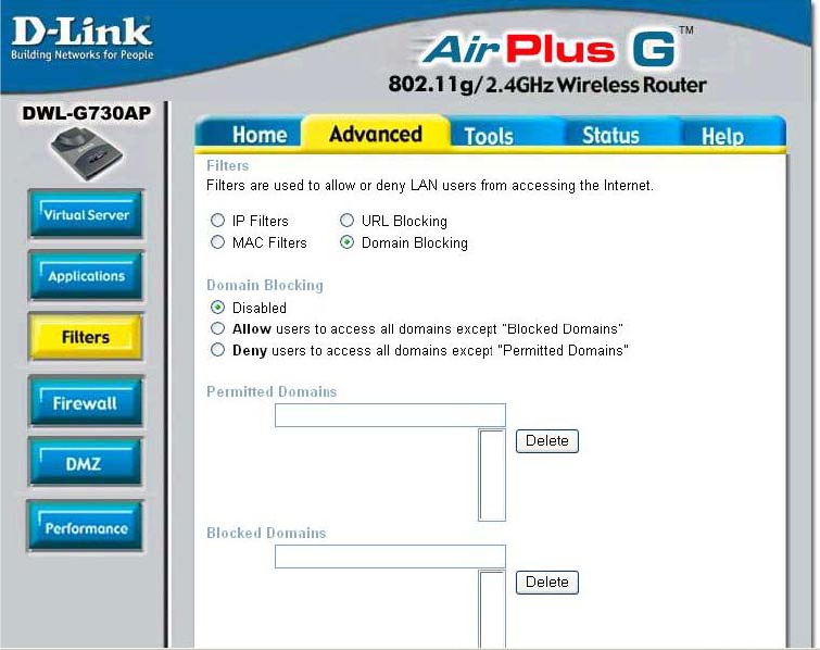
Advanced > Filters > Domain Blocking
Click Disable to disable domain blocking.
Disable:
Click Allow to allow access to all domains except Blocked
Domains.
Allow:
Click Deny to deny access to all domains except Permitted
Domains.
Deny:
Enter the permitted domains here. Click Apply.
Permitted
Domains:
Enter the blocked domains here. Click Apply.
Blocked
Domains:
Select a domain from either the permitted or blocked domain
list, and click Delete to delete this domain.
Delete:
49
Using the Configuration Utility in Router Mode (continued)
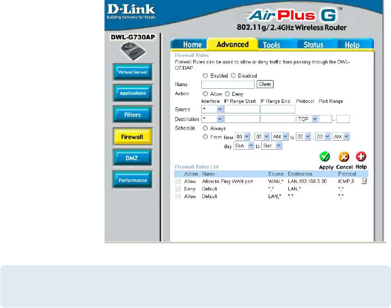
Advanced > Firewall
Firewall Rules is
an advanced feature
used to deny or
allow traffic from
passing through the
DWL-G730AP. It
works in the same
way as IP Filters
with additional
settings. You can
create more detailed
access rules for the
DWL-G730AP.
When virtual
services are created
and enabled, it will
also display in
Firewall Rules.
Firewall Rules
contain all network
firewall rules
pertaining to IP
(Internet Protocol).
Firewall Rules- Enable or disable the Firewall
Name- Enter the name
Action- Allow or Deny
Source- Enter the IP Address range
Schedule- Select Always or enter the Time Range.
Destination- Enter the IP Address range; the Protocol;
and the Port Range
Note:
The DWL-G730AP MAC Address filtering rules have precedence over
the Firewall Rules.
In the Firewall Rules List at the bottom of the screen,rules are prioritized from the top
(highest priority) to the bottom (lowest priority.)
50
Using the Configuration Utility in Router Mode (continued)
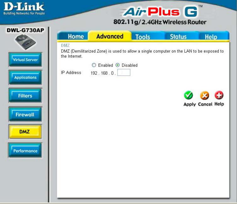
Advanced > DMZ
If you have a client PC that cannot run Internet applications properly from behind the
DWL-G730AP, then you can set the client up for unrestricted Internet access. Allowing
a computer to be exposed to the Internet, this feature is useful for gaming purposes.
Enter the IP address of the internal computer that will be the DMZ host. Using the DMZ
(Demilitarized Zone) feature may expose your local network to a variety of security
risks, so only use this option as a last resort.
DMZ- Enable or Disable the DMZ. The DMZ (Demilitarized Zone)
allows a single computer to be exposed to the internet. By
default the DMZ is disabled.
IP Address- Enter the IP Address of the computer to be in the DMZ
30
51
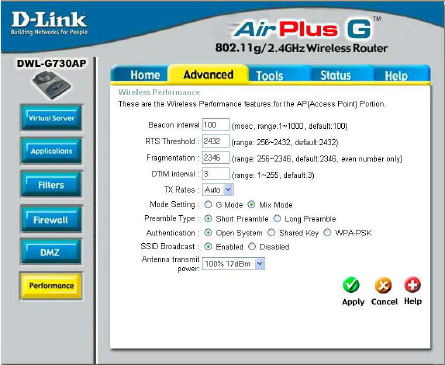
Beacon Interval: Beacons are
packets sent by an access point
to synchronize a wireless network.
Specify a beacon interval value.
Default (100) is recommended.
RTS Threshold: This value
should remain at its default
setting of 2432. If you encounter
inconsistent data flow, only
minor modifications to the value
range between 256 and 2432
are recommended.
Fragmentation: This value
should remain at its default
setting of 2346. If you experience
a high packet error rate, you may slightly increase your fragmentation threshold within
the value range of 256 to 2346. Setting the fragmentation threshold too low may result in
poor performance.
DTIM Interval (Beacon Rate): (Delivery Traffic Indication Message) Enter a value
between 1 and 255 (default is 3) for the Delivery Traffic Indication Message (DTIM.) A
DTIM is a countdown informing clients of the next window for listening to broadcast and
multicast messages.
TX Rates: Select the transmission rate for the network. The default setting is Auto.
Mode Setting: For utmost speed, select G Mode to include only 802.11g devices in
your network. Select Mix Mode to include 802.11g and 802.11b devices in your network.
Preamble: Short Preamble is the default setting. (High traffic networks should use
the shorter preamble type.) The preamble defines the length of the CRC block (Cyclic
Redundancy Check is a common technique for detecting data transmission errors) used
in communication between the access point and the wireless network adapters.
Using the Configuration Utility in Router Mode (continued)
Advanced > Performance
SSID Broadcast: (Service Set Identifier) Enable or Disable (default) the broadcast of
the SSID name across the network. SSID is a name that identifies a wireless network.
All devices on a network must use the same SSID to establish communication.
Antenna Transmit Power: Select the transmission power of the antenna. Limiting
antenna power can be useful for security purposes.
Authentication:
Select Open System to communicate the key across the network.
Select Shared Key to limit communication only to those devices that share the
same WEP settings.
Select WPA-PSK to select Wi-Fi Protected Access without a RADIUS server.
52
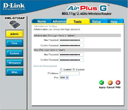
Using the Configuration Utility in Router Mode (continued)
Tools > Admin
At this page, the DWL-G730AP administrator can change the system password. There
are two accounts that can access the router’s Web-management interface. They are
admin and user. Admin has read/write access while user has read-only access. The
user can only view the settings but cannot make any changes.
Remote Management- Remote management allows the DWL-G730AP to be
configured from the Internet by a Web browser. A username and password is still required
to access the Web-management interface. In general, only a member of your network
can browse the built-in Web pages to perform Administrator tasks. This feature enables
you to perform Administrator tasks from the remote (Internet) host.
IP Address- The Internet IP address of the computer that has access to the router. If
you input an asterisk (*) into this field, then any computer will be able to access the
router. Putting an asterisk (*) into this field would present a security risk and is not
recommended.
Port- The port number used to access the router.
Example- http://x.x.x.x:8080 where x.x.x.x is the WAN IP address of the router and
8080 is the port used for the Web-mangement interface.
Administrator-
Password-
admin is the Administrator login name
Enter the password and enter again to confirm
User-
Password-
user is the User login name
Enter the password and enter again to confirm
53
Using the Configuration Utility in Router Mode (continued)
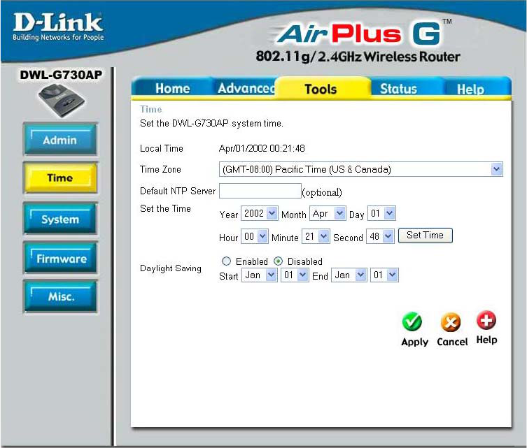
Tools > Time
Time Zone- Select the time zone from the pull-down menu.
Daylight
Saving- To select daylight saving time manually, select enabled or
disabled, and enter a start date and an end date for daylight
saving time.
Set the Time- To manually input the time, enter the values in these fields for
the year, month, day, hour, minute, and second. Click Set Time.
Default
NTP Server- NTP is short for Network Time Protocol. NTP synchronizes
computer clock times in a network of computers.
This field is optional.
54
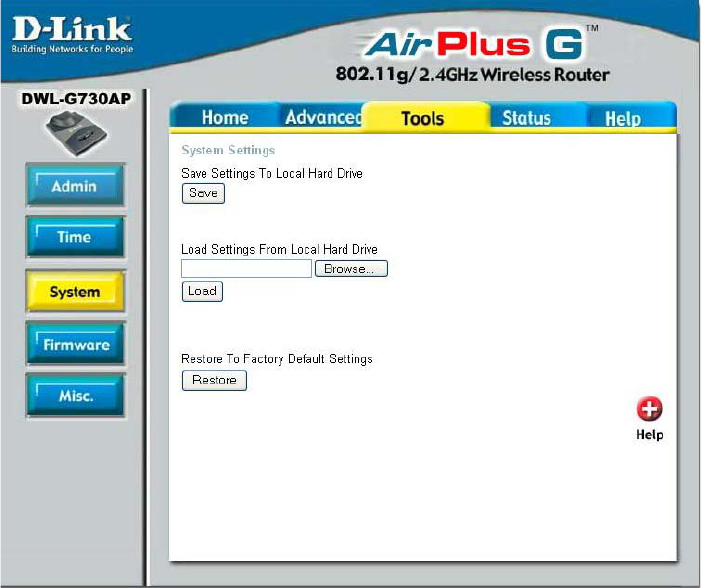
Using the Configuration Utility in Router Mode (continued)
Tools > System
The current system settings can be saved as a file onto the local hard drive. To reload a
system settings file, click on Browse to browse the local hard drive and locate the
system file to be used.
Click Save to save the current settings to the local hard drive
Click Browse to find the settings, then click Load
Save Settings to
Local Hard Drive-
Load Settings from
Local Hard Drive-
Restore to Factory
Default Settings- Click Restore to restore the factory default settings
55
Using the Configuration Utility in Router Mode (continued)
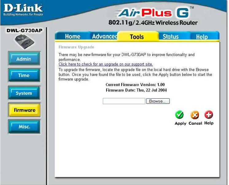
Tools > Firmware
You can upgrade the firmware of the router here. Make sure the firmware you want to use
is on the local hard drive of the computer. Please check the D-Link support site for
firmware updates at http://support.dlink.com. You can download firmware upgrades to
your hard drive from the D-Link support site. After you have downloaded the firmware
upgrade to your hard drive, click Browse to browse the local hard drive and locate the
firmware to be used for the update.
Firmware Upgrade-
Browse-
Click on the link in this screen to find out if there is updated
firmware; if so, download the new firmware to your hard drive.
After you have downloaded the new firmware, click Browse in
this window to locate the firmware update on your hard drive.
Click Apply to complete the firmware upgrade.
56
Using the Configuration Utility in Router Mode (continued)
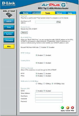
Tools > Misc
Ping Test-
Restart
Device-
Block
WAN
Ping-
Discard Ping from WAN side
VPN
Pass
Through-
PPTP- select Enabled or Disabled
IPSec- select Enabled or Disabled
The ping test is used to send ping
packets to test if a computer is on the
Internet. Enter the IP address that you
wish to ping, and click Ping.
If you choose to block WAN ping, the
WAN IP address of the DWL-G730AP
will not respond to pings. Blocking the
ping may provide some extra
security from hackers.
The DWL-G730AP supports VPN (Virtual Private Network) pass-through
for both PPTP (Point-to-Point Tunneling Protocol) and IPSec
(IP Security). Once VPN pass-through is enabled, there is no need to
open up virtual services. Multiple VPN connections can be made through
the DWL-G730AP. This is useful when you have many VPN clients on the
LAN network.
Click Reboot to restart the
DWL-G730AP.
Click Enabled to block the WAN ping
UPNP-
Gaming
Mode-
To use the Universal Plug and Play fea-
ture click on Enabled. UPnP
provides compatibility with networking
equipment, software and peripherals of
the over 400 vendors that cooperate in the Plug and Play forum.
Gaming mode allows a form of pass-through for certain Internet games. If
you are using Xbox, Playstation2 or a PC, make sure you are using the
latest firmware and Gaming Mode is enabled. To utilize Gaming Mode,
click Enabled. If you are not using a Gaming application, it is
recommended that you Disable Gaming Mode.
Dynamic
DNS- Dynamic Domain Name System is a method of keeping a domain name
linked to a changing IP Address. This is a useful feature since many
computers do not use a static IP address. Enter the IP address and Host
Name of the Domain Name Server. Enter your Username and Password.
WAN select
to 10/
100Mbps- Select the data rate : 10Mbps, 100Mbps or 10/100Mbps Auto.
Apply- Click Apply to save the changes.
57
Using the Configuration Utility in Router Mode (continued)
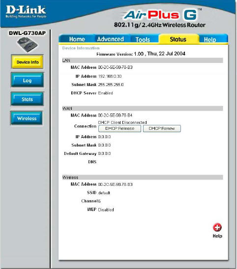
Status > Device Info
This page displays the current
information for the
DWL-G730AP. It will display
the LAN, WAN and MAC
address information.
If your WAN connection is set
up for a Dynamic IP address
then a Release button and a
Renew button will be
displayed. Use Release to
disconnect from your ISP and
use Renew to connect to your
ISP.
If your WAN connection is set
up for PPPoE, a Connect
button and a Disconnect
button will be displayed. Use
Disconnect to drop the PPPoE
connection and use Connect to
establish the PPPoE
connection.
This window will display the following settings:
MAC address of the DWL-G730AP
Client connection (DHCP or PPoE client status)
IP address: WAN/Public IP address
Subnet Mask: WAN/Public subnet mask
Gateway: WAN/Public Gateway IP address
Domain Name Server: WAN/Public DNS IP address
Wireless
MAC address of the DWL-G730AP
IP Address: LAN/Private IP address of the DWL-G730AP
Subnet Mask: LAN/Private subnet mask
DHCP Server (Enabled or Disabled)
WAN
LAN
MAC Address: Displays the MAC address
SSID: Displays the current SSID
Channel: Displays the current channel
WEP: indicates whether WEP is enabled or disabled
58
Using the Configuration Utility in Router Mode (continued)
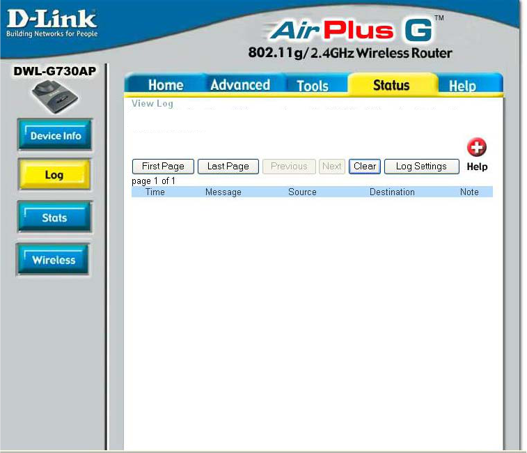
Status > Log
View Log displays the activities occurring on the DWL-G730AP.
Click on Log Settings for advance features.
The DWL-G730AP keeps a running log of events and activities. If the device is rebooted,
the logs are automatically cleared. You may save the log files under Log Settings.
View Log- First Page - The first page of the log
Last Page - The last page of the log
Previous - Moves back one log page
Next - Moves forward one log page
Clear - Clears the logs completely
Log Settings - Brings up the page to configure the log
59
Using the Configuration Utility in Router Mode (continued)
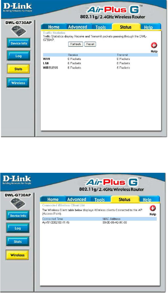
Status > Stats
Status > Wireless
This screen displays
theTraffic Statistics.
Here you can view the
amount of packets that
pass through the
DWL-G730AP on both
the WAN and the LAN
ports.
The traffic counter will
reset if the device is
rebooted.
Click Refresh to view
the latest statistics.
Click Reset to reset.
The wireless client
table displays a list of
current connected
wireless clients. This
table also displays the
connection time and
MAC address of the
connected wireless
client.
Click on Help at any
time, for more
information.
60
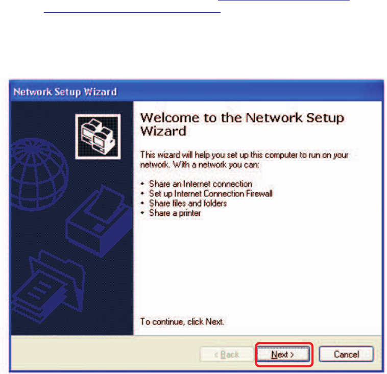
Using the Network Setup Wizard in Windows XP
In this section you will learn how to establish a network at home or work, using
Microsoft Windows XP.
Note: Please refer to websites such as http://www.homenethelp.com
and http://www.microsoft.com/windows2000 for information about networking
computers using Windows 2000, Me or 98SE.
Go to Start>Control Panel>Network Connections
Select Set up a home or small office network
Networking Basics
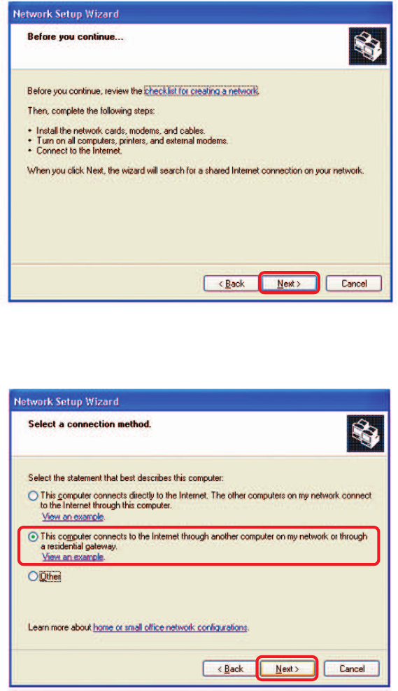
When this screen appears, click Next.
61
Please follow all the instructions in this window:
Networking Basics (continued)
Click Next.
In the following window, select the best description of your computer. If your
computer connects to the internet through a gateway/router, select the second option
as shown.
Click Next.
62
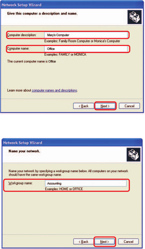
Enter a Computer description and a Computer name (optional.)
Networking Basics (continued)
Click Next.
Enter a Workgroup name. All computers on your network should have the same
Workgroup name.
Click Next.
63
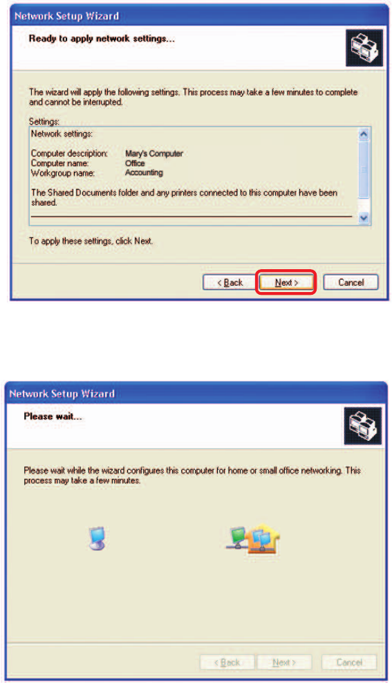
Please wait while the Network Setup Wizard applies the changes.
Networking Basics (continued)
When the changes are complete, click Next.
Please wait while the Network Setup Wizard configures the computer.
This may take a few minutes.
64
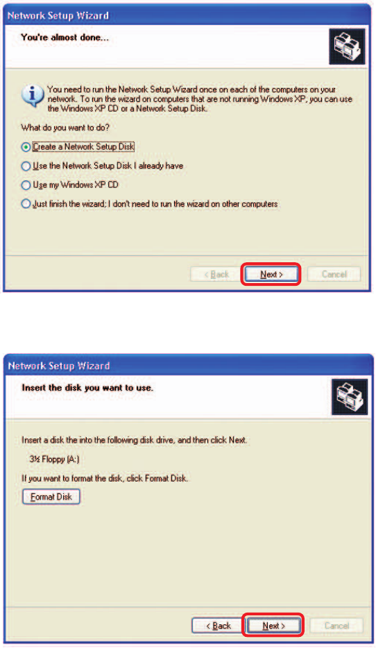
Networking Basics (continued)
In the window below, select the option that fits your needs. In this example, Create a
Network Setup Disk has been selected. You will run this disk on each of the
computers on your network. Click Next.
Insert a disk into the Floppy Disk Drive, in this case drive A.
65
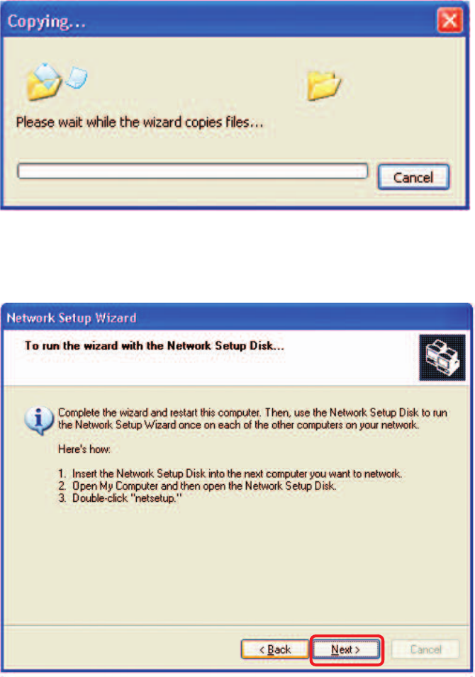
Networking Basics (continued)
Please read the information under Here’s how in the screen below. After you com-
plete the Network Setup Wizard you will use the Network Setup Disk to run the
Network Setup Wizard once on each of the computers on your network. To continue
click Next.
Please wait while the Network Setup Wizard copies the files.
66
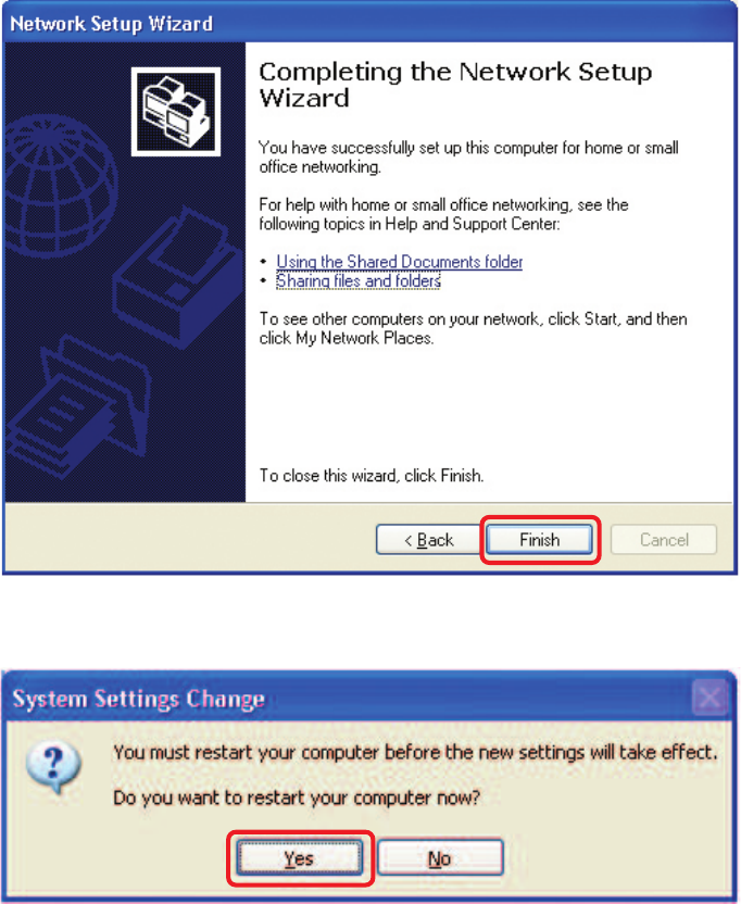
Networking Basics (continued)
Please read the information on this screen, then click Finish to complete the
Network Setup Wizard.
The new settings will take effect when you restart the computer. Click Yes to restart
the computer.
You have completed configuring this computer. Next, you will need to run the Network
Setup Disk on all the other computers on your network. After running the Network
Setup Disk on all your computers, your new wireless network will be ready to use.
67
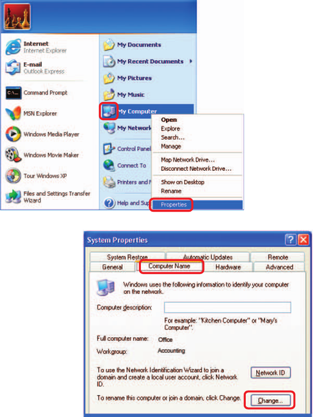
Networking Basics (continued)
Naming your Computer
To name your computer, please follow these directions:In Windows XP:
Click Start (in the lower left corner of the screen).
Right-click on My Computer.
Select Properties and click.
Select the Computer
Name Tab in the System
Properties window.
You may enter a Computer
Description if you wish; this
field is optional.
To rename the computer
and join a domain, Click
Change.
68
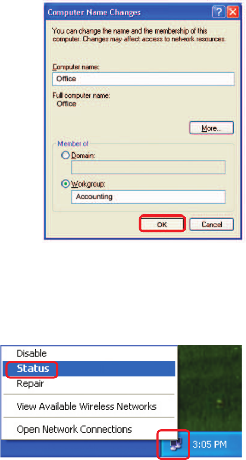
Networking Basics (continued)
Naming your Computer
In this window, enter the
Computer name.
Select Workgroup and enter
the name of the Workgroup.
All computers on your network
must have the same
Workgroup name.
Click OK.
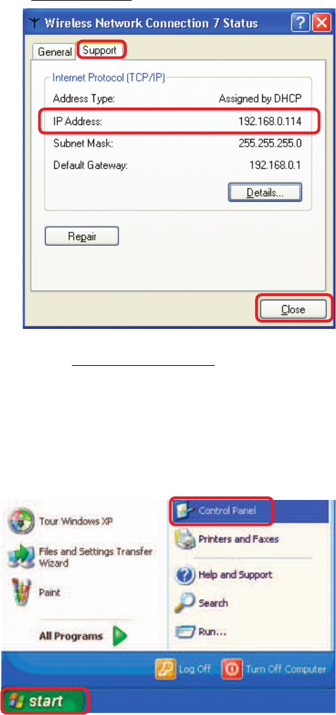
Checking the IP Address in Windows XP
The wireless adapter-equipped computers in your network must be in the same IP
Address range (see Getting Started in this manual for a definition of IP Address Range.)
To check on the IP Address of the adapter, please do the following:
Right-click on the
Local Area
Connection icon
in the task bar.
Click on Status.
69
Networking Basics (continued)
Checking the IP Address in Windows XP
This window will appear.
Click the
Support tab.
Click Close.
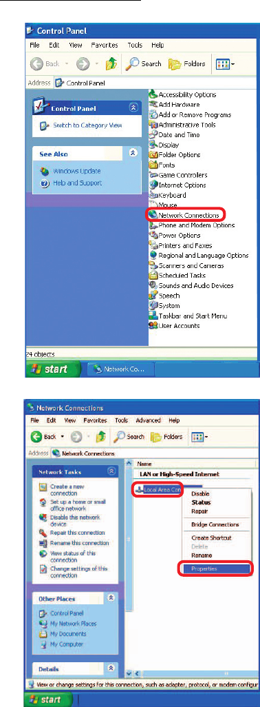
Assigning a Static IP Address in Windows XP/2000
Note: Residential Gateways/Broadband Routers will automatically assign IP Addresses
to the computers on the network, using DHCP (Dynamic Host Configuration Protocol)
technology. If you are using a DHCP-capable Gateway/Router you will not need to
assign Static IP Addresses.
If you are not using a DHCP capable Gateway/Router, or you need to assign a Static IP
Address, please follow these instructions:
Go to Start.
Double-click on
Control Panel.
70
Networking Basics (continued)
Assigning a Static IP Address in Windows XP/2000
Double-click on
Network
Connections.
Double-click on
Properties.
Right-click on Local Area
Connections.
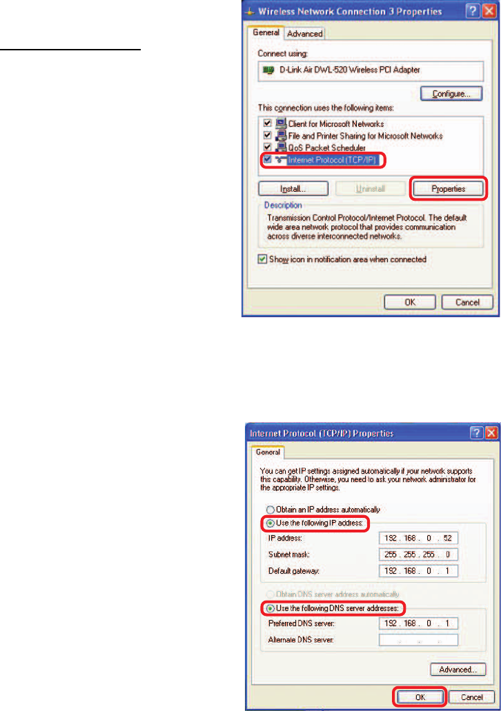
71
Select Use the following
DNS server address. Enter
the LAN IP address of the
wireless router. (D-Link
wireless routers have a LAN
IP address of 192.168.0.1)
Networking Basics (continued)
Assigning a Static IP Address
in Windows XP/2000
You have completed the assignment of a static IP address. (You do not need to assign
a static IP address if you have a DHCP-capable router.)
IP Address:
e.g., 192.168.0.2
Subnet Mask:
255.255.255.0
Default Gateway:
In the window below, select Use the following IP address. Input your IP
address and subnet mask. (The IP addresses on your network must be
within the same range. For example, if one computer has an IP address of
192.168.0.2, the other computers should have IP addresses that are
sequential, like 192.168.0.3 and 192.168.0.4. The subnet mask must be
the same for all the computers on the network.)
Click OK.
Enter the LAN IP address of
the wireless router. (D-Link
wireless routers have a LAN IP
address of 192.168.0.1)
Click on Internet Protocol
(TCP/IP).
Click Properties.
Select Use the following IP
address in the Internet
Protocol (TCP/IP) Properties
window (shown below)
72
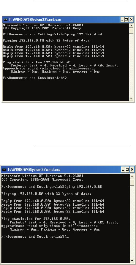
Networking Basics (continued)
Checking the Wireless Connection by Pinging in Windows XP/2000
Checking the Wireless Connection by Pinging in Windows Me /98SE
Go to Start > Run >
type cmd. A window
similar to this one
will appear. Type
ping
xxx.xxx.xxx.xxx,
where xxx is the IP
address of the
wireless router or
access point. A good
wireless connection
will show four replies
from the wireless
router or access
point, as shown.
Go to Start > Run
> type command.
A window similar to
this will appear.
Type ping
xxx.xxx.xxx.xxx
where xxx is the IP
address of the
wireless router or
access point. A
good wireless
connection will
show four replies
from the wireless
router or access
point, as shown.
73
Standards
• IEEE 802.11b
• IEEE 802.11g
• IEEE 802.3
• IEEE 802.3u
Device Management
• Web-Based – Internet Explorer v6 or later; Netscape Navigator v7 or later; or other
Java-enabled browsers.
Data Rate
For 802.11g:
• 54, 48, 36, 24, 18, 12, 9 and 6Mbps
For 802.11b:
• 11, 5.5, 2, and1Mbps
Security
• 64-, 128-bit WEP
• WPA – Wi-Fi Protected Access
• MAC Address Filtering
• SSID Broadcast Disable
Wireless Frequency Range
• 2.412GHz to 2.462GHz
Wireless Operating Range*
802.11g (Full Power with internal antenna)
Outdoors:
• 164ft (50m) @ 54Mbps
• 492ft (150m) @ 11Mbps
• 656ft (200m) @ 6Mbps
Power
• External Power Supply: DC 5V/1.2A
* Environmental factors may adversely affect wireless range
Technical Specifications
74
Radio and Modulation Type
For 802.11g:
OFDM:
• BPSK @ 6 and 9Mbps
• QPSK @ 12 and 18Mbps
• 16QAM @ 24 and 36Mbps
• 64QAM @ 48 and 54Mbps
DSSS:
• DBPSK @ 1Mbps
• DQPSK @ 2Mbps
• CCK @ 5.5 and 11Mbps
For 802.11b:
DSSS:
• DBPSK @ 1Mbps
• DQPSK @ 2Mbps
• CCK @ 5.5 and 11Mbps
Wireless Transmit Power
Typical RF Output Power at each Data Rate
For 802.11g:
• 31mW (15dBm) @ 54Mbps
• 40mW (16dBm) @ 48Mbps
• 40mW (16dBm) @ 36, 24, 18, 12, 9, and 6Mbps
For 802.11b:
• 50mW (17dBm) @ 11, 5.5, 2, and 1Mbps
Receiver Sensitivity
For 802.11g:
• 6Mbps: -87dBm
• 9Mbps: -85dBm
• 12Mbps: -82dBm
• 18Mbps: -81dBm
• 24Mbps: -80dBm
• 36Mbps: -79dBm
• 48Mbps: -71dBm
• 54Mbps: -69dBm
For 802.11b:
• 1Mbps: -90dBm
• 2Mbps: -90dBm
• 5.5Mbps: -86dBm
• 11Mbps: -85dBm
Technical Specifications (continued)
75
LEDs
• Power
• LAN
• WLAN
Temperature
• Operating: 32ºF to 131ºF (0ºC to 55ºC)
• Storing: -4ºF to 149ºF (-20ºC to 65ºC)
Humidity
• Operating: 10%~90% (non-condensing)
• Storing: 5%~95% (non-condensing)
Technical Specifications (continued)
Certifications
• FCC
• CE
Dimensions
• L = 3.15 inches (80mm)
• W = 2.36 inches (60mm)
• H = 0.67 inches (17mm)
Weight
• 0.11 lbs (50g)
Warranty
• 1 Year

76
Technical Support
You can find software updates and user documentation on the D-Link website.
D-Link provides free technical support for customers within the United States and
within Canada for the duration of the warranty period on this product.
U.S. and Canadian customers can contact D-Link technical support through our
website, or by phone.
Tech Support for customers within the United States:
D-Link Technical Support over the Telephone:
(877) 453-5465
24 hours a day, seven days a week.
D-Link Technical Support over the Internet:
http://support.dlink.com
email:support@dlink.com
Tech Support for customers within Canada:
D-Link Technical Support over the Telephone:
(800) 361-5265
Monday to Friday 7:30am to 12:00am EST
D-Link Technical Support over the Internet:
http://support.dlink.ca
email:support@dlink.ca

77
Subject to the terms and conditions set forth herein, D-Link Systems, Inc. (“D-Link”) provides this Limited
warranty for its product only to the person or entity that originally purchased the product from:
•D-Link or its authorized reseller or distributor and
•Products purchased and delivered within the fifty states of the United States, the District of Columbia,
U.S. Possessions or Protectorates, U.S. Military Installations, addresses with an APO or FPO.
Limited Warranty: D-Link warrants that the hardware portion of the D-Link products described
below will be free from material defects in workmanship and materials from the date of original retail
purchase of the product, for the period set forth below applicable to the product type (“Warranty
Period”), except as otherwise stated herein.
1-Year Limited Warranty for the Product(s) is defined as follows:
•Hardware (excluding power supplies and fans) One (1) Year
•Power Supplies and Fans One (1) Year
•Spare parts and spare kits Ninety (90) days
D-Link’s sole obligation shall be to repair or replace the defective Hardware during the Warranty Period
at no charge to the original owner or to refund at D-Link’s sole discretion. Such repair or replacement will
be rendered by D-Link at an Authorized D-Link Service Office. The replacement Hardware need not be
new or have an identical make, model or part. D-Link may in its sole discretion replace the defective
Hardware (or any part thereof) with any reconditioned product that D-Link reasonably determines is
substantially equivalent (or superior) in all material respects to the defective Hardware. Repaired or
replacement Hardware will be warranted for the remainder of the original Warranty Period from the date
of original retail purchase. If a material defect is incapable of correction, or if D-Link determines in its sole
discretion that it is not practical to repair or replace the defective Hardware, the price paid by the original
purchaser for the defective Hardware will be refunded by D-Link upon return to D-Link of the defective
Hardware. All Hardware (or part thereof) that is replaced by D-Link, or for which the purchase price is
refunded, shall become the property of D-Link upon replacement or refund.
Limited Software Warranty: D-Link warrants that the software portion of the product (“Software”)
will substantially conform to D-Link’s then current functional specifications for the Software, as set forth
in the applicable documentation, from the date of original retail purchase of the Software for a period of
ninety (90) days (“Warranty Period”), provided that the Software is properly installed on approved
hardware and operated as contemplated in its documentation. D-Link further warrants that, during the
Warranty Period, the magnetic media on which D-Link delivers the Software will be free of physical
defects. D-Link’s sole obligation shall be to replace the non-conforming Software (or defective media)
with software that substantially conforms to D-Link’s functional specifications for the Software or to
refund at D-Link’s sole discretion. Except as otherwise agreed by D-Link in writing, the replacement
Software is provided only to the original licensee, and is subject to the terms and conditions of the
license granted by D-Link for the Software. Software will be warranted for the remainder of the original
Warranty Period from the date or original retail purchase. If a material non-conformance is incapable of
correction, or if D-Link determines in its sole discretion that it is not practical to replace the non-
conforming Software, the price paid by the original licensee for the non-conforming Software will be
refunded by D-Link; provided that the non-conforming Software (and all copies thereof) is first returned
to D-Link. The license granted respecting any Software for which a refund is given automatically
terminates.
Non-Applicability of Warranty: The Limited Warranty provided hereunder for hardware and software
of D-Link’s products will not be applied to and does not cover any refurbished product and any product
purchased through the inventory clearance or liquidation sale or other sales in which D-Link, the sellers,
or the liquidators expressly disclaim their warranty obligation pertaining to the product and in that case,
the product is being sold “As-Is” without any warranty whatsoever including, without limitation, the
Limited Warranty as described herein, notwithstanding anything stated herein to the contrary.
Submitting A Claim: The customer shall return the product to the original purchase point based on its
return policy. In case the return policy period has expired and the product is within warranty, the
customer shall submit a claim to D-Link as outlined below:
•The customer must submit with the product as part of the claim a written description of the Hardware
defect or Software nonconformance in sufficient detail to allow D-Link to confirm the same.

78
•The original product owner must obtain a Return Material Authorization (“RMA”) number from the
Authorized D-Link Service Office and, if requested, provide written proof of purchase of the
product (such as a copy of the dated purchase invoice for the product) before the warranty
service is provided.
•After an RMA number is issued, the defective product must be packaged securely in the original or
other suitable shipping package to ensure that it will not be damaged in transit, and the RMA number
must be prominently marked on the outside of the package. Do not include any manuals or accessories
in the shipping package. D-Link will only replace the defective portion of the Product and will not
ship back any accessories.
•The customer is responsible for all in-bound shipping charges to D-Link. No Cash on Delivery
(“COD”) is allowed. Products sent COD will either be rejected by D-Link or become the property of
D-Link. Products shall be fully insured by the customer. D-Link will not be held responsible for any
packages that are lost in transit to D-Link. The repaired or replaced packages will be shipped to the
customer via UPS Ground or any common carrier selected by D-Link, with shipping charges prepaid.
Expedited shipping is available if shipping charges are prepaid by the customer and upon request.
•Return Merchandise Ship-To Address
USA: 17595 Mt. Herrmann, Fountain Valley, CA 92708
Canada: 2180 Winston Park Drive, Oakville, ON, L6H 5W1 (Visit http://www.dlink.ca for detailed
warranty information within Canada)
D-Link may reject or return any product that is not packaged and shipped in strict compliance with the
foregoing requirements, or for which an RMA number is not visible from the outside of the package. The
product owner agrees to pay D-Link’s reasonable handling and return shipping charges for any product
that is not packaged and shipped in accordance with the foregoing requirements, or that is determined
by D-Link not to be defective or non-conforming.
What Is Not Covered: This limited warranty provided by D-Link does not cover: Products, if in D-Link’s
judgment, have been subjected to abuse, accident, alteration, modification, tampering, negligence, misuse,
faulty installation, lack of reasonable care, repair or service in any way that is not contemplated in the
documentation for the product, or if the model or serial number has been altered, tampered with, defaced
or removed; Initial installation, installation and removal of the product for repair, and shipping costs;
Operational adjustments covered in the operating manual for the product, and normal maintenance;
Damage that occurs in shipment, due to act of God, failures due to power surge, and cosmetic damage;
Any hardware, software, firmware or other products or services provided by anyone other than D-
Link; Products that have been purchased from inventory clearance or liquidation sales or other sales in
which D-Link, the sellers, or the liquidators expressly disclaim their warranty obligation pertaining to the
product. Repair by anyone other than D-Link or an Authorized D-Link Service Office will void this
Warranty.
Disclaimer of Other Warranties: EXCEPT FOR THE LIMITED WARRANTY SPECIFIED HEREIN, THE
PRODUCT IS PROVIDED “AS-IS” WITHOUT ANY WARRANTY OF ANY KIND WHATSOEVER INCLUDING,
WITHOUT LIMITATION, ANY WARRANTY OF MERCHANTABILITY, FITNESS FOR A PARTICULAR PURPOSE
AND NON-INFRINGEMENT. IF ANY IMPLIED WARRANTY CANNOT BE DISCLAIMED IN ANY TERRITORY
WHERE A PRODUCT IS SOLD, THE DURATION OF SUCH IMPLIED WARRANTY SHALL BE LIMITED TO
NINETY (90) DAYS. EXCEPT AS EXPRESSLY COVERED UNDER THE LIMITED WARRANTY PROVIDED
HEREIN, THE ENTIRE RISK AS TO THE QUALITY, SELECTION AND PERFORMANCE OF THE PRODUCT IS
WITH THE PURCHASER OF THE PRODUCT.
Limitation of Liability: TO THE MAXIMUM EXTENT PERMITTED BY LAW, D-LINK IS NOT LIABLE
UNDER ANY CONTRACT, NEGLIGENCE, STRICT LIABILITY OR OTHER LEGAL OR EQUITABLE THEORY
FOR ANY LOSS OF USE OF THE PRODUCT, INCONVENIENCE OR DAMAGES OF ANY CHARACTER,
WHETHER DIRECT, SPECIAL, INCIDENTAL OR CONSEQUENTIAL (INCLUDING, BUT NOT LIMITED TO,
DAMAGES FOR LOSS OF GOODWILL, LOSS OF REVENUE OR PROFIT, WORK STOPPAGE, COMPUTER
FAILURE OR MALFUNCTION, FAILURE OF OTHER EQUIPMENT OR COMPUTER PROGRAMS TO WHICH D-
LINK’S PRODUCT IS CONNECTED WITH, LOSS OF INFORMATION OR DATA CONTAINED IN, STORED ON,
OR INTEGRATED WITH ANY PRODUCT RETURNED TO D-LINK FOR WARRANTY SERVICE) RESULTING
FROM THE USE OF THE PRODUCT, RELATING TO WARRANTY SERVICE, OR ARISING OUT OF ANY
BREACH OF THIS LIMITED WARRANTY, EVEN IF D-LINK HAS BEEN ADVISED OF THE POSSIBILITY OF
SUCH DAMAGES. THE SOLE REMEDY FOR A BREACH OF THE FOREGOING LIMITED WARRANTY IS
REPAIR, REPLACEMENT OR REFUND OF THE DEFECTIVE OR NON-CONFORMING PRODUCT. THE MAXIMUM
LIABILITY OF D-LINK UNDER THIS WARRANTY IS LIMITED TO THE PURCHASE PRICE OF THE PRODUCT
COVERED BY THE WARRANTY. THE FOREGOING EXPRESS WRITTEN WARRANTIES AND REMEDIES
ARE EXCLUSIVE AND ARE IN LIEU OF ANY OTHER WARRANTIES OR REMEDIES, EXPRESS, IMPLIED OR
STATUTORY.

79
Governing Law: This Limited Warranty shall be governed by the laws of the State of California. Some
states do not allow exclusion or limitation of incidental or consequential damages, or limitations on how
long an implied warranty lasts, so the foregoing limitations and exclusions may not apply. This limited
warranty provides specific legal rights and the product owner may also have other rights which vary
from state to state.
Trademarks: D-Link is a registered trademark of D-Link Systems, Inc. Other trademarks or registered
trademarks are the property of their respective manufacturers or owners.
Copyright Statement: No part of this publication or documentation accompanying this
Product may be reproduced in any form or by any means or used to make any derivative
such as translation, transformation, or adaptation without permission from D-Link
Corporation/D-Link Systems, Inc., as stipulated by the United States Copyright Act of
1976. Contents are subject to change without prior notice. Copyright© 2002 by D-Link
Corporation/D-Link Systems, Inc. All rights reserved.
CE Mark Warning: This is a Class B product. In a domestic environment, this product may cause radio
interference, in which case the user may be required to take adequate measures.
FCC Statement: This equipment has been tested and found to comply with the limits for a Class B
digital device, pursuant to part 15 of the FCC Rules. These limits are designed to provide reasonable
protection against harmful interference in a residential installation. This equipment generates, uses, and
can radiate radio frequency energy and, if not installed and used in accordance with the instructions,
may cause harmful interference to radio communication. However, there is no guarantee that interference
will not occur in a particular installation. If this equipment does cause harmful interference to radio or
television reception, which can be determined by turning the equipment off and on, the user is encouraged
to try to correct the interference by one or more of the following measures:
•Reorient or relocate the receiving antenna.
•Increase the separation between the equipment and receiver.
•Connect the equipment into an outlet on a circuit different from that to which the receiver is
connected.
•Consult the dealer or an experienced radio/TV technician for help.
Register your D-Link product online at http://support.dlink.com/register/
(08/10/04)
For detailed warranty outside the United States, please contact corresponding local
D-Link office.
FCC Caution:
This device complies with Part 15 of the FCC Rules. Operation is subject to the following two
conditions: (1) This device may not cause harmful interference, and (2) this device must accept any
interference received, including interference that may cause undesired operation.
The manufacturer is not responsible for any radio or TV interference caused by unauthorized
modifications to this equipment; such modifications could void the user’s authority to operate the
equipment.