D Link IR835A1 Wireless N750 Dual-Band Router User Manual
D Link Corporation Wireless N750 Dual-Band Router
D Link >
User Manual

iD-Link DIR-835 User Manual
D-Link reserves the right to revise this publication and to make changes in the content hereof without obligation to notify any
person or organization of such revisions or changes.
Manual Revisions
Trademarks
D-Link and the D-Link logo are trademarks or registered trademarks of D-Link Corporation or its subsidiaries in the United
States or other countries. All other company or product names mentioned herein are trademarks or registered trademarks of
their respective companies.
Copyright © 2011 by D-Link Systems, Inc.
All rights reserved. This publication may not be reproduced, in whole or in part, without prior expressed written permission
from D-Link Systems, Inc.
Revision Date Description
1.0 October 12, 2011 • Initial release
Preface

iiD-Link DIR-835 User Manual
Table of Contents
Preface ................................................................................. i
Manual Revisions ........................................................................... i
Trademarks ...................................................................................... i
Product Overview .............................................................. 1
Package Contents ......................................................................... 1
System Requirements ................................................................. 2
Introduction ................................................................................... 3
Features ............................................................................................ 4
Hardware Overview ..................................................................... 5
Connections ...........................................................................5
LEDs ...........................................................................................6
Installation ......................................................................... 7
Before you Begin ........................................................................... 7
Wireless Installation Considerations ...................................... 8
Connect to Cable/DSL/Satellite Modem .............................. 9
Connect to Another Router ....................................................10
Getting Started ............................................................................12
Conguration ...................................................................13
Quick Setup Wizard ....................................................................13
Web-based Conguration Utility ..........................................16
Internet Connection Setup .............................................17
Static (assigned by ISP) ................................................18
Static IP ..............................................................................18
Dynamic (Cable) .............................................................19
PPPoE (DSL) ......................................................................20
PPTP ....................................................................................21
L2TP ....................................................................................23
DS-Lite ...............................................................................25
Wireless Settings .................................................................26
Manual Wireless Settings .................................................27
802.11n/g (2.4GHz) .......................................................27
802.11n/a (5GHz) ...........................................................29
Network Settings ................................................................31
Router Settings ...............................................................31
DHCP Server Settings ...................................................32
DHCP Reservation .........................................................34
Media Server ................................................................................35
IPv6 ..................................................................................................36
IPv6 Internet Connection Setup Wizard .....................37
IPv6 Manual Setup .............................................................42
Auto Detection ...............................................................42
Static IPv6 .........................................................................43
Autoconguration .........................................................44
PPPoE .................................................................................45
IPv6 in IPv4 Tunneling ..................................................47
6 to 4 Tunneling ..............................................................48
6rd .......................................................................................49
Link-Local Connectivity ...............................................50
Advanced ......................................................................................51
Virtual Server ........................................................................51
Port Forwarding ..................................................................53
Table of Contents

iiiD-Link DIR-835 User Manual
Table of Contents
Application Rules ................................................................54
QoS Engine............................................................................55
Network Filters .....................................................................57
Access Control .....................................................................58
Access Control Wizard ..................................................58
Website Filters ......................................................................61
Inbound Filters.....................................................................62
Firewall Settings ..................................................................63
Routing ...................................................................................64
Advanced Wireless .............................................................65
Advanced Wireless Settings ............................................66
802.11n/g (2.4GHz) .......................................................66
802.11n/a (5GHz) ...........................................................67
Wi-Fi Protected Setup (WPS) ..........................................68
Advanced Network Settings ...........................................70
UPnP ...................................................................................70
Internet Ping Block ........................................................70
Internet Port Speed .......................................................70
Multicast Streams ..........................................................70
Guest Zone ............................................................................71
IPv6 Firewall ..........................................................................72
IPv6 Routing .........................................................................73
Tools ................................................................................................74
Admin .....................................................................................74
Time .........................................................................................75
SysLog .....................................................................................76
Email Settings ......................................................................77
System ....................................................................................78
Language Pack .....................................................................79
Firmware ................................................................................79
Dynamic DNS .......................................................................80
System Check .......................................................................82
Schedules ..............................................................................83
Status ..............................................................................................84
Device Info ............................................................................84
Logs .........................................................................................85
Statistics .................................................................................86
Internet Sessions .................................................................87
Routing ...................................................................................88
Wireless ..................................................................................89
IPv6 ..........................................................................................90
IPV6 Routing .........................................................................91
Support ..................................................................................92
Wireless Security .............................................................93
What is WPA? ................................................................................93
Wireless Security Setup Wizard .............................................94
Add Wireless Device with WPS Wizard ................................96
Congure WPA-Personal (PSK) ...............................................97
Congure WPA-Enterprise (RADIUS) ....................................98
Connect to a Wireless Network .....................................100
Using Windows® 7 ................................................................... 100
Congure WPS .................................................................. 103
Windows Vista® ......................................................................... 107
Congure Wireless Security ......................................... 108
Connect Using WCN 2.0 in Windows Vista® ...... 110
Windows® XP ............................................................................. 111
Congure WPA-PSK ......................................................... 112

ivD-Link DIR-835 User Manual
Table of Contents
Troubleshooting ............................................................114
Wireless Basics ...............................................................118
What is Wireless? ...................................................................... 119
Tips ................................................................................................ 121
Wireless Modes ......................................................................... 122
Networking Basics .........................................................123
Check your IP address ............................................................ 123
Statically Assign an IP address ............................................ 124
Technical Specications ................................................125
Contacting Technical Support ......................................126
Warranty .........................................................................127
Registration ...................................................................135

1D-Link DIR-835 User Manual
Section 1 - Product Overview
Product Overview
Package Contents
Note: Using a power supply with a dierent voltage rating than the one included with the DIR-835 will cause damage and void the warranty for this product.
If any of the above items are missing, please contact your reseller.
DIR-835 Wireless N750 Dual Band Router
Ethernet Cable
Three Detachable Antennas
Power Adapter
CD-ROM with Manual and Setup Wizard

2D-Link DIR-835 User Manual
Section 1 - Product Overview
Network Requirements
• An Ethernet-based Cable or DSL modem
• IEEE 802.11n or 802.11g wireless clients
• IEEE 802.11a wireless clients
• 10/100/1000 Ethernet
Web-based Conguration
Utility Requirements
Computer with the following:
• Windows®, Macintosh, or Linux-based operating system
• An installed Ethernet adapter
Browser Requirements:
• Internet Explorer 6 or higher
• Firefox 3.0 or higher
• Safari 3.0 or higher
• Chrome 2.0 or higher
Windows® Users: Make sure you have the latest version of Java
installed. Visit www.java.com to download the latest version.
CD Installation Wizard
Requirements
Computer with the following:
• Windows® 7, Vista®, or XP (Service Pack 2 or higher)
• An installed Ethernet adapter
• CD-ROM drive
System Requirements

3D-Link DIR-835 User Manual
Section 1 - Product Overview
Introduction
TOTAL PERFORMANCE
Combines award winning router features and IEEE 802.11a/g/n wireless technology to provide the best wireless performance.
TOTAL SECURITY
The most complete set of security features including Active Firewall and WPA/WPA2 to protect your network against outside intruders.
TOTAL COVERAGE
Provides greater wireless signal rates even at farther distances for best-in-class Whole Home Coverage.
ULTIMATE PERFORMANCE
The D-Link Wireless N750 Dual Band Router (DIR-835) is an 802.11n/802.11a compliant device that delivers real world performance of up to
13x faster than an 802.11g wireless connection (also faster than a 100Mbps wired Ethernet connection). Create a secure wireless network
to share photos, les, music, video, printers, and network storage throughout your home. Connect the DIR-835 router to a cable or DSL
modem and share your high-speed Internet access with everyone on the network. In addition, this Router includes a Quality of Service
(QoS) engine that keeps digital phone calls (VoIP) and online gaming smooth and responsive, providing a better Internet experience.
EXTENDED WHOLE HOME COVERAGE
Powered by Wireless N technology, this high performance router provides superior Whole Home Coverage while reducing dead spots.
The router is designed for use in bigger homes and for users who demand higher performance networking. Add a Wireless N notebook
or desktop adapter and stay connected to your network from virtually anywhere in your home.
TOTAL NETWORK SECURITY
The Wireless N router supports all of the latest wireless security features to prevent unauthorized access, be it from over the wireless
network or from the Internet. Support for WPA/WPA2 standards ensure that you’ll be able to use the best possible encryption method,
regardless of your client devices. In addition, this router utilizes dual active rewalls (SPI and NAT) to prevent potential attacks from
across the Internet.
* Maximum wireless signal rate derived from IEEE Standard 802.11a, 802.11g and 802.11n specications. Actual data throughput will vary. Network conditions and environmental
factors, including volume of network trac, building materials and construction, and network overhead, lower actual data throughput rate. Environmental conditions will
adversely aect wireless signal range.

4D-Link DIR-835 User Manual
Section 1 - Product Overview
•FasterWirelessNetworking - The DIR-835 provides up to 750Mbps* combined wireless bandwidth with other
802.11n wireless clients. This capability allows users to participate in real-time activities online, such as video
streaming, online gaming, and real-time audio. The performance of this 802.11n wireless router gives you the
freedom of wireless networking at speeds 13x faster than 802.11g.
•Compatiblewith802.11a/gDevices - The DIR-835 is still fully compatible with the IEEE 802.11g and 802.11a
standards, so it can connect with existing 802.11g and 802.11a PCI, USB, and Cardbus adapters.
•Advanced Firewall Features - The Web-based user interface displays a number of advanced network
management features including:
• Content Filtering - Easily applied content ltering based on MAC Address, URL, and/or Domain
Name.
• Filter Scheduling - These lters can be scheduled to be active on certain days or for a duration of
hours or minutes.
• SecureMultiple/ConcurrentSessions - The DIR-835 can pass through VPN sessions. It supports
multiple and concurrent IPSec and PPTP sessions, so users behind the DIR-835 can securely access
corporate networks.
•User-friendlySetupWizard - Through its easy-to-use Web-based user interface, the DIR-835 lets you control what
information is accessible to those on the wireless network, whether from the Internet or from your company’s
server. Congure your router to your specic settings within minutes.
* Maximum wireless signal rate derived from IEEE Standard 802.11g, 802.11a, and 802.11n specications. Actual data throughput will vary. Network conditions and environmental
factors, including volume of network trac, building materials and construction, and network overhead, lower actual data throughput rate. Environmental conditions will
adversely aect wireless signal range.
Features
5D-Link DIR-835 User Manual
Section 1 - Product Overview
Hardware Overview
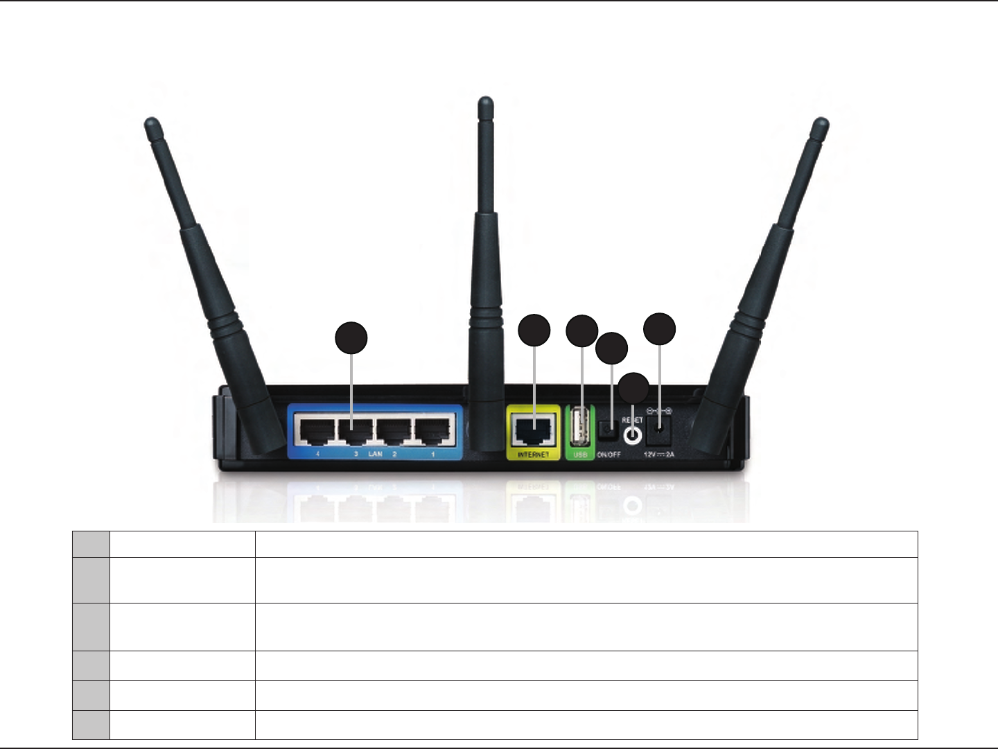
Connections
1LAN Ports (1-4) Connect 10/100/1000 Ethernet devices such as computers, switches, and NAS.
2Internet Port The auto MDI/MDIX Internet port is the connection for the Ethernet cable to the cable or DSL
modem.
3USB Port Connect a USB 1.1 or 2.0 ash drive to congure the wireless settings using WCN and
SharePort.
4Reset Button Pressing the Reset button restores the router to its original factory default settings.
5Power Button Press the power button to power on and o.
6Power Receptor Receptor for the supplied power adapter.
1234
5
6
6D-Link DIR-835 User Manual
Section 1 - Product Overview
Hardware Overview
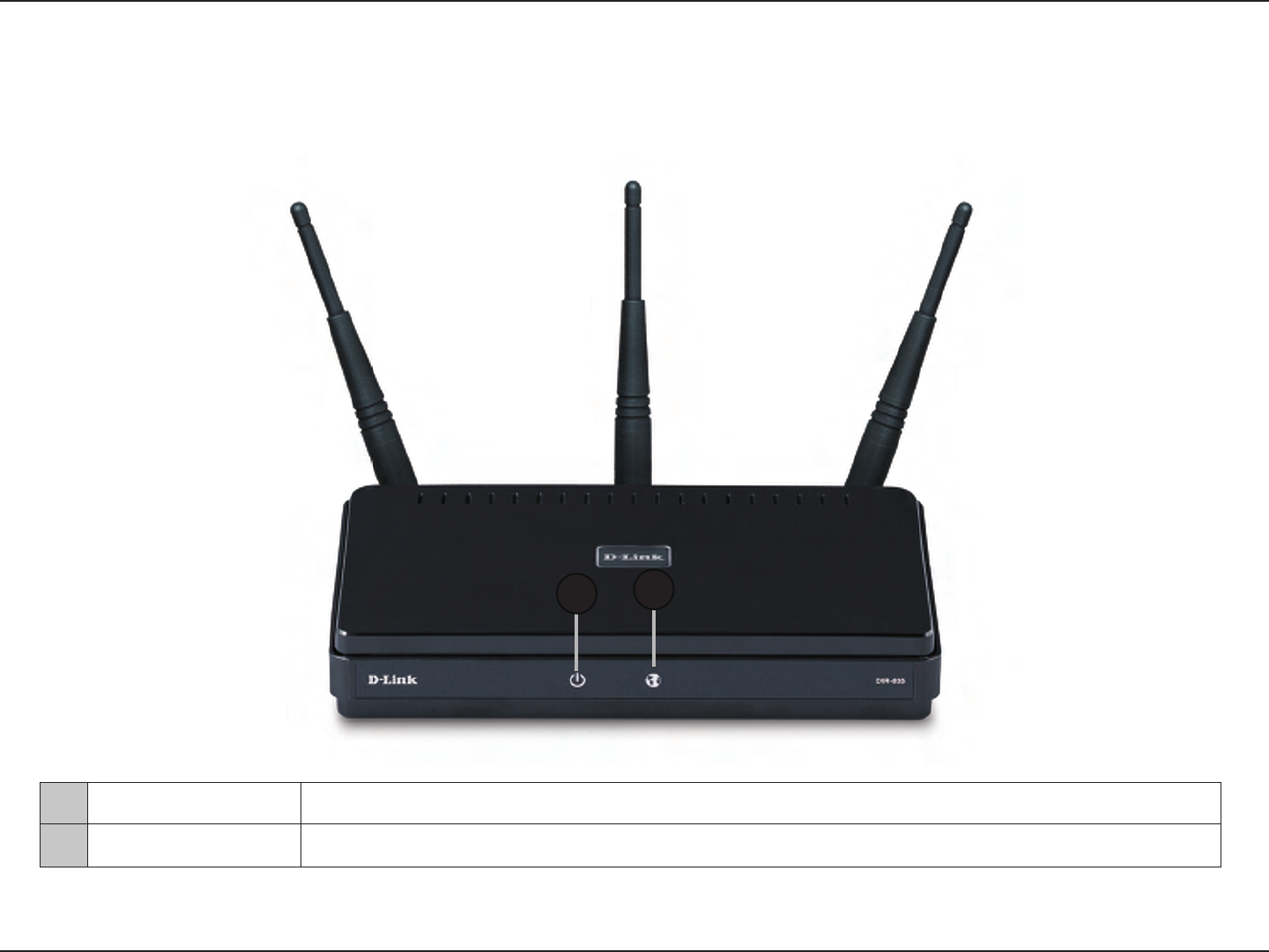
LEDs
1Power LED A solid green light indicates a proper connection to the power supply.
2Internet LED A solid green light indicates connection on the Internet port. This LED blinks during data transmission.
12

7D-Link DIR-835 User Manual
Section 2 - Installation
Before you Begin
Installation
This section will walk you through the installation process. Placement of the router is very important. Do not place the router
in an enclosed area such as a closet, cabinet, or in the attic or garage.
• Please congure the router with the computer that was last connected directly to your modem.
• You can only use the Ethernet port on your modem. If you were using the USB connection before using the
router, then you must turn o your modem, disconnect the USB cable and connect an Ethernet cable to the
Internet port on the router, and then turn the modem back on. In some cases, you may need to call your ISP to
change connection types (USB to Ethernet).
• If you have DSL and are connecting via PPPoE, make sure you disable or uninstall any PPPoE software such as
WinPoet, Broadjump, or Enternet 300 from your computer or you will not be able to connect to the Internet.
• When running the Setup Wizard from the D-Link CD, make sure the computer you are running the CD from
is connected to the Internet and online or the wizard will not work. If you have disconnected any hardware,
re-connect your computer back to the modem and make sure you are online.

8D-Link DIR-835 User Manual
Section 2 - Installation
Wireless Installation Considerations
The D-Link wireless router lets you access your network using a wireless connection from virtually anywhere within the
operating range of your wireless network. Keep in mind, however, that the number, thickness and location of walls, ceilings,
or other objects that the wireless signals must pass through, may limit the range. Typical ranges vary depending on the types
of materials and background RF (radio frequency) noise in your home or business. The key to maximizing wireless range is to
follow these basic guidelines:
1. Keep the number of walls and ceilings between the D-Link router and other network devices to a minimum - each
wall or ceiling can reduce your adapter’s range from 3-90 feet (1-30 meters.) Position your devices so that the number
of walls or ceilings is minimized.
2. Be aware of the direct line between network devices. A wall that is 1.5 feet thick (.5 meters), at a 45-degree angle
appears to be almost 3 feet (1 meter) thick. At a 2-degree angle it looks over 42 feet (14 meters) thick! Position
devices so that the signal will travel straight through a wall or ceiling (instead of at an angle) for better reception.
3. Building Materials make a dierence. A solid metal door or aluminum studs may have a negative eect on range.
Try to position access points, wireless routers, and computers so that the signal passes through drywall or open
doorways. Materials and objects such as glass, steel, metal, walls with insulation, water (sh tanks), mirrors, le
cabinets, brick, and concrete will degrade your wireless signal.
4. Keep your product away (at least 3-6 feet or 1-2 meters) from electrical devices or appliances that generate RF
noise.
5. If you are using 2.4GHz cordless phones or X-10 (wireless products such as ceiling fans, lights, and home security
systems), your wireless connection may degrade dramatically or drop completely. Make sure your 2.4GHz phone
base is as far away from your wireless devices as possible. The base transmits a signal even if the phone in not
in use.

9D-Link DIR-835 User Manual
Section 2 - Installation
If you are connecting the router to a cable/DSL/satellite modem, please follow the steps below:
1. Place the router in an open and central location. Do not plug the power adapter into the router.
2. Unplug the modem’s power adapter. Shut down your computer.
3. Unplug the Ethernet cable (that connects your computer to your modem) from your computer and place it into
the Internet port on the router.
4. Plug an Ethernet cable into one of the four LAN ports on the router. Plug the other end into the Ethernet port
on your computer.
5. Plug in your modem. Wait for the modem to boot (about 30 seconds).
6. Plug the power adapter to the router and connect to an outlet or power strip. Wait about 30 seconds for the
router to boot.
7. Turn on your computer.
8. Refer to page 13 to congure your router.
Connect to Cable/DSL/Satellite Modem

10D-Link DIR-835 User Manual
Section 2 - Installation
If you are connecting the D-Link router to another router to use as a wireless access point and/or switch, you will have to do
the following before connecting the router to your network:
• Disable UPnP™
• Disable DHCP
• Change the LAN IP address to an available address on your network. The LAN ports on the router cannot accept
a DHCP address from your other router.
To connect to another router, please follow the steps below:
1. Plug the power into the router. Connect one of your computers to the router (LAN port) using an Ethernet cable. Make sure
your IP address on the computer is 192.168.0.xxx (where xxx is between 2 and 254). Please see the Networking Basics
section for more information. If you need to change the settings, write down your existing settings before making any
changes. In most cases, your computer should be set to receive an IP address automatically in which case you will not have
to do anything to your computer.
2. Open a web browser and enter http://192.168.0.1 and press Enter. When the login window appears, set the user name to
Admin and leave the password box empty. Click Log In to continue.
3. Click on Advanced and then click Advanced Network. Uncheck the Enable UPnP checkbox. Click Save Settings to
continue.
4. Click Setup and then click Network Settings. Uncheck the Enable DHCP Server checkbox. Click Save Settings to
continue.
5. Under Router Settings, enter an available IP address and the subnet mask of your network. Click Save Settings to save your
settings. Use this new IP address to access the conguration utility of the router in the future. Close the browser and change
your computer’s IP settings back to the original values as in Step 1.
Connect to Another Router

11D-Link DIR-835 User Manual
Section 2 - Installation
6. Disconnect the Ethernet cable from the router and reconnect your computer to your network.
7. Connect an Ethernet cable in one of the LAN ports of the router and connect it to your other router. Do not plug anything
into the Internet (WAN) port of the D-Link router.
8. You may now use the other 3 LAN ports to connect other Ethernet devices and computers. To congure your wireless network,
open a web browser and enter the IP address you assigned to the router. Refer to the Conguration and Wireless Security
sections for more information on setting up your wireless network.
12D-Link DIR-835 User Manual
Section 2 - Installation
The DIR-835 includes a Quick Router Setup Wizard CD. Follow the simple steps below to run the Setup Wizard to guide you
quickly through the installation process.
Insert the Quick Router Setup Wizard CD in the CD-ROM drive. The step-by-step instructions that follow are shown in Windows®
XP. The steps and screens are similar for the other Windows operating systems.
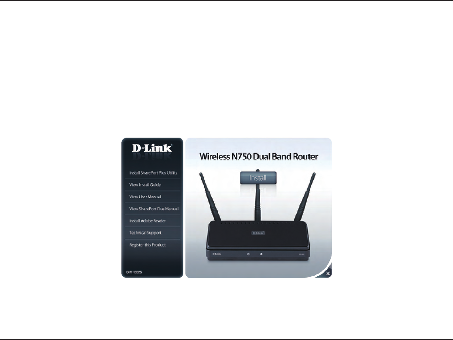
If the CD Autorun function does not automatically start on your computer, go to Start > Run. In the run box type “D:\autorun.exe”
(where D: represents the drive letter of your CD-ROM drive).
When the autorun screen appears, click Install.
Getting Started
Note: It is recommended to write down the SSID and Security Key, followed by the login password on the provided CD holder.
13D-Link DIR-835 User Manual
Section 3 - Conguration
Conguration
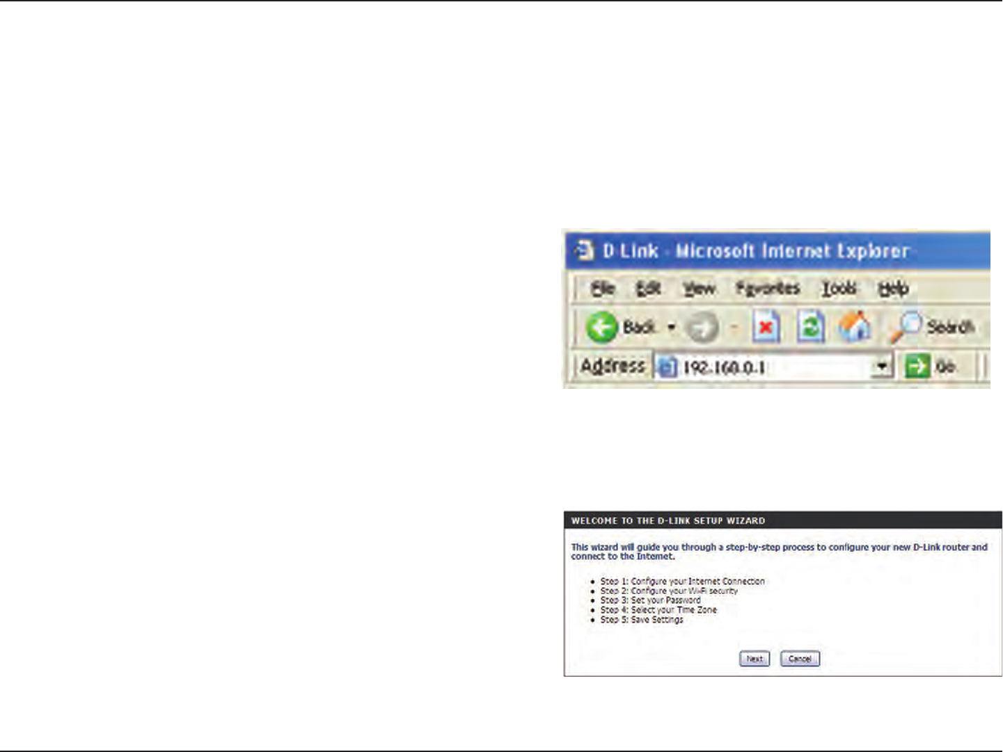
This section will show you how to congure your new D-Link wireless router using the web-based conguration utility.
To access the conguration utility, open a web-browser such
as Internet Explorer and enter the IP address of the router
(192.168.0.1).
You may also connect using the NetBIOS name in the address bar
(http://dlinkrouter).
This wizard is designed to guide you through a step-by
step process to congure your new D-Link router and
connect to the Internet.
Click Next to continue.
Quick Setup Wizard
14D-Link DIR-835 User Manual
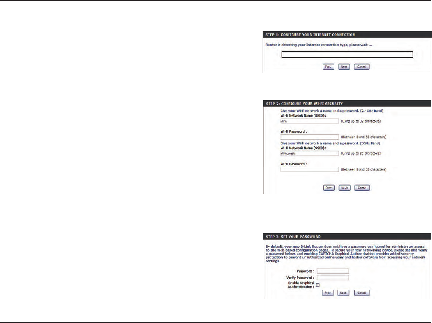
Section 3 - Conguration
In order to secure your new networking device, please enter
a password and click Next.
Please wait while your router detects your internet
connection type.
Please give your network a name using up to 32 characters.
Click Next to continue.
15D-Link DIR-835 User Manual
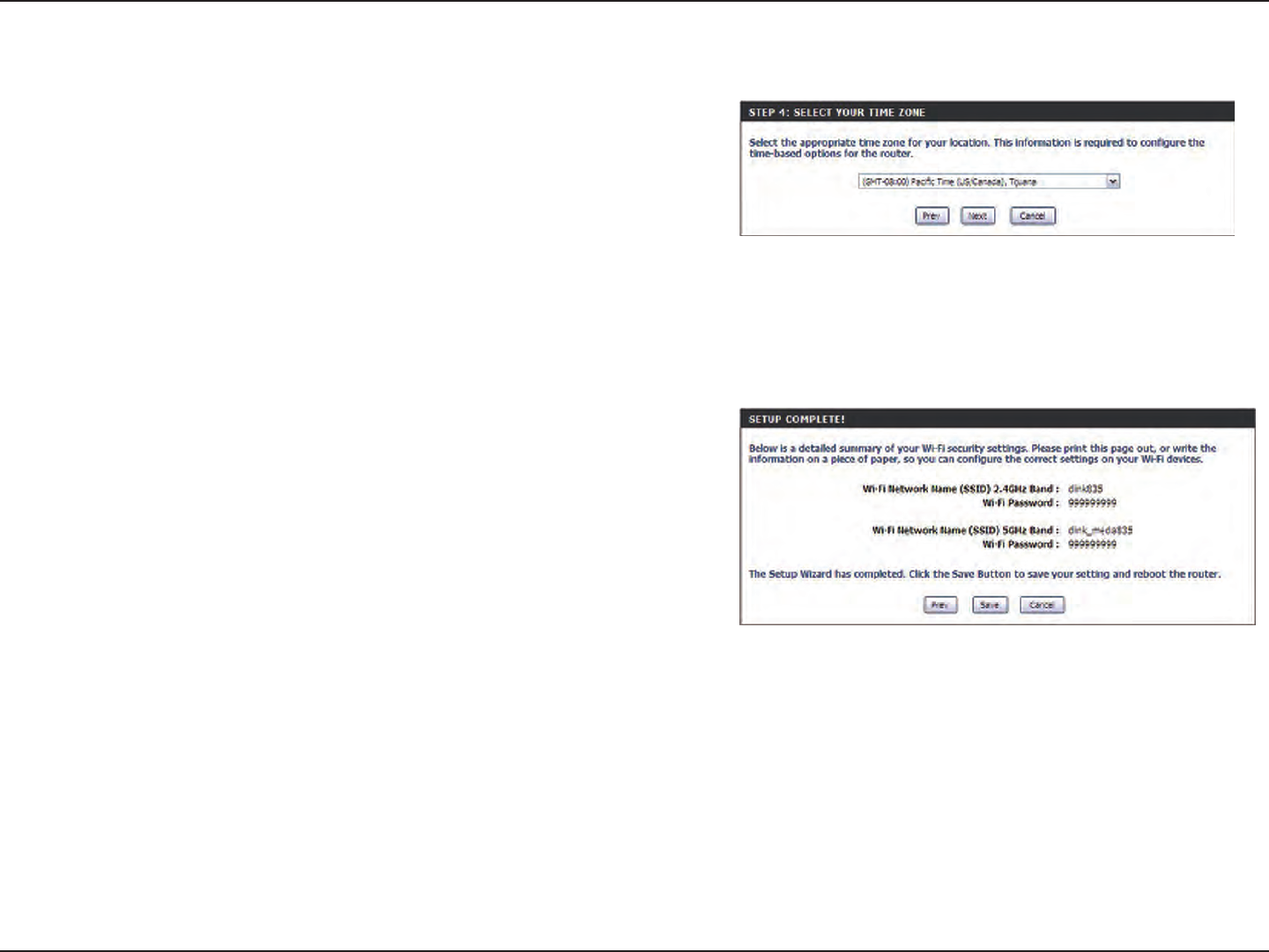
Section 3 - Conguration
Once this screen appears, your setup is complete. Click Save
& Connect to reboot the router.
Select your time zone from the drop-down menu and click
Next to continue.
16D-Link DIR-835 User Manual
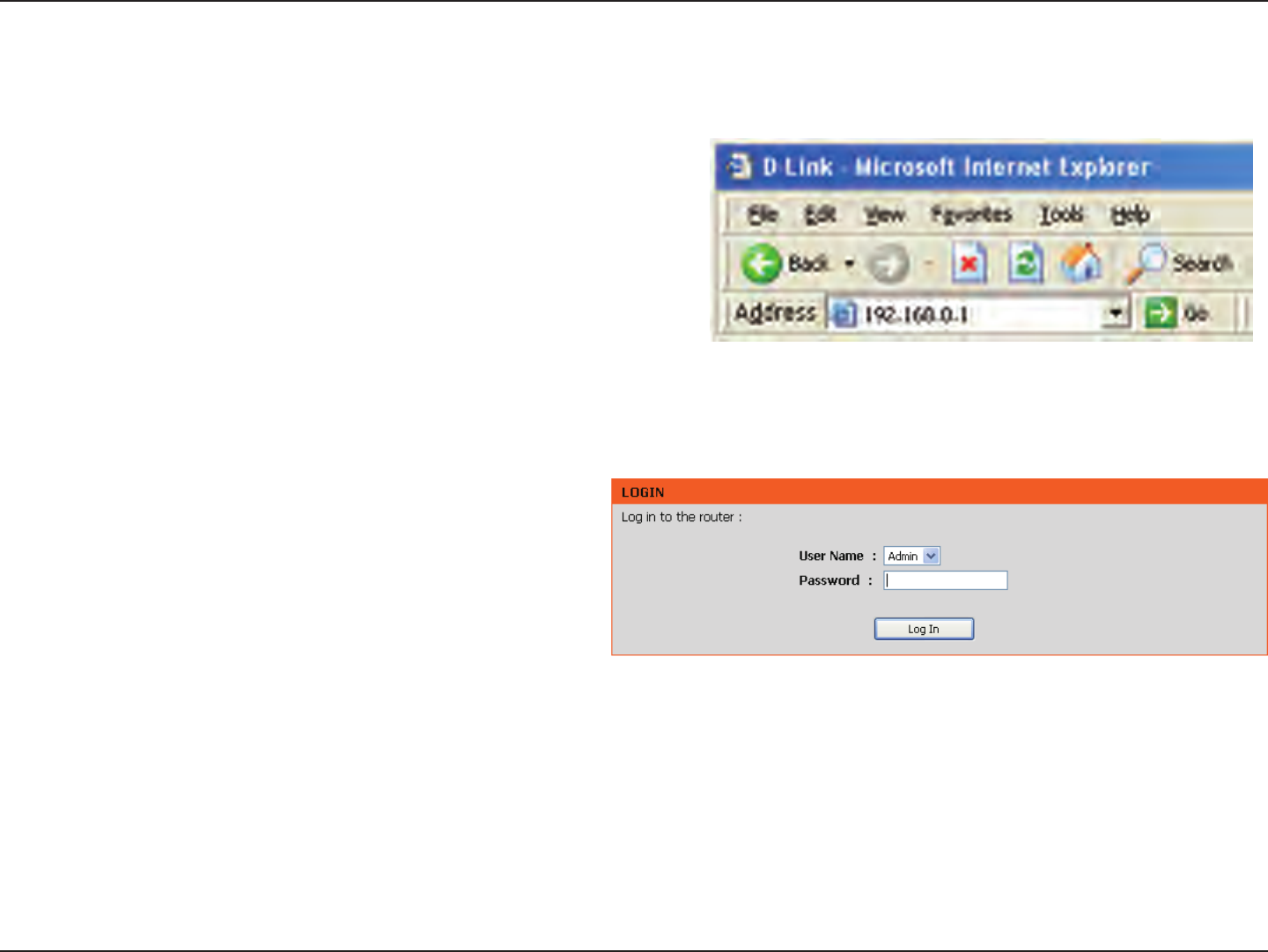
Section 3 - Conguration
Web-based Conguration Utility
To access the conguration utility, open a web-browser such
as Internet Explorer and enter the IP address of the router
(192.168.0.1).
If you selected Cancel Setup on the Quick Setup Wizard
page, you will be directed to this screen.
Select Admin from the drop-down menu and then enter
your password. Leave the password blank by default.
If you get a Page Cannot be Displayed error, please refer
to the Troubleshooting section for assistance.
17D-Link DIR-835 User Manual
Section 3 - Conguration
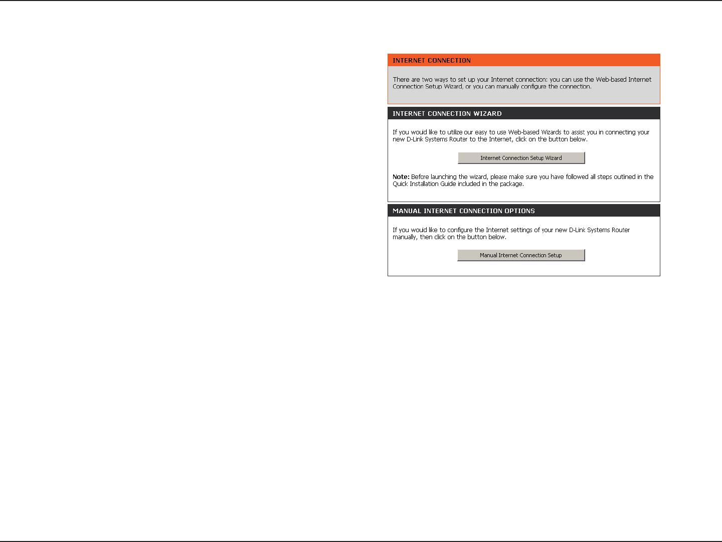
Internet Connection Setup
Select the Internet Connection you would like to use.
Click Manual Internet Connection Setup to congure your
connection manually and continue on pg 18.
If you want to congure your router to connect to the Internet
using the wizard, click Internet Connection Setup Wizard.
You will be directed to the Quick Setup Wizard section on
pg 13.
18D-Link DIR-835 User Manual
Section 3 - Conguration
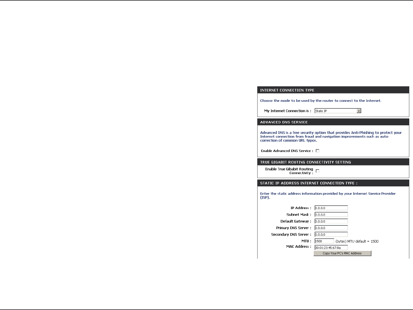
Static IP
Enter the IP address assigned by your ISP.
Enter the Subnet Mask assigned by your ISP.
Enter the Gateway assigned by your ISP.
The DNS server information will be supplied by your ISP (Internet Service
Provider.)
Maximum Transmission Unit - you may need to change the MTU for
optimal performance with your specic ISP. 1500 is the default MTU.
The default MAC Address is set to the Internet port’s physical interface
MAC address on the Broadband Router. It is not recommended that you
change the default MAC address unless required by your ISP. You can use
the Clone Your PC’s MAC Address button to replace the Internet port’s
MAC address with the MAC address of your Ethernet card.
IP Address:
Subnet Mask:
Default Gateway:
DNS Servers:
MTU:
MAC Address:
Internet Setup
Static (assigned by ISP)
Select Static IP Address if all the Internet port’s IP information is provided to you by your ISP. You will need to enter in the IP address, subnet mask,
gateway address, and DNS address(es) provided to you by your ISP. Each IP address entered in the elds must be in the appropriate IP form, which
are four octets separated by a dot (x.x.x.x). The Router will not accept the IP address if it is not in this format.
19D-Link DIR-835 User Manual
Section 3 - Conguration
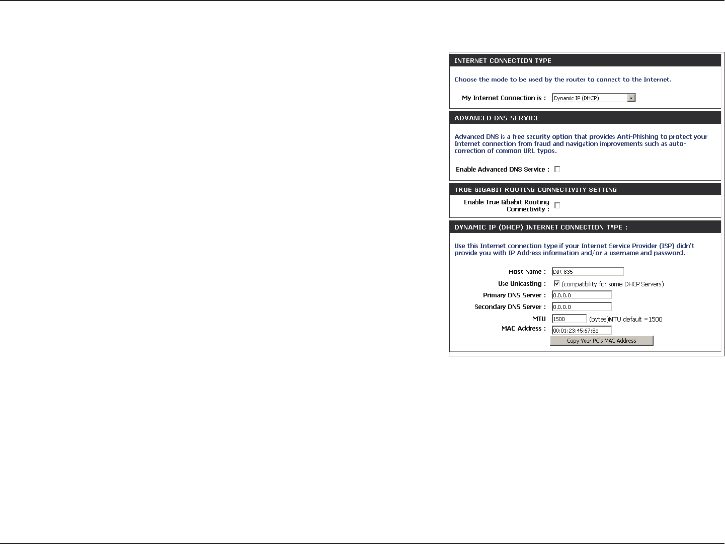
Select Dynamic IP (DHCP) to obtain IP Address information automatically from your
ISP. Select this option if your ISP does not give you any IP numbers to use. This option
is commonly used for cable modem services such as Comcast and Cox.
Advanced Domain Name System (DNS) services enhances your Internet performance by
getting you the information and web pages you are looking for faster and more reliably.
In addition, it improves your overall Internet experience by correcting many common typo
mistakes automatically, taking you where you intended to go and saving you valuable time.
Disclaimer: D-Link makes no warranty as to the availability, reliability, functionality and
operation of the Advanced DNS service or its features.
The Host Name is optional but may be required by some ISPs. Leave blank if you are
not sure.
Check the box if you are having problems obtaining an IP address from your ISP.
Enter the Primary and secondary DNS server IP addresses assigned by your ISP. These
addresses are usually obtained automatically from your ISP. Leave at 0.0.0.0 if you did
not specically receive these from your ISP.
Maximum Transmission Unit - you may need to change the MTU for optimal performance
with your specic ISP. 1500 is the default MTU.
The default MAC Address is set to the Internet port’s physical interface MAC address on
the Broadband Router. It is not recommended that you change the default MAC address unless required by your ISP. You can use the Clone Your PC’s MAC
Address button to replace the Internet port’s MAC address with the MAC address of your Ethernet card.
My Internet
Connection:
Enable
Advanced
DNS Service:
Host Name:
MAC Address:
Dynamic (Cable)
Primary/
Secondary DNS
Server:
MTU:
Use Unicasting:
20D-Link DIR-835 User Manual
Section 3 - Conguration
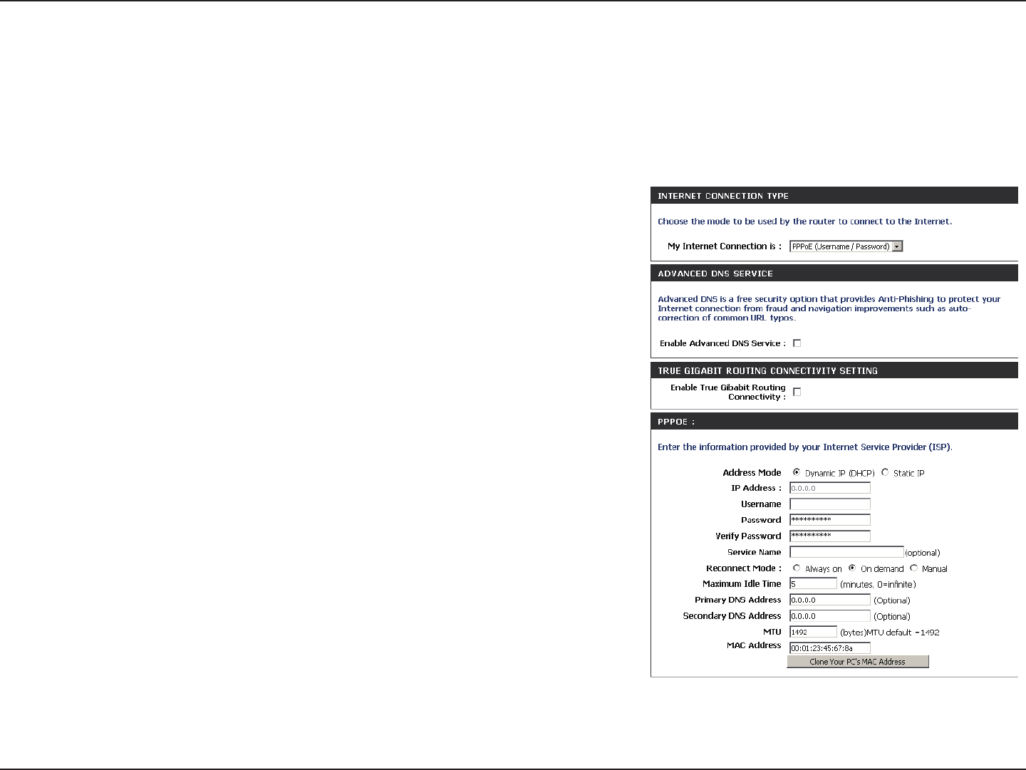
Select PPPoE(Username/Password) from the drop-down menu.
Select Static IP if your ISP assigned you the IP address, subnet mask,
gateway, and DNS server addresses. In most cases, select Dynamic.
Enter the IP address (Static PPPoE only).
Enter your PPPoE user name.
Enter your PPPoE password and then retype the password in the next box.
Enter the ISP Service Name (optional).
Select either Always-on, On-Demand, or Manual.
Enter a maximum idle time during which the Internet connection is
maintained during inactivity. To disable this feature, enable Auto-reconnect.
Enter the Primary and Secondary DNS Server Addresses (Static PPPoE only).
Maximum Transmission Unit - you may need to change the MTU for optimal
performance with your specic ISP. 1492 is the default MTU.
The default MAC Address is set to the Internet port’s physical interface MAC
address on the Broadband Router. It is not recommended that you change the default MAC address unless required by your ISP.
You can use the Clone Your PC’s MAC Address button to replace the Internet port’s MAC address with the MAC address of your
Ethernet card.
My Internet
Connection:
Address Mode:
IP Address:
User Name:
Password:
Service Name:
Reconnect
Mode:
Maximum Idle
Time:
DNS Addresses:
MTU:
MAC Address:
Internet Setup
PPPoE (DSL)
Choose PPPoE (Point to Point Protocol over Ethernet) if your ISP uses a PPPoE connection. Your ISP will provide you with a
username and password. This option is typically used for DSL services. Make sure to remove your PPPoE software from your
computer. The software is no longer needed and will not work through a router.
21D-Link DIR-835 User Manual
Section 3 - Conguration
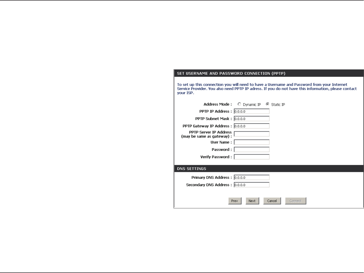
Select Static if your ISP assigned you the IP address,
subnet mask, gateway, and DNS server addresses. In
most cases, select Dynamic.
Enter the IP address (Static PPTP only).
Enter the Primary and Secondary DNS Server
Addresses (Static PPTP only).
Enter the Gateway IP Address provided by your ISP.
Enter the Server IP provided by your ISP (optional).
Enter your PPTP username.
Enter your PPTP password and then retype the
password in the next box.
Select either Always-on, On-Demand, or Manual.
Enter a maximum idle time during which the Internet connection is maintained during inactivity. To disable this feature, enable
Auto-reconnect.
The DNS server information will be supplied by your ISP (Internet Service Provider.)
Address Mode:
PPTP IP Address:
PPTP Subnet
Mask:
PPTP Gateway:
PPTP Server IP:
Internet Setup
PPTP
Choose PPTP (Point-to-Point-Tunneling Protocol ) if your ISP uses a PPTP connection. Your ISP will provide you with a username
and password. This option is typically used for DSL services.
Username:
Password:
Reconnect
Mode:
Maximum Idle
Time:
DNS Servers:

22D-Link DIR-835 User Manual
Section 3 - Conguration
Maximum Transmission Unit - you may need to change the MTU for optimal performance with your specic ISP. 1400 is the default
MTU.
The default MAC Address is set to the Internet port’s physical interface MAC address on the Broadband Router. It is not recommended
that you change the default MAC address unless required by your ISP. You can use the Clone Your PC’s MAC Address button to
replace the Internet port’s MAC address with the MAC address of your Ethernet card.
MTU:
MAC Address:
23D-Link DIR-835 User Manual
Section 3 - Conguration
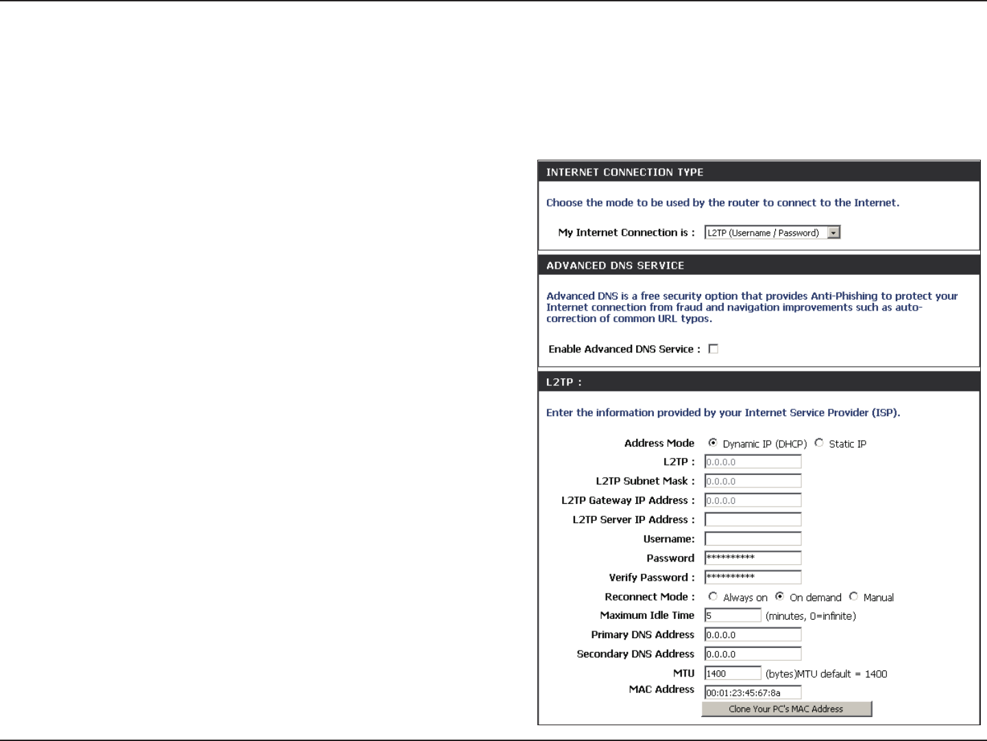
Select Static if your ISP assigned you the IP address, subnet
mask, gateway, and DNS server addresses. In most cases,
select Dynamic.
Enter the L2TP IP address supplied by your ISP (Static only).
Enter the Subnet Mask supplied by your ISP (Static only).
Enter the Gateway IP Address provided by your ISP.
Enter the Server IP provided by your ISP (optional).
Enter your L2TP username.
Enter your L2TP password and then retype the password in
the next box.
Select either Always-on, On-Demand, or Manual.
Enter a maximum idle time during which the Internet
connection is maintained during inactivity. To disable this
feature, enable Auto-reconnect.
Enter the Primary and Secondary DNS Server Addresses (Static
L2TP only).
Address Mode:
L2TP IP Address:
L2TP Subnet
Mask:
L2TP Gateway:
L2TP Server IP:
Username:
Password:
Reconnect
Mode:
Maximum Idle
Time:
DNS Servers:
Internet Setup
L2TP
Choose L2TP (Layer 2 Tunneling Protocol) if your ISP uses a L2TP connection. Your ISP will provide you with a username and
password. This option is typically used for DSL services.

24D-Link DIR-835 User Manual
Section 3 - Conguration
MTU:
Clone MAC
Address:
Maximum Transmission Unit - you may need to change the MTU for optimal performance with your specic ISP. 1400 is the default
MTU.
The default MAC Address is set to the Internet port’s physical interface MAC address on the Broadband Router. It is not recommended
that you change the default MAC address unless required by your ISP. You can use the Clone Your PC’s MAC Address button to
replace the Internet port’s MAC address with the MAC address of your Ethernet card.
25D-Link DIR-835 User Manual
Section 3 - Conguration
Internet Setup
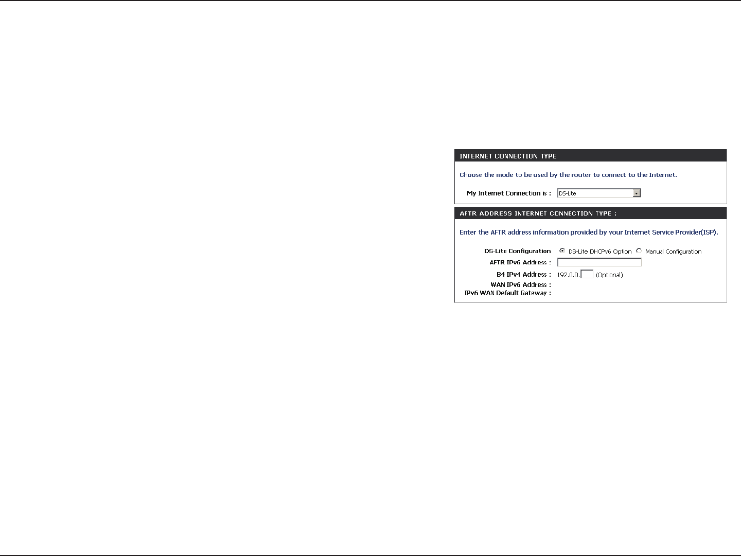
DS-Lite
Another Internet Connection type is DS-Lite.
DS-Lite
Conguration:
Select the DS-Lite DHCPv6 option to let the router allocate the
AFTR IPv6 address automatically. Select the Manual Conguration
to enter the AFTR IPv6 address in manually.
AFTR IPv6
Address:
After selecting the Manual Conguration option above, enter the
AFTR IPv6 address used here.
B4 IPv4 Address: Enter the B4 IPv4 address value used here.
WAN IPv6
Address:
Once connected, the WAN IPv6 address will be displayed here.
IPv6 WAN
Default Gateway
Once connected, the IPv6 WAN Default Gateway address will be
displayed here.
DS-Lite is an IPv6 connection type. After selecting DS-Lite, the following parameters will be available for conguration:
26D-Link DIR-835 User Manual
Section 3 - Conguration
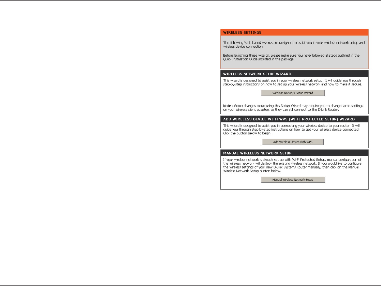
Wireless Settings
If you want to congure the wireless settings on your router using
the wizard, click Wireless Security Setup Wizard and refer to
page 94.
Click Add Wireless Device with WPS if you want to add a wireless
device using Wi-Fi Protected Setup (WPS) and refer to page 96.
If you want to manually congure the wireless settings on your
router click Manual Wireless Network Setup and refer to the
next page.
27D-Link DIR-835 User Manual
Section 3 - Conguration
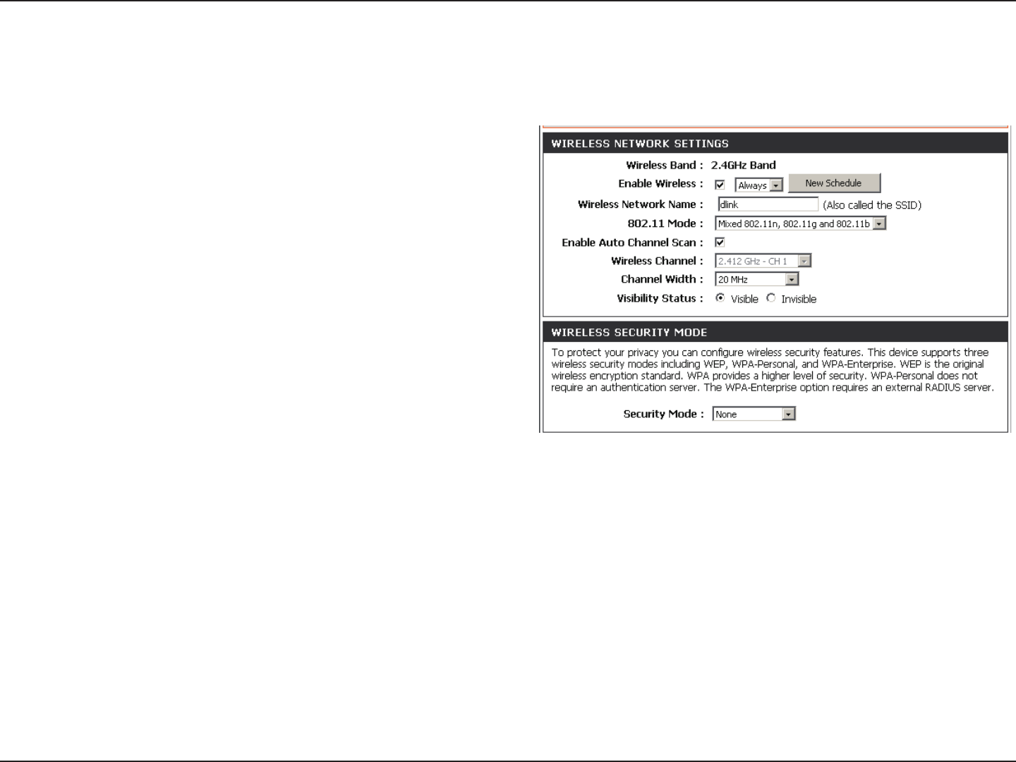
Check the box to enable the wireless function. If you do
not want to use wireless, uncheck the box to disable all the
wireless functions.
Select the time frame that you would like your wireless
network enabled. The schedule may be set to Always. Any
schedule you create will be available in the drop-down menu.
Click Add New to create a new schedule.
Service Set Identier (SSID) is the name of your wireless
network. Create a name using up to 32 characters. The SSID
is case-sensitive.
Select one of the following:
802.11g Only - Select if all of your wireless clients are 802.11g.
Mixed 802.11n and 802.11g - Select if you are using both
802.11n and 802.11g wireless clients.
802.11n Only - Select only if all of your wireless clients are 802.11n.
The Auto Channel Scan setting can be selected to allow the DIR-835 to choose the channel with the least amount of interference.
Indicates the channel setting for the DIR-835. By default the channel is set to 6. The Channel can be changed to t the channel
setting for an existing wireless network or to customize the wireless network. If you enable Auto Channel Scan, this option will
be greyed out.
Select the transmit rate. It is strongly suggested to select Best (Auto) for best performance.
Select the Channel Width:
Auto20/40 - This is the default setting. Select if you are using both 802.11n and non-802.11n wireless devices.
Enable Wireless:
Schedule:
Wireless Network
Name:
802.11 Mode:
Enable Auto
Channel Scan:
Wireless Channel:
Transmission Rate:
Manual Wireless Settings
802.11n/g (2.4GHz)

28D-Link DIR-835 User Manual
Section 3 - Conguration
20MHz - Select if you are not using any 802.11n wireless clients.
40MHz - Select if you are using 802.11n wireless clients only.
Select Invisible if you do not want the SSID of your wireless network to be broadcasted by the DIR-835. If Invisible is selected, the
SSID of the DIR-835 will not be seen by Site Survey utilities so your wireless clients will have to know the SSID of your DIR-835 in
order to connect to it.
Refer to page 93 for more information regarding wireless security.
Channel Width:
Visibility Status:
Wireless Security:
29D-Link DIR-835 User Manual
Section 3 - Conguration
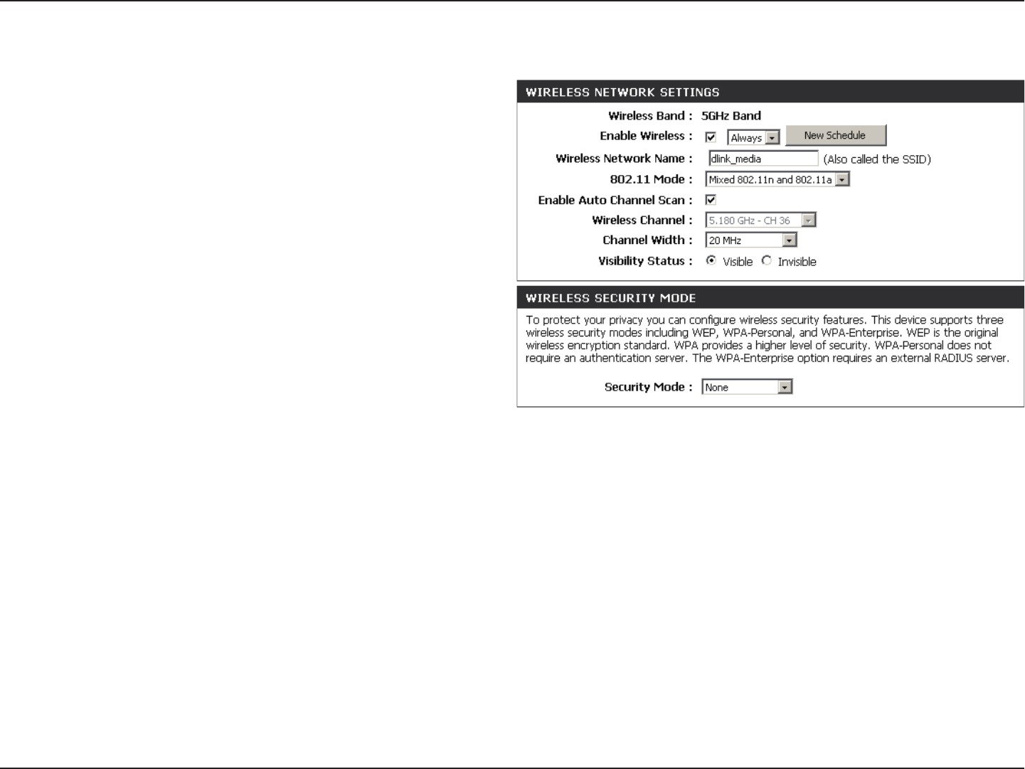
802.11n/a (5GHz)
Check the box to enable the wireless function. If you do
not want to use wireless, uncheck the box to disable all
the wireless functions.
Select the time frame that you would like your wireless
network enabled. The schedule may be set to Always. Any
schedule you create will be available in the drop-down
menu. Click Add New to create a new schedule.
Service Set Identier (SSID) is the name of your wireless
network. Create a name using up to 32 characters. The
SSID is case-sensitive.
Select one of the following:
802.11a Only - Select if all of your wireless clients are
802.11a.
Mixed 802.11n and 802.11a - Select if you are using
both 802.11n and 802.11a wireless clients.
802.11n Only - Select only if all of your wireless clients are 802.11n.
The Auto Channel Scan setting can be selected to allow the DIR-835 to choose the channel with the least amount of interference.
Indicates the channel setting for the DIR-835. By default the channel is set to 6. The Channel can be changed to t the channel
setting for an existing wireless network or to customize the wireless network. If you enable Auto Channel Scan, this option will
be greyed out.
Select the transmit rate. It is strongly suggested to select Best (Auto) for best performance.
Enable Wireless:
Schedule:
Wireless
Network Name:
802.11 Mode:
Enable Auto
Channel Scan:
Wireless
Channel:
Transmission
Rate:

30D-Link DIR-835 User Manual
Section 3 - Conguration
Select the Channel Width:
Auto20/40 - This is the default setting. Select if you are using both 802.11n and non-802.11n wireless devices.
20MHz - Select if you are not using any 802.11n wireless clients.
40MHz - Select if you are using 802.11n wireless clients only.
Select Invisible if you do not want the SSID of your wireless network to be broadcasted by the DIR-835. If Invisible is selected, the
SSID of the DIR-835 will not be seen by Site Survey utilities so your wireless clients will have to know the SSID of your DIR-835 in
order to connect to it.
Refer to page 93 for more information regarding wireless security.
Channel Width:
Visibility Status:
Wireless Security:
31D-Link DIR-835 User Manual
Section 3 - Conguration
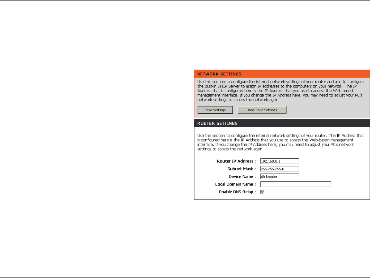
This section will allow you to change the local network settings of the router and to congure the DHCP settings.
Network Settings
Enter the IP address of the router. The default IP address
is 192.168.0.1.
If you change the IP address, once you click Save Settings,
you will need to enter the new IP address in your browser
to get back into the conguration utility.
Enter the Subnet Mask. The default subnet mask is
255.255.255.0.
Enter the Domain name (Optional).
Uncheck the box to transfer the DNS server information
from your ISP to your computers. If checked, your
computers will use the router for a DNS server.
Router IP Address:
Subnet Mask:
Local Domain:
Enable DNS Relay:
Router Settings
32D-Link DIR-835 User Manual
Section 3 - Conguration
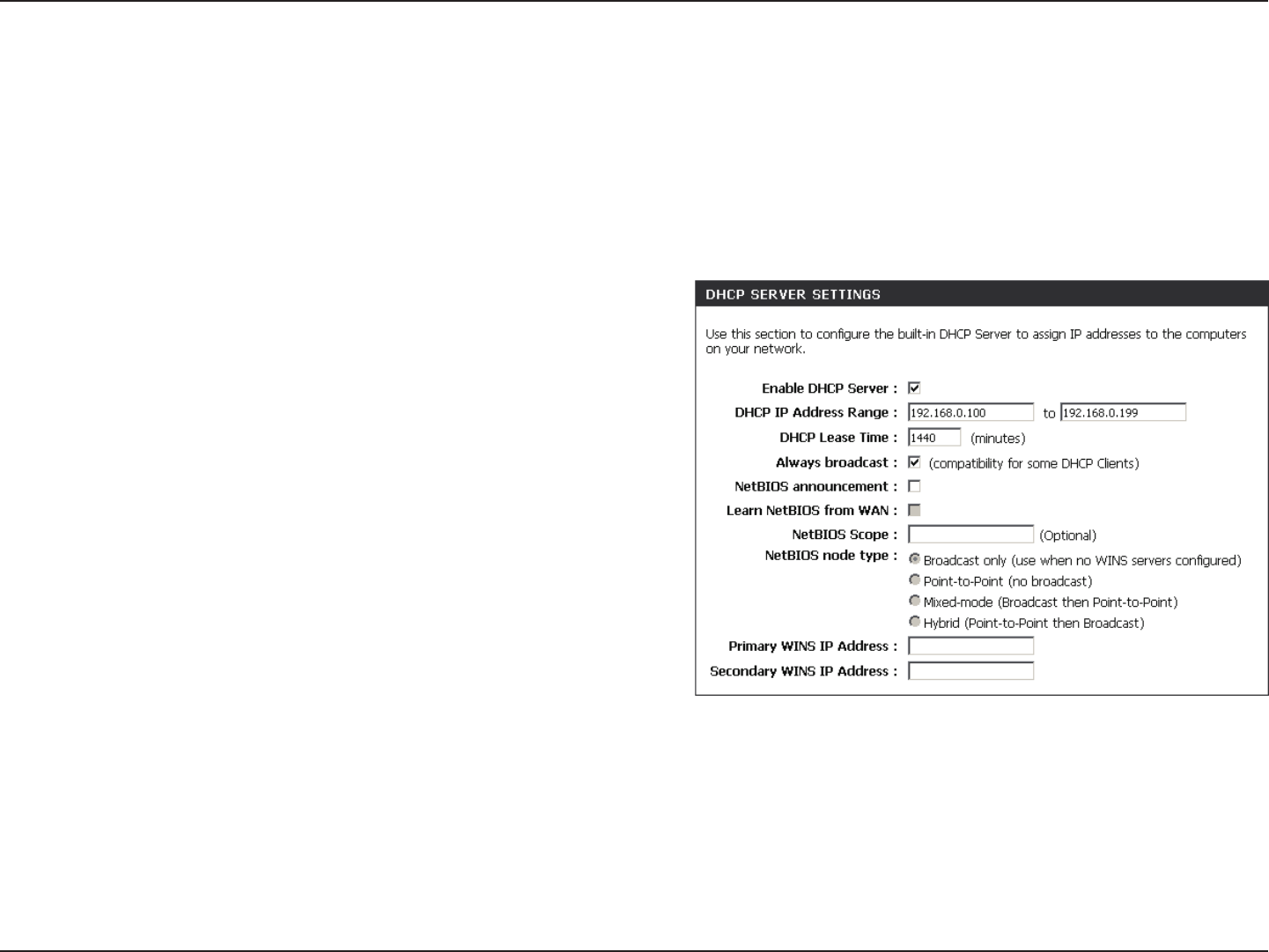
DHCP Server Settings
DHCP stands for Dynamic Host Control Protocol. The DIR-835 has a built-in DHCP server. The DHCP Server will automatically
assign an IP address to the computers on the LAN/private network. Be sure to set your computers to be DHCP clients by setting
their TCP/IP settings to “Obtain an IP Address Automatically.” When you turn your computers on, they will automatically load
the proper TCP/IP settings provided by the DIR-835. The DHCP Server will automatically allocate an unused IP address from
the IP address pool to the requesting computer. You must specify the starting and ending address of the IP address pool.
Check this box to enable the DHCP server on your router.
Uncheck to disable this function.
Enter the starting and ending IP addresses for the DHCP server’s
IP assignment.
Note: If you statically (manually) assign IP addresses to your
computers or devices, make sure the IP addresses are outside of
this range or you may have an IP conict.
The length of time for the IP address lease. Enter the Lease time
in minutes.
Enable this feature to broadcast your networks DHCP server to
LAN/WLAN clients.
NetBIOS allows LAN hosts to discover all other computers within
the network, enable this feature to allow the DHCP Server to
oer NetBIOS conguration settings.
Enable this feature to allow WINS information to be learned from the WAN side, disable to allow manual conguration.
This feature allows the conguration of a NetBIOS ‘domain’ name under which network hosts operates. This setting has no eect if
the ‘Learn NetBIOS information from WAN’ is activated.
Enable DHCP
Server:
DHCP IP Address
Range:
DHCP Lease Time:
Always
Broadcast:
NetBIOS
Announcement:
Learn NetBIOS
from WAN:
NetBIOS Scope:

33D-Link DIR-835 User Manual
Section 3 - Conguration
NetBIOS Node:
WINS IP
Address:
Select the dierent type of NetBIOS node; Broadcast only, Point-to-Point, Mixed-mode, and Hybrid.
Enter your WINS IP address.
34D-Link DIR-835 User Manual
Section 3 - Conguration
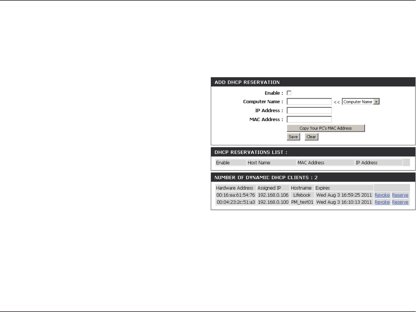
DHCP Reservation
If you want a computer or device to always have the same IP address assigned, you can create a DHCP reservation. The router
will assign the IP address only to that computer or device.
Note: This IP address must be within the DHCP IP Address Range.
Check this box to enable the reservation.
Enter the computer name or select from the drop
down menu and click <<.
Enter the IP address you want to assign to the
computer or device. This IP Address must be within
the DHCP IP Address Range.
Enter the MAC address of the computer or device.
If you want to assign an IP address to the computer
you are currently on, click this button to populate the
elds.
Click Save to save your entry. You must click Save
Settings at the top to activate your reservations.
Enable:
Computer
Name:
IP Address:
MAC Address:
Copy Your PC’s
MAC Address:
Save:
35D-Link DIR-835 User Manual
Section 3 - Conguration
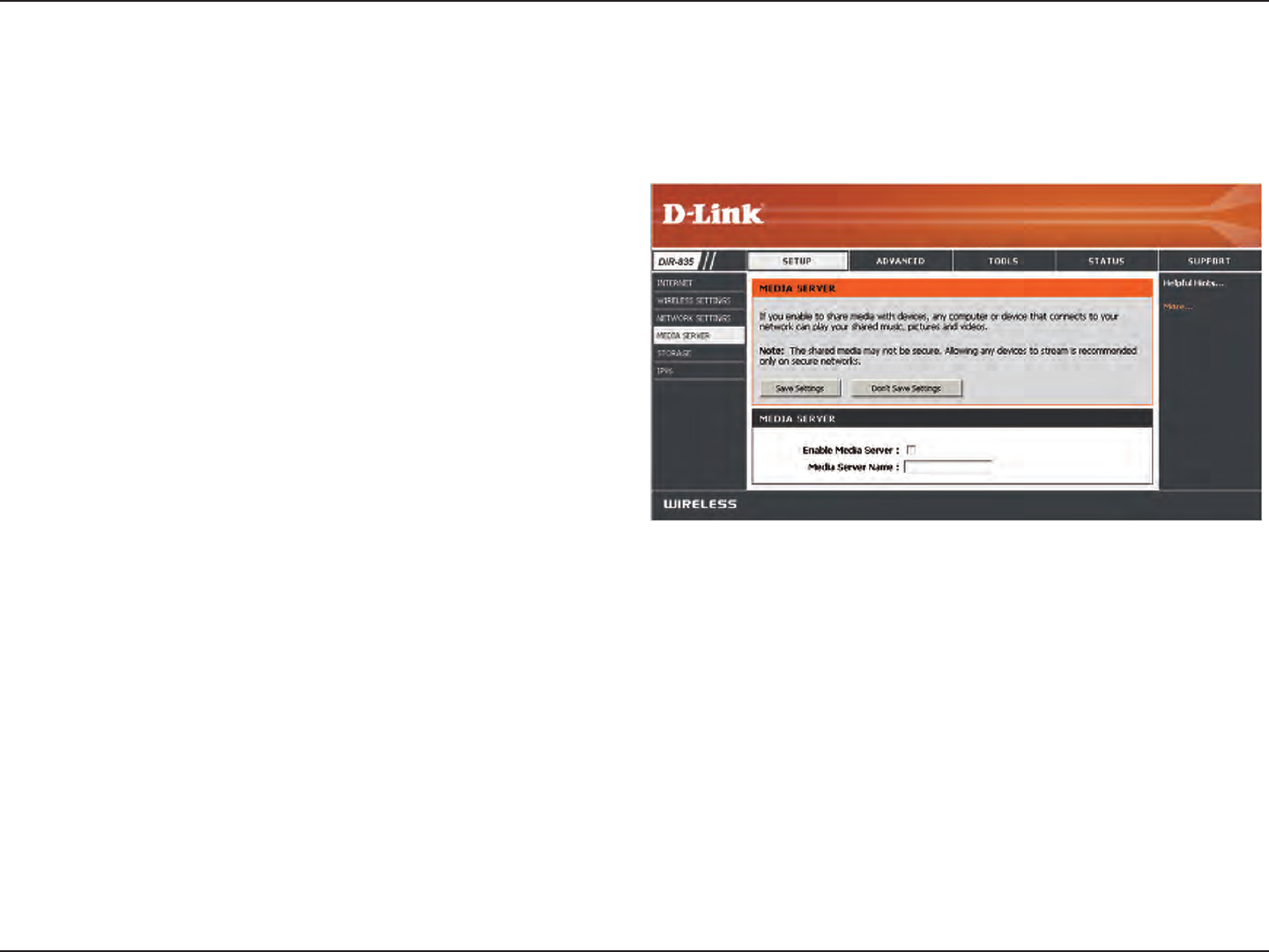
Media Server
This feature allows you to share music, pictures and videos with any devices connected to your network.
Check this box to enable the media server feature.
Enter the media server’s name.
Click Save to save your entry. You must click Save
Settings at the top to activate your reservations.
Enable Media
Server:
Computer
Name:
36D-Link DIR-835 User Manual
Section 3 - Conguration
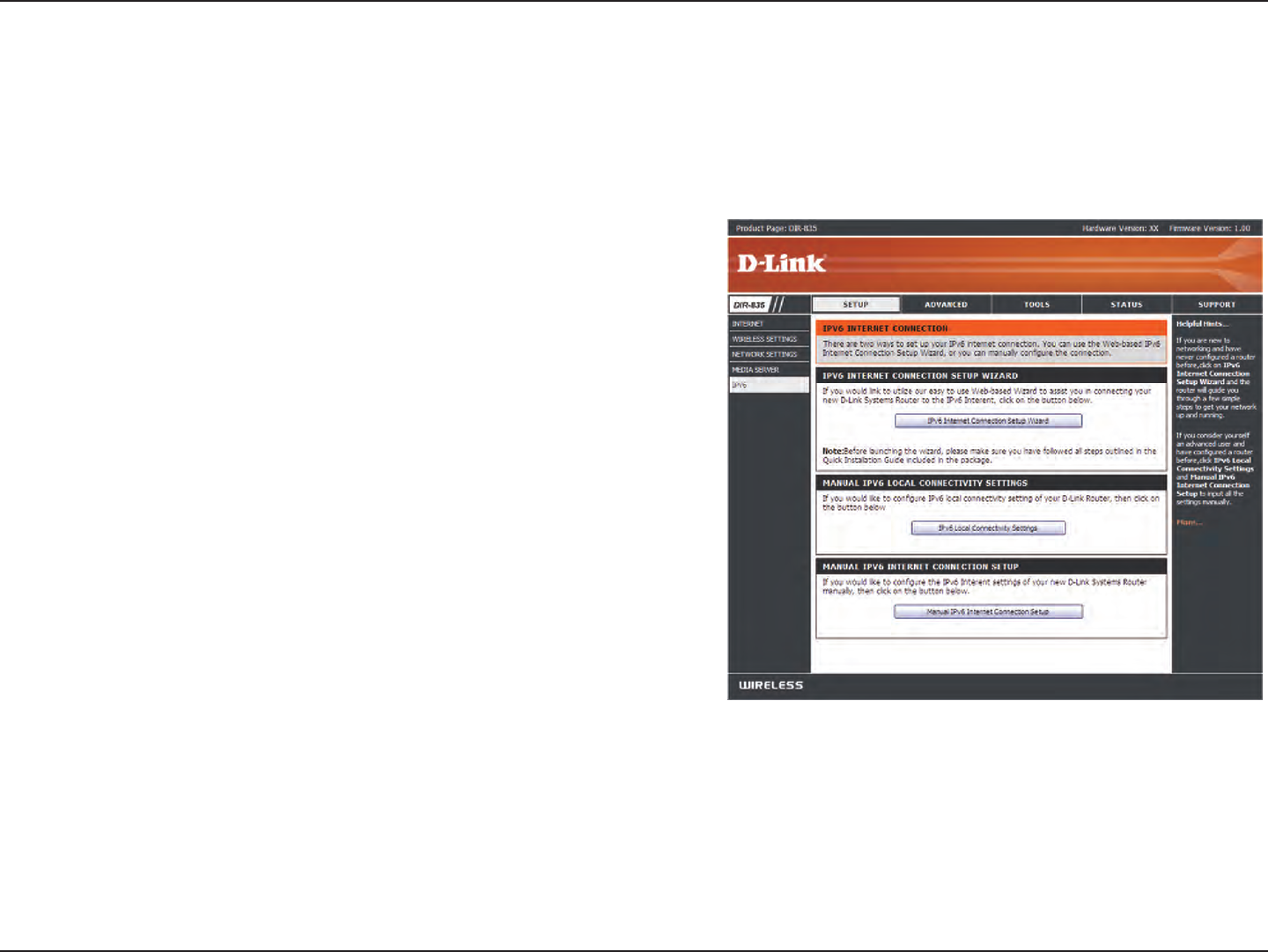
IPv6
On this page, the user can congure the IPv6 Connection type. There are two ways to set up the IPv6 Internet connection. You
can use the Webbased IPv6 Internet Connection Setup Wizard, or you can manually congure the connection.
IPv6 Internet Connection Setup Wizard
For the beginner user that has not congured a router before, click
on the IPv6 Internet Connection Setup Wizard button and the router
will guide you through a few simple steps to get your network up and
running.
Manual IPv6 Internet Connection Option
For the advanced user that has congured a router before, click on
the Manual IPv6 Internet Connection Setup button to input all the
settings manually.
37D-Link DIR-835 User Manual
Section 3 - Conguration
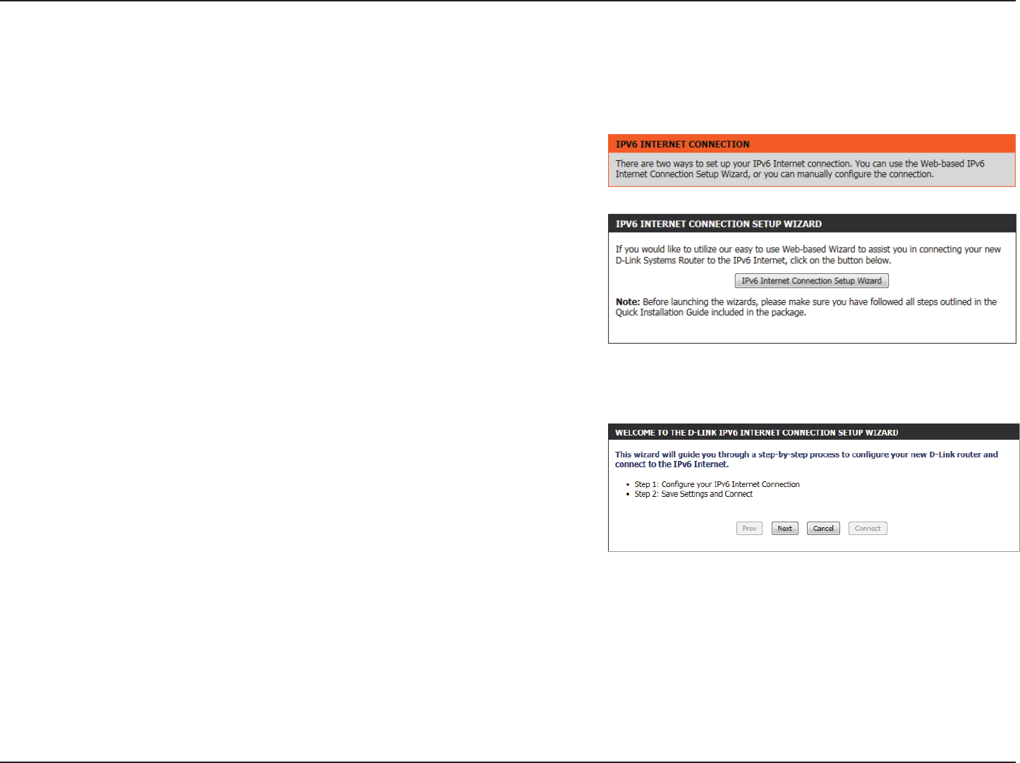
IPv6 Internet Connection Setup Wizard
On this page, the user can congure the IPv6 Connection type. There are two ways to set up the IPv6 Internet connection. You can use the Web-
based IPv6 Internet Connection Setup Wizard, or you can manually congure the connection.
Click the IPv6 Internet Connection Setup Wizard button and the router will guide
you through a few simple steps to get your network up and running.
The wizard will guide you through a step-by-step process to congure your new
D-Link router and connect to the IPv6 Internet.
Click Next to continue to the next page. Click Cancel to discard the changes
made and return to the main page.
38D-Link DIR-835 User Manual
Section 3 - Conguration
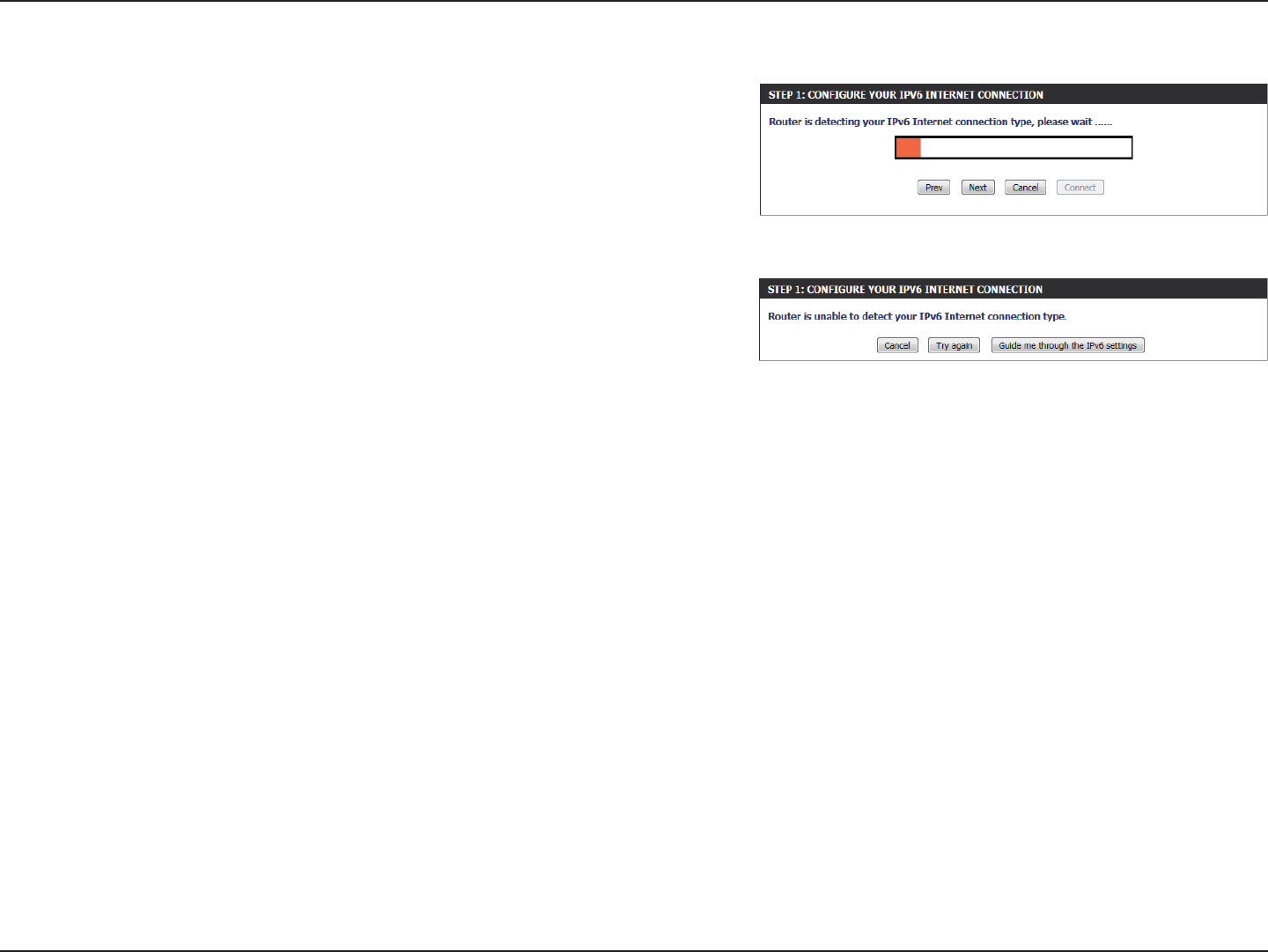
The router will try to detect whether its possible to obtain the IPv6 Internet
connection type automatically. If this succeeds then the user will be guided
through the input of the appropriate parameters for the connection type found.
However, if the automatic detection fails, the user will be prompt to either Try
again or to click on the Guide me through the IPv6 settings button to initiate the
manual continual of the wizard.
39D-Link DIR-835 User Manual
Section 3 - Conguration
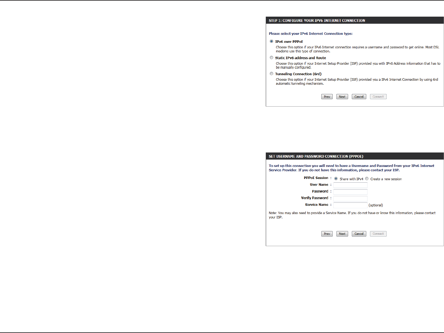
There are several connection types to choose from. If you are unsure of your
connection method, please contact your IPv6 Internet Service Provider.
Note: If using the PPPoE option, you will need to ensure that any PPPoE client
software on your computers has been removed or disabled. The 3 options available
on this page are IPv6 over PPPoE, Static IPv6 address and Route, and Tunneling
Connection.
Choose the required IPv6 Internet Connection type and click on the Next button
to continue. Click on the Prev button to return to the previous page. Click on the
Cancel button to discard all the changes made and return to the main page.
IPv6 over PPPoE
After selecting the IPv6 over PPPoE option, the user will be able to congure the
IPv6 Internet connection that requires a username and password to get online.
Most DSL modems use this type of connection.
The following parameters will be available for conguration:
PPPoE Session: Select the PPPoE Session value used here. This option will
state that this connection shares it’s information with the
already congured IPv6 PPPoE connection, or the user can
create a new PPPoE connection here.
User Name: Enter the PPPoE username used here. If you do not know
your user name, please contact your ISP.
Password: Enter the PPPoE password used here. If you do not know
your password, please contact your ISP.
Verify Password: Re-enter the PPPoE password used here.
Service Name: Enter the service name for this connection here. This option
is optional.
Click on the Next button to continue. Click on the Prev button to return to the previous page.
Click on the Cancel button to discard all the changes made and return to the main page.
40D-Link DIR-835 User Manual
Section 3 - Conguration
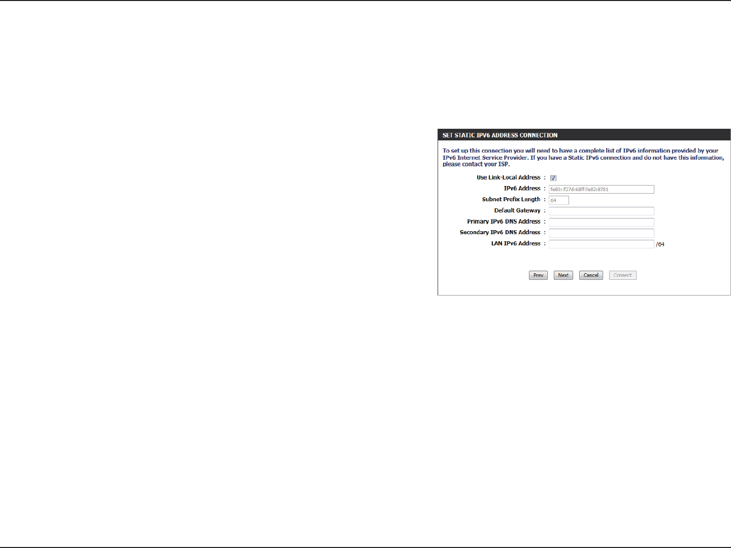
Static IPv6 Address Connection
This mode is used when your ISP provides you with a set IPv6 addresses that does not change. The IPv6 information is manually entered in your
IPv6 conguration settings. You must enter the IPv6 address, Subnet Prex Length, Default Gateway, Primary DNS Server, and Secondary DNS
Server. Your ISP provides you with all this information.
Click on the Next button to continue. Click on the Prev button to return to the previous page.
Click on the Cancel button to discard all the changes made and return to the main page.
Use Link-Local
Address:
IPv6 Address:
Subnet Prex
Length:
Default Gateway:
Primary IPv6 DNS
Address:
Secondary IPv6 DNS
Address:
LAN IPv6 Address:
The Link-local address is used by nodes and routers when communicating
with neighboring nodes on the same link. This mode enables IPv6-
capable devices to communicate with each other on the LAN side.
Enter the WAN IPv6 address for the router here.
Enter the WAN subnet prex length value used here.
Enter the WAN default gateway IPv6 address used here.
Enter the WAN primary DNS Server address used here.
Enter the WAN secondary DNS Server address used here.
These are the settings of the LAN (Local Area Network) IPv6 interface for the router. The router’s LAN IPv6 Address conguration is based on the IPv6
Address and Subnet assigned by your ISP. (A subnet with prex /64 is supported in LAN.)
41D-Link DIR-835 User Manual
Section 3 - Conguration
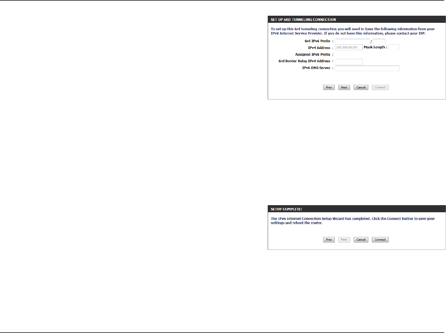
Tunneling Connection (6rd)
After selecting the Tunneling Connection (6rd) option, the user can
congure the IPv6 6rd connection settings.
The following parameters will be available for conguration:
6rd IPv6 Prex: Enter the 6rd IPv6 address and prex value used
here.
IPv4 Address: Enter the IPv4 address used here.
Mask Length: Enter the IPv4 mask length used here.
Assigned IPv6
Prex:
Displays the IPv6 assigned prex value here.
6rd Border Relay
IPv4 Address:
Enter the 6rd border relay IPv4 address used here.
IPv6 DNS Server: Enter the primary DNS Server address used here.
Click on the Next button to continue. Click on the Prev button to return to the previous page.
Click on the Cancel button to discard all the changes made and return to the main page.
The IPv6 Internet Connection Setup Wizard was completed.
Click on the Connect button to continue. Click on the Prev button to return to the
previous page. Click on the Cancel button to discard all the changes made and return
to the main page.
42D-Link DIR-835 User Manual
Section 3 - Conguration
IPv6 Manual Setup
There are several connection types to choose from: Auto Detection, Static IPv6, Autoconguration (SLAAC/DHCPv6), PPPoE,
IPv6 in IPv4 Tunnel, 6to4, 6rd, and Link-local. If you are unsure of your connection method, please contact your IPv6 Internet
Service Provider.
Note: If using the PPPoE option, you will need to ensure that any PPPoE client software on your computers has been removed
or disabled.
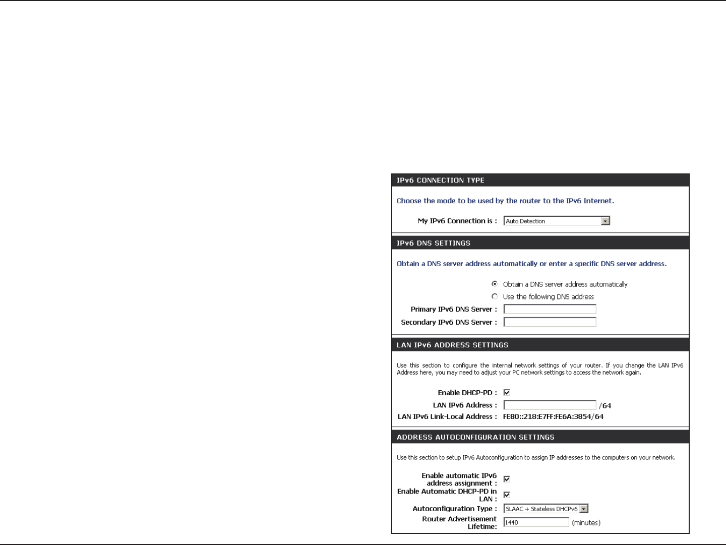
Auto Detection
Select Auto Detection to have the router detect and
automatically congure your IPv6 setting from your ISP.
43D-Link DIR-835 User Manual
Section 3 - Conguration
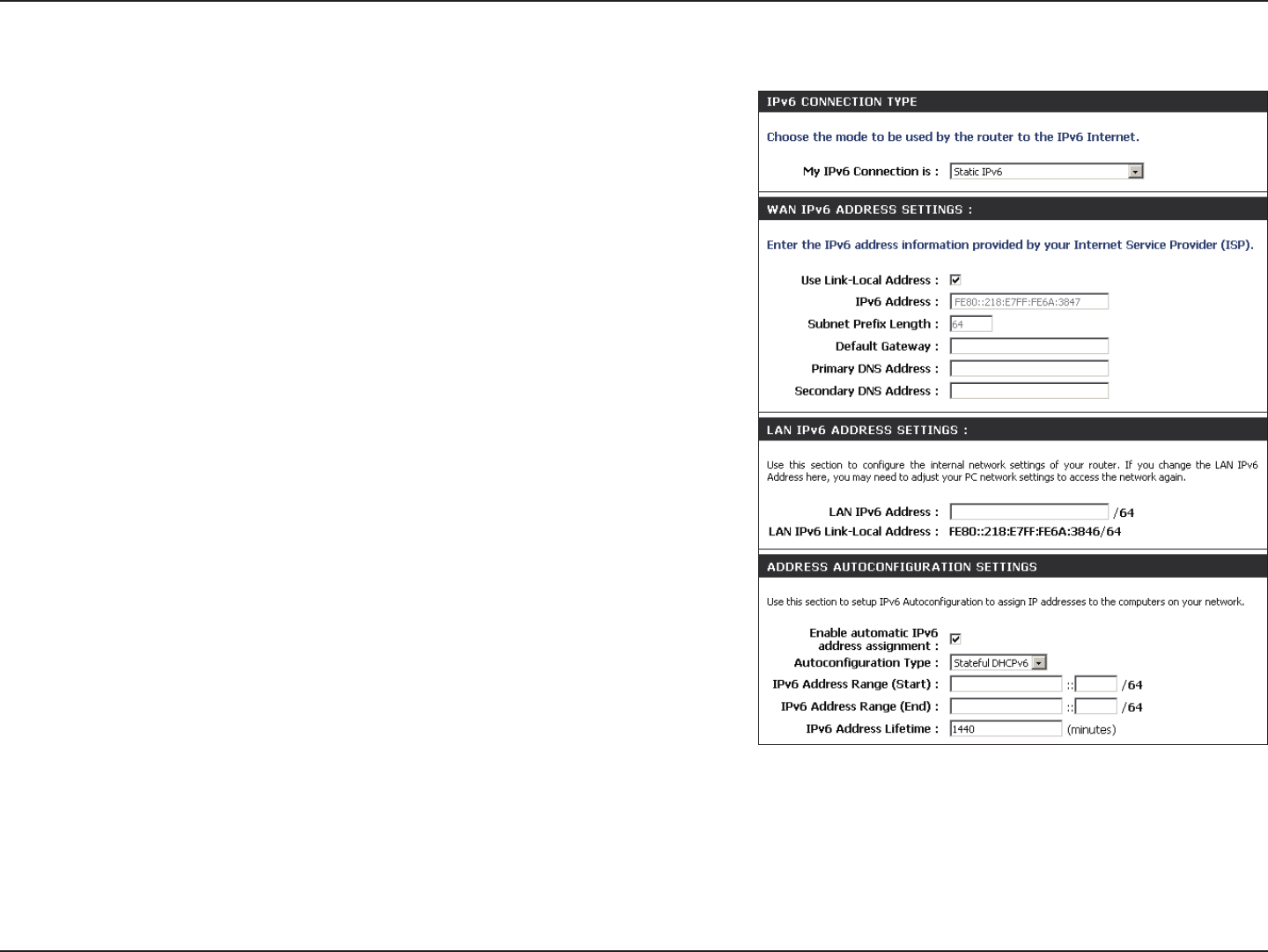
Static IPv6
Select Static IPv6 from the drop-down menu.
Enter the address settings supplied by your Internet provider
(ISP).
Enter the LAN (local) IPv6 address for the router.
Displays the Router’s LAN Link-Local Address.
Check to enable the Autoconguration feature.
Select Stateful (DHCPv6), SLAAC + RDNSS or SLAAC +
Stateless DHCPv6.
Enter the start IPv6 Address for the DHCPv6 range for your local
computers.
Enter the end IPv6 Address for the DHCPv6 range for your local
computers.
Enter the IPv6 Address Lifetime (in minutes).
My IPv6 Connection:
WAN IPv6 Address
Settings:
LAN IPv6 Address:
LAN Link-Local Address:
Enable
Autoconguration:
Autoconguration Type:
IPv6 Address Range
Start:
IPv6 Address Range
End:
IPv6 Address Lifetime:
44D-Link DIR-835 User Manual
Section 3 - Conguration
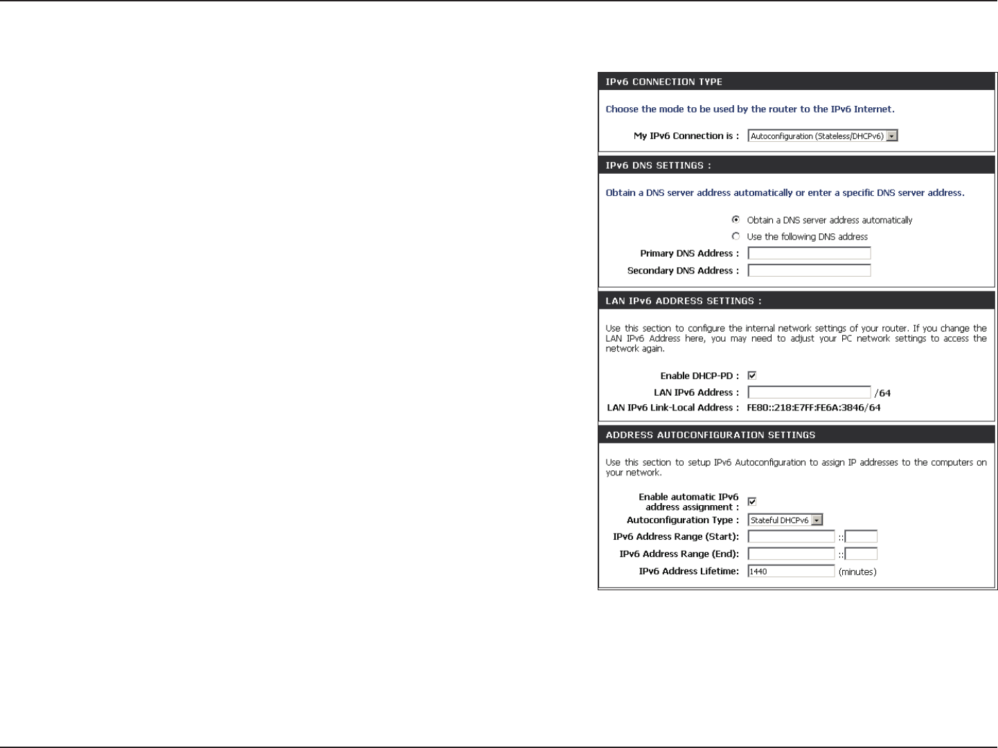
Autoconguration
Select Autoconguration(Stateless/DHCPv6) from the drop-
down menu.
Select either Obtain DNS server address automatically or Use
the following DNS Address.
Enter the primary and secondary DNS server addresses.
Enter the LAN (local) IPv6 address for the router.
Displays the Router’s LAN Link-Local Address.
Check to enable the Autoconguration feature.
Select Stateful (DHCPv6), SLAAC + RDNSS or SLAAC + Stateless
DHCPv6.
Enter the start IPv6 Address for the DHCPv6 range for your local
computers.
Enter the end IPv6 Address for the DHCPv6 range for your local
computers.
Enter the IPv6 Address Lifetime (in minutes).
My IPv6 Connection:
IPv6 DNS Settings:
Primary/Secondary DNS
Address:
LAN IPv6 Address:
LAN Link-Local Address:
Enable
Autoconguration:
Autoconguration Type:
IPv6 Address Range
Start:
IPv6 Address Range
End:
IPv6 Address Lifetime:
45D-Link DIR-835 User Manual
Section 3 - Conguration
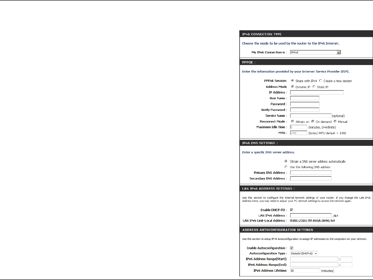
PPPoE
Select PPPoE from the drop-down menu.
Enter the PPPoE account settings supplied by your Internet provider
(ISP).
Select Static if your ISP assigned you the IP address, subnet mask,
gateway, and DNS server addresses. In most cases, select Dynamic.
Enter the IP address (Static PPPoE only).
Enter your PPPoE user name.
Enter your PPPoE password and then retype the password in the next
box.
Enter the ISP Service Name (optional).
Select either Always-on, On-Demand, or Manual.
Enter a maximum idle time during which the Internet connection
is maintained during inactivity. To disable this feature, enable Auto-
reconnect.
Maximum Transmission Unit - you may need to change the MTU for
optimal performance with your specic ISP. 1492 is the default MTU.
Select either Obtain DNS server address automatically or Use the
following DNS Address.
Enter the primary and secondary DNS server addresses.
Enter the LAN (local) IPv6 address for the router.
Displays the Router’s LAN Link-Local Address.
Check to enable the Autoconguration feature.
My IPv6 Connection:
PPPoE:
Address Mode:
IP Address:
User Name:
Password:
Service Name:
Reconnection Mode:
Maximum Idle Time:
MTU:
IPv6 DNS Settings:
Primary/Secondary DNS
Address:
LAN IPv6 Address:
LAN Link-Local Address:
Enable
Autoconguration:

46D-Link DIR-835 User Manual
Section 3 - Conguration
Autoconguration Type:
IPv6 Address Range Start:
IPv6 Address Range End:
IPv6 Address Lifetime:
Select Stateful (DHCPv6), SLAAC + RDNSS or SLAAC + Stateless DHCPv6.
Enter the start IPv6 Address for the DHCPv6 range for your local computers.
Enter the end IPv6 Address for the DHCPv6 range for your local computers.
Enter the IPv6 Address Lifetime (in minutes).
47D-Link DIR-835 User Manual
Section 3 - Conguration
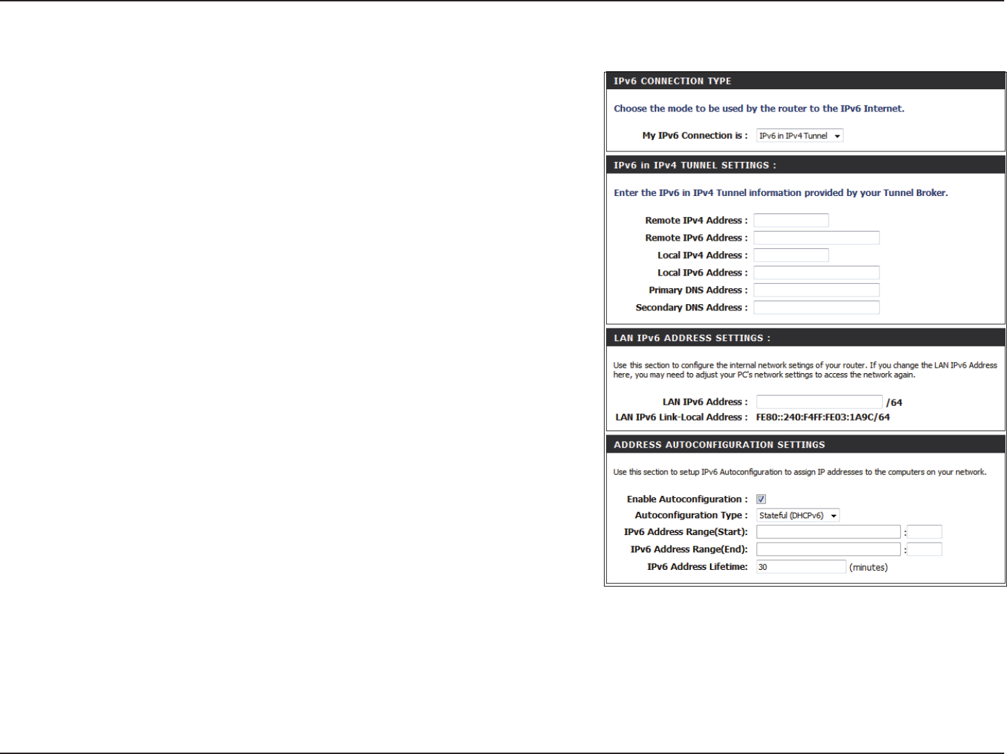
IPv6 in IPv4 Tunneling
Select IPv6 in IPv4 Tunnel from the drop-down menu.
Enter the settings supplied by your Internet provider (ISP).
Enter the LAN (local) IPv6 address for the router.
Displays the Router’s LAN Link-Local Address.
Check to enable the Autoconguration feature.
Select Stateful (DHCPv6), SLAAC + RDNSS or SLAAC + Stateless
DHCPv6.
Enter the start IPv6 Address for the DHCPv6 range for your local
computers.
Enter the end IPv6 Address for the DHCPv6 range for your local
computers.
Enter the Router Advertisement Lifetime (in minutes).
My IPv6
Connection:
IPv6 in IPv4 Tunnel
Settings:
LAN IPv6 Address:
LAN Link-Local
Address:
Enable
Autoconguration:
Autoconguration
Type:
IPv6 Address
Range Start:
IPv6 Address
Range End:
Pv6 Address
Lifetime:
48D-Link DIR-835 User Manual
Section 3 - Conguration
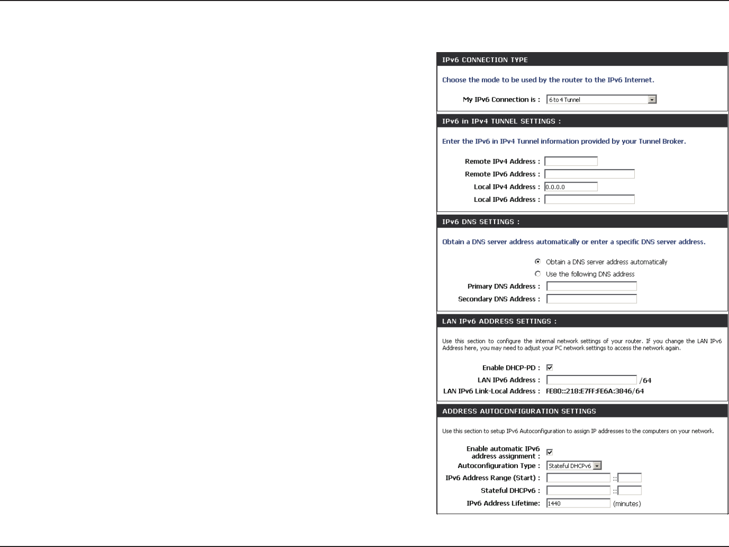
6 to 4 Tunneling
Select 6 to 4 from the drop-down menu.
Enter the IPv6 settings supplied by your Internet provider (ISP).
Enter the primary and secondary DNS server addresses.
Enter the LAN (local) IPv6 address for the router.
Displays the Router’s LAN Link-Local Address.
Check to enable the Autoconguration feature.
Select Stateful (DHCPv6), SLAAC + RDNSS or SLAAC + Stateless
DHCPv6.
Enter the start IPv6 Address for the DHCPv6 range for your local
computers.
Enter the end IPv6 Address for the DHCPv6 range for your local
computers.
Enter the IPv6 Address Lifetime (in minutes).
My IPv6 Connection:
6 to 4 Settings:
Primary/Secondary
DNS Address:
LAN IPv6 Address:
LAN Link-Local
Address:
Enable
Autoconguration:
Autoconguration
Type:
IPv6 Address Range
Start:
IPv6 Address Range
End:
IPv6 Address
Lifetime:
49D-Link DIR-835 User Manual
Section 3 - Conguration
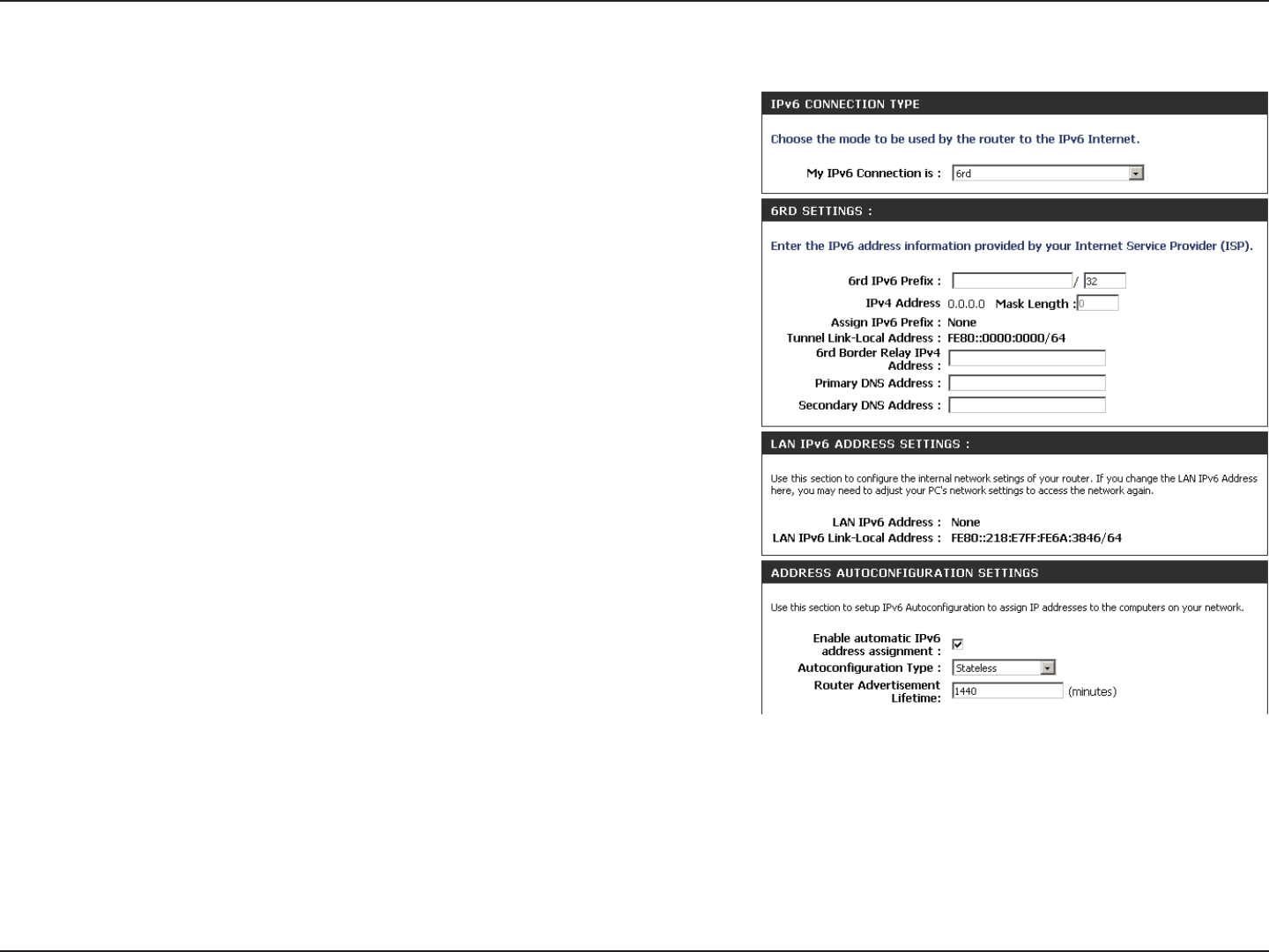
6rd
Select 6rd from the drop-down menu.
Enter the address settings supplied by your Internet provider
(ISP).
Enter the LAN (local) IPv6 address for the router.
Displays the Router’s LAN Link-Local Address.
Check to enable the Autoconguration feature.
Select Stateful (DHCPv6), SLAAC+RDNSS or SLAAC + Stateless
DHCPv6.
Enter the Router Advertisement Lifetime (in minutes).
My IPv6 Connection:
6RD Settings:
LAN IPv6 Address:
LAN Link-Local Address:
Enable
Autoconguration:
Autoconguration Type:
Router Advertisement
Lifetime:
50D-Link DIR-835 User Manual
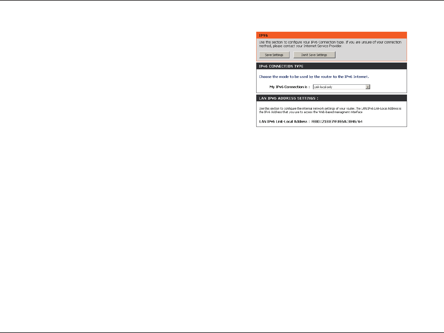
Section 3 - Conguration
Select Link-Local Only from the drop-down
menu.
Displays the IPv6 address of the router.
My IPv6 Connection:
LAN IPv6 Address
Settings:
Link-Local Connectivity

51D-Link DIR-835 User Manual
Section 3 - Conguration
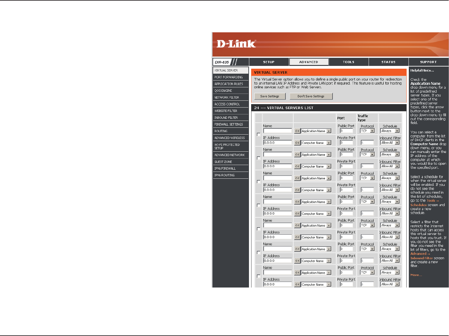
The DIR-835 can be congured as a virtual server so that remote users accessing Web or FTP services via the public IP address
can be automatically redirected to local servers in the LAN (Local Area Network).
The DIR-835 rewall feature lters out unrecognized packets to protect your LAN network so all computers networked with
the DIR-835 are invisible to the outside world. If you wish, you can make some of the LAN computers accessible from the
Internet by enabling Virtual Server. Depending on the requested service, the DIR-835 redirects the external service request to
the appropriate server within the LAN network.
The DIR-835 is also capable of port-redirection meaning incoming trac to a particular port may be redirected to a dierent
port on the server computer.
Each virtual service that is created will be listed at the bottom of the screen in the Virtual Servers List. There are pre-dened
virtual services already in the table. You may use them by enabling them and assigning the server IP to use that particular
virtual service.
For a list of ports for common applications, please visit http://support.dlink.com/faq/view.asp?prod_id=1191.
Virtual Server
Advanced
52D-Link DIR-835 User Manual
Section 3 - Conguration
This will allow you to open a single port. If you would like to open a range of ports, refer to the next page.
Enter a name for the rule or select an application
from the drop-down menu. Select an application
and click << to populate the elds.
Enter the IP address of the computer on your local
network that you want to allow the incoming
service to. If your computer is receiving an IP
address automatically from the router (DHCP), you
computer will be listed in the “Computer Name”
drop-down menu. Select your computer and click
<<.
Enter the port that you want to open next to Private
Port and Public Port. The private and public ports
are usually the same. The public port is the port
seen from the Internet side, and the private port
is the port being used by the application on the
computer within your local network.
Select TCP, UDP, or Both from the drop-down
menu.
The schedule of time when the Virtual Server Rule
will be enabled. The schedule may be set to Always,
which will allow the particular service to always be
enabled. You can create your own times in the Tools
> Schedules section.
Select Allow All (most common) or a created
Inbound lter. You may create your own inbound
lters in the Advanced > Inbound Filter page.
Name:
IP Address:
Private Port/
Public Port:
Protocol Type:
Schedule:
Inbound Filter:
53D-Link DIR-835 User Manual
Section 3 - Conguration
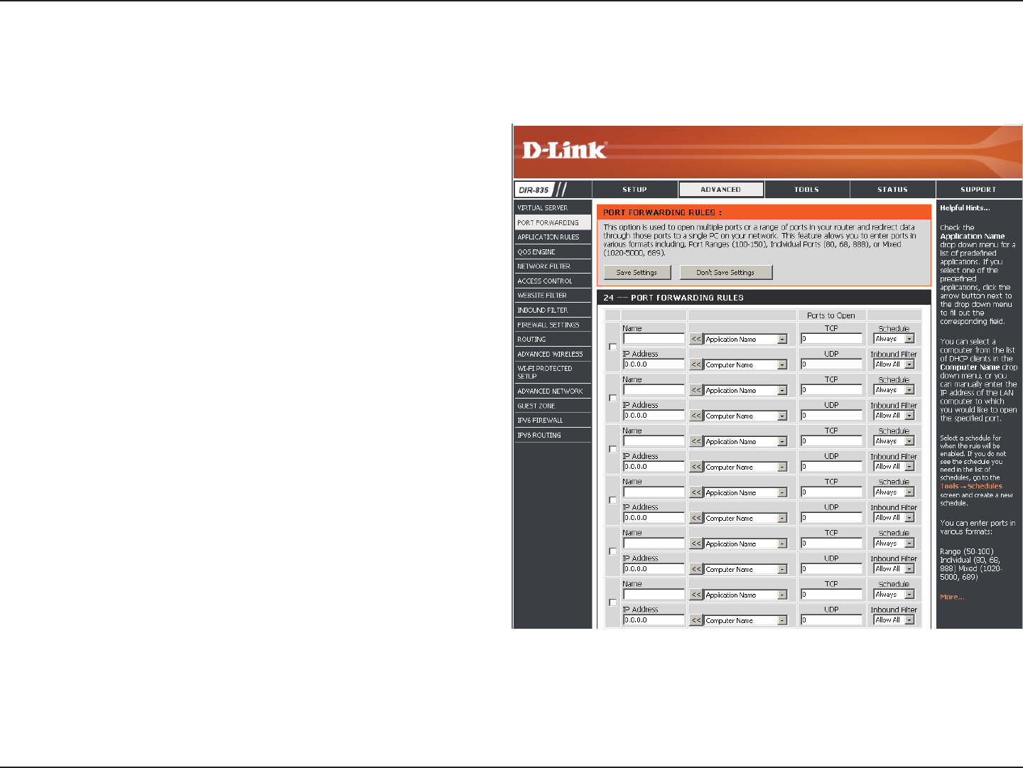
This will allow you to open a single port or a range of ports.
Port Forwarding
Enter a name for the rule or select an application
from the drop-down menu. Select an application
and click << to populate the elds.
Enter the IP address of the computer on your local
network that you want to allow the incoming service
to. If your computer is receiving an IP address
automatically from the router (DHCP), you computer
will be listed in the “Computer Name” drop-down
menu. Select your computer and click <<.
Enter the TCP and/or UDP port or ports that you
want to open. You can enter a single port or a range
of ports. Separate ports with a common.
Example: 24,1009,3000-4000
The schedule of time when the Virtual Server Rule
will be enabled. The schedule may be set to Always,
which will allow the particular service to always be
enabled. You can create your own times in the Tools
> Schedules section.
Select Allow All (most common) or a created
Inbound lter. You may create your own inbound
lters in the Advanced > Inbound Filter page.
Name:
IP Address:
TCP/UDP:
Schedule:
Inbound Filter:
54D-Link DIR-835 User Manual
Section 3 - Conguration
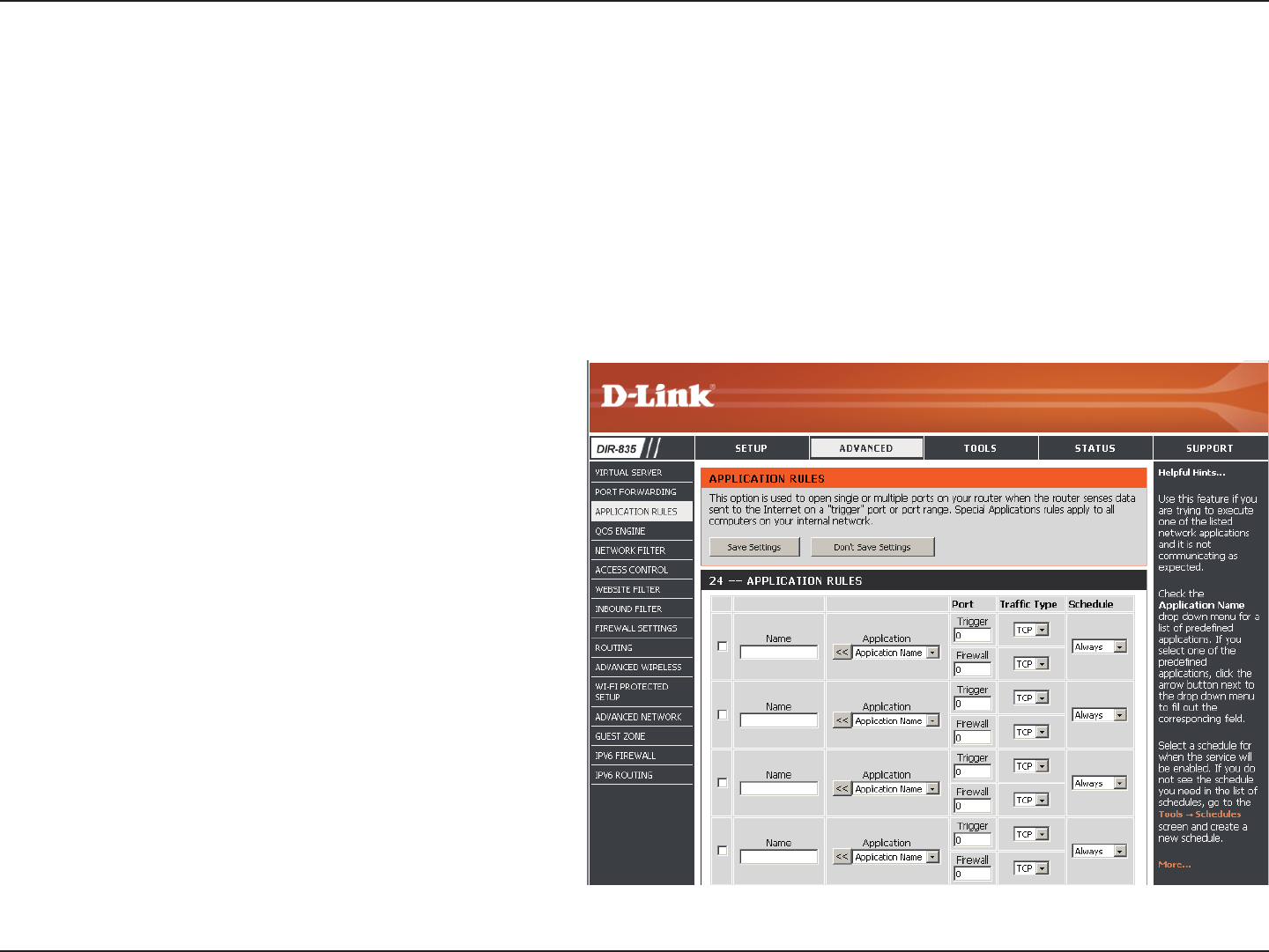
Enter a name for the rule. You may select a
pre-dened application from the drop-down menu
and click <<.
This is the port used to trigger the application. It
can be either a single port or a range of ports.
Select the protocol of the trigger port (TCP, UDP,
or Both).
This is the port number on the Internet side that
will be used to access the application. You may
dene a single port or a range of ports. You can use
a comma to add multiple ports or port ranges.
Select the protocol of the rewall port (TCP, UDP,
or Both).
The schedule of time when the Application Rule
will be enabled. The schedule may be set to Always,
which will allow the particular service to always
be enabled. You can create your own times in the
Tools > Schedules section.
Name:
Trigger:
Trac Type:
Firewall:
Trac Type:
Schedule:
Application Rules
Some applications require multiple connections, such as Internet gaming, video conferencing, Internet telephony and others.
These applications have diculties working through NAT (Network Address Translation). Special Applications makes some of
these applications work with the DIR-835. If you need to run applications that require multiple connections, specify the port
normally associated with an application in the “Trigger Port” eld, select the protocol type as TCP or UDP, then enter the rewall
(public) ports associated with the trigger port to open them for inbound trac.
The DIR-835 provides some predened applications in the table on the bottom of the web page. Select the application you
want to use and enable it.
55D-Link DIR-835 User Manual
Section 3 - Conguration
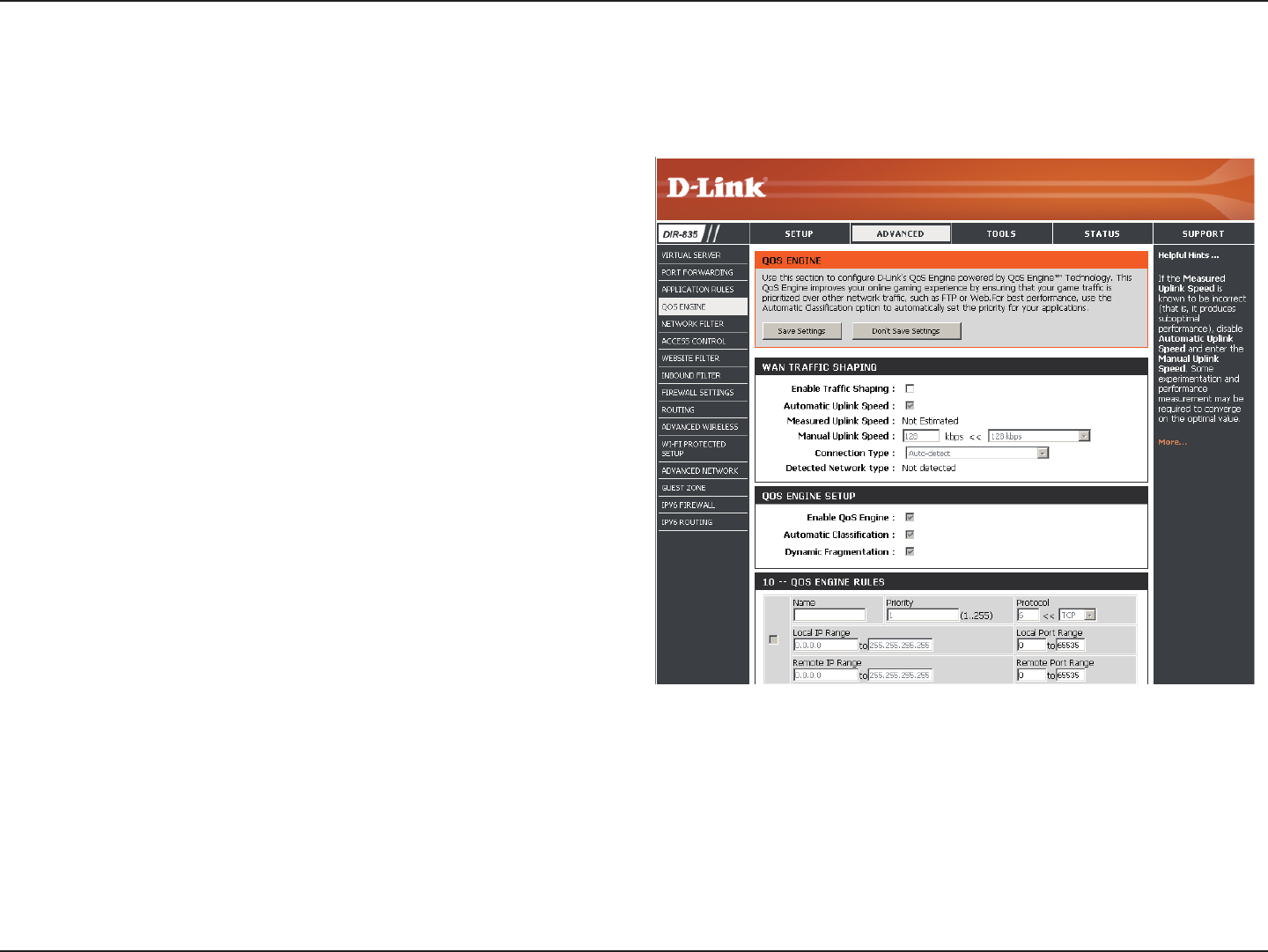
QoS Engine
This option is disabled by default. Enable this option for
better performance and experience with online games and
other interactive applications, such as VoIP.
This option is enabled by default when the QoS Engine
option is enabled. This option will allow your router to
automatically determine the uplink speed of your Internet
connection.
This displays the detected uplink speed.
The speed at which data can be transferred from the router
to your ISP. This is determined by your ISP. ISP’s often speed
as a download/upload pair. For example, 1.5Mbits/284Kbits.
Using this example, you would enter 284. Alternatively you
can test your uplink speed with a service such as www.
dslreports.com.
By default, the router automatically determines whether
the underlying connection is an xDSL/Frame-relay network
or some other connection type (such as cable modem or
Ethernet), and it displays the result as Detected xDSL or
Frame Relay Network. If you have an unusual network connection in which you are actually connected via xDSL but for which you
congure either “Static” or “DHCP” in the Internet settings, setting this option to xDSL or Other Frame Relay Network ensures that
the router will recognize that it needs to shape trac slightly dierently in order to give the best performance. Choosing xDSL or
Other Frame Relay Network causes the measured uplink speed to be reported slightly lower than before on such connections, but
gives much better results.
When Connection Type is set to automatic, the automatically detected connection type is displayed here.
This option is disabled by default. Enable this option for better performance and experience with online games and other interactive
applications, such as VoIP.
Enable Trac
Shaping:
Automatic Uplink
Speed:
Measured Uplink
Speed:
Manual Uplink
Speed:
Connection Type:
Detected Network
Type:
The QoS Engine option helps improve your network gaming performance by prioritizing applications. By default the QoS Engine settings are
disabled and application priority is not classied automatically.

56D-Link DIR-835 User Manual
Section 3 - Conguration
This option is enabled by default. This will allow your router to automatically determine the network priority of running
programs.
This option should be enabled when you have a slow Internet uplink. It helps to reduce the impact that large low priority network
packets can have on more urgent ones.
Enable QoS
Engine:
Automatic
Classication:
57D-Link DIR-835 User Manual
Section 3 - Conguration
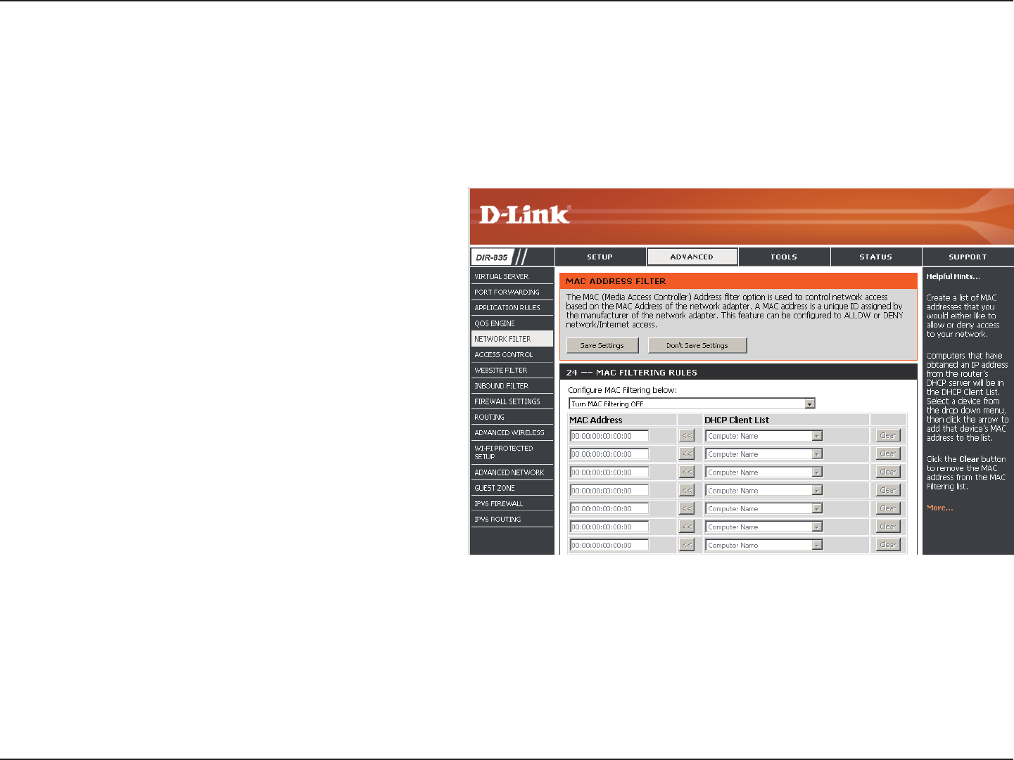
Network Filters
Select Turn MAC Filtering Off, Allow MAC
addresses listed below, or Deny MAC addresses
listed below from the drop-down menu.
Enter the MAC address you would like to lter.
To nd the MAC address on a computer, please
refer to the Networking Basics section in this
manual.
Select a DHCP client from the drop-down menu
and click << to copy that MAC Address.
Click to remove the MAC address.
Congure MAC
Filtering:
MAC Address:
DHCP Client:
Clear:
Use MAC (Media Access Control) Filters to allow or deny LAN (Local Area Network) computers by their MAC addresses from
accessing the network. You can either manually add a MAC address or select the MAC address from the list of clients that are
currently connected to the Broadband Router.
58D-Link DIR-835 User Manual
Section 3 - Conguration
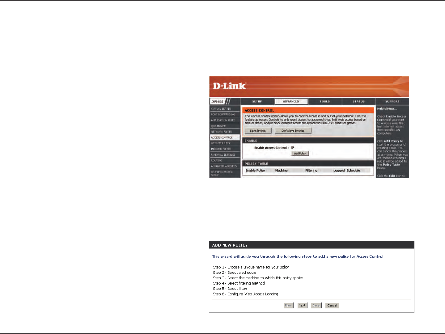
Access Control
Click the Add Policy button to start the Access
Control Wizard.
Add Policy:
The Access Control section allows you to control access in and out of your network. Use this feature as Parental Controls to
only grant access to approved sites, limit web access based on time or dates, and/or block access from applications like P2P
utilities or games.
Click Next to continue with the wizard.
Access Control Wizard
59D-Link DIR-835 User Manual
Section 3 - Conguration
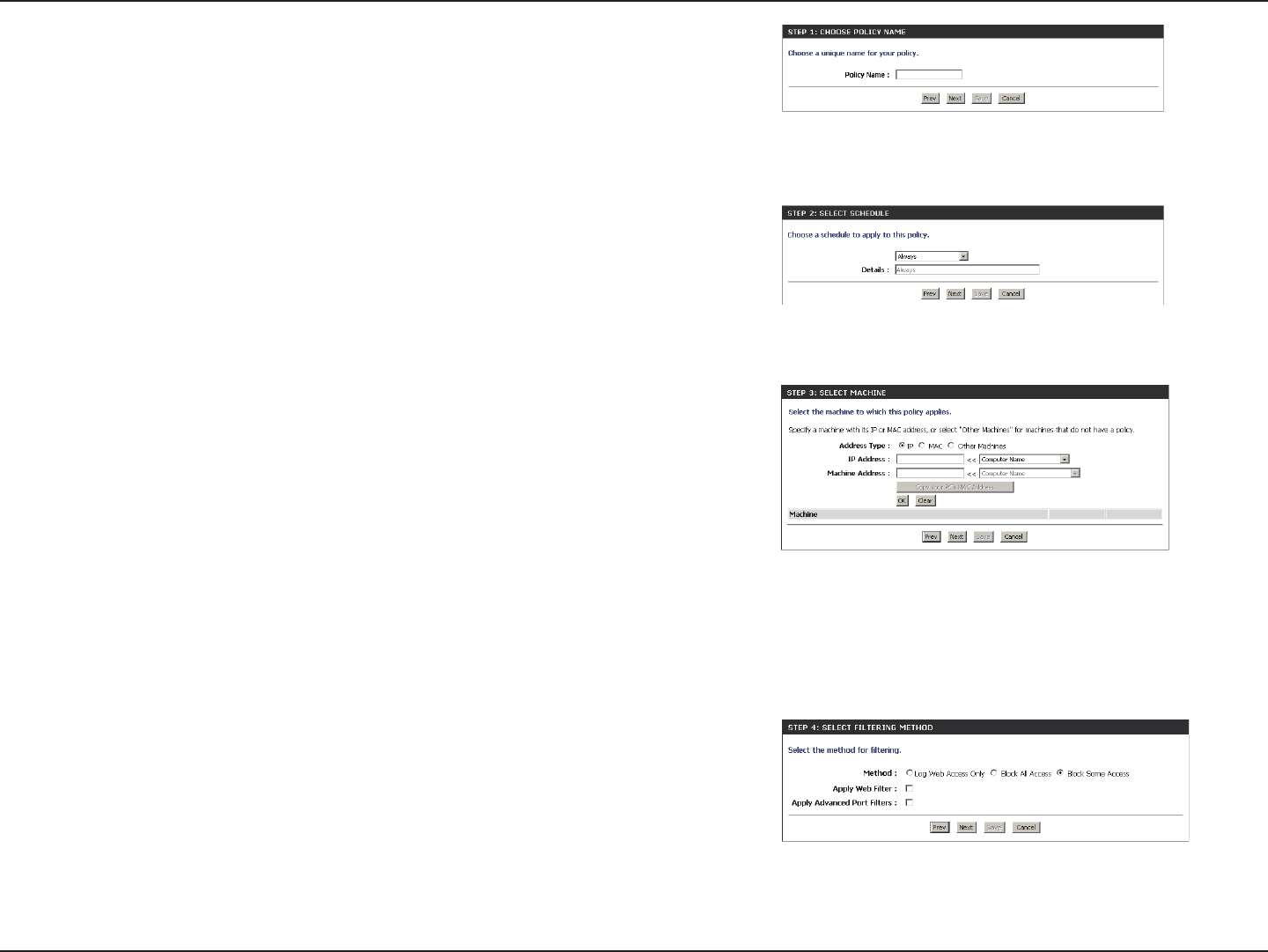
Enter a name for the policy and then click Next to continue.
Select a schedule (I.E. Always) from the drop-down menu and
then click Next to continue.
Enter the following information and then click Next to continue.
• Address Type - Select IP address, MAC address, or Other
Machines.
• IP Address - Enter the IP address of the computer you want to
apply the rule to.
• Machine Address - Enter the PC MAC address (i.e. 00:00.00.00.00).
Select the ltering method and then click Next to continue.
60D-Link DIR-835 User Manual
Section 3 - Conguration
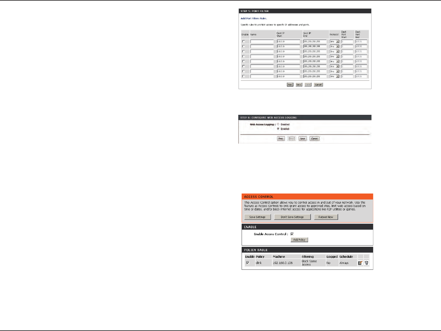
Enter the rule:
Enable - Check to enable the rule.
Name - Enter a name for your rule.
Dest IP Start - Enter the starting IP address.
Dest IP End - Enter the ending IP address.
Protocol - Select the protocol.
Dest Port Start - Enter the starting port number.
Dest Port End - Enter the ending port number.
To enable web logging, click Enable.
Click Save to save the access control rule.
Your newly created policy will now show up under Policy Table.
61D-Link DIR-835 User Manual
Section 3 - Conguration
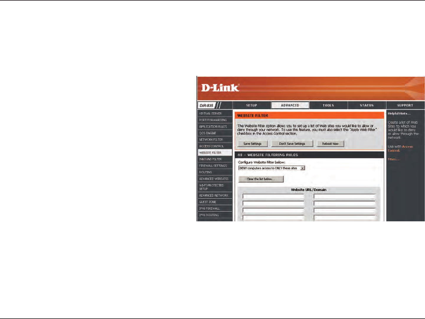
Add Website
Filtering Rule:
Website URL/
Domain:
Website Filters
Select Allow or Deny.
Enter the keywords or URLs that you want to allow
or block. Click Save Settings.
Website Filters are used to allow you to set up a list of Web sites that can be viewed by multiple users through the network.
To use this feature select to Allow or Deny, enter the domain or website and click Save Settings. You must also select Apply
Web Filter under the Access Control section (page 45).
62D-Link DIR-835 User Manual
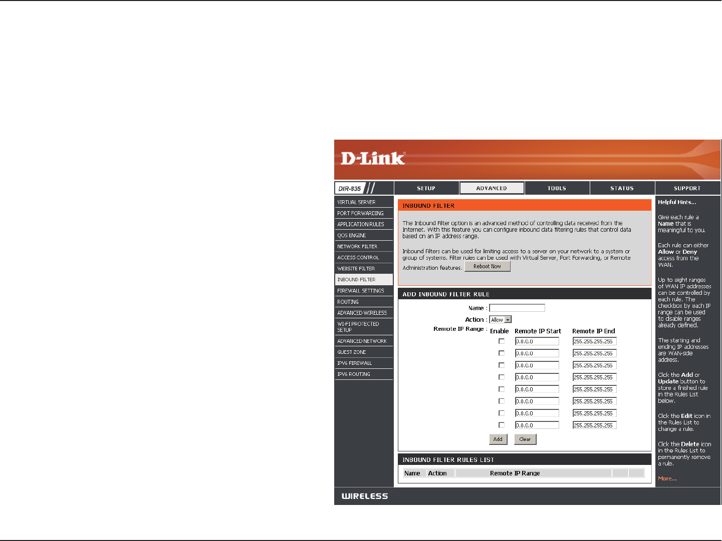
Section 3 - Conguration
Enter a name for the inbound lter rule.
Select Allow or Deny.
Check to enable rule.
Enter the starting IP address. Enter 0.0.0.0 if you
do not want to specify an IP range.
Enter the ending IP address. Enter 255.255.255.255
if you do not want to specify and IP range.
Click the Add button to apply your settings. You
must click Save Settings at the top to save the
settings.
This section will list any rules that are created. You
may click the Edit icon to change the settings or
enable/disable the rule, or click the Delete icon
to remove the rule.
Name:
Action:
Enable:
Remote IP Start:
Remote IP End:
Add:
Inbound Filter
Rules List:
The Inbound Filter option is an advanced method of controlling data received from the Internet. With this feature you can
congure inbound data ltering rules that control data based on an IP address range. Inbound Filters can be used with Virtual
Server, Port Forwarding, or Remote Administration features.
Inbound Filters
63D-Link DIR-835 User Manual
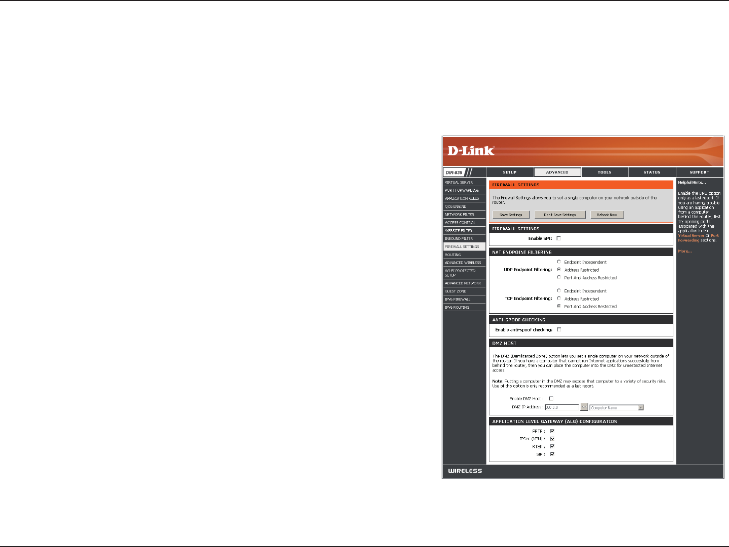
Section 3 - Conguration
SPI (Stateful Packet Inspection, also known as dynamic packet ltering)
helps to prevent cyber attacks by tracking more state per session. It
validates that the trac passing through the session conforms to the
protocol.
Select one of the following for TCP and UDP ports:
Endpoint Independent - Any incoming trac sent to an open port
will be forwarded to the application that opened the port. The port
will close if idle for 5 minutes.
Address Restricted - Incoming trac must match the IP address of
the outgoing connection.
Address + Port Restriction - Incoming trac must match the IP address
and port of the outgoing connection.
Enable this feature to protect your network from certain kinds of
“spoong” attacks.
If an application has trouble working from behind the router, you can
expose one computer to the Internet and run the application on that
computer.
Note: Placing a computer in the DMZ may expose that computer to a
variety of security risks. Use of this option is only recommended as a last
resort.
Specify the IP address of the computer on the LAN that you want to have unrestricted Internet communication. If this computer
obtains it’s IP address automatically using DHCP, be sure to make a static reservation on the Setup > Network Settings page so
that the IP address of the DMZ machine does not change.
Enable SPI:
NAT Endpoint
Filtering:
Anti-Spoof Check:
Enable DMZ:
DMZ IP Address:
Firewall Settings
A rewall protects your network from the outside world. The DIR-835 oers a rewall type functionality. The SPI feature helps
prevent cyber attacks. Sometimes you may want a computer exposed to the outside world for certain types of applications.
If you choose to expose a computer, you can enable DMZ. DMZ is short for Demilitarized Zone. This option will expose the
chosen computer completely to the outside world.
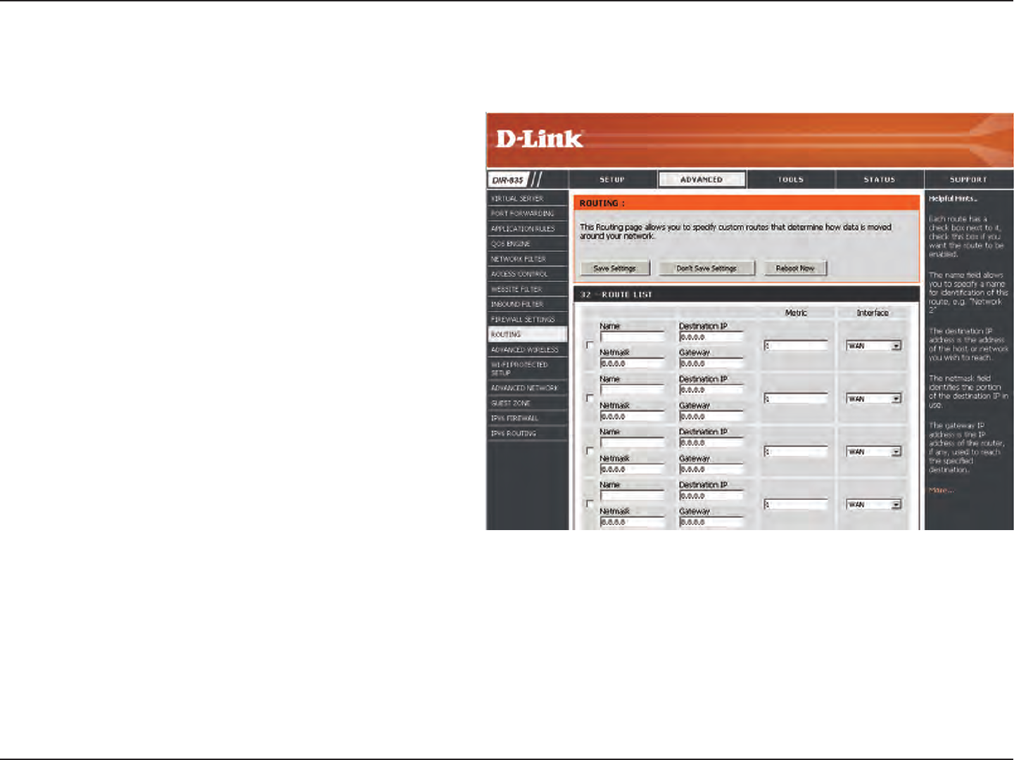
64D-Link DIR-835 User Manual
Section 3 - Conguration
Enter the IP address of packets that will take this
route.
Enter the netmask of the route, please note
that the octets must match your destination IP
address.
Enter your next hop gateway to be taken if this
route is used.
The route metric is a value from 1 to 16 that
indicates the cost of using this route. A value 1 is
the lowest cost and 15 is the highest cost.
Select the interface that the IP packet must use to
transit out of the router when this route is used.
Destination IP:
Netmask:
Gateway:
Metric:
Interface:
Routing
The Routing option is an advanced method of customizing specic routes of data through your network.
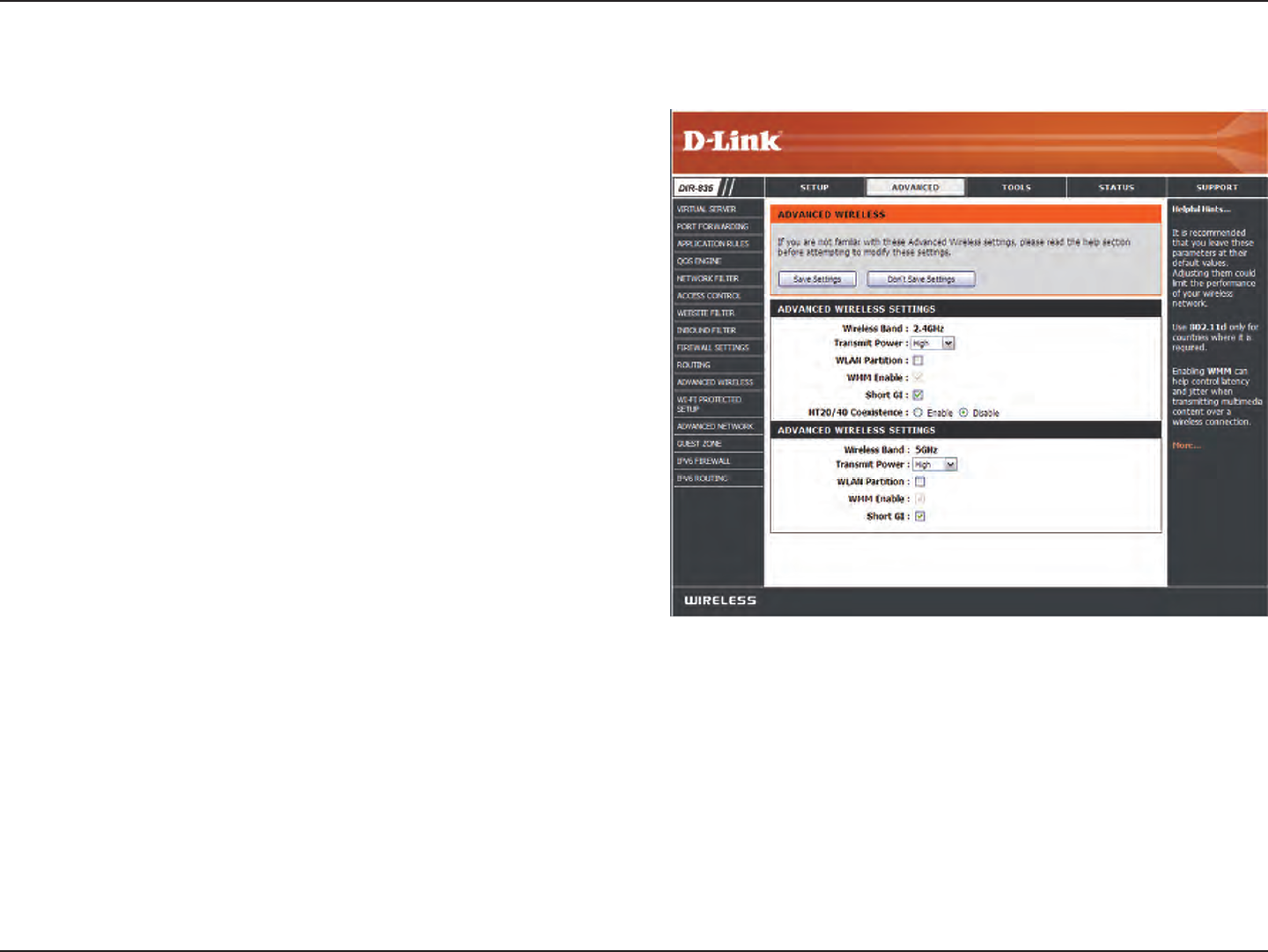
65D-Link DIR-835 User Manual
Section 3 - Conguration
Advanced Wireless
Set the transmit power of the antennas.
This enables 802.11d operation. 802.11d is a wireless
specication developed to allow implementation of wireless
networks in countries that cannot use the 802.11 standard.
This feature should only be enabled if you are in a country
that requires it.
WMM is QoS for your wireless network. This will improve
the quality of video and voice applications for your wireless
clients.
Check this box to reduce the guard interval time therefore
increasing the data capacity. However, it’s less reliable and
may create higher data loss.
Select to Enable or Disable this feature.
Transmit Power:
WLAN Partition:
WMM Enable:
Short GI:
HT20/40
Coexistence:
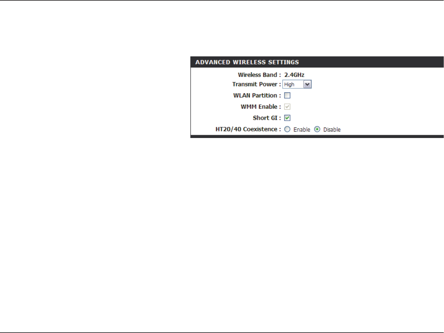
66D-Link DIR-835 User Manual
Section 3 - Conguration
Set the transmit power of the antennas.
Enable this option to prevent associated
wireless clients from communicating with
each other.
WMM is QoS for your wireless network. This
will improve the quality of video and voice
applications for your wireless clients. Check
to enable this feature.
Check this box to reduce the guard interval time therefore increasing the data capacity. However, it’s less reliable and may create
higher data loss.
Select to Enable or Disable this feature.
Transmit Power:
WLAN Partition:
WMM Function:
Short GI:
HT20/40
Coexistence:
Advanced Wireless Settings
802.11n/g (2.4GHz)
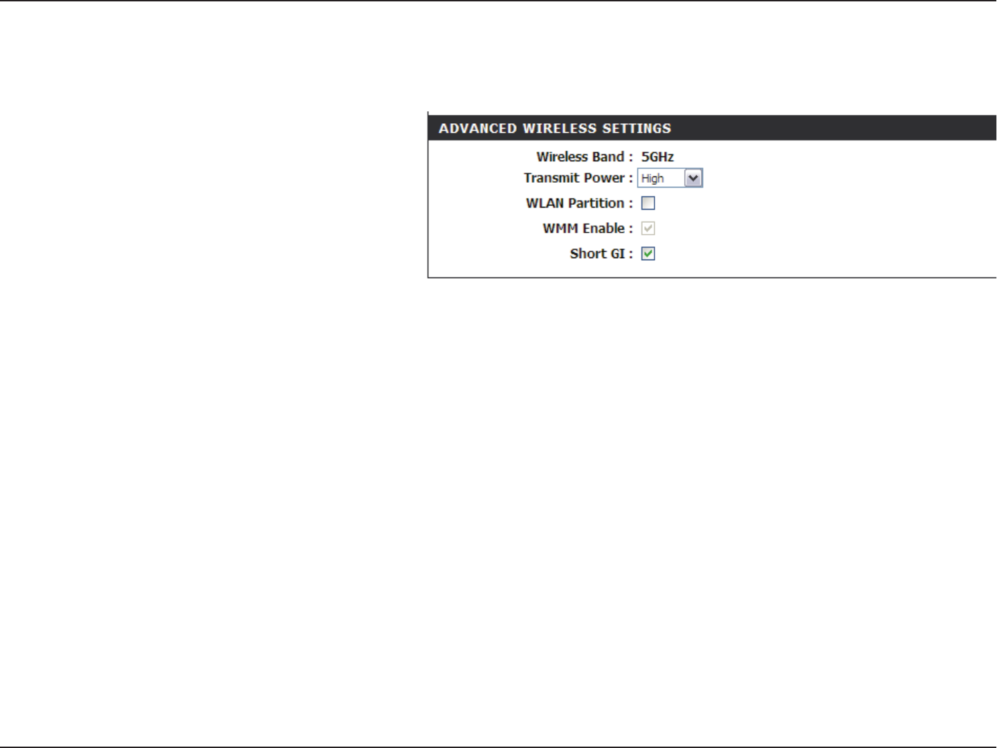
67D-Link DIR-835 User Manual
Section 3 - Conguration
Advanced Wireless Settings
802.11n/a (5GHz)
Set the transmit power of the antennas.
Enable this option to prevent associated
wireless clients from communicating with
each other.
WMM is QoS for your wireless network. This
will improve the quality of video and voice
applications for your wireless clients. Check
to enable this feature.
Check this box to reduce the guard interval time therefore increasing the data capacity. However, it’s less reliable and may create
higher data loss.
Transmit Power:
WLAN Partition:
WMM Function:
Short GI:
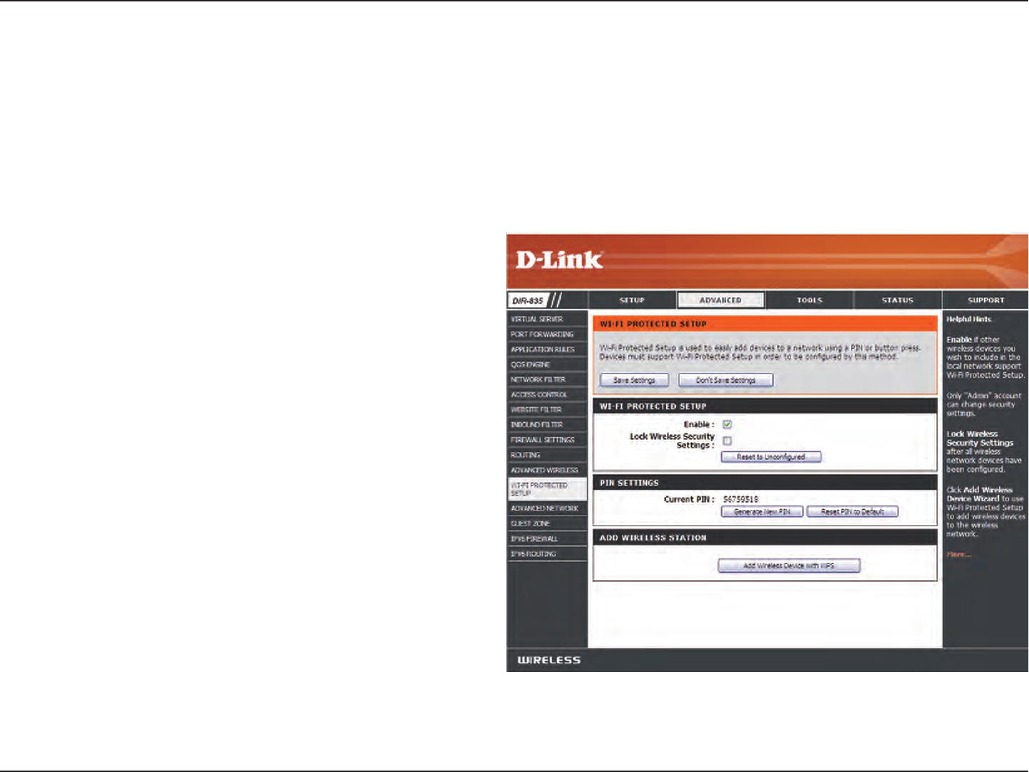
68D-Link DIR-835 User Manual
Section 3 - Conguration
Wi-Fi Protected Setup (WPS)
Enable the Wi-Fi Protected Setup feature.
Locking the wireless security settings prevents the
settings from being changed by the Wi-Fi Protected
Setup feature of the router. Devices can still be added
to the network using Wi-Fi Protected Setup. However,
the settings of the network will not change once this
option is checked.
A PIN is a unique number that can be used to add
the router to an existing network or to create a new
network. The default PIN may be printed on the bottom
of the router. For extra security, a new PIN can be
generated. You can restore the default PIN at any time.
Only the Administrator (“admin” account) can change
or reset the PIN.
Shows the current value of the router’s PIN.
Restore the default PIN of the router.
Create a random number that is a valid PIN. This
becomes the router’s PIN. You can then copy this PIN to
the user interface of the registrar.
Enable:
Lock Wireless
Security
Settings:
PIN Settings:
Current PIN:
Reset PIN to
Default:
Generate New
PIN:
Wi-Fi Protected Setup (WPS) System is a simplied method for securing your wireless network during the “Initial setup” as well
as the “Add New Device” processes. The Wi-Fi Alliance (WFA) has certied it across dierent products as well as manufactures.
The process is just as easy, as depressing a button for the Push-Button Method or correctly entering the 8-digit code for the
Pin-Code Method. The time reduction in setup and ease of use are quite benecial, while the highest wireless Security setting
of WPA2 is automatically used.

69D-Link DIR-835 User Manual
Section 3 - Conguration
This Wizard helps you add wireless devices to the wireless network.
The wizard will either display the wireless network settings to guide you through manual conguration, prompt you to enter the
PIN for the device, or ask you to press the conguration button on the device. If the device supports Wi-Fi Protected Setup and has a
conguration button, you can add it to the network by pressing the conguration button on the device and then the on the router
within 60 seconds. The status LED on the router will ash three times if the device has been successfully added to the network.
There are several ways to add a wireless device to your network. A “registrar” controls access to the wireless network. A registrar
only allows devices onto the wireless network if you have entered the PIN, or pressed a special Wi-Fi Protected Setup button on the
device. The router acts as a registrar for the network, although other devices may act as a registrar as well.
Start the wizard.
Add Wireless
Station:
Add Wireless
Device Wizard:
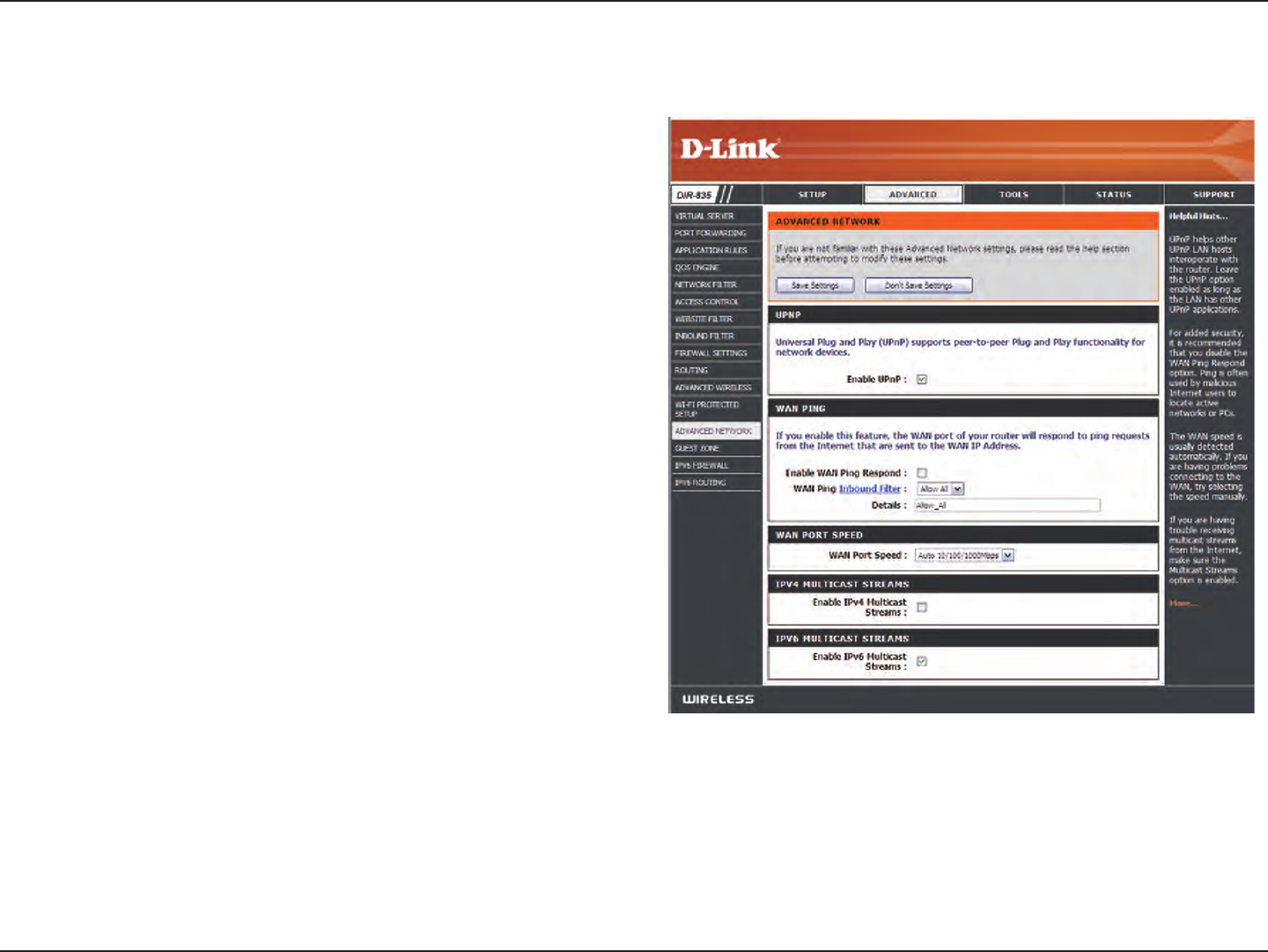
70D-Link DIR-835 User Manual
Section 3 - Conguration
UPnP
Internet Ping Block
Internet Port Speed
Multicast Streams
To use the Universal Plug and Play (UPnP™) feature
click on Enabled. UPNP provides compatibility with
networking equipment, software and peripherals.
Unchecking the box will not allow the DIR-835 to
respond to pings. Blocking the Ping may provide some
extra security from hackers. Check the box to allow
the Internet port to be “pinged”.
Select from the drop-down menu if you would like
to apply the Inbound Filter to the WAN ping. Refer
to page 47 for more information regarding Inbound
Filter.
You may set the port speed of the Internet port to
10Mbps, 100Mbps, or auto. Some older cable or DSL
modems may require you to set the port speed to
10Mbps.
Check the box to allow multicast traffic to pass
through the router from the Internet.
Check the box to allow IPv6 multicast trac.
Enable UPnP:
WAN Ping:
WAN Ping Inbound
Filter:
WAN Port Speed:
Multicast streams:
Enable IPV6
Multicast Streams:
Advanced Network Settings
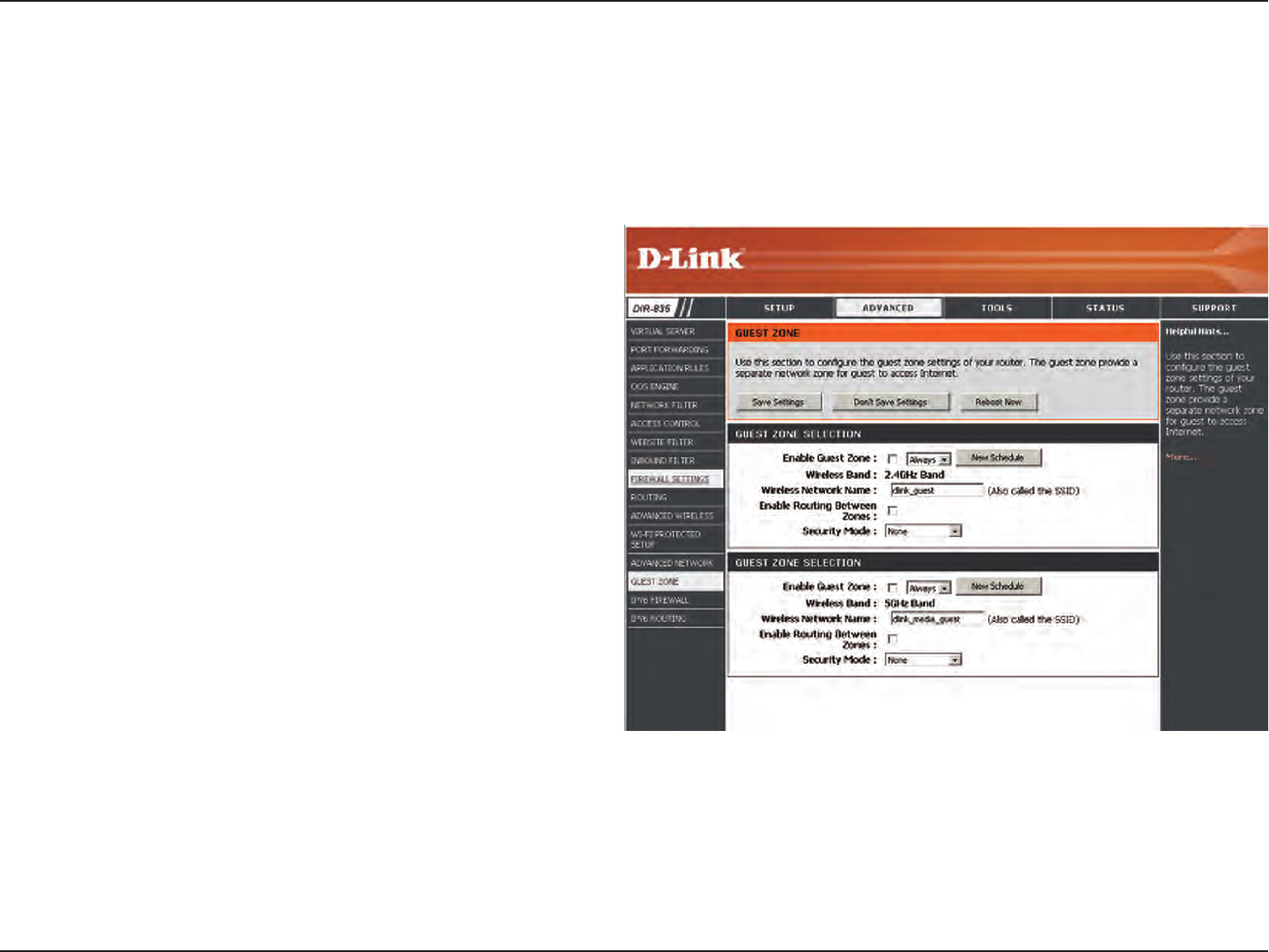
71D-Link DIR-835 User Manual
Section 3 - Conguration
Guest Zone
Check to enable the Guest Zone feature.
The schedule of time when the Guest Zone will be
active. The schedule may be set to Always, which will
allow the particular service to always be enabled. You
can create your own times in the Tools > Schedules
section.
Enter a wireless network name (SSID) that is dierent
from your main wireless network.
Check to allow network connectivity between the
dierent zones created.
Select the type of security or encryption you would
like to enable for the guest zone.
Enable Guest
Zone:
Schedule:
Wireless
Network Name:
Enable Routing
Between Zones:
Security Mode:
The Guest Zone feature will allow you to create temporary zones that can be used by guests to access the Internet. These
zones will be separate from your main wireless network. You may congure dierent zones for the 2.4GHz and 5.0GHz wireless
bands.
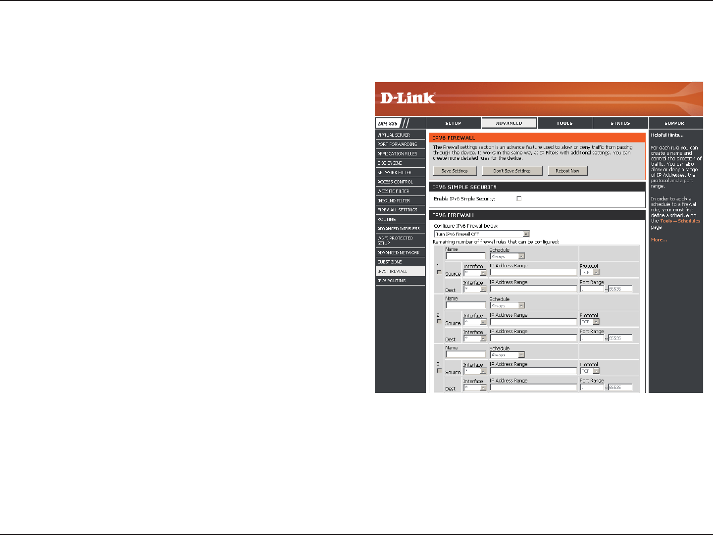
72D-Link DIR-835 User Manual
Section 3 - Conguration
IPv6 Firewall
The DIR-835’s IPv6 Firewall feature allows you to congure which kind of IPv6 trac is allowed to pass through the device. The
DIR-835’s IPv6 Firewall functions in a similar way to the IP Filters feature.
Check the box to enable the IPv6 rewall simple security.
Enter a name to identify the IPv6 rewall rule.
Use the radio buttons to Allow or Deny transport of the
IPv6 data packets according to the criteria dened in the
rewall rule.
Use the Source drop-down menu to specify the interface
that connects to the source IPv6 addresses of the rewall
rule.
Enter the source IPv6 address range in the adjacent IP
Address Range eld.
Use the Dest drop-down menu to specify the interface that
connects to the destination IP addresses of the rewall rule.
Enable Checkbox:
Name:
Action:
Source:
IP Address Range:
Dest:
Use the drop-down menu to select the time schedule that
the IPv6 Firewall Rule will be enabled on. The schedule may
be set to Always, which will allow the particular service to
always be enabled. You can create your own times in the
Tools > Schedules section.
Select the protocol of the rewall port (All, TCP, UDP, or ICMP).
Enter the rst port of the range that will be used for the rewall rule in the top port range eld and enter the last port in the eld
underneath.
Select Schedule:
Protocol:
Port Range:
Click the Save Settings button to save any changes made.
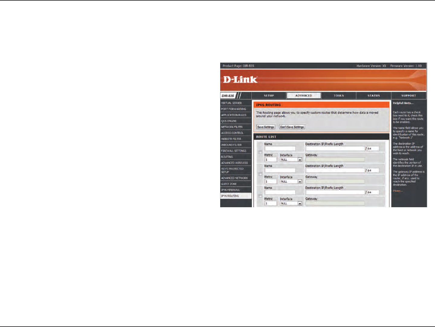
73D-Link DIR-835 User Manual
Section 3 - Conguration
IPv6 Routing
Check the box next to the route you wish to enable.
Enter a specic name to identify this route.
Enter the host or network address you wish to reach.
This is the IP address of the router used to reach the
specied destination.
Route List:
Name:
Destination IP:
Gateway IP:
This page allows you to specify custom routes that determine how data is moved around your network.
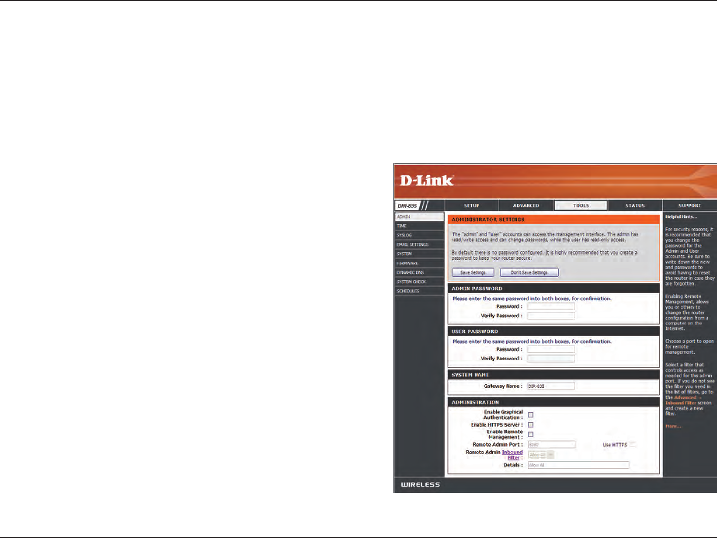
74D-Link DIR-835 User Manual
Section 3 - Conguration
Admin
This page will allow you to change the Administrator and User passwords. You can also enable Remote Management. There are
two accounts that can access the management interface through the web browser. The accounts are admin and user. Admin
has read/write access while user has read-only access. User can only view the settings but cannot make any changes. Only the
admin account has the ability to change both admin and user account passwords.
Tools
Enter a new password for the Administrator Login Name. The administrator
can make changes to the settings.
Enter the new password for the User login. If you login as the User, you
cannot change the settings (you can only view them).
Enter a name for the DIR-835 router.
Enter a name for the router.
Enables a challenge-response test to require users to type letters or
numbers from a distorted image displayed on the screen to prevent online
hackers and unauthorized users from gaining access to your router’s
network settings.
Check to enable HTTPS to connect to the router securely.
Remote management allows the DIR-835 to be congured from the
Internet by a web browser. A username and password is still required to
access the Web-Management interface. In general, only a member of your
network can browse the built-in web pages to perform Administrator
tasks. This feature enables you to perform Administrator tasks from the
remote (Internet) host. The port number used to access the DIR-835.
Example: http://x.x.x.x:8080 whereas x.x.x.x is the Internet IP address of
the DIR-835 and 8080 is the port used for the Web Management interface.
If you have enabled HTTPS Server and checked Use HTTPS, you must
enter https:// as part of the URL to access the router remotely.
This section will list any rules that are created. You may click the Edit icon to change the settings or enable/disable the rule, or click the Delete icon to
remove the rule.
Admin Password:
User Password:
Gateway Name:
Enable Graphical
Authentication:
Enable HTTPS
Server:
Enable Remote
Management:
Remote Admin
Inbound Filter:
Details:
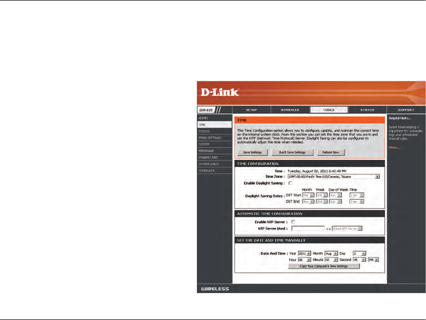
75D-Link DIR-835 User Manual
Section 3 - Conguration
Time
Select the Time Zone from the drop-down
menu.
To select Daylight Saving time manually, select
enabled or disabled, and enter a start date and
an end date for daylight saving time.
NTP is short for Network Time Protocol. NTP
synchronizes computer clock times in a network
of computers. Check this box to use a NTP server.
This will only connect to a server on the Internet,
not a local server.
Enter the NTP server or select one from the drop-
down menu.
To manually input the time, enter the values
in these elds for the Year, Month, Day, Hour,
Minute, and Second and then click Set Time.
You can also click Copy Your Computer’s Time
Settings.
Time Zone:
Daylight
Saving:
Enable NTP
Server:
NTP Server
Used:
Manual:
The Time Conguration option allows you to congure, update, and maintain the correct time on the internal system clock.
From this section you can set the time zone that you are in and set the Time Server. Daylight Saving can also be congured to
automatically adjust the time when needed.
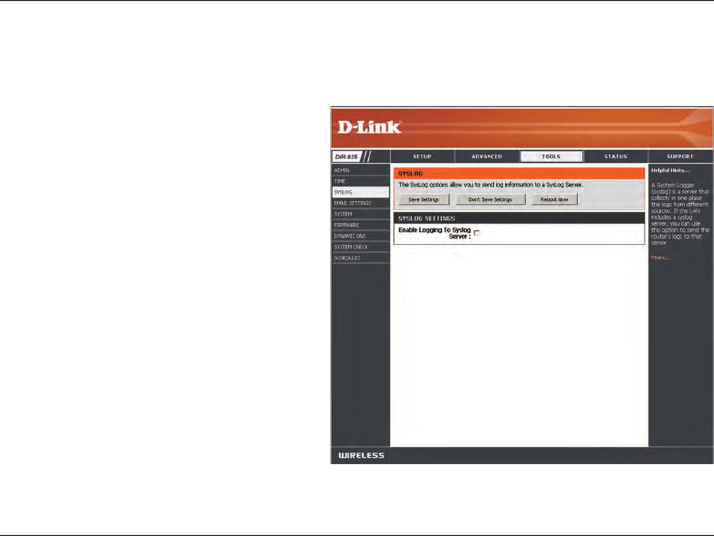
76D-Link DIR-835 User Manual
Section 3 - Conguration
SysLog
The Broadband Router keeps a running log of events and activities occurring on the Router. You may send these logs to a
SysLog server on your network.
Enable Logging to
SysLog Server:
SysLog Server IP
Address:
Check this box to send the router logs to a SysLog
Server.
The address of the SysLog server that will be
used to send the logs. You may also select your
computer from the drop-down menu (only
if receiving an IP address from the router via
DHCP).
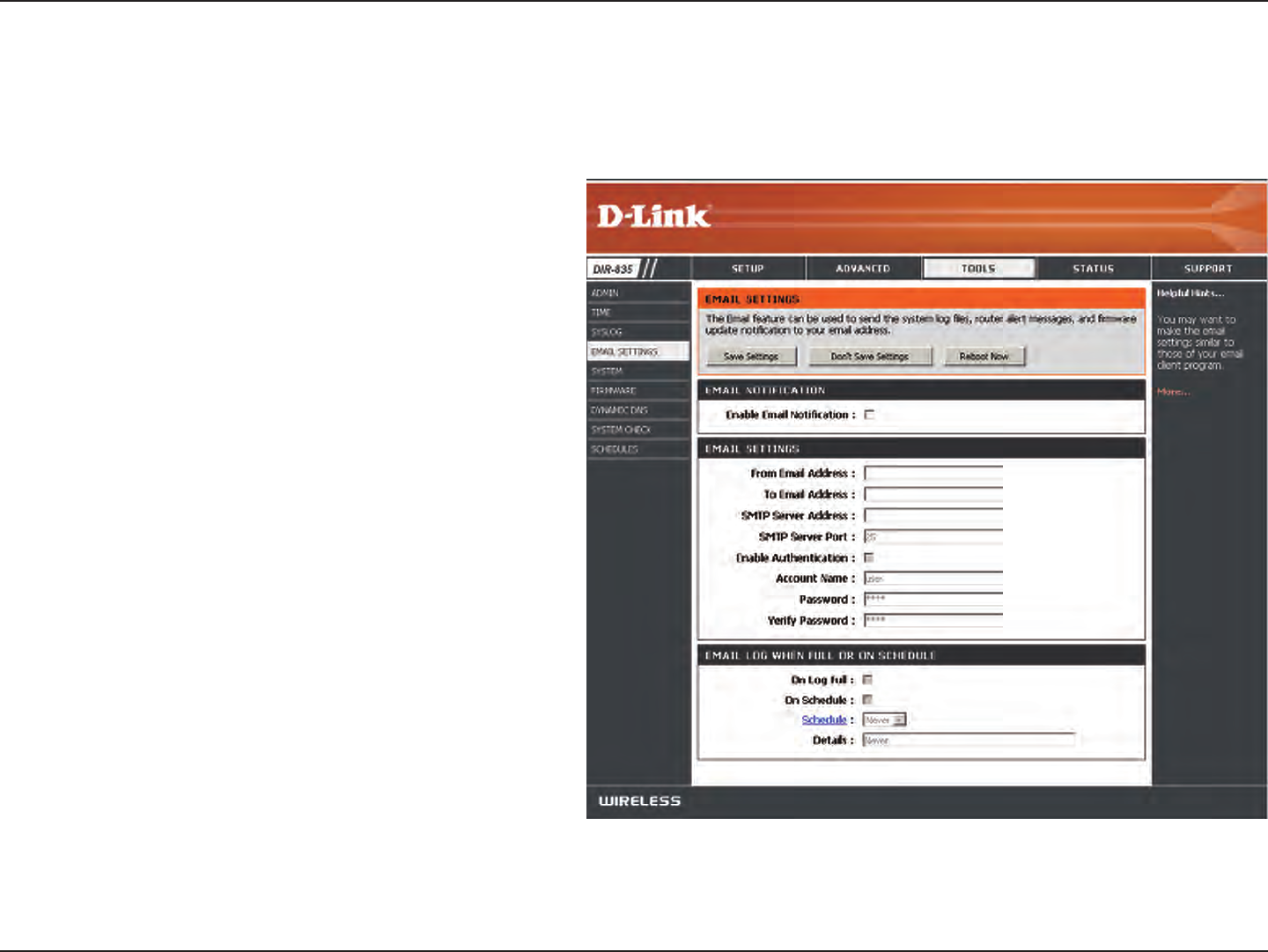
77D-Link DIR-835 User Manual
Section 3 - Conguration
Email Settings
The Email feature can be used to send the system log les, router alert messages, and rmware update notication to your
email address.
Enable Email
Notication:
From Email
Address:
To Email Address:
SMTP Server
Address:
Enable
Authentication:
Account Name:
Password:
On Log Full:
On Schedule:
Schedule:
When this option is enabled, router activity logs
are emailed to a designated email address.
This email address will appear as the sender
when you receive a log le or rmware upgrade
notication via email.
Enter the email address where you want the email
sent.
Enter the SMTP server address for sending email.
If your SMTP server requires authentication, select
this option.
Check this box if your SMTP server requires
authentication.
Enter your account for sending email.
Enter the password associated with the account.
Re-type the password associated with the account.
When this option is selected, logs will be sent via
email to your account when the log is full.
Selecting this option will send the logs via email
according to schedule.
This option is enabled when On Schedule is selected. You can select a schedule from the list of dened schedules. To create a
schedule, go to Tools > Schedules.
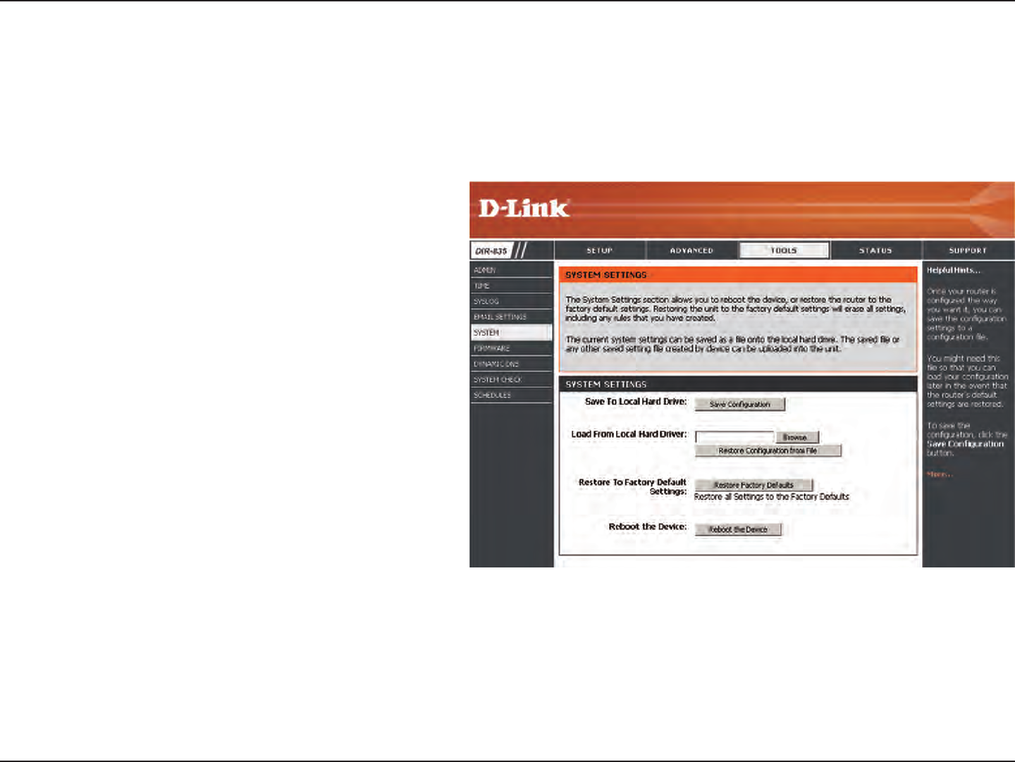
78D-Link DIR-835 User Manual
Section 3 - Conguration
Use this option to save the current router
conguration settings to a le on the hard disk of
the computer you are using. First, click the Save
button. A le dialog will appear, allowing you to
select a location and le name for the settings.
Use this option to load previously saved
router configuration settings. First, use the
Browse option to nd a previously saved le
of conguration settings. Then, click the Load
button to transfer those settings to the router.
This option will restore all conguration settings
back to the settings that were in eect at the time
the router was shipped from the factory. Any
settings that have not been saved will be lost,
including any rules that you have created. If you
want to save the current router conguration
settings, use the Save button above.
Click to reboot the router.
Save Settings
to Local Hard
Drive:
Load Settings
from Local
Hard Drive:
Restore
to Factory
Default
Settings:
Reboot
Device:
System
This section allows you to manage the router’s conguration settings, reboot the router, and restore the router to the factory
default settings. Restoring the unit to the factory default settings will erase all settings, including any rules that you’ve
created.
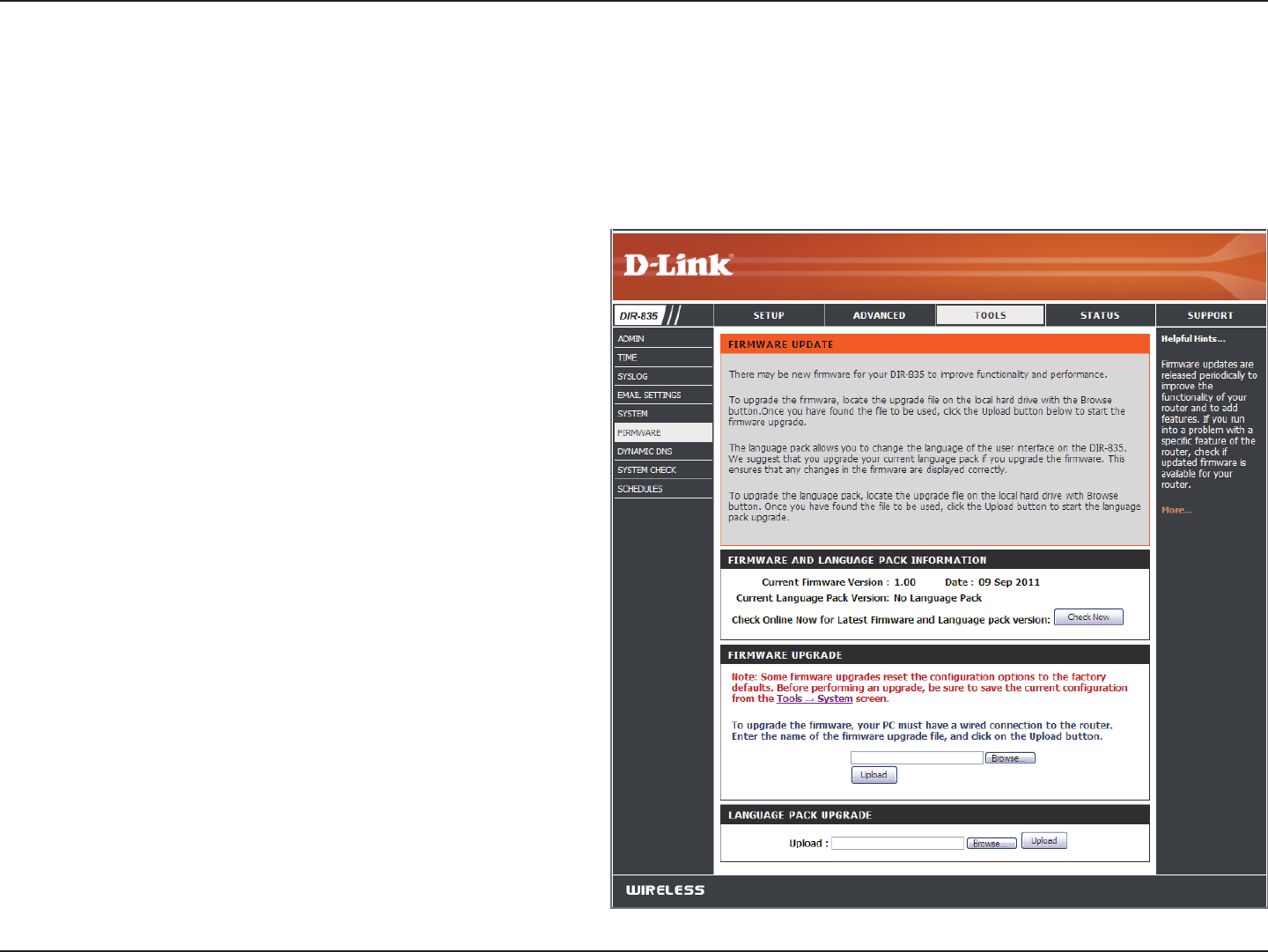
79D-Link DIR-835 User Manual
Section 3 - Conguration
Firmware
Browse:
Upload:
After you have downloaded the new rmware, click
Browse to locate the rmware update on your hard
drive. Click Upload to complete the rmware upgrade.
Once you have a rmware update on your computer,
use this option to browse for the le and then upload
the information into the access point.
You can upgrade the rmware of the access point here. Make sure the rmware you want to use is on the local hard drive of
the computer. Click on Browse to locate the rmware le to be used for the update. Please check the D-Link support website
for rmware updates at http://support.dlink.com. You can download rmware upgrades to your hard drive from this site.
After you have downloaded the new language pack,
click Browse to locate the language pack le on your
hard drive. Click Upload to complete the language
pack upgrade.
Language Pack
You can change the language of the web UI by uploading
available language packs.
Browse:
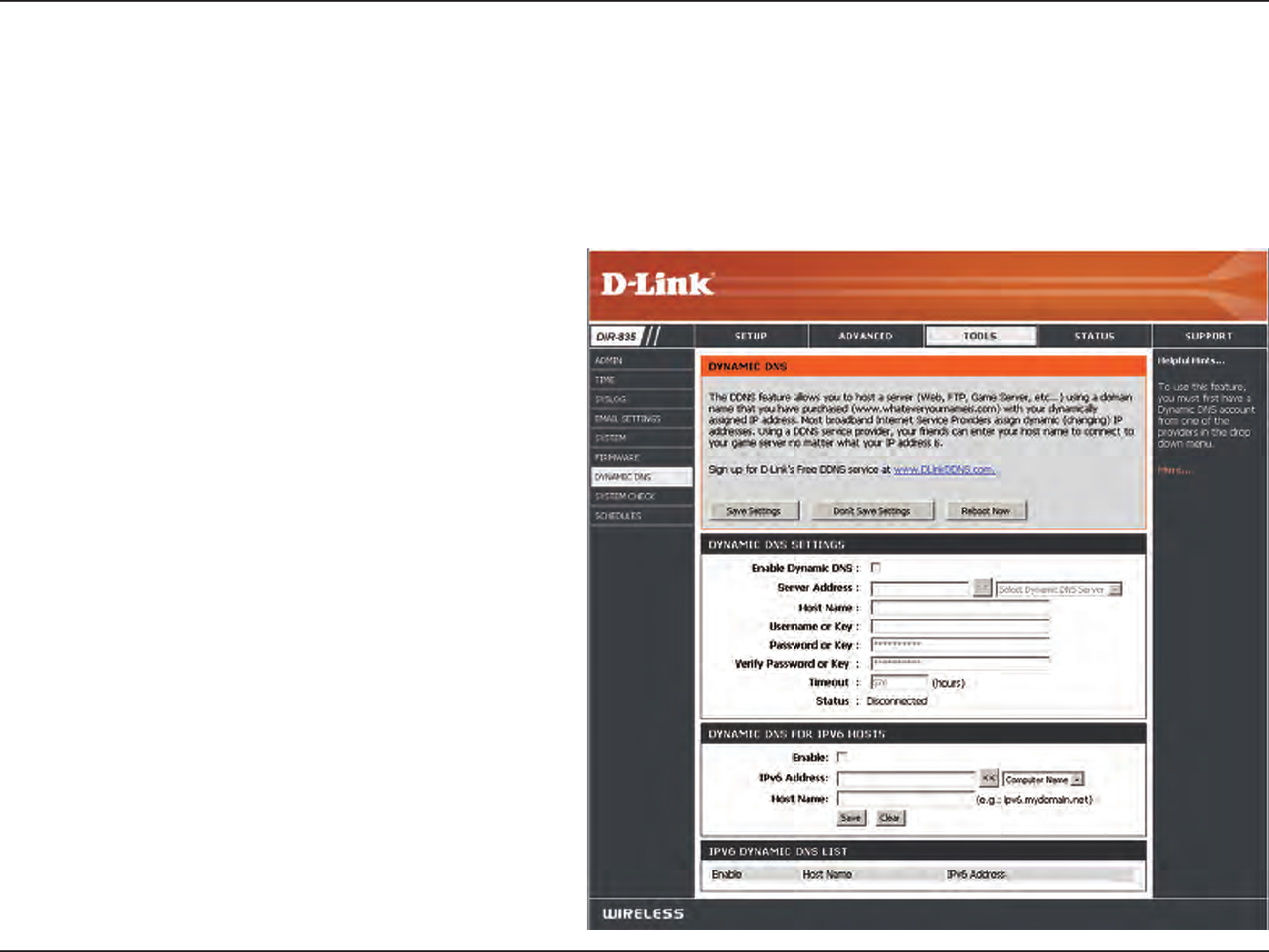
80D-Link DIR-835 User Manual
Section 3 - Conguration
Dynamic Domain Name System is a method of
keeping a domain name linked to a changing IP
Address. Check the box to enable DDNS.
Choose your DDNS provider from the drop down
menu.
Enter the Host Name that you registered with
your DDNS service provider.
Enter the Username for your DDNS account.
Enter the Password for your DDNS account.
Enter a time (in hours).
Displays the current connection status.
DDNS for IPv6 Hosts
Enable
Dynamic DNS:
Server
Address:
Host Name:
Username or
Key:
Password or
Key:
Timeout:
Status:
Dynamic DNS
The DDNS feature allows you to host a server (Web, FTP, Game Server, etc…) using a domain name that you have purchased
(www.whateveryournameis.com) with your dynamically assigned IP address. Most broadband Internet Service Providers assign
dynamic (changing) IP addresses. Using a DDNS service provider, your friends can enter in your domain name to connect to
your server no matter what your IP address is.
Enable:
IPv6
Address:
Check the box to enable DDNS for IPv6 Hosts.
Enter the IPv6 address of your computer/server
in your local network. You can click the << button
and select a computer/server from the drop-down
list.

81D-Link DIR-835 User Manual
Section 3 - Conguration
Host Name:
IPv6 DDNS
List:
Enable:
Host Name:
IPv6 Address:
Edit/Delete:
Enter the IPv6 Host Name that you registered with your DDNS service provider.
Once you save your entry, the IPv6 DDNS host information will be displayed here.
Check to enable the entry.
Displays the name of your IPv6 DDNS host.
Displays the IPv6 address of your computer/server associated with the IPv6 DDNS host.
Click the edit icon to make changes to the entry or click the delete icon to remove the entry.
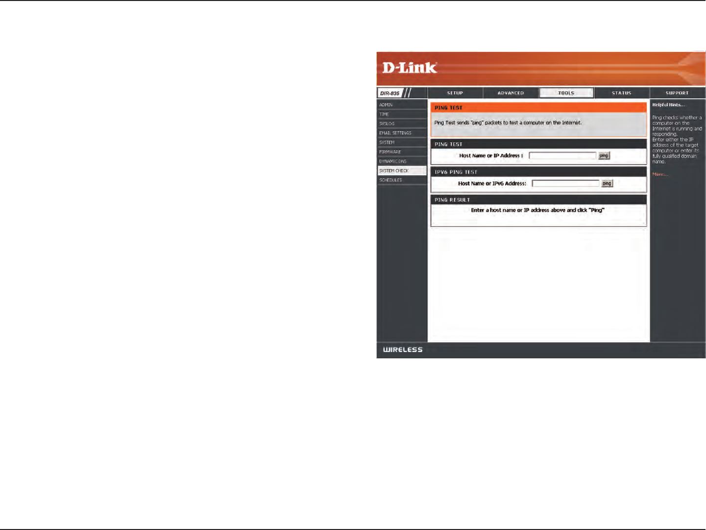
82D-Link DIR-835 User Manual
Section 3 - Conguration
The Ping Test is used to send Ping packets to test if a
computer is on the Internet. Enter the IP Address that you
wish to Ping, and click Ping.
The results of your ping attempts will be displayed here.
System Check
Ping Test:
Ping Results:
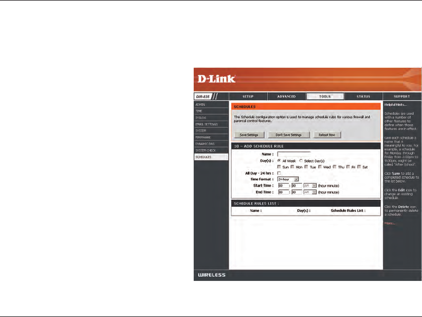
83D-Link DIR-835 User Manual
Section 3 - Conguration
Enter a name for your new schedule.
Select a day, a range of days, or All Week to include
every day.
Check All Day - 24hrs or enter a start and end
time for your schedule.
You must click Save Settings at the top for your
schedules to go into eect.
The list of schedules will be listed here. Click the
Edit icon to make changes or click the Delete icon
to remove the schedule.
Name:
Days:
Time:
Save:
Schedule Rules
List:
Schedules
Schedules can be created for use with enforcing rules. For example, if you want to restrict web access to Mon-Fri from 3pm to
8pm, you could create a schedule selecting Mon, Tue, Wed, Thu, and Fri and enter a Start Time of 3pm and End Time of 8pm.
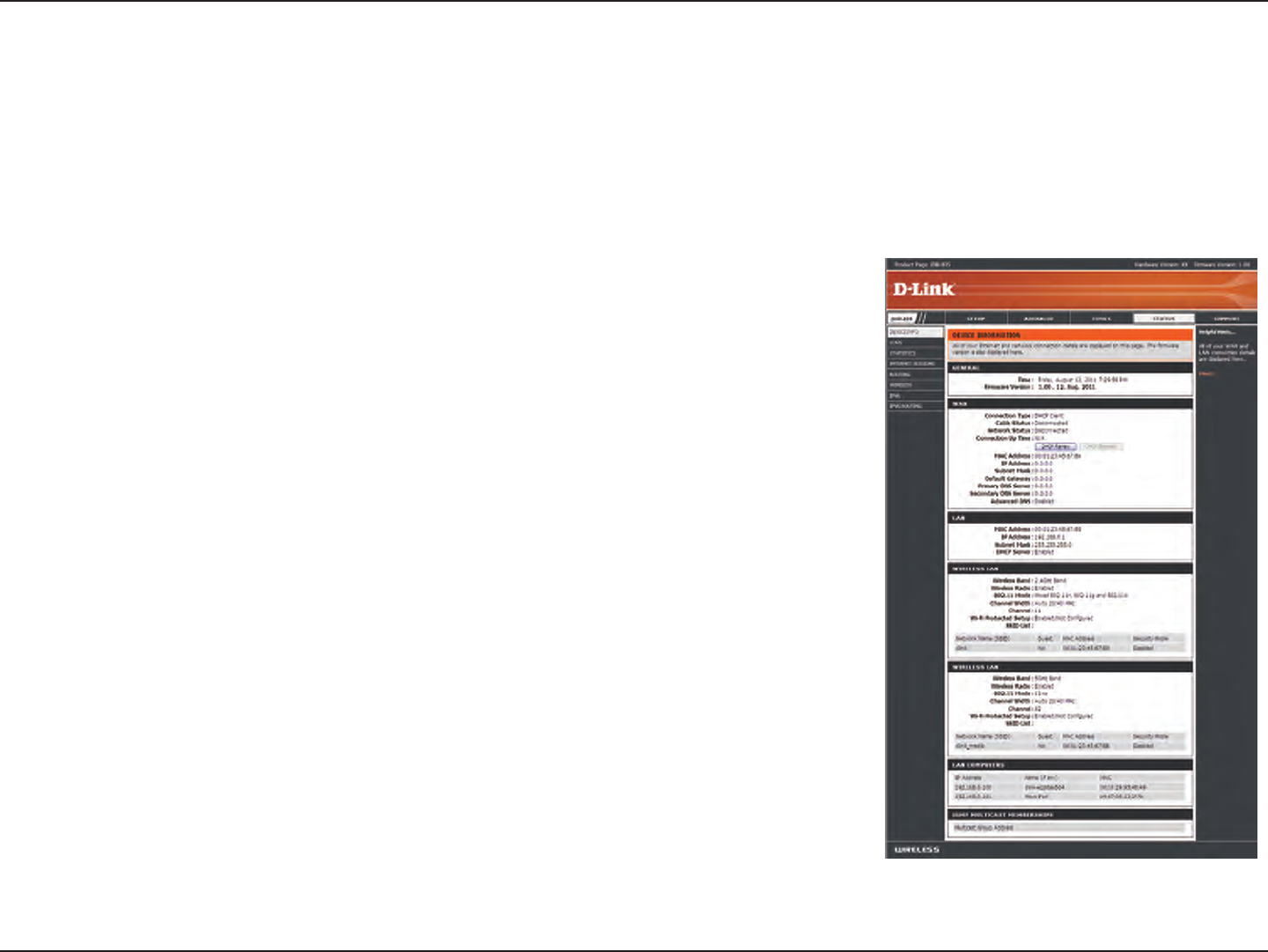
84D-Link DIR-835 User Manual
Section 3 - Conguration
This page displays the current information for the DIR-835. It will display the LAN, WAN (Internet), and Wireless information. If
your Internet connection is set up for a Dynamic IP address then a Release button and a Renew button will be displayed. Use
Release to disconnect from your ISP and use Renew to connect to your ISP.
If your Internet connection is set up for PPPoE, a Connect button and a Disconnect
button will be displayed. Use Disconnect to drop the PPPoE connection and use
Connect to establish the PPPoE connection.
Displays the router’s time and rmware version.
Displays the MAC address and the public IP settings
Displays the MAC address and the private (local) IP settings for the router.
Displays the wireless MAC address and your wireless settings such as SSID and
Channel.
Displays computers and devices that are connected to the router via Ethernet
and that are receiving an IP address assigned by the router (DHCP).
General:
WAN:
LAN:
Wireless LAN:
LAN Computers:
Device Info
Status
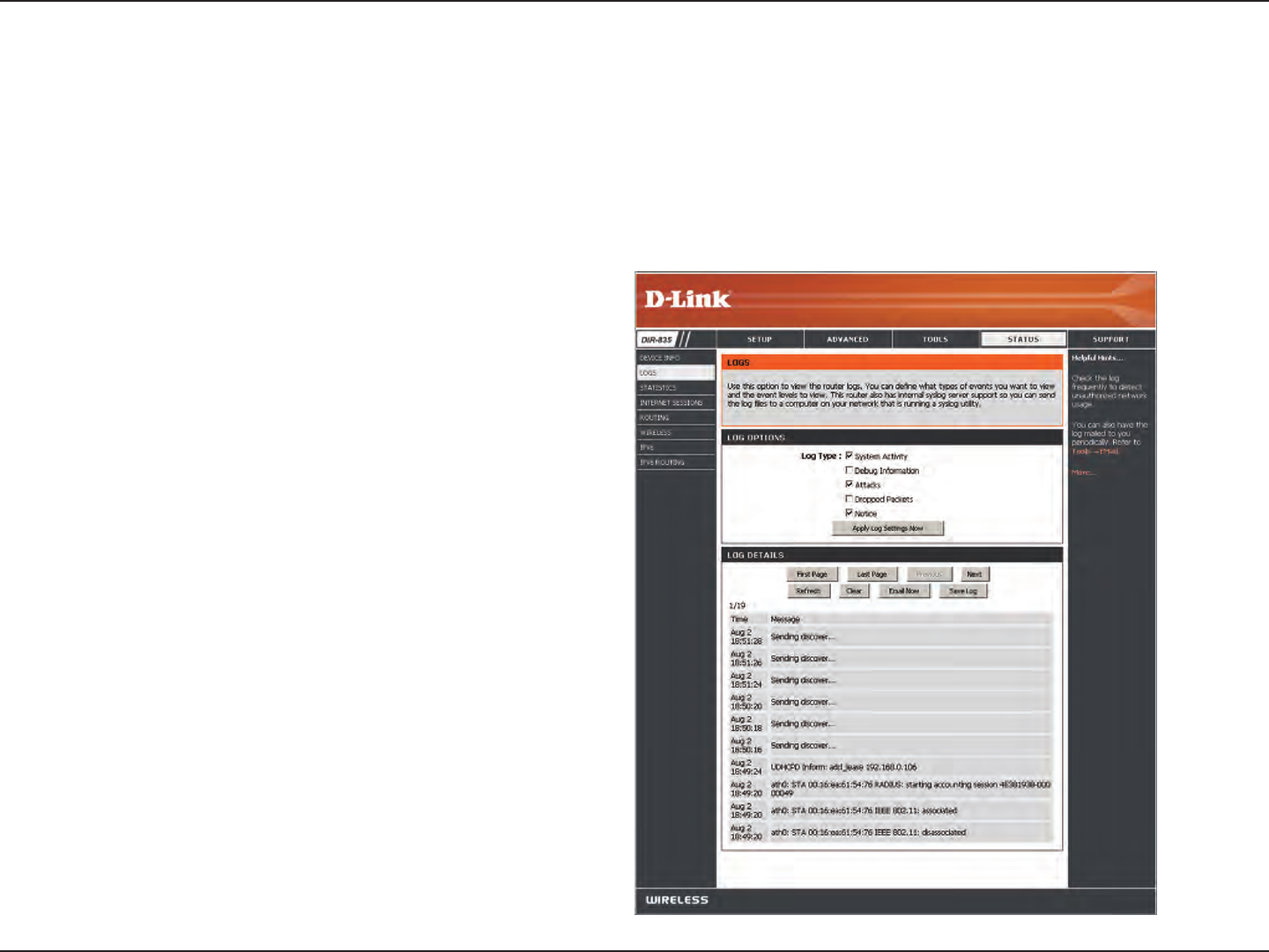
85D-Link DIR-835 User Manual
Section 3 - Conguration
Logs
Log Options:
Refresh:
Clear:
Email Now:
Save Log:
You can select the types of messages that you want
to display from the log. System Activity, Debug
Information, Attacks, Dropped Packets, and Notice
messages can be selected. Click Apply Log Settings
Now to activate your settings.
Updates the log details on the screen so it displays any
recent activity.
Clears all of the log contents.
This option will send a copy of the router log to your
email address congured in the Tools > Email Settings
screen.
This option will save the router log to a le on your
computer.
The router automatically logs (records) events of possible interest in it’s internal memory. If there isn’t enough internal memory
for all events, logs of older events are deleted but logs of the latest events are retained. The Logs option allows you to view
the router logs. You can dene what types of events you want to view and the level of the events to view. This router also has
external Syslog Server support so you can send the log les to a computer on your network that is running a Syslog utility.
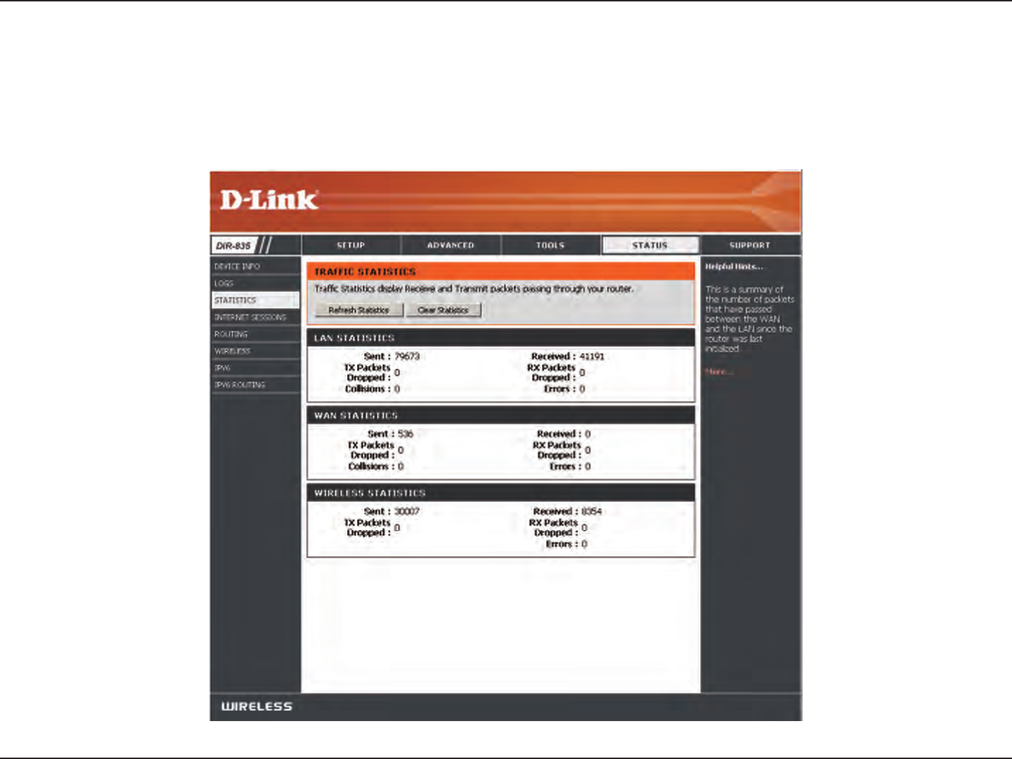
86D-Link DIR-835 User Manual
Section 3 - Conguration
Statistics
The screen below displays the Trac Statistics. Here you can view the amount of packets that pass through the DIR-835 on both
the WAN, LAN ports and both the 802.11n/g (2.4GHz) and 802.11n/a (5GHz) wireless bands. The trac counter will reset if the
device is rebooted.
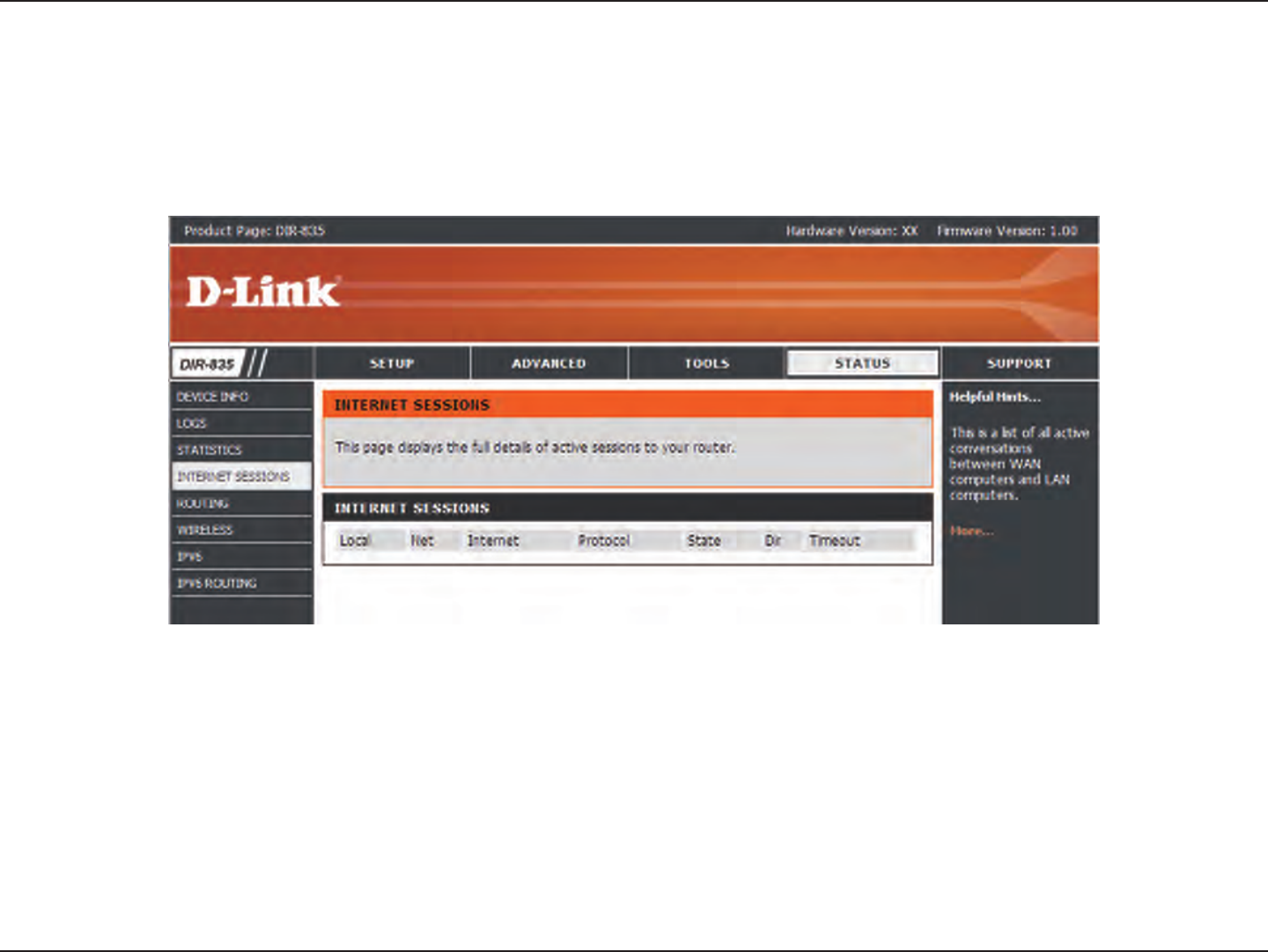
87D-Link DIR-835 User Manual
Section 3 - Conguration
Internet Sessions
The Internet Sessions page displays full details of active Internet sessions through your router. An Internet session is a conversation
between a program or application on a LAN-side computer and a program or application on a WAN-side computer.
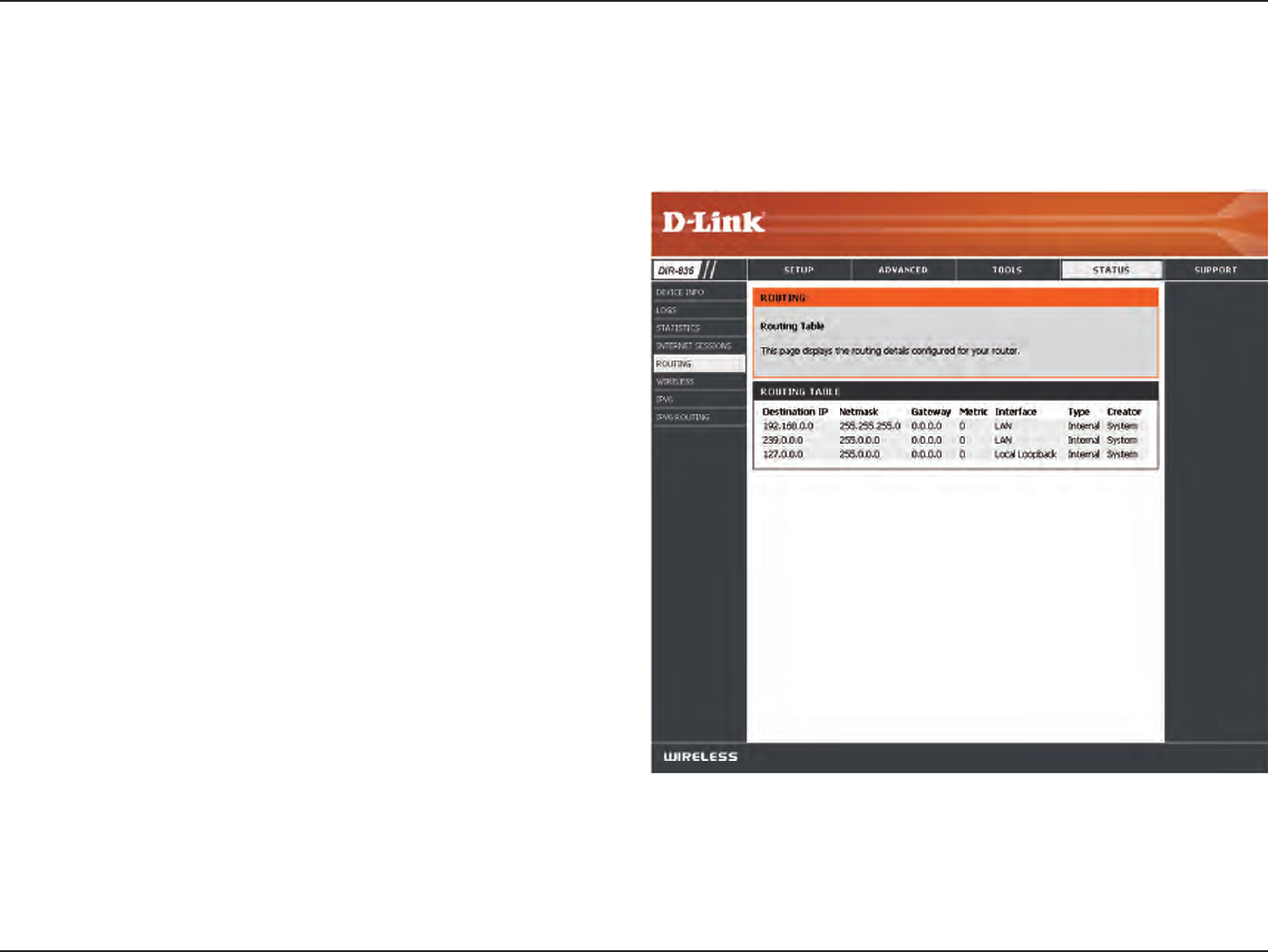
88D-Link DIR-835 User Manual
Section 3 - Conguration
Routing
The Routing option is an advanced method of customizing specic routes of data through your network.
Use the drop-down menu to specify if the IP packet must
use the WAN or LAN interface to transit out of the Router.
Enter the IP address of the packets that will take this route.
Enter the subnet mask to specify the subnet of the IP
packets that will take this route.
Enter the next hop that will be taken if this route is used.
Interface:
Destination IP:
Subnet Mask:
Gateway:
Click the Save Settings button to save any changes made.
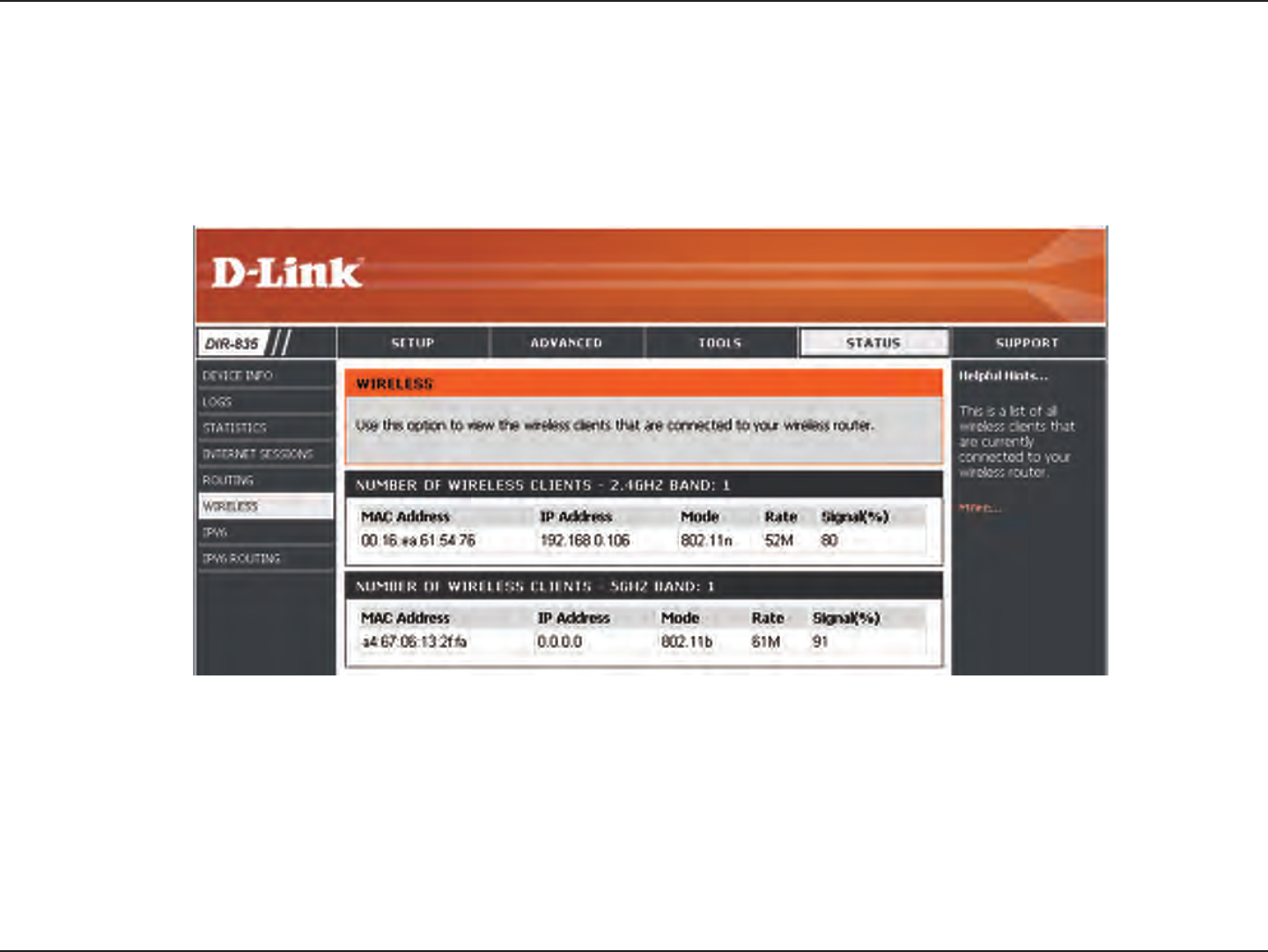
89D-Link DIR-835 User Manual
Section 3 - Conguration
The wireless client table displays a list of current connected wireless clients. This table also displays the connection time and
MAC address of the connected wireless clients.
Wireless
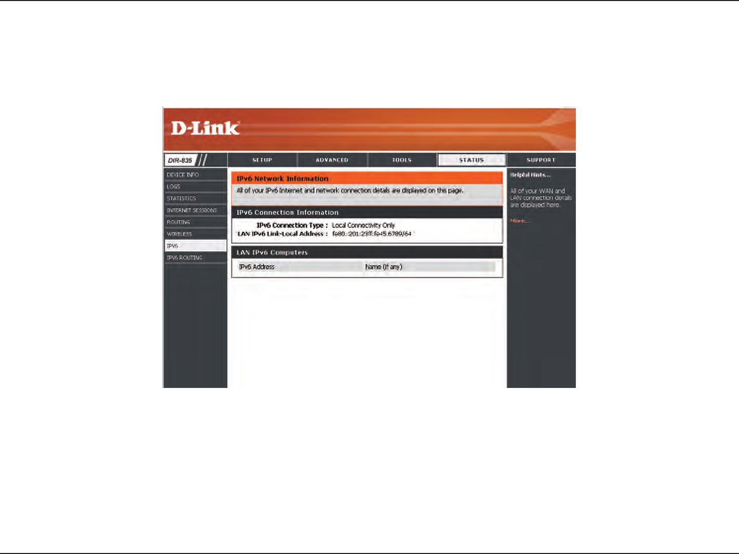
90D-Link DIR-835 User Manual
Section 3 - Conguration
IPv6
The IPv6 page displays a summary of the Router’s IPv6 settings and lists the IPv6 address and host name of any IPv6 clients.
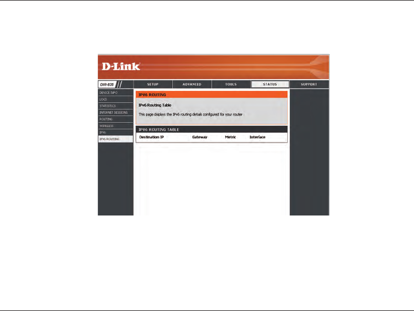
91D-Link DIR-835 User Manual
Section 3 - Conguration
IPV6 Routing
This page displays the IPV6 routing details congured for your router.
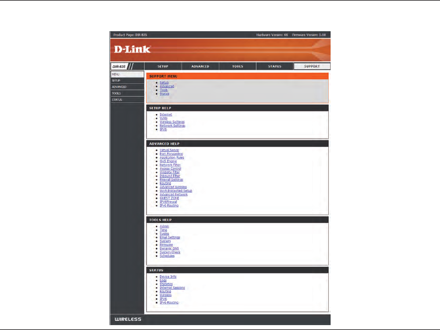
92D-Link DIR-835 User Manual
Section 3 - Conguration
Support

93D-Link DIR-835 User Manual
Section 4 - Security
Wireless Security
This section will show you the dierent levels of security you can use to protect your data from intruders. The
DIR-835 oers the following types of security:
• WPA2 (Wi-Fi Protected Access 2) • WPA2-PSK (Pre-Shared Key)
• WPA (Wi-Fi Protected Access) • WPA-PSK (Pre-Shared Key)
What is WPA?
WPA (Wi-Fi Protected Access), is a Wi-Fi standard that was designed to improve the security features of WEP (Wired Equivalent
Privacy).
The 2 major improvements over WEP:
• Improved data encryption through the Temporal Key Integrity Protocol (TKIP). TKIP scrambles the keys using a
hashing algorithm and, by adding an integrity-checking feature, ensures that the keys haven’t been tampered
with. WPA2 is based on 802.11i and uses Advanced Encryption Standard (AES) instead of TKIP.
• User authentication, which is generally missing in WEP, through the extensible authentication protocol (EAP).
WEP regulates access to a wireless network based on a computer’s hardware-specic MAC address, which is
relatively simple to be snied out and stolen. EAP is built on a more secure public-key encryption system to
ensure that only authorized network users can access the network.
WPA-PSK/WPA2-PSK uses a passphrase or key to authenticate your wireless connection. The key is an alpha-numeric password
between 8 and 63 characters long. The password can include symbols (!?*&_) and spaces. This key must be the exact same key
entered on your wireless router or access point.
WPA/WPA2 incorporates user authentication through the Extensible Authentication Protocol (EAP). EAP is built on a more
secure public key encryption system to ensure that only authorized network users can access the network.
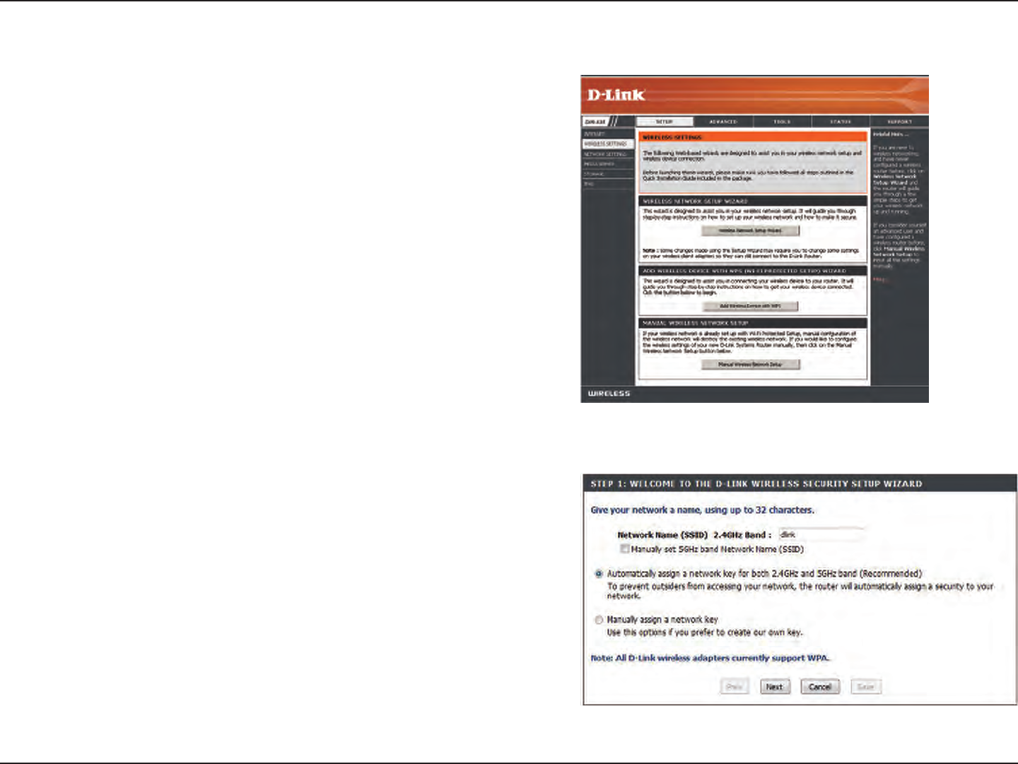
94D-Link DIR-835 User Manual
Section 4 - Security
Wireless Security Setup Wizard
To run the security wizard, click on Setup at the top and then click
Wireless Network Setup Wizard.
Check the Manually set 5GHz band Network Name... box to manually
set your desired wireless network name for the 5GHz band.
Type your desired wireless network name (SSID).
Automatically: Select this option to automatically generate
the router’s network key and click Next.
Manually: Select this option to manually enter your network
key and click Next.
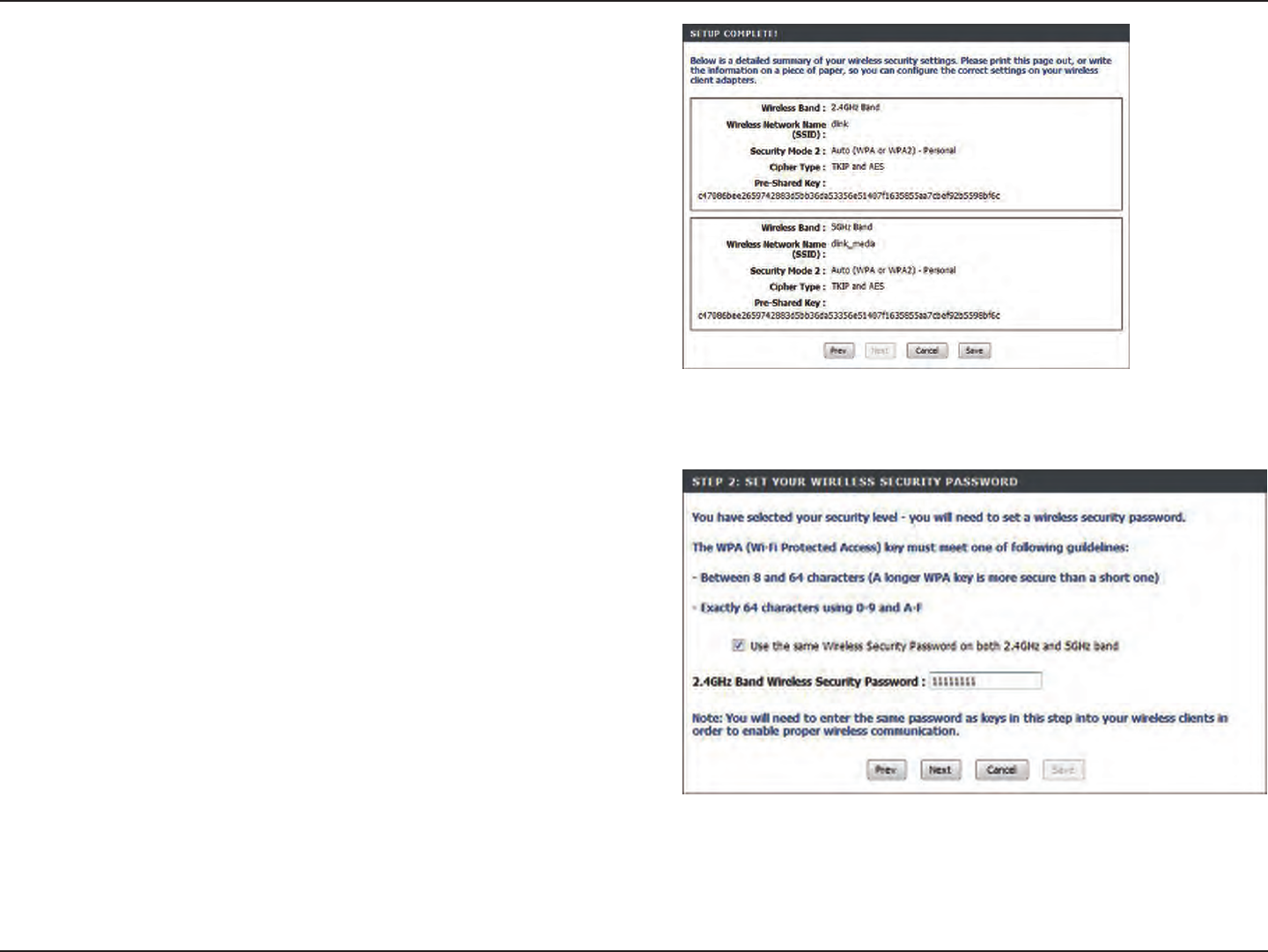
95D-Link DIR-835 User Manual
Section 4 - Security
If you selected Automatically, the summary window will display
your settings. Write down the security key and enter this on your
wireless clients. Click Save to save your settings.
If you selected Manually, the following screen will appear.
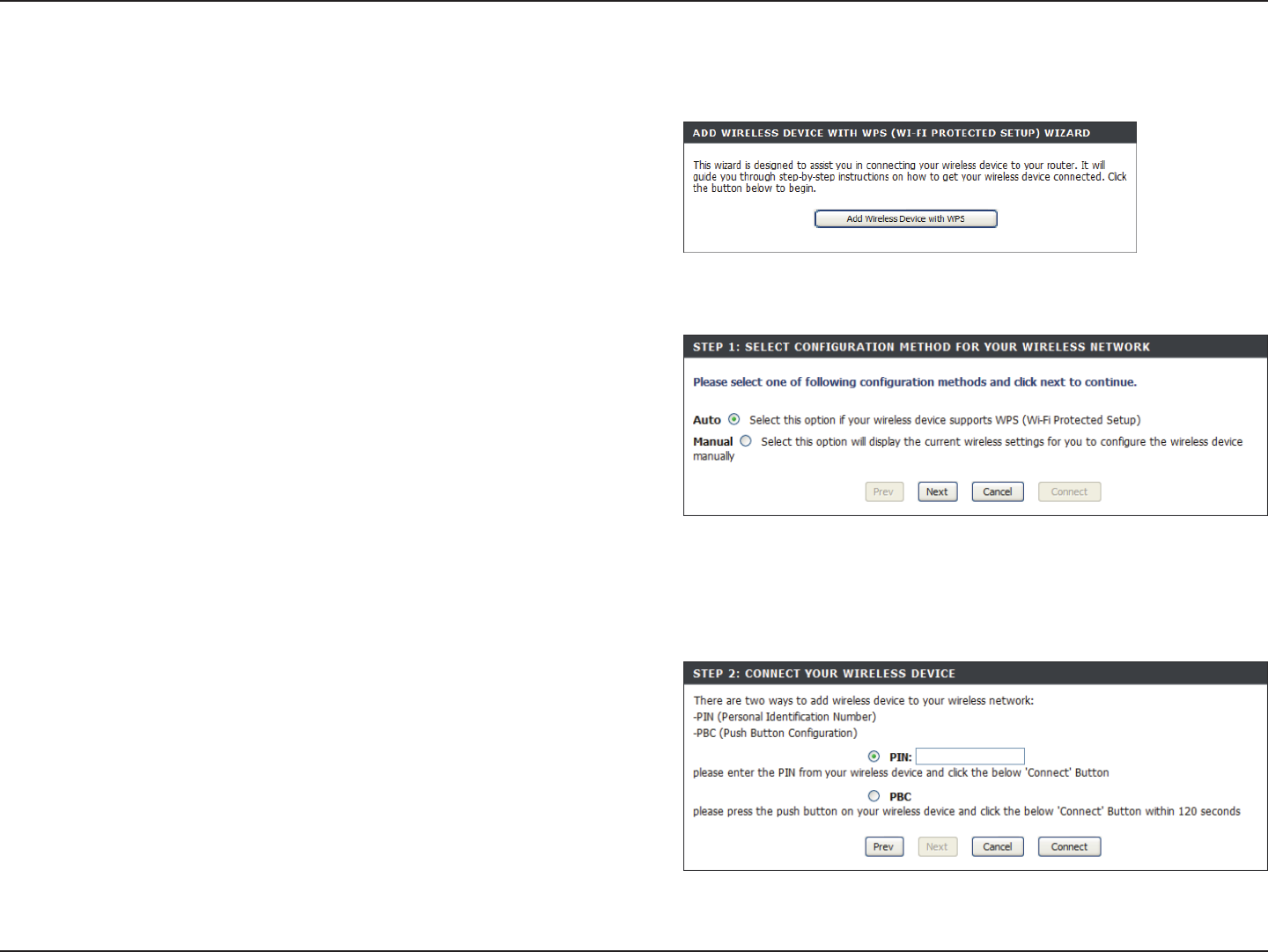
96D-Link DIR-835 User Manual
Section 4 - Security
From the Setup > Wireless Settings screen, click Add Wireless
Device with WPS.
Add Wireless Device with WPS Wizard
PIN: Select this option to use PIN method. In order to use this
method you must know the wireless client’s 8 digit PIN and click
Connect.
PBC: Select this option to use PBC (Push Button) method to add a
wireless client. Click Connect.
Select Auto to add a wireless client using WPS (Wi-Fi Protected
Setup). Once you select Auto and click Connect, you will have a
120 second time limit to apply the settings to your wireless client(s)
and successfully establish a connection.
If you select Manual, a settings summary screen will appear. Write
down the security key and enter this on your wireless clients.
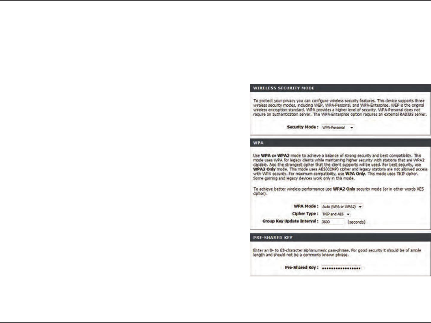
97D-Link DIR-835 User Manual
Section 4 - Security
Congure WPA-Personal (PSK)
It is recommended to enable encryption on your wireless router before your wireless network adapters. Please establish
wireless connectivity before enabling encryption. Your wireless signal may degrade when enabling encryption due to the
added overhead.
1. Log into the web-based conguration by opening a web browser and
entering the IP address of the router (192.168.0.1). Click on Setup and
then click Wireless Settings on the left side.
2. Next to Security Mode, select WPA-Personal.
3. Next to WPA Mode, select Auto, WPA2 Only, or WPA Only. Use Auto
if you have wireless clients using both WPA and WPA2.
4. Next to Cypher Type, select TKIP and AES, TKIP, or AES.
5. Next to Group Key Update Interval, enter the amount of time before
the group key used for broadcast and multicast data is changed (3600
is default).
6. Next to Pre-Shared Key, enter a key (passphrase). The key is entered as
a pass-phrase in ASCII format at both ends of the wireless connection.
The pass-phrase must be between 8-63 characters.
7. Click Save Settings to save your settings. If you are conguring the
router with a wireless adapter, you will lose connectivity until you enable WPA-PSK on your adapter and enter the same
passphrase as you did on the router.
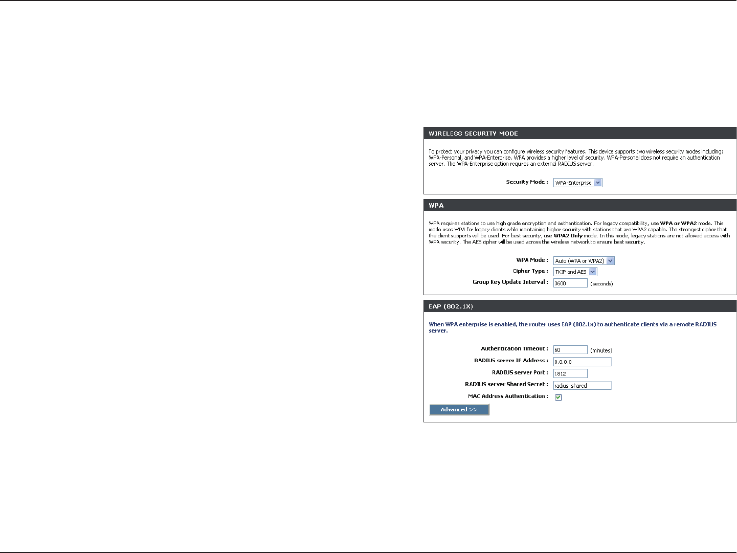
98D-Link DIR-835 User Manual
Section 4 - Security
It is recommended to enable encryption on your wireless router before your wireless network adapters. Please establish
wireless connectivity before enabling encryption. Your wireless signal may degrade when enabling encryption due to the
added overhead.
1. Log into the web-based conguration by opening a web browser
and entering the IP address of the router (192.168.0.1). Click on
Setup and then click Wireless Settings on the left side.
2. Next to Security Mode, select WPA-Enterprise.
3. Next to WPA Mode, select Auto, WPA2 Only, or WPA Only. Use Auto
if you have wireless clients using both WPA and WPA2.
4. Next to Cypher Type, select TKIP and AES, TKIP, or AES.
5. Next to Group Key Update Interval, enter the amount of time before
the group key used for broadcast and multicast data is changed
(3600 is default).
6. Next to Authentication Timeout, enter the amount of time before a
client is required to re-authenticate (60 minutes is default).
7. Next to RADIUS Server IP Address enter the IP Address of your RADIUS server.
Congure WPA-Enterprise (RADIUS)
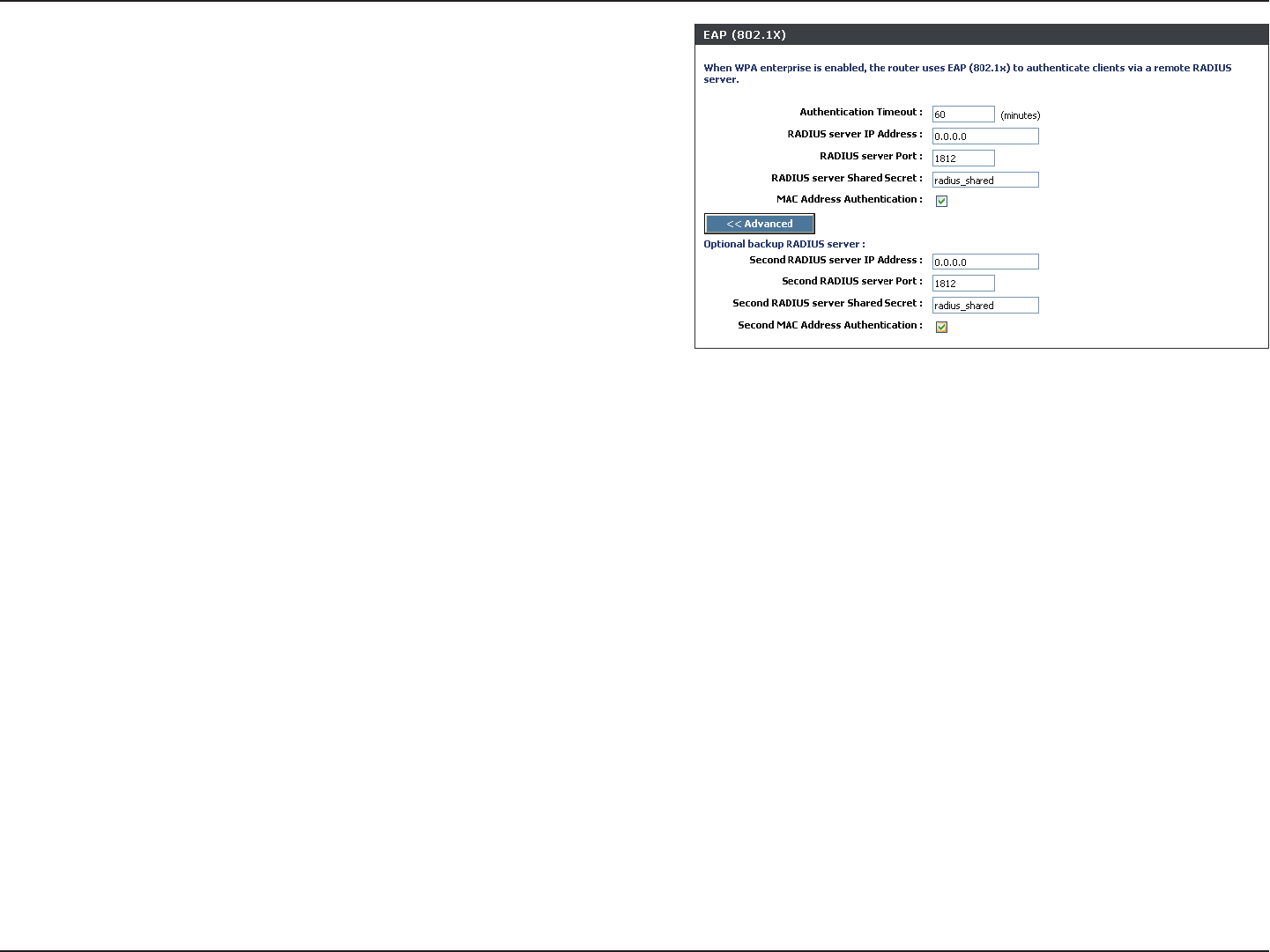
99D-Link DIR-835 User Manual
Section 4 - Security
8. Next to RADIUS Server Port, enter the port you are using with
your RADIUS server. 1812 is the default port.
9. Next to RADIUS Server Shared Secret, enter the security key.
10. If the MAC Address Authentication box is selected then the user
will need to connect from the same computer whenever logging
into the wireless network.
11. Click Advanced to enter settings for a secondary RADIUS
Server.
12. Click Apply Settings to save your settings.
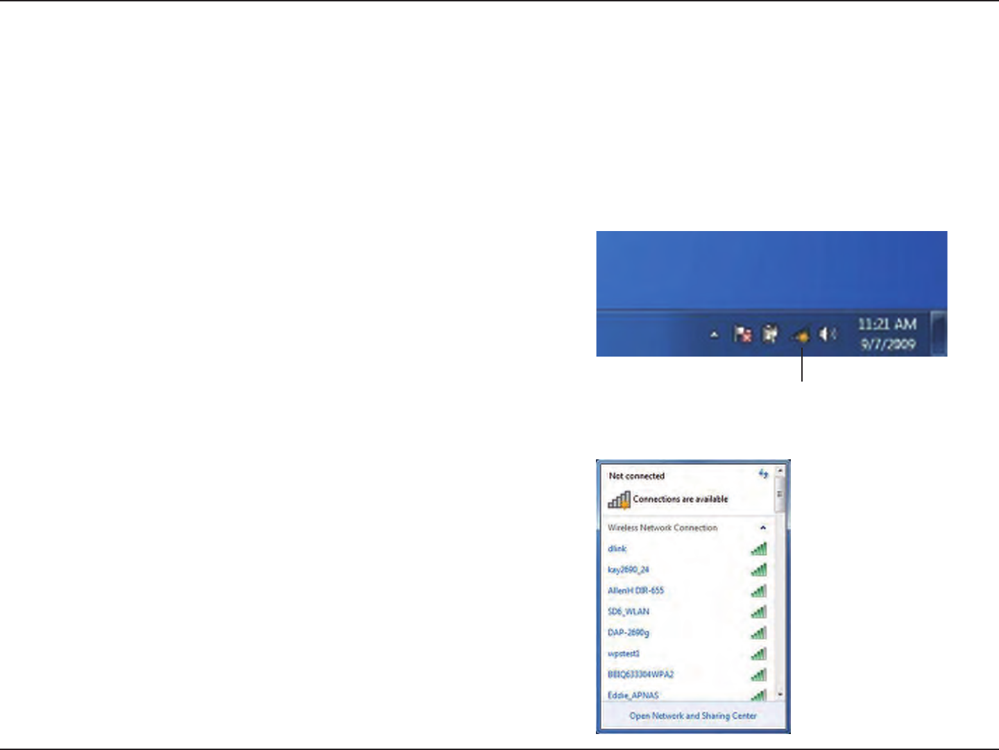
100D-Link DIR-835 User Manual
Section 4 - Security
Using Windows® 7
It is recommended to enable wireless security (WPA/WPA2) on your wireless router or access point before conguring your
wireless adapter. If you are joining an existing network, you will need to know the security key or passphrase being used.
1. Click on the wireless icon in your system tray (lower-right corner).
2. The utility will display any available wireless networks in your area.
Connect to a Wireless Network
Wireless Icon
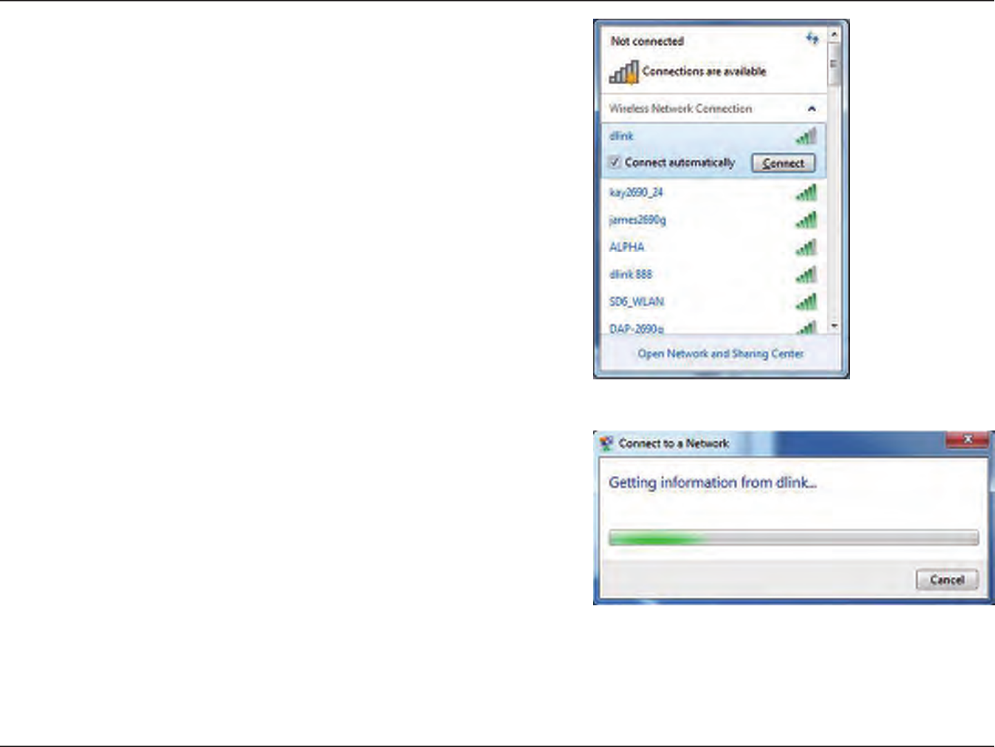
101D-Link DIR-835 User Manual
Section 4 - Security
3. Highlight the wireless network (SSID) you would like to connect to
and click the Connect button.
If you get a good signal but cannot access the Internet, check your
TCP/IP settings for your wireless adapter. Refer to the Networking
Basics section in this manual for more information.
4. The following window appears while your computer tries to
connect to the router.
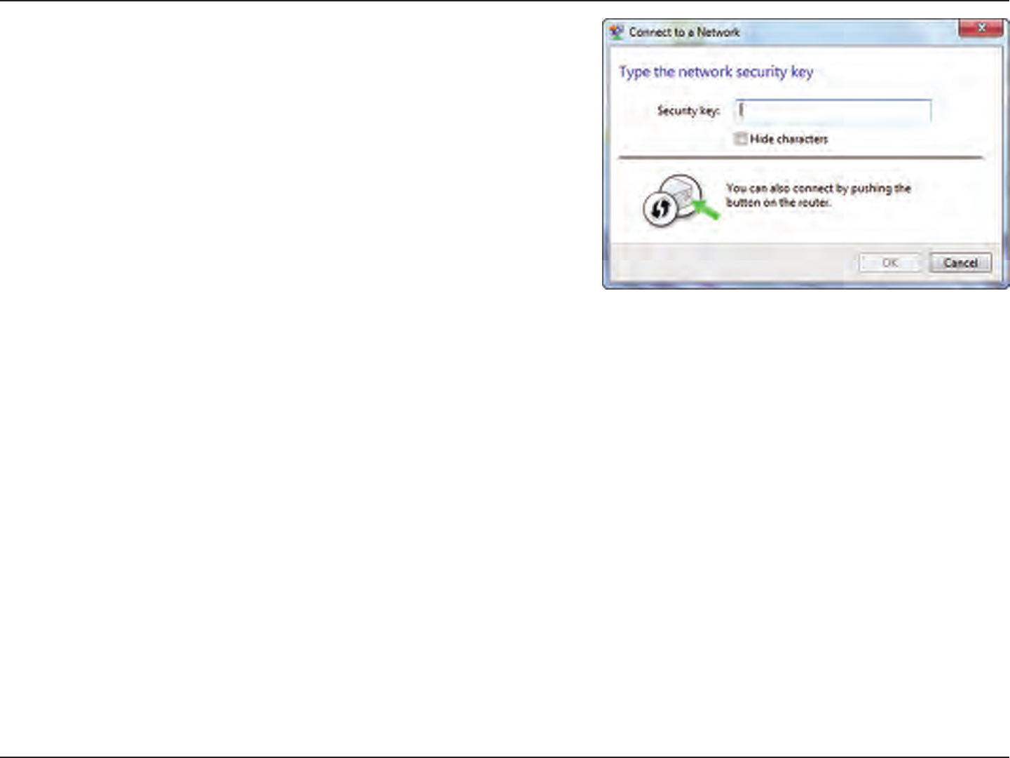
102D-Link DIR-835 User Manual
Section 4 - Security
5. Enter the same security key or passphrase that is on your router
and click Connect. You can also connect by pushing the WPS
button on the router.
It may take 20-30 seconds to connect to the wireless network. If the
connection fails, please verify that the security settings are correct.
The key or passphrase must be exactly the same as on the wireless
router.
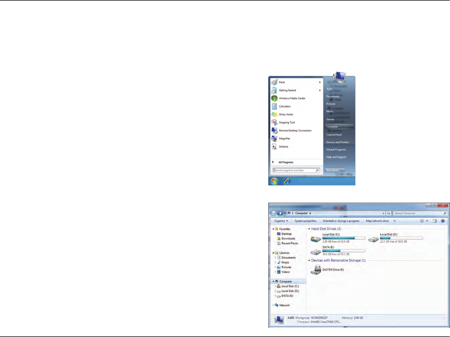
103D-Link DIR-835 User Manual
Section 4 - Security
Congure WPS
The WPS feature of the DIR-835 can be congured using Windows® 7. Carry out the following steps to use Windows® 7 to
congure the WPS feature:
1. Click the Start button and select Computer from the Start
menu.
2. Click the Network option.
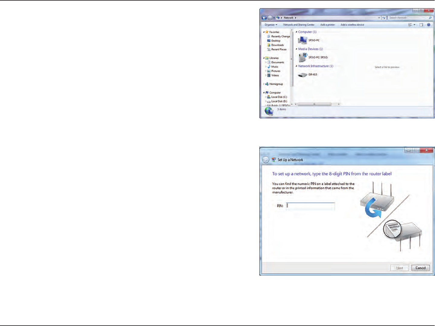
104D-Link DIR-835 User Manual
Section 4 - Security
3. Double-click the DIR-835.
4. Input the WPS PIN number (displayed in the WPS window on the
Router’s LCD screen or in the Setup > Wireless Setup menu in
the Router’s Web UI) and click Next.
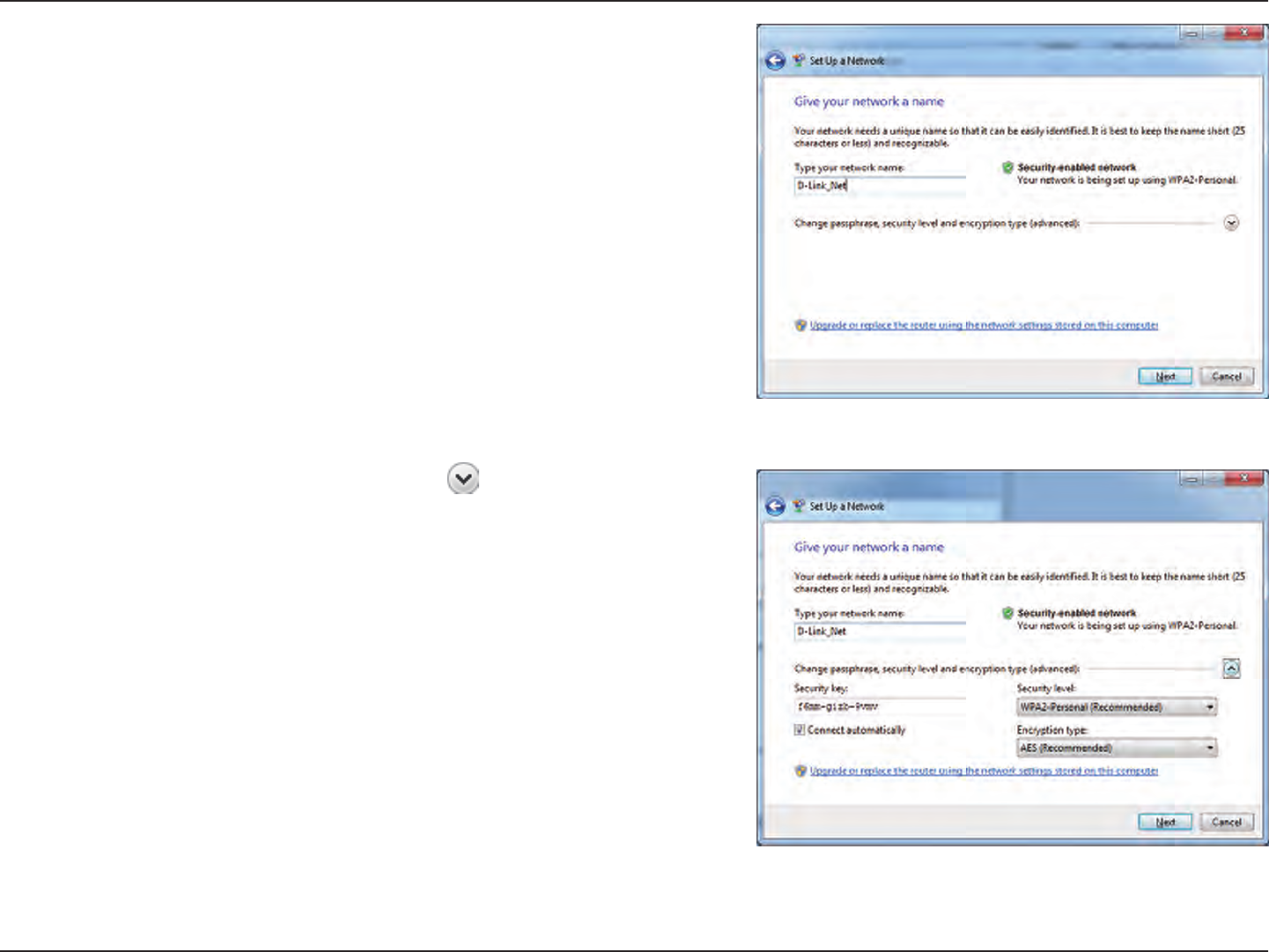
105D-Link DIR-835 User Manual
Section 4 - Security
5. Type a name to identify the network.
6. To congure advanced settings, click the icon.
Click Next to continue.
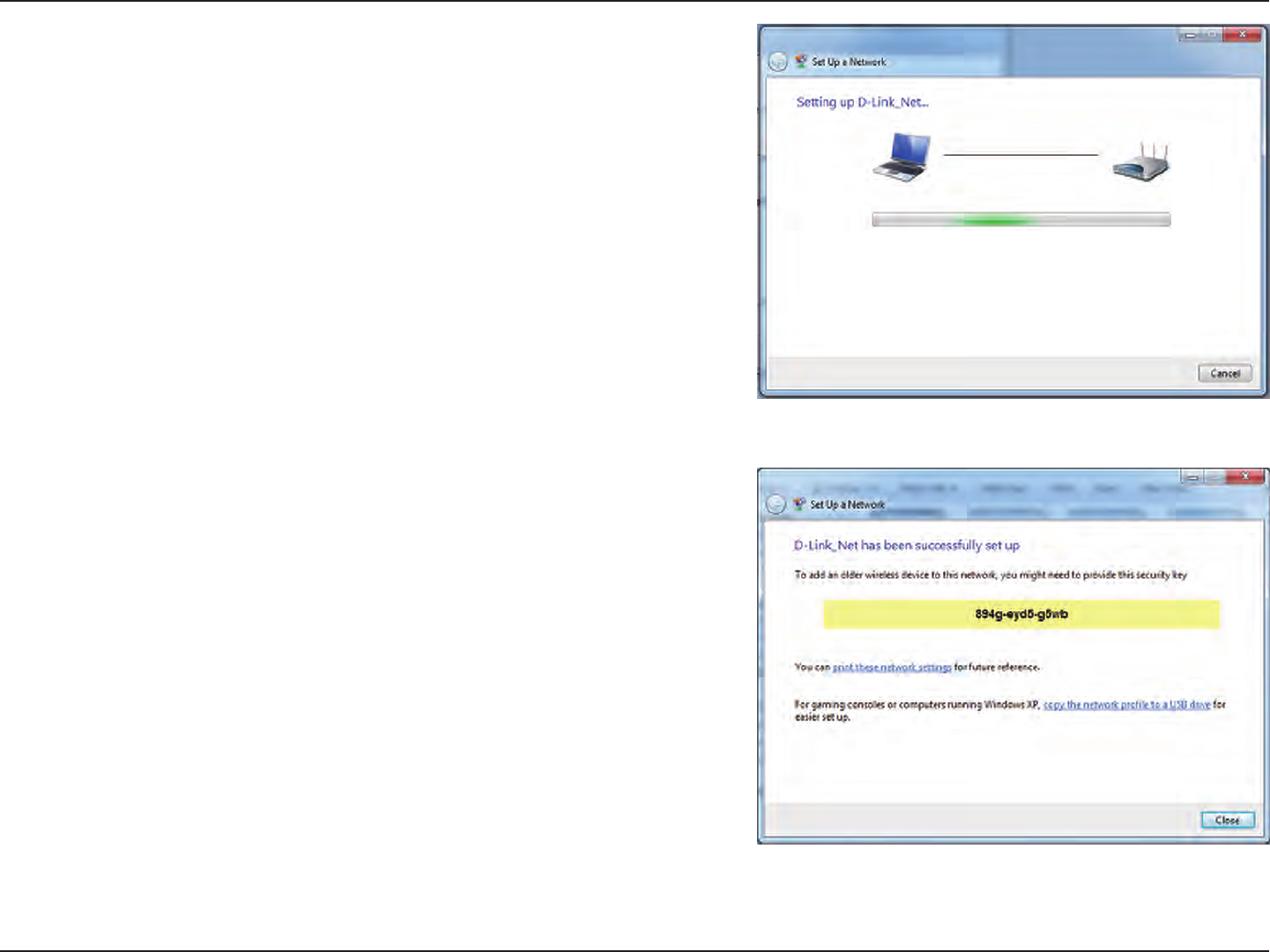
106D-Link DIR-835 User Manual
Section 4 - Security
7. The following window appears while the Router is being
congured.
Wait for the conguration to complete.
8. The following window informs you that WPS on the router has
been setup successfully.
Make a note of the security key as you may need to provide this
security key if adding an older wireless device to the network in
the future.
9. Click Close to complete WPS setup.
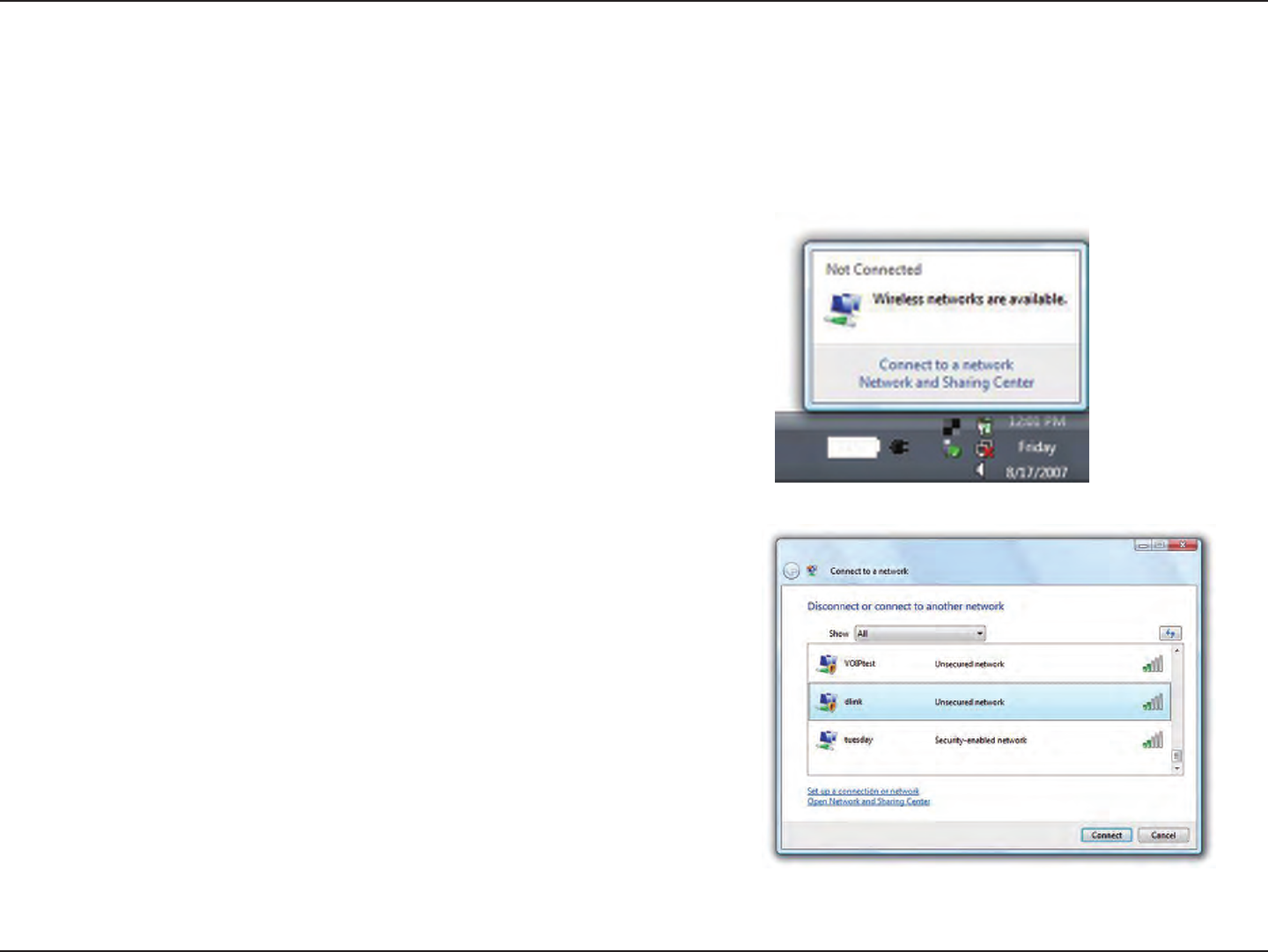
107D-Link DIR-835 User Manual
Section 5 - Connecting to a Wireless Network
Windows Vista®
Windows Vista® users may use the built-in wireless utility. If you are using another company’s utility or Windows® 2000, please
refer to the user manual of your wireless adapter for help with connecting to a wireless network. Most utilities will have a “site
survey” option similar to the Windows Vista® utility as seen below.
Right-click on the wireless computer icon in your system tray (lower-
right corner next to the time). Select Connect to a network.
If you receive the Wireless Networks Detected bubble, click on the
center of the bubble to access the utility.
or
The utility will display any available wireless networks in your area.
Click on a network (displayed using the SSID) and click the Connect
button.
If you get a good signal but cannot access the Internet, check you
TCP/IP settings for your wireless adapter. Refer to the Networking
Basics section in this manual for more information.
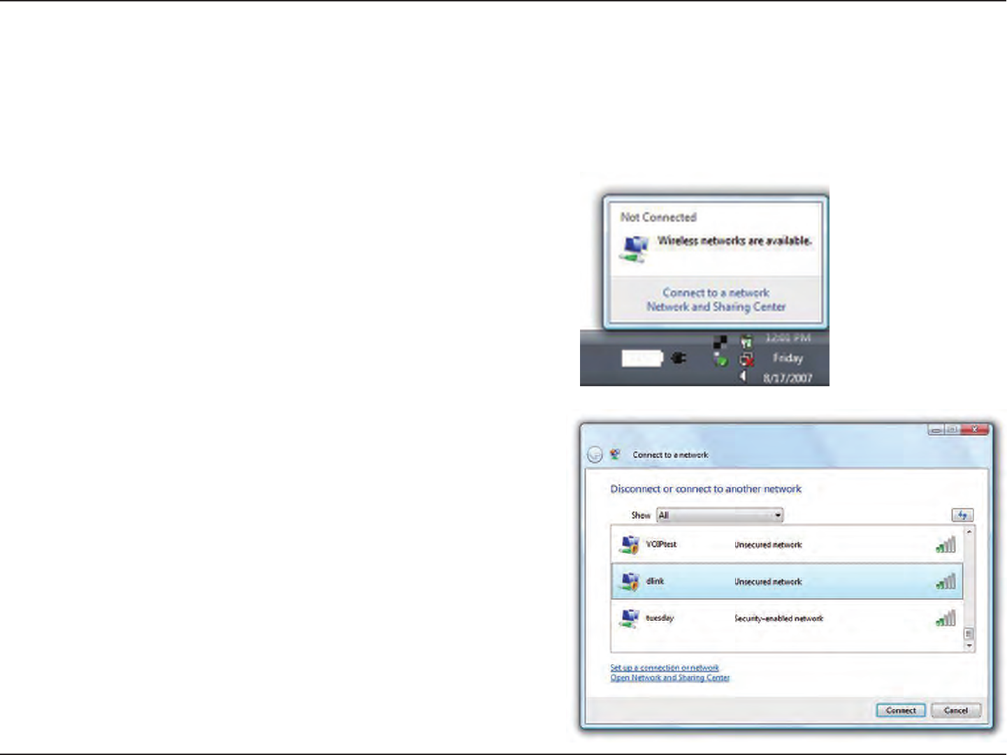
108D-Link DIR-835 User Manual
Section 5 - Connecting to a Wireless Network
Congure Wireless Security
It is recommended to enable wireless security (WPA/WPA2) on your wireless router or access point before conguring your
wireless adapter. If you are joining an existing network, you will need to know the security key or passphrase being used.
2. Highlight the wireless network (SSID) you would like to connect
to and click Connect.
1. Open the Windows Vista® Wireless Utility by right-clicking on the
wireless computer icon in your system tray (lower right corner of
screen). Select Connect to a network.
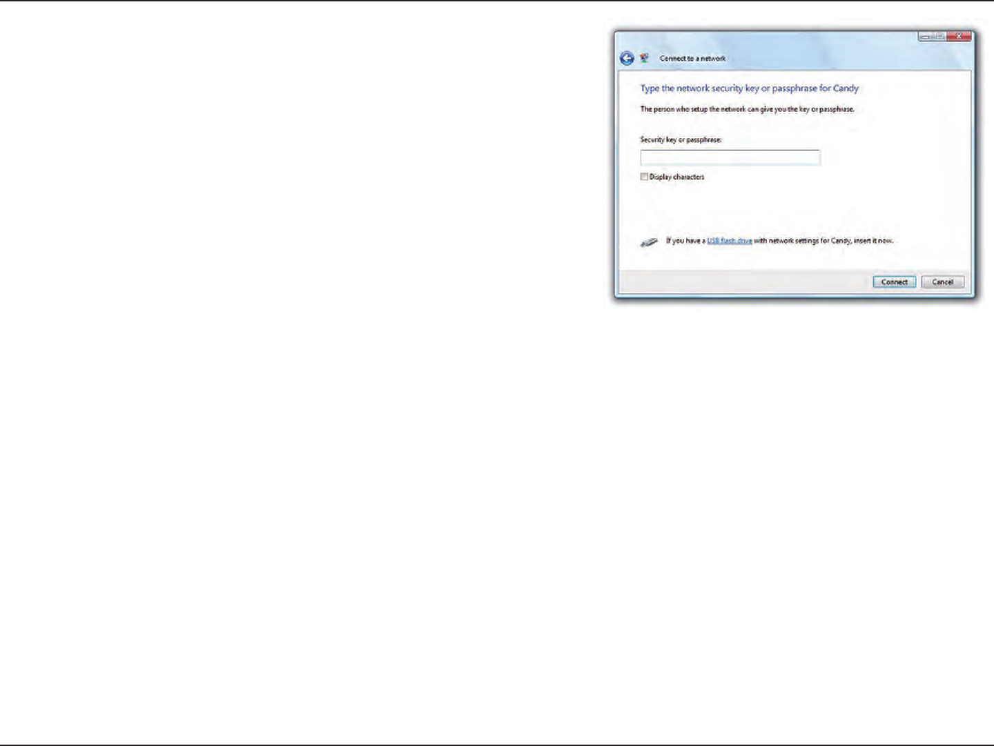
109D-Link DIR-835 User Manual
Section 5 - Connecting to a Wireless Network
3. Enter the same security key or passphrase that is on your router and
click Connect.
It may take 20-30 seconds to connect to the wireless network. If the
connection fails, please verify that the security settings are correct. The
key or passphrase must be exactly the same as on the wireless router.
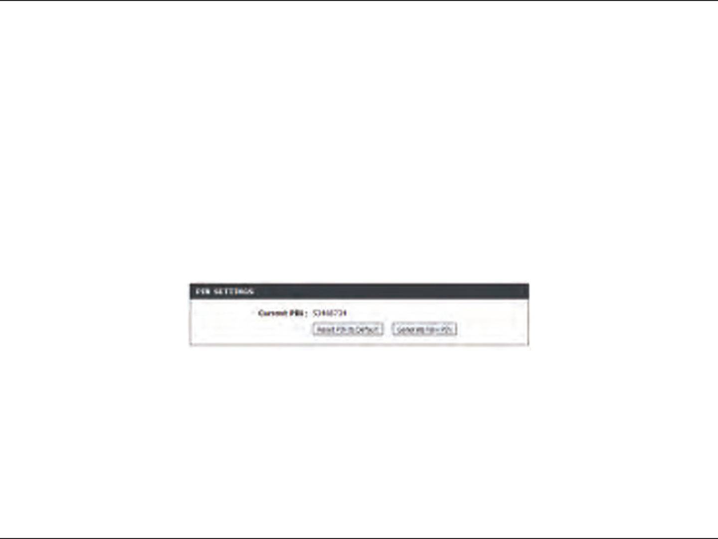
110D-Link DIR-835 User Manual
Section 5 - Connecting to a Wireless Network
Connect Using WCN 2.0 in Windows Vista®
The router supports Wi-Fi protection, referred to as WCN 2.0 in Windows Vista®. The following instructions for setting this up
depends on whether you are using Windows Vista® to congure the router or third party software.
When you rst set up the router, Wi-Fi protection is disabled and uncongured. To enjoy the benets of Wi-Fi protection, the
router must be both enabled and congured. There are three basic methods to accomplish this: use Windows Vista’s built-in
support for WCN 2.0, use software provided by a third party, or manually congure.
If you are running Windows Vista®, log into the router and click the Enable checkbox in the Basic > Wireless section. Use the
Current PIN that is displayed on the Advanced > Wi-Fi Protected Setup section or choose to click the Generate New PIN
button or Reset PIN to Default button.
For additional information, please refer to page 85.
If you are using third party software to set up Wi-Fi Protection, carefully follow the directions. When you are nished, proceed
to the next section to set up the newly-congured router.
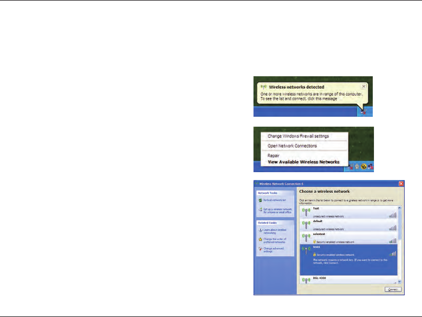
111D-Link DIR-835 User Manual
Section 5 - Connecting to a Wireless Network
Windows® XP
Windows® XP users may use the built-in wireless utility (Zero Conguration Utility). The following instructions are for Service
Pack 2 users. If you are using another company’s utility or Windows® 2000, please refer to the user manual of your wireless
adapter for help with connecting to a wireless network. Most utilities will have a “site survey” option similar to the Windows®
XP utility as seen below.
Right-click on the wireless computer icon in your system tray (lower-
right corner next to the time). Select View Available Wireless
Networks.
If you receive the Wireless Networks Detected bubble, click on the
center of the bubble to access the utility.
or
The utility will display any available wireless networks in your area.
Click on a network (displayed using the SSID) and click the Connect
button.
If you get a good signal but cannot access the Internet, check you
TCP/IP settings for your wireless adapter. Refer to the Networking
Basics section in this manual for more information.
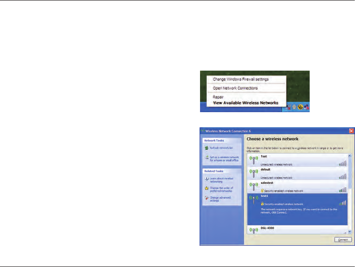
112D-Link DIR-835 User Manual
Section 5 - Connecting to a Wireless Network
Congure WPA-PSK
It is recommended to enable WPA on your wireless router or access point before conguring your wireless adapter. If you are
joining an existing network, you will need to know the WPA key being used.
2. Highlight the wireless network (SSID) you would like to
connect to and click Connect.
1. Open the Windows® XP Wireless Utility by right-clicking
on the wireless computer icon in your system tray
(lower-right corner of screen). Select View Available Wireless
Networks.
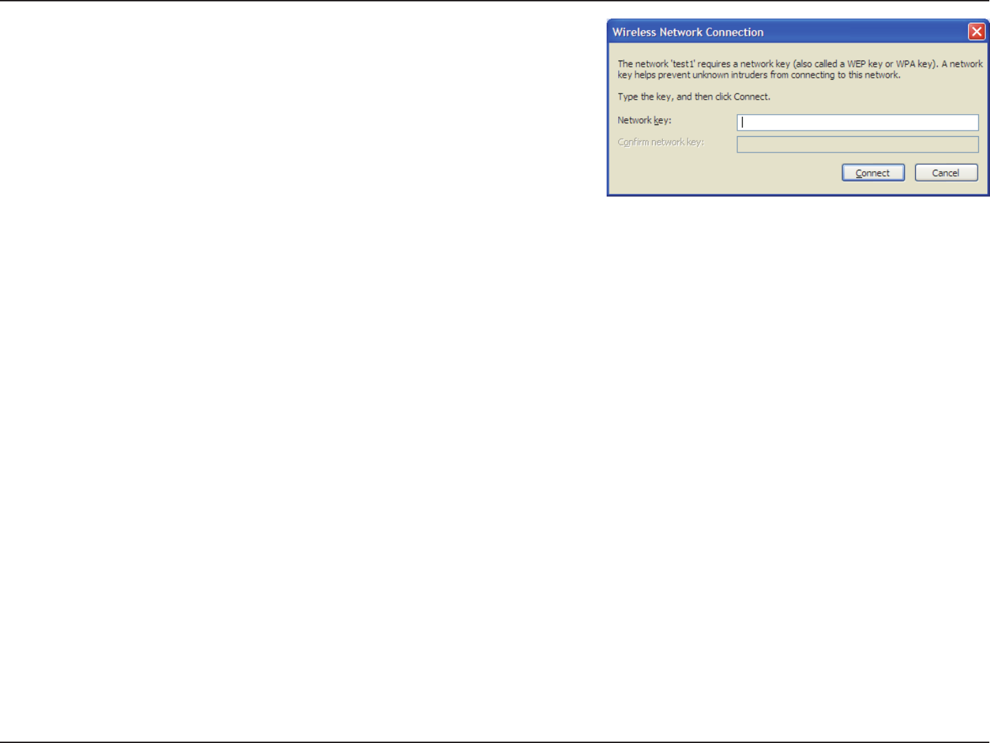
113D-Link DIR-835 User Manual
Section 5 - Connecting to a Wireless Network
3. The Wireless Network Connection box will appear. Enter the WPA-PSK
passphrase and click Connect.
It may take 20-30 seconds to connect to the wireless network. If the
connection fails, please verify that the WPA-PSK settings are correct. The
WPA-PSK passphrase must be exactly the same as on the wireless router.

114D-Link DIR-835 User Manual
Section 6 - Troubleshooting
Troubleshooting
This chapter provides solutions to problems that can occur during the installation and operation of the DIR-835. Read the
following descriptions if you are having problems. The examples below are illustrated in Windows® XP. If you have a dierent
operating system, the screenshots on your computer will look similar to the following examples.
1.Whycan’tIaccesstheweb-basedcongurationutility?
When entering the IP address of the D-Link router (192.168.0.1 for example), you are not connecting to a website nor do you
have to be connected to the Internet. The device has the utility built-in to a ROM chip in the device itself. Your computer must
be on the same IP subnet to connect to the web-based utility.
• Make sure you have an updated Java-enabled web browser. We recommend the following:
- Microsoft Internet Explorer® 6.0 and higher
- Mozilla Firefox 3.0 and higher
- Google™ Chrome 2.0 and higher
- Apple Safari 3.0 and higher
• Verify physical connectivity by checking for solid link lights on the device. If you do not get a solid link light, try using a
dierent cable or connect to a dierent port on the device if possible. If the computer is turned o, the link light may not be
on.
• Disable any Internet security software running on the computer. Software rewalls such as Zone Alarm, Black Ice, Sygate,
Norton Personal Firewall, and Windows® XP rewall may block access to the conguration pages. Check the help les included
with your rewall software for more information on disabling or conguring it.

115D-Link DIR-835 User Manual
Section 6 - Troubleshooting
• Congure your Internet settings:
• Go to Start > Settings > Control Panel. Double-click the Internet Options Icon. From the Security tab, click
the button to restore the settings to their defaults.
• Click the Connection tab and set the dial-up option to Never Dial a Connection. Click the LAN Settings button.
Make sure nothing is checked. Click OK.
• Go to the Advanced tab and click the button to restore these settings to their defaults. Click OK three times.
• Close your web browser (if open) and open it.
• Access the web management. Open your web browser and enter the IP address of your D-Link router in the address bar. This
should open the login page for your web management.
• If you still cannot access the conguration, unplug the power to the router for 10 seconds and plug back in. Wait about 30
seconds and try accessing the conguration. If you have multiple computers, try connecting using a dierent computer.
2.WhatcanIdoifIforgotmypassword?
If you forgot your password, you must reset your router. Unfortunately this process will change all your settings back to the
factory defaults.
To reset the router, locate the reset button (hole) on the rear panel of the unit. With the router powered on, use a paperclip
to hold the button down for 10 seconds. Release the button and the router will go through its reboot process. Wait about 30
seconds to access the router. The default IP address is 192.168.0.1. When logging in, the username is admin and leave the
password box empty.
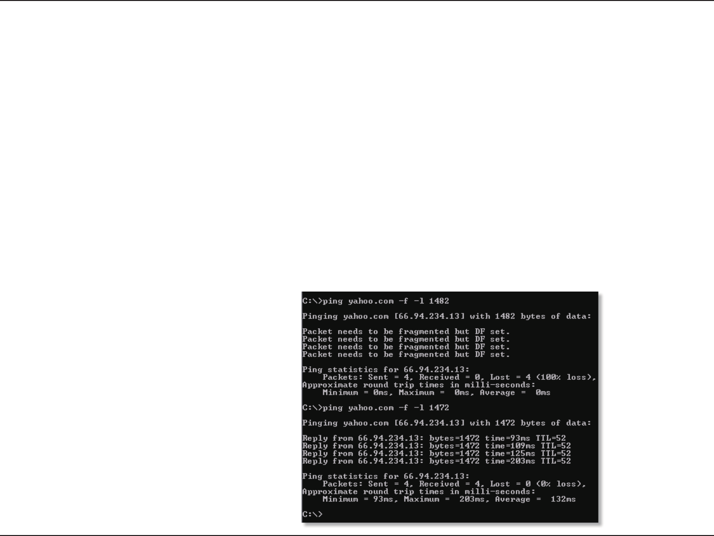
116D-Link DIR-835 User Manual
Section 6 - Troubleshooting
3.Whycan’tIconnecttocertainsitesorsendandreceiveemailswhenconnectingthroughmyrouter?
If you are having a problem sending or receiving email, or connecting to secure sites such as eBay, banking sites, and Hotmail,
we suggest lowering the MTU in increments of ten (Ex. 1492, 1482, 1472, etc).
Note: AOL DSL+ users must use MTU of 1400.
To nd the proper MTU Size, you’ll have to do a special ping of the destination you’re trying to go to. A destination could be
another computer, or a URL.
• Click on Start and then click Run.
• Windows® 95, 98, and Me users type in command (Windows® NT, 2000, XP, Vista®, and 7 users type in cmd) and
press Enter (or click OK).
• Once the window opens, you’ll need to do a special ping. Use the following syntax:
ping [url] [-f] [-l] [MTU value]
Example: ping yahoo.com -f -l 1472

117D-Link DIR-835 User Manual
Section 6 - Troubleshooting
You should start at 1472 and work your way down by 10 each time. Once you get a reply, go up by 2 until you get a
fragmented packet. Take that value and add 28 to the value to account for the various TCP/IP headers. For example, lets say
that 1452 was the proper value, the actual MTU size would be 1480, which is the optimum for the network we’re working with
(1452+28=1480).
Once you nd your MTU, you can now congure your router with the proper MTU size.
To change the MTU rate on your router follow the steps below:
• Open your browser, enter the IP address of your router (192.168.0.1) and click OK.
• Enter your username (admin) and password (blank by default). Click OK to enter the web conguration page
for the device.
• Click on Setup and then click Manual Congure.
• To change the MTU enter the number in the MTU eld and click Save Settings to save your settings.
• Test your email. If changing the MTU does not resolve the problem, continue changing the MTU in increments
of ten.

118D-Link DIR-835 User Manual
Appendix A - Wireless Basics
D-Link wireless products are based on industry standards to provide easy-to-use and compatible high-speed wireless
connectivity within your home, business or public access wireless networks. Strictly adhering to the IEEE standard, the D-Link
wireless family of products will allow you to securely access the data you want, when and where you want it. You will be able
to enjoy the freedom that wireless networking delivers.
A wireless local area network (WLAN) is a cellular computer network that transmits and receives data with radio signals instead of
wires. Wireless LANs are used increasingly in both home and oce environments, and public areas such as airports, coee shops
and universities. Innovative ways to utilize WLAN technology are helping people to work and communicate more eciently.
Increased mobility and the absence of cabling and other xed infrastructure have proven to be benecial for many users.
Wireless users can use the same applications they use on a wired network. Wireless adapter cards used on laptop and desktop
systems support the same protocols as Ethernet adapter cards.
Under many circumstances, it may be desirable for mobile network devices to link to a conventional Ethernet LAN in order to
use servers, printers or an Internet connection supplied through the wired LAN. A Wireless Router is a device used to provide
this link.
Wireless Basics

119D-Link DIR-835 User Manual
Appendix A - Wireless Basics
WhatisWireless?
Wireless or Wi-Fi technology is another way of connecting your computer to the network without using wires. Wi-Fi uses radio
frequency to connect wirelessly, so you have the freedom to connect computers anywhere in your home or oce network.
Why D-Link Wireless?
D-Link is the worldwide leader and award winning designer, developer, and manufacturer of networking products. D-Link
delivers the performance you need at a price you can aord. D-Link has all the products you need to build your network.
Howdoeswirelesswork?
Wireless works similar to how cordless phone work, through radio signals to transmit data from one point A to point B. But
wireless technology has restrictions as to how you can access the network. You must be within the wireless network range area
to be able to connect your computer. There are two dierent types of wireless networks Wireless Local Area Network (WLAN),
and Wireless Personal Area Network (WPAN).
Wireless Local Area Network (WLAN)
In a wireless local area network, a device called an Access Point (AP) connects computers to the network. The access point has
a small antenna attached to it, which allows it to transmit data back and forth over radio signals. With an indoor access point
as seen in the picture, the signal can travel up to 300 feet. With an outdoor access point the signal can reach out up to 30 miles
to serve places like manufacturing plants, industrial locations, college and high school campuses, airports, golf courses, and
many other outdoor venues.

120D-Link DIR-835 User Manual
Appendix A - Wireless Basics
Wireless Personal Area Network (WPAN)
Bluetooth is the industry standard wireless technology used for WPAN. Bluetooth devices in WPAN operate in a range up to
30 feet away.
Compared to WLAN the speed and wireless operation range are both less than WLAN, but in return it doesn’t use nearly as
much power which makes it ideal for personal devices, such as mobile phones, PDAs, headphones, laptops, speakers, and other
devices that operate on batteries.
Whouseswireless?
Wireless technology as become so popular in recent years that almost everyone is using it, whether it’s for home, oce, business,
D-Link has a wireless solution for it.
Home
• Gives everyone at home broadband access
• Surf the web, check email, instant message, etc.
• Gets rid of the cables around the house
• Simple and easy to use
Small Oce and Home Oce
• Stay on top of everything at home as you would at oce
• Remotely access your oce network from home
• Share Internet connection and printer with multiple computers
• No need to dedicate oce space

121D-Link DIR-835 User Manual
Appendix A - Wireless Basics
Whereiswirelessused?
Wireless technology is expanding everywhere not just at home or oce. People like the freedom of mobility and it’s becoming
so popular that more and more public facilities now provide wireless access to attract people. The wireless connection in public
places is usually called “hotspots”.
Using a D-Link Cardbus Adapter with your laptop, you can access the hotspot to connect to Internet from remote locations
like: Airports, Hotels, Coee Shops, Libraries, Restaurants, and Convention Centers.
Wireless network is easy to setup, but if you’re installing it for the rst time it could be quite a task not knowing where to start.
That’s why we’ve put together a few setup steps and tips to help you through the process of setting up a wireless network.
Tips
Here are a few things to keep in mind, when you install a wireless network.
Centralize your router or Access Point
Make sure you place the router/access point in a centralized location within your network for the best performance. Try to
place the router/access point as high as possible in the room, so the signal gets dispersed throughout your home. If you have
a two-story home, you may need a repeater to boost the signal to extend the range.
Eliminate Interference
Place home appliances such as cordless telephones, microwaves, and televisions as far away as possible from the router/
access point. This would signicantly reduce any interference that the appliances might cause since they operate on same
frequency.

122D-Link DIR-835 User Manual
Appendix A - Wireless Basics
Security
Don’t let you next-door neighbors or intruders connect to your wireless network. Secure your wireless network by turning on
the WPA or WEP security feature on the router. Refer to product manual for detail information on how to set it up.
There are basically two modes of networking:
• Infrastructure – All wireless clients will connect to an access point or wireless router.
• Ad-Hoc – Directly connecting to another computer, for peer-to-peer communication, using wireless network
adapters on each computer, such as two or more DIR-835 wireless network Cardbus adapters.
An Infrastructure network contains an Access Point or wireless router. All the wireless devices, or clients, will connect to the
wireless router or access point.
An Ad-Hoc network contains only clients, such as laptops with wireless cardbus adapters. All the adapters must be in Ad-Hoc
mode to communicate.
Wireless Modes
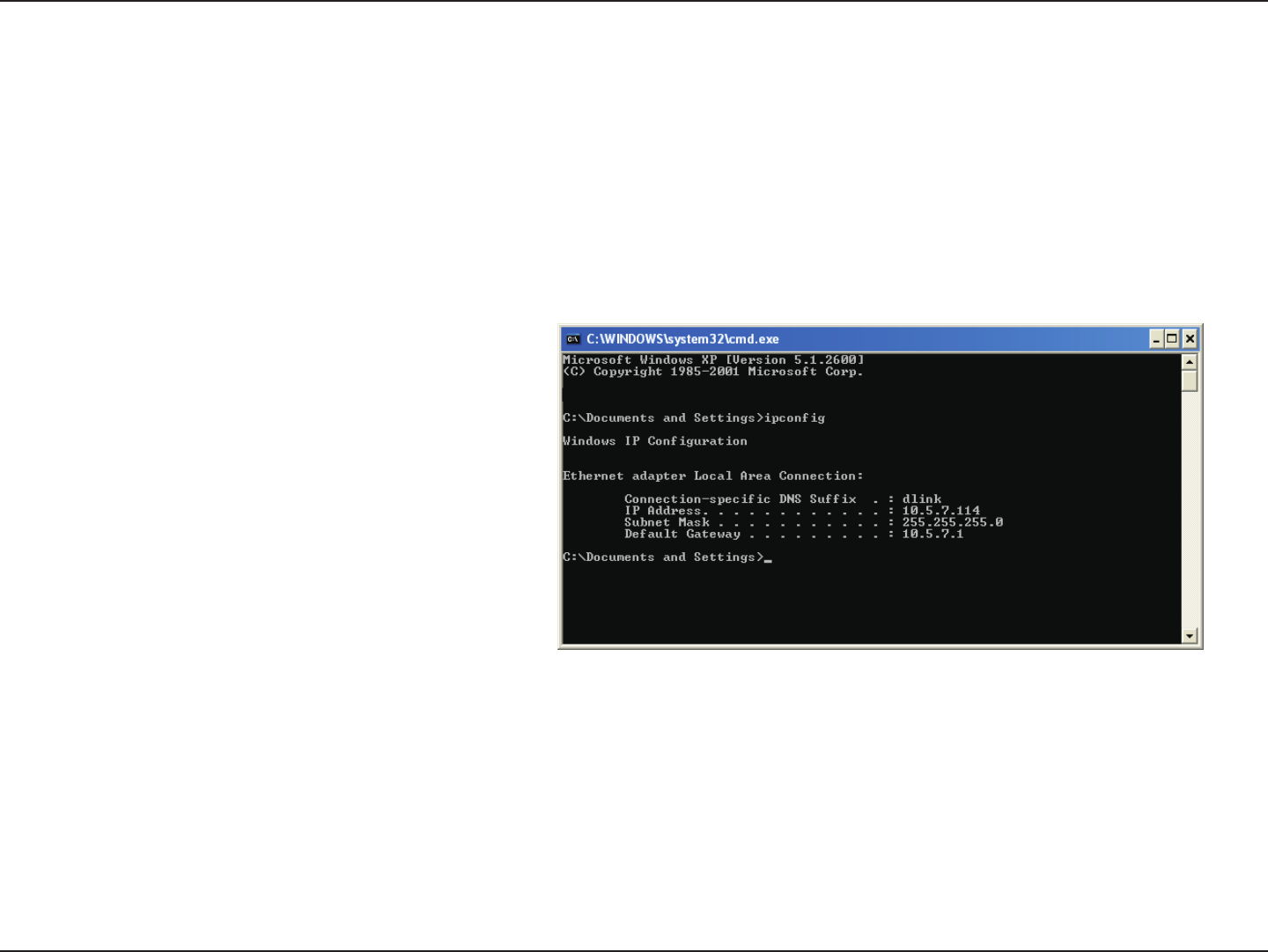
123D-Link DIR-835 User Manual
Appendix B - Networking Basics
Networking Basics
Check your IP address
After you install your new D-Link adapter, by default, the TCP/IP settings should be set to obtain an IP address from a DHCP
server (i.e. wireless router) automatically. To verify your IP address, please follow the steps below.
Click on Start > Run. In the run box type cmd and click OK. (Windows 7/Vista® users type cmd in the Start Search box.)
At the prompt, type ipcong and press Enter.
This will display the IP address, subnet mask, and the
default gateway of your adapter.
If the address is 0.0.0.0, check your adapter installation,
security settings, and the settings on your router.
Some rewall software programs may block a DHCP
request on newly installed adapters.
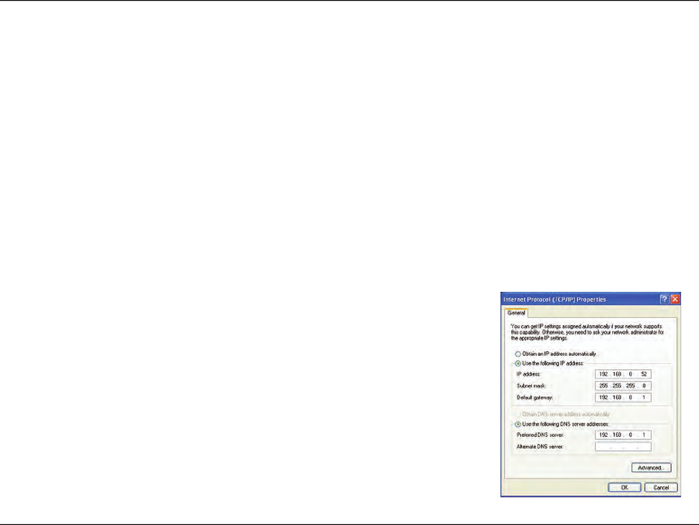
124D-Link DIR-835 User Manual
Appendix B - Networking Basics
Statically Assign an IP address
If you are not using a DHCP capable gateway/router, or you need to assign a static IP address, please follow the steps below:
Step 1
Windows® 7 - Click on Start > Control Panel > Network and Internet > Network and Sharing Center.
Windows Vista® - Click on Start > Control Panel > Network and Internet > Network and Sharing Center > Manage Network
Connections.
Windows® XP - Click on Start > Control Panel > Network Connections.
Windows® 2000 - From the desktop, right-click My Network Places > Properties.
Step 2
Right-click on the Local Area Connection which represents your network adapter and select Properties.
Step 3
Highlight InternetProtocol(TCP/IP) and click Properties.
Step 4
Click Use the following IP address and enter an IP address that is on the same subnet
as your network or the LAN IP address on your router.
Example: If the router´s LAN IP address is 192.168.0.1, make your IP address 192.168.0.X
where X is a number between 2 and 99. Make sure that the number you choose is not
in use on the network. Set the Default Gateway the same as the LAN IP address of your
router (I.E. 192.168.0.1).
Set Primary DNS the same as the LAN IP address of your router (192.168.0.1). The
Secondary DNS is not needed or you may enter a DNS server from your ISP.
Step 5
Click OK twice to save your settings.

125D-Link DIR-835 User Manual
Appendix C - Technical Specications
Technical Specications
Standards
• IEEE 802.11n
• IEEE 802.11g
• IEEE 802.11a
• IEEE 802.3
• IEEE 802.3u
• IEEE 802.3ab
Security
• WPA™ - Personal/Enterprise
• WPA2™ - Personal/Enterprise
Wireless Signal Rates1
IEEE802.11n2.4GHz(HT20/40):
• 144.4Mbps (300) · 130Mbps (270)
• 115.6Mbps (240) · 86.7Mbps (180)
• 72.2Mbps (150) · 65Mbps (135)
• 57.8Mbps (120) · 43.3Mbps (90)
• 28.9Mbps (60) · 21.7Mbps (45)
•14.4Mbps (30) · 7.2Mbps (15)
IEEE802.11n5GHz(HT20/40):
• 216Mbps (450) • 195Mbps (405)
•173.3Mbps (360) •144.4Mbps (300)
• 130.7Mbps (270) • 130Mbps (270)
•115.6Mbps (240) • 86.7Mbps (180)
•72.2Mbps (150) • 65Mbps (135)
•57.8Mbps (120) • 43.3Mbps (90)
•28.9Mbps (60) • 21.7Mbps (45)
•14.4Mbps (30) • 7.2Mbps (15)
IEEE 802.11g:
• 54Mbps • 48Mbps • 36Mbps
• 24Mbps • 18Mbps • 12Mbps
• 11Mbps • 9Mbps • 6Mbps
• 5.5Mbps • 2Mbps • 1Mbps
Frequency Range2 (North America)
• 2.412GHz to 2.462GHz (802.11g/n)
• 5.15GHz to 5.825GHz (802.11a/n)3
External Antenna Type
• Three (3) detachable Antennas
Operating Temperature
• 32°F to 131°F ( 0°C to 40°C)
Humidity
• 95% maximum (non-condensing)
Safety & Emissions
• FCC
• IC
Dimensions
• L = 7.6 inches
• W = 4.6 inches
• H = 1.2inches
Warranty
• 1 Year
1 Maximum wireless signal rate derived from IEEE Standard 802.11a, 802.11g, and 802.11n specications. Actual data throughput will vary. Network conditions and environmental factors, including
volume of network trac, building materials and construction, and network overhead, lower actual data throughput rate. Environmental factors will adversely aect wireless signal range.
2 Frequency Range varies depending on country’s regulation
3 The DIR-835 does not include 5.25-5.35GHz & 5.47-5.725GHz in some regions.

126D-Link DIR-835 User Manual
Appendix D - Contacting Technical Support
Contacting Technical Support
U.S. and Canadian customers can contact D-Link technical support through our web site or by phone.
Before you contact technical support, please have the following ready:
• Model number of the product (e.g. DIR-835)
• Hardware Revision (located on the label on the bottom of the router (e.g. rev A1))
• Serial Number (s/n number located on the label on the bottom of the router).
You can nd software updates and user documentation on the D-Link website as well as frequently asked questions and
answers to technical issues.
For customers within the United States:
Phone Support:
(877) 453-5465
Internet Support:
http://support.dlink.com
For customers within Canada:
Phone Support:
(800) 361-5265
Internet Support:
http://support.dlink.ca

127D-Link DIR-835 User Manual
Appendix E - Warranty
Warranty
Subject to the terms and conditions set forth herein, D-Link Systems, Inc. (“D-Link”) provides this Limited Warranty:
• Only to the person or entity that originally purchased the product from D-Link or its authorized reseller or distributor, and
• Only for products purchased and delivered within the fty states of the United States, the District of Columbia, U.S. Possessions
or Protectorates, U.S. Military Installations, or addresses with an APO or FPO.
Limited Warranty:
D-Link warrants that the hardware portion of the D-Link product described below (“Hardware”) will be free from material defects in workmanship
and materials under normal use from the date of original retail purchase of the product, for the period set forth below (“Warranty Period”), except
as otherwise stated herein.
• Hardware (excluding power supplies and fans): One (1) year
• Power supplies and fans: One (1) year
• Spare parts and spare kits: Ninety (90) days
The customer’s sole and exclusive remedy and the entire liability of D-Link and its suppliers under this Limited Warranty will be, at
D-Link’s option, to repair or replace the defective Hardware during the Warranty Period at no charge to the original owner or to refund the actual
purchase price paid. Any repair or replacement will be rendered by D-Link at an Authorized D-Link Service Oce. The replacement hardware
need not be new or have an identical make, model or part. D-Link may, at its option, replace the defective Hardware or any part thereof with any
reconditioned product that D-Link reasonably determines is substantially equivalent (or superior) in all material respects to the defective Hardware.
Repaired or replacement hardware will be warranted for the remainder of the original Warranty Period or ninety (90) days, whichever is longer,
and is subject to the same limitations and exclusions. If a material defect is incapable of correction, or if D-Link determines that it is not practical
to repair or replace the defective Hardware, the actual price paid by the original purchaser for the defective Hardware will be refunded by D-Link
upon return to D-Link of the defective Hardware. All Hardware or part thereof that is replaced by D-Link, or for which the purchase price is refunded,
shall become the property of D-Link upon replacement or refund.

128D-Link DIR-835 User Manual
Appendix E - Warranty
Limited Software Warranty:
D-Link warrants that the software portion of the product (“Software”) will substantially conform to D-Link’s then current functional specications
for the Software, as set forth in the applicable documentation, from the date of original retail purchase of the Software for a period of ninety (90)
days (“Software Warranty Period”), provided that the Software is properly installed on approved hardware and operated as contemplated in its
documentation. D-Link further warrants that, during the Software Warranty Period, the magnetic media on which D-Link delivers the Software will be
free of physical defects. The customer’s sole and exclusive remedy and the entire liability of D-Link and its suppliers under this Limited Warranty will
be, at D-Link’s option, to replace the non-conforming Software (or defective media) with software that substantially conforms to D-Link’s functional
specications for the Software or to refund the portion of the actual purchase price paid that is attributable to the Software. Except as otherwise
agreed by D-Link in writing, the replacement Software is provided only to the original licensee, and is subject to the terms and conditions of the
license granted by D-Link for the Software. Replacement Software will be warranted for the remainder of the original Warranty Period and is subject
to the same limitations and exclusions. If a material non-conformance is incapable of correction, or if D-Link determines in its sole discretion that it
is not practical to replace the non-conforming Software, the price paid by the original licensee for the non-conforming Software will be refunded by
D-Link; provided that the non-conforming Software (and all copies thereof) is rst returned to D-Link. The license granted respecting any Software
for which a refund is given automatically terminates.
Non-Applicability of Warranty:
The Limited Warranty provided hereunder for Hardware and Software portions of D-Link’s products will not be applied to and does not cover any
refurbished product and any product purchased through the inventory clearance or liquidation sale or other sales in which D-Link, the sellers, or
the liquidators expressly disclaim their warranty obligation pertaining to the product and in that case, the product is being sold “As-Is” without
any warranty whatsoever including, without limitation, the Limited Warranty as described herein, notwithstanding anything stated herein to the
contrary.
Submitting A Claim (USA):
The customer shall return the product to the original purchase point based on its return policy. In case the return policy period has expired and
the product is within warranty, the customer shall submit a claim to D-Link as outlined below:
• The customer must submit with the product as part of the claim a written description of the Hardware defect or Software
nonconformance in sucient detail to allow DLink to conrm the same, along with proof of purchase of the product (such as a
copy of the dated purchase invoice for the product) if the product is not registered.
• The customer must obtain a Case ID Number from D-Link Technical Support at 1-877-453-5465, who will attempt to assist the
customer in resolving any suspected defects with the product. If the product is considered defective, the customer must obtain
a Return Material Authorization (“RMA”) number by completing the RMA form and entering the assigned Case ID Number at
https://rma.dlink.com/.

129D-Link DIR-835 User Manual
Appendix E - Warranty
• After an RMA number is issued, the defective product must be packaged securely in the original or other suitable shipping package
to ensure that it will not be damaged in transit, and the RMA number must be prominently marked on the outside of the package.
Do not include any manuals or accessories in the shipping package. D-Link will only replace the defective portion of the product
and will not ship back any accessories.
• The customer is responsible for all in-bound shipping charges to D-Link. No Cash on Delivery (“COD”) is allowed. Products sent COD
will either be rejected by D-Link or become the property of D-Link. Products shall be fully insured by the customer and shipped
to D-Link Systems, Inc., 17595 Mt. Herrmann, Fountain Valley, CA 92708. D-Link will not be held responsible for any packages that
are lost in transit to D-Link. The repaired or replaced packages will be shipped to the customer via UPS Ground or any common
carrier selected by D-Link. Return shipping charges shall be prepaid by D-Link if you use an address in the United States, otherwise
we will ship the product to you freight collect. Expedited shipping is available upon request and provided shipping charges are
prepaid by the customer. D-Link may reject or return any product that is not packaged and shipped in strict compliance with the
foregoing requirements, or for which an RMA number is not visible from the outside of the package. The product owner agrees to
pay D-Link’s reasonable handling and return shipping charges for any product that is not packaged and shipped in accordance
with the foregoing requirements, or that is determined by D-Link not to be defective or non-conforming.
Submitting A Claim (Canada):
The customer shall return the product to the original purchase point based on its return policy. In case the return policy period has expired and
the product is within warranty, the customer shall submit a claim to D-Link as outlined below:
• Customers need to provide their receipt (proof of purchase) even if the product is registered. Without a receipt, no warranty service will
be done. The registration is not considered a proof of purchase.
• The customer must submit with the product as part of the claim a written description of the Hardware defect or Software nonconformance
in sucient detail to allow D-Link to conrm the same, along with proof of purchase of the product (such as a copy of the dated purchase
invoice for the product) if the product is not registered.
• The customer must obtain a Case ID Number from D-Link Technical Support at 1-800-361-5265, who will attempt to assist the customer
in resolving any suspected defects with the product. If the product is considered defective, the customer must obtain a Return Material
Authorization (“RMA”) number by completing the RMA form and entering the assigned Case ID Number at https://rma.dlink.ca/.
• After an RMA number is issued, the defective product must be packaged securely in the original or other suitable shipping package to
ensure that it will not be damaged in transit, and the RMA number must be prominently marked on the outside of the package. Do not
include any manuals or accessories in the shipping package. D-Link will only replace the defective portion of the product and will not ship
back any accessories.

130D-Link DIR-835 User Manual
Appendix E - Warranty
• The customer is responsible for all in-bound shipping charges to D-Link. No Cash on Delivery (“COD”) is allowed. Products sent COD will
be rejected by D-Link. Products shall be fully insured by the customer and shipped to D-Link Networks, Inc., 2525 Meadowvale Boulevard
Mississauga, Ontario, L5N 5S2 Canada. D-Link will not be held responsible for any packages that are lost in transit to D-Link. The repaired
or replaced packages will be shipped to the customer via Purolator Canada or any common carrier selected by D-Link. Return shipping
charges shall be prepaid by D-Link if you use an address in Canada, otherwise we will ship the product to you freight collect. Expedited
shipping is available upon request and provided shipping charges are prepaid by the customer. D-Link may reject or return any product
that is not packaged and shipped in strict compliance with the foregoing requirements, or for which an RMA number is not visible from
the outside of the package. The product owner agrees to pay D-Link’s reasonable handling and return shipping charges for any product
that is not packaged and shipped in accordance with the foregoing requirements, or that is determined by D-Link not to be defective or
non-conforming.
• RMA phone number: 1-800-361-5265 Hours of Operation: Monday-Friday, 9:00AM – 9:00PM EST
What Is Not Covered:
The Limited Warranty provided herein by D-Link does not cover:
Products that, in D-Link’s judgment, have been subjected to abuse, accident, alteration, modication, tampering, negligence, misuse, faulty installation,
lack of reasonable care, repair or service in any way that is not contemplated in the documentation for the product, or if the model or serial number
has been altered, tampered with, defaced or removed; Initial installation, installation and removal of the product for repair, and shipping costs;
Operational adjustments covered in the operating manual for the product, and normal maintenance; Damage that occurs in shipment, due to act
of God, failures due to power surge, and cosmetic damage; Any hardware, software, rmware or other products or services provided by anyone
other than D-Link; and Products that have been purchased from inventory clearance or liquidation sales or other sales in which D-Link, the sellers,
or the liquidators expressly disclaim their warranty obligation pertaining to the product.
While necessary maintenance or repairs on your Product can be performed by any company, we recommend that you use only an Authorized D-Link
Service Oce. Improper or incorrectly performed maintenance or repair voids this Limited Warranty.
Disclaimer of Other Warranties:
EXCEPT FOR THE LIMITED WARRANTY SPECIFIED HEREIN, THE PRODUCT IS PROVIDED “AS-IS” WITHOUT ANY WARRANTY OF ANY KIND WHATSOEVER
INCLUDING, WITHOUT LIMITATION, ANY WARRANTY OF MERCHANTABILITY, FITNESS FOR A PARTICULAR PURPOSE AND NONINFRINGEMENT.
IF ANY IMPLIED WARRANTY CANNOT BE DISCLAIMED IN ANY TERRITORY WHERE A PRODUCT IS SOLD, THE DURATION OF SUCH IMPLIED WARRANTY
SHALL BE LIMITED TO THE DURATION OF THE APPLICABLE WARRANTY PERIOD SET FORTH ABOVE. EXCEPT AS EXPRESSLY COVERED UNDER THE
LIMITED WARRANTY PROVIDED HEREIN, THE ENTIRE RISK AS TO THE QUALITY, SELECTION AND PERFORMANCE OF THE PRODUCT IS WITH THE
PURCHASER OF THE PRODUCT.

131D-Link DIR-835 User Manual
Appendix E - Warranty
Limitation of Liability:
TO THE MAXIMUM EXTENT PERMITTED BY LAW, D-LINK IS NOT LIABLE UNDER ANY CONTRACT, NEGLIGENCE, STRICT LIABILITY OR OTHER LEGAL
OR EQUITABLE THEORY FOR ANY LOSS OF USE OF THE PRODUCT, INCONVENIENCE OR DAMAGES OF ANY CHARACTER, WHETHER DIRECT, SPECIAL,
INCIDENTAL OR CONSEQUENTIAL (INCLUDING, BUT NOT LIMITED TO, DAMAGES FOR LOSS OF GOODWILL, LOSS OF REVENUE OR PROFIT, WORK
STOPPAGE, COMPUTER FAILURE OR MALFUNCTION, FAILURE OF OTHER EQUIPMENT OR COMPUTER PROGRAMS TO WHICH D-LINK’S PRODUCT
IS CONNECTED WITH, LOSS OF INFORMATION OR DATA CONTAINED IN, STORED ON, OR INTEGRATED WITH ANY PRODUCT RETURNED TO D-LINK
FOR WARRANTY SERVICE) RESULTING FROM THE USE OF THE PRODUCT, RELATING TO WARRANTY SERVICE, OR ARISING OUT OF ANY BREACH OF
THIS LIMITED WARRANTY, EVEN IF D-LINK HAS BEEN ADVISED OF THE POSSIBILITY OF SUCH DAMAGES. THE SOLE REMEDY FOR A BREACH OF
THE FOREGOING LIMITED WARRANTY IS REPAIR, REPLACEMENT OR REFUND OF THE DEFECTIVE OR NONCONFORMING PRODUCT. THE MAXIMUM
LIABILITY OF D-LINK UNDER THIS WARRANTY IS LIMITED TO THE PURCHASE PRICE OF THE PRODUCT COVERED BY THE WARRANTY. THE FOREGOING
EXPRESS WRITTEN WARRANTIES AND REMEDIES ARE EXCLUSIVE AND ARE IN LIEU OF ANY OTHER WARRANTIES OR REMEDIES, EXPRESS, IMPLIED
OR STATUTORY.
Governing Law:
This Limited Warranty shall be governed by the laws of the State of California. Some states do not allow exclusion or limitation of incidental or
consequential damages, or limitations on how long an implied warranty lasts, so the foregoing limitations and exclusions may not apply. This
Limited Warranty provides specic legal rights and you may also have other rights which vary from state to state.
Trademarks:
D-Link is a registered trademark of D-Link Corporation/D-Link Systems, Inc. Other trademarks or registered trademarks are the property of their
respective owners.
Copyright Statement:
No part of this publication or documentation accompanying this product may be reproduced in any form or by any means or used to make any
derivative such as translation, transformation, or adaptation without permission from D-Link Corporation/D-Link Systems, Inc., as stipulated by the
United States Copyright Act of 1976 and any amendments thereto. Contents are subject to change without prior notice.
Copyright ©2011 by D-Link Corporation/D-Link Systems, Inc. All rights reserved.
CE Mark Warning:
This is a Class B product. In a domestic environment, this product may cause radio interference, in which case the user may be required to take
adequate measures.

132D-Link DIR-835 User Manual
Appendix E - Warranty
Federal Communication Commission Interference Statement
This equipment has been tested and found to comply with the limits for a Class B digital device, pursuant to Part 15 of the FCC Rules. These limits are
designed to provide reasonable protection against harmful interference in a residential installation. This equipment generates, uses and can radiate
radio frequency energy and, if not installed and used in accordance with the instructions, may cause harmful interference to radio communications.
However, there is no guarantee that interference will not occur in a particular installation. If this equipment does cause harmful interference to radio
or television reception, which can be determined by turning the equipment o and on, the user is encouraged to try to correct the interference by
one of the following measures:
- Reorient or relocate the receiving antenna.
- Increase the separation between the equipment and receiver.
- Connect the equipment into an outlet on a circuit dierent from that to which the receiver is connected.
- Consult the dealer or an experienced radio/TV technician for help.
FCC Caution: Any changes or modications not expressly approved by the party responsible for compliance could void the user’s authority to
operate this equipment.
This device complies with Part 15 of the FCC Rules. Operation is subject to the following two conditions: (1) This device may not cause harmful
interference, and (2) this device must accept any interference received, including interference that may cause undesired operation.
Operations in the 5.15-5.25GHz band are restricted to indoor usage only.
IMPORTANT NOTICE:
FCC Radiation Exposure Statement:
This equipment complies with FCC radiation exposure limits set forth for an uncontrolled environment. This equipment should be installed and
operated with minimum distance 22cm between the radiator & your body.
This transmitter must not be co-located or operating in conjunction with any other antenna or transmitter.
The availability of some specic channels and/or operational frequency bands are country dependent and are rmware programmed at the factory
to match the intended destination. The rmware setting is not accessible by the end user.

133D-Link DIR-835 User Manual
Appendix E - Warranty
Industry Canada statement:
This device complies with RSS-210 of the Industry Canada Rules. Operation is subject to the following two conditions: (1) This device may not cause
harmful interference, and (2) this device must accept any interference received, including interference that may cause undesired operation.
IMPORTANT NOTE:
Radiation Exposure Statement:
This equipment complies with IC radiation exposure limits set forth for an uncontrolled environment. This equipment should be installed and
operated with minimum distance 22cm between the radiator & your body.
(i) the device for operation in the band 5150-5250 MHz is only for indoor use to reduce the potential for harmful interference to co-channel mobile
satellite systems;
(ii) high-power radars are allocated as primary users (i.e. priority users) of the bands 5250-5350 MHz and 5650-5850 MHz and that these radars could
cause interference and/or damage to LE-LAN devices.
This device has been designed to operate with an antenna having a maximum gain of [2] dB. Antenna having a higher gain is strictly prohibited
per regulations of Industry Canada. The required antenna impedance is 50 ohms.
Under Industry Canada regulations, this radio transmitter may only operate using an antenna of a type and maximum (or lesser) gain approved for
the transmitter by Industry Canada. To reduce potential radio interference to other users, the antenna type and its gain should be so chosen that
the equivalent isotropically radiated power (e.i.r.p.) is not more than that necessary for successful communication.
This radio transmitter (IC: 4216A-IR835A1/ Model: DIR-835A1) has been approved by Industry Canada to operate with the antenna types listed
below with the maximum permissible gain and required antenna impedance for each antenna type indicated. Antenna types not included in this
list, having a gain greater than the maximum gain indicated for that type, are strictly prohibited for use with this device.
Ce dispositif est conforme à la norme CNR-210 d’Industrie Canada applicable aux appareils radio exempts de licence. Son fonctionnement est sujet
aux deux conditions suivantes: (1) le dispositif ne doit pas produire de brouillage préjudiciable, et (2) ce dispositif doit accepter tout brouillage reçu,
y compris un brouillage susceptible de provoquer un fonctionnement indésirable.

134D-Link DIR-835 User Manual
Appendix E - Warranty
NOTE IMPORTANTE:
Déclaration d’exposition aux radiations:
Cet équipement est conforme aux limites d’exposition aux rayonnements IC établies pour un environnement non contrôlé. Cet équipement doit
être installé et utilisé avec un minimum de 22cm de distance entre la source de rayonnement et votre corps.
(i) les dispositifs fonctionnant dans la bande 5 150-5 250 MHz sont réservés uniquement pour une utilisation à l’intérieur an de réduire les risques
de brouillage préjudiciable aux systèmes de satellites mobiles utilisant les mêmes canaux;
(ii) De plus, les utilisateurs devraient aussi être avisés que les utilisateurs de radars de haute puissance sont désignés utilisateurs principaux (c.-à-d.,
qu’ils ont la priorité) pour les bandes 5 250-5 350 MHz et 5 650-5 850 MHz et que ces radars pourraient causer du brouillage et/ou des dommages
aux dispositifs LAN-EL.
Ce dispositif a été conçu pour fonctionner avec une antenne ayant un gain maximal de dB [3x]. Une antenne à gain plus élevé est strictement
interdite par les règlements d’Industrie Canada. L’impédance d’antenne requise est de 50 ohms.
Conformément à la réglementation d’Industrie Canada, le présent émetteur radio peutfonctionner avec une antenne d’un type et d’un gain maximal
(ou inférieur) approuvé pourl’émetteur par Industrie Canada. Dans le but de réduire les risques de brouillage radioélectriqueà l’intention des autres
utilisateurs, il faut choisir le type d’antenne et son gain de sorte que lapuissance isotrope rayonnée équivalente (p.i.r.e.) ne dépasse pas l’intensité
nécessaire àl’établissement d’une communication satisfaisante.
Le présent émetteur radio (IC: 4216A-IR835A1 / Modèle: DIR-835A1) a été approuvé par Industrie Canada pour fonctionner avec les types d’antenne
énumérés ci-dessous et ayant un gain admissible maximal et l’impédance requise pour chaque type d’antenne. Les types d’antenne non inclus dans
cette liste, ou dont le gain est supérieur au gain maximal indiqué, sont strictement interdits pour l’exploitation de l’émetteur.
Antenna information: dipole / 2dBi (Brand: D-Link / Manufacturer: Wha Yu)

135D-Link DIR-835 User Manual
Appendix F - Registration
Version 1.0
October 12, 2011
Product registration is entirely voluntary and failure to complete or return this form will not diminish your warranty rights.
Registration