D Link SR1000NA1 SMB Wireless N Gigabit VPN Router User Manual TF1 DSR 1 0 0 UM 0002
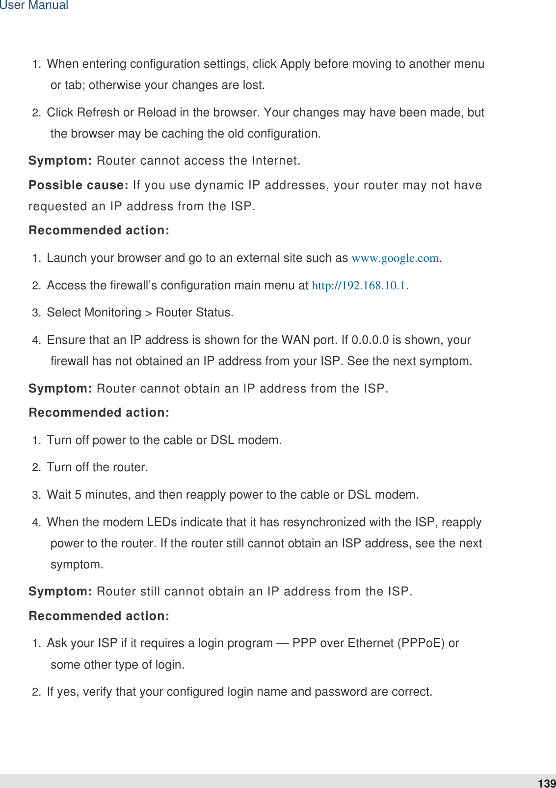
D Link Corporation SMB Wireless N Gigabit VPN Router TF1 DSR 1 0 0 UM 0002
UserManual.wiki
>
D Link
>
SR1000NA1 User Manual
>
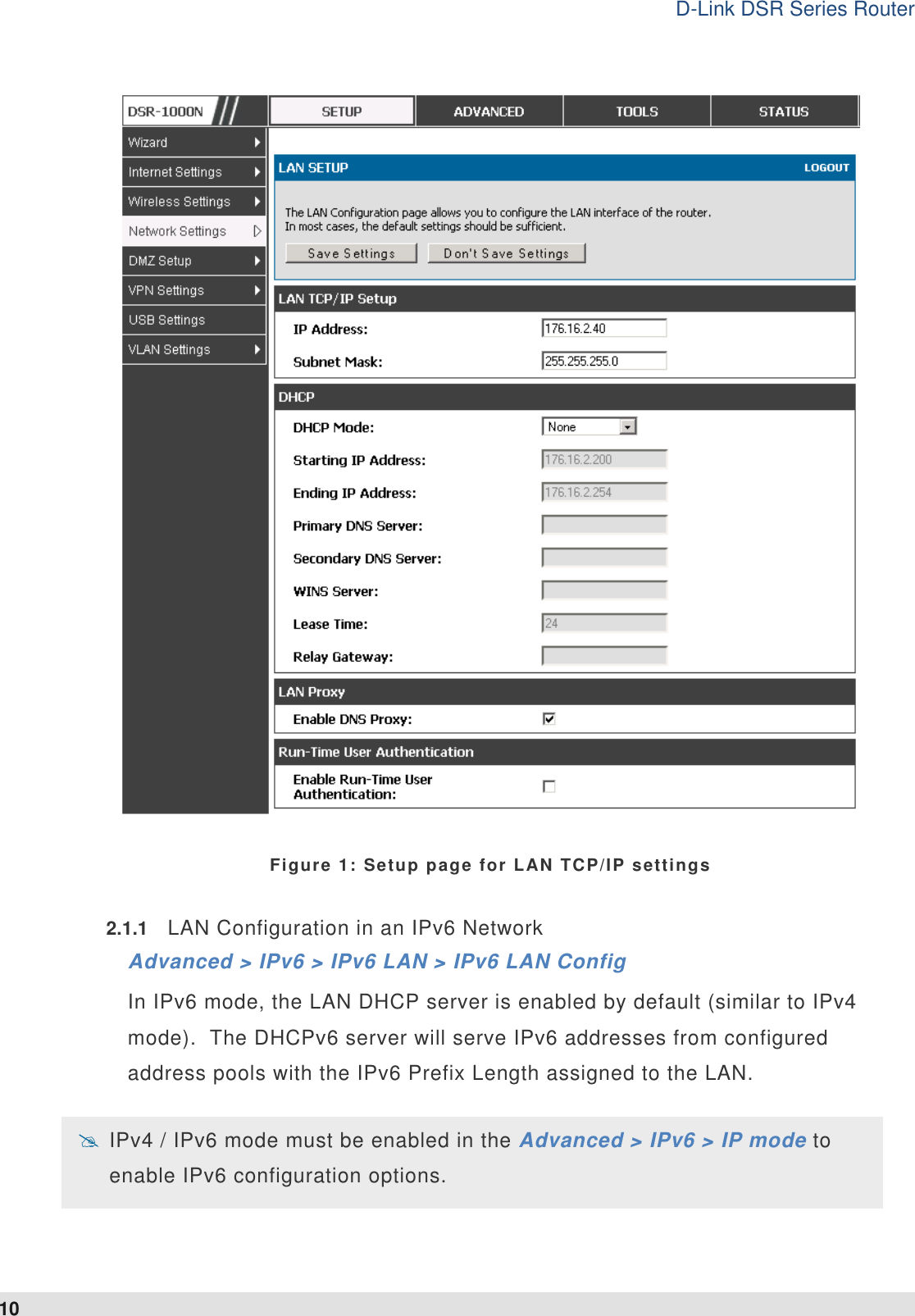
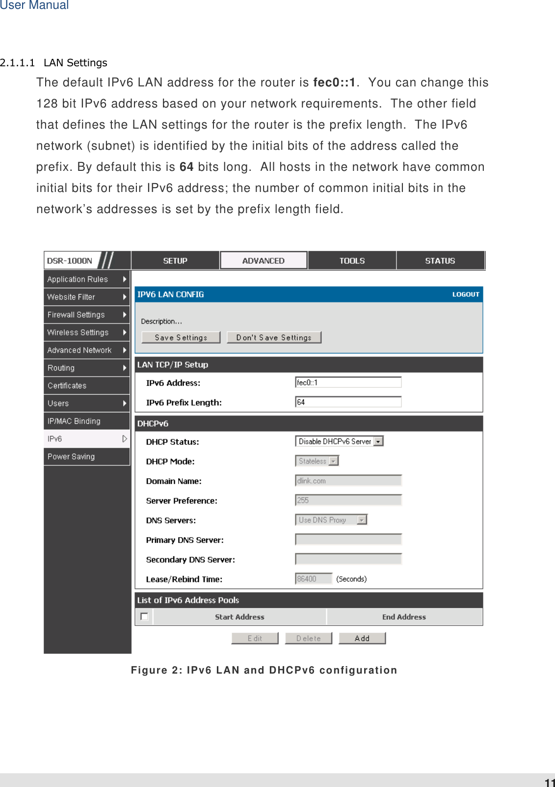
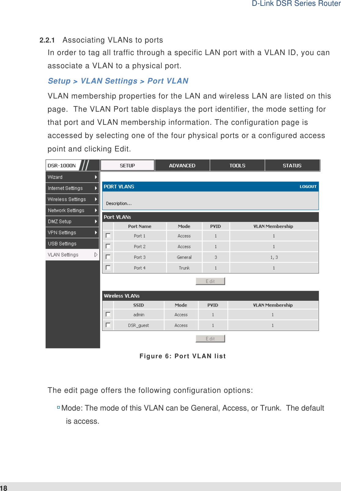
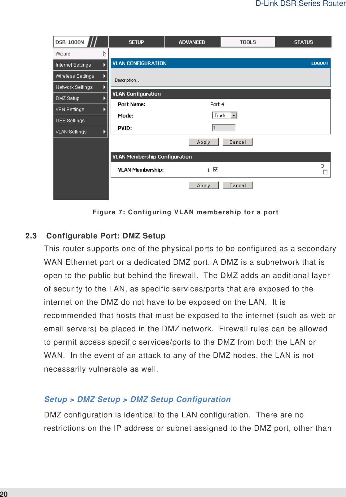
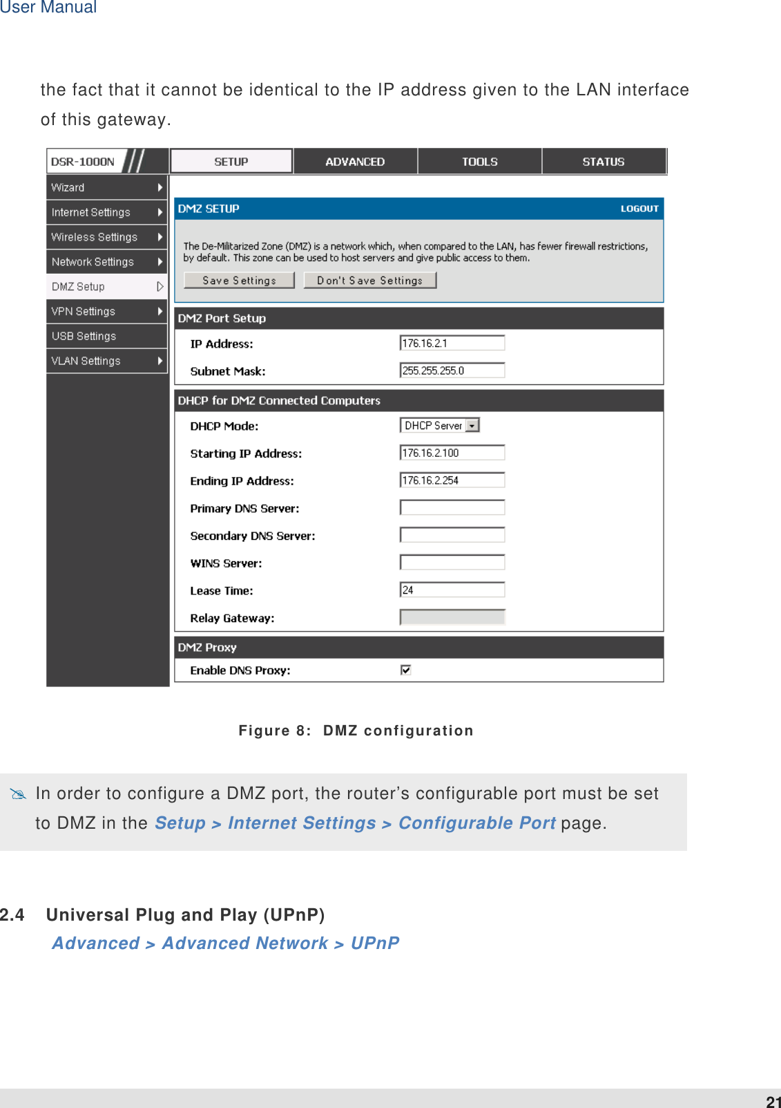
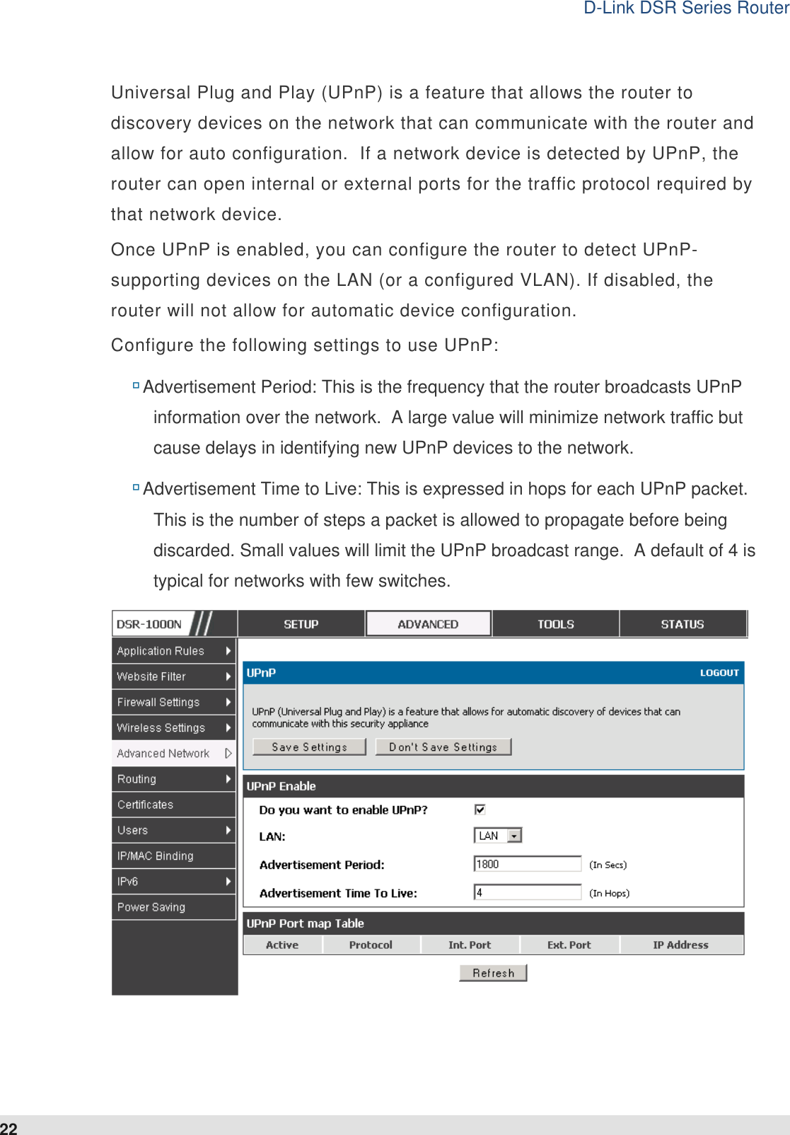
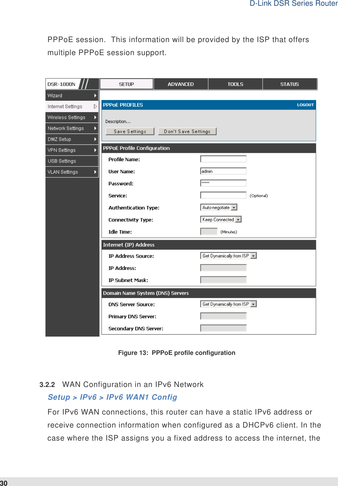
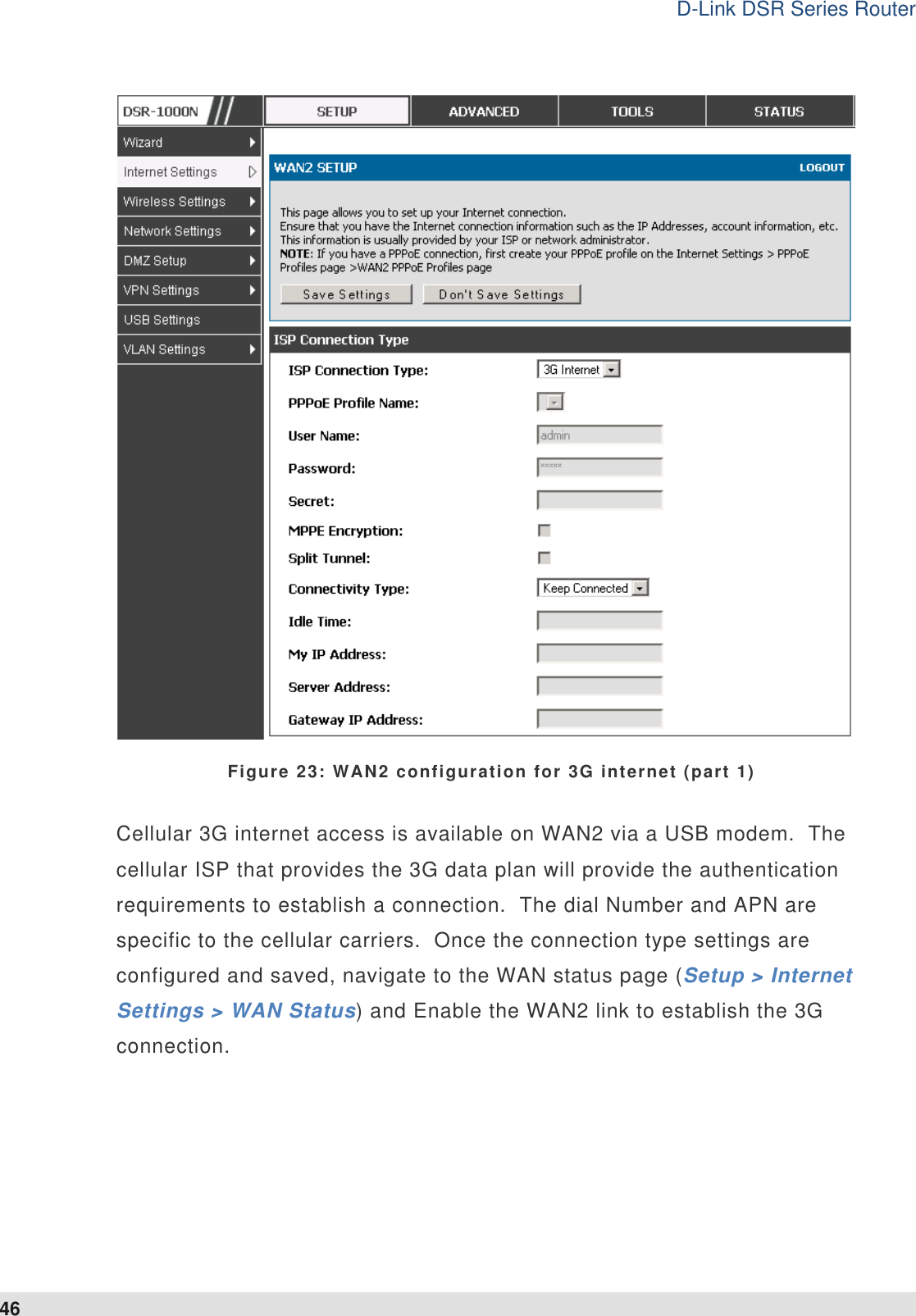
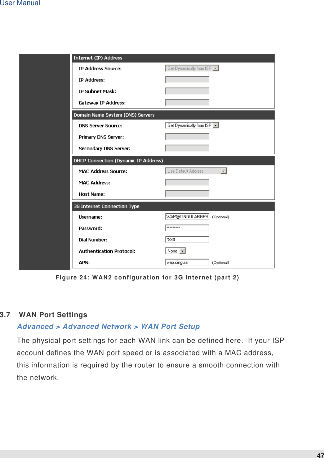
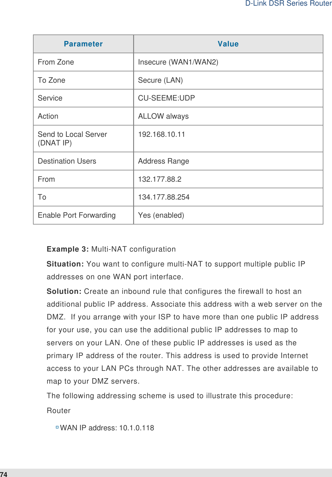
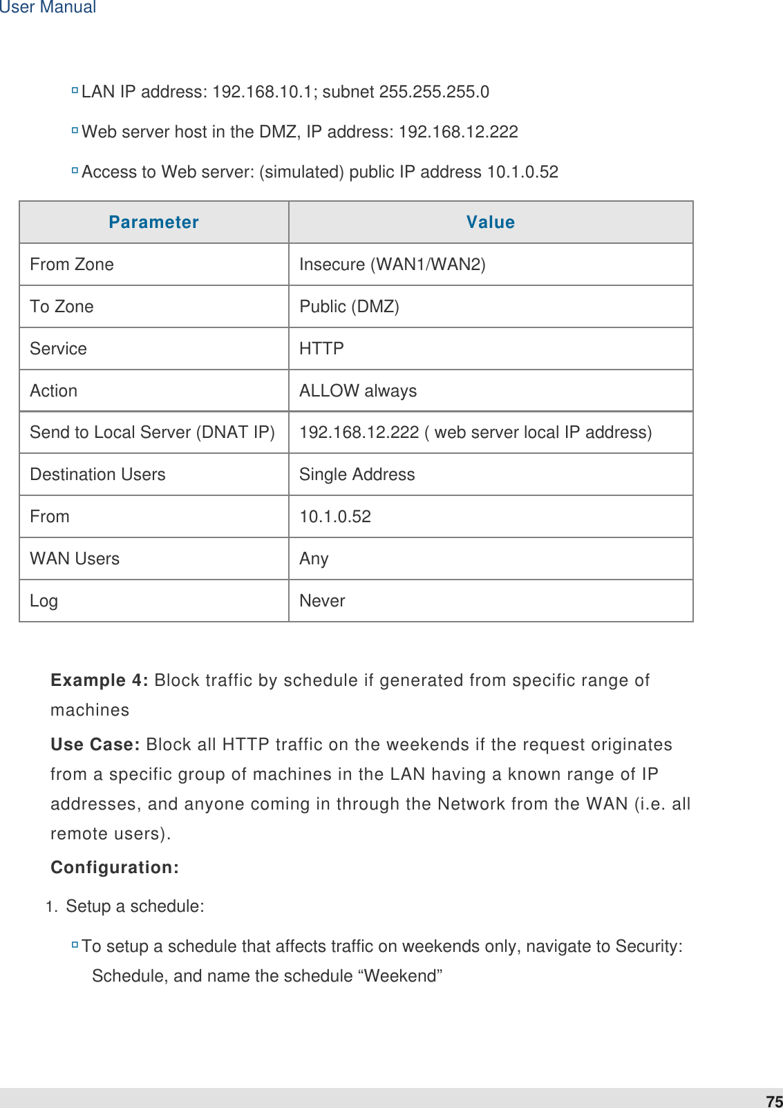
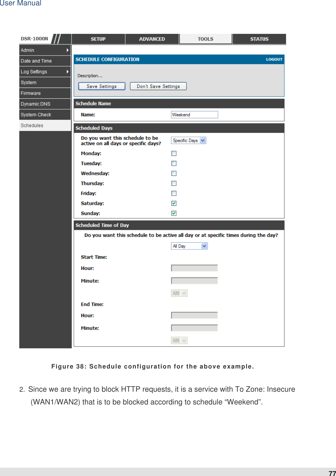
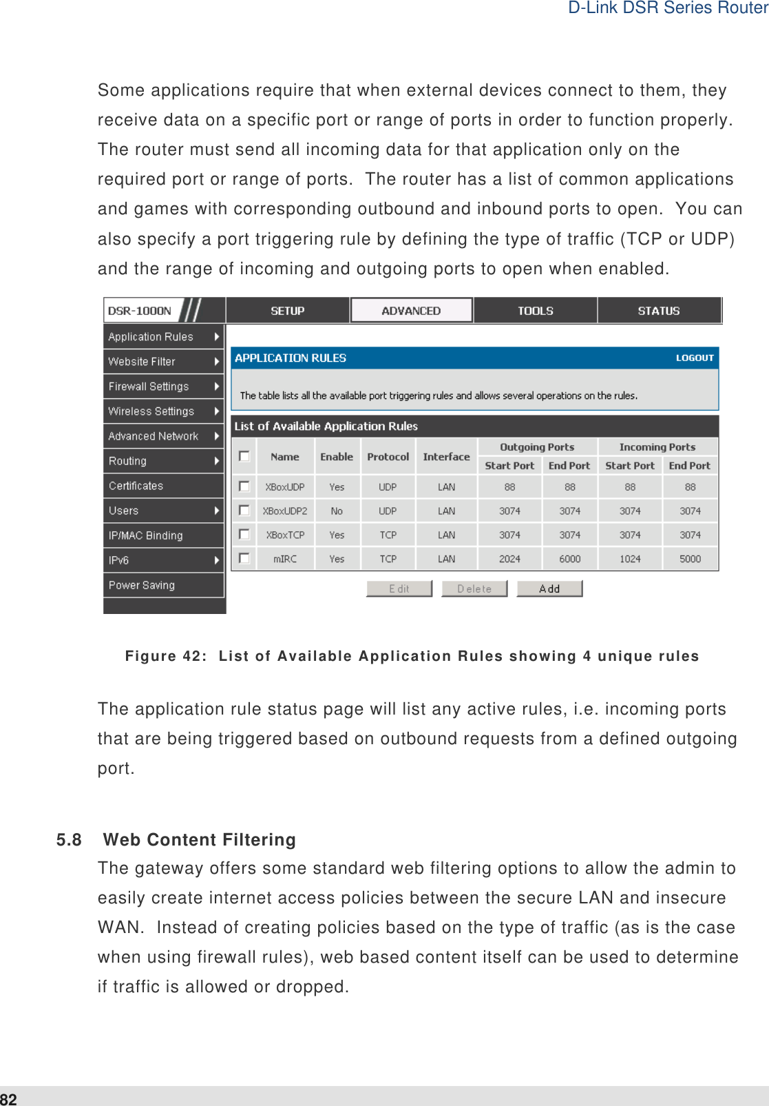
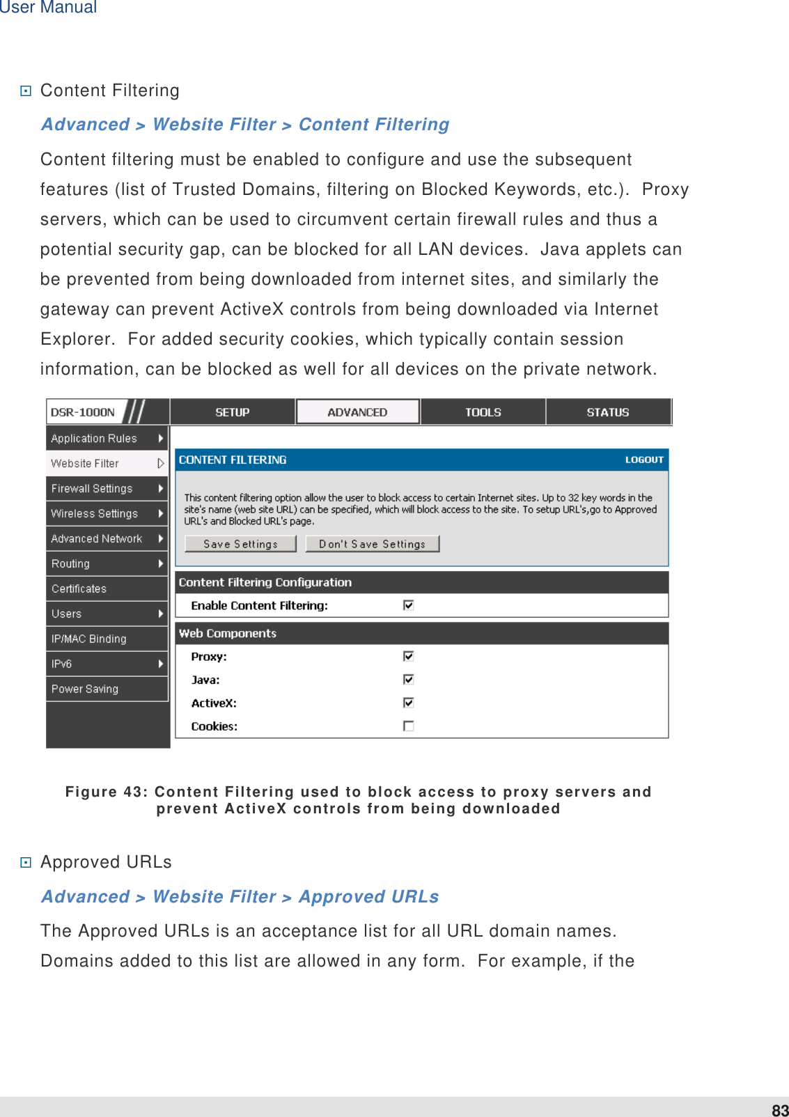
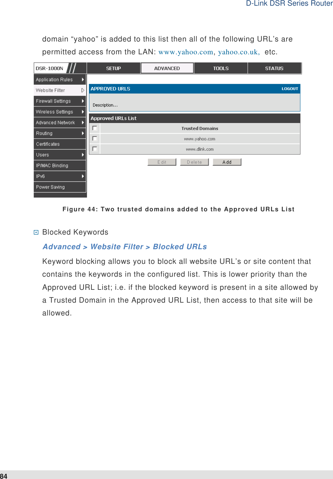
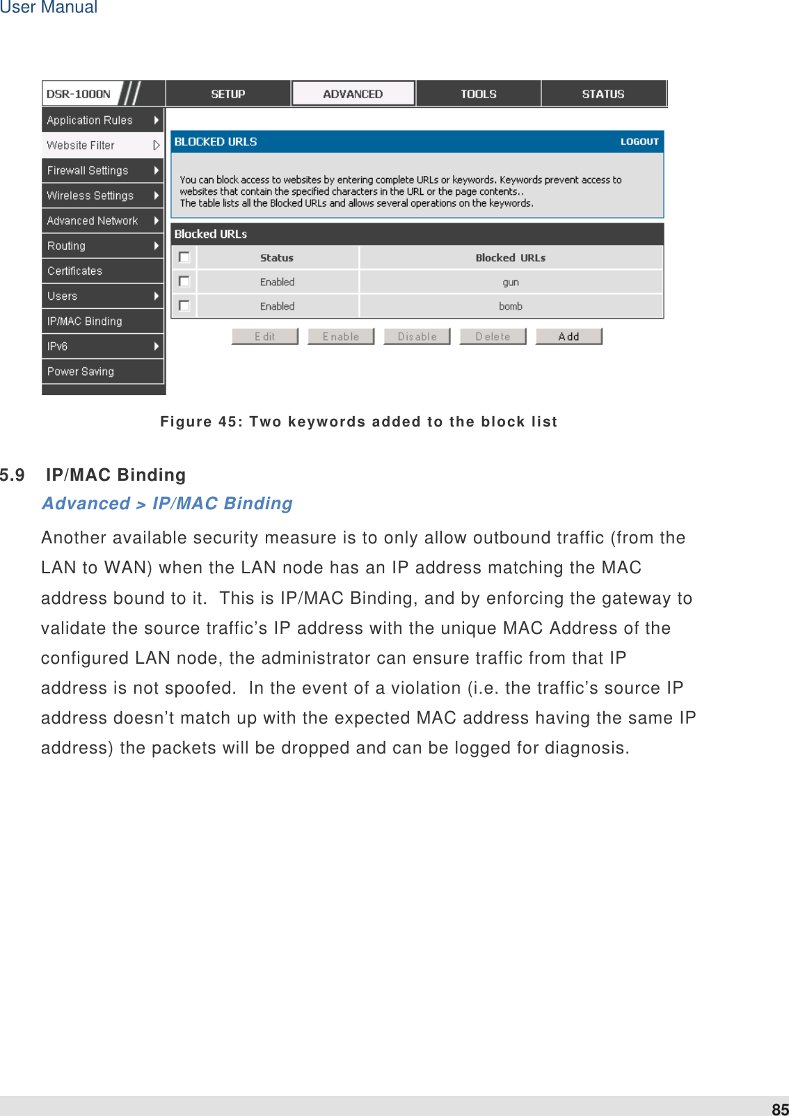
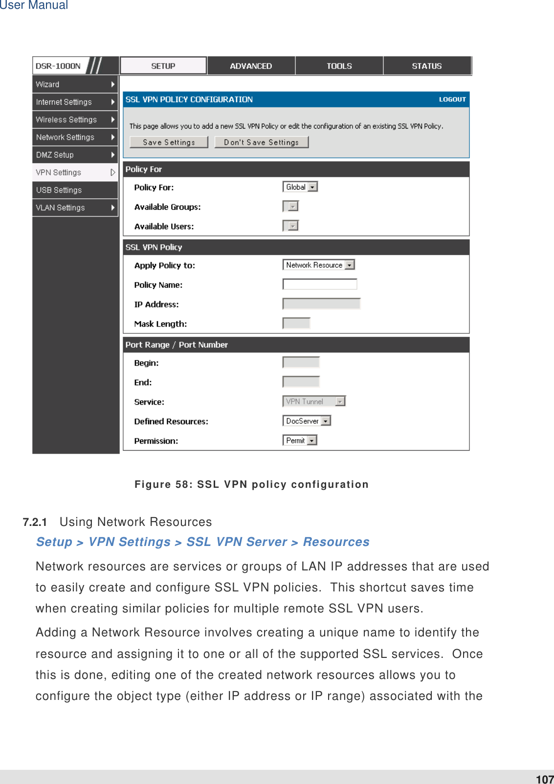
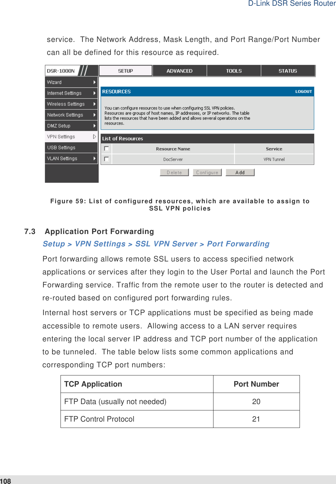
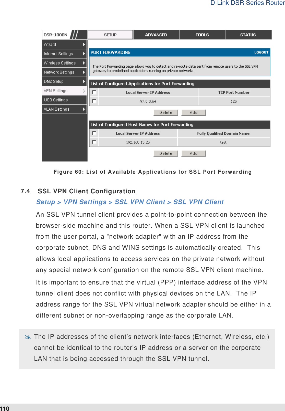
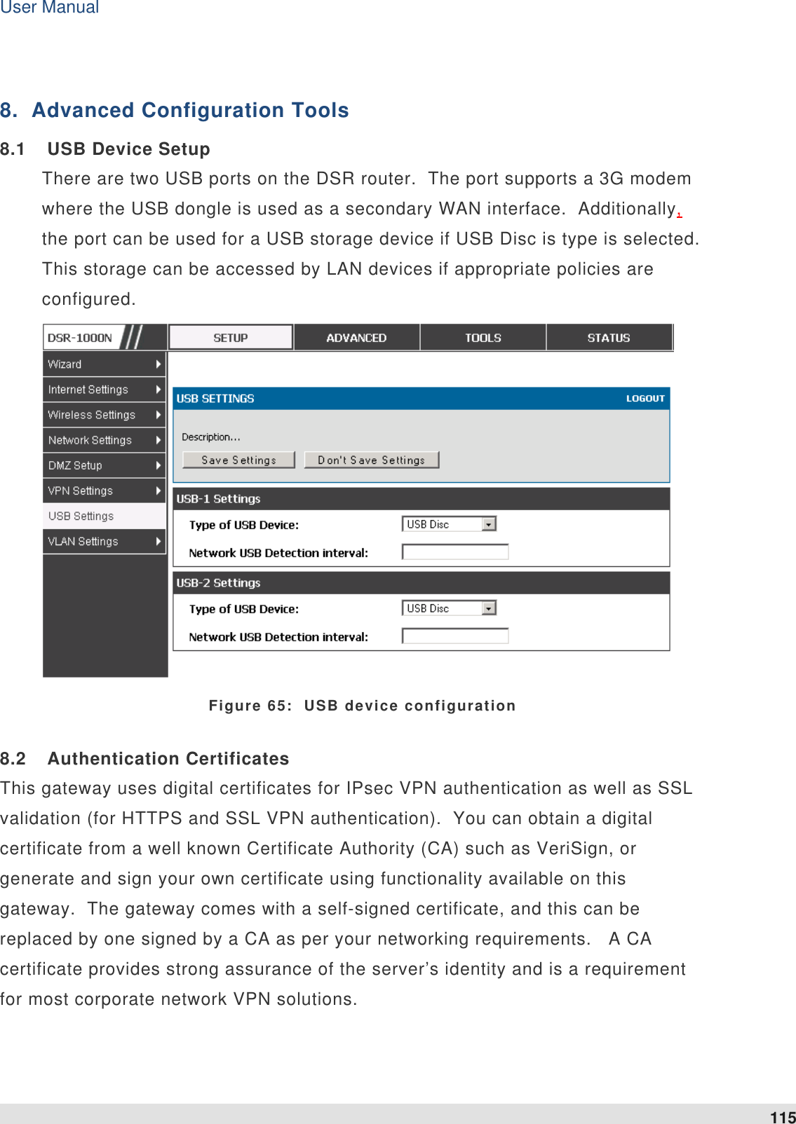
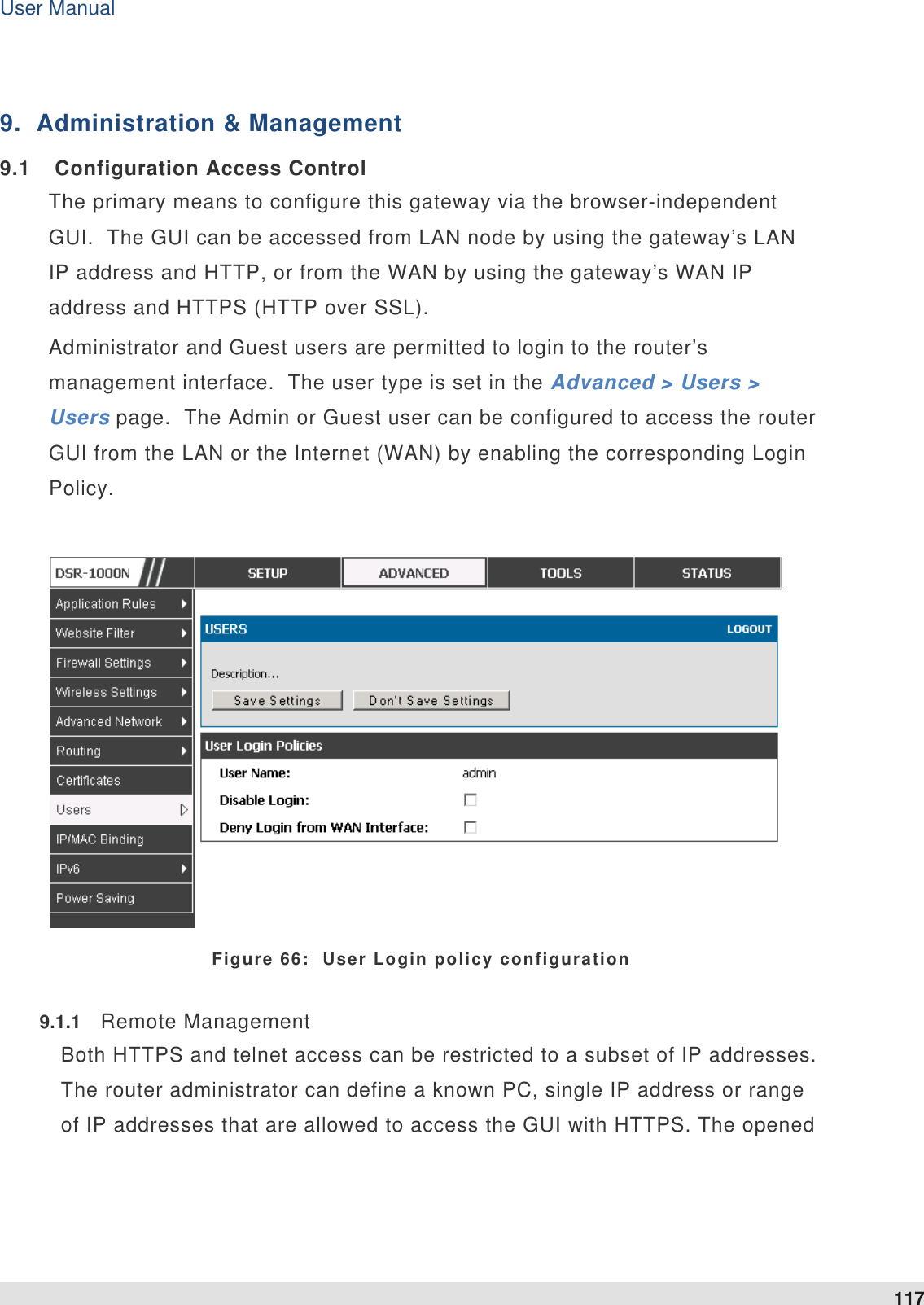
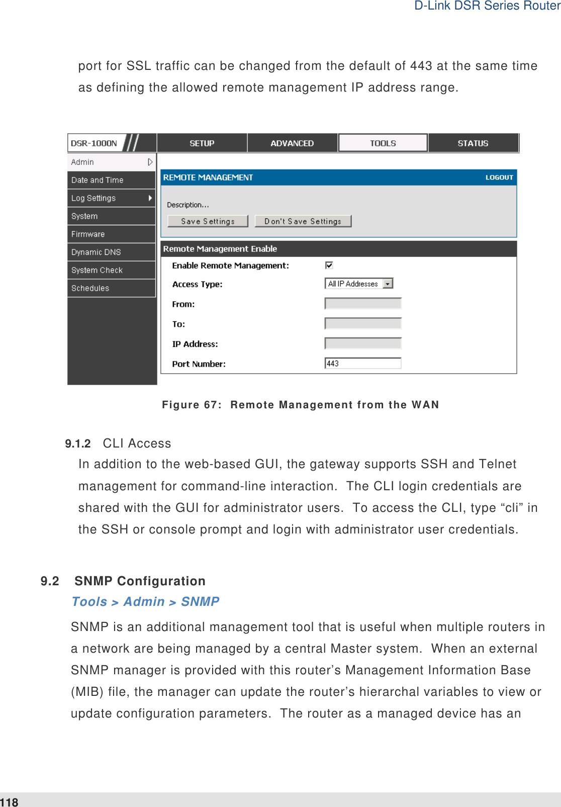
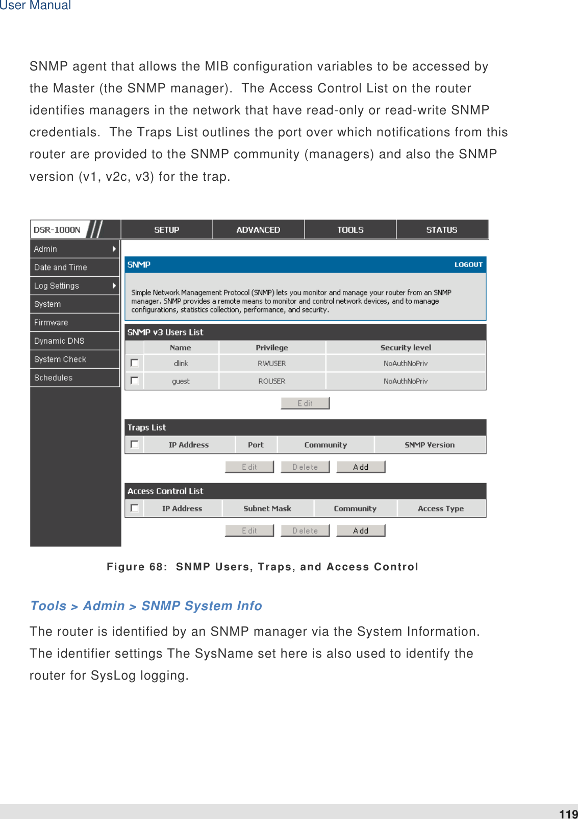
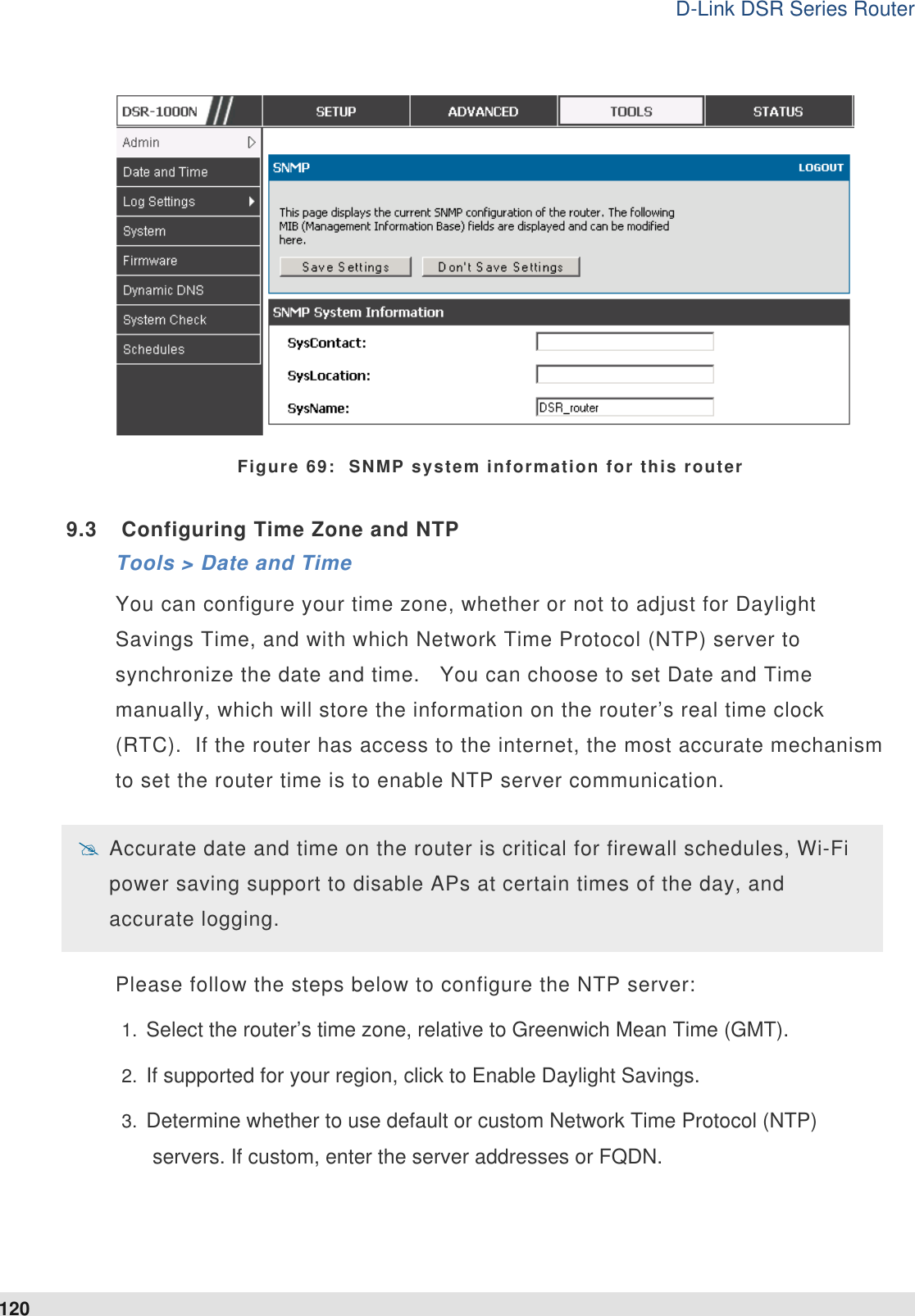
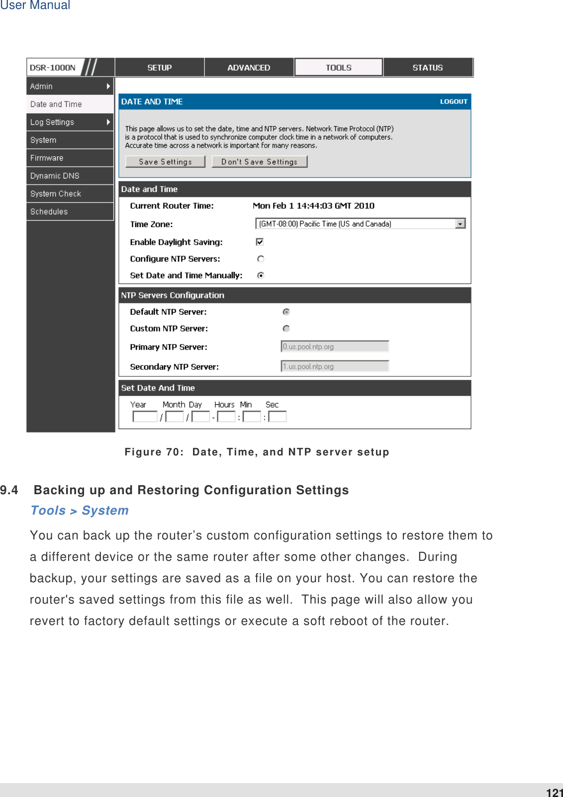
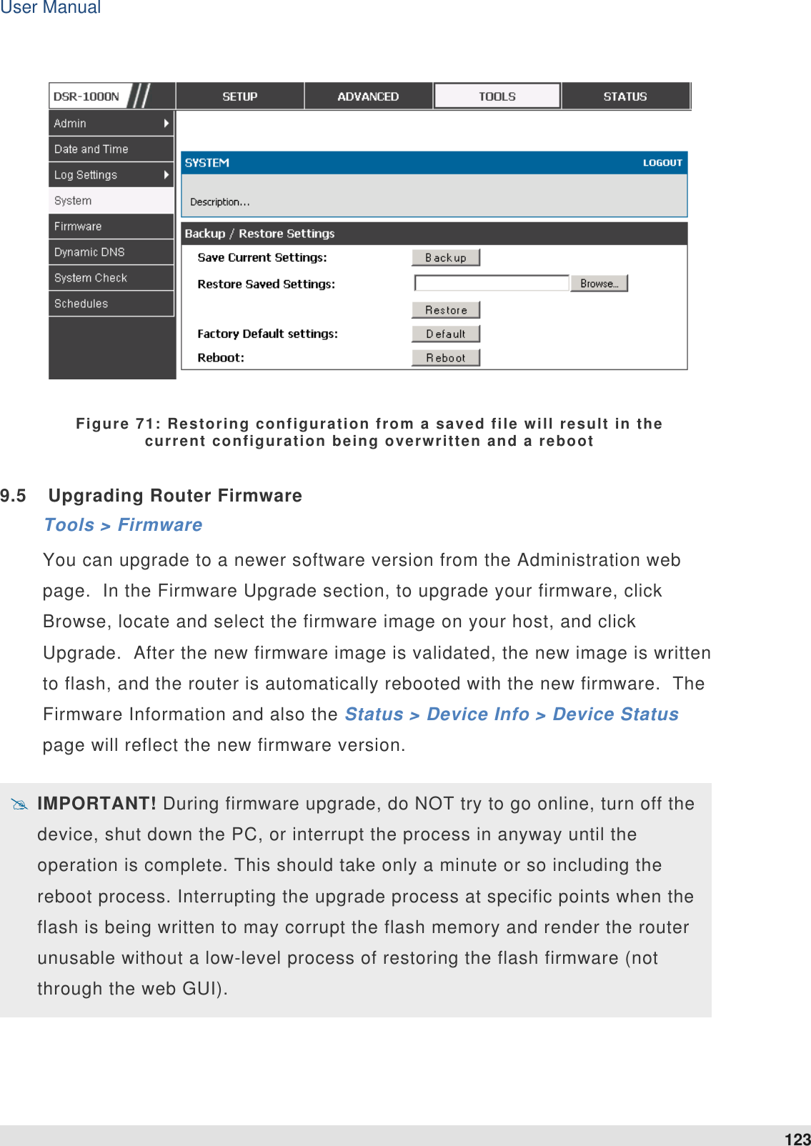
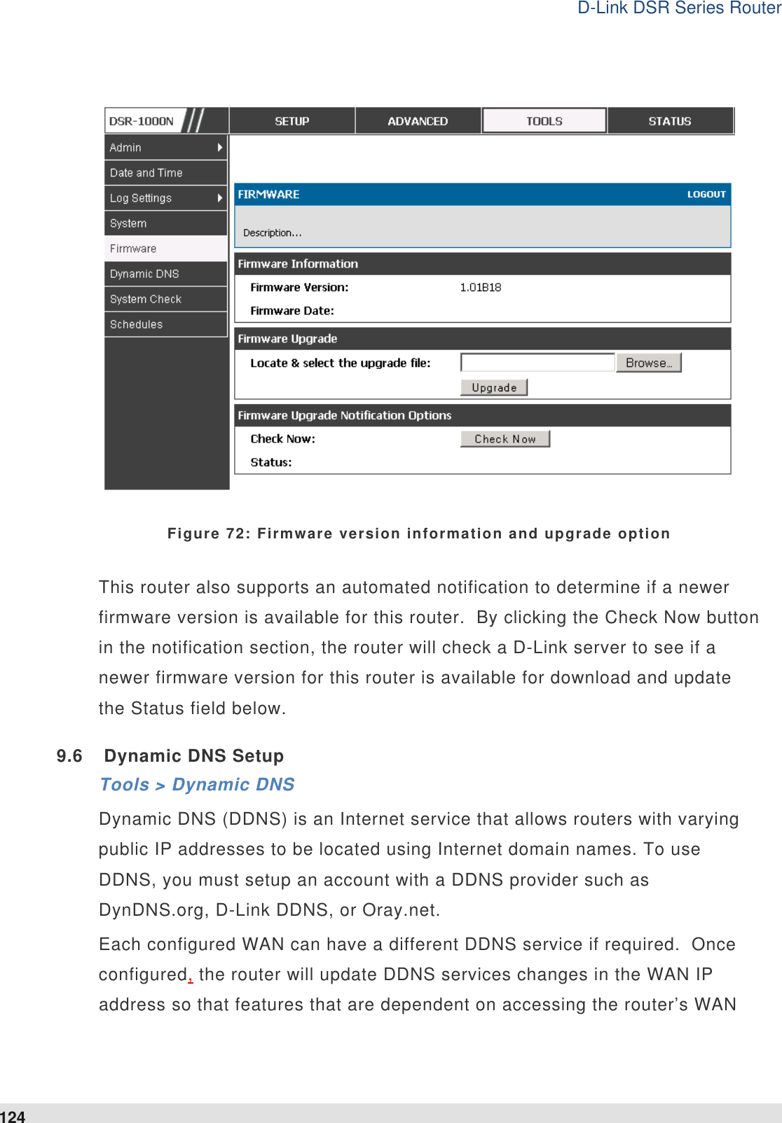
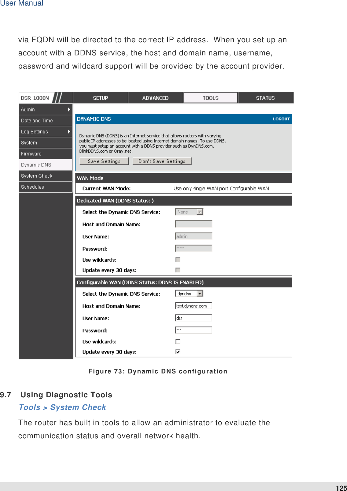
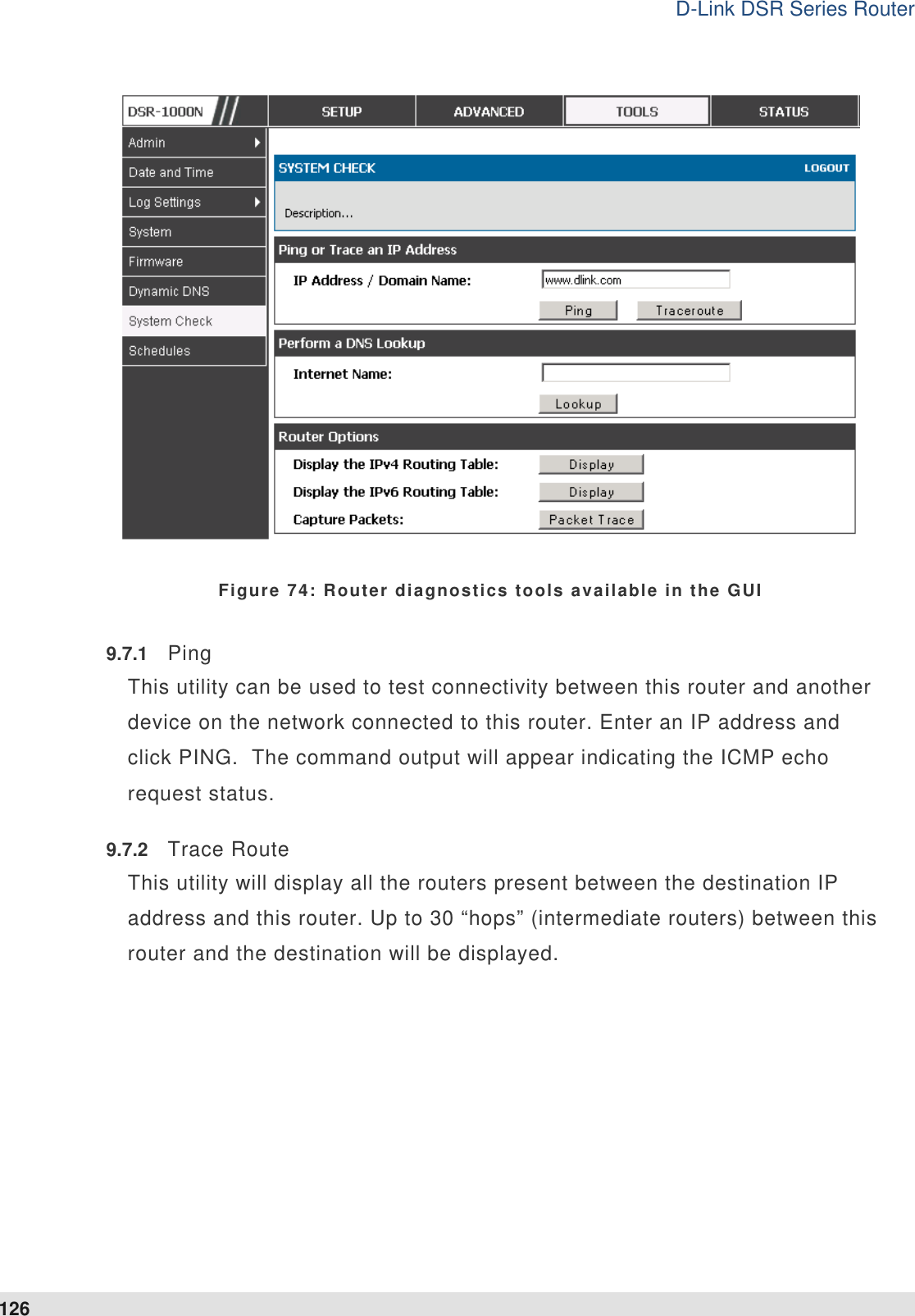
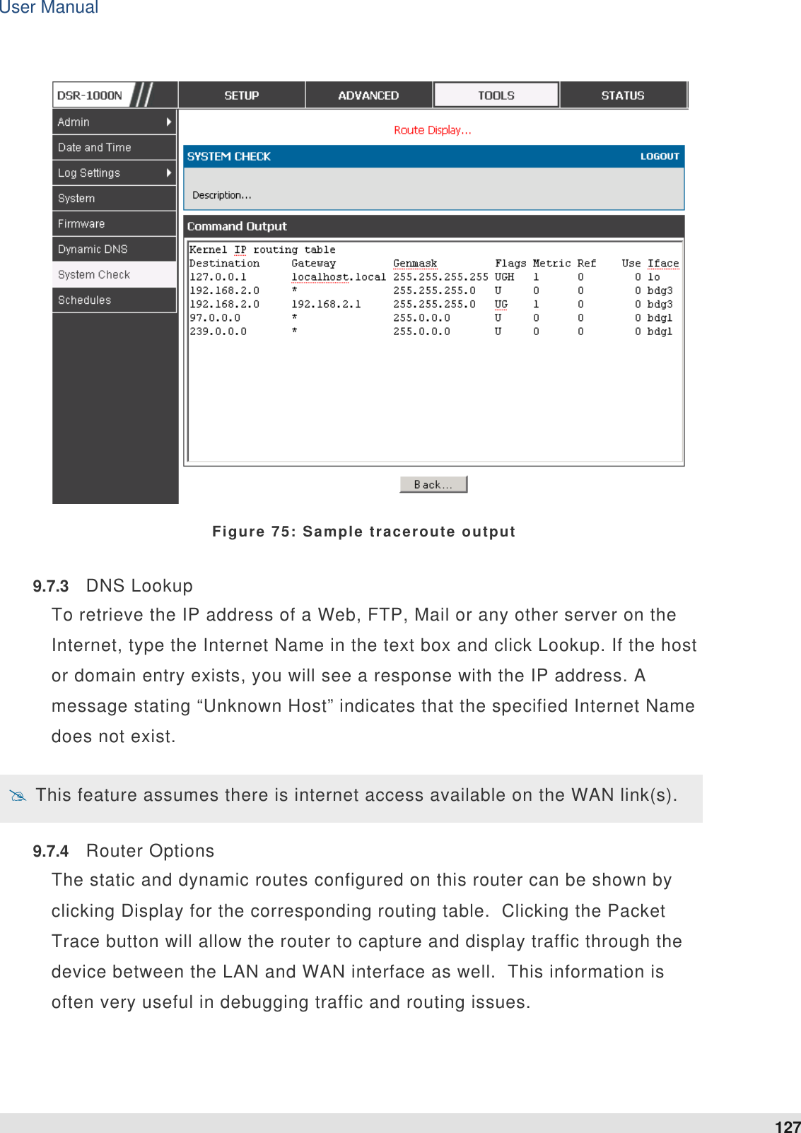
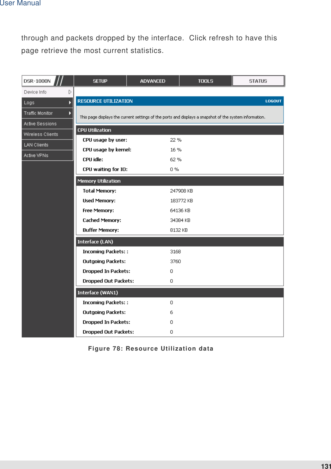
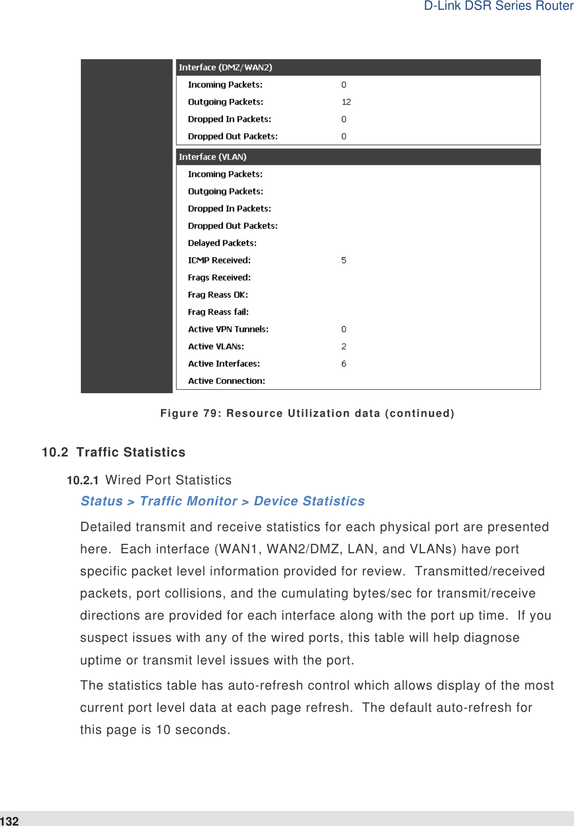
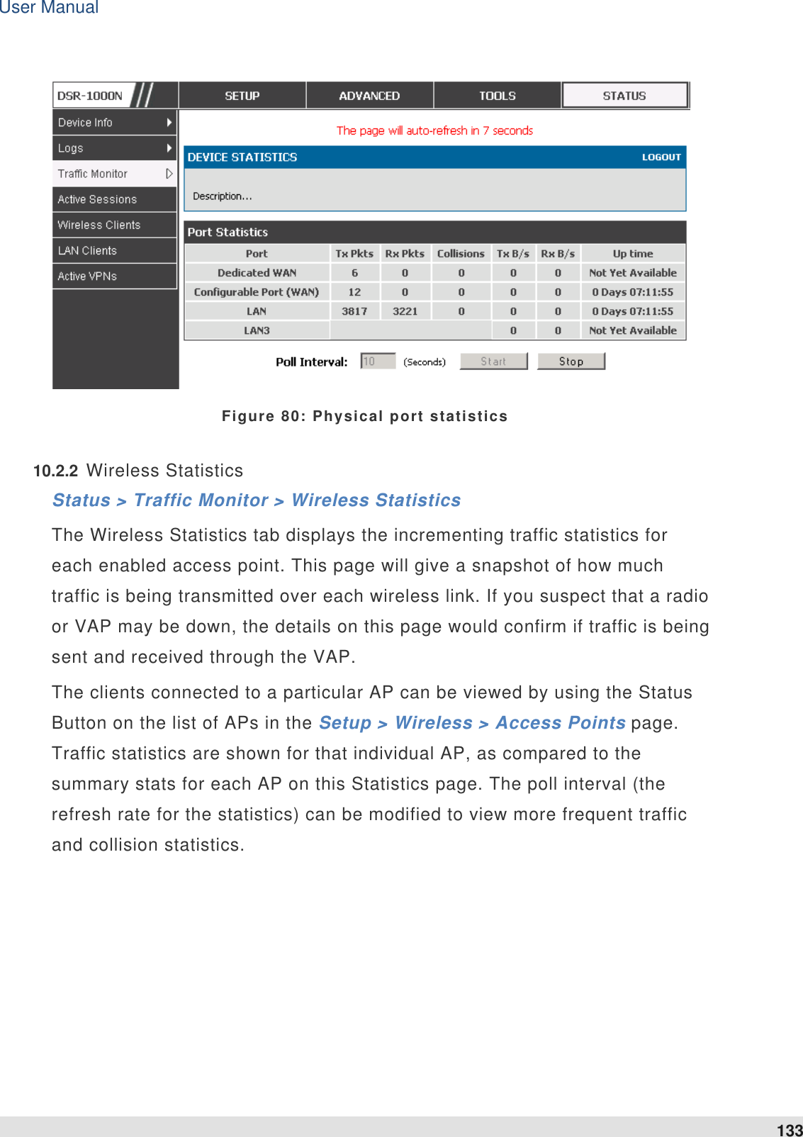
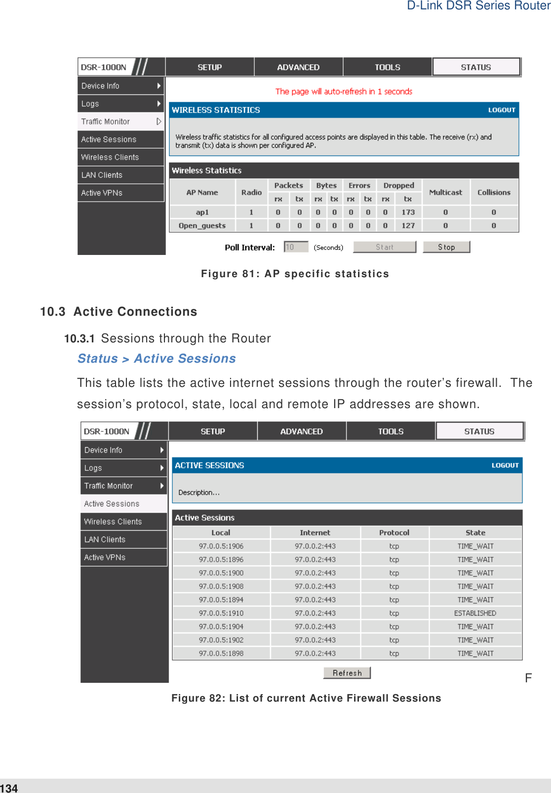
User Manual
Contents
1.
User Manual
2.
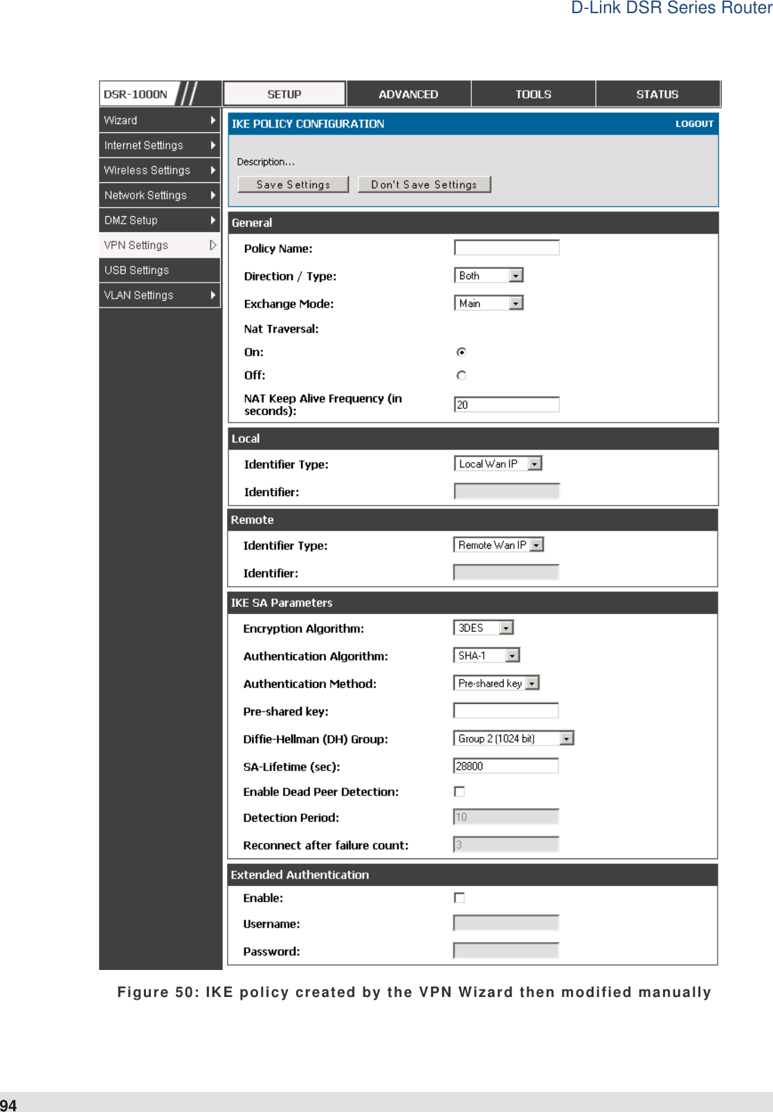
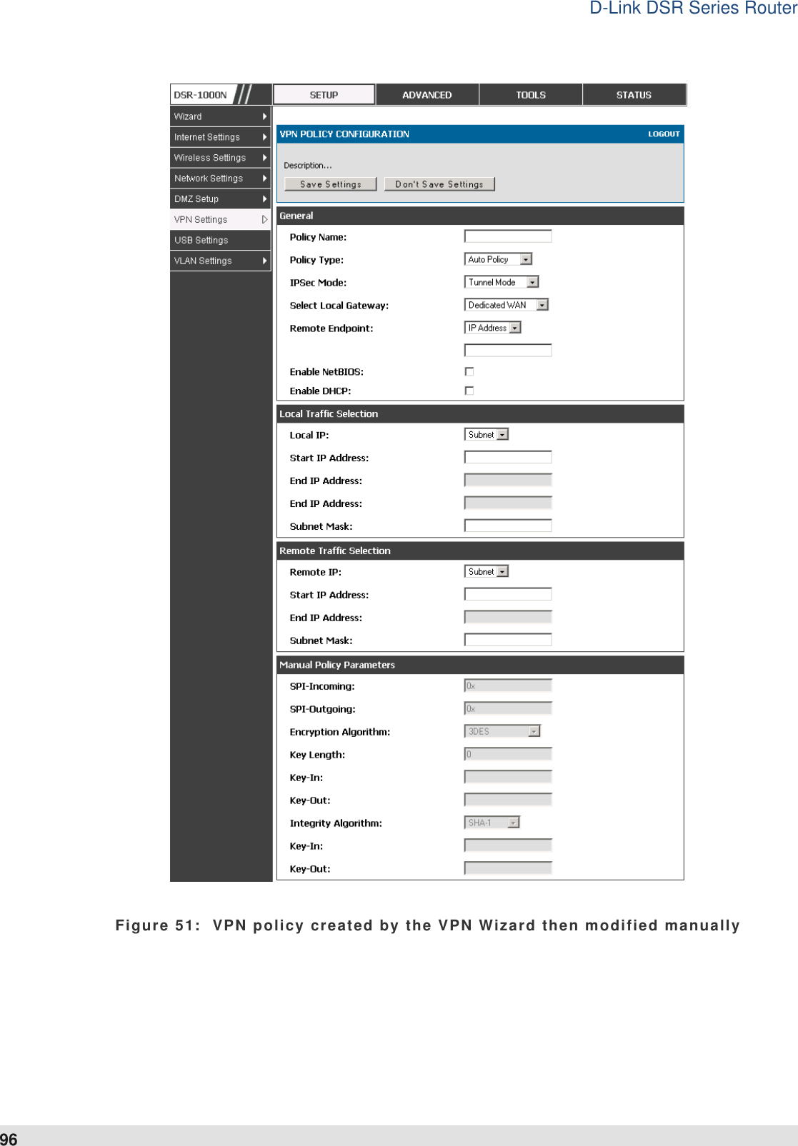
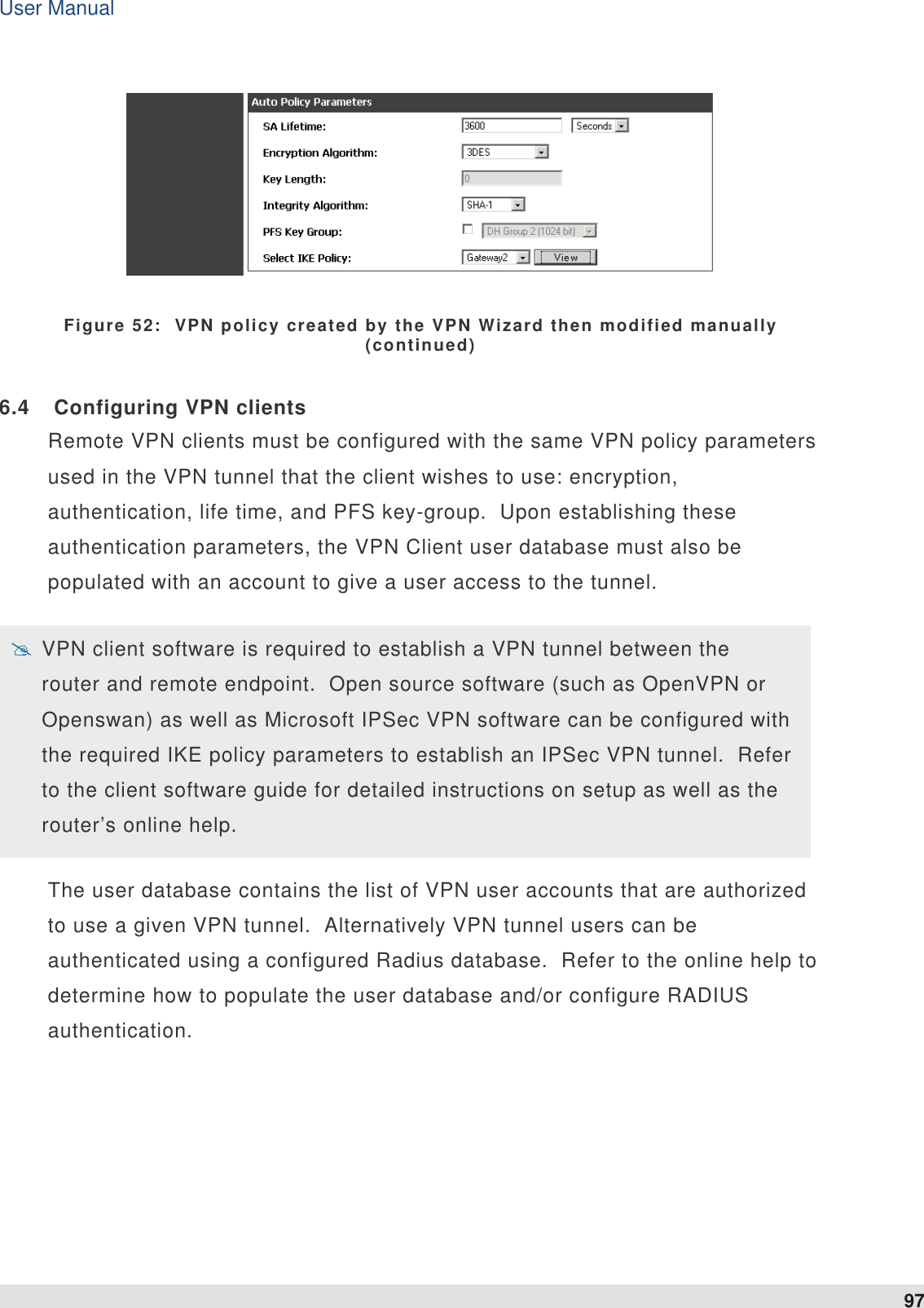
user manual
User Manual
Navigation menu
Upload a User Manual
Namespaces
Wiki Guide
HTML
PDF
Info
Views
User Manual
Discussion / Help
Navigation
![Česky [Czech] [D-Link Corporation] tímto prohlašuje, že tento [DSR-1000N] je ve shodě se základními požadavky a dalšími příslušnými ustanoveními směrnice 1999/5/ES. Dansk [Danish] Undertegnede [D-Link Corporation] erklæ rer herved, at følgende udstyr [DSR-1000N] overholder de væ sentlige krav og øvrige relevante krav i direktiv 1999/5/EF. Deutsch [German] Hiermit erklärt [D-Link Corporation], dass sich das Gerät [DSR-1000N] in Ü bereinstimmung mit den grundlegenden Anforderungen und den übrigen einschlägigen Bestimmungen der Richtlinie 1999/5/EG befindet. Eesti [Estonian] Käesolevaga kinnitab [D-Link Corporation] seadme [DSR-1000N] vastavust direktiivi 1999/5/EÜ põhinõuetele ja nimetatud direktiivist tulenevatele teistele asjakohastele sätetele. English Hereby, [D-Link Corporation], declares that this [DSR-1000N] is in compliance with the essential requirements and other relevant provisions of Directive 1999/5/EC. Español [Spanish] Por medio de la presente [D-Link Corporation] declara que el [DSR-1000N] cumple con los requisitos esenciales y cualesquiera otras disposiciones aplicables o exigibles de la Directiva 1999/5/CE. Ελληνική [Greek] ΜΕ ΣΗΝ ΠΑΡΟΤΑ [D-Link Corporation] ΔΗΛΩΝΕΙ ΟΣΙ [DSR-1000N] ΤΜΜΟΡΦΩΝΕΣΑΙ ΠΡΟ ΣΙ ΟΤΙΩΔΕΙ ΑΠΑΙΣΗΕΙ ΚΑΙ ΣΙ ΛΟΙΠΕ ΥΕΣΙΚΕ ΔΙΑΣΑΞΕΙ ΣΗ ΟΔΗΓΙΑ 1999/5/ΕΚ. Français [French] Par la présente [D-Link Corporation] déclare que l'appareil [DSR-1000N] est conforme aux exigences essentielles et aux autres dispositions pertinentes de la directive 1999/5/CE. Italiano [Italian] Con la presente [D-Link Corporation] dichiara che questo [DSR-1000N] è conforme ai requisiti essenziali ed alle altre disposizioni pertinenti stabilite dalla direttiva 1999/5/CE. Latviski [Latvian] Ar šo [D-Link Corporation] deklarē, ka [DSR-1000N] atbilst Direktīvas 1999/5/EK būtiskajām prasībām un citiem ar to saistītajiem noteikumiem. Lietuvių [Lithuanian] Šiuo [D-Link Corporation] deklaruoja, kad šis [DSR-1000N] atitinka esminius reikalavimus ir kitas 1999/5/EB Direktyvos nuostatas. Nederlands [Dutch] Hierbij verklaart [D-Link Corporation] dat het toestel [DSR-1000N] in overeenstemming is met de essentiële eisen en de andere relevante bepalingen van richtlijn 1999/5/EG. Malti [Maltese] Hawnhekk, [D-Link Corporation], jiddikjara li dan [DSR-1000N] jikkonforma mal-ħtiġijiet essenzjali u ma provvedimenti oħrajn relevanti li hemm fid-Dirrettiva 1999/5/EC. Magyar [Hungarian] Alulírott, [D-Link Corporation] nyilatkozom, hogy a [DSR-1000N] megfelel a vonatkozó alapvetõ követelményeknek és az 1999/5/EC irányelv egyéb elõírásainak. Polski [Polish] Niniejszym [D-Link Corporation] oświadcza, że [DSR-1000N] jest zgodny z zasadniczymi wymogami oraz pozostałymi stosownymi postanowieniami Dyrektywy 1999/5/EC.](https://usermanual.wiki/D-Link/SR1000NA1.User-Manual/User-Guide-1257301-Page-154.png)
![Português [Portuguese] [D-Link Corporation] declara que este [DSR-1000N]está conforme com os requisitos essenciais e outras disposições da Directiva 1999/5/CE. Slovensko [Slovenian] [D-Link Corporation] izjavlja, da je ta [DSR-1000N] v skladu z bistvenimi zahtevami in ostalimi relevantnimi določili direktive 1999/5/ES. Slovensky [Slovak] [D-Link Corporation] týmto vyhlasuje, že [DSR-1000N] spĺňa základné požiadavky a všetky príslušné ustanovenia Smernice 1999/5/ES. Suomi [Finnish] [D-Link Corporation] vakuuttaa täten että [DSR-1000N] tyyppinen laite on direktiivin 1999/5/EY oleellisten vaatimusten ja sitä koskevien direktiivin muiden ehtojen mukainen. Svenska [Swedish] Härmed intygar [D-Link Corporation] att denna [DSR-1000N] står I överensstämmelse med de väsentliga egenskapskrav och övriga relevanta bestämmelser som framgår av direktiv 1999/5/EG.](https://usermanual.wiki/D-Link/SR1000NA1.User-Manual/User-Guide-1257301-Page-155.png)