D Link SR1000NA1 SMB Wireless N Gigabit VPN Router User Manual TF1 DSR 1 0 0 UM 0002
D Link Corporation SMB Wireless N Gigabit VPN Router TF1 DSR 1 0 0 UM 0002
D Link >
Contents
- 1. User Manual
- 2. user manual
User Manual

1
D-Link DSR Series Router
User Manual
Copyright © 2010 TeamF1, Inc.
All rights reserved
Names mentioned are trademarks, registered trademarks or service marks of their respective
companies.
Part No.: TF1-DSR-1-0-0-UM-0002

D-Link DSR Series Router
2
TABLE OF CONTENTS
1.
INTRODUCTION -------------------------------------------------------------------------------------------------- 5
1.1
About this User Manual -------------------------------------------------------------------------------------- 5
1.2
Typographical Conventions --------------------------------------------------------------------------------- 5
2.
CONFIGURING YOUR NETWORK: LAN SETUP ---------------------------------------------------------- 7
2.1
LAN Configuration--------------------------------------------------------------------------------------------- 7
2.1.1
LAN Configuration in an IPv6 Network -------------------------------------------------------------- 10
2.1.2
Configuring IPv6 Router Advertisements ----------------------------------------------------------- 13
2.2
VLAN Configuration ----------------------------------------------------------------------------------------- 16
2.2.1
Associating VLANs to ports --------------------------------------------------------------------------- 18
2.3
Configurable Port: DMZ Setup --------------------------------------------------------------------------- 20
2.4
Universal Plug and Play (UPnP) ------------------------------------------------------------------------- 21
3.
CONNECTING TO THE INTERNET: WAN SETUP ------------------------------------------------------ 24
3.1
Internet Setup Wizard -------------------------------------------------------------------------------------- 24
3.2
WAN Configuration ----------------------------------------------------------------------------------------- 25
WAN Port IP address ---------------------------------------------------------------------------------------------- 26
WAN DNS Servers -------------------------------------------------------------------------------------------------- 26
DHCP WAN ---------------------------------------------------------------------------------------------------------- 27
3.2.1
PPPoE Profiles ------------------------------------------------------------------------------------------- 29
3.2.2
WAN Configuration in an IPv6 Network ------------------------------------------------------------- 30
3.2.3
Checking WAN Status ---------------------------------------------------------------------------------- 32
3.3
Bandwidth Controls ----------------------------------------------------------------------------------------- 34
3.4
Features with Multiple WAN Links ----------------------------------------------------------------------- 37
3.4.1
Auto Failover --------------------------------------------------------------------------------------------- 37
3.4.2
Load Balancing ------------------------------------------------------------------------------------------ 38
3.4.3
Protocol Bindings ---------------------------------------------------------------------------------------- 39
3.5
Routing Configuration -------------------------------------------------------------------------------------- 40
3.5.1
Routing Mode -------------------------------------------------------------------------------------------- 40
3.5.2
Dynamic Routing (RIP) --------------------------------------------------------------------------------- 42
3.5.3
Static Routing -------------------------------------------------------------------------------------------- 44
3.6
Configurable Port - WAN Option ------------------------------------------------------------------------- 45
3.7
WAN Port Settings ------------------------------------------------------------------------------------------ 47
4.
WIRELESS ACCESS POINT SETUP ----------------------------------------------------------------------- 50
4.1
Wireless Settings Wizard ---------------------------------------------------------------------------------- 50
4.1.1
Wireless Network Setup Wizard ---------------------------------------------------------------------- 51
4.1.2
Add Wireless Device with WPS ----------------------------------------------------------------------- 52
4.1.3
Manual Wireless Network Setup --------------------------------------------------------------------- 52
4.2
Wireless Profiles -------------------------------------------------------------------------------------------- 52
4.2.1
WEP Security --------------------------------------------------------------------------------------------- 54
4.2.2
WPA or WPA2 with PSK ------------------------------------------------------------------------------- 55
4.2.3
RADIUS Authentication -------------------------------------------------------------------------------- 56
4.3
Creating and Using Access Points ---------------------------------------------------------------------- 57
4.3.1
Primary benefits of Virtual APs: ---------------------------------------------------------------------- 59
4.4
Tuning Radio Specific Settings --------------------------------------------------------------------------- 60
4.5
Advanced Wireless Settings ------------------------------------------------------------------------------ 61
4.6
Wi-Fi Protected Setup (WPS) ----------------------------------------------------------------------------- 62
5.
SECURING THE PRIVATE NETWORK -------------------------------------------------------------------- 65

User Manual
3
5.1
Firewall Rules ------------------------------------------------------------------------------------------------ 65
5.2
Defining Rule Schedules ---------------------------------------------------------------------------------- 67
5.3
Configuring Firewall Rules -------------------------------------------------------------------------------- 68
5.3.1
Firewall Rule Configuration Examples -------------------------------------------------------------- 73
5.4
Security on Custom Services ----------------------------------------------------------------------------- 78
5.5
ALG support -------------------------------------------------------------------------------------------------- 79
5.6
VPN Passthrough for Firewall ---------------------------------------------------------------------------- 80
5.7
Application Rules -------------------------------------------------------------------------------------------- 81
5.8
Web Content Filtering -------------------------------------------------------------------------------------- 82
5.9
IP/MAC Binding ---------------------------------------------------------------------------------------------- 85
5.10
Intrusion Prevention (IPS) --------------------------------------------------------------------------------- 86
5.10.1
Protecting from Internet Attacks ---------------------------------------------------------------------- 87
6.
IPSEC VPN ------------------------------------------------------------------------------------------------------- 89
6.1
VPN Wizard --------------------------------------------------------------------------------------------------- 89
6.2
Configuring IKE Policies ----------------------------------------------------------------------------------- 92
6.2.1
Configuring an IKE Policy using XAUTH ----------------------------------------------------------- 95
6.3
Configuring VPN Policies ---------------------------------------------------------------------------------- 95
6.4
Configuring VPN clients ----------------------------------------------------------------------------------- 97
6.5
PPTP / L2TP Tunnels -------------------------------------------------------------------------------------- 98
6.5.1
PPTP Tunnel Support ---------------------------------------------------------------------------------- 98
6.5.2
L2TP Tunnel Support ----------------------------------------------------------------------------------- 98
7.
SSL VPN -------------------------------------------------------------------------------------------------------- 101
7.1
Users, Groups, and Domains --------------------------------------------------------------------------- 102
7.1.1
User Types and Passwords ------------------------------------------------------------------------- 103
7.2
Using SSL VPN Policies --------------------------------------------------------------------------------- 104
7.2.1
Using Network Resources --------------------------------------------------------------------------- 107
7.3
Application Port Forwarding ---------------------------------------------------------------------------- 108
7.4
SSL VPN Client Configuration -------------------------------------------------------------------------- 110
7.5
User Portal -------------------------------------------------------------------------------------------------- 112
7.5.1
Creating Portal Layouts ------------------------------------------------------------------------------ 113
8.
ADVANCED CONFIGURATION TOOLS ----------------------------------------------------------------- 115
8.1
USB Device Setup ---------------------------------------------------------------------------------------- 115
8.2
Authentication Certificates ------------------------------------------------------------------------------ 115
9.
ADMINISTRATION & MANAGEMENT ------------------------------------------------------------------- 117
9.1
Configuration Access Control --------------------------------------------------------------------------- 117
9.1.1
Remote Management --------------------------------------------------------------------------------- 117
9.1.2
CLI Access ---------------------------------------------------------------------------------------------- 118
9.2
SNMP Configuration -------------------------------------------------------------------------------------- 118
9.3
Configuring Time Zone and NTP ----------------------------------------------------------------------- 120
9.4
Backing up and Restoring Configuration Settings -------------------------------------------------- 121
9.5
Upgrading Router Firmware ----------------------------------------------------------------------------- 123
9.6
Dynamic DNS Setup -------------------------------------------------------------------------------------- 124
9.7
Using Diagnostic Tools ---------------------------------------------------------------------------------- 125
9.7.1
Ping ------------------------------------------------------------------------------------------------------- 126
9.7.2
Trace Route -------------------------------------------------------------------------------------------- 126

D-Link DSR Series Router
4
9.7.3
DNS Lookup -------------------------------------------------------------------------------------------- 127
9.7.4
Router Options ----------------------------------------------------------------------------------------- 127
10.
ROUTER STATUS AND STATISTICS ---------------------------------------------------------------- 128
10.1
System Overview ------------------------------------------------------------------------------------------ 128
10.1.1
Device Status ------------------------------------------------------------------------------------------ 128
10.1.2
Resource Utilization ---------------------------------------------------------------------------------- 130
10.2
Traffic Statistics ------------------------------------------------------------------------------------------- 132
10.2.1
Wired Port Statistics ---------------------------------------------------------------------------------- 132
10.2.2
Wireless Statistics ------------------------------------------------------------------------------------- 133
10.3
Active Connections --------------------------------------------------------------------------------------- 134
10.3.1
Sessions through the Router ------------------------------------------------------------------------ 134
10.3.2
Wireless Clients ---------------------------------------------------------------------------------------- 135
10.3.3
LAN Clients --------------------------------------------------------------------------------------------- 135
10.3.4
Active VPN Tunnels ----------------------------------------------------------------------------------- 136
11.
TROUBLE SHOOTING ---------------------------------------------------------------------------------- 138
11.1
Internet connection --------------------------------------------------------------------------------------- 138
11.2
Date and time ---------------------------------------------------------------------------------------------- 140
11.3
Pinging to Test LAN Connectivity ---------------------------------------------------------------------- 141
11.3.1
Testing the LAN path from your PC to your router --------------------------------------------- 141
11.3.2
Testing the LAN path from your PC to a remote device --------------------------------------- 142
11.4
Restoring factory-default configuration settings ---------------------------------------------------- 143
12.
CREDITS --------------------------------------------------------------------------------------------------- 145
APPENDIX A.
GLOSSARY ----------------------------------------------------------------------------------- 146
APPENDIX B.
FACTORY DEFAULT SETTINGS -------------------------------------------------------- 149
APPENDIX C.
STANDARD SERVICES AVAILABLE FOR PORT FORWARDING & FIREWALL
CONFIGURATION ------------------------------------------------------------------------------------------------ 151

User Manual
5
1. Introduction
The D-Link DSR series of routers are enterprise grade security gateway solutions
with Firewall, VPN and in some cases 802.11n Access Point capabilities. These
devices have wizards to allow for quick and easy configuration for internet access,
VPN tunnels, and wireless networks. The GUI provides all the capabilities for
novice and advanced users to administer this secure and feature rich router.
1.1 About this User Manual
This document is a high level manual to allow new D-Link DSR Series Router
users to configure connectivity, setup VPN tunnels, establish firewall rules
and perform general administrative tasks. Typical deployment and use case
scenarios are described in each section. For more detailed setup instructions
and explanations of each configuration parameter, refer to the online help that
can be accessed from each page in the router GUI.
1.2 Typographical Conventions
The following is a list of the various terms, followed by an example of how that
term is represented in this document:
Product Name – D-Link DSR-1000 / DSR-1000N / DSR-500 / DSR-500N
GUI Menu Path/GUI Navigation – Monitoring > Router Status
User input – Text
Important note –

7
2. Configuring Your Network: LAN Setup
It is assumed that the user has a machine for management connected to the LAN
to the router. The LAN connection may be through the wired Ethernet ports
available on the router, or once the initial setup is complete, the device may also
be managed through its wireless interface as it is bridged with the LAN. Access
the router’s graphical user interface (GUI) for management by using any web
browser, such as Microsoft Internet Explorer or Mozilla Firefox:
Go to http://192.168.10.1 (default IP address) to display the router’s
management login screen.
Default login credentials for the management GUI:
Username: admin
Password: admin
If the router’s LAN IP address was changed, use that IP address in the
navigation bar of the browser to access the router’s management UI.
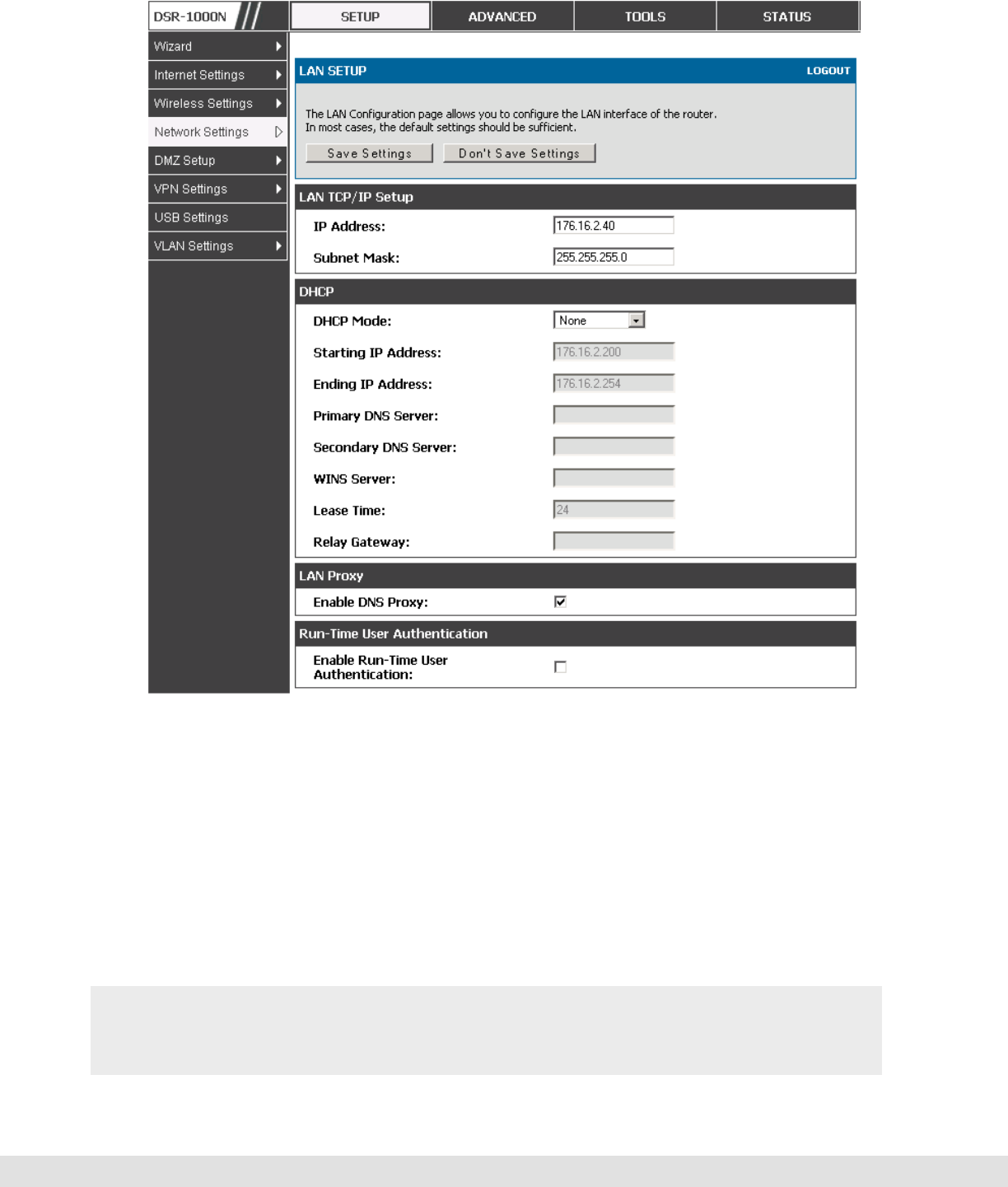
2.1 LAN Configuration
Setup > Network Settings > LAN Configuration
By default, the router functions as a Dynamic Host Configuration Protocol
(DHCP) server to the hosts on the WLAN or LAN network. With DHCP, PCs
and other LAN devices can be assigned IP addresses as well as addresses
for DNS servers, Windows Internet Name Service (WINS) servers, and the
default gateway. With the DHCP server enabled the router’s IP address
serves as the gateway address for LAN and WLAN clients. The PCs in the
LAN are assigned IP addresses from a pool of addresses specified in this
procedure. Each pool address is tested before it is assigned to avoid
duplicate addresses on the LAN.
For most applications the default DHCP and TCP/IP settings are satisfactory.
If you want another PC on your network to be the DHCP server or if you are
manually configuring the network settings of all of your PCs, set the DHCP

D-Link DSR Series Router
8
mode to ‘none’. DHCP relay can be used to forward DHCP lease information
from another LAN device that is the network’s DHCP server; this is
particularly useful for wireless clients.
Instead of using a DNS server, you can use a Windows Internet Naming
Service (WINS) server. A WINS server is the equivalent of a DNS server but
uses the NetBIOS protocol to resolve hostnames. The router includes the
WINS server IP address in the DHCP configuration when acknowledging a
DHCP request from a DHCP client.
You can also enable DNS proxy for the LAN. When this is enabled the router
then as a proxy for all DNS requests and communicates with the ISP’s DNS
servers. When disabled all DHCP clients receive the DNS IP addresses of the
ISP.
To configure LAN Connectivity, please follow the steps below:
1. In the LAN Setup page, enter the following information for your router:
IP address (factory default: 192.168.10.1).
If you change the IP address and click Save Settings, the GUI will not
respond. Open a new connection to the new IP address and log in again. Be
sure the LAN host (the machine used to manage the router) has obtained IP
address from newly assigned pool (or has a static IP address in the router’s
LAN subnet) before accessing the router via changed IP address.
Subnet mask (factory default: 255.255.255.0).
2. In the DHCP section, select the DHCP mode:
None: the router’s DHCP server is disabled for the LAN
DHCP Server. With this option the router assigns an IP address within the
specified range plus additional specified information to any LAN device that
requests DHCP served addresses.

User Manual
9
DHCP Relay: With this option enabled, DHCP clients on the LAN can receive IP
address leases and corresponding information from a DHCP server on a
different subnet. Specify the Relay Gateway, and when LAN clients make a
DHCP request it will be passed along to the server accessible via the Relay
Gateway IP address.
If DHCP is being enabled, enter the following DHCP server parameters:
• Starting and Ending IP Addresses: Enter the first and last continuous
addresses in the IP address pool. Any new DHCP client joining the LAN is
assigned an IP address in this range. The default starting address is
192.168.10.2. The default ending address is 192.168.10.100. These
addresses should be in the same IP address subnet as the router’s LAN
IP address. You may wish to save part of the subnet range for devices
with statically assigned IP addresses in the LAN.
• Primary and Secondary DNS servers: If configured domain name system
(DNS) servers are available on the LAN enter their IP addresses here.
• WINS Server (optional): Enter the IP address for the WINS server or, if
present in your network, the Windows NetBios server.
• Lease Time: Enter the time, in hours, for which IP addresses are leased to
clients.
Enable DNS Proxy: To enable the router to act as a proxy for all DNS requests
and communicate with the ISP’s DNS servers, click the checkbox.
3. Click Save Settings to apply all changes.
D-Link DSR Series Router
10
Figure 1: Setup page for LAN TCP/IP settings
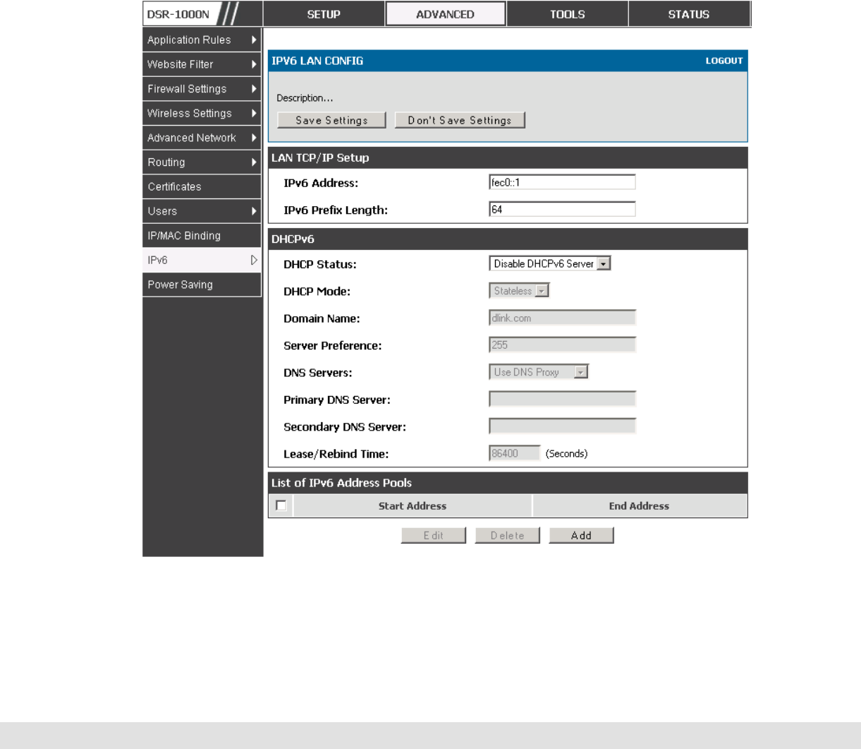
2.1.1 LAN Configuration in an IPv6 Network
Advanced > IPv6 > IPv6 LAN > IPv6 LAN Config
In IPv6 mode, the LAN DHCP server is enabled by default (similar to IPv4
mode). The DHCPv6 server will serve IPv6 addresses from configured
address pools with the IPv6 Prefix Length assigned to the LAN.
IPv4 / IPv6 mode must be enabled in the Advanced > IPv6 > IP mode to
enable IPv6 configuration options.
User Manual
11
2.1.1.1 LAN Settings
The default IPv6 LAN address for the router is fec0::1. You can change this
128 bit IPv6 address based on your network requirements. The other field
that defines the LAN settings for the router is the prefix length. The IPv6
network (subnet) is identified by the initial bits of the address called the
prefix. By default this is 64 bits long. All hosts in the network have common
initial bits for their IPv6 address; the number of common initial bits in the
network’s addresses is set by the prefix length field.
Figure 2: IPv6 LAN and DHCPv6 configuration

D-Link DSR Series Router
12
If you change the IP address and click Save Settings, the GUI will not
respond. Open a new connection to the new IP address and log in again. Be
sure the LAN host (the machine used to manage the router) has obtained IP
address from newly assigned pool (or has a static IP address in the router’s
LAN subnet) before accessing the router via changed IP address.
As with an IPv4 LAN network, the router has a DHCPv6 server. If enabled,
the router assigns an IP address within the specified range plus additional
specified information to any LAN PC that requests DHCP served addresses.
The following settings are used to configure the DHCPv6 server:
DHCP Mode: The IPv6 DHCP server is either stateless or stateful. If stateless
is selected an external IPv6 DHCP server is not required as the IPv6 LAN
hosts are auto-configured by this router. In this case the router advertisement
daemon (RADVD) must be configured on this device and ICMPv6 router
discovery messages are used by the host for auto-configuration. There are no
managed addresses to serve the LAN nodes. If stateful is selected the IPv6
LAN host will rely on an external DHCPv6 server to provide required
configuration settings
The domain name of the DHCPv6 server is an optional setting
Server Preference is used to indicate the preference level of this DHCP server.
DHCP advertise messages with the highest server preference value to a LAN
host are preferred over other DHCP server advertise messages. The default
is 255.
The DNS server details can be manually entered here (primary/secondary
options. An alternative is to allow the LAN DHCP client to receive the DNS
server details from the ISP directly. By selecting Use DNS proxy, this router
acts as a proxy for all DNS requests and communicate with the ISP’s DNS
servers (a WAN configuration parameter).

User Manual
13
Primary and Secondary DNS servers: If there are configured domain name
system (DNS) servers available on the LAN enter the IP addresses here.
Lease/Rebind time sets the duration of the DHCPv6 lease from this router to
the LAN client.
2.1.1.2 IPv6 Address Pools
This feature allows you to define the IPv6 delegation prefix for a range of IP
addresses to be served by the gateway’s DHCPv6 server. Using a
delegation prefix you can automate the process of informing other
networking equipment on the LAN of DHCP information specific for the
assigned prefix.
2.1.2 Configuring IPv6 Router Advertisements
Router Advertisements are analogous to IPv4 DHCP assignments for LAN
clients, in that the router will assign an IP address and supporting network
information to devices that are configured to accept such details. Router
Advertisement is required in an IPv6 network is required for stateless auto
configuration of the IPv6 LAN. By configuring the Router Advertisement
Daemon on this router, the device will listen on the LAN for router
solicitations and respond to these LAN hosts with router advisements.
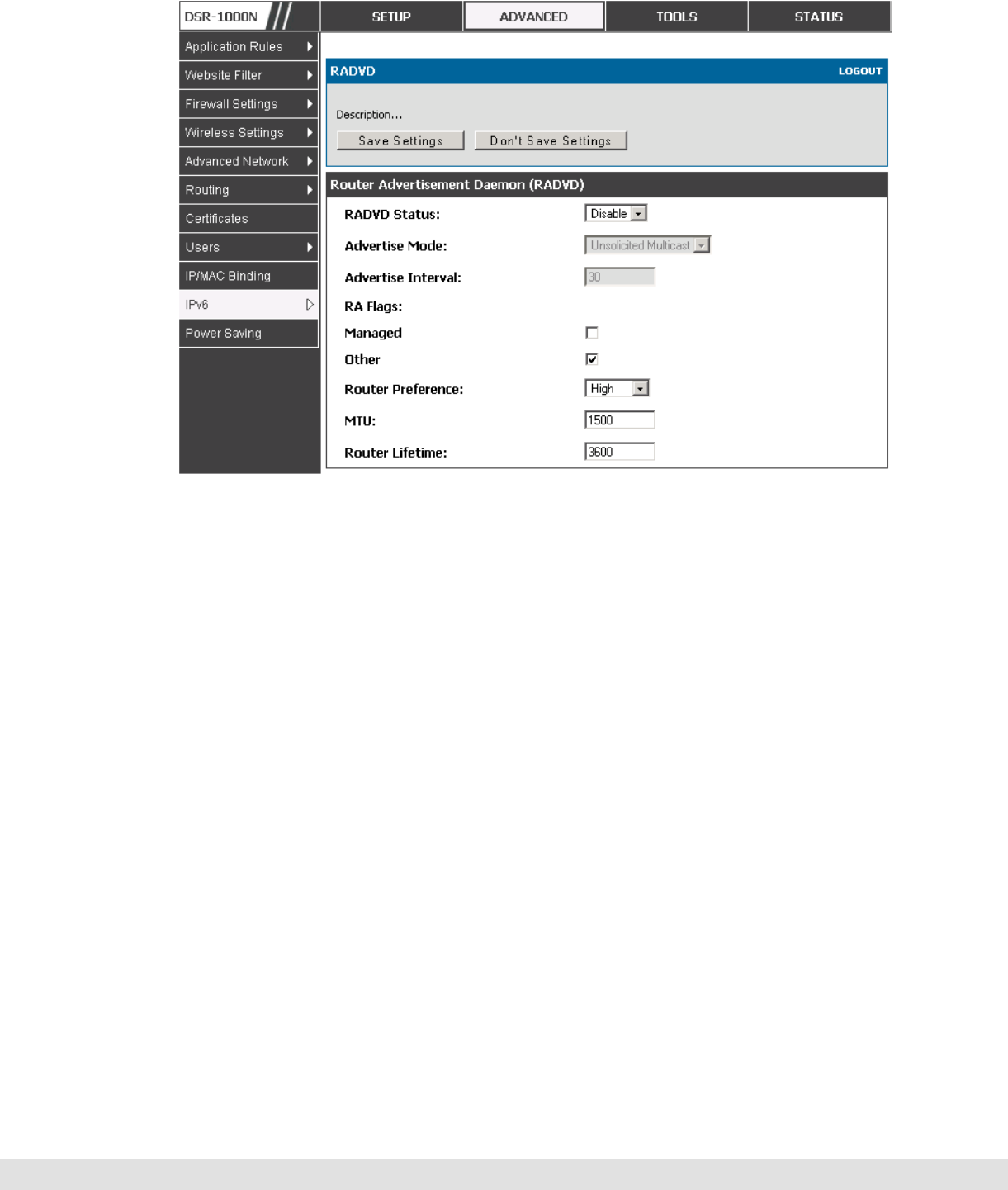
2.1.2.1 RADVD
Advanced > IPv6 > IPv6 LAN > Router Advertisement
To support stateless IPv6 auto configuration on the LAN, set the RADVD
status to Enable. The following settings are used to configure RADVD:
Advertise Mode: Select Unsolicited Multicast to send router advertisements
(RA’s) to all interfaces in the multicast group. To restrict RA’s to well known
IPv6 addresses on the LAN, and thereby reduce overall network traffic, select
Unicast only.

D-Link DSR Series Router
14
Advertise Interval: When advertisements are unsolicited multicast packets, this
interval sets the maximum time between advertisements from the interface.
The actual duration between advertisements is a random value between one
third of this field and this field. The default is 30 seconds.
RA Flags: The router advertisements (RA’s) can be sent with one or both of
these flags. Chose Managed to use the administered /stateful protocol for
address auto configuration. If the Other flag is selected the host uses
administered/stateful protocol for non-address auto configuration.
Router Preference: this low/medium/high parameter determines the preference
associated with the RADVD process of the router. This is useful if there are
other RADVD enabled devices on the LAN as it helps avoid conflicts for IPv6
clients.
MTU: The router advertisement will set this maximum transmission unit (MTU)
value for all nodes in the LAN that are autoconfigured by the router. The
default is 1500.
Router Lifetime: This value is present in RA’s and indicates the usefulness of
this router as a default router for the interface. The default is 3600 seconds.
Upon expiration of this value, a new RADVD exchange must take place
between the host and this router.
User Manual
15
Figure 3: Configuring the Router Advertisement Daemon
2.1.2.2
Advertisement Prefixes
Advanced > IPv6 > IPv6 LAN > Advertisement Prefixes
The router advertisements configured with advertisement prefixes allow this
router to inform hosts how to perform stateless address autoconfiguration.
Router advertisements contain a list of subnet prefixes that allow the router
to determine neighbors and whether the host is on the same link as the
router.
The following prefix options are available for the router advertisements:
IPv6 Prefix Type: To ensure hosts support IPv6 to IPv4 tunnel select the 6to4
prefix type. Selecting Global/Local/ISATAP will allow the nodes to support all
other IPv6 routing options

D-Link DSR Series Router
16
SLA ID: The SLA ID (Site-Level Aggregation Identifier) is available when 6to4
Prefixes are selected. This should be the interface ID of the router’s LAN
interface used for router advertisements.
IPv6 Prefix: When using Global/Local/ISATAP prefixes, this field is used to
define the IPv6 network advertised by this router.
IPv6 Prefix Length: This value indicates the number contiguous, higher order
bits of the IPv6 address that define up the network portion of the address.
Typically this is 64.
Prefix Lifetime: This defines the duration (in seconds) that the requesting node
is allowed to use the advertised prefix. It is analogous to DHCP lease time in
an IPv4 network.
Figure 4: IPv6 Advertisement Prefix settings
2.2 VLAN Configuration
The router supports virtual network isolation on the LAN with the use of
VLANs. LAN devices can be configured to communicate in a subnetwork
defined by VLAN identifiers. LAN ports can be assigned unique VLAN IDs so
that traffic to and from that physical port can be isolated from the general
User Manual
17
LAN. VLAN filtering is particularly useful to limit broadcast packets of a
device in a large network
VLAN support is disabled by default in the router. In the VLAN Configuration
page, enable VLAN support on the router and then proceed to the next
section to define the virtual network.
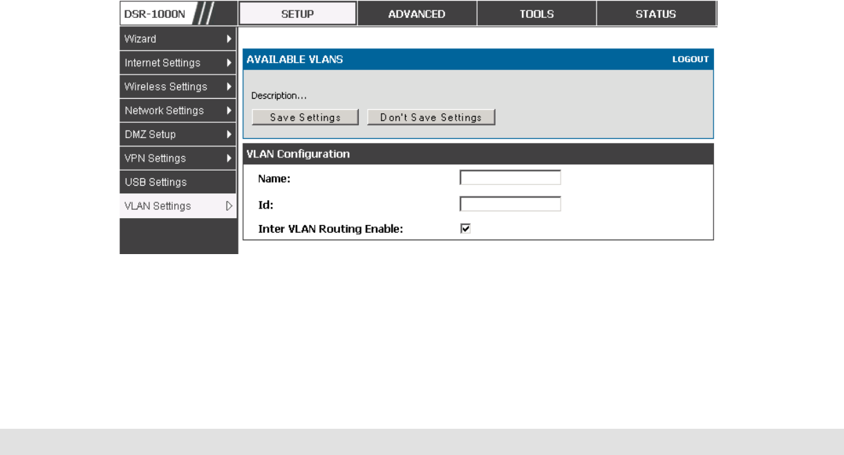
Setup > VLAN Settings > Available VLAN
The Available VLAN page shows a list of configured VLANs by name and
VLAN ID. A VLAN membership can be created by clicking the Add button
below the List of Available VLANs.
A VLAN membership entry consists of a VLAN identifier and the numerical
VLAN ID which is assigned to the VLAN membership. The VLAN ID value can
be any number from 2 to 4091. VLAN ID 1 is reserved for the default VLAN,
which is used for untagged frames received on the interface. VLAN IDs 4092
is reserved and cannot be used. By enabling Inter VLAN Routing, you will
allow traffic from LAN hosts belonging to this VLAN ID to pass through to
other configured VLAN IDs that have Inter VLAN Routing enabled.
Figure 5: Adding VLAN memberships to the LAN
D-Link DSR Series Router
18
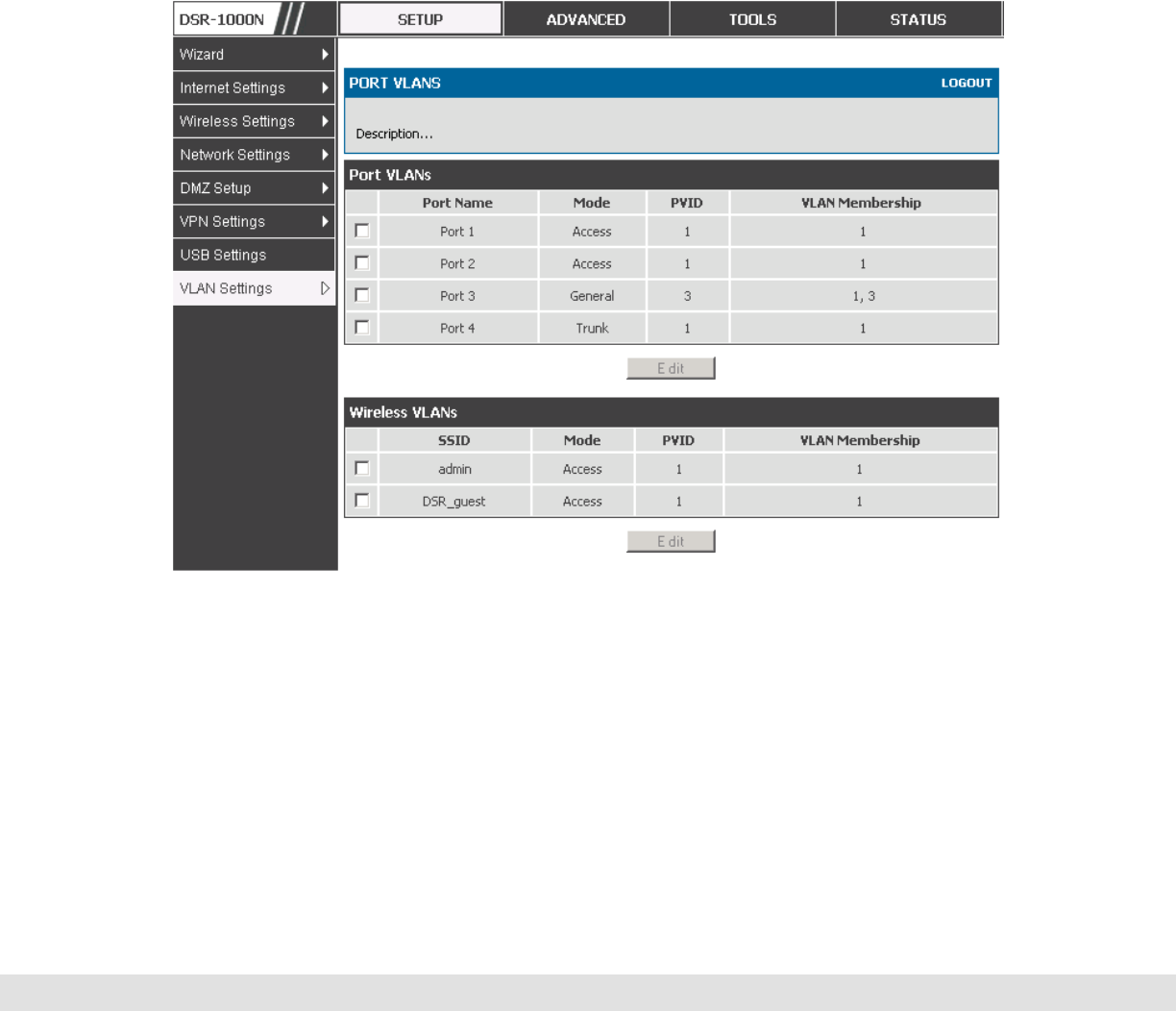
2.2.1 Associating VLANs to ports
In order to tag all traffic through a specific LAN port with a VLAN ID, you can
associate a VLAN to a physical port.
Setup > VLAN Settings > Port VLAN
VLAN membership properties for the LAN and wireless LAN are listed on this
page. The VLAN Port table displays the port identifier, the mode setting for
that port and VLAN membership information. The configuration page is
accessed by selecting one of the four physical ports or a configured access
point and clicking Edit.
Figure 6: Port VLAN list
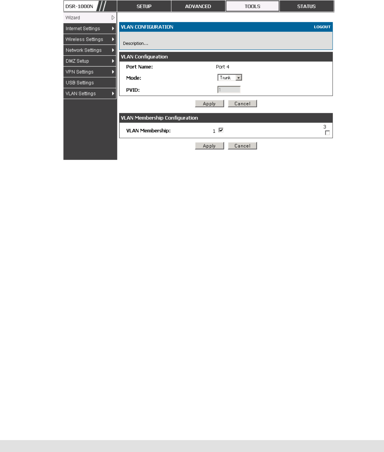
The edit page offers the following configuration options:
Mode: The mode of this VLAN can be General, Access, or Trunk. The default
is access.

User Manual
19
In General mode the port is a member of a user selectable set of VLANs.
The port sends and receives data that is tagged or untagged with a VLAN
ID. If the data into the port is untagged, it is assigned the defined PVID. In
the configuration from Figure 4, Port 3 is a General port with PVID 3, so
untagged data into Port 3 will be assigned PVID 3. All tagged data sent
out of the port with the same PVID will be untagged. This is mode is
typically used with IP Phones that have dual Ethernet ports. Data coming
from phone to the switch port on the router will be tagged. Data passing
through the phone from a connected device will be untagged.
In Access mode the port is a member of a single VLAN (and only one). All
data going into and out of the port is untagged. Traffic through a port in
access mode looks like any other Ethernet frame.
In Trunk mode the port is a member of a user selectable set of VLANs. All
data going into and out of the port is tagged. Untagged coming into the port
is not forwarded, except for the default VLAN with PVID=1, which is
untagged. Trunk ports multiplex traffic for multiple VLANs over the same
physical link.
Select PVID for the port when the General mode is selected.
Configured VLAN memberships will be displayed on the VLAN Membership
Configuration for the port. By selecting one more VLAN membership options
for a General or Trunk port, traffic can be routed between the selected VLAN
membership IDs
D-Link DSR Series Router
20
Figure 7: Configuring VLAN membership for a port
2.3 Configurable Port: DMZ Setup
This router supports one of the physical ports to be configured as a secondary
WAN Ethernet port or a dedicated DMZ port. A DMZ is a subnetwork that is
open to the public but behind the firewall. The DMZ adds an additional layer
of security to the LAN, as specific services/ports that are exposed to the
internet on the DMZ do not have to be exposed on the LAN. It is
recommended that hosts that must be exposed to the internet (such as web or
email servers) be placed in the DMZ network. Firewall rules can be allowed
to permit access specific services/ports to the DMZ from both the LAN or
WAN. In the event of an attack to any of the DMZ nodes, the LAN is not
necessarily vulnerable as well.
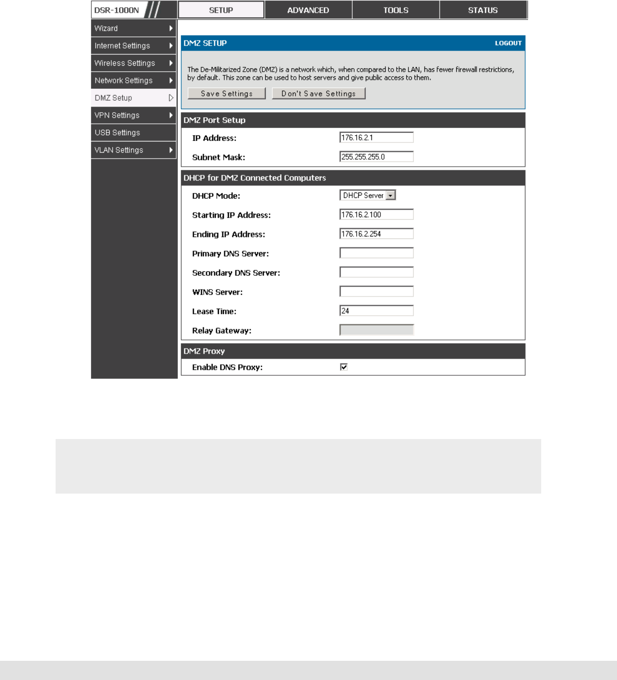
Setup > DMZ Setup > DMZ Setup Configuration
DMZ configuration is identical to the LAN configuration. There are no
restrictions on the IP address or subnet assigned to the DMZ port, other than
User Manual
21
the fact that it cannot be identical to the IP address given to the LAN interface
of this gateway.
Figure 8: DMZ configuration
In order to configure a DMZ port, the router’s configurable port must be set
to DMZ in the Setup > Internet Settings > Configurable Port page.
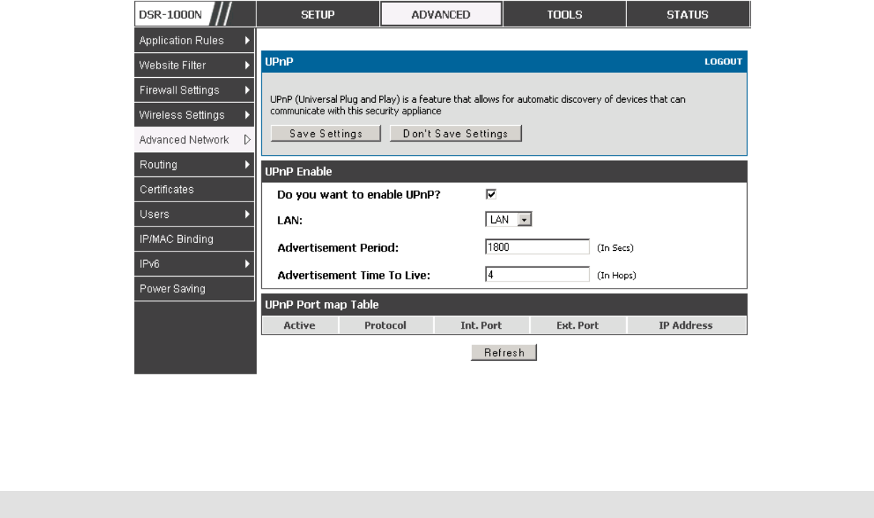
2.4 Universal Plug and Play (UPnP)
Advanced > Advanced Network > UPnP
D-Link DSR Series Router
22
Universal Plug and Play (UPnP) is a feature that allows the router to
discovery devices on the network that can communicate with the router and
allow for auto configuration. If a network device is detected by UPnP, the
router can open internal or external ports for the traffic protocol required by
that network device.
Once UPnP is enabled, you can configure the router to detect UPnP-
supporting devices on the LAN (or a configured VLAN). If disabled, the
router will not allow for automatic device configuration.
Configure the following settings to use UPnP:
Advertisement Period: This is the frequency that the router broadcasts UPnP
information over the network. A large value will minimize network traffic but
cause delays in identifying new UPnP devices to the network.
Advertisement Time to Live: This is expressed in hops for each UPnP packet.
This is the number of steps a packet is allowed to propagate before being
discarded. Small values will limit the UPnP broadcast range. A default of 4 is
typical for networks with few switches.

User Manual
23
Figure 9: UPnP Configuration
UPnP Port map Table
The UPnP Port map Table has the details of UPnP devices that respond to
the router’s advertisements. The following information is displayed for each
detected device:
Active: A yes/no indicating whether the port of the UPnP device that established
a connection is currently active
Protocol: The network protocol (i.e. HTTP, FTP, etc.) used by the device
Int. Port (Internal Port): The internal ports opened by UPnP (if any)
Ext. Port (External Port): The external ports opened by UPnP (if any)
IP Address: The IP address of the UPnP device detected by this router
Click Refresh to refresh the portmap table and search for any new UPnP
devices.
D-Link DSR Series Router
24
3. Connecting to the Internet: WAN Setup
This router has two WAN ports that can be used to establish a connection to the
internet. The following ISP connection types are supported: DHCP, Static, PPPoE,
PPTP, L2TP, 3G Internet (via USB modem).
It is assumed that you have arranged for internet service with your Internet Service
Provider (ISP). Please contact your ISP or network administrator for the
configuration information that will be required to setup the router.
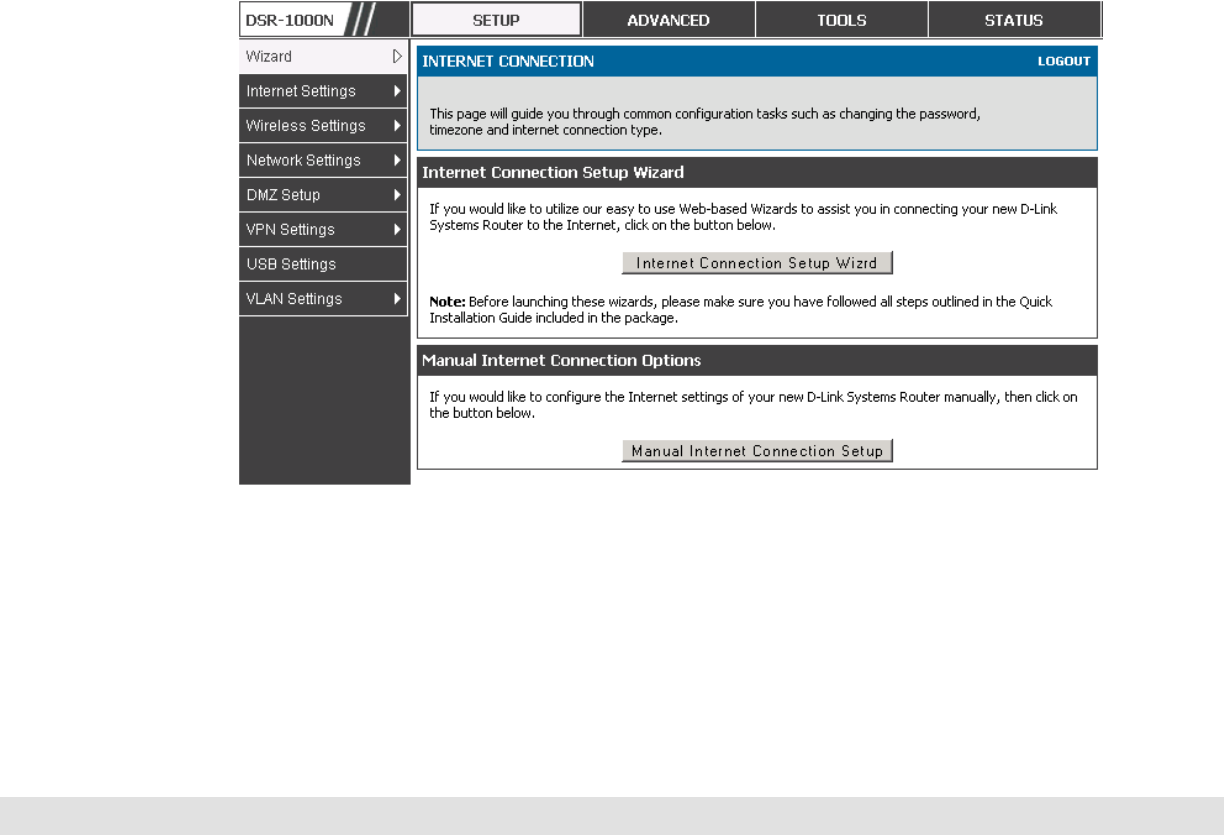
3.1 Internet Setup Wizard
Setup > Wizard > Internet
The Internet Connection Setup Wizard is available for users new to
networking. By going through a few straightforward configuration pages you
can take the information provided by your ISP to get your WAN connection up
and enable internet access for your network.
Figure 10: Internet Connection Setup Wizard
You can start using the Wizard by logging in with the administrator password
for the router. Once authenticated set the time zone that you are located in,

User Manual
25
and then choose the type of ISP connection type: DHCP, Static, PPPoE,
PPTP, L2TP. Depending on the connection type a username/password may
be required to register this router with the ISP. In most cases the default
settings can be used if the ISP did not specify that parameter. The last step
in the Wizard is to click the Connect button, which confirms the settings by
establishing a link with the ISP. Once connected, you can move on and
configure other features in this router.
3G Internet access with a USB modem is supported on the secondary WAN
port (WAN2). The Internet Connection Setup Wizard assists with the
primary WAN port (WAN1) configuration only.
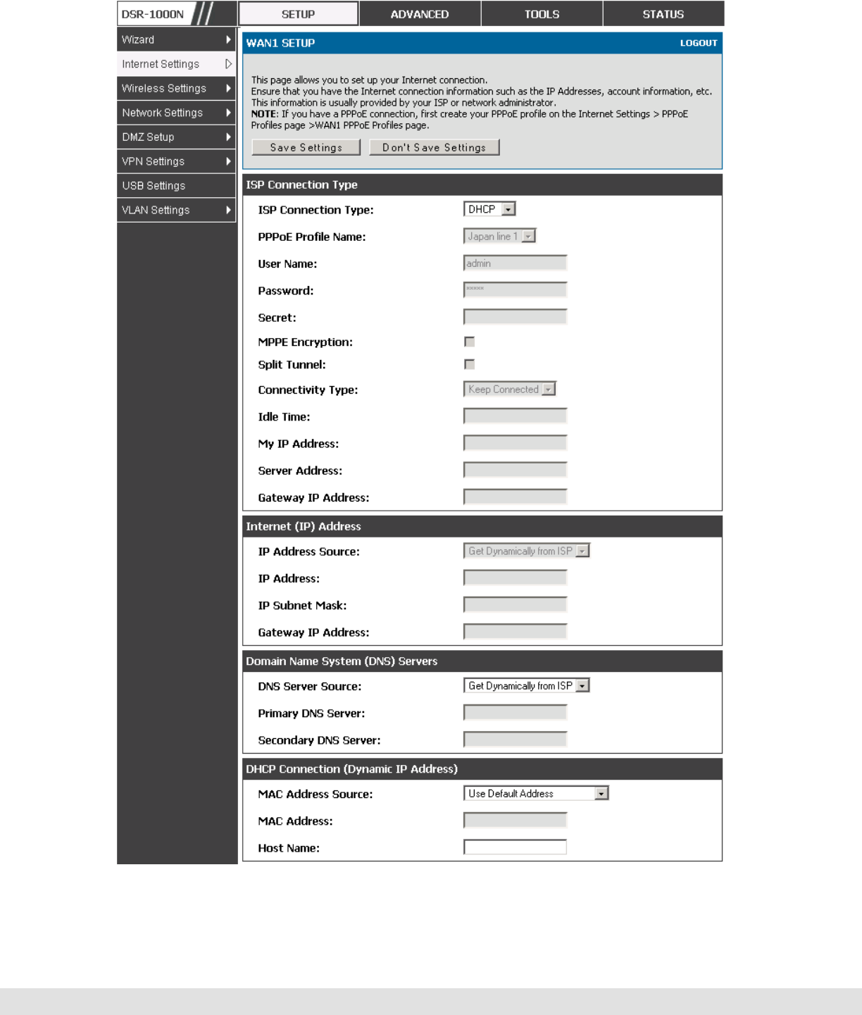
3.2 WAN Configuration
Setup > Internet Settings > WAN1 Setup
You must either allow the router to detect WAN connection type automatically
or configure manually the following basic settings to enable Internet
connectivity:
ISP Connection type: Based on the ISP you have selected for the primary
WAN link for this router, choose Static IP address, DHCP client, Point-to-
Point Tunneling Protocol (PPTP), Point-to-Point Protocol over Ethernet
(PPPoE), Layer 2 Tunneling Protocol (L2TP). Required fields for the selected
ISP type become highlighted. Enter the following information as needed and
as provided by your ISP:
PPPoE Profile Name. This menu lists configured PPPoE profiles, particularly
useful when configuring multiple PPPoE connections (i.e. for Japan ISPs that
have multiple PPPoE support).
ISP login information. This is required for PPTP and L2TP ISPs.
User Name
Password
Secret (required for L2TP only)

D-Link DSR Series Router
26
MPPE Encryption: For PPTP links, your ISP may require you to enable
Microsoft Point-to-Point Encryption (MPPE).
Split Tunnel (supported for PPTP and L2TP connection). This setting allows
your LAN hosts to access internet sites over this WAN link while still
permitting VPN traffic to be directed to a VPN configured on this WAN port.
With split tunneling enabled users can bypass content filtering and other
firewall settings. Disable split tunneling on the WAN interface for highest
gateway security measures.
Connectivity Type. To keep the connection always on, click Keep Connected.
To log out after the connection is idle for a period of time (useful if your ISP
costs are based on logon times), click Idle Timeout and enter the time, in
minutes, to wait before disconnecting in the Idle Time field.
My IP Address: Enter the IP address assigned to you by the ISP.
Server IP Address: Enter the IP address of the PPTP or L2TP server.
WAN Port IP address
Your ISP assigns you an IP address that is either dynamic (newly generated
each time you log in) or static (permanent). The IP Address Source option
allows you to define whether the address is statically provided by the ISP or
should be received dynamically at each login. If static, enter your IP address,
IPv4 subnet mask, and the ISP gateway’s IP address. PPTP and L2TP ISPs
also can provide a static IP address and subnet to configure, however the
default is to receive that information dynamically from the ISP.
WAN DNS Servers
The IP Addresses of WAN Domain Name Servers (DNS) are typically provided
dynamically from the ISP but in some cases you can define the static IP
addresses of the DNS servers. DNS servers map Internet domain names
(example: www.google.com) to IP addresses. Click to indicate whether to get
DNS server addresses automatically from your ISP or to use ISP-specified

User Manual
27
addresses. If the latter, enter addresses for the primary and secondary DNS
servers. To avoid connectivity problems, ensure that you enter the addresses
correctly.
DHCP WAN
For DHCP client connections, you can choose the MAC address of the router
to register with the ISP. In some cases you may need to clone the LAN host’s
MAC address if the ISP is registered with that LAN host.
D-Link DSR Series Router
28
Figure 11: Manual WAN configuration
User Manual
29
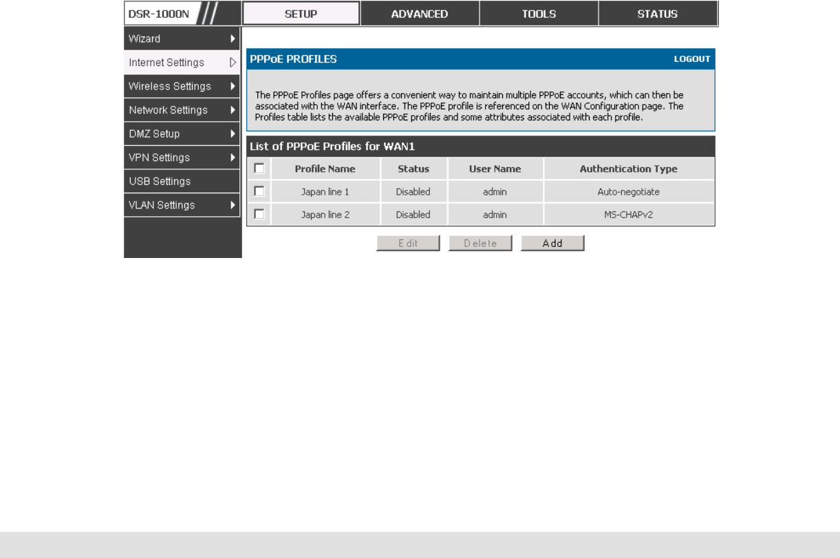
3.2.1 PPPoE Profiles
Setup > Internet Settings > PPPoE Profiles > WAN1 PPPoE Profiles
Some ISP’s allow for multiple concurrent PPPoE sessions (it is most
common in Japan). Each connection can have its own specific
authentication requirements and will provide unique IP, gateway, and DNS
address parameters to the associated WAN port.
The PPPoE Profiles page offers a convenient way to maintain multiple
PPPoE accounts, which can then be associated with one of the available
WAN interfaces. Once configured, a PPPoE profile name can be selected
on the WAN configuration page to reduce the configuration requirements for
that WAN port.
The PPPoE profile is referenced on the WAN Configuration page. The List of
PPPoE profiles for a particular WAN (see figure below) outlines the available
profile and their status and authentication type.
Figure 12: List of configured PPPoE profiles
To create a new PPPoE profile, select Add in the PPPoE Profile page. Each
profile is associated to one of the two WAN ports. Similar to the PPPoE
configuration options in the WAN configuration page, you need to define the
ISP logon credentials, authentication type, and connectivity settings for the
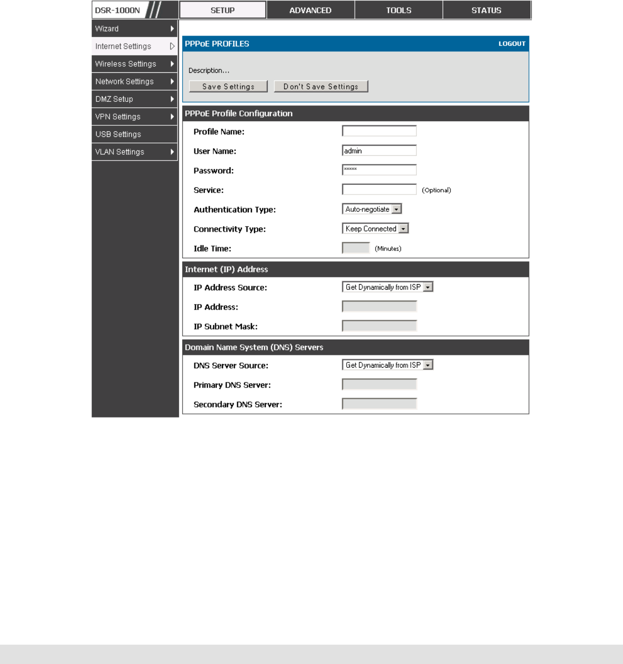
D-Link DSR Series Router
30
PPPoE session. This information will be provided by the ISP that offers
multiple PPPoE session support.
Figure 13: PPPoE profile configuration
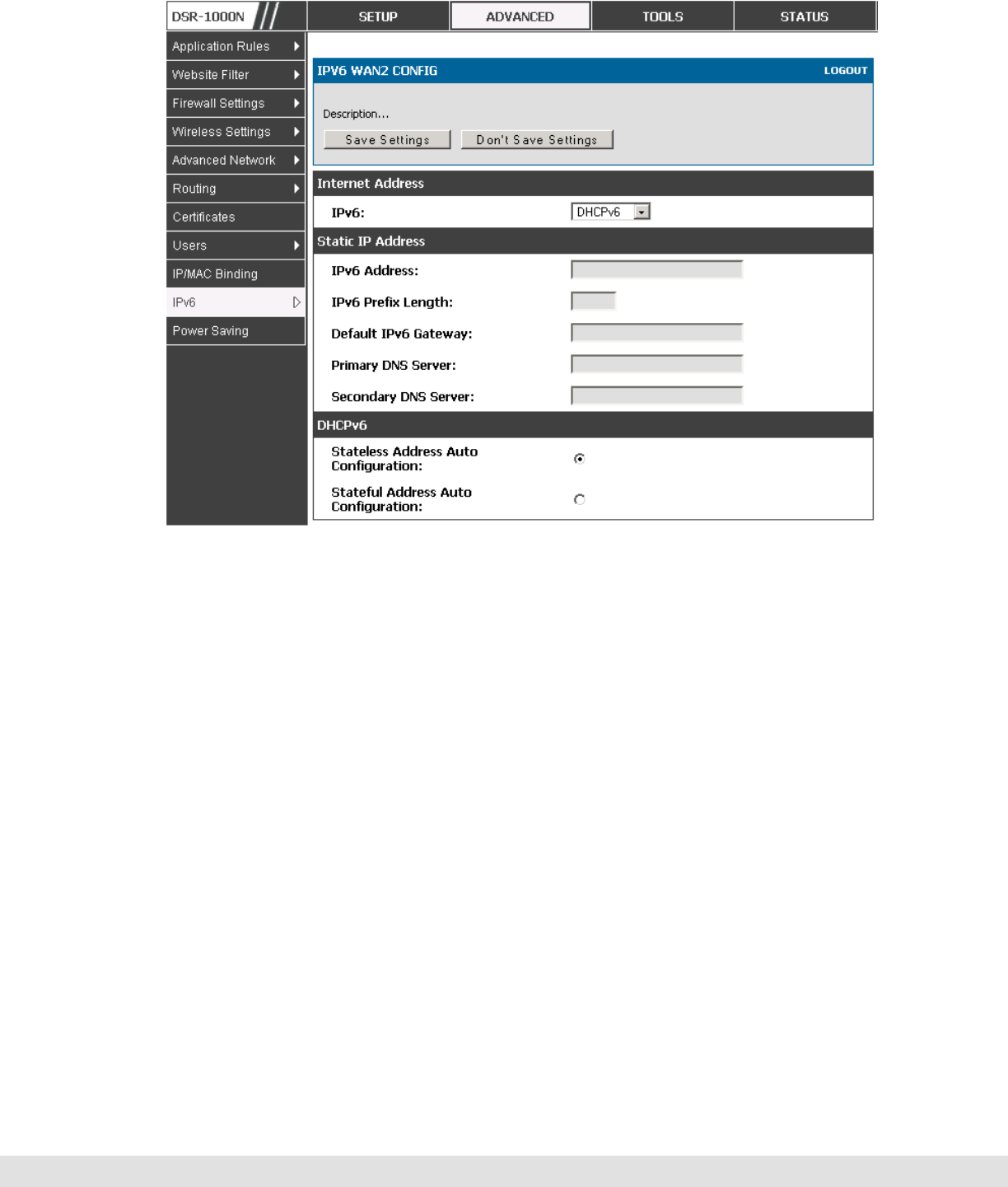
3.2.2 WAN Configuration in an IPv6 Network
Setup > IPv6 > IPv6 WAN1 Config
For IPv6 WAN connections, this router can have a static IPv6 address or
receive connection information when configured as a DHCPv6 client. In the
case where the ISP assigns you a fixed address to access the internet, the

User Manual
31
static configuration settings must be completed. In addition to the IPv6
address assigned to your router, the IPv6 prefix length defined by the ISP is
needed. The default IPv6 Gateway address is the server at the ISP that this
router will connect to for accessing the internet. The primary and secondary
DNS servers on the ISP’s IPv6 network are used for resolving internet
addresses, and these are provided along with the static IP address and
prefix length from the ISP.
When the ISP allows you to obtain the WAN IP settings via DHCP, you need
to provide details for the DHCPv6 client configuration. The DHCPv6 client
on the gateway can be either stateless or stateful. If a stateful client is
selected the gateway will connect to the ISP’s DHCPv6 server for a leased
address. For stateless DHCP there need not be a DHCPv6 server available
at the ISP, rather ICMPv6 discover messages will originate from this
gateway and will be used for auto configuration. A third option to specify the
IP address and prefix length of a preferred DHCPv6 server is available as
well.
D-Link DSR Series Router
32
Figure 14: IPv6 WAN Setup page
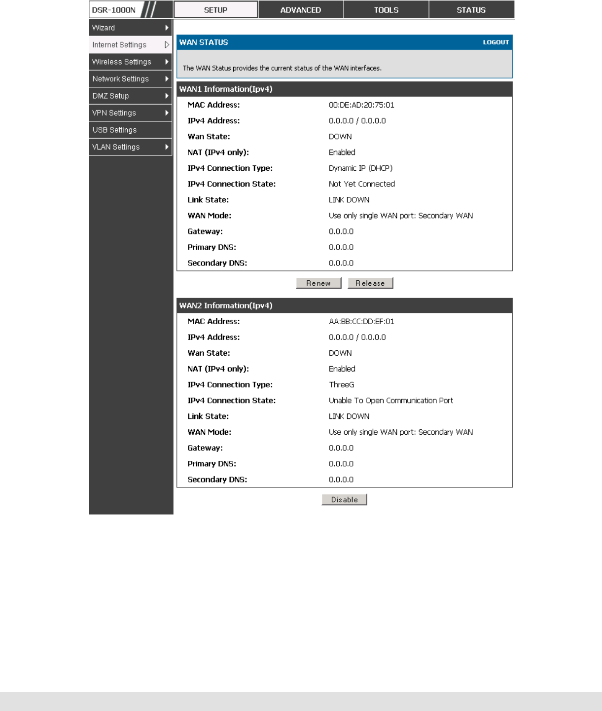
3.2.3 Checking WAN Status
Setup > Internet Settings > WAN Status
The status and summary of configured settings for both WAN1 and WAN2 are
available on the WAN Status page. You can view the following key
connection status information for each WAN port:
Connection time
Connection type: dynamic IP or static IP
Connection state: This is whether the WAN is connected or disconnected to an
ISP. The Link State is whether the physical WAN connection in place; the Link
State can be UP (i.e. cable inserted) while the WAN Connection State is down.
IP address / subnet mask
Gateway IP address
User Manual
33
Figure 15: Connection Status information for both WAN ports
The WAN status page allows you to Enable or Disable static WAN links. For
WAN settings that are dynamically received from the ISP, you can Renew or
Release the link parameters if required.
D-Link DSR Series Router
34
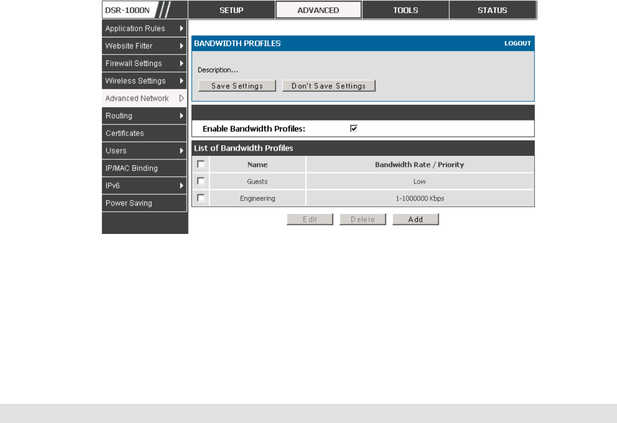
3.3 Bandwidth Controls
Advanced > Advanced Network > Traffic Management > Bandwidth
Profiles
Bandwidth profiles allow you to regulate the traffic flow from the LAN to WAN
1 or WAN 2. This is useful to ensure that low priority LAN users (like guests
or HTTP service) does not monopolize the available WAN’s bandwidth for
cost-savings or bandwidth-priority-allocation purposes.
Bandwidth profiles configuration consists of enabling the bandwidth control
feature from the GUI and adding a profile which defines the control
parameters. The profile can then be associated with a traffic selector, so that
bandwidth profile can be applied to the traffic matching the selectors.
Selectors are elements like IP addresses or services that would trigger the
configured bandwidth regulation.
Figure 16: List of Configured Bandwidth Profiles
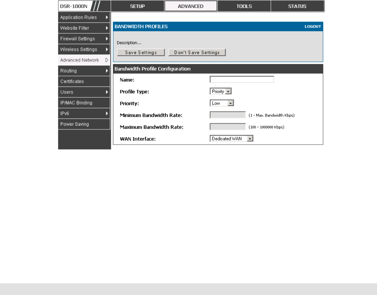
To create a new bandwidth profile, click Add in the List of Bandwidth
Profiles. The following configuration parameters are used to define a
bandwidth profile:
User Manual
35
Profile Name: This identifier is used to associate the configured profile to the
traffic selector
You can choose to limit the bandwidth either using priority or rate.
• If using priority “Low”, “High”, “Medium” can be selected. If there is a low
priority profile associated with traffic selector A and a high priority profile
associated with traffic selector B, then the WAN bandwidth allocation
preference will be to traffic selector B packets.
• For finer control, the Rate profile type can be used. With this option the
minimum and maximum bandwidth allowed by this profile can be limited.
Choose the WAN interface that the profile should be associated with
Figure 17: Bandwidth Profile Configuration page
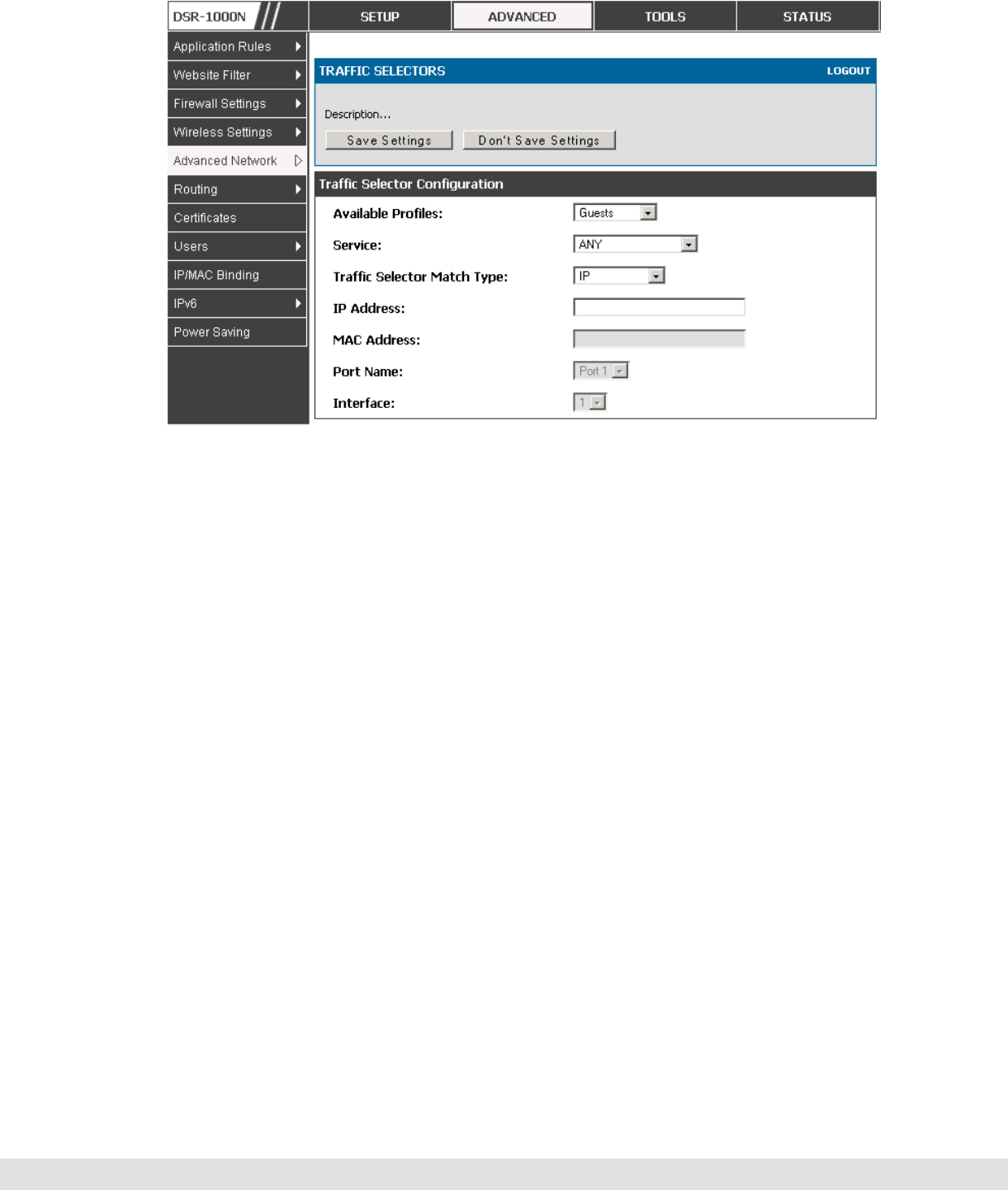
Advanced > Advanced Network > Traffic Management > Traffic
Selectors
Once a profile has been created it can then be associated with a traffic flow
from the LAN to WAN. To create a traffic selector, click Add on the Traffic

D-Link DSR Series Router
36
Selectors page. Traffic selector configuration binds a bandwidth profile to a
type or source of LAN traffic with the following settings:
Available profiles: Assign one of the defined bandwidth profiles
Service: You can have the selected bandwidth regulation apply to a specific
service (i.e. FTP) from the LAN. If you do not see a service that you want, you
can configure a custom service through the Advanced > Firewall Settings
> Custom Services page. To have the profile apply to all services, select
ANY.
Traffic Selector Match Type: this defines the parameter to filter against when
applying the bandwidth profile. A specific machine on the LAN can be
identified via IP address or MAC address, or the profile can apply to a LAN
port or VLAN group. As well a wireless network can be selected by its BSSID
for bandwidth shaping.
User Manual
37
Figure 18: Traffic Selector Configuration
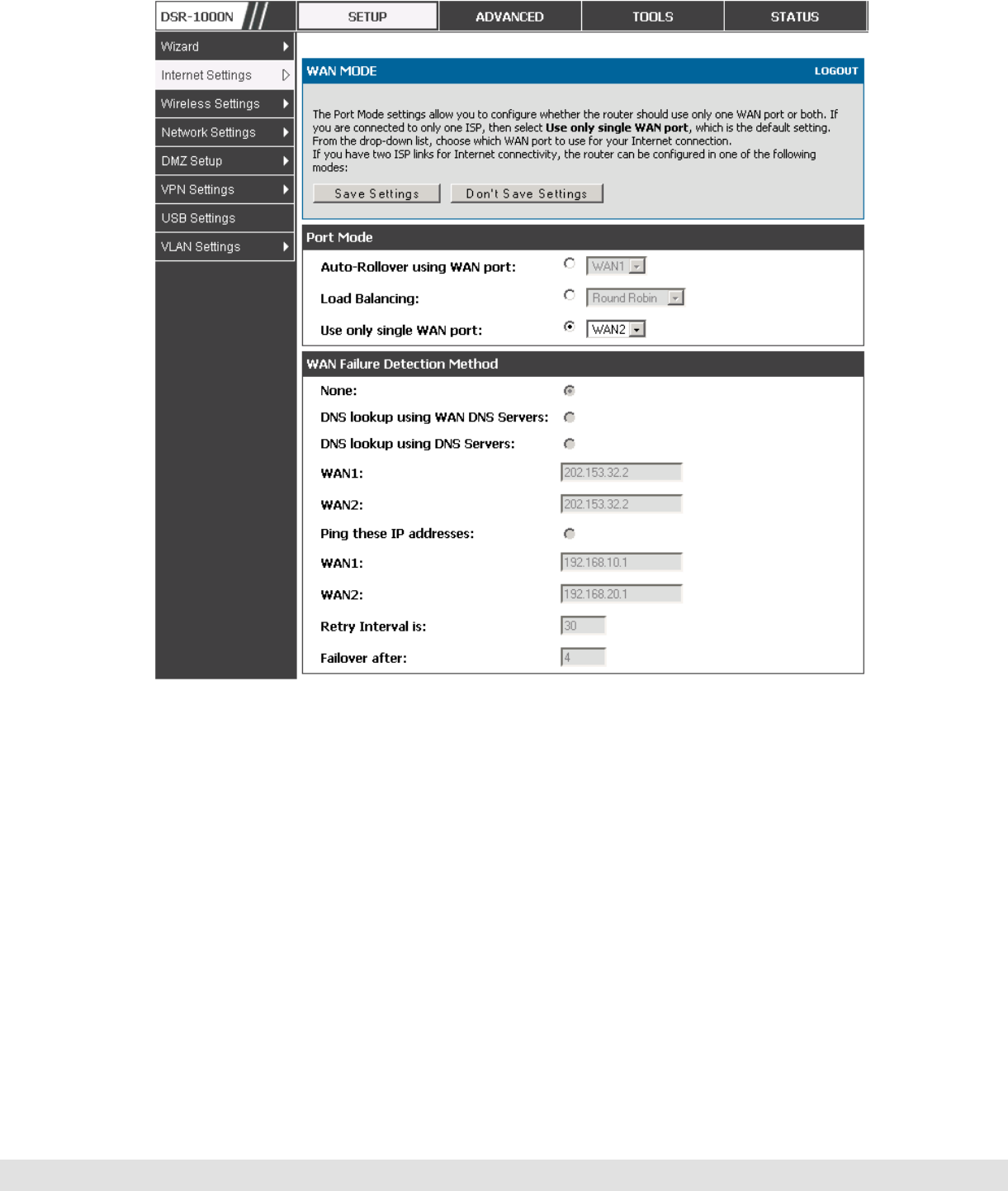
3.4 Features with Multiple WAN Links
This router supports multiple WAN links. This allows you to take advantage
of failover and load balancing features to ensure certain internet dependent
services are prioritized in the event of unstable WAN connectivity on one of
the ports.
Setup > Internet Settings > WAN Mode
To use Auto Failover or Load Balancing, WAN link failure detection must be
configured. This involves accessing DNS servers on the internet or ping to
an internet address (user defined). If required, you can configure the
number of retry attempts when the link seems to be disconnected or the
threshold of failures that determines if a WAN port is down.
3.4.1 Auto Failover
In this case one of your WAN ports is assigned as the primary internet link
for all internet traffic. The secondary WAN port is used for redundancy in
case the primary link goes down for any reason. Both WAN ports (primary
and secondary) must be configured to connect to the respective ISP’s before

D-Link DSR Series Router
38
enabling this feature. The secondary WAN port will remain unconnected
until a failure is detected on the primary link (either port can be assigned as
the primary). In the event of a failure on the primary port, all internet traffic
will be rolled over to the backup port. When configured in Auto Failover
mode, the link status of the primary WAN port is checked at regular intervals
as defined by the failure detection settings.
3.4.2 Load Balancing
This feature allows you to use multiple WAN links (and presumably multiple
ISP’s) simultaneously. After configuring more than one WAN port, the load
balancing option is available to carry traffic over more than one link.
Protocol bindings are used to segregate and assign services over one WAN
port in order to manage internet flow. The configured failure detection
method is used at regular intervals on all configured WAN ports when in
Load Balancing mode.
Load balancing is particularly useful when the connection speed of one WAN
port greatly differs from another. In this case you can define protocol
bindings to route low-latency services (such as VOIP) over the higher-speed
link and let low-volume background traffic (such as SMPT) go over the lower
speed link.
User Manual
39
Figure 19: Load Balancing is available when multiple WAN ports are
configured and Protocol Bindings have been defined
3.4.3 Protocol Bindings
Advanced > Routing > Protocol Bindings
Protocol bindings are required when the Load Balancing feature is in use.
Choosing from a list of configured services or any of the user-defined
services, the type of traffic can be assigned to go over only one of the
available WAN ports. For increased flexibility the source network or
machines can be specified as well as the destination network or machines.
For example the VOIP traffic for a set of LAN IP addresses can be assigned
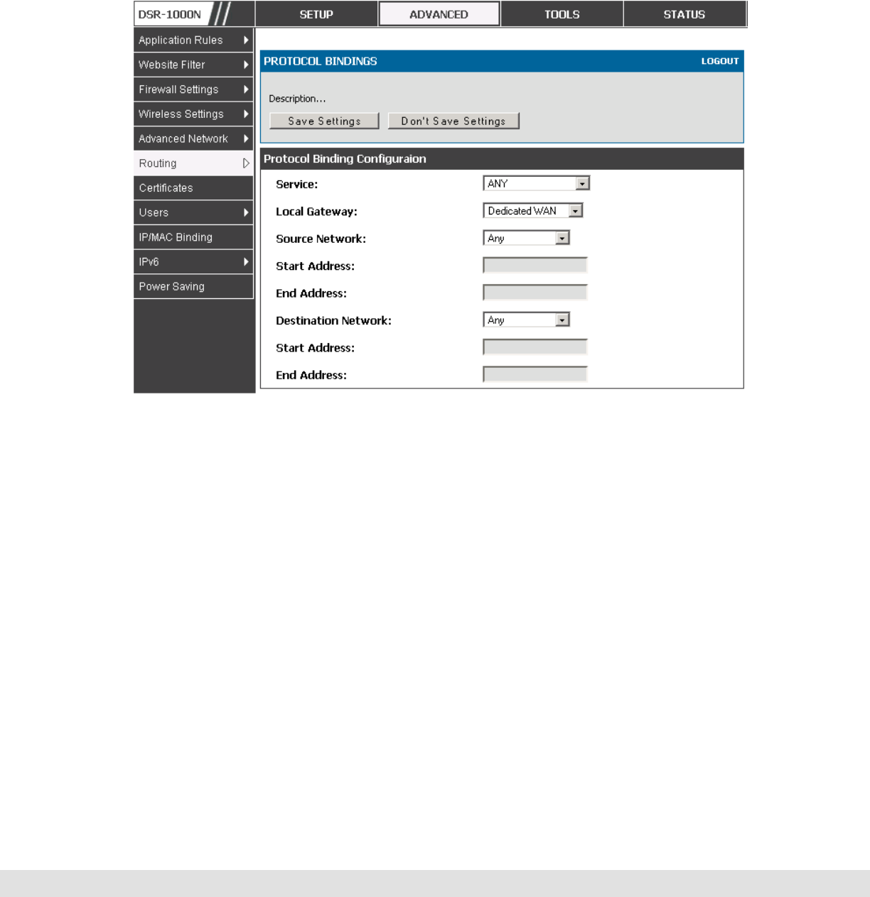
D-Link DSR Series Router
40
to one WAN and any VIOP traffic from the remaining IP addresses can be
assigned to the other WAN link. Protocol bindings are only applicable when
load balancing mode is enabled and more than one WAN is configured.
Figure 20: Protocol binding setup to associate a service and/or LAN source
to a WAN and/or destination network
3.5 Routing Configuration
Routing between the LAN and WAN will impact the way this router handles
traffic that is received on any of its physical interfaces. The routing mode of
the gateway is core to the behavior of the traffic flow between the secure LAN
and the internet.
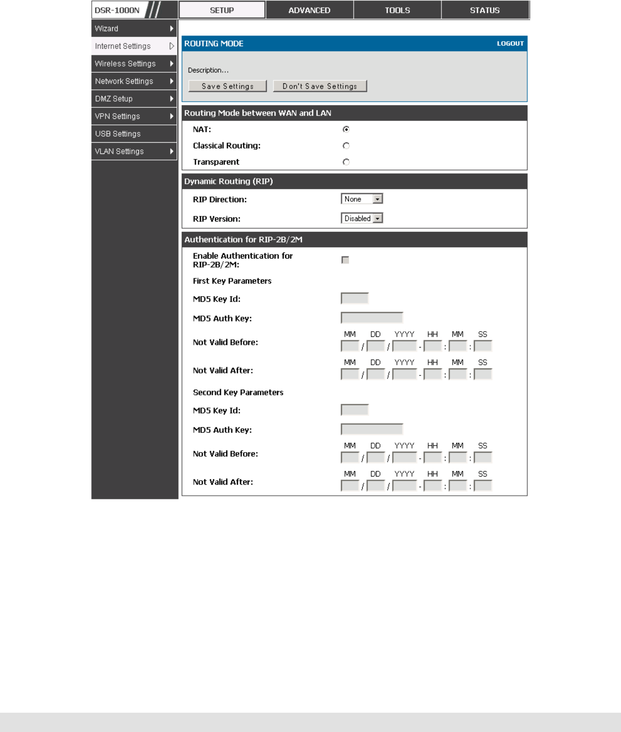
3.5.1 Routing Mode
Setup > Internet Settings > Routing Mode
This device supports classical routing, network address translation (NAT),
and transport mode routing.

User Manual
41
With classical routing, devices on the LAN can be directly accessed from
the internet by their public IP addresses (assuming appropriate firewall
settings). If your ISP has assigned an IP address for each of the
computers that you use, select Classic Routing.
NAT is a technique which allows several computers on a LAN to share an
Internet connection. The computers on the LAN use a "private" IP address
range while the WAN port on the router is configured with a single "public"
IP address. Along with connection sharing, NAT also hides internal IP
addresses from the computers on the Internet. NAT is required if your
ISP has assigned only one IP address to you. The computers that connect
through the router will need to be assigned IP addresses from a private
subnet.
Transparent mode routing between the LAN and WAN does not perform
NAT. Broadcast and multicast packets that arrive on the LAN interface
are switched to the WAN and vice versa, if they do not get filtered by
firewall or VPN policies. If the LAN and WAN are in the same broadcast
domain, select Transparent mode.
D-Link DSR Series Router
42
Figure 21: The Routing Mode page is used to configure the device’s routing
between WAN and LAN, as well as Dynamic routing (RIP)
3.5.2 Dynamic Routing (RIP)
Setup > Internet Settings > Routing Mode
Dynamic routing using the Routing Information Protocol (RIP) is an Interior
Gateway Protocol (IGP) that is common in LANs. With RIP this router can
exchange routing information with other supported routers in the LAN and

User Manual
43
allow for dynamic adjustment of routing tables in order to adapt to
modifications in the LAN without interrupting traffic flow.
The RIP direction will define how this router sends and receives RIP
packets. Choose between:
Both: The router both broadcasts its routing table and also processes RIP
information received from other routers. This is the recommended setting in
order to fully utilize RIP capabilities.
Out Only: The router broadcasts its routing table periodically but does not
accept RIP information from other routers.
In Only: The router accepts RIP information from other routers, but does not
broadcast its routing table.
None: The router neither broadcasts its route table nor does it accept any RIP
packets from other routers. This effectively disables RIP.
The RIP version is dependent on the RIP support of other routing devices in
the LAN.
Disabled: This is the setting when RIP is disabled.
RIP-1 is a class-based routing version that does not include subnet information.
This is the most commonly supported version.
RIP-2 includes all the functionality of RIPv1 plus it supports subnet information.
Though the data is sent in RIP-2 format for both RIP-2B and RIP-2M, the
mode in which packets are sent is different. RIP-2B broadcasts data in the
entire subnet while RIP-2M sends data to multicast addresses.
If RIP-2B or RIP-2M is the selected version, authentication between this
router and other routers (configured with the same RIP version) is required.
MD5 authentication is used in a first/second key exchange process. The
authentication key validity lifetimes are configurable to ensure that the
routing information exchange is with current and supported routers detected
on the LAN.

D-Link DSR Series Router
44
3.5.3 Static Routing
Advanced > Routing > Static Routing
Advanced > IPv6 > IPv6 Static Routing
Manually adding static routes to this device allows you to define the path
selection of traffic from one interface to another. There is no communication
between this router and other devices to account for changes in the path;
once configured the static route will be active and effective until the network
changes.
The List of Static Routes displays all routes that have been added manually
by an administrator and allows several operations on the static routes. The
List of IPv4 Static Routes and List of IPv6 Static Routes share the same
fields (with one exception):
Name: Name of the route, for identification and management.
Active: Determines whether the route is active or inactive. A route can be added
to the table and made inactive, if not needed. This allows routes to be used as
needed without deleting and re-adding the entry. An inactive route is not
broadcast if RIP is enabled.
Private: Determines whether the route can be shared with other routers when
RIP is enabled. If the route is made private, then the route will not be shared in
a RIP broadcast or multicast. This is only applicable for IPv4 static routes.
Destination: the route will lead to this destination host or IP address.
IP Subnet Mask: This is valid for IPv4 networks only, and identifies the subnet
that is affected by this static route
Interface: The physical network interface (WAN1, WAN2, DMZ or LAN), through
which this route is accessible.
Gateway: IP address of the gateway through which the destination host or
network can be reached.
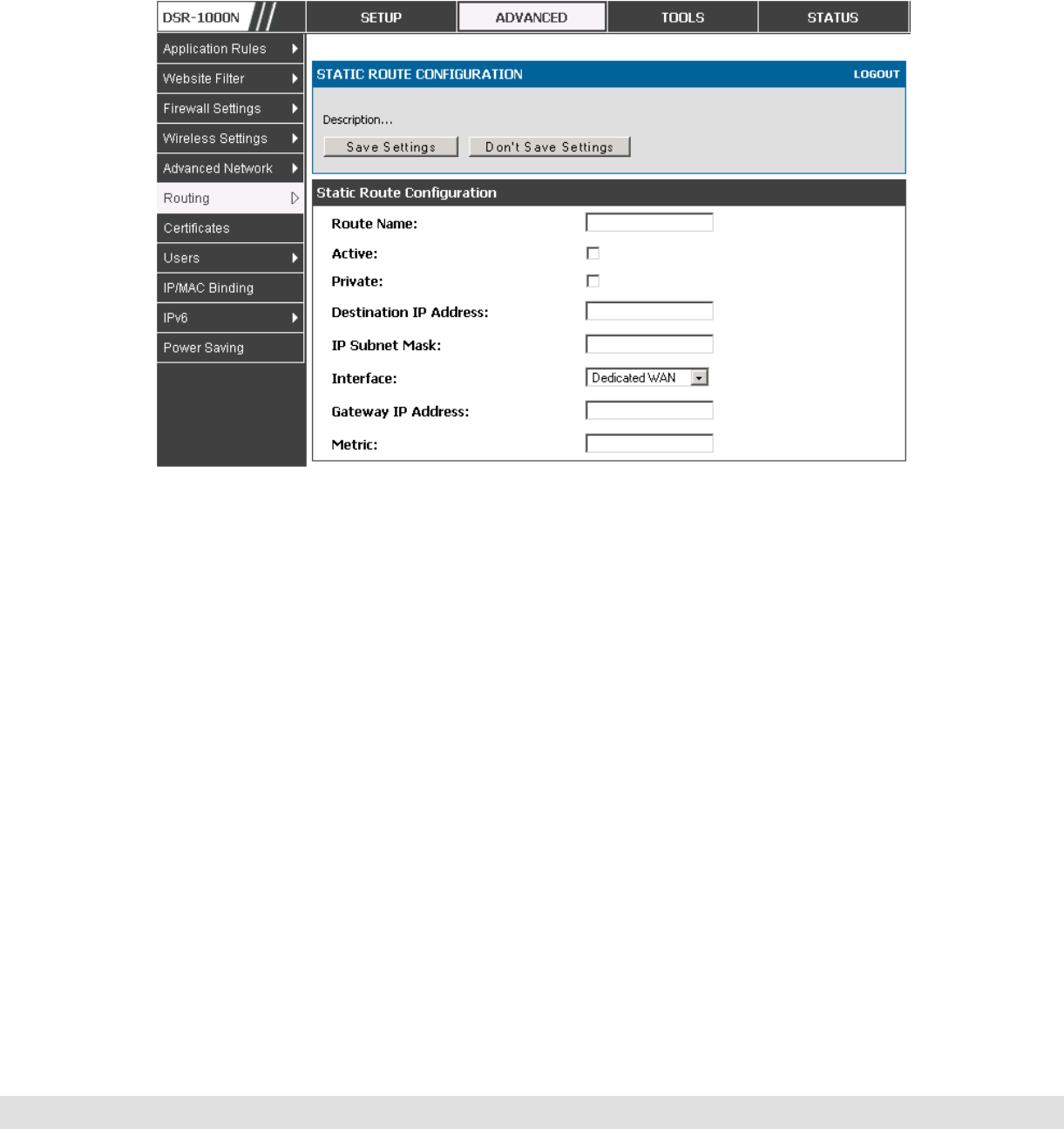
User Manual
45
Metric: Determines the priority of the route. If multiple routes to the same
destination exist, the route with the lowest metric is chosen.
Figure 22: Static route configuration fields
3.6 Configurable Port - WAN Option
This router supports one of the physical ports to be configured as a secondary
WAN Ethernet port or a dedicated DMZ port. If the port is selected to be a
secondary WAN interface, all configuration pages relating to WAN2 are
enabled.
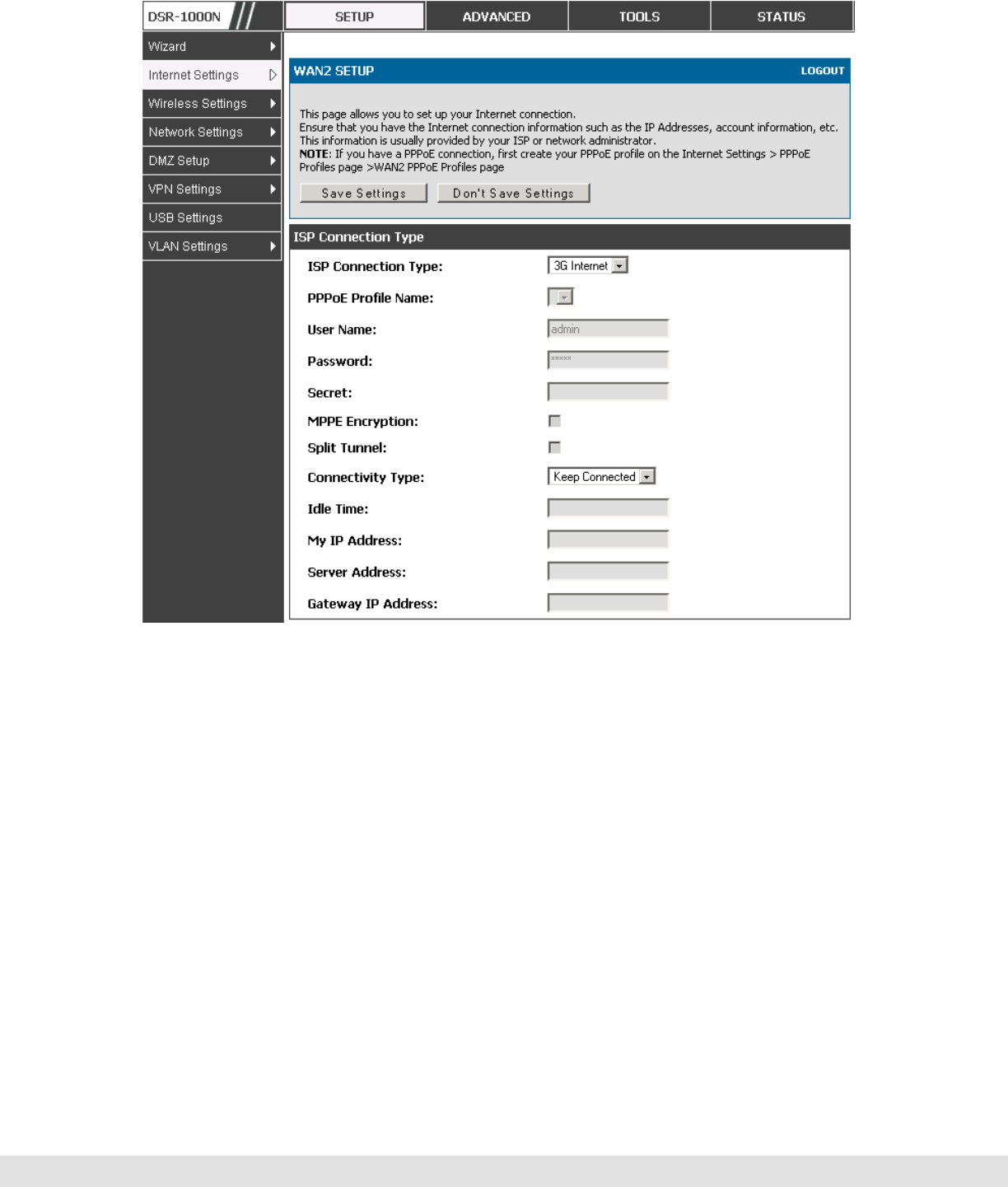
Setup > Internet Settings > WAN2 Setup
WAN2 configuration is identical to the WAN1 configuration with one significant
exception: configuration for the 3G USB modem is available only on WAN2.
D-Link DSR Series Router
46
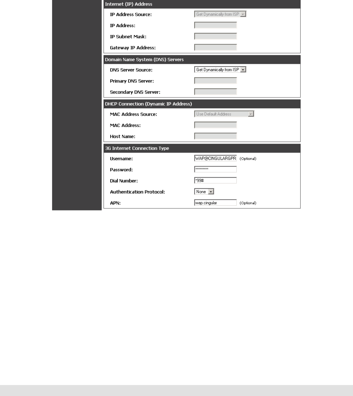
Figure 23: WAN2 configuration for 3G internet (part 1)
Cellular 3G internet access is available on WAN2 via a USB modem. The
cellular ISP that provides the 3G data plan will provide the authentication
requirements to establish a connection. The dial Number and APN are
specific to the cellular carriers. Once the connection type settings are
configured and saved, navigate to the WAN status page (Setup > Internet
Settings > WAN Status) and Enable the WAN2 link to establish the 3G
connection.
User Manual
47
Figure 24: WAN2 configuration for 3G internet (part 2)
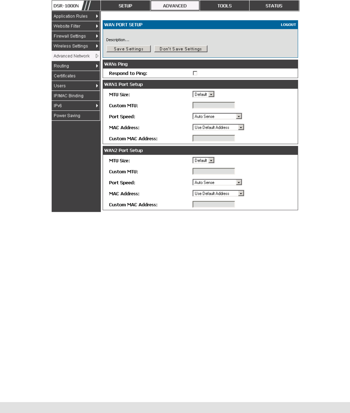
3.7 WAN Port Settings
Advanced > Advanced Network > WAN Port Setup
The physical port settings for each WAN link can be defined here. If your ISP
account defines the WAN port speed or is associated with a MAC address,
this information is required by the router to ensure a smooth connection with
the network.

D-Link DSR Series Router
48
The default MTU size supported by all ports is 1500. This is the largest
packet size that can pass through the interface without fragmentation. This
size can be increased, however large packets can introduce network lag and
bring down the interface speed. Note that a 1500 byte size packet is the
largest allowed by the Ethernet protocol at the network layer.
The port speed can be sensed by the router when Auto is selected. With this
option the optimal port settings are determined by the router and network.
The duplex (half or full) can be defined based on the port support, as well as
one of three port speeds: 10 Mbps, 100 Mbps and 1000 Mbps (i.e. 1 Gbps).
The default setting is 100 Mbps for all ports.
The default MAC address is defined during the manufacturing process for the
interfaces, and can uniquely identify this router. You can customize each
WAN port’s MAC address as needed, either by letting the WAN port assume
the current LAN host’s MAC address or by entering a MAC address manually.
User Manual
49
Figure 25: Physical WAN port settings

D-Link DSR Series Router
50
4. Wireless Access Point Setup
This router has an integrated 802.11n radio that allows you to create an access
point for wireless LAN clients. The security/encryption/authentication options are
grouped in a wireless Profile, and each configured profile will be available for
selection in the AP configuration menu. The profile defines various parameters for
the AP, including the security between the wireless client and the AP, and can be
shared between multiple APs instances on the same device when needed.
Up to four unique wireless networks can be created by configuring multiple “virtual”
APs. Each such virtual AP appears as an independent AP (unique SSID) to
supported clients in the environment, but is actually running on the same physical
radio integrated with this router.
You will need the following information to configure your wireless network:
Types of devices expected to access the wireless network and their supported
Wi-Fi™ modes
The router’s geographical region
The security settings to use for securing the wireless network.
Profiles may be thought of as a grouping of AP parameters that can then be
applied to not just one but multiple AP instances (SSIDs), thus avoiding
duplication if the same parameters are to be used on multiple AP instances
or SSIDs.
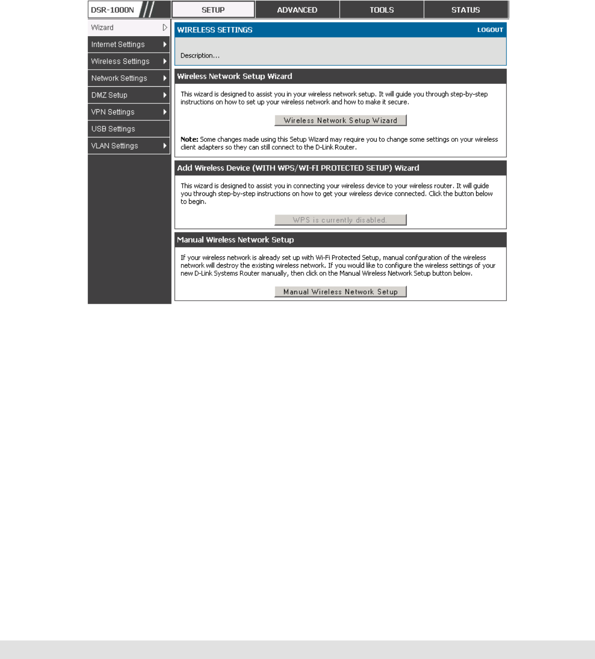
4.1 Wireless Settings Wizard
Setup > Wizard > Wireless Settings
The Wireless Network Setup Wizard is available for users new to networking.
By going through a few straightforward configuration pages you can enable a
User Manual
51
Wi-Fi™ network on your LAN and allow supported 802.11 clients to connect to
the configured Access Point.
Figure 26: Wireless Network Setup Wizards
4.1.1 Wireless Network Setup Wizard
This wizard provides a step-by-step guide to create and secure a new access
point on the router. The network name (SSID) is the AP identifier that will be
detected by supported clients. The Wizard uses a TKIP+AES cipher for WPA
/ WPA2 security; depending on support on the client side, devices associate
with this AP using either WPA or WPA2 security with the same pre-shared
key.
The wizard has the option to automatically generate a network key for the AP.
This key is the pre-shared key for WPA or WPA2 type security. Supported
clients that have been given this PSK can associate with this AP. The default
(auto-assigned) PSK is “passphrase”.

D-Link DSR Series Router
52
The last step in the Wizard is to click the Connect button, which confirms the
settings and enables this AP to broadcast its availability in the LAN.
4.1.2 Add Wireless Device with WPS
With WPS enabled on your router, the selected access point allows supported
WPS clients to join the network very easily. When the Auto option for
connecting a wireless device is chose, you will be presented with two common
WPS setup options:
Personal Identification Number (PIN): The wireless device that supports
WPS may have an alphanumeric PIN, and if entered in this field the AP will
establish a link to the client. Click Connect to complete setup and connect to
the client.
Push Button Configuration (PBC): for wireless devices that support PBC,
press and hold down on this button and within 2 minutes, click the PBC
connect button. The AP will detect the wireless device and establish a link to
the client.
You need to enable at least one AP with WPA/WPA2 security and also
enable WPS in the Advanced > Wireless Settings > WPS page to use the
WPS wizard.
4.1.3 Manual Wireless Network Setup
This button on the Wizard page will link to the Setup > Wireless Settings >
Access Points page. The manual options allow you to create new APs or
modify the parameters of APs created by the Wizard.
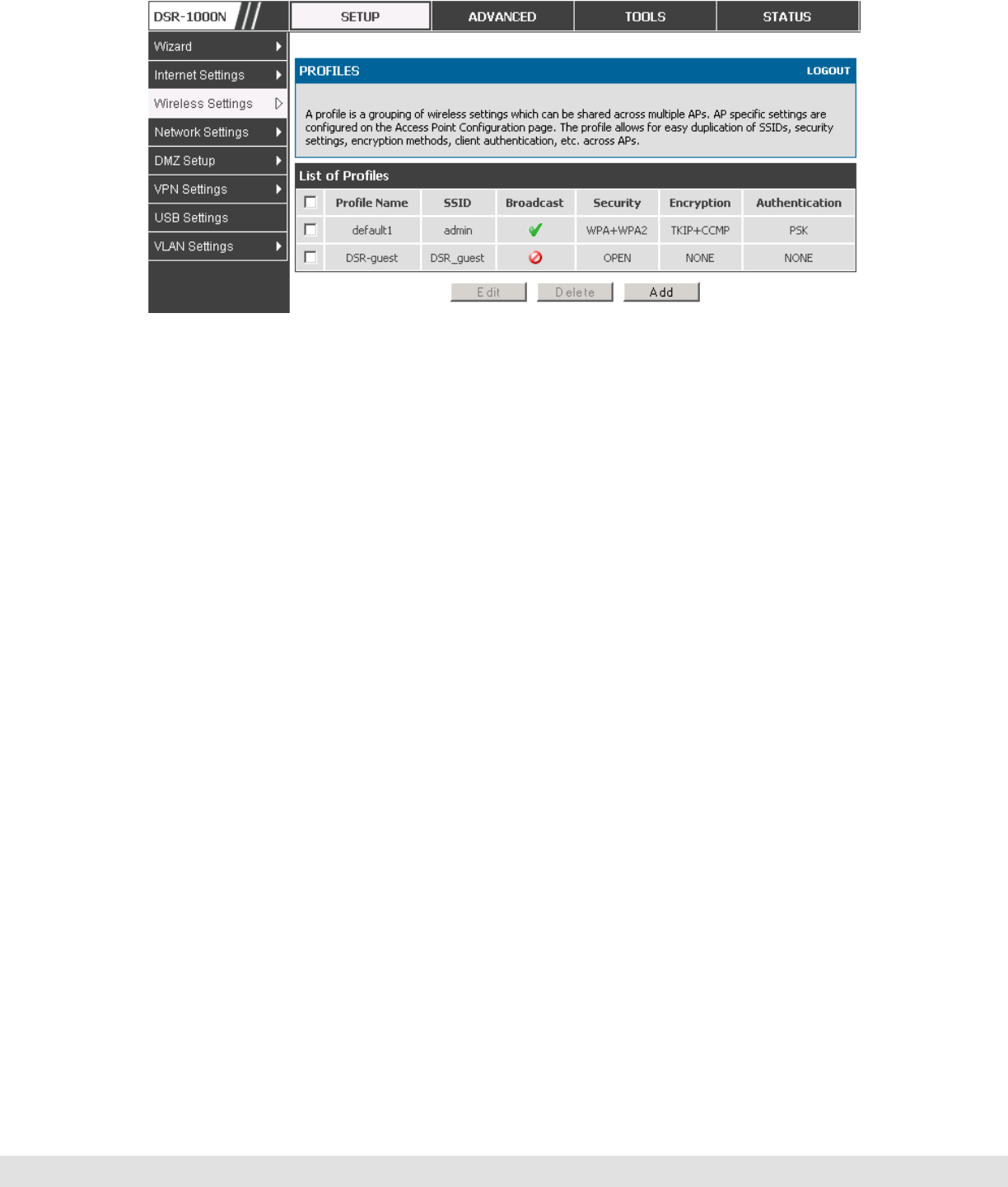
4.2 Wireless Profiles
Setup > Wireless Settings > Profiles
The profile allows you to assign the security type, encryption and
authentication to use when connecting the AP to a wireless client. The default
mode is “open”, i.e. no security. This mode is insecure as it allows any

User Manual
53
compatible wireless clients to connect to an AP configured with this security
profile.
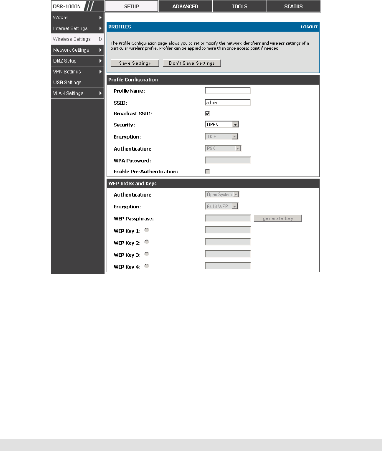
To create a new profile, use a unique profile name to identify the combination
of settings. Configure a unique SSID that will be the identifier used by the
clients to communicate to the AP using this profile. By choosing to broadcast
the SSID, compatible wireless clients within range of the AP can detect this
profile’s availability.
The AP offers all advanced 802.11 security modes, including WEP, WPA,
WPA2 and WPA+WPA2 options. The security of the Access point is
configured by the Wireless Security Type section:
Open: select this option to create a public “open” network to allow
unauthenticated devices to access this wireless gateway.
WEP (Wired Equivalent Privacy): this option requires a static (pre-shared) key
to be shared between the AP and wireless client. Note that WEP does not
support 802.11n data rates; is it appropriate for legacy 802.11 connections.
WPA (Wi-Fi Protected Access): For stronger wireless security than WEP,
choose this option. The encryption for WPA will use TKIP and also CCMP if
required. The authentication can be a pre-shared key (PSK), Enterprise mode
with RADIUS server, or both. Note that WPA does not support 802.11n data
rates; is it appropriate for legacy 802.11 connections.
WPA2: this security type uses CCMP encryption (and the option to add TKIP
encryption) on either PSK (pre-shared key) or Enterprise (RADIUS Server)
authentication.
WPA + WPA2: this uses both encryption algorithms, TKIP and CCMP. WPA
clients will use TKIP and WPA2 clients will use CCMP encryption algorithms.
“WPA+WPA2” is a security option that allows devices to connect to an AP
using the strongest security that it supports. This mode allows legacy
devices that only support WPA2 keys (such as an older wireless printer) to
connect to a secure AP where all the other wireless clients are using WPA2.
D-Link DSR Series Router
54
Figure 27: List of Available Profiles shows the variety of options available
to secure the wireless link
4.2.1 WEP Security
If WEP is the chosen security option, you must set a unique static key to be
shared with clients that wish to access this secured wireless network. This
static key can be generated from an easy-to-remember passphrase and the
selected encryption length.
Authentication: select between Open System, or Shared Key schemes
Encryption: select the encryption key size -- 64 bit WEP or 128 bit WEP. The
larger size keys provide stronger encryption, thus making the key more difficult
to crack
WEP Passphrase: enter a alphanumeric phrase and click Generate Key to
generate 4 unique WEP keys with length determined by the encryption key
size. Next choose one of the keys to be used for authentication. The selected
key must be shared with wireless clients to connect to this device.
User Manual
55
Figure 28: Profile configuration to set network security
4.2.2 WPA or WPA2 with PSK
A pre-shared key (PSK) is a known passphrase configured on the AP and
client both and is used to authenticate the wireless client. An acceptable
passphrase is between 8 to 63 characters in length.

D-Link DSR Series Router
56
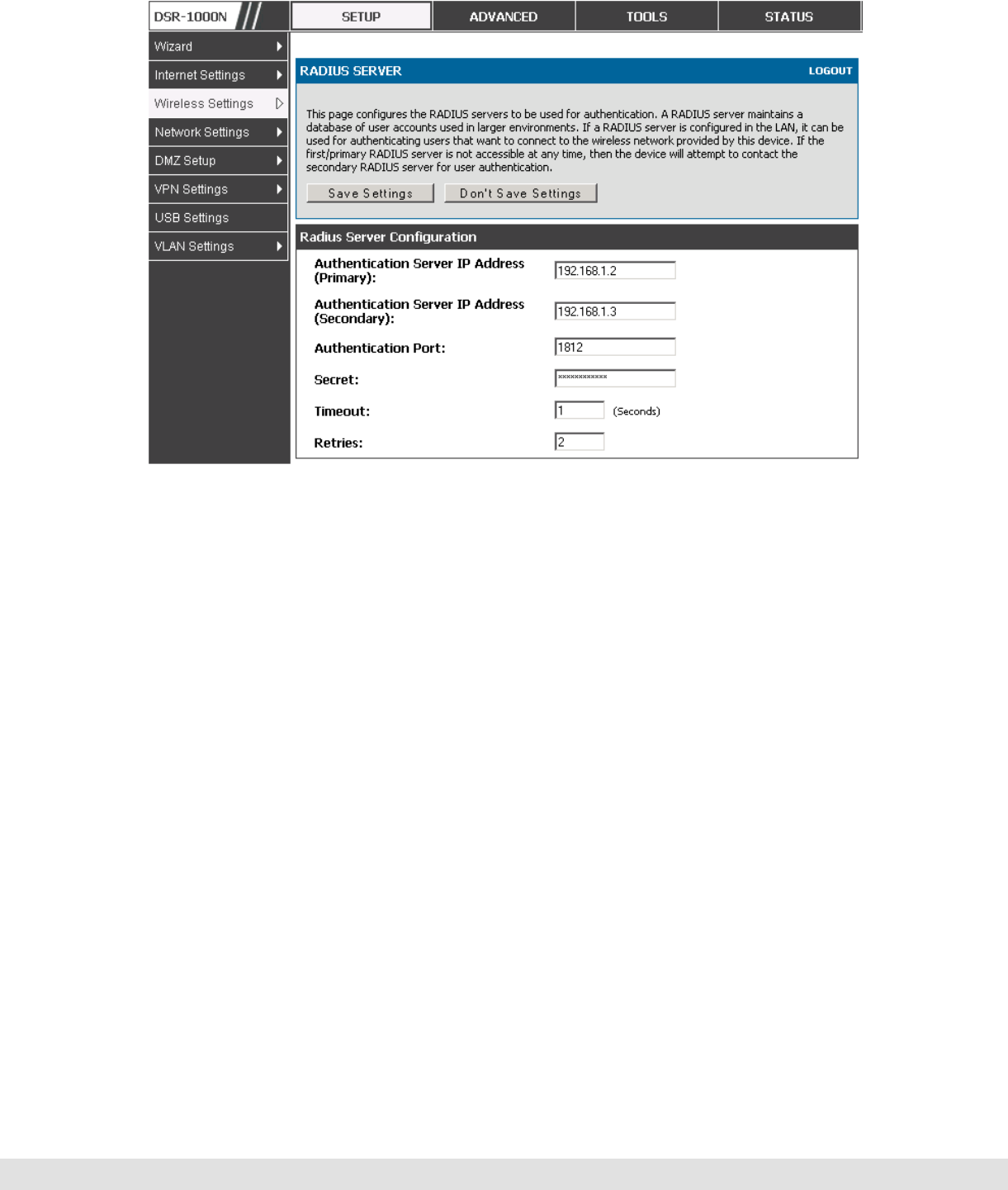
4.2.3 RADIUS Authentication
Setup > Wireless Settings > RADIUS Settings
Enterprise Mode uses a RADIUS Server for WPA and/or WPA2 security. A
RADIUS server must be configured and accessible by the router to
authenticate wireless client connections to an AP enabled with a profile that
uses RADIUS authentication.
The Authentication IP Address is required to identify the server. A secondary
RADIUS server provides redundancy in the event that the primary server
cannot be reached by the router when needed.
Authentication Port: the port for the RADIUS server connection
Secret: enter the shared secret that allows this router to log into the specified
RADIUS server(s). This key must match the shared secret on the RADIUS
Server.
The Timeout and Retries fields are used to either move to a secondary server
if the primary cannot be reached, or to give up the RADIUS authentication
attempt if communication with the server is not possible.
User Manual
57
Figure 29: RADIUS server (External Authentication) configuration
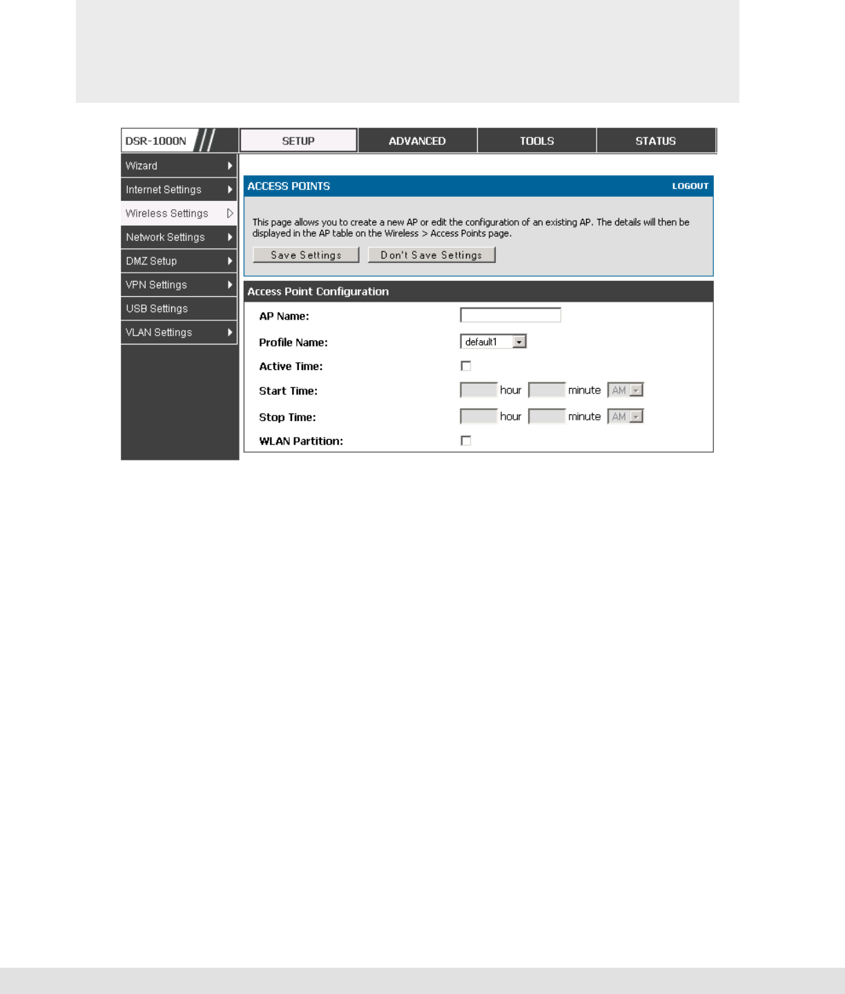
4.3 Creating and Using Access Points
Setup > Wireless Settings > Access Points
Once a profile (a group of security settings) is created, it can be assigned to
an AP on the router. The AP SSID can be configured to broadcast its
availability to the 802.11 environment can be used to establish a WLAN
network.
The AP configuration page allows you to create a new AP and link to it one of
the available profiles. This router supports multiple AP’s referred to as virtual
access points (VAPs). Each virtual AP that has a unique SSIDs appears as an
independent access point to clients. This valuable feature allows the router’s
radio to be configured in a way to optimize security and throughput for a
group of clients as required by the user. To create a VAP, click the “add”
button on the Setup > Wireless Settings > Access Points page. After
setting the AP name, the profile dropdown menu is used to select one of the
configured profiles.
D-Link DSR Series Router
58
The AP Name is a unique identifier used to manage the AP from the GUI,
and is not the SSID that is detected by clients when the AP has broadcast
enabled.
Figure 30: Virtual AP configuration
A valuable power saving feature is the start and stop time control for this AP.
You can conserve on the radio power by disabling the AP when it is not in
use. For example on evenings and weekends if you know there are no
wireless clients, the start and stop time will enable/disable the access point
automatically.
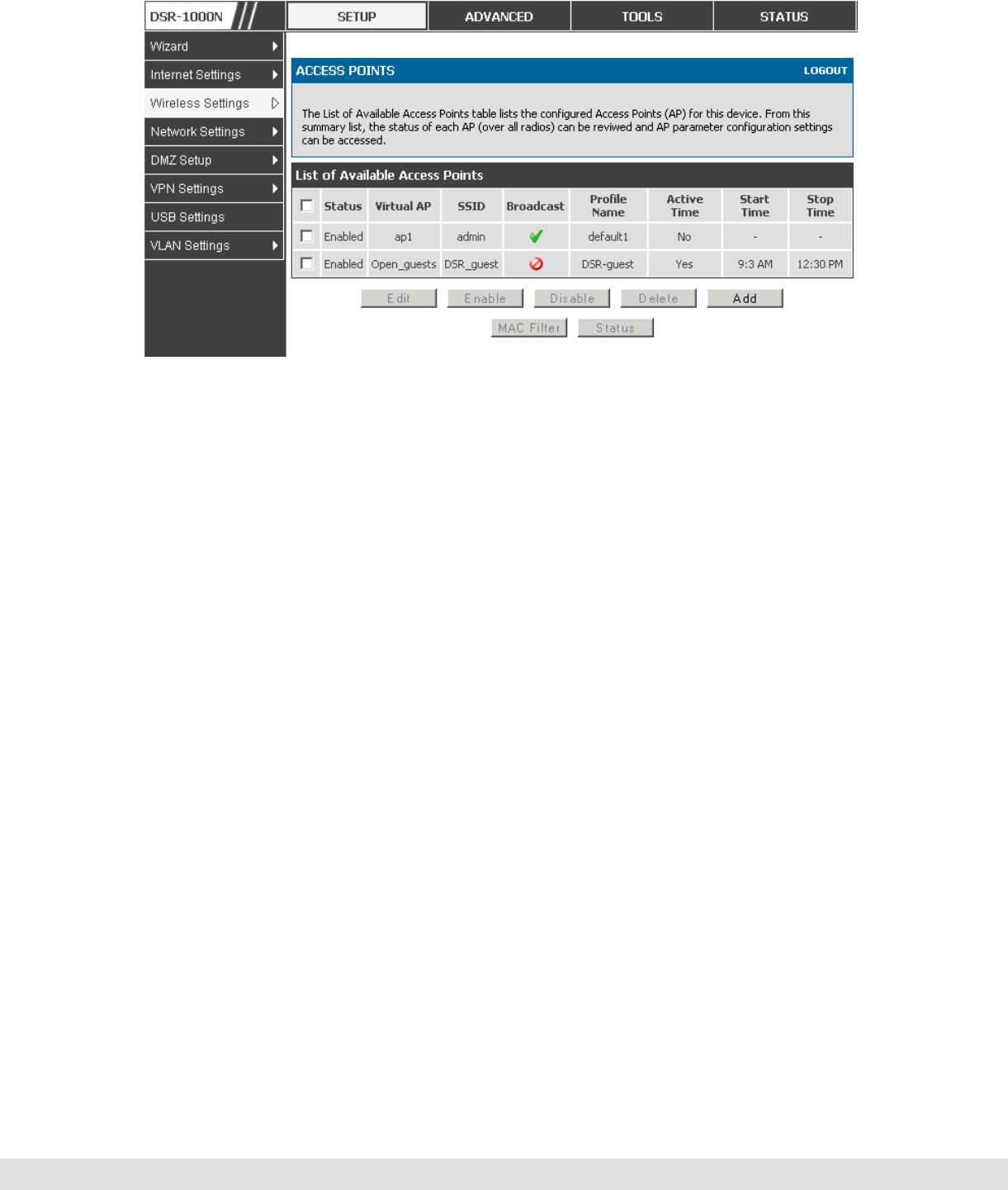
Once the AP settings are configured, you must enable the AP on the radio on
the Setup > Wireless Settings > Access Points page. The status field
changes to “Enabled” if the AP is available to accept wireless clients. If the
AP is configured to broadcast its SSID (a profile parameter), a green check
mark indicating it is broadcasting will be shown in the List of Available Access
points.
User Manual
59
Figure 31: List of configured access points (Virtual APs) shows one enabled
access point on the radio, broadcasting its SSID
The clients connected to a particular AP can be viewed by using the Status
Button on the List of Available Access Points. Traffic statistics are shown for
that individual AP, as compared to the summary stats for each AP on the
Statistics table. Connected clients are sorted by the MAC address and
indicate the security parameters used by the wireless link, as well as the time
connected to this particular AP. Clicking the Details button next to the
connected client will give the detailed send and receive traffic statistics for the
wireless link between this AP and the client.
4.3.1 Primary benefits of Virtual APs:
Optimize throughput: if 802.11b, 802.11 g, and 802.11n clients are expected
to access the LAN via this router, creating 3 VAPs will allow you to manage or
shape traffic for each group of clients. A unique SSID can be created for the
network of 802.11b clients and another SSID can be assigned for the 802.11n
clients. Each can have different security parameters – remember, the SSID
and security of the link is determined by the profile. In this way legacy clients
can access the network without bringing down the overall throughput of more
capable 802.11n clients.

D-Link DSR Series Router
60
Optimize security: you may wish to support select legacy clients that only
offer WEP security while using WPA2 security for the majority of clients for
the radio. By creating two VAPs configured with different SSIDs and different
security parameters, both types of clients can connect to the LAN. Since
WPA2 is more secure, you may want to broadcast this SSID and not
broadcast the SSID for the VAP with WEP since it is meant to be used for a
few legacy devices in this scenario.
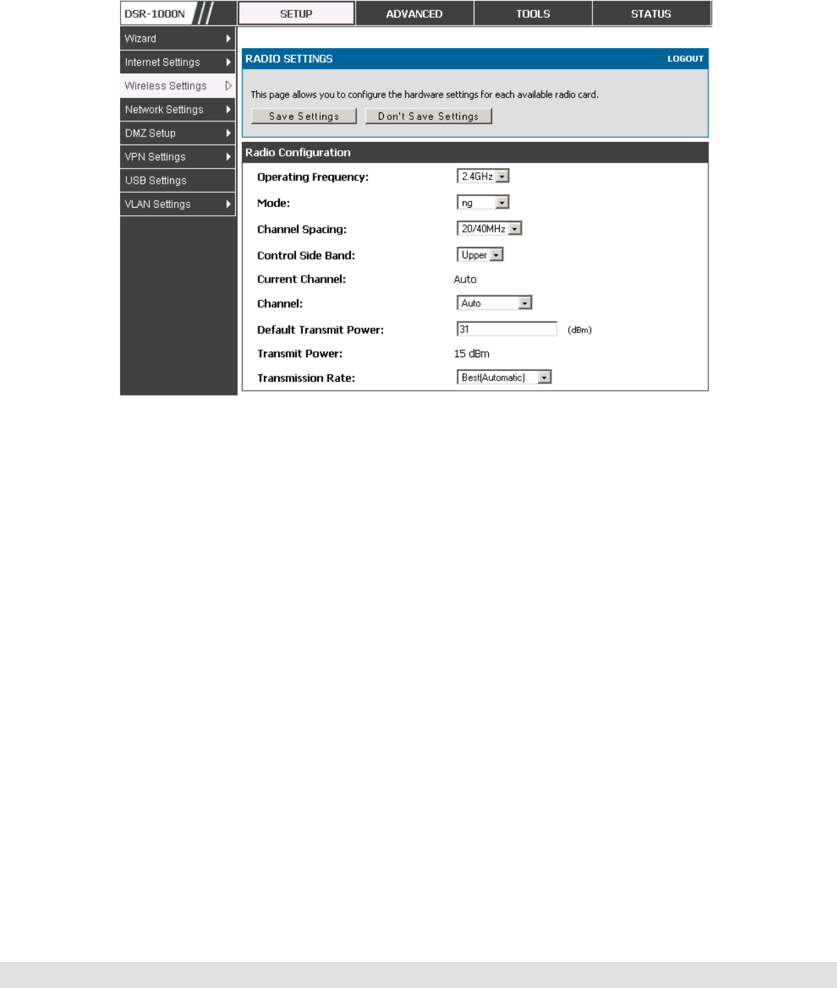
4.4 Tuning Radio Specific Settings
Setup > Wireless Settings > Radio Settings
The Radio Settings page lets you configure the channels and power levels
available for the AP’s enabled on the device. The router has a dual band
802.11n radio, meaning either 2.4 GHz or 5 GHz frequency of operation can
be selected (not concurrently though). Based on the selected operating
frequency, the mode selection will let you define whether legacy connections
or only 802.11n connections (or both) are accepted on configured APs.
User Manual
61
Figure 32: Radio card configuration options
The ratified 802.11n support on this radio requires selecting the appropriate
broadcast (NA or NG etc.) mode, and then defining the channel spacing and
control side band for 802.11n traffic. The default settings are appropriate for
most networks. For example, changing the channel spacing to 40 MHz can
improve bandwidth at the expense of supporting earlier 802.11n clients.
The available transmission channels are governed by regulatory constraints
based on the region setting of the router. The maximum transmission power
is similarly governed by regulatory limits; you have the option to decrease
from the default maximum to reduce the signal strength of traffic out of the
radio.
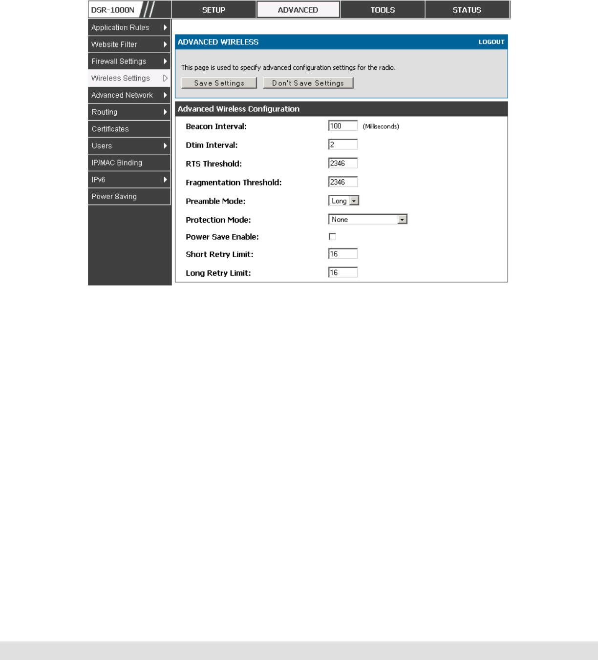
4.5 Advanced Wireless Settings
Advanced > Wireless Settings > Advanced Wireless
Sophisticated wireless administrators can modify the 802.11 communication
parameters in this page. Generally, the default settings are appropriate for
D-Link DSR Series Router
62
most networks. Please refer to the GUI integrated help text for further details
on the use of each configuration parameter.
Figure 33: Advanced Wireless communication settings
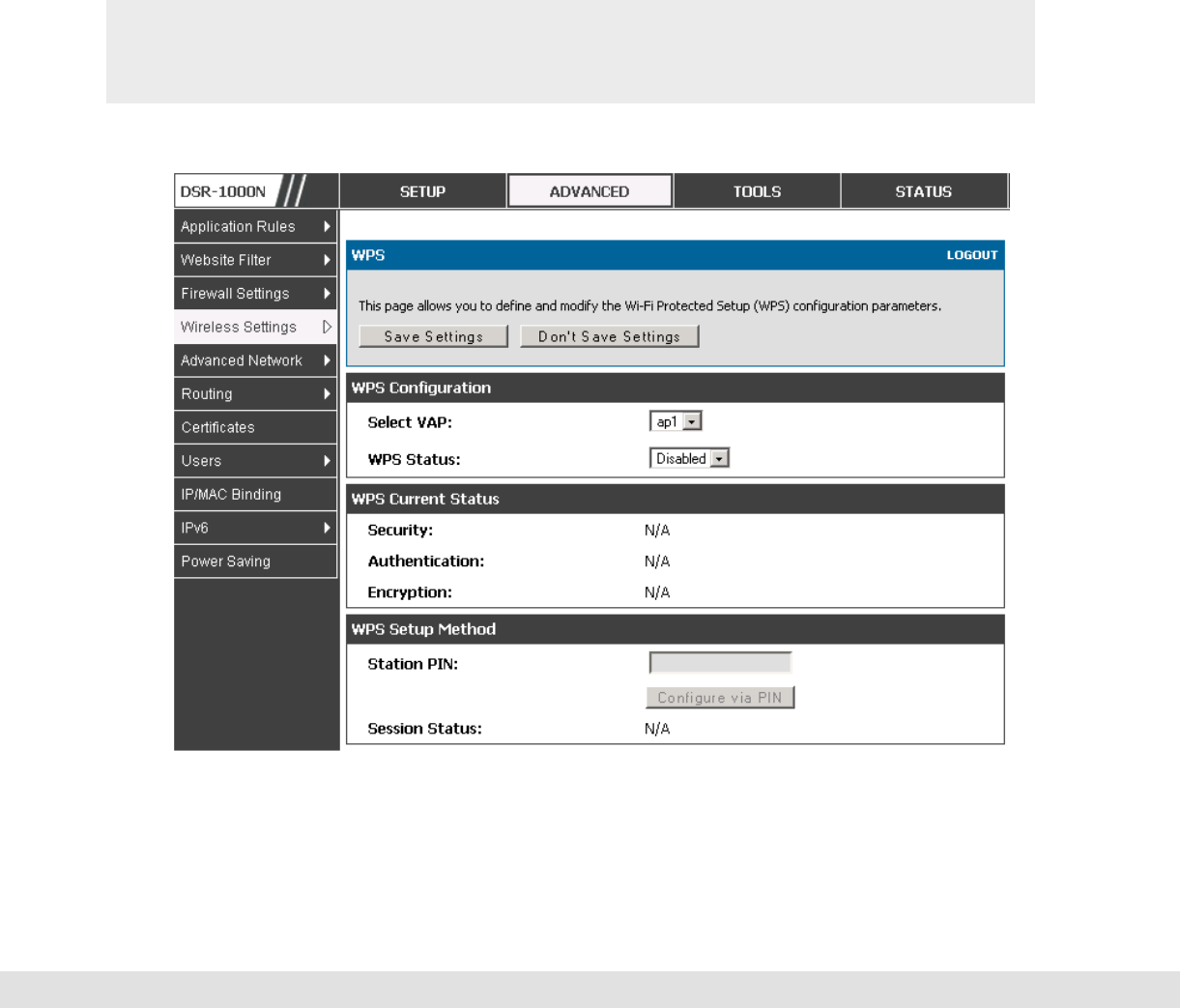
4.6 Wi-Fi Protected Setup (WPS)
Advanced > Wireless Settings > WPS
WPS is a simplified method to add supporting wireless clients to the network.
WPS is only applicable for APs that employ WPA or WPA2 security. To use
WPS, select the eligible VAPs from the dropdown list of APs that have been
configured with this security and enable WPS status for this AP.
The WPS Current Status section outlines the security, authentication, and
encryption settings of the selected AP. These are consistent with the AP’s
profile. There are two setup options available for WPS:
User Manual
63
Personal Identification Number (PIN): The wireless device that supports
WPS may have an alphanumeric PIN, if so add the PIN in this field. The
router will connect within 60 seconds of clicking the “Configure via PIN” button
immediately below the PIN field. There is no LED indication that a client has
connected.
Push Button Configuration (PBC): for wireless devices that support PBC,
press and hold down on this button and within 2 minutes click the PBC
connect button. The AP will detect the wireless device and establish a link to
the client.
More than one AP can use WPS, but only one AP can be used to establish
WPS links to client at any given time.

D-Link DSR Series Router
64
Figure 34: WPS configuration for an AP with WPA/WPA2 profile

65
5. Securing the Private Network
You can secure your network by creating and applying rules that your router uses
to selectively block and allow inbound and outbound Internet traffic. You then
specify how and to whom the rules apply. To do so, you must define the following:
Services or traffic types (examples: web browsing, VoIP, other standard
services and also custom services that you define)
Direction for the traffic by specifying the source and destination of traffic; this is
done by specifying the “From Zone” (LAN/WAN/DMZ) and “To Zone”
(LAN/WAN/DMZ)
Schedules as to when the router should apply rules
Any Keywords (in a domain name or on a URL of a web page) that the router
should allow or block
Rules for allowing or blocking inbound and outbound Internet traffic for
specified services on specified schedules
MAC addresses of devices that should not access the internet
Port triggers that signal the router to allow or block access to specified services
as defined by port number
Reports and alerts that you want the router to send to you
You can, for example, establish restricted-access policies based on time-of-day,
web addresses, and web address keywords. You can block Internet access by
applications and services on the LAN, such as chat rooms or games. You can
block just certain groups of PCs on your network from being accessed by the WAN
or public DMZ network.
5.1 Firewall Rules
Advanced > Firewall Settings > Firewall Rules
Inbound (WAN to LAN/DMZ) rules restrict access to traffic entering your network,
selectively allowing only specific outside users to access specific local resources.

D-Link DSR Series Router
66
By default all access from the insecure WAN side are blocked from accessing the
secure LAN, except in response to requests from the LAN or DMZ. To allow
outside devices to access services on the secure LAN, you must create an inbound
firewall rule for each service.
If you want to allow incoming traffic, you must make the router’s WAN port IP
address known to the public. This is called “exposing your host.” How you make
your address known depends on how the WAN ports are configured; for this router
you may use the IP address if a static address is assigned to the WAN port, or if
your WAN address is dynamic a DDNS (Dynamic DNS) name can be used.
Outbound (LAN/DMZ to WAN) rules restrict access to traffic leaving your network,
selectively allowing only specific local users to access specific outside resources.
The default outbound rule is to allow access from the secure zone (LAN) to either
the public DMZ or insecure WAN. You can change this default behavior in the
Firewall Settings > Default Outbound Policy page. When the default outbound
policy is allow always, you can to block hosts on the LAN from accessing internet
services by creating an outbound firewall rule for each service.
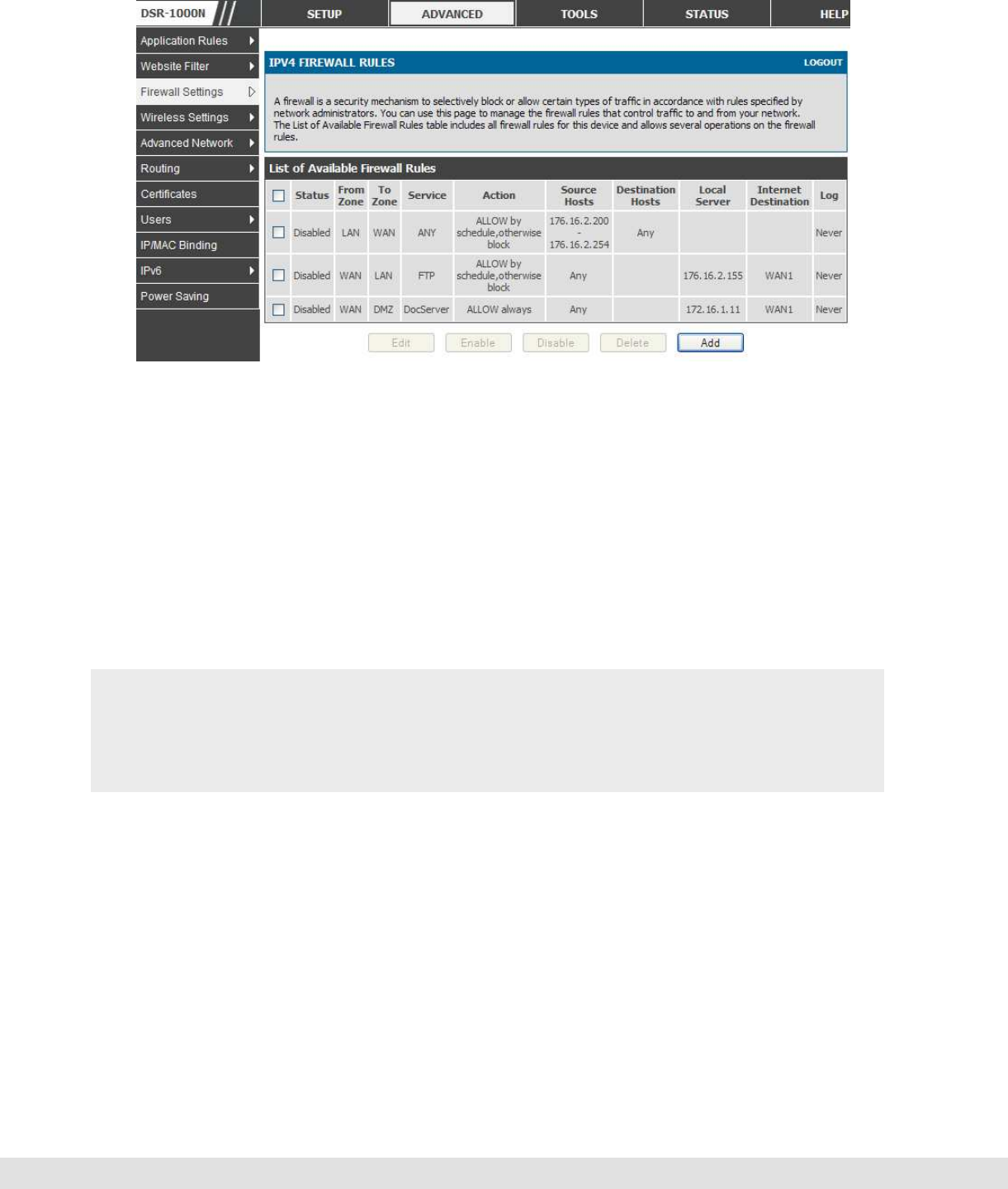
User Manual
67
Figure 35: List of Available Firewall Rules
5.2 Defining Rule Schedules
Tools > Schedules
Firewall rules can be enabled or disabled automatically if they are associated
with a configured schedule. The schedule configuration page allows you to
define days of the week and the time of day for a new schedule, and then this
schedule can be selected in the firewall rule configuration page.
All schedules will follow the time in the routers configured time zone. Refer
to the section on choosing your Time Zone and configuring NTP servers for
more information.
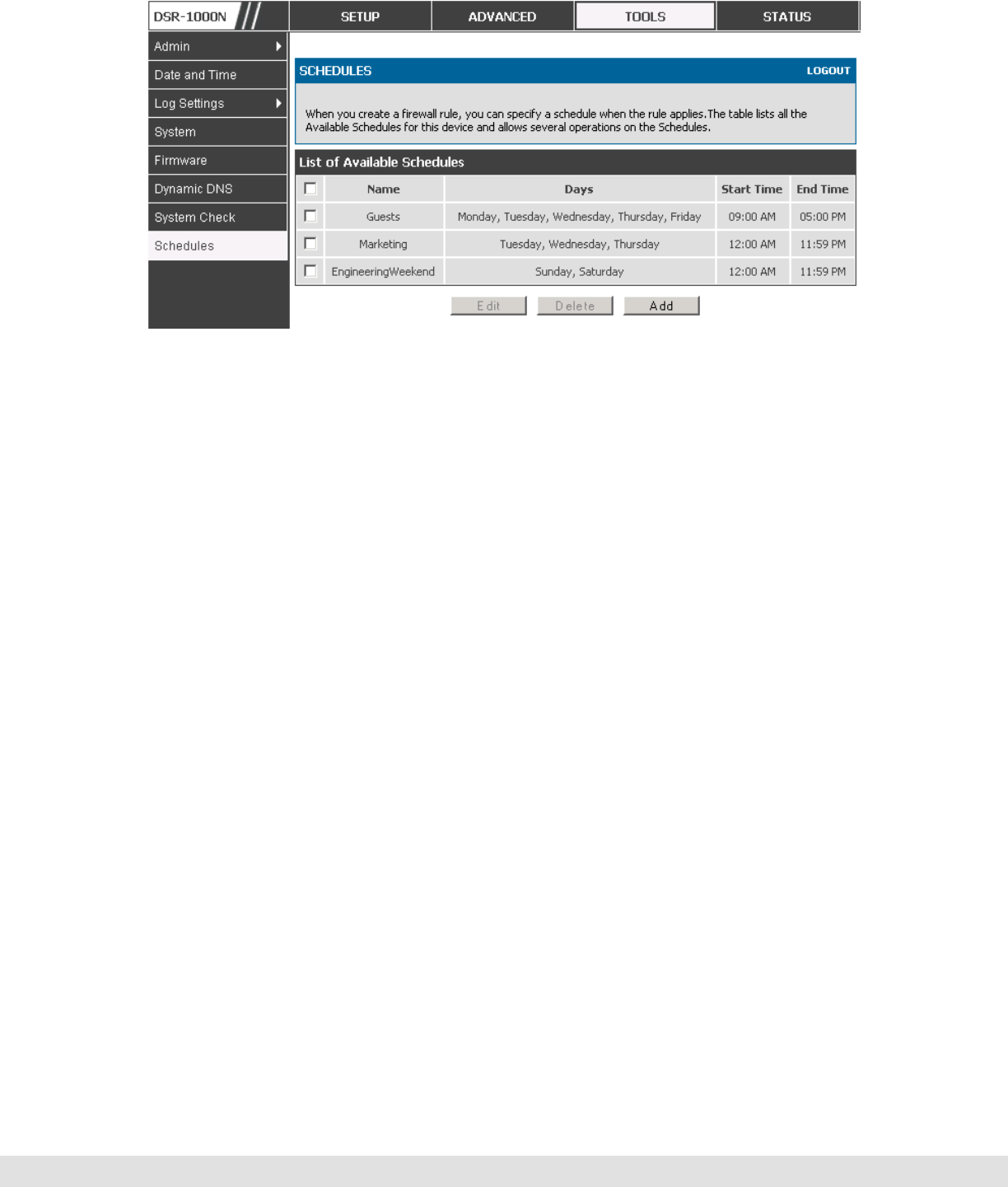
D-Link DSR Series Router
68
Figure 36: List of Available Schedules to bind to a firewall rule
5.3 Configuring Firewall Rules
Advanced > Firewall Settings > Firewall Rules
All configured firewall rules on the router are displayed in the Firewall Rules
list. This list also indicates whether the rule is enabled (active) or not, and
gives a summary of the From/To zone as well as the services or users that
the rule affects.
To create a new firewall rules, follow the steps below:
1. View the existing rules in the List of Available Firewall Rules table.
2. To edit or add an outbound or inbound services rule, do the following:
To edit a rule, click the checkbox next to the rule and click Edit to reach that
rule’s configuration page.
To add a new rule, click Add to be taken to a new rule’s configuration page.
Once created, the new rule is automatically added to the original table.
3. Chose the From Zone to be the source of originating traffic: either the secure
LAN, public DMZ, or insecure WAN. For an inbound rule WAN should be
selected as the From Zone.

User Manual
69
4. Choose the To Zone to be the destination of traffic covered by this rule. If the
From Zone is the WAN, the To Zone can be the public DMZ or secure LAN.
Similarly if the From Zone is the LAN, then the To Zone can be the public DMZ or
insecure WAN.
5. Parameters that define the firewall rule include the following:
• Service: ANY means all traffic is affected by this rule. For a specific
service the drop down list has common services, or you can select a
custom defined service.
• Action & Schedule: Select one of the 4 actions that this rule defines:
BLOCK always, ALLOW always, BLOCK by schedule otherwise ALLOW,
or ALLOW by schedule otherwise BLOCK. A schedule must be
preconfigured in order for it to be available in the dropdown list to assign
to this rule.
Source & Destination users: For each relevant category, select the users to
which the rule applies:
• Any (all users)
• Single Address (enter an IP address)
• Address Range (enter the appropriate IP address range)
Log: traffic that is filtered by this rule can be logged; this requires configuring
the router’s logging feature separately.
QoS Priority: Outbound rules (where To Zone = insecure WAN only) can have
the traffic marked with a QoS priority tag. Select a priority level:
• Normal-Service: ToS=0 (lowest QoS)
• Minimize-Cost: ToS=1
• Maximize-Reliability: ToS=2
• Maximize-Throughput: ToS=4

D-Link DSR Series Router
70
Minimize-Delay: ToS=8 (highest QoS)
6. Inbound rules can use Destination NAT (DNAT) for managing traffic from the
WAN. Destination NAT is available when the To Zone = DMZ or secure LAN.
With an inbound allow rule you can enter the internal server address that is
hosting the selected service.
You can enable port forwarding for an incoming service specific rule (From
Zone = WAN) by selecting the appropriate checkbox. This will allow the
selected service traffic from the internet to reach the appropriate LAN port via
a port forwarding rule.
Translate Port Number: With port forwarding, the incoming traffic to be
forwarded to the port number entered here.
External IP address: The rule can be bound to a specific WAN interface by
selecting either the primary WAN or configurable port WAN as the source IP
address for incoming traffic.
This router supports multi-NAT and so the External IP address does not
necessarily have to be the WAN address. On a single WAN interface,
multiple public IP addresses are supported. If your ISP assigns you more
than one public IP address, one of these can be used as your primary IP
address on the WAN port, and the others can be assigned to servers on the
LAN or DMZ. In this way the LAN/DMZ server can be accessed from the
internet by its aliased public IP address.
7. Outbound rules can use Source NAT (SNAT) in order to statically map (bind) all
LAN/DMZ traffic matching the rule parameters to a specific WAN interface or
external IP address (usually provided by your ISP).

User Manual
71
Once the new or modified rule parameters are saved, it appears in the master list of
firewall rules. To enable or disable a rule, click the checkbox next to the rule in the
list of firewall rules and choose Enable or Disable.
The router applies firewall rules in the order listed. As a general rule, you
should move the strictest rules (those with the most specific services or
addresses) to the top of the list. To reorder rules, click the checkbox next to
a rule and click up or down.
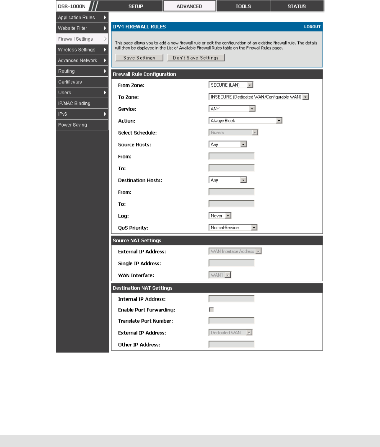
D-Link DSR Series Router
72
Figure 37: The firewall rule configuration page allows you to define the
To/From zone, service, action, schedules, and specify source/destination IP
addresses as needed.

User Manual
73
5.3.1 Firewall Rule Configuration Examples
Example 1: Allow inbound HTTP traffic to the DMZ
Situation: You host a public web server on your local DMZ network. You
want to allow inbound HTTP requests from any outside IP address to the IP
address of your web server at any time of day.
Solution: Create an inbound rule as follows.
Parameter Value
From Zone Insecure (WAN1/WAN2)
To Zone Public (DMZ)
Service HTTP
Action ALLOW always
Send to Local Server
(DNAT IP) 192.168.5.2 (web server IP address)
Destination Users Any
Log Never
Example 2: Allow videoconferencing from range of outside IP addresses
Situation: You want to allow incoming videoconferencing to be initiated from
a restricted range of outside IP addresses (132.177.88.2 - 132.177.88.254),
from a branch office.
Solution: Create an inbound rule as follows. In the example, CUSeeMe (the
video conference service used) connections are allowed only from a
specified range of external IP addresses.

D-Link DSR Series Router
74
Parameter Value
From Zone Insecure (WAN1/WAN2)
To Zone Secure (LAN)
Service CU-SEEME:UDP
Action ALLOW always
Send to Local Server
(DNAT IP) 192.168.10.11
Destination Users Address Range
From 132.177.88.2
To 134.177.88.254
Enable Port Forwarding Yes (enabled)
Example 3: Multi-NAT configuration
Situation: You want to configure multi-NAT to support multiple public IP
addresses on one WAN port interface.
Solution: Create an inbound rule that configures the firewall to host an
additional public IP address. Associate this address with a web server on the
DMZ. If you arrange with your ISP to have more than one public IP address
for your use, you can use the additional public IP addresses to map to
servers on your LAN. One of these public IP addresses is used as the
primary IP address of the router. This address is used to provide Internet
access to your LAN PCs through NAT. The other addresses are available to
map to your DMZ servers.
The following addressing scheme is used to illustrate this procedure:
Router
WAN IP address: 10.1.0.118

User Manual
75
LAN IP address: 192.168.10.1; subnet 255.255.255.0
Web server host in the DMZ, IP address: 192.168.12.222
Access to Web server: (simulated) public IP address 10.1.0.52
Example 4: Block traffic by schedule if generated from specific range of
machines
Use Case: Block all HTTP traffic on the weekends if the request originates
from a specific group of machines in the LAN having a known range of IP
addresses, and anyone coming in through the Network from the WAN (i.e. all
remote users).
Configuration:
1. Setup a schedule:
To setup a schedule that affects traffic on weekends only, navigate to Security:
Schedule, and name the schedule “Weekend”
Parameter Value
From Zone Insecure (WAN1/WAN2)
To Zone Public (DMZ)
Service HTTP
Action ALLOW always
Send to Local Server (DNAT IP) 192.168.12.222 ( web server local IP address)
Destination Users Single Address
From 10.1.0.52
WAN Users Any
Log Never

D-Link DSR Series Router
76
Define “weekend” to mean 12 am Saturday morning to 12 am Monday morning
– all day Saturday & Sunday
In the Scheduled days box, check that you want the schedule to be active for
“specific days”. Select “Saturday” and “Sunday”
In the scheduled time of day, select “all day” – this will apply the schedule
between 12 am to 11:59 pm of the selected day.
Click apply – now schedule “Weekend” isolates all day Saturday and Sunday
from the rest of the week.
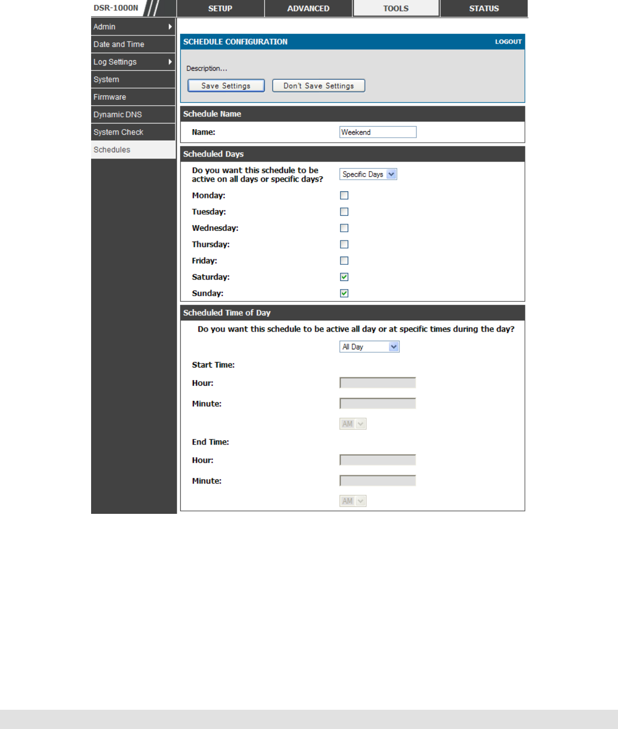
User Manual
77
Figure 38: Schedule configuration for the above example.
2. Since we are trying to block HTTP requests, it is a service with To Zone: Insecure
(WAN1/WAN2) that is to be blocked according to schedule “Weekend”.

D-Link DSR Series Router
78
3. Select the Action to “Block by Schedule, otherwise allow”. This will take a
predefined schedule and make sure the rule is a blocking rule during the defined
dates/times. All other times outside the schedule will not be affected by this
firewall blocking rule
4. As we defined our schedule in schedule “Weekend”, this is available in the
dropdown menu
5. We want to block the IP range assigned to the marketing group. Let’s say they
have IP 192.168.10.20 to 192.168.10.30. On the Source Users dropdown, select
Address Range and add this IP range as the From and To IP addresses.
6. We want to block all HTTP traffic to any services going to the insecure zone. The
Destination Users dropdown should be “any”.
7. We don’t need to change default QoS priority or Logging (unless desired) –
clicking apply will add this firewall rule to the list of firewall rules.
8. The last step is to enable this firewall rule. Select the rule, and click “enable”
below the list to make sure the firewall rule is active
5.4 Security on Custom Services
Advanced > Firewall Settings > Custom Services
Custom services can be defined to add to the list of services available during
firewall rule configuration. While common services have known
TCP/UDP/ICMP ports for traffic, many custom or uncommon applications
exist in the LAN or WAN. In the custom service configuration menu you can
define a range of ports and identify the traffic type (TCP/UDP/ICMP) for this
service. Once defined, the new service will appear in the services list of the
firewall rules configuration menu.
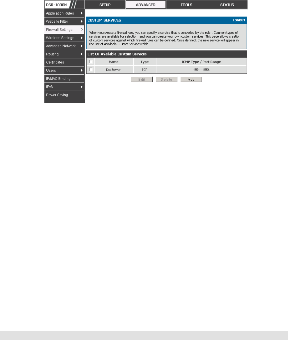
User Manual
79
Figure 39: Schedule configuration for the above example.
5.5 ALG support
Advanced > Firewall Settings > ALGs
Application Level Gateways (ALGs) are security component that enhance the
firewall and NAT support of this router to seamlessly support application layer
protocols. In some cases enabling the ALG will allow the firewall to use
dynamic ephemeral TCP/ UDP ports to communicate with the known ports a
particular client application (such as H.323 or RTSP) requires, without which
the admin would have to open large number of ports to accomplish the same
support. Because the ALG understands the protocol used by the specific
application that it supports, it is a very secure and efficient way of introducing
support for client applications through the router’s firewall.
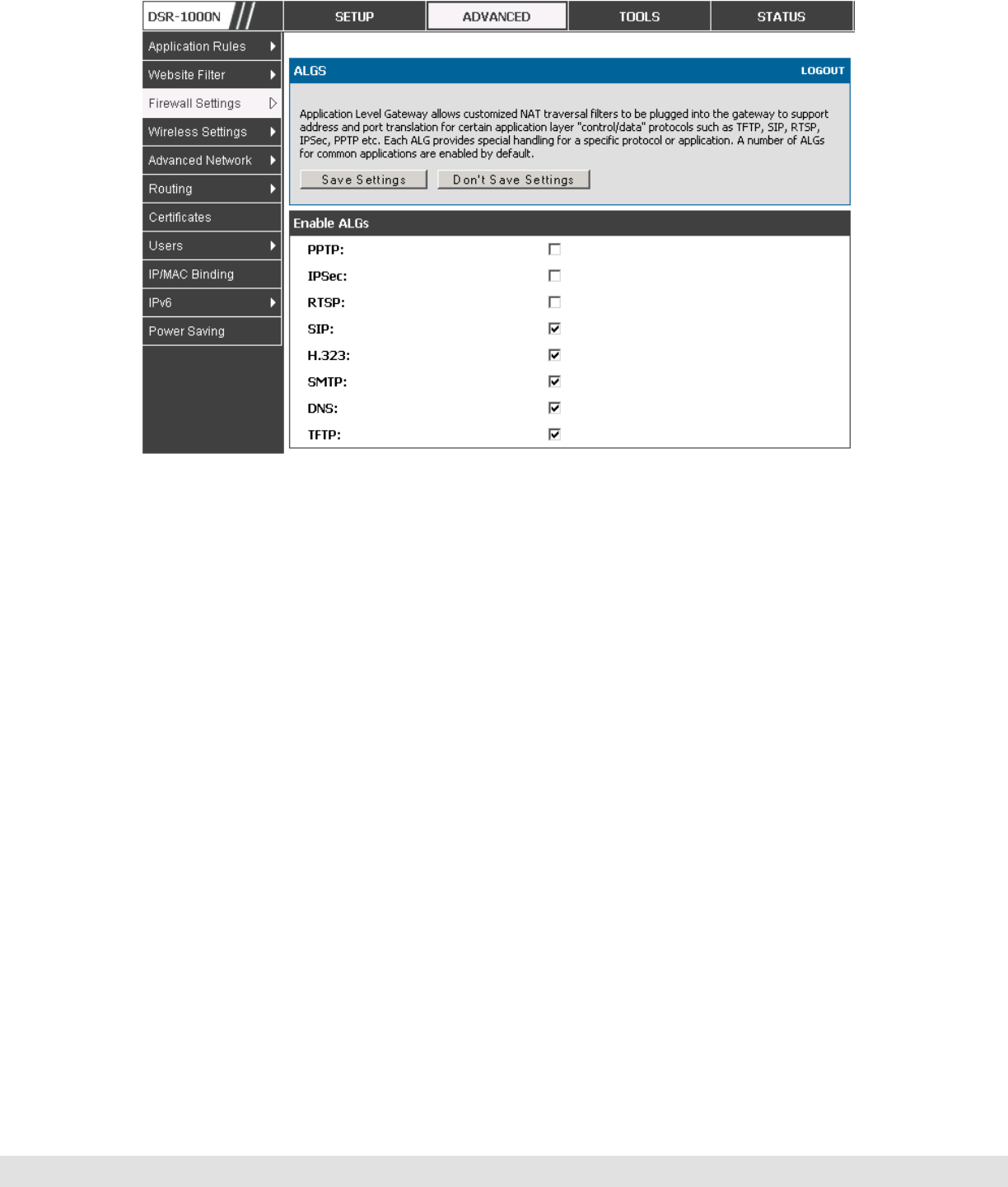
D-Link DSR Series Router
80
Figure 40: Available ALG support on the router.
5.6 VPN Passthrough for Firewall
Advanced > Firewall Settings > VPN Passthrough
This router’s firewall settings can be configured to allow encrypted VPN traffic
for IPsec, PPTP, and L2TP VPN tunnel connections between the LAN and
internet. A specific firewall rule or service is not appropriate to introduce this
passthrough support; instead the appropriate check boxes in the VPN
Passthrough page must be enabled.
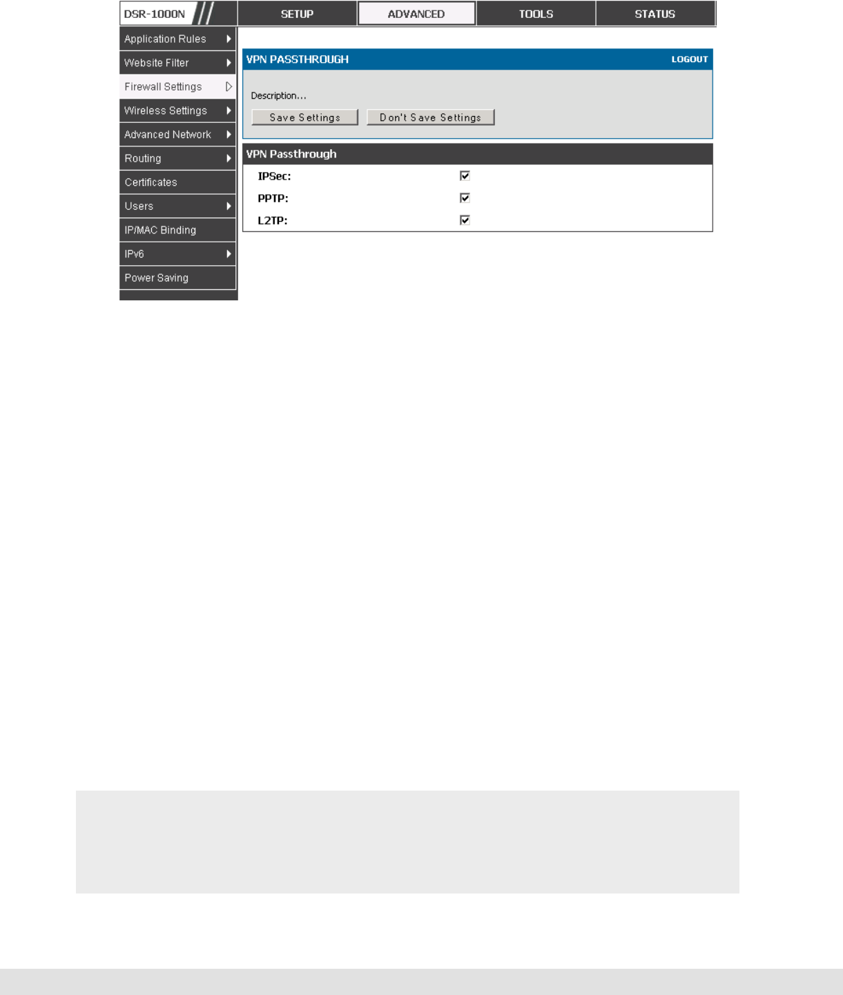
User Manual
81
Figure 41: Passthrough options for VPN tunnels
5.7 Application Rules
Advanced > Application Rules > Application Rules
Application rules are also referred to as port triggering. This feature allows
devices on the LAN or DMZ to request one or more ports to be forwarded to
them. Port triggering waits for an outbound request form the LAN/DMZ on
one of the defined outgoing ports, and then opens an incoming port for that
specified type of traffic. This can be thought of as a form of dynamic port
forwarding while an application is transmitting data over the opened outgoing
or incoming port(s).
Port triggering application rules are more flexible than static port forwarding
that is an available option when configuring firewall rules. This is because a
port triggering rule does not have to reference a specific LAN IP or IP range.
As well ports are not left open when not in use, thereby providing a level of
security that port forwarding does not offer.
Port triggering is not appropriate for servers on the LAN, since there is a
dependency on the LAN device making an outgoing connection before
incoming ports are opened.

D-Link DSR Series Router
82
Some applications require that when external devices connect to them, they
receive data on a specific port or range of ports in order to function properly.
The router must send all incoming data for that application only on the
required port or range of ports. The router has a list of common applications
and games with corresponding outbound and inbound ports to open. You can
also specify a port triggering rule by defining the type of traffic (TCP or UDP)
and the range of incoming and outgoing ports to open when enabled.
Figure 42: List of Available Application Rules showing 4 unique rules
The application rule status page will list any active rules, i.e. incoming ports
that are being triggered based on outbound requests from a defined outgoing
port.
5.8 Web Content Filtering
The gateway offers some standard web filtering options to allow the admin to
easily create internet access policies between the secure LAN and insecure
WAN. Instead of creating policies based on the type of traffic (as is the case
when using firewall rules), web based content itself can be used to determine
if traffic is allowed or dropped.
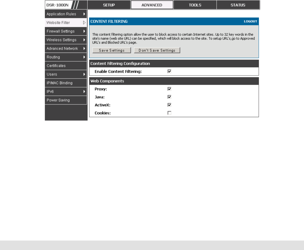
User Manual
83
Content Filtering
Advanced > Website Filter > Content Filtering
Content filtering must be enabled to configure and use the subsequent
features (list of Trusted Domains, filtering on Blocked Keywords, etc.). Proxy
servers, which can be used to circumvent certain firewall rules and thus a
potential security gap, can be blocked for all LAN devices. Java applets can
be prevented from being downloaded from internet sites, and similarly the
gateway can prevent ActiveX controls from being downloaded via Internet
Explorer. For added security cookies, which typically contain session
information, can be blocked as well for all devices on the private network.
Figure 43: Content Filtering used to block access to proxy servers and
prevent ActiveX controls from being downloaded
Approved URLs
Advanced > Website Filter > Approved URLs
The Approved URLs is an acceptance list for all URL domain names.
Domains added to this list are allowed in any form. For example, if the
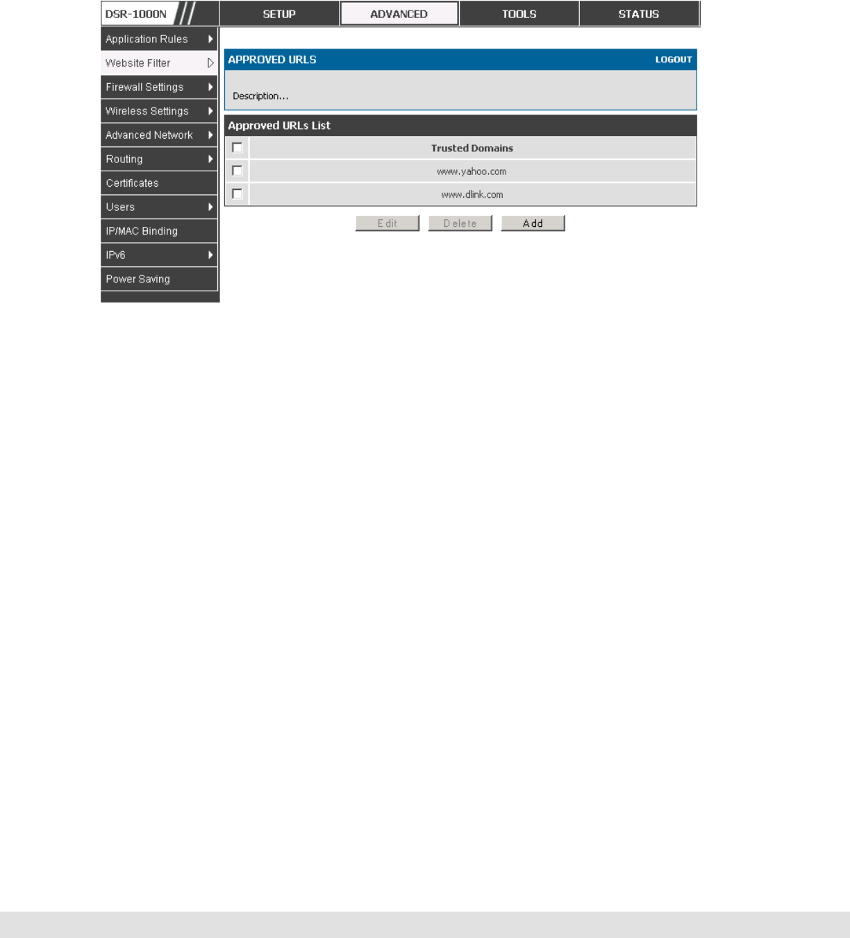
D-Link DSR Series Router
84
domain “yahoo” is added to this list then all of the following URL’s are
permitted access from the LAN: www.yahoo.com, yahoo.co.uk, etc.
Figure 44: Two trusted domains added to the Approved URLs List
Blocked Keywords
Advanced > Website Filter > Blocked URLs
Keyword blocking allows you to block all website URL’s or site content that
contains the keywords in the configured list. This is lower priority than the
Approved URL List; i.e. if the blocked keyword is present in a site allowed by
a Trusted Domain in the Approved URL List, then access to that site will be
allowed.
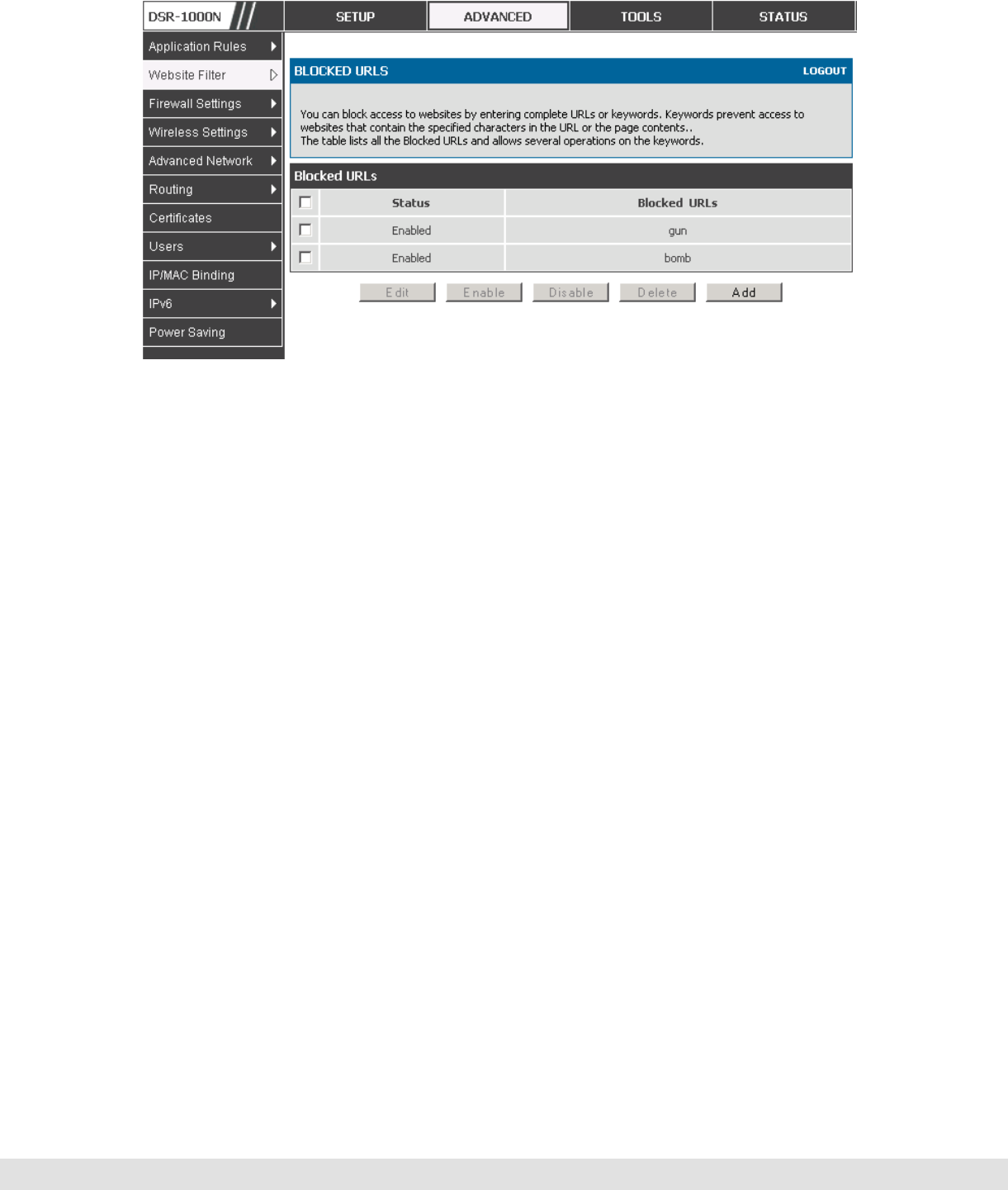
User Manual
85
Figure 45: Two keywords added to the block list
5.9 IP/MAC Binding
Advanced > IP/MAC Binding
Another available security measure is to only allow outbound traffic (from the
LAN to WAN) when the LAN node has an IP address matching the MAC
address bound to it. This is IP/MAC Binding, and by enforcing the gateway to
validate the source traffic’s IP address with the unique MAC Address of the
configured LAN node, the administrator can ensure traffic from that IP
address is not spoofed. In the event of a violation (i.e. the traffic’s source IP
address doesn’t match up with the expected MAC address having the same IP
address) the packets will be dropped and can be logged for diagnosis.
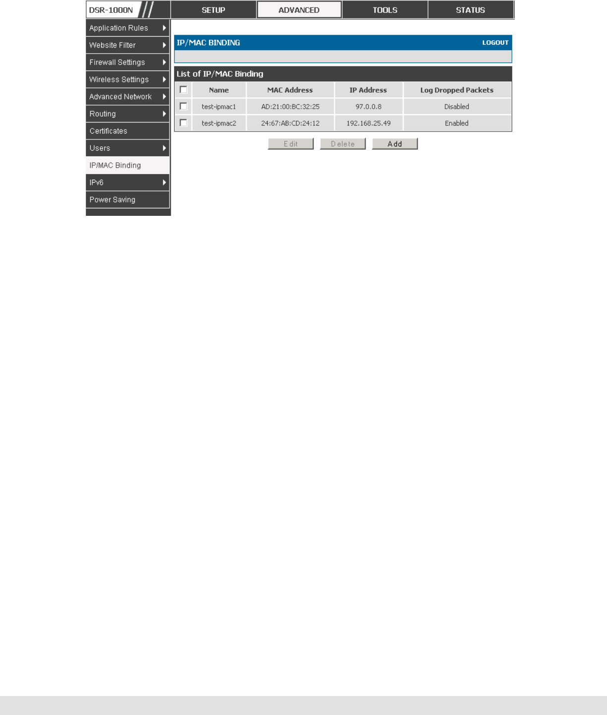
D-Link DSR Series Router
86
Figure 46: The above example of IP/MAC Binding binds a LAN host’s MAC
Address to an IP address. If there is an IP/MAC Binding violation, the
violating packet will be dropped and logs will be captured
5.10 Intrusion Prevention (IPS)
Advanced > Advanced Network > IPS
The gateway’s Intrusion Prevention System (IPS) prevents malicious attacks
from the internet from accessing the private network. Static attack signatures
loaded to the device allow common attacks to be detected and prevented.
The checks can be enabled between the WAN and DMZ or LAN, and a
running counter will allow the administrator to see how many malicious
intrusion attempts from the WAN have been detected and prevented.
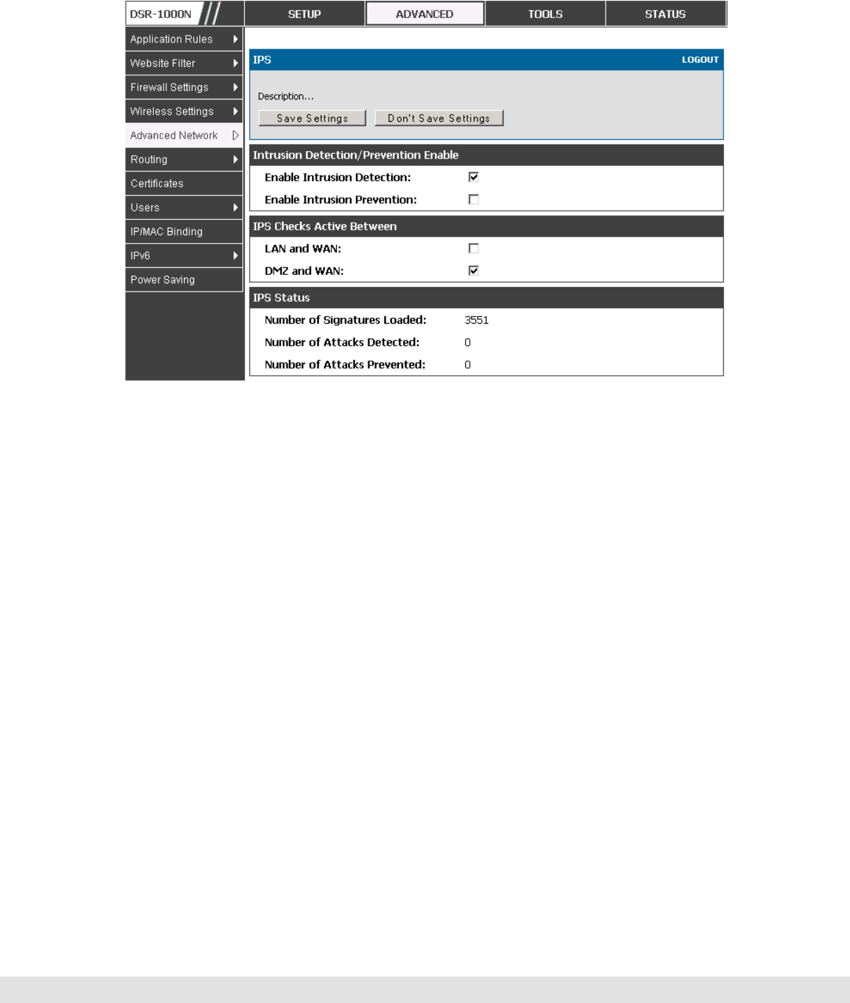
User Manual
87
Figure 47: Intrusion Prevention features on the router
5.10.1 Protecting from Internet Attacks
Advanced > Advanced Network > Attack Checks
Attacks can be malicious security breaches or unintentional network issues
that render the router unusable. Attack checks allow you to manage WAN
security threats such as continual ping requests and discovery via ARP scans.
TCP and UDP flood attack checks can be enabled to manage extreme usage
of WAN resources.
Additionally certain Denial-of-Service (DoS) attacks can be blocked. These
attacks, if uninhibited, can use up processing power and bandwidth and
prevent regular network services from running normally. ICMP packet
flooding, SYN traffic flooding, and Echo storm thresholds can be configured to
temporarily suspect traffic from the offending source.
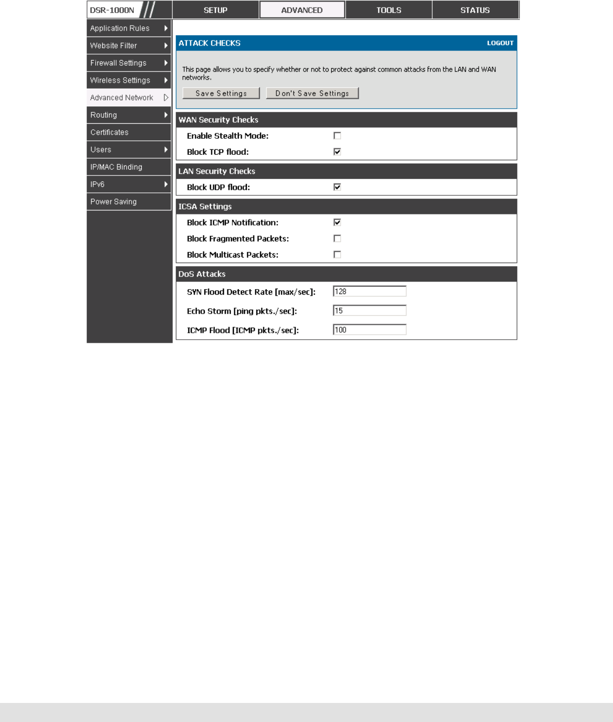
D-Link DSR Series Router
88
Figure 48: Protecting the router and LAN from internet attacks

User Manual
89
6. IPsec VPN
A VPN provides a secure communication channel (“tunnel”) between two gateway
routers or a remote PC client. The following types of tunnels can be created:
Gateway-to-gateway VPN: to connect two or more routers to secure traffic
between remote sites.
Remote Client (client-to-gateway VPN tunnel): A remote client initiates a VPN
tunnel as the IP address of the remote PC client is not known in advance. The
gateway in this case acts as a responder.
Remote client behind a NAT router: The client has a dynamic IP address and is
behind a NAT Router. The remote PC client at the NAT router initiates a VPN
tunnel as the IP address of the remote NAT router is not known in advance. The
gateway WAN port acts as responder.
6.1 VPN Wizard
Setup > Wizard > VPN Wizard
You can use the VPN wizard to quickly create both IKE and VPN policies.
Once the IKE or VPN policy is created, you can modify it as required.
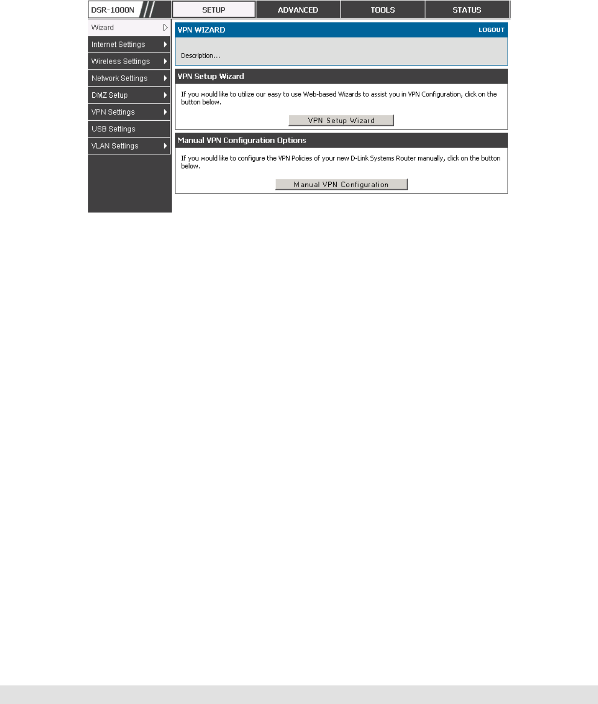
D-Link DSR Series Router
90
Figure 49: VPN Wizard launch screen
To easily establish a VPN tunnel using VPN Wizard, follow the steps below:
1. Step 1: Select the VPN tunnel type to create
The tunnel can either be a gateway to gateway connection (site-to-site) or a
tunnel to a host on the internet (remote access).
Set the Connection Name and pre-shared key: the connection name is used for
management, and the pre-shared key will be required on the VPN client or
gateway to establish the tunnel
Determine the local gateway for this tunnel; if there is more than 1 WAN
configured the tunnel can be configured for either of the gateways.
2. Step 2: Configure Remote and Local WAN address for the tunnel endpoints
Remote Gateway Type: identify the remote endpoint of the tunnel by FQDN or
static IP address
Remote WAN IP address / FQDN: This field is enabled only if the peer you are
trying to connect to is a Gateway. For VPN Clients, this IP address or Internet
Name is determined when a connection request is received from a client.
User Manual
91
Local Gateway Type: identify this router’s endpoint of the tunnel by FQDN or
static IP address
Local WAN IP address / FQDN: This field can be left blank if you are not using
a different FQDN or IP address than the one specified in the WAN port’s
configuration.
3. Step 3: Configure the Secure Connection Remote Accessibility fields to identify
the remote network:
Remote LAN IP address: address of the LAN behind the peer gateway
Remote LAN Subnet Mask: the subnet mask of the LAN behind the peer
Note: The IP address range used on the remote LAN must be different from
the IP address range used on the local LAN.
4. Step4: review the settings and click Connect to establish the tunnel.
The Wizard will create a corresponding IKE policy with the following default
values for a VPN Client or Gateway policy (these can be accessed from a link
on the Wizard page):
Parameter Default value from Wizard
Exchange Mode Aggressive (Client policy ) or Main (Gateway policy)
ID Type FQDN
Local WAN ID wan_local.com (only applies to Client policies)
Remote WAN ID wan_remote.com (only applies to Client policies)
Encryption Algorithm 3DES
Authentication Algorithm SHA-1
Authentication Method Pre-shared Key
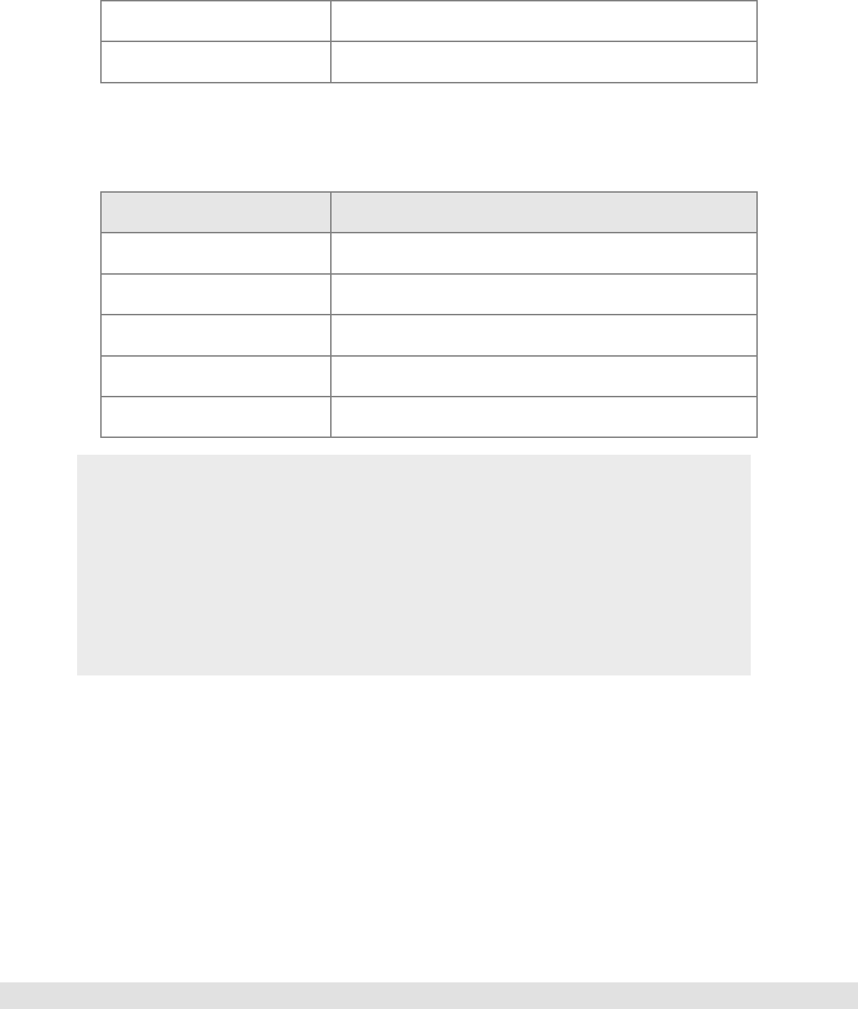
D-Link DSR Series Router
92
Key-Group DH-Group 2(1024 bit)
Life Time 24 hours
As well, the Wizard will create a matching VPN policy to the IKE policy with
the following default values:
Parameter Default value from Wizard
Encryption Algorithm 3DES
Authentication Algorithm SHA-1
Life Time 8 hours
PFS Key Group DH-Group 2(1024 bit)
NETBIOS Enabled (only applies to Gateway policies)
The VPN Wizard is the recommended method to set up corresponding IKE
and VPN policies for establishing a VPN tunnel. Once the Wizard creates
the matching IKE and VPN policies, one can modify the required fields
through the edit link. Advanced users can create an IKE policy from the
Add link but must be sure to use compatible encryption, authentication, and
key-group parameters for the VPN policy. Refer to the online help for
details.
6.2 Configuring IKE Policies
Setup > VPN Settings > IPsec > IKE Policies
The Internet Key Exchange (IKE) protocol dynamically exchanges keys
between two IPsec hosts. You can create IKE policies to define the security
parameters such as authentication of the peer, encryption algorithms, etc. to
be used in this process.

User Manual
93
IKE policies can be created by clicking “Add” on the VPN > IKE Policies web
page.
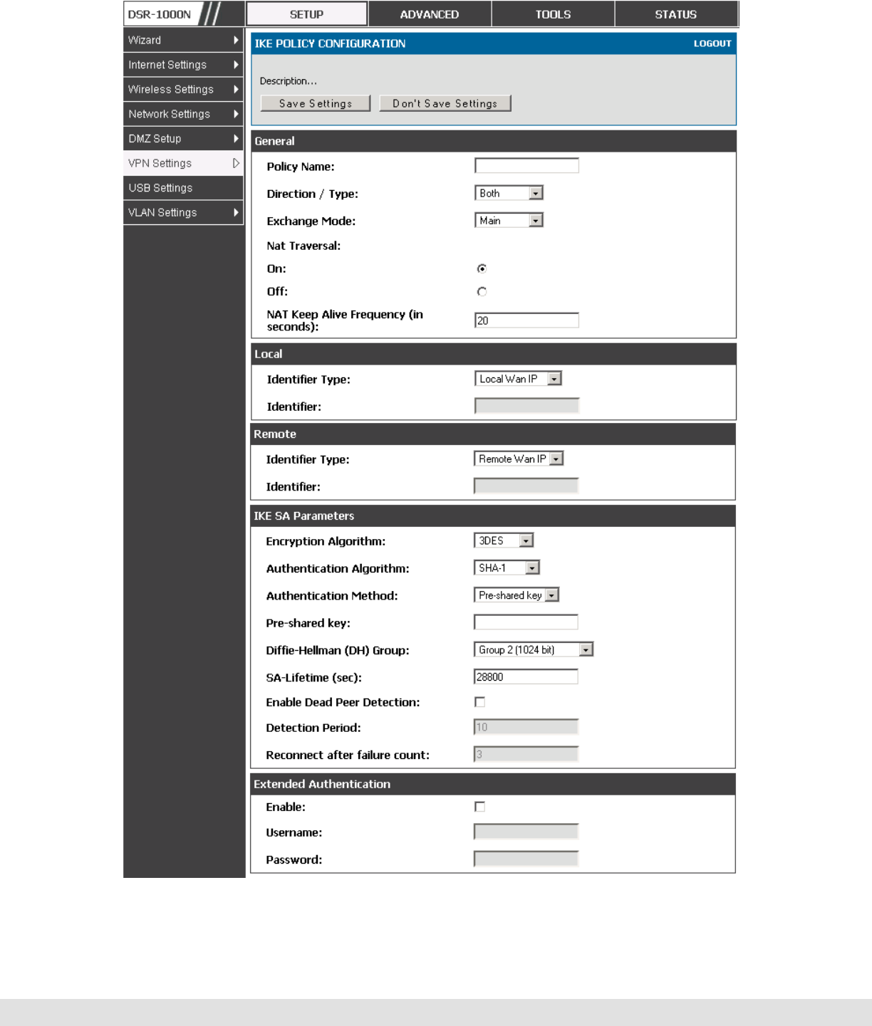
D-Link DSR Series Router
94
Figure 50: IKE policy created by the VPN Wizard then modified manually

User Manual
95
6.2.1 Configuring an IKE Policy using XAUTH
You can also configure extended authentication (XAUTH). Rather than
configure a unique VPN policy for each user, you can configure the VPN
gateway router to authenticate users from a stored list of user accounts or
with an external authentication server such as a RADIUS server. With a user
database, user accounts created in the router are used to authenticate
users.
With a configured RADIUS server, the router connects to a RADIUS server
and passes to it the credentials that it receives from the VPN client. You can
secure the connection between the router and the RADIUS server with the
authentication protocol supported by the server (PAP or CHAP). For RADIUS
– PAP, the router first checks in the user database to see if the user
credentials are available; if they are not, the router connects to the RADIUS
server.
6.3 Configuring VPN Policies
Setup > VPN Settings > IPsec > VPN Policies
The VPN policy is one half of the IKE/VPN policy pair required to establish a
VPN tunnel. The IP addresses of the machine or machines on the two VPN
endpoints are configured here, along with the policy parameters required to
secure the tunnel.
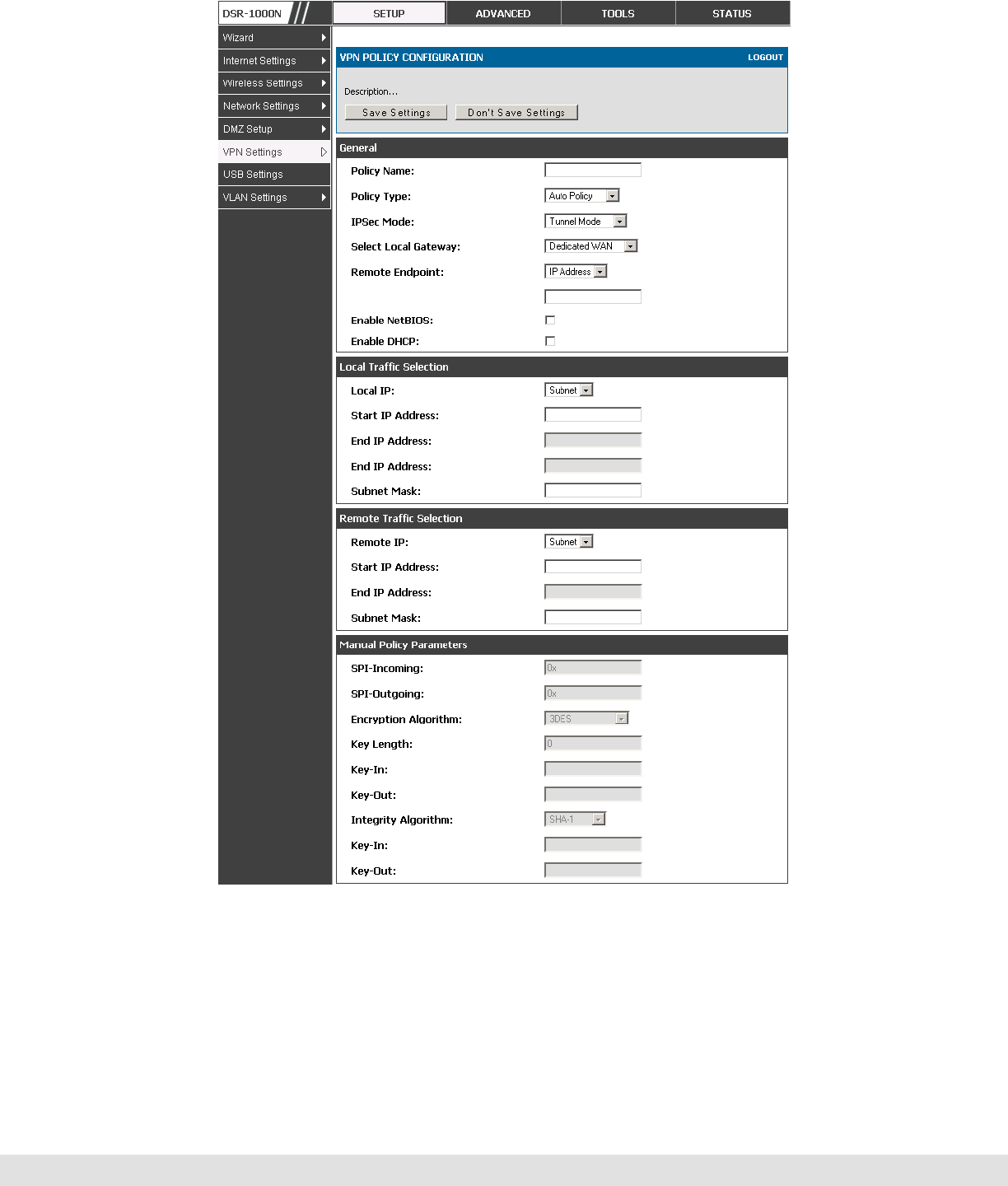
D-Link DSR Series Router
96
Figure 51: VPN policy created by the VPN Wizard then modified manually
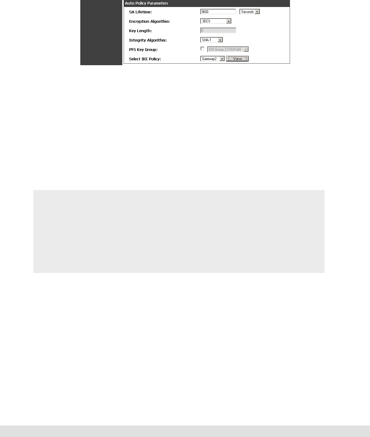
User Manual
97
Figure 52: VPN policy created by the VPN Wizard then modified manually
(continued)
6.4 Configuring VPN clients
Remote VPN clients must be configured with the same VPN policy parameters
used in the VPN tunnel that the client wishes to use: encryption,
authentication, life time, and PFS key-group. Upon establishing these
authentication parameters, the VPN Client user database must also be
populated with an account to give a user access to the tunnel.
VPN client software is required to establish a VPN tunnel between the
router and remote endpoint. Open source software (such as OpenVPN or
Openswan) as well as Microsoft IPSec VPN software can be configured with
the required IKE policy parameters to establish an IPSec VPN tunnel. Refer
to the client software guide for detailed instructions on setup as well as the
router’s online help.
The user database contains the list of VPN user accounts that are authorized
to use a given VPN tunnel. Alternatively VPN tunnel users can be
authenticated using a configured Radius database. Refer to the online help to
determine how to populate the user database and/or configure RADIUS
authentication.
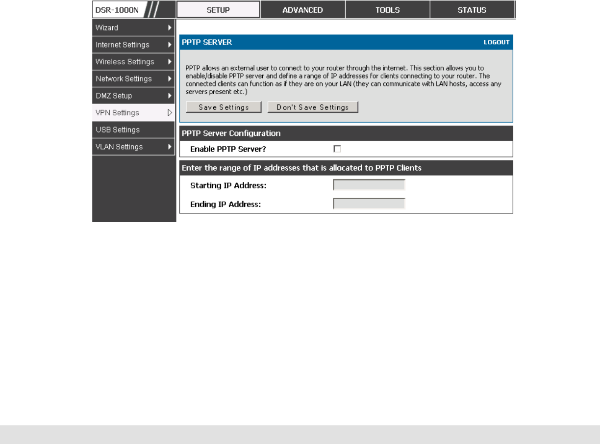
D-Link DSR Series Router
98
6.5 PPTP / L2TP Tunnels
This router supports VPN tunnels from either PPTP or L2TP ISP servers. The
router acts as a broker device to allow the ISP's server to create a TCP
control connection between the LAN VPN client and the VPN server.
6.5.1 PPTP Tunnel Support
Setup > VPN Settings > PPTP > PPTP Server
A PPTP VPN can be established through this router. If the WAN mode has
configured a PPTP ISP, then LAN hosts on this router can connect directly to
the PPTP server. The PPTP server will indicate the range of IP addresses in
your LAN to assign to LAN side VPN clients to allow the PPTP clients to
establish a direct tunnel to the WAN side PPTP server.
Figure 53: PPTP tunnel configuration – PPTP Server
6.5.2 L2TP Tunnel Support
Setup > VPN Settings > L2TP > L2TP Server
A L2TP VPN can be established through this router If the WAN mode has
configured a L2TP ISP, then LAN hosts on this router can connect directly to
the L2TP server. The L2TP server will indicate the range of IP addresses in
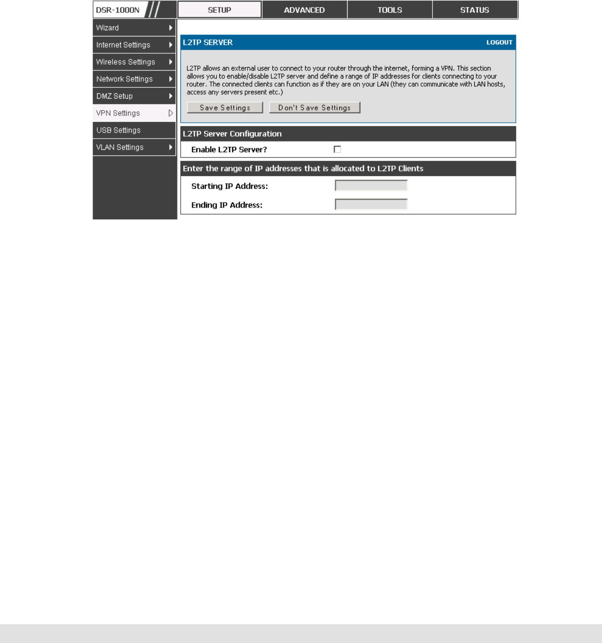
User Manual
99
your LAN to assign to LAN side VPN clients to allow the L2TP clients to
establish a direct tunnel to the WAN side L2TP server.
Figure 54: L2TP tunnel configuration – L2TP Server

101
7. SSL VPN
The router provides an intrinsic SSL VPN feature as an alternate to the standard
IPsec VPN. SSL VPN differs from IPsec VPN mainly by removing the requirement
of a pre-installed VPN client on the remote host. Instead, users can securely login
through the SSL User Portal using a standard web browser and receive access to
configured network resources within the corporate LAN. The router supports
multiple concurrent sessions to allow remote users to access the LAN over an
encrypted link through a customizable user portal interface, and each SSL VPN
user can be assigned unique privileges and network resource access levels.
The remote user can be provided different options for SSL service through this
router:
VPN Tunnel: The remote user’s SSL enabled browser is used in place of a VPN
client on the remote host to establish a secure VPN tunnel. A SSL VPN client
(Active-X or Java based) is installed in the remote host to allow the client to join
the corporate LAN with pre-configured access/policy privileges. At this point a
virtual network interface is created on the user’s host and this will be assigned
an IP address and DNS server address from the router. Once established, the
host machine can access allocated network resources.
Port Forwarding: A web-based (ActiveX or Java) client is installed on the client
machine again. Note that Port Forwarding service only supports TCP
connections between the remote user and the router. The router administrator
can define specific services or applications that are available to remote port
forwarding users instead of access to the full LAN like the VPN tunnel.
ActiveX clients are used when the remote user accesses the portal using
the Internet Explorer browser. The Java client is used for other browsers
like Mozilla Firefox, Netscape Navigator, Google Chrome, and Apple Safari.
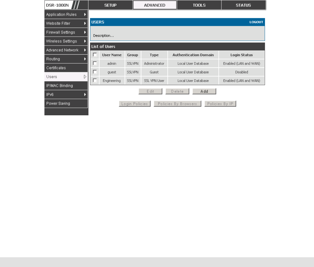
D-Link DSR Series Router
102
7.1 Users, Groups, and Domains
Advanced > Users > Users
Authentication of the remote SSL VPN user is done by the router using either
a local database on the router or external authentication servers (i.e. LDAP or
RADIUS). The remote user must specify the user, group and domain when
logging in to the SSL VPN router. One or more users are members of a
Group. One or more Groups belong to an authentication Domain.
Figure 55: Available Users with login status and associated Group/Domain
Advanced > Users > Domains
The Domain determines the authentication method (local user database,
external server) to be used when validating the remote user’s connection. As
well the Domain determines the portal layout presented to the remote SSL
user. Since the portal layout assigns access to SSL VPN tunnel and/or SSL
VPN Port Forwarding features, the domain is essential in defining the
authentication and features exposed to SSL users.

User Manual
103
Advanced > Users > Groups
Groups are used to assign access policies to a set of SSL users within a
domain. Groups are domain subsets that can be seen as types of SSL users;
some groups require access to all available network resources and some can
be provided access to a select few. With groups, a very secure hierarchy of
SSL VPN remote access can be created for all types of users with minimal
number of policies to configure.
You must create a Domain first, and then a new Group can be created and
assigned to the Domain. The last step is to add specific SSL VPN users to
an already-configured Group.
7.1.1 User Types and Passwords
Advanced > Users > Users
User level policies can be specified by browser, IP address of the host, and
whether the user can login to the router’s GUI in addition to the SSL VPN
portal. The following user types are assigned to a user that reaches the GUI
login screen from the LAN or WAN:
Administrator: This is the router’s super-user, and can manage the router, use
SSL VPN to access network resources, and login to L2TP/PPTP servers on
the WAN. There will always be one default administrator user for the GUI.
Guest (read only): The guest user gains read only access to the GUI to observe
and review configuration settings. The guest does not have SSL VPN access.
SSL VPN User: This user has access to the SSL VPN services as determined
by the group policies and authentication domain of which it is a member. The
domain-determined SSL VPN portal will be displayed when logging in with this
user type.
XAuth User: This user’s authentication is performed by an externally configured
RADIUS or other Enterprise server. It is not part of the local user database.
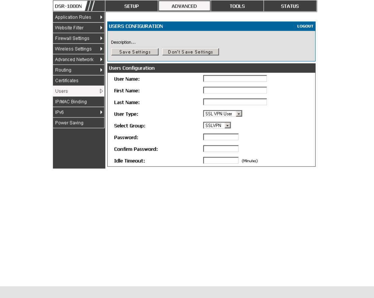
D-Link DSR Series Router
104
L2TP User: These are L2TP VPN tunnel LAN users that can establish a tunnel
with the L2TP server on the WAN.
PPTP User: These are PPTP VPN tunnel LAN users that can establish a tunnel
with the PPTP server on the WAN.
Local User: This user’s authentication domain is located on the router itself.
Once the user type is determined, you can define/modify the password and
idle login timeout for the user. It is recommended that passwords contains no
dictionary words from any language, and is a mixture of letters (both
uppercase and lowercase), numbers, and symbols. The password can be up
to 30 characters.
Figure 56: User configuration options
7.2 Using SSL VPN Policies
Setup > VPN Settings > SSL VPN Server > SSL VPN Policies
SSL VPN Policies can be created on a Global, Group, or User level. User
level policies take precedence over Group level policies and Group level
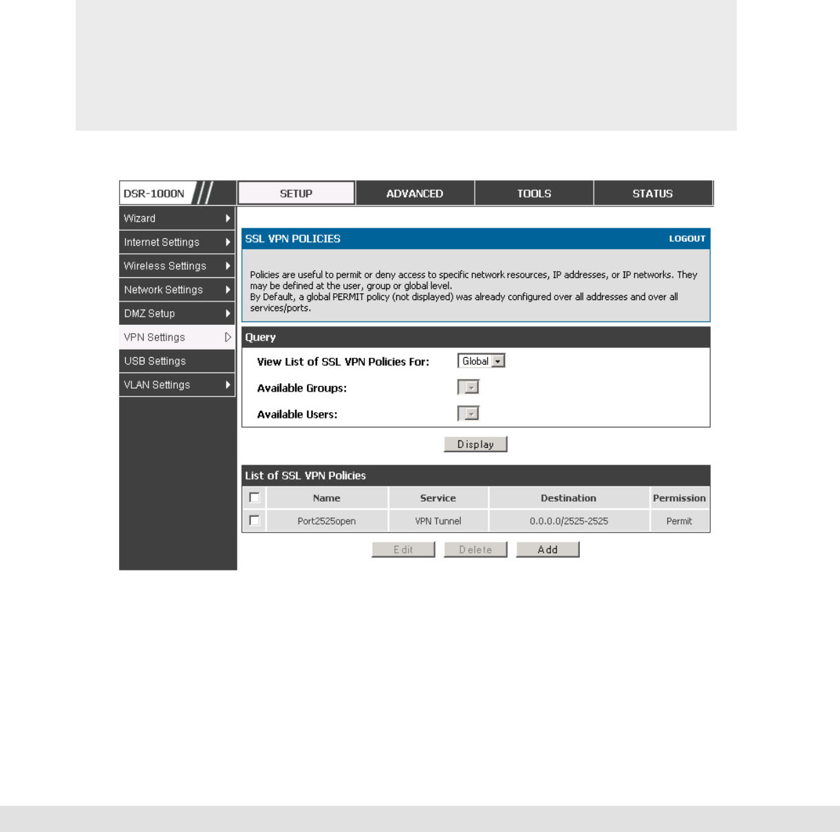
User Manual
105
policies take precedence over Global policies. These policies can be applied
to a specific network resource, IP address or ranges on the LAN, or to
different SSL VPN services supported by the router. The List of Available
Policies can be filtered based on whether it applies to a user, group, or all
users (global).
A more specific policy takes precedence over a generic policy when both
are applied to the same user/group/global domain. I.e. a policy for a
specific IP address takes precedence over a policy for a range of addresses
containing the IP address already referenced.
Figure 57: List of SSL VPN polices (Global filter)
To add a SSL VPN policy, you must first assign it to a user, group, or make it
global (i.e. applicable to all SSL VPN users). If the policy is for a group, the
available configured groups are shown in a drop down menu and one must be

D-Link DSR Series Router
106
selected. Similarly, for a user defined policy a SSL VPN user must be chosen
from the available list of configured users.
The next step is to define the policy details. The policy name is a unique
identifier for this rule. The policy can be assigned to a specific Network
Resource (details follow in the subsequent section), IP address, IP network,
or all devices on the LAN of the router. Based on the selection of one of
these four options, the appropriate configuration fields are required (i.e.
choosing the network resources from a list of defined resources, or defining
the IP addresses). For applying the policy to addresses the port range/port
number can be defined.
The final steps require the policy permission to be set to either permit or deny
access to the selected addresses or network resources. As well the policy
can be specified for one or all of the supported SSL VPN services (i.e. VPN
tunnel)
Once defined, the policy goes into effect immediately. The policy name, SSL
service it applies to, destination (network resource or IP addresses) and
permission (deny/permit) is outlined in a list of configured policies for the
router.
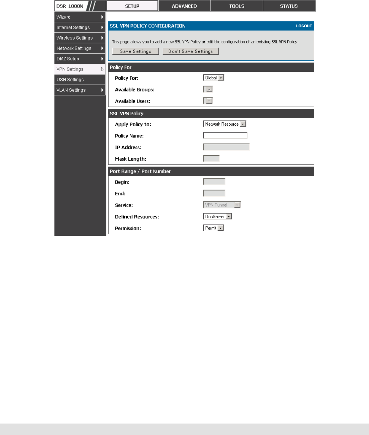
User Manual
107
Figure 58: SSL VPN policy configuration
7.2.1 Using Network Resources
Setup > VPN Settings > SSL VPN Server > Resources
Network resources are services or groups of LAN IP addresses that are used
to easily create and configure SSL VPN policies. This shortcut saves time
when creating similar policies for multiple remote SSL VPN users.
Adding a Network Resource involves creating a unique name to identify the
resource and assigning it to one or all of the supported SSL services. Once
this is done, editing one of the created network resources allows you to
configure the object type (either IP address or IP range) associated with the
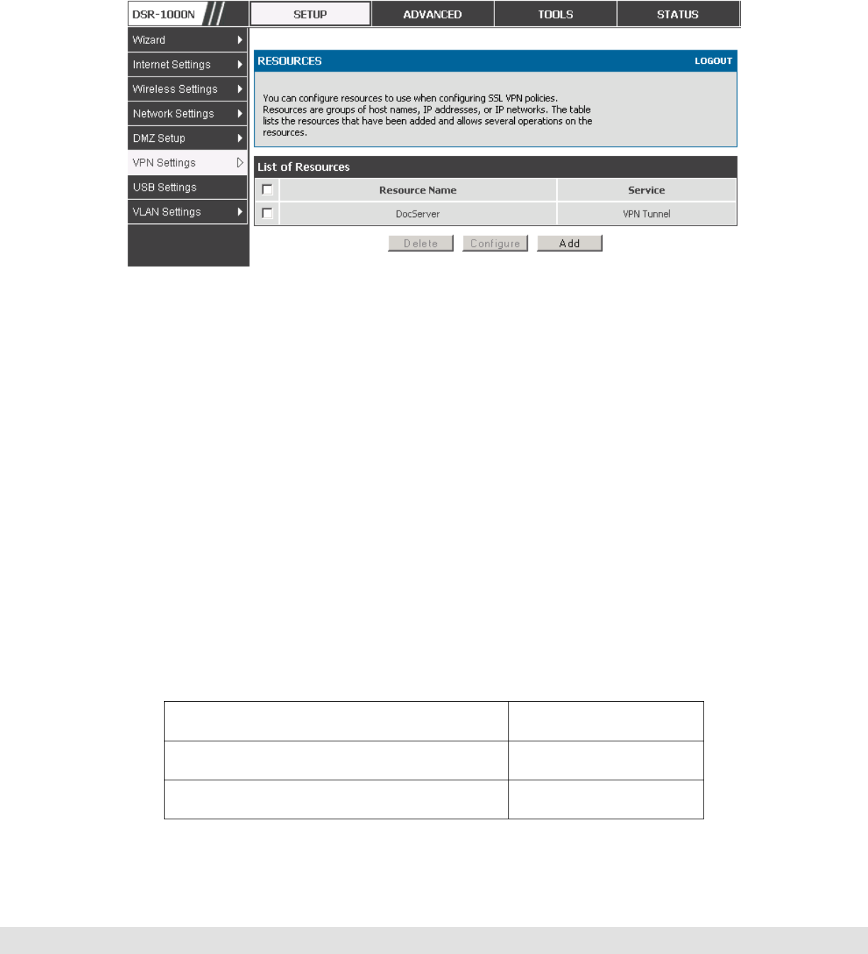
D-Link DSR Series Router
108
service. The Network Address, Mask Length, and Port Range/Port Number
can all be defined for this resource as required.
Figure 59: List of configured resources, which are available to assign to
SSL VPN policies
7.3 Application Port Forwarding
Setup > VPN Settings > SSL VPN Server > Port Forwarding
Port forwarding allows remote SSL users to access specified network
applications or services after they login to the User Portal and launch the Port
Forwarding service. Traffic from the remote user to the router is detected and
re-routed based on configured port forwarding rules.
Internal host servers or TCP applications must be specified as being made
accessible to remote users. Allowing access to a LAN server requires
entering the local server IP address and TCP port number of the application
to be tunneled. The table below lists some common applications and
corresponding TCP port numbers:
TCP Application Port Number
FTP Data (usually not needed) 20
FTP Control Protocol 21

User Manual
109
SSH 22
Telnet 23
SMTP (send mail) 25
HTTP (web) 80
POP3 (receive mail) 110
NTP (network time protocol) 123
Citrix 1494
Terminal Services 3389
VNC (virtual network computing) 5900 or 5800
As a convenience for remote users, the hostname (FQDN) of the network
server can be configured to allow for IP address resolution. This host name
resolution provides users with easy-to-remember FQDN’s to access TCP
applications instead of error-prone IP addresses when using the Port
Forwarding service through the SSL User Portal.
Defining the hostname is optional as minimum requirement for port
forwarding is identifying the TCP application and local server IP address.
The local server IP address of the configured hostname must match the IP
address of the configured application for port forwarding.
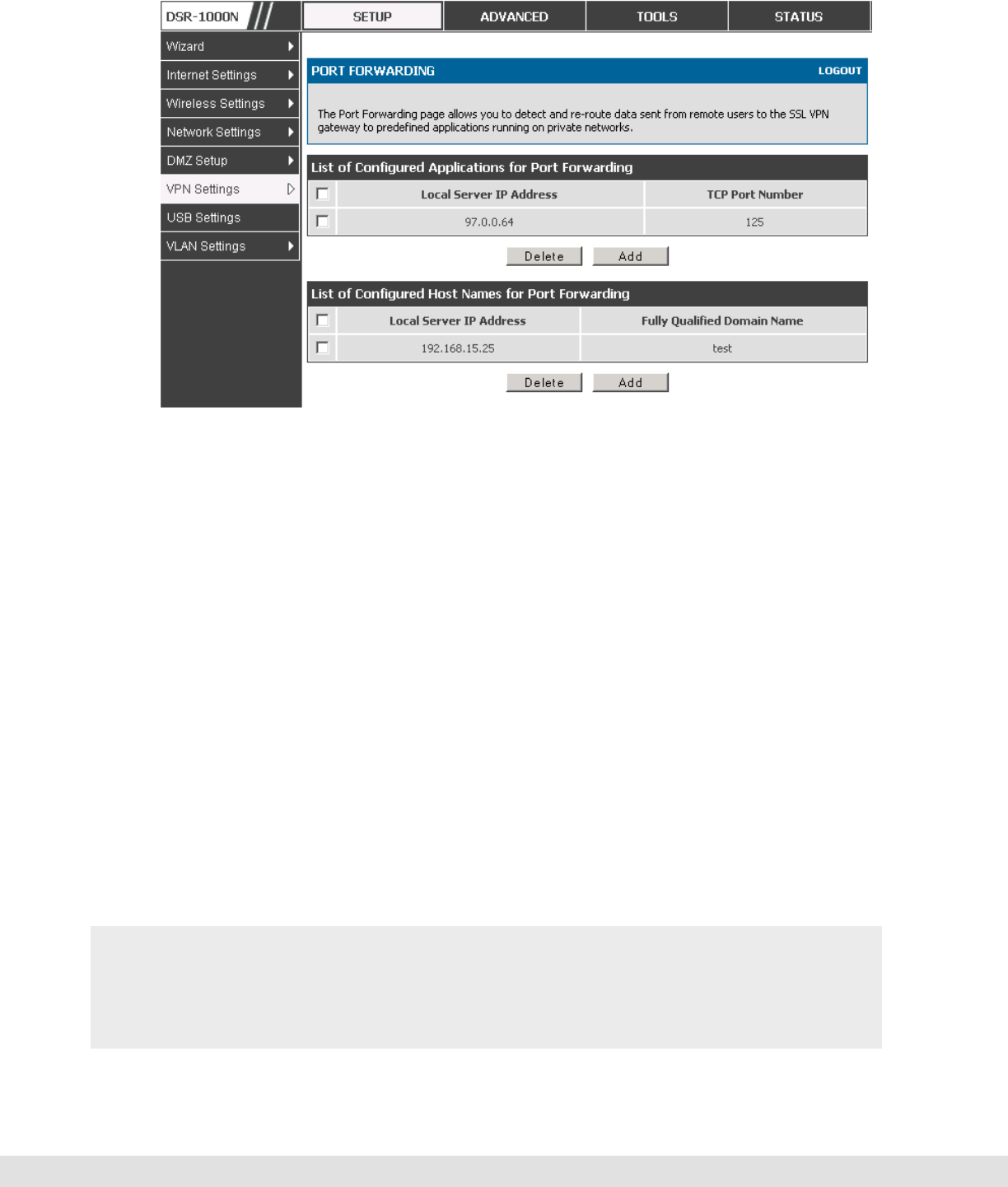
D-Link DSR Series Router
110
Figure 60: List of Available Applications for SSL Port Forwarding
7.4 SSL VPN Client Configuration
Setup > VPN Settings > SSL VPN Client > SSL VPN Client
An SSL VPN tunnel client provides a point-to-point connection between the
browser-side machine and this router. When a SSL VPN client is launched
from the user portal, a "network adapter" with an IP address from the
corporate subnet, DNS and WINS settings is automatically created. This
allows local applications to access services on the private network without
any special network configuration on the remote SSL VPN client machine.
It is important to ensure that the virtual (PPP) interface address of the VPN
tunnel client does not conflict with physical devices on the LAN. The IP
address range for the SSL VPN virtual network adapter should be either in a
different subnet or non-overlapping range as the corporate LAN.
The IP addresses of the client’s network interfaces (Ethernet, Wireless, etc.)
cannot be identical to the router’s IP address or a server on the corporate
LAN that is being accessed through the SSL VPN tunnel.
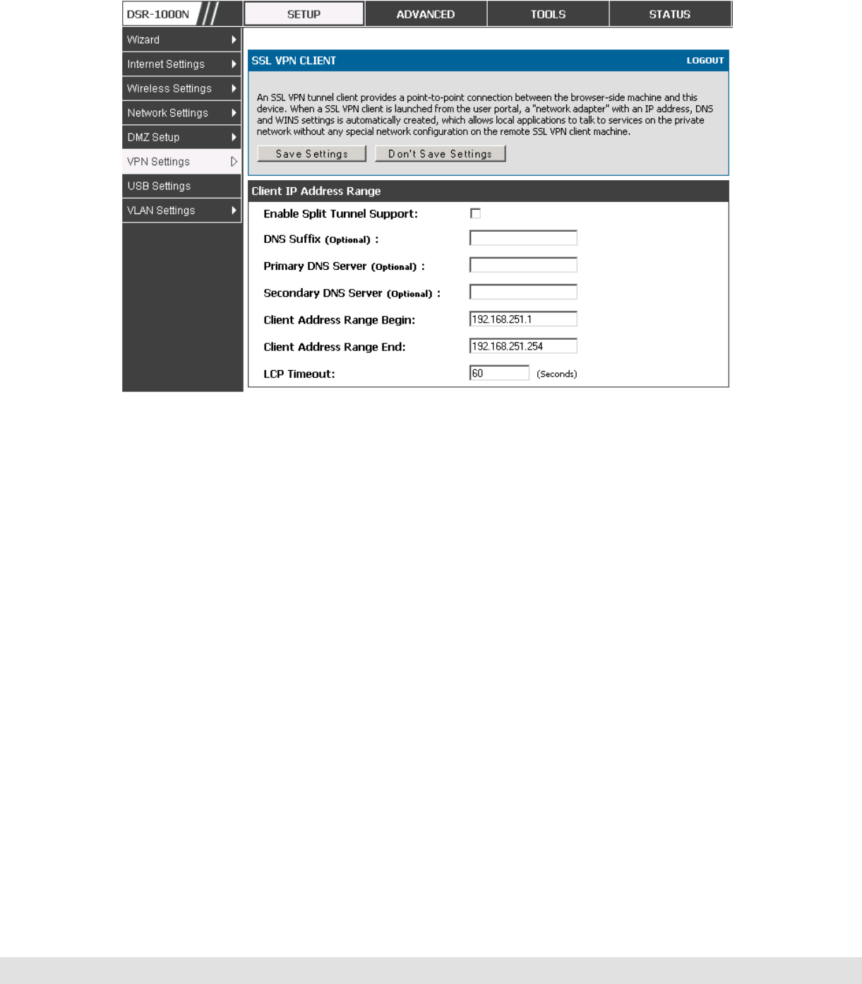
User Manual
111
Figure 61: SSL VPN client adapter and access configuration
The router allows full tunnel and split tunnel support. Full tunnel mode just
sends all traffic from the client across the VPN tunnel to the router. Split
tunnel mode only sends traffic to the private LAN based on pre-specified
client routes. These client routes give the SSL client access to specific private
networks, thereby allowing access control over specific LAN services.
Setup > VPN Settings > SSL VPN Client > Configured Client Routes
If the SSL VPN client is assigned an IP address in a different subnet than the
corporate network, a client route must be added to allow access to the private
LAN through the VPN tunnel. As well a static route on the private LAN’s
firewall (typically this router) is needed to forward private traffic through the
VPN Firewall to the remote SSL VPN client.
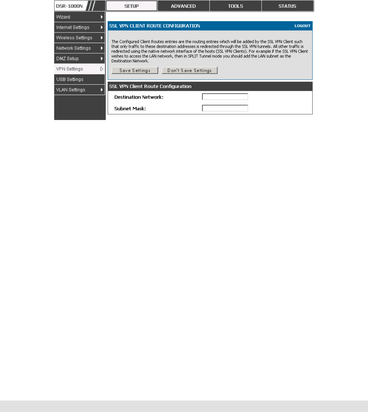
D-Link DSR Series Router
112
Figure 62: Configured client routes only apply in split tunnel mode.
7.5 User Portal
Setup > VPN Settings > SSL VPN Client > SSL VPN Client Portal
When remote users want to access the private network through an SSL tunnel
(either using the Port Forwarding or VPN tunnel service), they login through a
user portal. This portal provides the authentication fields to provide the
appropriate access levels and privileges as determined by the router
administrator. The domain where the user account is stored must be
specified, and the domain determines the authentication method and portal
layout screen presented to the remote user.
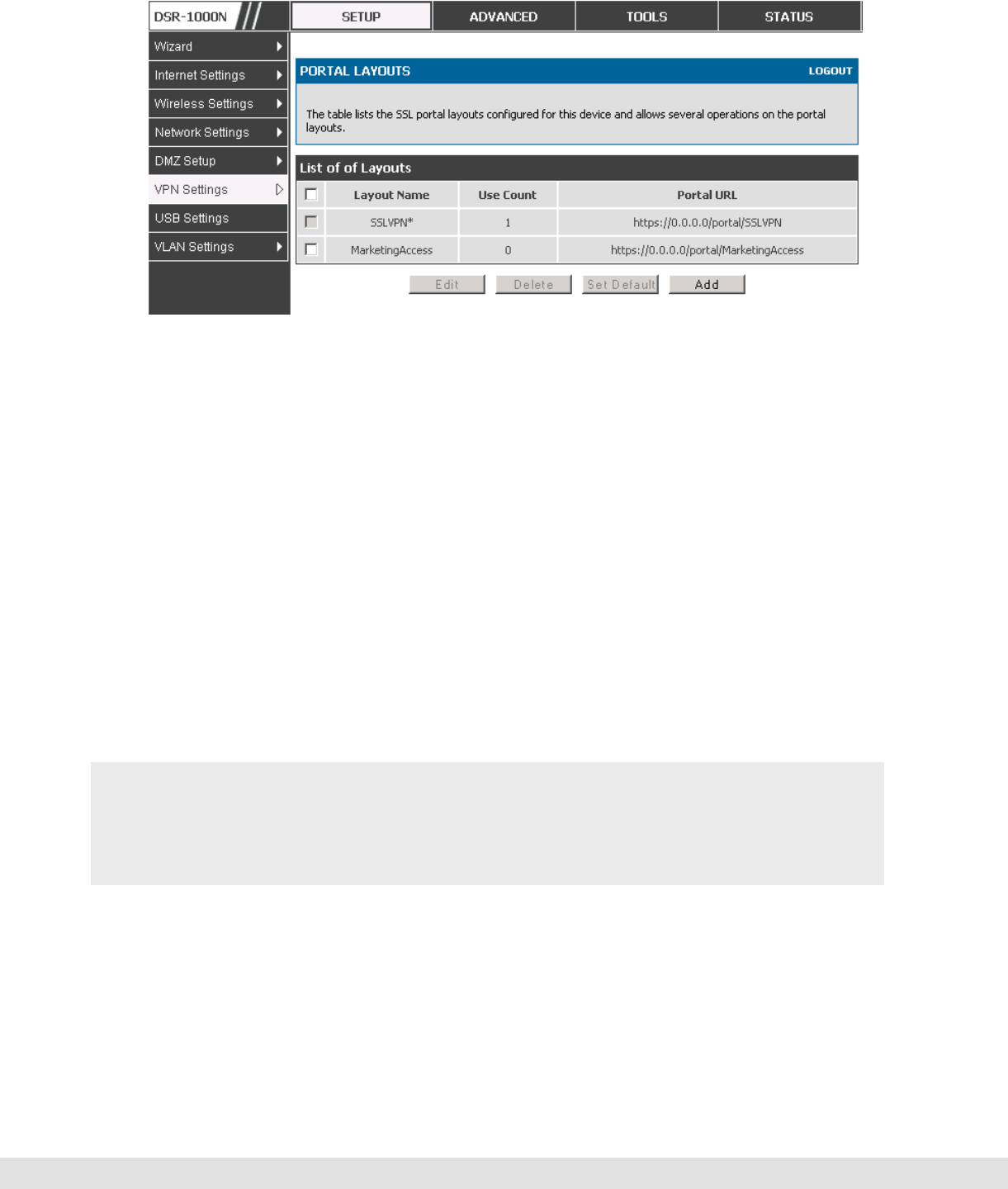
User Manual
113
Figure 63: List of configured SSL VPN portals. The configured portal can
then be associated with an authentication domain
7.5.1 Creating Portal Layouts
Setup > VPN Settings > SSL VPN Server > Portal Layouts
The router allows you to create a custom page for remote SSL VPN users
that is presented upon authentication. There are various fields in the portal
that are customizable for the domain, and this allows the router administrator
to communicate details such as login instructions, available services, and
other usage details in the portal visible to remote users. During domain
setup, configured portal layouts are available to select for all users
authenticated by the domain.
The default portal LAN IP address is https://192.168.10.1/scgi-
bin/userPortal/portal. This is the same page that opens when the “User
Portal” link is clicked on the SSL VPN menu of the router GUI.
The router administrator creates and edits portal layouts from the
configuration pages in the SSL VPN menu. The portal name, title, banner
name, and banner contents are all customizable to the intended users for
this portal. The portal name is appended to the SSL VPN portal URL. As
well, the users assigned to this portal (through their authentication domain)
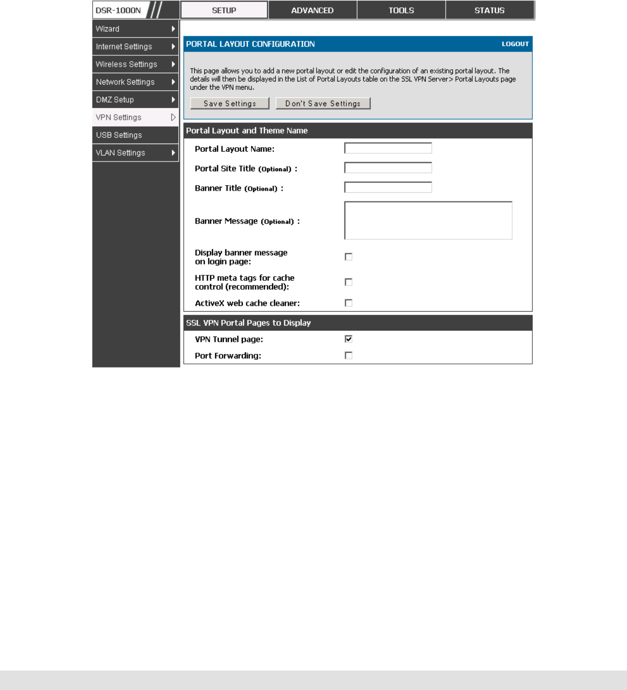
D-Link DSR Series Router
114
can be presented with one or more of the router’s supported SSL services
such as the VPN Tunnel page or Port Forwarding page.
Figure 64: SSL VPN Portal configuration
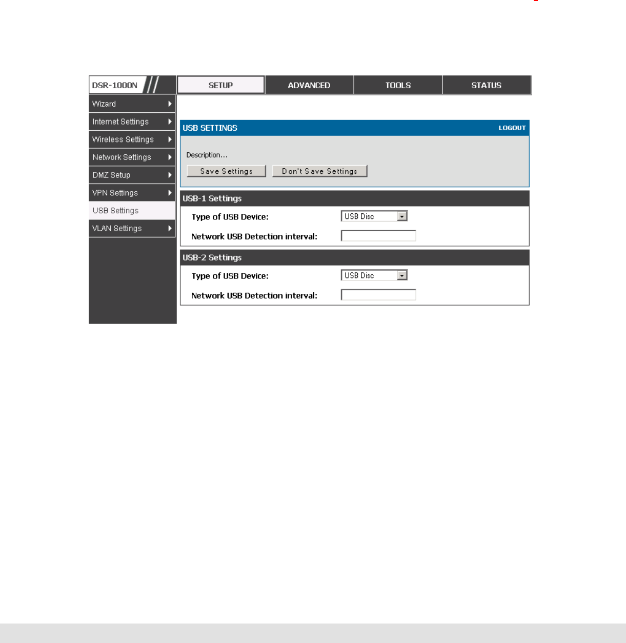
User Manual
115
8. Advanced Configuration Tools
8.1 USB Device Setup
There are two USB ports on the DSR router. The port supports a 3G modem
where the USB dongle is used as a secondary WAN interface. Additionally,
the port can be used for a USB storage device if USB Disc is type is selected.
This storage can be accessed by LAN devices if appropriate policies are
configured.
Figure 65: USB device configuration
8.2 Authentication Certificates
This gateway uses digital certificates for IPsec VPN authentication as well as SSL
validation (for HTTPS and SSL VPN authentication). You can obtain a digital
certificate from a well known Certificate Authority (CA) such as VeriSign, or
generate and sign your own certificate using functionality available on this
gateway. The gateway comes with a self-signed certificate, and this can be
replaced by one signed by a CA as per your networking requirements. A CA
certificate provides strong assurance of the server’s identity and is a requirement
for most corporate network VPN solutions.

D-Link DSR Series Router
116
The certificates menu allows you to view a list of certificates (both from a CA and
self-signed) currently loaded on the gateway. The following certificate data is
displayed in the list of Trusted (CA) certificates:
CA Identity (Subject Name): The certificate is issued to this person or
organization
Issuer Name: This is the CA name that issued this certificate
Expiry Time: The date after which this Trusted certificate becomes invalid
A self certificate is a certificate issued by a CA identifying your device (or self-
signed if you don’t want the identity protection of a CA). The Active Self Certificate
table lists the self certificates currently loaded on the gateway. The following
information is displayed for each uploaded self certificate:
Name: The name you use to identify this certificate, it is not displayed to IPSec
VPN peers or SSL users.
Subject Name: This is the name that will be displayed as the owner of this
certificate. This should be your official registered or company name, as IPsec
or SSL VPN peers are shown this field.
Serial Number: The serial number is maintained by the CA and used to identify
this signed certificate.
Issuer Name: This is the CA name that issued (signed) this certificate
Expiry Time: The date after which this signed certificate becomes invalid – you
should renew the certificate before it expires.
To request a self certificate to be signed by a CA, you can generate a Certificate
Signing Request from the gateway by entering identification parameters and
passing it along to the CA for signing. Once signed, the CA’s Trusted Certificate
and signed certificate from the CA are uploaded to activate the self-certificate
validating the identity of this gateway. The self certificate is then used in IPsec
and SSL connections with peers to validate the gateway’s authenticity.
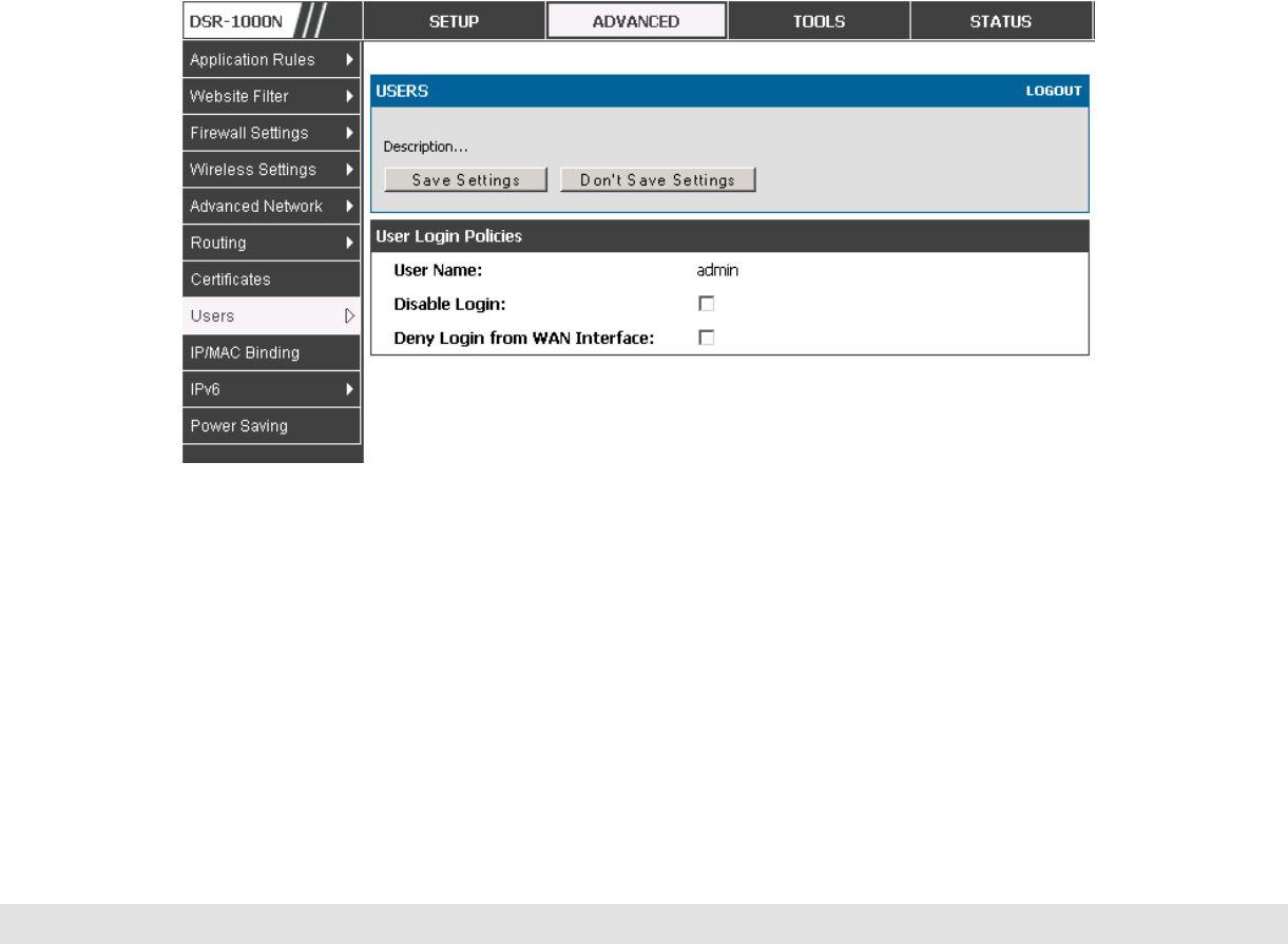
User Manual
117
9. Administration & Management
9.1 Configuration Access Control
The primary means to configure this gateway via the browser-independent
GUI. The GUI can be accessed from LAN node by using the gateway’s LAN
IP address and HTTP, or from the WAN by using the gateway’s WAN IP
address and HTTPS (HTTP over SSL).
Administrator and Guest users are permitted to login to the router’s
management interface. The user type is set in the Advanced > Users >
Users page. The Admin or Guest user can be configured to access the router
GUI from the LAN or the Internet (WAN) by enabling the corresponding Login
Policy.
Figure 66: User Login policy configuration
9.1.1 Remote Management
Both HTTPS and telnet access can be restricted to a subset of IP addresses.
The router administrator can define a known PC, single IP address or range
of IP addresses that are allowed to access the GUI with HTTPS. The opened
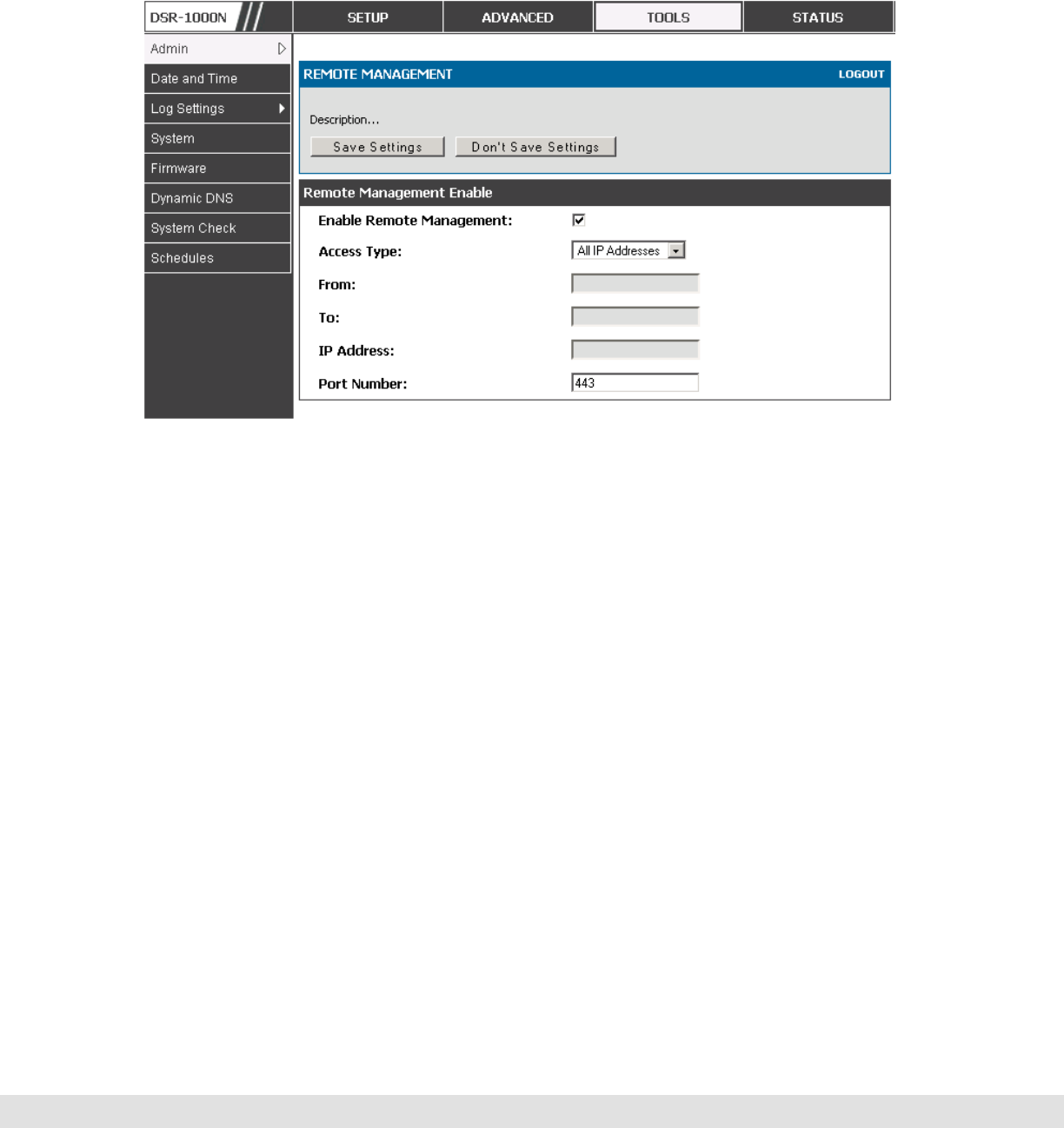
D-Link DSR Series Router
118
port for SSL traffic can be changed from the default of 443 at the same time
as defining the allowed remote management IP address range.
Figure 67: Remote Management from the WAN
9.1.2 CLI Access
In addition to the web-based GUI, the gateway supports SSH and Telnet
management for command-line interaction. The CLI login credentials are
shared with the GUI for administrator users. To access the CLI, type “cli” in
the SSH or console prompt and login with administrator user credentials.
9.2 SNMP Configuration
Tools > Admin > SNMP
SNMP is an additional management tool that is useful when multiple routers in
a network are being managed by a central Master system. When an external
SNMP manager is provided with this router’s Management Information Base
(MIB) file, the manager can update the router’s hierarchal variables to view or
update configuration parameters. The router as a managed device has an
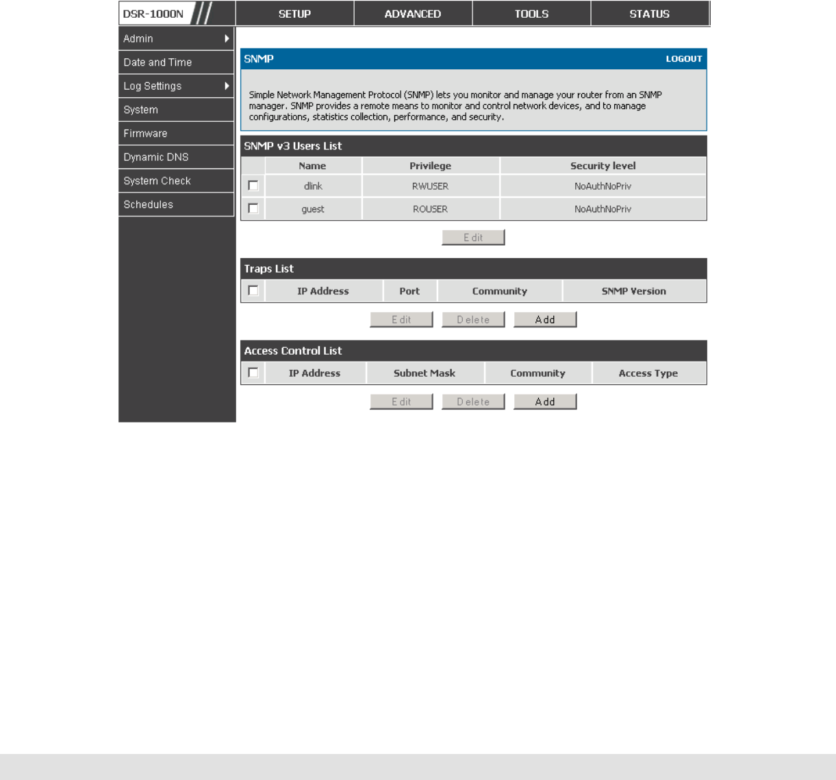
User Manual
119
SNMP agent that allows the MIB configuration variables to be accessed by
the Master (the SNMP manager). The Access Control List on the router
identifies managers in the network that have read-only or read-write SNMP
credentials. The Traps List outlines the port over which notifications from this
router are provided to the SNMP community (managers) and also the SNMP
version (v1, v2c, v3) for the trap.
Figure 68: SNMP Users, Traps, and Access Control
Tools > Admin > SNMP System Info
The router is identified by an SNMP manager via the System Information.
The identifier settings The SysName set here is also used to identify the
router for SysLog logging.
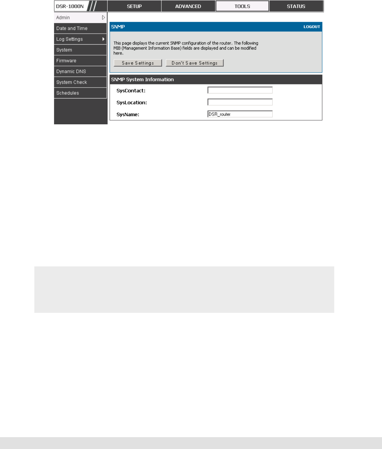
D-Link DSR Series Router
120
Figure 69: SNMP system information for this router
9.3 Configuring Time Zone and NTP
Tools > Date and Time
You can configure your time zone, whether or not to adjust for Daylight
Savings Time, and with which Network Time Protocol (NTP) server to
synchronize the date and time. You can choose to set Date and Time
manually, which will store the information on the router’s real time clock
(RTC). If the router has access to the internet, the most accurate mechanism
to set the router time is to enable NTP server communication.
Accurate date and time on the router is critical for firewall schedules, Wi-Fi
power saving support to disable APs at certain times of the day, and
accurate logging.
Please follow the steps below to configure the NTP server:
1. Select the router’s time zone, relative to Greenwich Mean Time (GMT).
2. If supported for your region, click to Enable Daylight Savings.
3. Determine whether to use default or custom Network Time Protocol (NTP)
servers. If custom, enter the server addresses or FQDN.
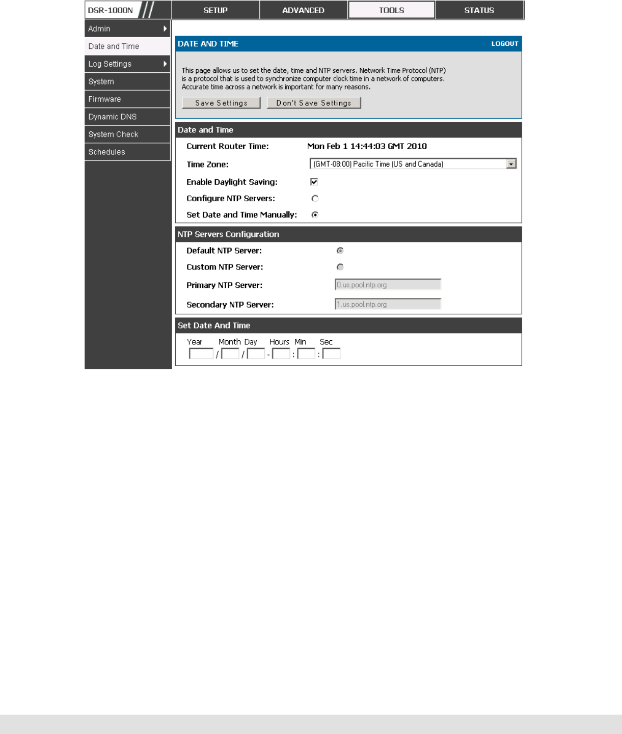
User Manual
121
Figure 70: Date, Time, and NTP server setup
9.4 Backing up and Restoring Configuration Settings
Tools > System
You can back up the router’s custom configuration settings to restore them to
a different device or the same router after some other changes. During
backup, your settings are saved as a file on your host. You can restore the
router's saved settings from this file as well. This page will also allow you
revert to factory default settings or execute a soft reboot of the router.

D-Link DSR Series Router
122
IMPORTANT! During a restore operation, do NOT try to go online, turn off
the router, shut down the PC, or do anything else to the router until the
operation is complete. This will take approximately 1 minute. Once the LEDs
are turned off, wait a few more seconds before doing anything with the
router.
For backing up configuration or restoring a previously saved configuration,
please follow the steps below:
1. To save a copy of your current settings, click the Backup button in the Save
Current Settings option. The browser initiates an export of the configuration file
and prompts to save the file on your host.
2. To restore your saved settings from a backup file, click Browse then locate the file
on the host. After clicking Restore, the router begins importing the file’s saved
configuration settings. After the restore, the router reboots automatically with the
restored settings.
3. To erase your current settings and revert to factory default settings, click the
Default button. The router will then restore configuration settings to factory
defaults and will reboot automatically. (See Appendix B for the factory default
parameters for the router).
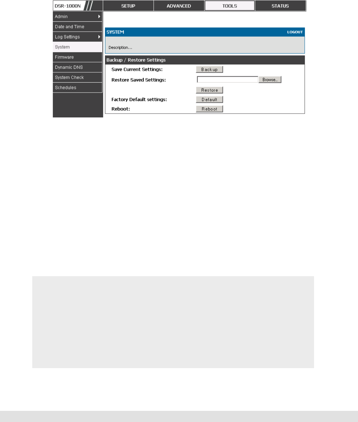
User Manual
123
Figure 71: Restoring configuration from a saved file will result in the
current configuration being overwritten and a reboot
9.5 Upgrading Router Firmware
Tools > Firmware
You can upgrade to a newer software version from the Administration web
page. In the Firmware Upgrade section, to upgrade your firmware, click
Browse, locate and select the firmware image on your host, and click
Upgrade. After the new firmware image is validated, the new image is written
to flash, and the router is automatically rebooted with the new firmware. The
Firmware Information and also the Status > Device Info > Device Status
page will reflect the new firmware version.
IMPORTANT! During firmware upgrade, do NOT try to go online, turn off the
device, shut down the PC, or interrupt the process in anyway until the
operation is complete. This should take only a minute or so including the
reboot process. Interrupting the upgrade process at specific points when the
flash is being written to may corrupt the flash memory and render the router
unusable without a low-level process of restoring the flash firmware (not
through the web GUI).
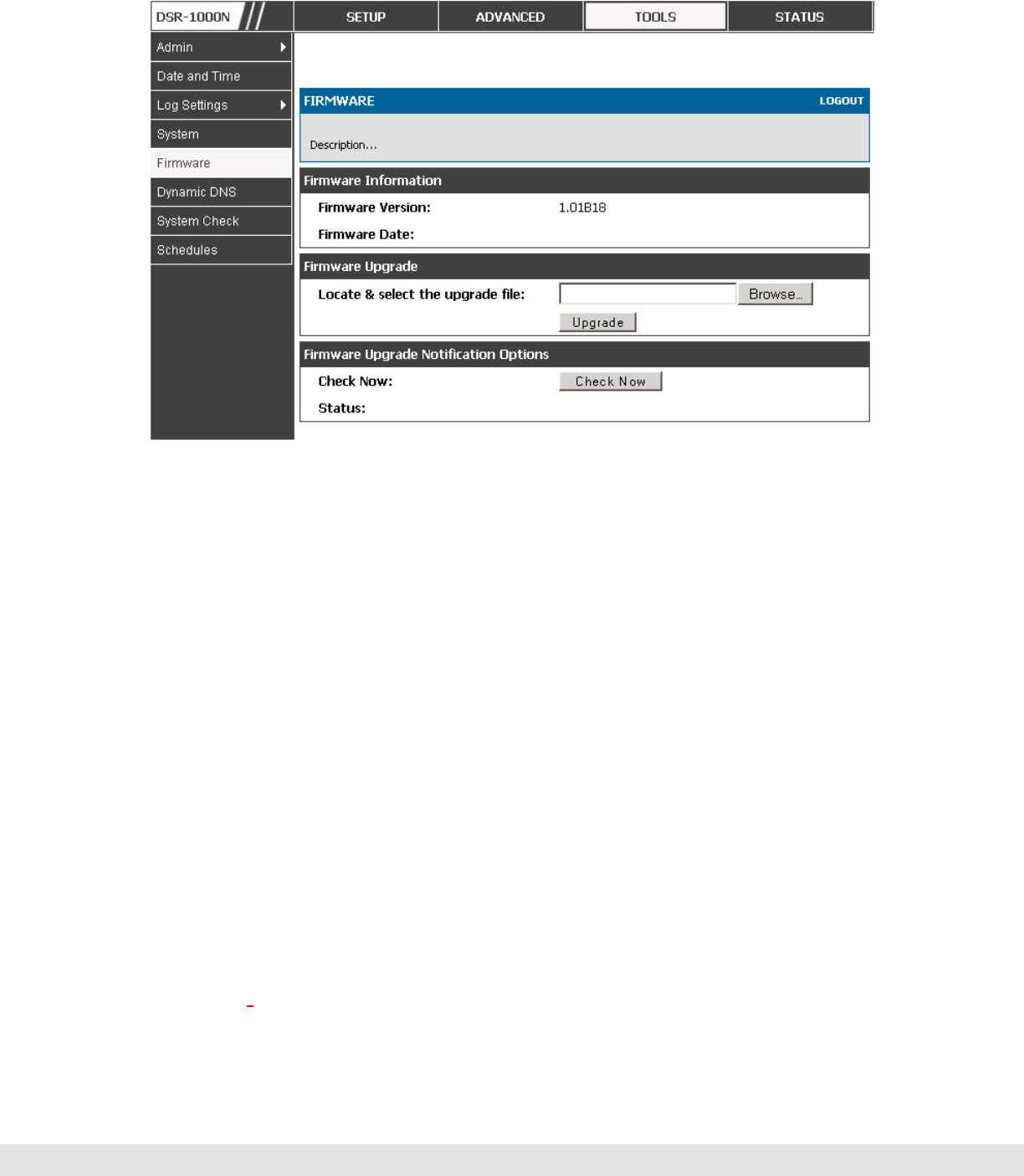
D-Link DSR Series Router
124
Figure 72: Firmware version information and upgrade option
This router also supports an automated notification to determine if a newer
firmware version is available for this router. By clicking the Check Now button
in the notification section, the router will check a D-Link server to see if a
newer firmware version for this router is available for download and update
the Status field below.
9.6 Dynamic DNS Setup
Tools > Dynamic DNS
Dynamic DNS (DDNS) is an Internet service that allows routers with varying
public IP addresses to be located using Internet domain names. To use
DDNS, you must setup an account with a DDNS provider such as
DynDNS.org, D-Link DDNS, or Oray.net.
Each configured WAN can have a different DDNS service if required. Once
configured, the router will update DDNS services changes in the WAN IP
address so that features that are dependent on accessing the router’s WAN
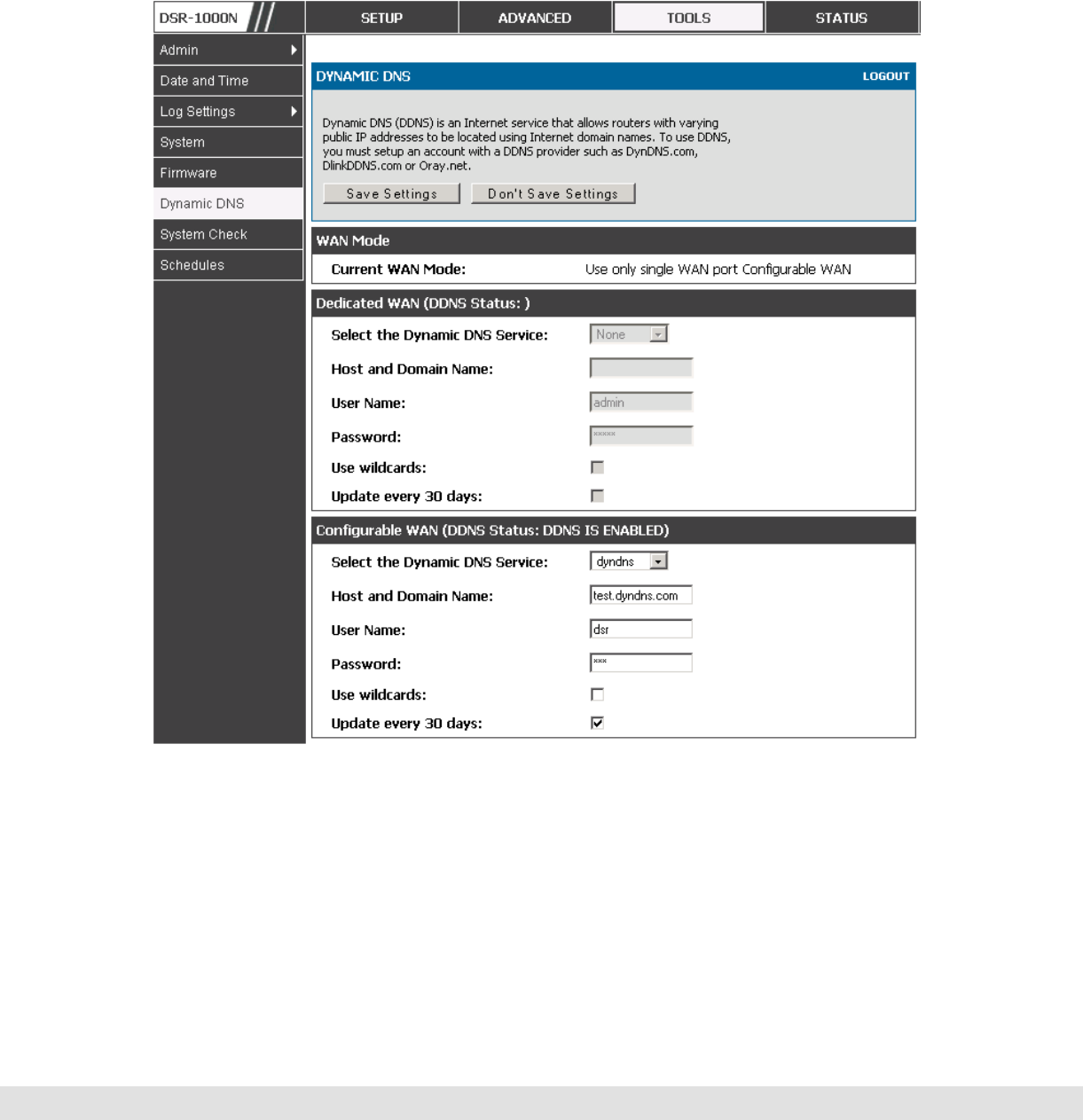
User Manual
125
via FQDN will be directed to the correct IP address. When you set up an
account with a DDNS service, the host and domain name, username,
password and wildcard support will be provided by the account provider.
Figure 73: Dynamic DNS configuration
9.7 Using Diagnostic Tools
Tools > System Check
The router has built in tools to allow an administrator to evaluate the
communication status and overall network health.
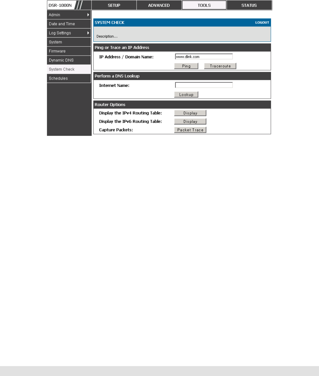
D-Link DSR Series Router
126
Figure 74: Router diagnostics tools available in the GUI
9.7.1 Ping
This utility can be used to test connectivity between this router and another
device on the network connected to this router. Enter an IP address and
click PING. The command output will appear indicating the ICMP echo
request status.
9.7.2 Trace Route
This utility will display all the routers present between the destination IP
address and this router. Up to 30 “hops” (intermediate routers) between this
router and the destination will be displayed.
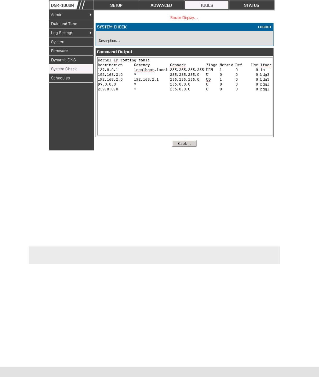
User Manual
127
Figure 75: Sample traceroute output
9.7.3 DNS Lookup
To retrieve the IP address of a Web, FTP, Mail or any other server on the
Internet, type the Internet Name in the text box and click Lookup. If the host
or domain entry exists, you will see a response with the IP address. A
message stating “Unknown Host” indicates that the specified Internet Name
does not exist.
This feature assumes there is internet access available on the WAN link(s).
9.7.4 Router Options
The static and dynamic routes configured on this router can be shown by
clicking Display for the corresponding routing table. Clicking the Packet
Trace button will allow the router to capture and display traffic through the
device between the LAN and WAN interface as well. This information is
often very useful in debugging traffic and routing issues.

D-Link DSR Series Router
128
10. Router Status and Statistics
10.1 System Overview
The Status page allows you to get a detailed overview of the system
configuration. The settings for the wired and wireless interfaces are displayed
in the Device Status page, and then the resulting hardware resource and
router usage details are summarized on the router’s Dashboard.
10.1.1 Device Status
Status > Device Info > Device Status
The Device Status page gives a summary of the router configuration settings
configured in the Setup and Advanced menus. The static hardware serial
number and current firmware version are presented in the General section.
The WAN and LAN interface information shown on this page are based on
the administrator configuration parameters. The radio band and channel
settings are presented below along with all configured and active APs that
are enabled on this router.
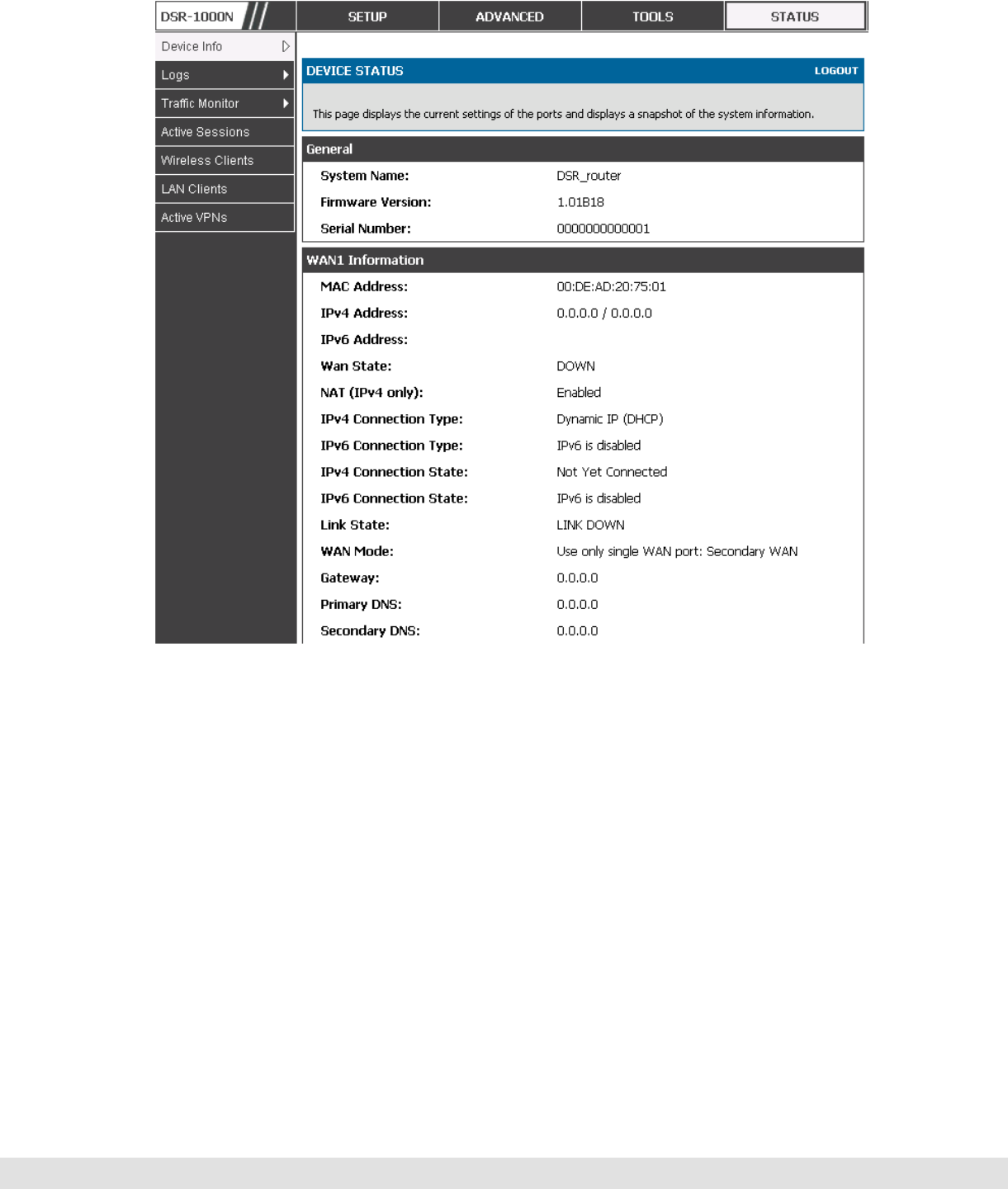
User Manual
129
Figure 76: Device Status display
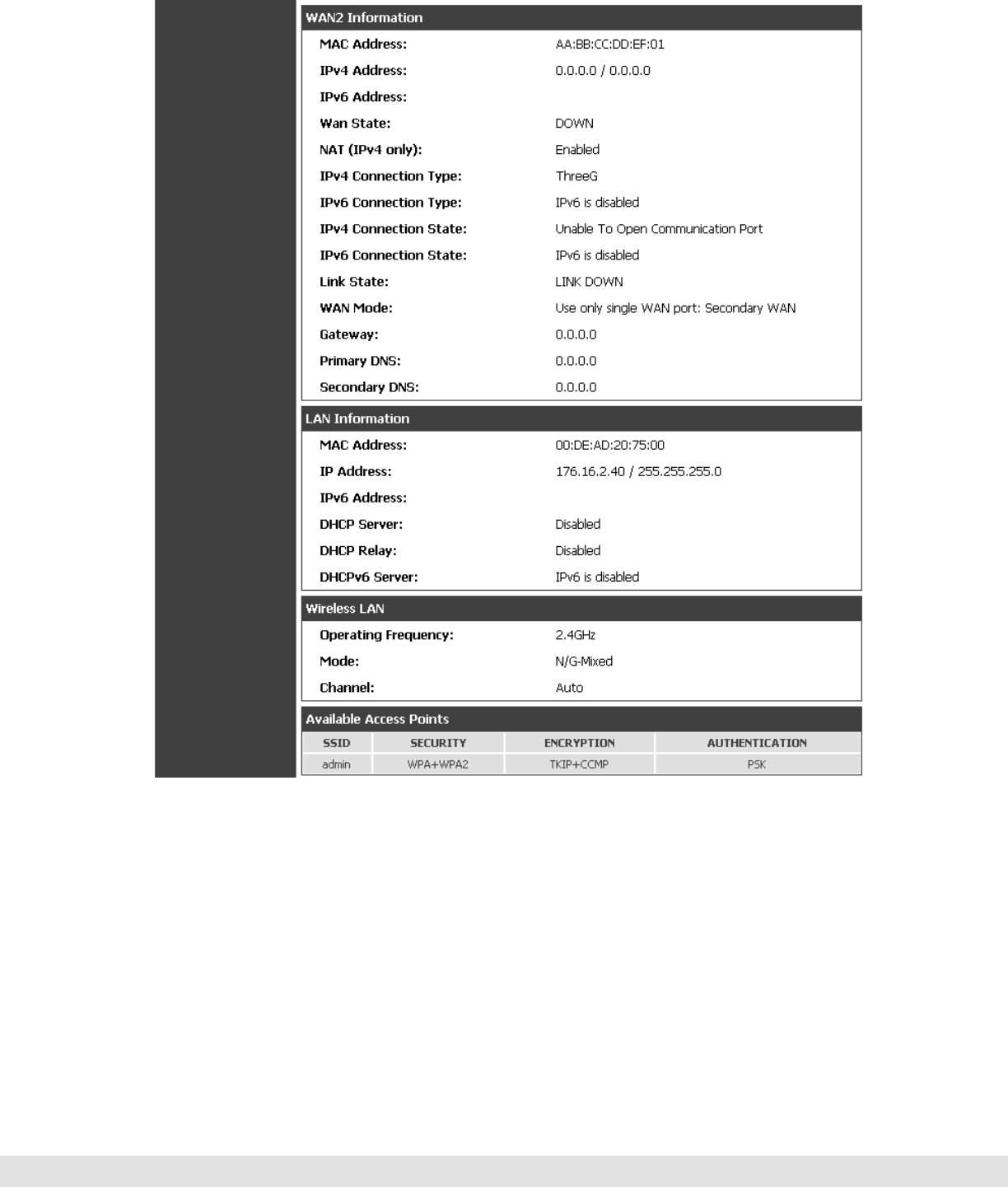
D-Link DSR Series Router
130
Figure 77: Device Status display (continued)
10.1.2 Resource Utilization
Status > Device Info > Dashboard
The Dashboard page presents hardware and usage statistics. The CPU and
Memory utilization is a function of the available hardware and current
configuration and traffic through the router. Interface statistics for the wired
connections (LAN, WAN1, WAN2/DMZ, VLANs) provide indication of packets
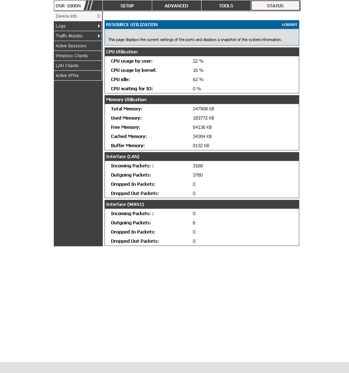
User Manual
131
through and packets dropped by the interface. Click refresh to have this
page retrieve the most current statistics.
Figure 78: Resource Utilization data
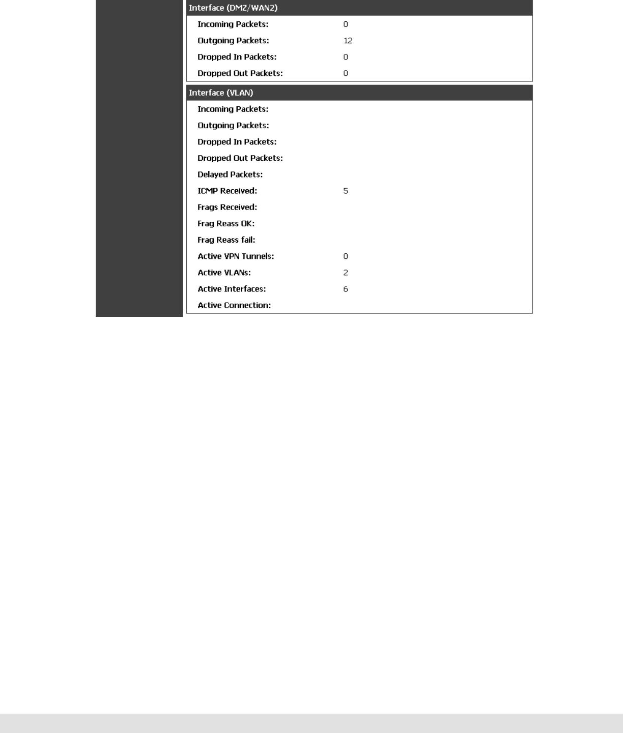
D-Link DSR Series Router
132
Figure 79: Resource Utilization data (continued)
10.2 Traffic Statistics
10.2.1 Wired Port Statistics
Status > Traffic Monitor > Device Statistics
Detailed transmit and receive statistics for each physical port are presented
here. Each interface (WAN1, WAN2/DMZ, LAN, and VLANs) have port
specific packet level information provided for review. Transmitted/received
packets, port collisions, and the cumulating bytes/sec for transmit/receive
directions are provided for each interface along with the port up time. If you
suspect issues with any of the wired ports, this table will help diagnose
uptime or transmit level issues with the port.
The statistics table has auto-refresh control which allows display of the most
current port level data at each page refresh. The default auto-refresh for
this page is 10 seconds.
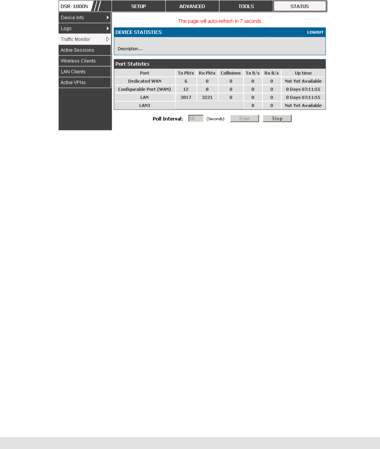
User Manual
133
Figure 80: Physical port statistics
10.2.2 Wireless Statistics
Status > Traffic Monitor > Wireless Statistics
The Wireless Statistics tab displays the incrementing traffic statistics for
each enabled access point. This page will give a snapshot of how much
traffic is being transmitted over each wireless link. If you suspect that a radio
or VAP may be down, the details on this page would confirm if traffic is being
sent and received through the VAP.
The clients connected to a particular AP can be viewed by using the Status
Button on the list of APs in the Setup > Wireless > Access Points page.
Traffic statistics are shown for that individual AP, as compared to the
summary stats for each AP on this Statistics page. The poll interval (the
refresh rate for the statistics) can be modified to view more frequent traffic
and collision statistics.
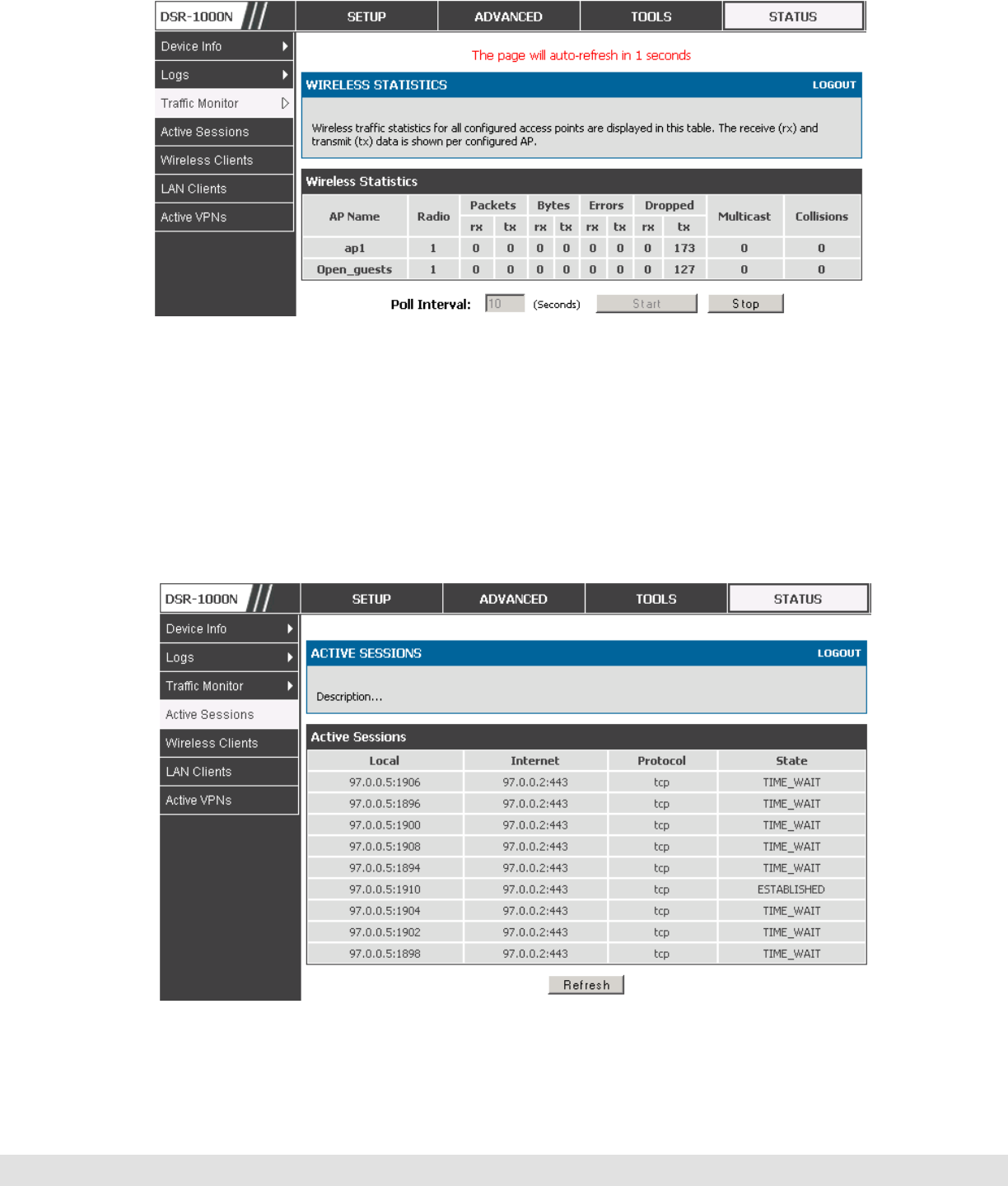
D-Link DSR Series Router
134
Figure 81: AP specific statistics
10.3 Active Connections
10.3.1 Sessions through the Router
Status > Active Sessions
This table lists the active internet sessions through the router’s firewall. The
session’s protocol, state, local and remote IP addresses are shown.
F
Figure 82: List of current Active Firewall Sessions
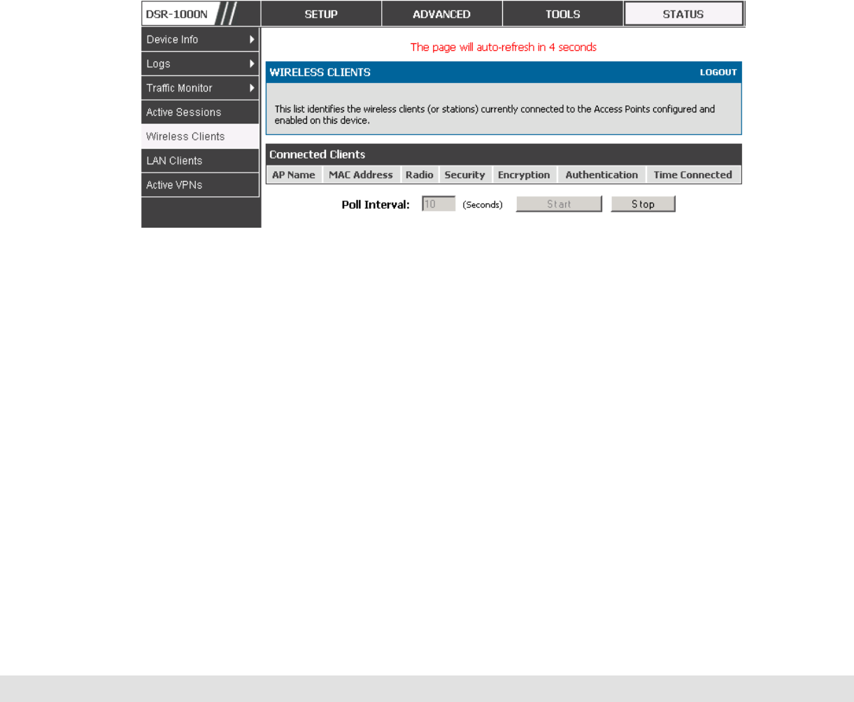
User Manual
135
10.3.2 Wireless Clients
Status > Wireless Clients
The clients connected to a particular AP can be viewed on this page.
Connected clients are sorted by the MAC address and indicate the security
parameters used by the wireless link, as well as the time connected to the
corresponding AP.
The statistics table has auto-refresh control which allows display of the most
current port level data at each page refresh. The default auto-refresh for
this page is 10 seconds.
Figure 83: List of connected 802.11 clients per AP
10.3.3 LAN Clients
Status > LAN Clients
The LAN clients to the router are identified by an ARP scan through the LAN
switch. The NetBios name (if available), IP address and MAC address of
discovered LAN hosts are displayed.
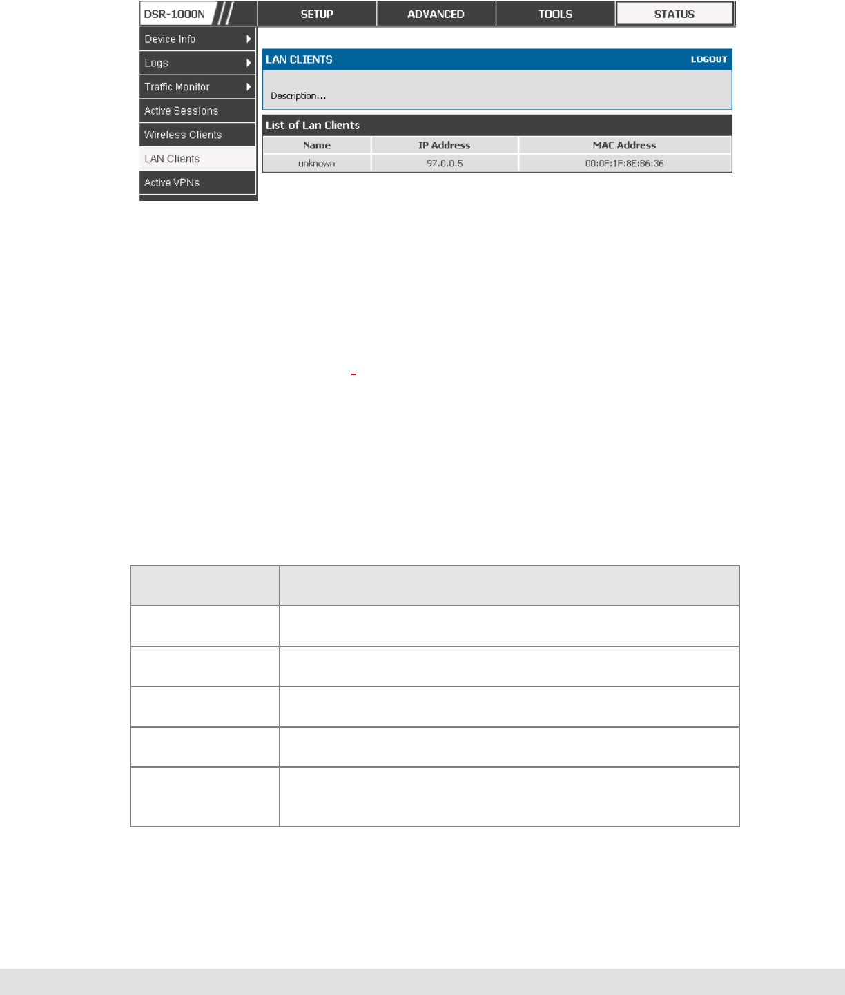
D-Link DSR Series Router
136
Figure 84: List of LAN hosts
10.3.4 Active VPN Tunnels
Status > Active VPNs
You can view and change the status (connect or drop) of the router’s IPSec
security associations. Here, the active IPSec SAs (security associations)
are listed along with the traffic details and tunnel state. The traffic is a
cumulative measure of transmitted/received packets since the tunnel was
established.
If a VPN policy state is “IPsec SA Not Established”, it can be enabled by
clicking the Connect button of the corresponding policy. The Active IPSec
SAs table displays a list of active IPSec SAs. Table fields are as follows.
Field Description
Policy Name IKE or VPN policy associated with this SA.
Endpoint IP address of the remote VPN gateway or client.
Tx (KB) Kilobytes of data transmitted over this SA.
Tx (Packets) Number of IP packets transmitted over this SA.
State Status of the SA for IKE policies: Not Connected or IPSec
SA Established.
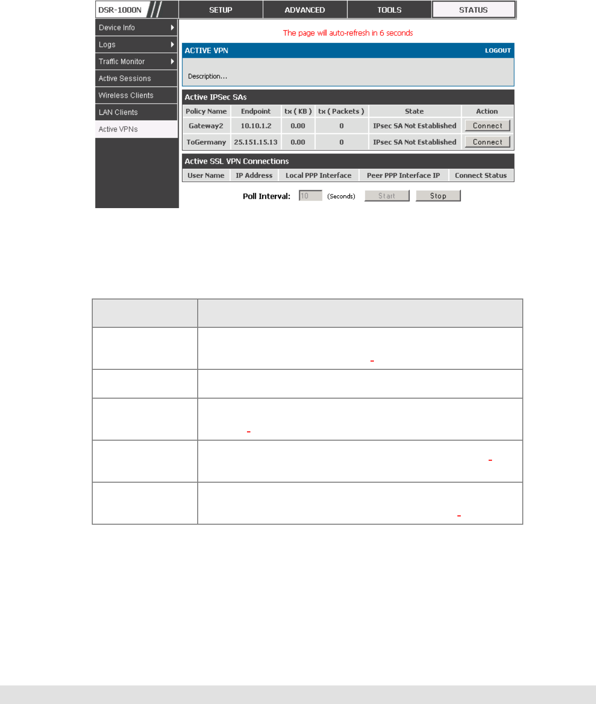
User Manual
137
Figure 85: List of current Active Firewall Sessions
All active SSL VPN connections, both for VPN tunnel and VPN Port
forwarding, are displayed on this page as well. Table fields are as follows.
Field Description
User Name The SSL VPN user that has an active tunnel or port
forwarding session to this router.
IP Address IP address of the remote VPN client.
Local PPP
Interface The interface (WAN1 or WAN2) through which the session
is active.
Peer PPP
Interface IP The assigned IP address of the virtual network adapter.
Connect Status Status of the SSL connection between this router and the
remote VPN client: Not Connected or Connected.

D-Link DSR Series Router
138
11. Trouble Shooting
11.1 Internet connection
Symptom: You cannot access the router’s web-configuration interface from a
PC on your LAN.
Recommended action:
1. Check the Ethernet connection between the PC and the router.
2. Ensure that your PC’s IP address is on the same subnet as the router. If you are
using the recommended addressing scheme, your PC’s address should be in the
range 192.168.10.2 to 192.168.10.254.
3. Check your PC’s IP address. If the PC cannot reach a DHCP server, some
versions of Windows and Mac OS generate and assign an IP address. These
auto-generated addresses are in the range 169.254.x.x. If your IP address is in
this range, check the connection from the PC to the firewall and reboot your PC.
4. If your router’s IP address has changed and you don’t know what it is, reset the
router configuration to factory defaults (this sets the firewall’s IP address to
192.168.10.1).
5. If you do not want to reset to factory default settings and lose your configuration,
reboot the router and use a packet sniffer (such as Ethereal™) to capture
packets sent during the reboot. Look at the Address Resolution Protocol (ARP)
packets to locate the router’s LAN interface address.
6. Launch your browser and ensure that Java, JavaScript, or ActiveX is enabled. If
you are using Internet Explorer, click Refresh to ensure that the Java applet is
loaded. Close the browser and launch it again.
7. Ensure that you are using the correct login information. The factory default login
name is admin and the password is password. Ensure that CAPS LOCK is off
when entering this information.
Symptom: Router does not save configuration changes.
Recommended action:

User Manual
139
1. When entering configuration settings, click Apply before moving to another menu
or tab; otherwise your changes are lost.
2. Click Refresh or Reload in the browser. Your changes may have been made, but
the browser may be caching the old configuration.
Symptom: Router cannot access the Internet.
Possible cause: If you use dynamic IP addresses, your router may not have
requested an IP address from the ISP.
Recommended action:
1. Launch your browser and go to an external site such as www.google.com.
2. Access the firewall’s configuration main menu at http://192.168.10.1.
3. Select Monitoring > Router Status.
4. Ensure that an IP address is shown for the WAN port. If 0.0.0.0 is shown, your
firewall has not obtained an IP address from your ISP. See the next symptom.
Symptom: Router cannot obtain an IP address from the ISP.
Recommended action:
1. Turn off power to the cable or DSL modem.
2. Turn off the router.
3. Wait 5 minutes, and then reapply power to the cable or DSL modem.
4. When the modem LEDs indicate that it has resynchronized with the ISP, reapply
power to the router. If the router still cannot obtain an ISP address, see the next
symptom.
Symptom: Router still cannot obtain an IP address from the ISP.
Recommended action:
1. Ask your ISP if it requires a login program — PPP over Ethernet (PPPoE) or
some other type of login.
2. If yes, verify that your configured login name and password are correct.

D-Link DSR Series Router
140
3. Ask your ISP if it checks for your PC's hostname.
4. If yes, select Network Configuration > WAN Settings > Ethernet ISP Settings and
set the account name to the PC hostname of your ISP account.
5. Ask your ISP if it allows only one Ethernet MAC address to connect to the
Internet, and therefore checks for your PC’s MAC address.
6. If yes, inform your ISP that you have bought a new network device, and ask them
to use the firewall’s MAC address.
7. Alternatively, select Network Configuration > WAN Settings > Ethernet ISP
Settings and configure your router to spoof your PC’s MAC address.
Symptom: Router can obtain an IP address, but PC is unable to load Internet
pages.
Recommended action:
1. Ask your ISP for the addresses of its designated Domain Name System (DNS)
servers. Configure your PC to recognize those addresses. For details, see your
operating system documentation.
2. On your PC, configure the router to be its TCP/IP gateway.
11.2 Date and time
Symptom: Date shown is January 1, 1970.
Possible cause: The router has not yet successfully reached a network time
server (NTS).
Recommended action:
1. If you have just configured the router, wait at least 5 minutes, select
Administration > Time Zone, and recheck the date and time.
2. Verify your Internet access settings.
Symptom: Time is off by one hour.
Possible cause: The router does not automatically adjust for Daylight
Savings Time.

User Manual
141
Recommended action:
1. Select Administration > Time Zone and view the current date and time settings.
2. Click to check or uncheck “Automatically adjust for Daylight Savings Time”, then
click Apply.
11.3 Pinging to Test LAN Connectivity
Most TCP/IP terminal devices and firewalls contain a ping utility that sends an
ICMP echo-request packet to the designated device. The device responds
with an echo reply. Troubleshooting a TCP/IP network is made very easy by
using the ping utility in your PC or workstation.
11.3.1 Testing the LAN path from your PC to your router
1. From the PC’s Windows toolbar, select Start > Run.
2. Type ping <IP_address> where <IP_address> is the router’s IP address.
Example: ping 192.168.10.1.
3. Click OK.
4. Observe the display:
If the path is working, you see this message sequence:
Pinging <IP address> with 32 bytes of data
Reply from <IP address>: bytes=32 time=NN ms TTL=xxx
If the path is not working, you see this message sequence:
Pinging <IP address> with 32 bytes of data
Request timed out
5. If the path is not working, Test the physical connections between PC and router
If the LAN port LED is off, go to the “LED displays” section on page B-1 and
follow instructions for “LAN or Internet port LEDs are not lit.”
Verify that the corresponding link LEDs are lit for your network interface card
and for any hub ports that are connected to your workstation and firewall.

D-Link DSR Series Router
142
6. If the path is still not up, test the network configuration:
Verify that the Ethernet card driver software and TCP/IP software are installed
and configured on the PC.
Verify that the IP address for the router and PC are correct and on the same
subnet.
11.3.2 Testing the LAN path from your PC to a remote device
1. From the PC’s Windows toolbar, select Start > Run.
2. Type ping -n 10 <IP_address> where -n 10 specifies a maximum of 10 tries and
<IP address> is the IP address of a remote device such as your ISP’s DNS
server. Example: ping -n 10 10.1.1.1.
3. Click OK and then observe the display (see the previous procedure).
4. If the path is not working, do the following:
Check that the PC has the IP address of your firewall listed as the default
gateway. (If the IP configuration of your PC is assigned by DHCP, this
information is not visible in your PC’s Network Control Panel.)
Verify that the network (subnet) address of your PC is different from the network
address of the remote device.
Verify that the cable or DSL modem is connected and functioning.
Ask your ISP if it assigned a hostname to your PC.
If yes, select Network Configuration > WAN Settings > Ethernet ISP Settings
and enter that hostname as the ISP account name.
Ask your ISP if it rejects the Ethernet MAC addresses of all but one of your
PCs.
Many broadband ISPs restrict access by allowing traffic from the MAC
address of only your broadband modem; but some ISPs additionally restrict
access to the MAC address of just a single PC connected to that modem. If

User Manual
143
this is the case, configure your firewall to clone or spoof the MAC address
from the authorized PC.
11.4 Restoring factory-default configuration settings
To restore factory-default configuration settings, do either of the following:
1. Do you know the account password and IP address?
If yes, select Administration > Settings Backup & Upgrade and click default.
If no, do the following:
On the rear panel of the router, press and hold the Reset button about 10
seconds, until the test LED lights and then blinks.
Release the button and wait for the router to reboot.
2. If the router does not restart automatically; manually restart it to make the default
settings effective.
3. After a restore to factory defaults —whether initiated from the configuration
interface or the Reset button — the following settings apply:
LAN IP address: 192.168.10.1
Username: admin
Password: password
DHCP server on LAN: enabled
WAN port configuration: Get configuration via DHCP

145
12. Credits
Microsoft, Windows are registered trademarks of Microsoft Corp.
Linux is a registered trademark of Linus Torvalds.
UNIX is a registered trademark of The Open Group.

D-Link DSR Series Router
146
Appendix A. Glossary
ARP Address Resolution Protocol. Broadcast protocol for mapping IP
addresses to MAC addresses.
CHAP Challenge-Handshake Authentication Protocol. Protocol for
authenticating users to an ISP.
DDNS Dynamic DNS. System for updating domain names in real time.
Allows a domain name to be assigned to a device with a dynamic IP
address.
DHCP Dynamic Host Configuration Protocol. Protocol for allocating IP
addresses dynamically so that addresses can be reused when hosts
no longer need them.
DNS Domain Name System. Mechanism for translating H.323 IDs, URLs,
or e-mail IDs into IP addresses. Also used to assist in locating
remote gatekeepers and to map IP addresses to hostnames of
administrative domains.
FQDN Fully qualified domain name. Complete domain name, including the
host portion. Example: serverA.companyA.com.
FTP File Transfer Protocol. Protocol for transferring files between network
nodes.
HTTP Hypertext Transfer Protocol. Protocol used by web browsers and
web servers to transfer files.
IKE Internet Key Exchange. Mode for securely exchanging encryption
keys in ISAKMP as part of building a VPN tunnel.
IPSec IP security. Suite of protocols for securing VPN tunnels by
authenticating or encrypting IP packets in a data stream. IPSec
operates in either transport mode (encrypts payload but not packet
headers) or tunnel mode (encrypts both payload and packet
headers).
ISAKMP Internet Key Exchange Security Protocol. Protocol for establishing
security associations and cryptographic keys on the Internet.
ISP Internet service provider.

User Manual
147
MAC
Address Media-access-control address. Unique physical-address identifier
attached to a network adapter.
MTU Maximum transmission unit. Size, in bytes, of the largest packet that
can be passed on. The MTU for Ethernet is a 1500-byte packet.
NAT Network Address Translation. Process of rewriting IP addresses as a
packet passes through a router or firewall. NAT enables multiple
hosts on a LAN to access the Internet using the single public IP
address of the LAN’s gateway router.
NetBIOS Microsoft Windows protocol for file sharing, printer sharing,
messaging, authentication, and name resolution.
NTP Network Time Protocol. Protocol for synchronizing a router to a
single clock on the network, known as the clock master.
PAP Password Authentication Protocol. Protocol for authenticating users
to a remote access server or ISP.
PPPoE Point-to-Point Protocol over Ethernet. Protocol for connecting a
network of hosts to an ISP without the ISP having to manage the
allocation of IP addresses.
PPTP Point-to-Point Tunneling Protocol. Protocol for creation of VPNs for
the secure transfer of data from remote clients to private servers over
the Internet.
RADIUS Remote Authentication Dial-In User Service. Protocol for remote user
authentication and accounting. Provides centralized management of
usernames and passwords.
RSA Rivest-Shamir-Adleman. Public key encryption algorithm.
TCP Transmission Control Protocol. Protocol for transmitting data over the
Internet with guaranteed reliability and in-order delivery.
UDP User Data Protocol. Protocol for transmitting data over the Internet
quickly but with no guarantee of reliability or in-order delivery.
VPN Virtual private network. Network that enables IP traffic to travel
securely over a public TCP/IP network by encrypting all traffic from
one network to another. Uses tunneling to encrypt all information at
the IP level.

D-Link DSR Series Router
148
WINS Windows Internet Name Service. Service for name resolution. Allows
clients on different IP subnets to dynamically resolve addresses,
register themselves, and browse the network without sending
broadcasts.
XAUTH IKE Extended Authentication. Method, based on the IKE protocol, for
authenticating not just devices (which IKE authenticates) but also
users. User authentication is performed after device authentication
and before IPSec negotiation.

149
Appendix B. Factory Default Settings
Feature Description Default Setting
Device login User login URL http://192.168.10.1
User name (case sensitive) admin
Login password (case sensitive) admin
Internet
Connection WAN MAC address Use default address
WAN MTU size 1500
Port speed Autosense
Local area
network (LAN) IP address 192.168.10.1
IPv4 subnet mask 255.255.255.0
RIP direction None
RIP version Disabled
RIP authentication Disabled
DHCP server Enabled
DHCP starting IP address 192.168.10.2
DHCP ending IP address 192.168.10.100
Time zone GMT
Time zone adjusted for Daylight Saving
Time Disabled
SNMP Disabled
Remote management Disabled

D-Link DSR Series Router
150
Firewall Inbound communications from the
Internet Disabled (except traffic
on port 80, the HTTP
port)
Outbound communications to the
Internet Enabled (all)
Source MAC filtering Disabled
Stealth mode Enabled

User Manual
151
Appendix C. Standard Services Available for Port Forwarding &
Firewall Configuration
ANY
AIM
BGP
BOOTP_CLIENT
BOOTP_SERVER
CU-SEEME:UDP
CU-SEEME:TCP
DNS:UDP
DNS:TCP
FINGER
FTP
HTTP
HTTPS
ICMP-TYPE-3
ICMP-TYPE-4
ICMP-TYPE-5
ICMP-TYPE-6
ICMP-TYPE-7
ICMP-TYPE-8
ICMP-TYPE-9
ICMP-TYPE-10
ICMP-TYPE-11
ICMP-TYPE-13
ICQ
IMAP2
IMAP3
IRC
NEWS
NFS
NNTP
PING
POP3
PPTP
RCMD
REAL-AUDIO
REXEC
RLOGIN
RTELNET
RTSP:TCP
RTSP:UDP
SFTP
SMTP
SNMP:TCP
SNMP:UDP
SNMP-TRAPS:TCP
SNMP-TRAPS:UDP
SQL-NET
SSH:TCP
SSH:UDP
STRMWORKS
TACACS
TELNET
TFTP
VDOLIVE
FCC Radiation Exposure Statement
This equipment complies with FCC RF radiation exposure limits set forth for an uncontrolled environment. This equipment
should be installed and operated with a minimum distance of 20 centimeters between the radiator and your body.
This device complies with Part 15 of the FCC Rules. Operation is subject to the following two conditions:
1) This device may not cause harmful interference, and
2) This device must accept any interference received, including interference that may cause undesired operation.
This transmitter must not be co-located or operating in conjunction with any other antenna or transmitter.
The antennas used for this transmitter must be installed to provide a spectrum distance of at least 20cm from all persons
and must not be co-located or operating in conjunction with any other antenna or transmitter.
This transmitter is restricted to indoor use in the 5150MHz to 5250MHz frequency range.
Non-modification Statement
Use only the integral antenna supplied by the manufacturer when operating this device. Unauthorized antennas,
modifications, or attachments could damage the TI Navigator access point and violate FCC regulations. Any changes
or modifications not expressly approved by the party responsible for compliance could void the user's authority to
operate this equipment.
Federal Communications Commission (FCC) Compliance Notice: Radio Frequency Notice
This equipment has been tested and found to comply with the limits for a Class B digital device, pursuant to part 15 of
the FCC Rules. These limits are designed to provide reasonable protection against harmful interference in a residential
installation. This equipment generates, uses, and can radiate radio frequency energy and, if not installed and used in
accordance with the instructions, may cause harmful interference to radio communications. However, there is no
guarantee that interference will not occur in a particular installation. If this equipment does cause harmful interference to
radio or television reception, which can be determined by turning the equipment off and on, the user is encouraged to try
to correct the interference by one or more of the following measures:
• Reorient or relocate the receiving antenna.
• Increase the separation between the equipment and receiver.
• Connect the equipment into an outlet on a circuit different from that to which the receiver is connected.
• Consult the dealer or an experienced radio/TV technician for help.
Canadian Department of Communications Industry Canada (IC) Notice
This Class B digital apparatus complies with Canadian ICES-003 and RSS-210. Cet appareil numérique de la classe B
est conforme à la norme NMB-003 et CNR-210 du Canada.
ndustry Canada Statement
This device complies with RSS-210 of the Industry Canada Rules. Operation is subject to the following two conditions:
(1) This device may not cause harmful interference, and
(2) this device must accept any interference received, including interference that may cause undesired operation.
IMPORTANT NOTE: Radiation Exposure Statement
This equipment complies with IC radiation exposure limits set forth for an uncontrolled
environment. End users must follow the specific operating instructions for satisfying RF
exposure compliance. To maintain compliance with IC RF exposure compliance requirements,
please follow operation instruction as documented in this manual.
This transmitter is restricted to indoor use in the 5150MHz to 5250MHz frequency range.

Europe – EU Declaration of Conformity
This device complies with the essential requirements of the R&TTE Directive 1999/5/EC. The following
test methods have been applied in order to prove presumption of conformity with the essential requirements
of the R&TTE Directive 1999/5/EC:
- EN 60950-1: 2006+A11:2009
Safety of information technology equipment
- EN 300 328 V1.7.1 (2006-10)
Electromagnetic compatibility and Radio spectrum Matters (ERM); Wideband transmission systems; Data
transmission equipment operating in the 2,4 GHz ISM band and using wide band modulation techniques;
Harmonized EN covering essential requirements under article 3.2 of the R&TTE Directive
- EN 301 893-1 V1.5.1 (2008-12)
Broadband Radio Access Networks (BRAN); 5 GHz high performance RLAN; Harmonized EN covering essential
requirements of article 3.2 of the R&TTE Directive
- EN 301 489-17 V1.3.2 (2008-04) and EN 301 489-1 V1.8.1 (2008-04)
Electromagnetic compatibility and Radio spectrum Matters (ERM); Electro Magnetic Compatibility (EMC)
standard for radio equipment and services; Part 17: Specific conditions for 2,4 GHz wideband transmission
systems and 5 GHz high performance RLAN equipment
This device is a 2.4 GHz wideband transmission system (transceiver), intended for use in all EU member
states and EFTA countries under the following conditions and/or with the following restrictions:
- In Italy the end-user should apply for a license at the national spectrum authorities in order to obtain authorization to use
the device for setting up outdoor radio links and/or for supplying public access to telecommunications and/or network
services.
- This device may not be used for setting up outdoor radio links in France and in some areas the RF output
power may be limited to 10 mW EIRP in the frequency range of 2454 – 2483.5 MHz. For detailed information the
enduser should contact the national spectrum authority in France.
This device is a 5 GHz wideband transmission system (transceiver), intended for use in all EU member
states and EFTA countries under the following conditions and/or with the following restrictions:
- This device may only be used indoors in the frequency bands 5150 – 5250 MHz.
- In France and Luxembourg a limited implementation of the frequency bands 5150 – 5250 MHz and 5250 – 5350
MHz. In Luxermbourg it is not allowed to make use of the frequency band 5470 – 5725 MHz. End-users are
encouraged to contact the national spectrum authorities in France and Luxembourg in order to obtain the latest
information about any restrictions in the 5 GHz frequency band(s).
Česky
[Czech]
[D-Link Corporation] tímto prohlašuje, že tento [DSR-1000N] je ve shodě se základními
požadavky a dalšími příslušnými ustanoveními směrnice 1999/5/ES.
Dansk
[Danish]
Undertegnede [D-Link Corporation] erklæ rer herved, at følgende udstyr [DSR-1000N]
overholder de væ sentlige krav og øvrige relevante krav i direktiv 1999/5/EF.
Deutsch
[German]
Hiermit erklärt [D-Link Corporation], dass sich das Gerät [DSR-1000N] in Ü bereinstimmung mit
den grundlegenden Anforderungen und den übrigen einschlägigen Bestimmungen der Richtlinie
1999/5/EG befindet.
Eesti
[Estonian]
Käesolevaga kinnitab [D-Link Corporation] seadme [DSR-1000N] vastavust direktiivi 1999/5/EÜ
põhinõuetele ja nimetatud direktiivist tulenevatele teistele asjakohastele sätetele.
English
Hereby, [D-Link Corporation], declares that this [DSR-1000N] is in compliance with the essential
requirements and other relevant provisions of Directive 1999/5/EC.
Español
[Spanish]
Por medio de la presente [D-Link Corporation] declara que el [DSR-1000N] cumple con los
requisitos esenciales y cualesquiera otras disposiciones aplicables o exigibles de la Directiva
1999/5/CE.
Ελληνική
[Greek]
ΜΕ ΣΗΝ ΠΑΡΟΤΑ [D-Link Corporation] ΔΗΛΩΝΕΙ ΟΣΙ [DSR-1000N] ΤΜΜΟΡΦΩΝΕΣΑΙ
ΠΡΟ ΣΙ ΟΤΙΩΔΕΙ ΑΠΑΙΣΗΕΙ ΚΑΙ ΣΙ ΛΟΙΠΕ ΥΕΣΙΚΕ ΔΙΑΣΑΞΕΙ ΣΗ ΟΔΗΓΙΑ
1999/5/ΕΚ.
Français
[French]
Par la présente [D-Link Corporation] déclare que l'appareil [DSR-1000N] est conforme aux
exigences essentielles et aux autres dispositions pertinentes de la directive 1999/5/CE.
Italiano
[Italian]
Con la presente [D-Link Corporation] dichiara che questo [DSR-1000N] è conforme ai requisiti
essenziali ed alle altre disposizioni pertinenti stabilite dalla direttiva 1999/5/CE.
Latviski
[Latvian]
Ar šo [D-Link Corporation] deklarē, ka [DSR-1000N] atbilst Direktīvas 1999/5/EK būtiskajām
prasībām un citiem ar to saistītajiem noteikumiem.
Lietuvių
[Lithuanian]
Šiuo [D-Link Corporation] deklaruoja, kad šis [DSR-1000N] atitinka esminius reikalavimus ir
kitas 1999/5/EB Direktyvos nuostatas.
Nederlands
[Dutch]
Hierbij verklaart [D-Link Corporation] dat het toestel [DSR-1000N] in overeenstemming is met
de essentiële eisen en de andere relevante bepalingen van richtlijn 1999/5/EG.
Malti
[Maltese]
Hawnhekk, [D-Link Corporation], jiddikjara li dan [DSR-1000N] jikkonforma mal-ħtiġijiet
essenzjali u ma provvedimenti oħrajn relevanti li hemm fid-Dirrettiva 1999/5/EC.
Magyar
[Hungarian]
Alulírott, [D-Link Corporation] nyilatkozom, hogy a [DSR-1000N] megfelel a vonatkozó alapvetõ
követelményeknek és az 1999/5/EC irányelv egyéb elõírásainak.
Polski
[Polish]
Niniejszym [D-Link Corporation] oświadcza, że [DSR-1000N] jest zgodny z zasadniczymi
wymogami oraz pozostałymi stosownymi postanowieniami Dyrektywy 1999/5/EC.

Português
[Portuguese]
[D-Link Corporation] declara que este [DSR-1000N]está conforme com os requisitos essenciais
e outras disposições da Directiva 1999/5/CE.
Slovensko
[Slovenian]
[D-Link Corporation] izjavlja, da je ta [DSR-1000N] v skladu z bistvenimi zahtevami in ostalimi
relevantnimi določili direktive 1999/5/ES.
Slovensky
[Slovak]
[D-Link Corporation] týmto vyhlasuje, že [DSR-1000N] spĺňa základné požiadavky a všetky
príslušné ustanovenia Smernice 1999/5/ES.
Suomi
[Finnish]
[D-Link Corporation] vakuuttaa täten että [DSR-1000N] tyyppinen laite on direktiivin 1999/5/EY
oleellisten vaatimusten ja sitä koskevien direktiivin muiden ehtojen mukainen.
Svenska
[Swedish]
Härmed intygar [D-Link Corporation] att denna [DSR-1000N] står I överensstämmelse med de
väsentliga egenskapskrav och övriga relevanta bestämmelser som framgår av direktiv
1999/5/EG.