D Link SR250NB1 Wireless N Service Router User Manual 13
D Link Corporation Wireless N Service Router 13
UserManual.wiki
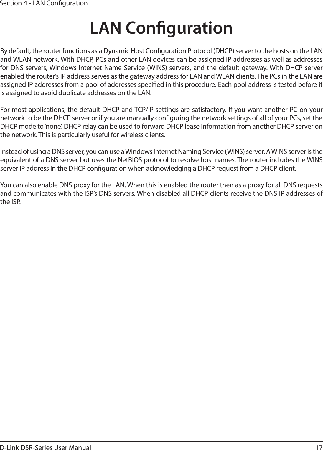
>
D Link
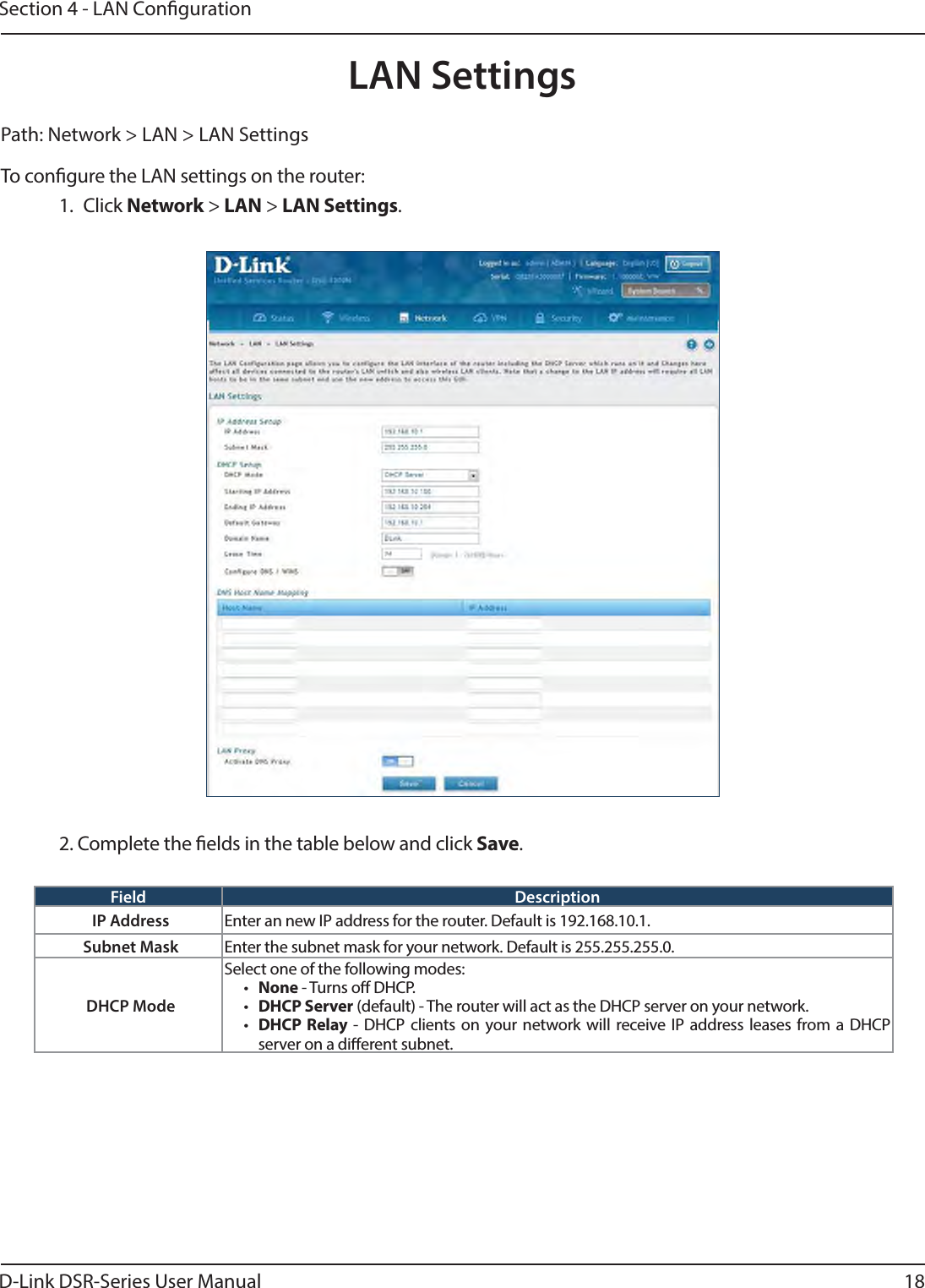
>
SR250NB1 User Manual
>
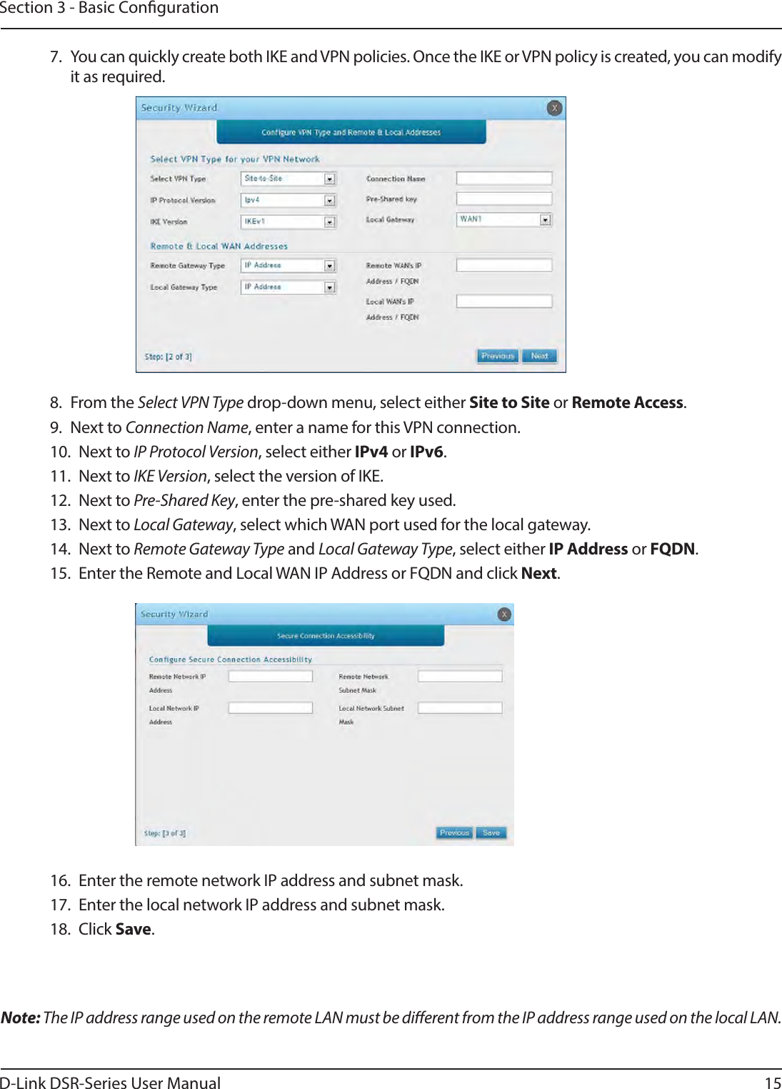
User Manual-1
Contents
1.
User Manual-1
2.
User Manual-2
User Manual-1
Navigation menu
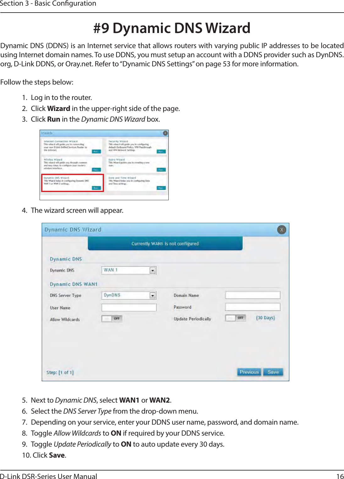
Upload a User Manual
Namespaces
Wiki Guide
HTML
PDF
Info
Views
User Manual
Discussion / Help
Navigation

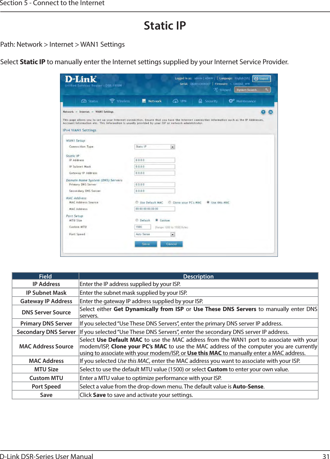
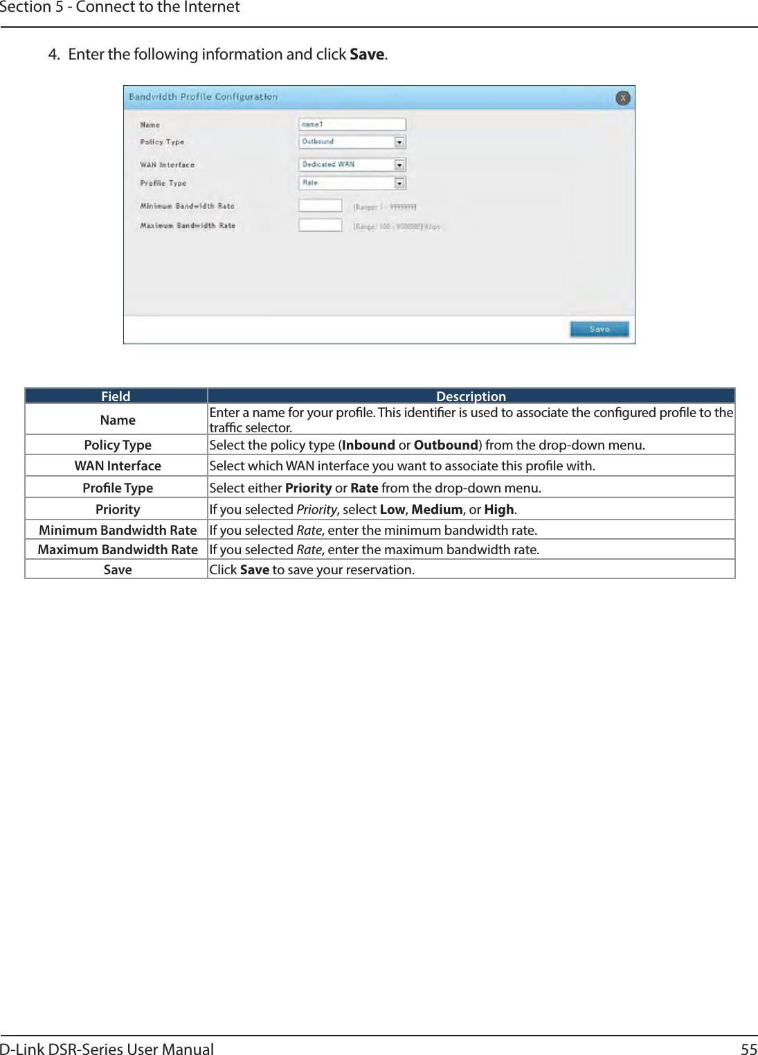
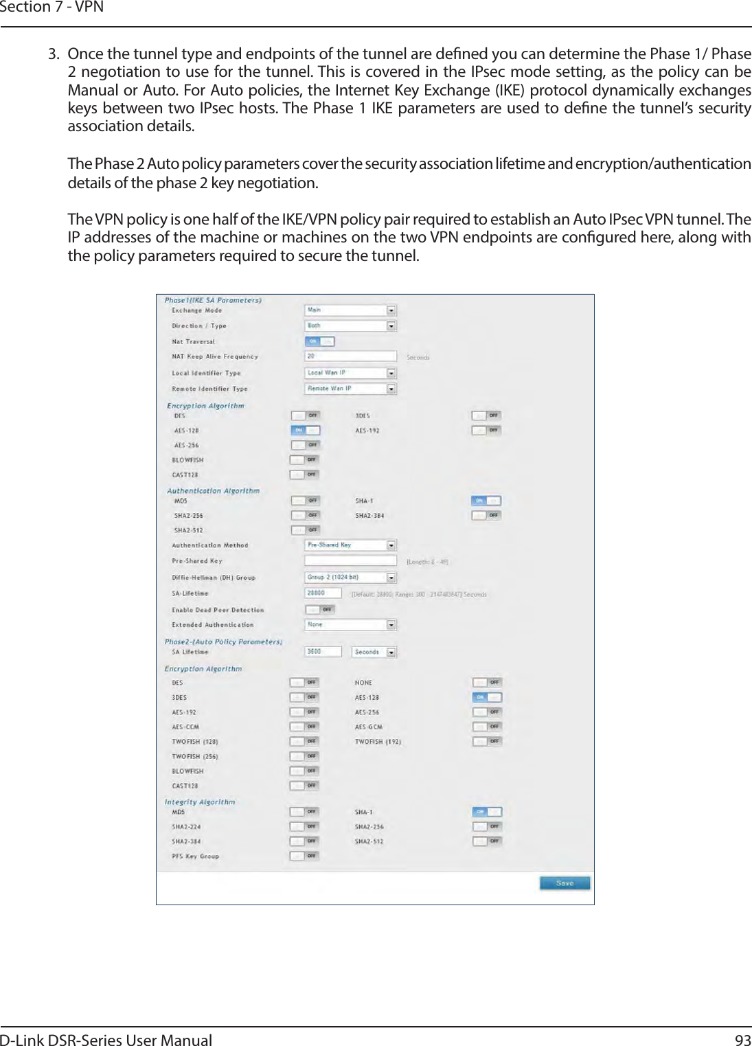
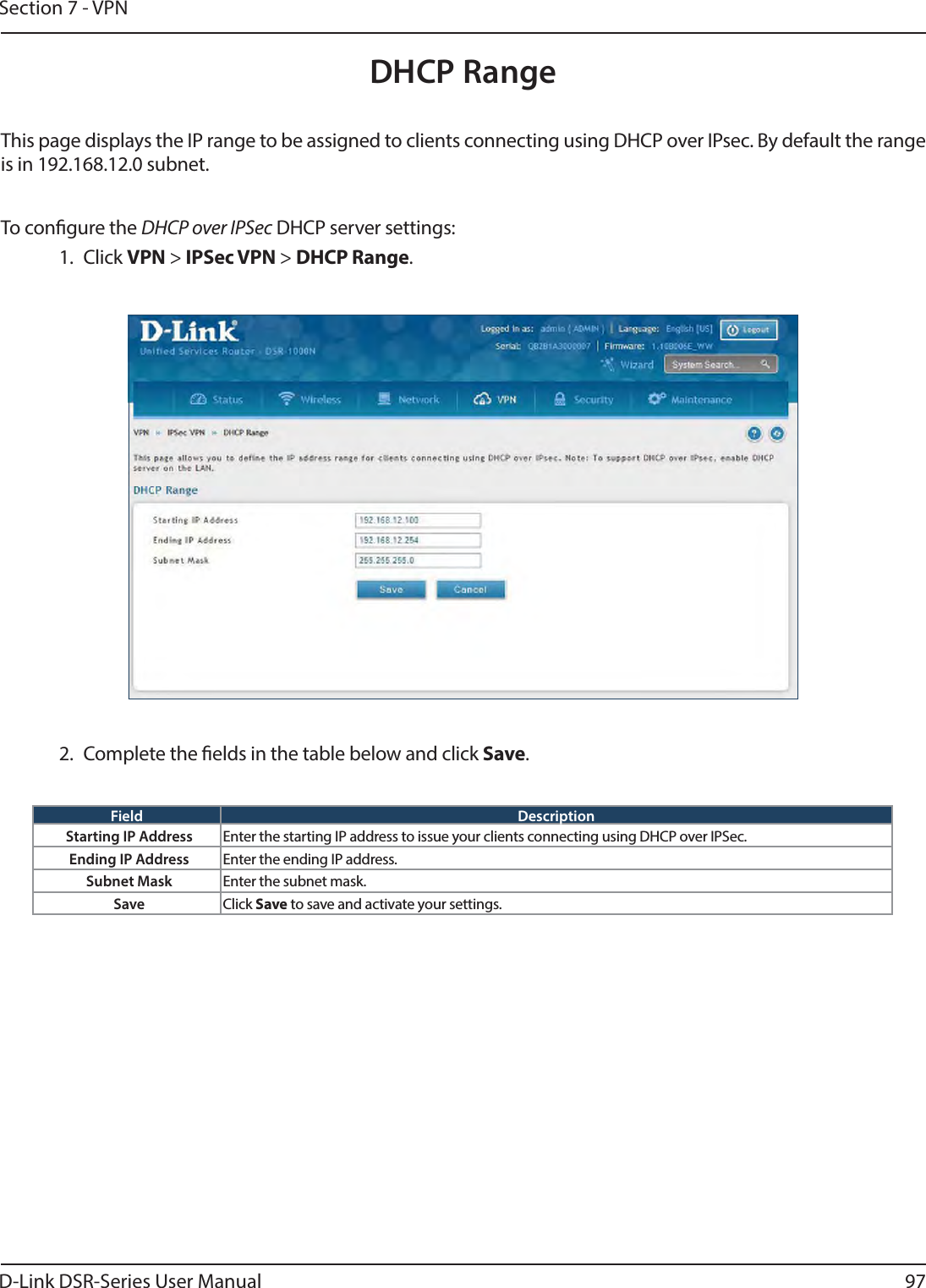
![D-Link DSR-Series User Manual 92Section 7 - VPNField DescriptionPolicy Name Enter a unique name for the VPN Policy. This name is not an identier for the remote WAN/client.Policy TypeSelect either Manual or Auto. • Manual: All settings (including the keys) for the VPN tunnel are manually input for each end point. No third-party server or organization is involved.• Auto: Some parameters for the VPN tunnel are generated automatically. This requires using the IKE (Internet Key Exchange) protocol to perform negotiations between the two VPN Endpoints.IP Protocol Version Select either IPv4 or IPv6.IKE Version Select the version of IKE.IPSec ModeSelect either Tunnel or Transport. IPsec tunnel mode is useful for protecting trac between dierent networks, when trac must pass through an intermediate, untrusted network. Tunnel mode is primarily used for interoperability with gateways, or end-systems that do not support L2TP/IPsec or PPTP connections. Transport mode is the default mode for IPsec, and it is used for end-to-end communications (for example, for communications between a client and a server).Select Local Gateway In the event that two WAN ports are congured to connect to your ISP, select the gateway that will be used as the local endpoint for this IPsec tunnel.Remote Endpoint Select the type of identier that you want to provide for the router at the remote endpoint (either IP Address or FQDN [Fully Qualied Domain Name])IP Address/FQDN Enter the identier for the router.Enable Mode Cong Toggle to ON to enable. Mode Cong is similar to DHCP and is used to assign IP addresses to the remote VPN clients.Enable NetBIOS Toggle to ON to allow NetBIOS broadcasts to travel over the VPN tunnelEnable RollOver Toggle to ON to enable VPN rollover. You must have the WAN Mode set to Rollover.Protocol Select a protocol from the drop-down menu.Enable DHCP Toggle to ON to allow VPN clients that are connected to your router over IPsec to receive an assigned IP using DHCP.Local IP/Remote IPSelect the type of identier that you want to provide for the endpoint:• Any: Species that the policy is for trac from the given end point (local or remote). Note that selecting Any for both local and remote end points is not valid.• Single: Limits the policy to one host. Enter the IP address of the host that will be part of the VPN.• Range: Allows computers within an IP address range to connect to the VPN. Enter the Start IP Address and End IP Address in the provided elds.• Subnet: Allows an entire subnet to connect to the VPN. Enter the network address and subnet mask in the provided elds.Enable Keepalive Toggle to ON to periodically send ping packets to the host on the peer side of the network to keep the tunnel alive.](https://usermanual.wiki/D-Link/SR250NB1.User-Manual-1/User-Guide-2549377-Page-105.png)