D Link SR250NB1 Wireless N Service Router User Manual 13
D Link Corporation Wireless N Service Router 13
D Link >
Contents
- 1. User Manual-1
- 2. User Manual-2
User Manual-1

Unied Services Router
User Manual
DSR-150/150N/250/250N/500/500N/1000/1000N
Version 2.01 | November 17, 2014
Wireless N Service Router
DSR-250NB1

D-Link DSR-Series User Manual i
The information in this document is subject to change without notice. The manufacturer makes no representations
or warranties with respect to the contents hereof and specically disclaim any implied warranties of merchantability
or tness for any particular purpose. The manufacturer reserves the right to revise this publication and to make
changes from time to time in the content hereof without obligation of the manufacturer to notify any person of
such revision or changes.
Manual Revisions
Revision Date Description
2.00 July 31, 2014 • DSR Products with rmware version 2.00
2.01 November 17, 2014 • add License Update section
Trademarks/Copyright Notice
D-Link and the D-Link logo are trademarks or registered trademarks of D-Link Corporation or its subsidiaries in
the United States or other countries. All other company or product names mentioned herein are trademarks or
registered trademarks of their respective companies.
© 2014 D-Link Corporation, All Rights Reserved
This publication, including all photographs, illustrations and software, is protected under international copyright
laws, with all rights reserved. Neither this manual, nor any of the material contained herein, may be reproduced
without written consent of the author.
Limitations of Liability
UNDER NO CIRCUMSTANCES SHALL D-LINK OR ITS SUPPLIERS BE LIABLE FOR DAMAGES OF ANY CHARACTER
(E.G. DAMAGES FOR LOSS OF PROFIT, SOFTWARE RESTORATION, WORK STOPPAGE, LOSS OF SAVED DATA OR
ANY OTHER COMMERCIAL DAMAGES OR LOSSES) RESULTING FROM THE APPLICATION OR IMPROPER USE OF
THE D-LINK PRODUCT OR FAILURE OF THE PRODUCT, EVEN IF D-LINK IS INFORMED OF THE POSSIBILITY OF SUCH
DAMAGES. FURTHERMORE, DLINK WILL NOT BE LIABLE FOR THIRD-PARTY CLAIMS AGAINST CUSTOMER FOR
LOSSES OR DAMAGES. D-LINK WILL IN NO EVENT BE LIABLE FOR ANY DAMAGES IN EXCESS OF THE AMOUNT
D-LINK RECEIVED FROM THE END-USER FOR THE PRODUCT.
Preface
Preface

D-Link DSR-Series User Manual ii
Use the following safety guidelines to ensure your own personal safety and to help protect your system from
potential damage.
Safety Cautions
To reduce the risk of bodily injury, electrical shock, re, and damage to the equipment, observe the following
precautions:
• Observe and follow service markings.
• Do not service any product except as explained in your system documentation.
• Opening or removing covers that are marked with the triangular symbol with a lightning bolt
may expose you to electrical shock.
• Only a trained service technician should service components inside these compartments.
• If any of the following conditions occur, unplug the product from the electrical outlet and replace the
part or contact your trained service provider:
• The power cable, extension cable, or plug is damaged.
• An object has fallen into the product.
• The product has been exposed to water.
• The product has been dropped or damaged.
• The product does not operate correctly when you follow the operating instructions.
• Keep your system away from radiators and heat sources. Also, do not block cooling vents.
• Do not spill food or liquids on your system components, and never operate the product in a wet
environment. If the system gets wet, see the appropriate section in your troubleshooting guide or
contact your trained service provider.
• Do not push any objects into the openings of your system. Doing so can cause re or electric shock by
shorting out interior components.
• Use the product only with approved equipment.
• Allow the product to cool before removing covers or touching internal components.
• Operate the product only from the type of external power source indicated on the electrical ratings
label. If you are not sure of the type of power source required, consult your service provider or local
power company.
• Also, be sure that attached devices are electrically rated to operate with the power available in your
location.
• Use only approved power cable(s). If you have not been provided with a power cable for your system or
for any AC powered option intended for your system, purchase a power cable that is approved for use
in your country. The power cable must be rated for the product and for the voltage and current marked
on the product’s electrical ratings label. The voltage and current rating of the cable should be greater
than the ratings marked on the product.
• To help prevent electric shock, plug the system and peripheral power cables into properly grounded
electrical outlets.
Safety Instructions
Preface

D-Link DSR-Series User Manual iii
• These cables are equipped with three-prong plugs to help ensure proper grounding. Do not use
adapter plugs or remove the grounding prong from a cable. If you must use an extension cable, use a
3-wire cable with properly grounded plugs.
• Observe extension cable and power strip ratings. Make sure that the total ampere rating of all products
plugged into the extension cable or power strip does not exceed 80 percent of the ampere ratings limit
for the extension cable or power strip.
• To help protect your system from sudden, transient increases and decreases in electrical power, use a
surge suppressor, line conditioner, or uninterruptible power supply (UPS).
• Position system cables and power cables carefully; route cables so that they cannot be stepped on or
tripped over. Be sure that nothing rests on any cables.
• Do not modify power cables or plugs. Consult a licensed electrician or your power company for site
modications.
• Always follow your local/national wiring rules.
• When connecting or disconnecting power to hot-pluggable power supplies, if oered with your system,
observe the following guidelines:
• Install the power supply before connecting the power cable to the power supply.
• Unplug the power cable before removing the power supply.
• If the system has multiple sources of power, disconnect power from the system by unplugging all
power cables from the power supplies.
• Move products with care; ensure that all casters and/or stabilizers are rmly connected to the system.
Avoid sudden stops and uneven surfaces.
Preface

D-Link DSR-Series User Manual iv
Static electricity can harm delicate components inside your system. To prevent static damage, discharge static
electricity from your body before you touch any of the electronic components, such as the microprocessor. You can
do so by periodically touching an unpainted metal surface on the chassis.
You can also take the following steps to prevent damage from electrostatic discharge (ESD):
1. When unpacking a static-sensitive component from its shipping carton, do not remove the
component from the antistatic packing material until you are ready to install the component
in your system. Just before unwrapping the antistatic packaging, be sure to discharge static
electricity from your body.
2. When transporting a sensitive component, rst place it in an antistatic container or package.
3. Handle all sensitive components in a static-safe area. If possible, use antistatic oor pads,
workbench pads and an antistatic grounding strap.
Protecting Against Electrostatic Discharge
Preface
Power Usage
This device is an Energy Related Product (ErP) with High Network Availability (HiNA), and
automatically switches to a power-saving Network Standby mode within 1 minute of no packets
being transmitted. It can also be turned o through a power switch to save energy when it is
not needed.
DSR-250N/DSR-250NB1
Network Standby:7.8336 watts
Switched O: 0.1301 watts
DSR-250
Network Standby: 7.8588 watts
Switched O: 0.1290 watts
DSR-150N
Network Standby: 8.2317 watts
Switched O: 0.1283 watts
DSR-150
Network Standby: 6.9133 watts
Switched O: 0.12661 watts
DSR-1000N
Network Standby: 10.969 watts
Switched O: 0.0 watts
DSR-1000
Network Standby: 10.912 watts
Switched O: 0.0 watts
DSR-500N
Network Standby: 11.487 watts
Switched O: 0.0 watts
DSR-500
Network Standby: 9.744 watts
Switched O: 0.0 watts

D-Link DSR-Series User Manual vi
Table of Contents
Preface ........................................................................................................................................................... i
Manual Revisions ........................................................................................................................................................................i
Trademarks/Copyright Notice ...............................................................................................................................................i
Limitations of Liability ..............................................................................................................................................................i
Safety Instructions ....................................................................................................................................................................ii
Safety Cautions .................................................................................................................................................................ii
Protecting Against Electrostatic Discharge .......................................................................................................... iv
Power Usage ...............................................................................................................................................................................v
Introduction ................................................................................................................................................. 1
Installation ................................................................................................................................................... 3
Before you Begin ...................................................................................................................................................................... 3
Connect to your Network ...................................................................................................................................................... 3
Basic Conguration ..................................................................................................................................... 4
#1 Log in to the Web UI .......................................................................................................................................................... 5
#2 Change LAN IP Address .................................................................................................................................................... 6
#3 Congure DHCP Server .................................................................................................................................................... 7
#4 Set Time and Date .............................................................................................................................................................. 8
#5 Internet Connection Setup ............................................................................................................................................. 9
#6 Wireless Network Setup .................................................................................................................................................12
#7 Create Users........................................................................................................................................................................13
#8 Security/VPN Wizard .......................................................................................................................................................14
#9 Dynamic DNS Wizard ......................................................................................................................................................16
LAN Conguration ..................................................................................................................................... 17
LAN Settings.............................................................................................................................................................................18
DHCP Server ....................................................................................................................................................................19
DHCP Relay ......................................................................................................................................................................20
DHCP Reserved IPs .......................................................................................................................................................21
IGMP Setup ...............................................................................................................................................................................22
UPnP Setup ...............................................................................................................................................................................23
Jumbo Frames .........................................................................................................................................................................24
VLAN ...........................................................................................................................................................................................25
VLAN Settings .................................................................................................................................................................25
Captive Portal ..........................................................................................................................................................27
Port/Wireless VLAN .......................................................................................................................................................28
Connect to the Internet ............................................................................................................................. 30
Dynamic IP .......................................................................................................................................................................30
Table of Contents

D-Link DSR-Series User Manual vii
Static IP .............................................................................................................................................................................31
PPPoE .................................................................................................................................................................................32
PPTP ...................................................................................................................................................................................33
L2TP ....................................................................................................................................................................................34
Japanese PPPoE .............................................................................................................................................................35
Russian PPPoE ................................................................................................................................................................36
Russian PPTP ...................................................................................................................................................................37
Russian L2TP ...................................................................................................................................................................38
WAN2 Settings.........................................................................................................................................................................39
WAN ...................................................................................................................................................................................39
DMZ....................................................................................................................................................................................40
WAN3 (3G Internet) ...............................................................................................................................................................41
WAN Mode ................................................................................................................................................................................42
Single WAN Port .............................................................................................................................................................42
Auto-Rollover using WAN IP ......................................................................................................................................43
Load Balancing ...............................................................................................................................................................44
Round Robin ............................................................................................................................................................45
Spillover .....................................................................................................................................................................46
Routing Mode.................................................................................................................................................................47
NAT or Classical .......................................................................................................................................................47
Transparent ..............................................................................................................................................................48
Bridge .........................................................................................................................................................................49
IP Aliasing .........................................................................................................................................................................50
DMZ Settings ..................................................................................................................................................................51
DMZ LAN DHCP Reserved IPs ............................................................................................................................52
Dynamic DNS Settings ................................................................................................................................................53
Trac Management .....................................................................................................................................................54
Bandwidth Proles .................................................................................................................................................54
Trac Shaping .........................................................................................................................................................56
Routing ......................................................................................................................................................................................57
Static Routes ...................................................................................................................................................................57
RIP .......................................................................................................................................................................................59
OSPF ...................................................................................................................................................................................60
Protocol Binding ............................................................................................................................................................62
IPv6 ..............................................................................................................................................................................................63
IP Mode .............................................................................................................................................................................63
WAN Settings ..................................................................................................................................................................64
Dynamic IP ................................................................................................................................................................64
Static IP.......................................................................................................................................................................65
PPPoE ..........................................................................................................................................................................66
Static Routing .................................................................................................................................................................67
OSPFv3 ..............................................................................................................................................................................69
6 to 4 Tunneling .............................................................................................................................................................71
Table of Contents

D-Link DSR-Series User Manual viii
ISATAP ................................................................................................................................................................................72
LAN Settings ...................................................................................................................................................................73
DHCPv6 Server ........................................................................................................................................................73
IPv6 Address Pools .................................................................................................................................................75
IPv6 Prex Length ..................................................................................................................................................76
Router Advertisement ..........................................................................................................................................77
Advertisement Prexes ........................................................................................................................................78
IPv6 Tunnels Status ................................................................................................................................................79
Wireless Settings ....................................................................................................................................... 80
Access Points ............................................................................................................................................................................80
Proles ........................................................................................................................................................................................82
Radio Settings .........................................................................................................................................................................84
WMM Settings .........................................................................................................................................................................85
WDS .............................................................................................................................................................................................86
Advanced Settings .................................................................................................................................................................87
WPS .............................................................................................................................................................................................88
VPN ............................................................................................................................................................. 90
IPSec VPN ..................................................................................................................................................................................91
Policies ..............................................................................................................................................................................91
Tunnel Mode ...................................................................................................................................................................95
Split DNS Names ............................................................................................................................................................96
DHCP Range ....................................................................................................................................................................97
Certicates .......................................................................................................................................................................98
Trusted Certicates ................................................................................................................................................98
Active Self Certicates ..........................................................................................................................................99
Self Certicate Requests ....................................................................................................................................100
Easy VPN Setup ............................................................................................................................................................101
PPTP VPN .................................................................................................................................................................................102
Server ..............................................................................................................................................................................102
Client................................................................................................................................................................................103
PPTP Active Users List .........................................................................................................................................104
L2TP VPN .................................................................................................................................................................................105
Server ..............................................................................................................................................................................105
Client................................................................................................................................................................................106
L2TP Active Users List .........................................................................................................................................107
SSL VPN ....................................................................................................................................................................................108
Server Policies ..............................................................................................................................................................108
Portal Layouts ...............................................................................................................................................................110
Resources .......................................................................................................................................................................112
Add New Resource...............................................................................................................................................112
Port Forwarding ....................................................................................................................................................114
Client................................................................................................................................................................................115
Table of Contents

D-Link DSR-Series User Manual ix
Client Routes .................................................................................................................................................................116
Open VPN ................................................................................................................................................................................117
Settings ...........................................................................................................................................................................117
Server ........................................................................................................................................................................117
Client .........................................................................................................................................................................118
Access Server Client ............................................................................................................................................119
Local Networks .............................................................................................................................................................120
Remote Networks .......................................................................................................................................................121
Authentication .............................................................................................................................................................122
GRE ............................................................................................................................................................................................123
Security .................................................................................................................................................... 125
Groups ......................................................................................................................................................................................125
Login Policies ................................................................................................................................................................126
Browser Policies ...........................................................................................................................................................127
IP Policies........................................................................................................................................................................128
Users .........................................................................................................................................................................................129
User Management ......................................................................................................................................................129
Import User Database ...............................................................................................................................................130
Create a User Database (CSV File) .........................................................................................................................131
External Authentication Servers .....................................................................................................................................132
RADIUS Server ..............................................................................................................................................................132
POP3 Server...................................................................................................................................................................133
POP3 Trusted Server ...................................................................................................................................................134
LDAP Server ..................................................................................................................................................................135
AD Server .......................................................................................................................................................................136
NT Domain Server .......................................................................................................................................................138
Login Proles .........................................................................................................................................................................139
Web Content Filtering ........................................................................................................................................................142
Static Filtering ..............................................................................................................................................................142
Approved URLs ............................................................................................................................................................143
Blocked Keywords .......................................................................................................................................................144
Dynamic Filtering ........................................................................................................................................................145
Firewall .....................................................................................................................................................................................146
Firewall Rules ................................................................................................................................................................146
Schedules .......................................................................................................................................................................148
Custom Services ..........................................................................................................................................................149
ALGs .................................................................................................................................................................................150
SMTP ALGs ..............................................................................................................................................................151
Approved Mail IDs ................................................................................................................................................152
Blocked Mail IDs ....................................................................................................................................................153
Mail Filtering ..........................................................................................................................................................154
VPN Passthrough .........................................................................................................................................................155
Dynamic Port Forwarding ........................................................................................................................................156
Table of Contents

D-Link DSR-Series User Manual x
Application Rules .................................................................................................................................................156
Attack Checks ...............................................................................................................................................................158
Intel® AMT ......................................................................................................................................................................159
IPS .....................................................................................................................................................................................160
Maintenance ............................................................................................................................................ 161
System Settings ....................................................................................................................................................................161
Date and Time .......................................................................................................................................................................162
Session Settings ....................................................................................................................................................................163
License Updates ....................................................................................................................................................................164
USB Share Ports .....................................................................................................................................................................165
SMS Service ............................................................................................................................................................................166
Inbox ................................................................................................................................................................................166
Create SMS .....................................................................................................................................................................167
Package Manager .................................................................................................................................................................168
Set Language .........................................................................................................................................................................170
Web GUI Management .......................................................................................................................................................171
Remote Management .........................................................................................................................................................172
SNMP ........................................................................................................................................................................................173
SNMP User List .............................................................................................................................................................173
SNMP Trap List ..............................................................................................................................................................174
Access Control ..............................................................................................................................................................175
SNMP System Info .......................................................................................................................................................176
Diagnostics .............................................................................................................................................................................177
Ping an IP Address/Domain Name ........................................................................................................................177
Using Traceroute .........................................................................................................................................................178
Performing DNS Lookups .........................................................................................................................................179
Capture Packets ...........................................................................................................................................................180
System Check ...............................................................................................................................................................181
Power Saving ................................................................................................................................................................182
Firmware Upgrade ...............................................................................................................................................................183
Check Update ...............................................................................................................................................................183
Using PC .........................................................................................................................................................................184
Using USB .......................................................................................................................................................................185
Conguration Files......................................................................................................................................................186
Backup ......................................................................................................................................................................186
Restore .....................................................................................................................................................................187
Conguration Settings .......................................................................................................................................188
Soft Reboot ...................................................................................................................................................................189
Reset to Factory Default Settings ..........................................................................................................................190
Log Settings ...........................................................................................................................................................................191
Dening What to Log .................................................................................................................................................191
Routing Logs .................................................................................................................................................................193
Table of Contents

D-Link DSR-Series User Manual xi
System Logs ..................................................................................................................................................................194
Remote Logs .................................................................................................................................................................195
Syslog Server ................................................................................................................................................................197
Event Logs .....................................................................................................................................................................198
IPv6 Logs ........................................................................................................................................................................199
Status and Statistics ................................................................................................................................ 200
Dashboard ..............................................................................................................................................................................200
Manage Dashboard ....................................................................................................................................................201
System ......................................................................................................................................................................................202
LAN Info ...................................................................................................................................................................................203
WAN1 ........................................................................................................................................................................................204
WAN2 ........................................................................................................................................................................................205
WAN3 ........................................................................................................................................................................................206
Wireless ....................................................................................................................................................................................207
All Logs .....................................................................................................................................................................................208
Current Logs ..................................................................................................................................................................208
Firewall Logs .................................................................................................................................................................209
IPSec VPN Logs .............................................................................................................................................................210
SSL VPN Logs ................................................................................................................................................................211
USB Status ...............................................................................................................................................................................212
Network Information ..........................................................................................................................................................213
DHCP Leased Clients ..................................................................................................................................................213
Active Sessions .............................................................................................................................................................214
Active VPNs....................................................................................................................................................................215
Interface Statistics .......................................................................................................................................................216
View Wireless Clients..................................................................................................................................................217
Device Stats ...................................................................................................................................................................218
Wireless Statistics ........................................................................................................................................................219
View LAN Clients .........................................................................................................................................................220
Troubleshooting ...................................................................................................................................... 221
Internet Connection ............................................................................................................................................................221
Date and time ........................................................................................................................................................................223
Pinging to Test LAN Connectivity ...................................................................................................................................224
Testing the LAN path from your PC to your router ........................................................................................224
Testing the LAN path from your PC to a remote device ................................................................................225
Restoring factory-default conguration settings .....................................................................................................226
Appendix A - Glossary ............................................................................................................................. 227
Appendix B - Factory Default Settings ................................................................................................... 229
Appendix C - Standard Services for Port Forwarding & Firewall Conguration ................................ 230

D-Link DSR-Series User Manual xii
Appendix D - Log Output Reference ...................................................................................................... 231
Appendix E - RJ-45 Pin-outs ................................................................................................................... 294
Appendix F - New Wi Fi Frequency table ( New appendix section ) .................................................... 295
Appendix G - Product Statement ........................................................................................................... 298

D-Link DSR-Series User Manual 1
Section 1 - Introduction
Introduction
D-Link Services Routers oer a secure, high performance networking solution to address the growing needs
of small and medium businesses. Integrated high -speed IEEE 802.11n and 3G wireless technologies oer
comparable performance to traditional wired networks, but with fewer limitations. Optimal network security is
provided via features such as virtual private network (VPN) tunnels, IP Security ( IPsec), Point-to-Point Tunneling
Protocol (PPTP), Layer 2 Tunneling Protocol (L2TP), and Secure Sockets Layer (SSL). Empower your road warriors
with clientless remote access anywhere and anytime using SSL VPN tunnels.
With the D-Link Services Router you are able to experience a diverse set of benets:
• Comprehensive Management Capabilities
The DSR-500, DSR-500N, DSR-1000 and DSR-1000N include dual-WAN Gigabit Ethernet which
provides policy-based service management ensuring maximum productivity for your business
operations. The failover feature maintains data trac without disconnecting when a landline
connection is lost. The Outbound Load Balancing feature adjusts outgoing trac across two
WAN interfaces and optimizes the system performance resulting in high availability. The
solution supports conguring a port as a dedicated DMZ port allowing you to isolate servers
from your LAN.
Note: The DSR-150/150N/250/250N products have a single WAN interface, and thus do not support
Auto Failover or Load Balancing scenarios.
• Superior Wireless Performance
Designed to deliver superior wireless performance, the DSR-500N and DSR-1000N include
802.11 a/b/g/n support, allowing for operation on either the 2.4 GHz or 5 GHz radio bands.
Multiple In Multiple Out (MIMO) technology allows the DSR-500N and DSR-1000N to provide
high data rates with minimal “dead spots” throughout the wireless coverage area.
Note: The DSR-150N, DSR-250N, and DSR-500N support the 2.4GHz radio band only.
• Flexible Deployment Options
The DSR-1000/1000N supports Third Generation (3G) Networks via an extendable USB 3G
dongle. This 3G network capability oers an additional secure data connection for networks
that provide critical services. The DSR-1000N can be congured to automatically switch to a 3G
network whenever a physical link is lost.
• Robust VPN features
A fully featured virtual private network (VPN) provides your mobile workers and branch
oces with a secure link to your network. The DSR-150/150N/250/250N, DSR-500/500N and
DSR-1000/1000N are capable of simultaneously managing 5, 5, 10, 20 Secure Sockets Layer
(SSL) VPN tunnels respectively, empowering your mobile users by providing remote access to
a central corporate database. Site-to-site VPN tunnels use IP Security (IPsec) Protocol, Point-
to-Point Tunneling Protocol (PPTP), or Layer 2 Tunneling Protocol (L2TP) to facilitate branch
oce connectivity through encrypted virtual links. The DSR-150/150N, DSR-250/250N, DSR-
500/500N, and DSR-1000/1000N support 10, 25, 35 and 75 simultaneous IPsec VPN tunnels
respectively.

D-Link DSR-Series User Manual 2
Section 1 - Introduction
• Ecient D-Link Green Technology
As a concerned member of the global community, D-Link is devoted to providing eco-friendly
products. D-Link Green Wi-Fi and D-Link Green Ethernet save power and prevent waste. The
D-Link Green WLAN scheduler reduces wireless power automatically during o-peak hours.
Likewise the D-Link Green Ethernet program adjusts power usage based on the detected cable
length and link status. In addition, compliance with RoHS (Restriction of Hazardous Substances)
and WEEE (Waste Electrical and Electronic Equipment) directives make D-Link Green certied
devices the environmentally responsible choice.
Note: Support for the 3G wireless WAN USB dongle is only available for the DSR-1000 and DSR-1000N.

D-Link DSR-Series User Manual 3
Section 2 - Installation
Installation
Observe the following precautions to help prevent shutdowns, equipment failures, and injuries:
• Ensure that the room in which you operate the device has adequate air circulation and that the
room temperature does NOT exceed 40˚C (104˚F).
• Allow 1 meter (3 feet) of clear space to the front and back of the device.
• Do NOT place the device in an equipment rack frame that blocks the air vents on the sides of the
chassis. Ensure that enclosed racks have fans and louvered sides.
• Before installation, please correct these hazardous conditions: moist or wet oors, leaks,
ungrounded or frayed power cables, or missing safety grounds.
Before you Begin
This section provides information and steps on how to connect your DSR router to your network.
Connect to your Network
This section provides basic information about physically connecting the DSR-250 to a network.
1. Connect an Ethernet cable from the port labeled WAN to the external router or modem. The
port WAN is pre-allocated to the WAN network segment.
2. Connect an Ethernet cable from one of the LAN ports to a switch or a computer in the LAN
network segment.
3. Connect an RJ45-to-DB9 cable from the console port for CLI (Command Line Interface)
management access (optional).
Note: Refer to the Quick Installation Guide included with your router for more information on
network connectivity, port, and LED information.

D-Link DSR-Series User Manual 4
Section 3 - Basic Conguration
Basic Conguration
After you install the router, perform the basic conguration instructions described in this section which includes:
• “#1 Log in to the Web UI” on page 5
• “#2 Change LAN IP Address” on page 6
• “#3 Congure DHCP Server” on page 7
• “#4 Set Time and Date” on page 8
• “#5 Internet Connection Setup” on page 9
• “#6 Wireless Network Setup” on page 12
• “#7 Create Users” on page 13
• “#8 Security/VPN Wizard” on page 14
• “#9 Dynamic DNS Wizard” on page 16
D-Link DSR-Series User Manual 5
Section 3 - Basic Conguration
Note: The workstation from which you manage the router must be in the same subnet as the router (192.169.10.0/24).
To access the device with the Web UI:
1. Connect your workstation to an available LAN port on the router.
2. Ensure your workstation has DHCP enabled or is assigned a static IP address within the
192.168.10.0/24 subnet.
Note: Disable pop-up blocking software or add the management IP address http://192.168.10.1 to
your pop-up blocker’s allow list.
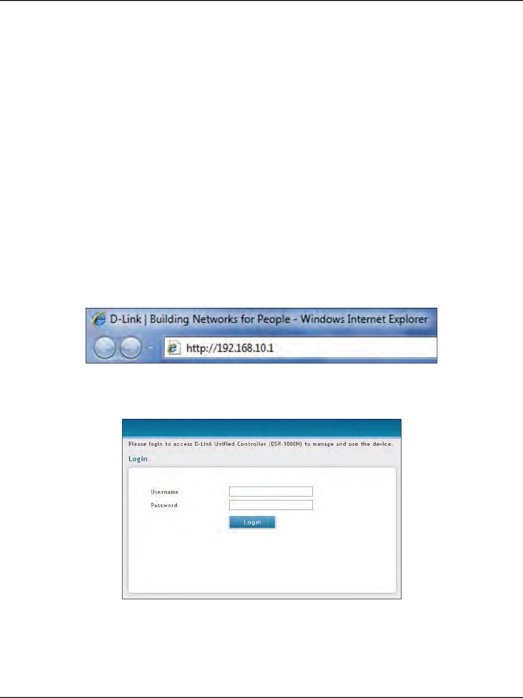
3. Launch a browser, enter the IP address for the LAN interface (default = http://192.168.10.1), and
then press Enter.
4. Enter your username (default = admin) and your password (default = admin), then click Login.
#1 Log in to the Web UI
The LAN connection may be through the wired Ethernet ports available on the router, or once the initial setup
is complete, the DSR may also be managed through its wireless interface. Access the router’s Web user interface
(Web UI) for management by using any web browser, such as Internet Explorer, Firefox, Chrome, or Safari.
5. The web management interface opens with the Status > Dashboard page. This page displays
general, LAN, and WLAN status information. You can return to this page at any time by clicking
Status > Dashboard.
D-Link DSR-Series User Manual 6
Section 3 - Basic Conguration
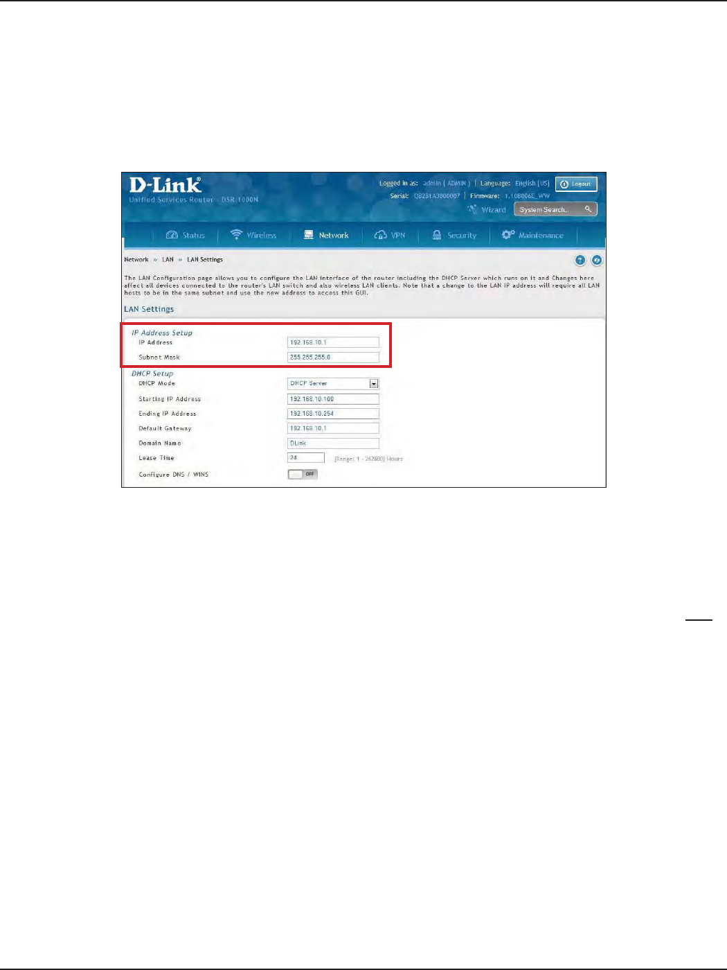
#2 Change LAN IP Address
1. Log in to the router.
2. Click Network > LAN > LAN Settings. The LAN Settings page will appear.
To change the LAN IP address of the router, follow the steps below:
Note: If you change the IP address and click Save, the Web UI will not respond. Open a new connection to the new IP
address and log in again. Be sure the LAN host (the machine used to manage the router) has obtained an IP address
from newly assigned pool (or has a static IP address in the router’s LAN subnet) before accessing the router via changed
IP address.
3. Under IP Address Setup, enter a new IP address for the router.
4. Enter a new subnet mask if needed.
5. Click Save at the bottom of the page.
D-Link DSR-Series User Manual 7
Section 3 - Basic Conguration
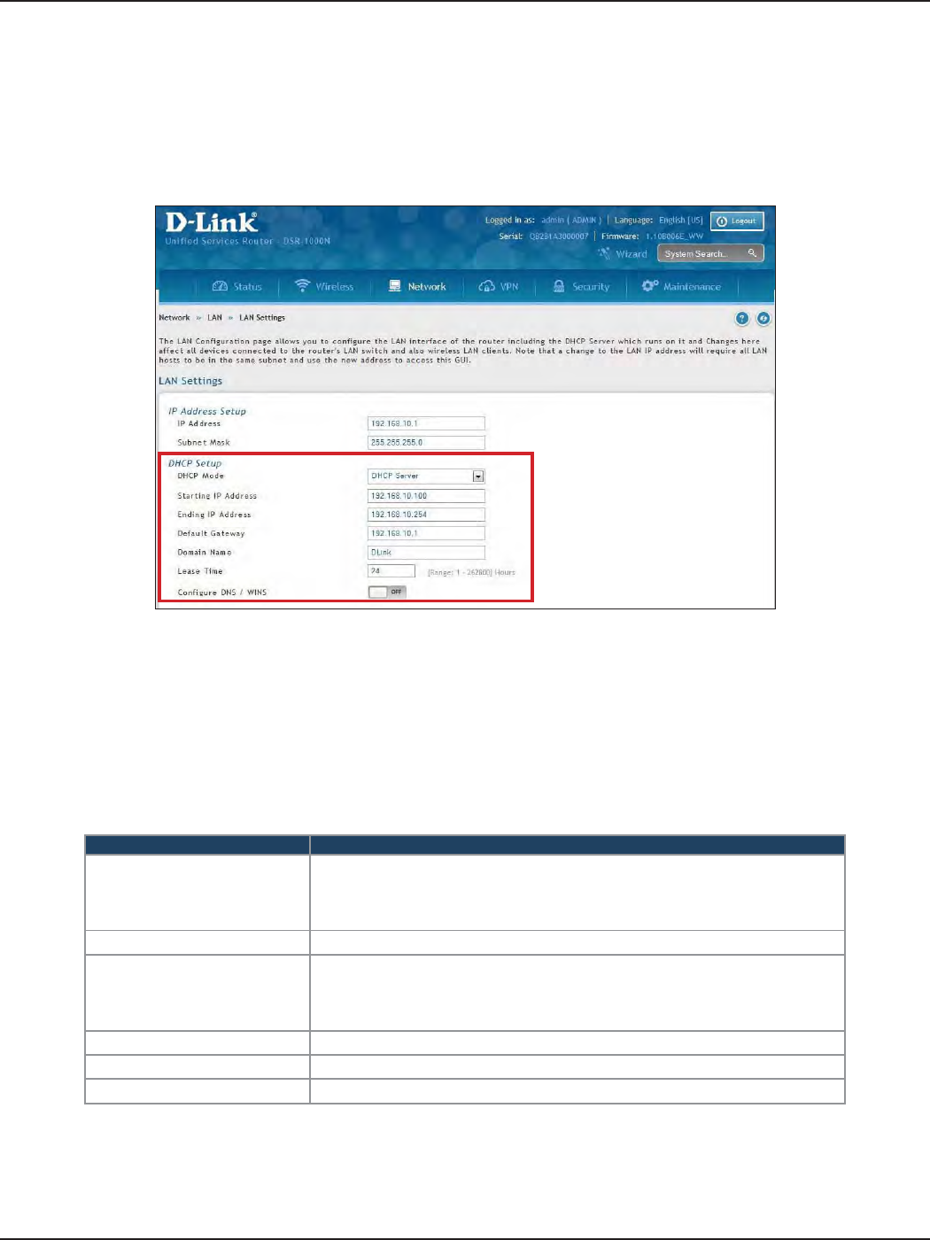
#3 Congure DHCP Server
1. Log in to the router.
2. Click Network > LAN > LAN Settings. The LAN Settings page will appear.
To change the DHCP settings of the router, follow the steps below:
3. From the DHCP Mode drop-down menu under DHCP Setup, select None (disable), DHCP Server
(enable), or DHCP Relay.
Note: DHCP Relay will allow DHCP clients on the LAN to receive IP address leases and corresponding
information from a DHCP server on a dierent subnet. When LAN clients make a DHCP request it will be
passed along to the server accessible via the Relay Gateway IP address you enter.
4. If enabled, ll in the following elds:
Field Description
Starting IP Address
Enter the starting IP address in the DHCP address pool. Any new DHCP cli-
ent joining the LAN is assigned an IP address within the starting and end-
ing IP address range. Starting and ending IP addresses should be in the
same IP address subnet as the wireless controller’s LAN IP address.
Ending IP Address Enter the ending IP address in the DHCP address pool.
Default Gateway
By default this setting is router’s LAN IP address. It can be customized to any
valid IP within the LAN subnet, in the event that the network’s gateway is not
this router. The DHCP server will give the congured IP address as the Default
Gateway to its DHCP clients.
Domain Name Enter a domain name.
Lease Time Enter the time, in hours, for which IP addresses are leased to clients.
Congure DNS/WINS Toggle to On and enter DNS and/or WINS server IP address(es).
5. Click Save at the bottom of the page.
D-Link DSR-Series User Manual 8
Section 3 - Basic Conguration
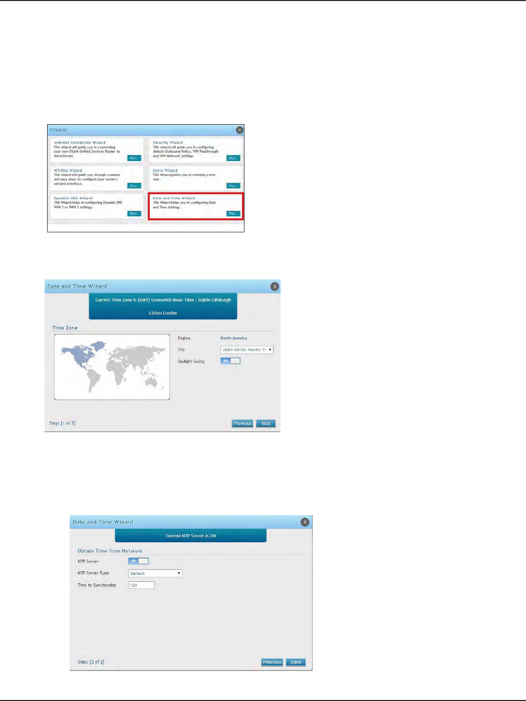
#4 Set Time and Date
1. Log in to the router.
2. Click Wizard in the upper-right side of the page. If you want to manually congure your date/time
settings, refer to “Date and Time” on page 162.
3. Click Run in the Date and Time Wizard box.
4. Click the continent from the map and then next to City, select your time zone from the drop-down
menu. Toggle Daylight Saving to ON if it applies to you and then click Next.
5. Toggle NTP server to ON to use a time server or toggle to OFF to manually enter the time and date.
6. If you selected ON, select either Default or Custom from the drop-down menu. If you selected Custom,
enter a primary and secondary NTP server address.
7. Enter the time to synchronize with the NTP server and click Save.
8. A summary page will appear. Verify your settings and then click Finish.
D-Link DSR-Series User Manual 9
Section 3 - Basic Conguration
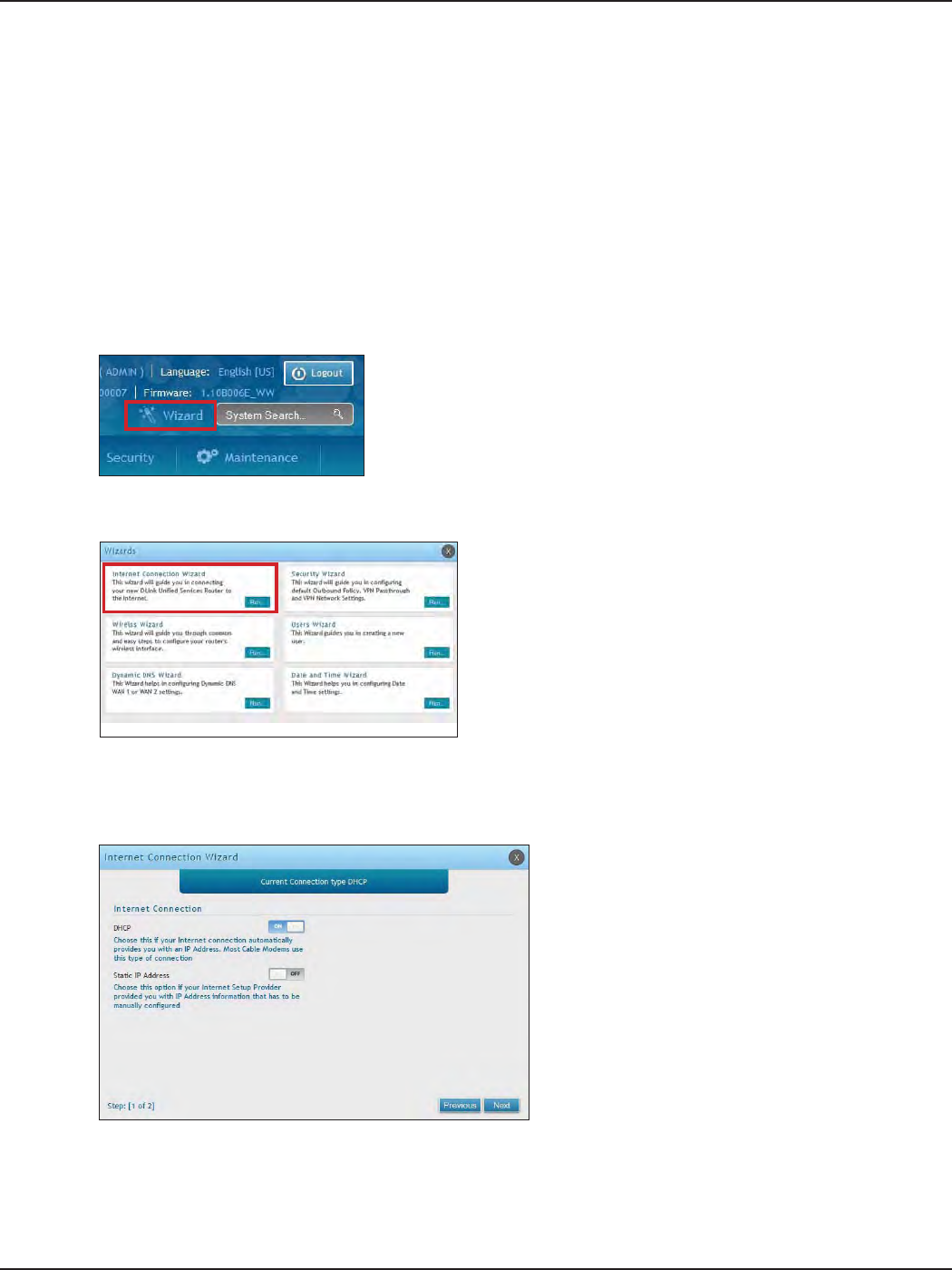
#5 Internet Connection Setup
1. Log in to the router.
2. Click Wizard in the upper-right side of the page. If you want to manually congure your Internet
settings, refer to “Connect to the Internet” on page 30.
This router has two WAN ports that can be used to establish a connection to the internet. It is assumed that you
have arranged for internet service with your Internet Service Provider (ISP). Please contact your ISP or network
administrator for the conguration information that will be required to setup the router. Supported Internet
connection types include Dynamic, Static, PPPoE, PPTP, L2TP, Japanese PPPoE, and Russian PPPoE/PPTP/L2TP.
To congure your router to connect to the Internet, follow the steps below:
3. Click Run in the Internet Connection Wizard box.
4. Toggle On next to either DHCP or Static IP Address and click Next. If your connection type is not listed,
refer to “Connect to the Internet” on page 30.
D-Link DSR-Series User Manual 10
Section 3 - Basic Conguration
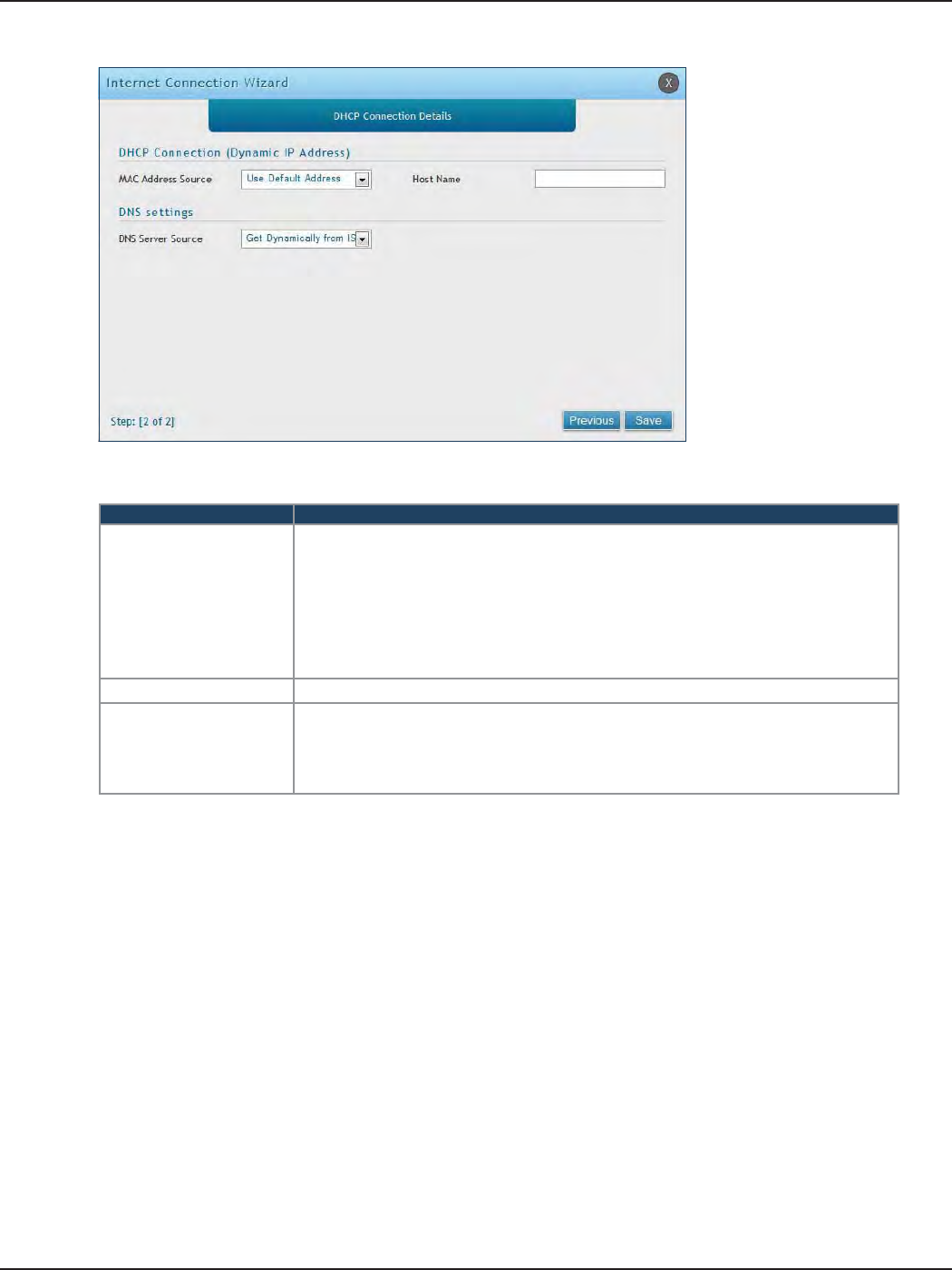
a. If you selected DHCP, complete the elds below:
Field Description
MAC Address Source
This MAC address will be recognized by your ISP. Select from the following three
options:
• Use Default Address - Uses the default MAC address of the router.
• Clone your PC’s MAC Address - Select to use the MAC address of the computer
you are currently connecting with.
• Use this MAC Address - Select to manually enter a MAC address and enter the
address in the box.
Host Name Enter a host name if required by your ISP.
DNS Server Source
Select from the following two options:
• Get Dynamically from ISP - Select to use the DNS servers assigned by your ISP.
• Use these DNS Servers - Select to manually enter a primary and secondary DNS
server address(es).
Skip to Step 5 on the bottom of the next page.
D-Link DSR-Series User Manual 11
Section 3 - Basic Conguration
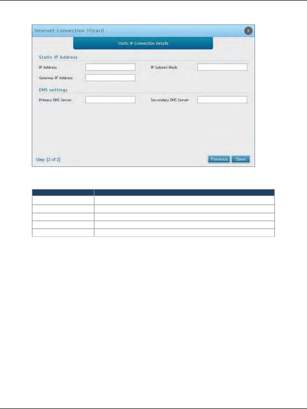
b. If you selected Static, complete the elds below:
Field Description
IP Address Enter the IP address assigned by your ISP.
Gateway IP Address Enter the gateway IP address assigned by your ISP.
IP Subnet Mask Enter the subnet mask assigned by your ISP.
Primary DNS Server Enter the primary DNS server IP address assigned by your ISP.
Secondary DNS Server Enter the secondary DNS server IP address assigned by your ISP.
5. Click Save. The router will reboot and attempt to connect to your ISP. Please allow one to two minutes
to connect.
D-Link DSR-Series User Manual 12
Section 3 - Basic Conguration
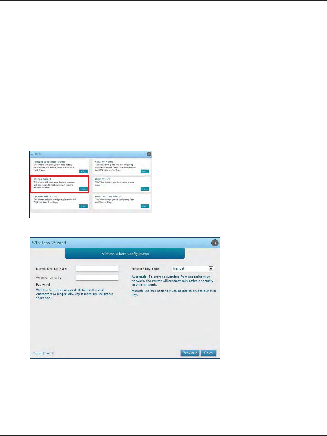
#6 Wireless Network Setup
1. Log in to the router.
2. Click Wizard in the upper-right side of the page.
This wizard provides a step-by-step guide to create and secure a new access point on the router. The network
name (SSID) is the AP identier that will be detected by supported clients. The Wizard uses a TKIP+AES cipher for
WPA / WPA2 security; depending on support on the client side, devices associate with this AP using either WPA
or WPA2 security with the same pre -shared key.
The wizard has the option to automatically generate a network key for the AP. This key is the pre-shared key
for WPA or WPA2 type security. Supported clients that have been given this PSK can associate with this AP. The
default (auto-assigned) PSK is “passphrase”.
5. Enter a SSID, which is the name of your wireless network.
6. Next to Network Key Type, select Manual.
7. Enter a password for the wireless network. Wireless devices connecting to this network must enter this
password to connect. The password is case-sensitive.
8. Click Save.
9. A window will appear with a summary of your settings. Click Finish.
3. Click Run in the Wireless Wizard box.
4. The wizard screen will appear.
D-Link DSR-Series User Manual 13
Section 3 - Basic Conguration
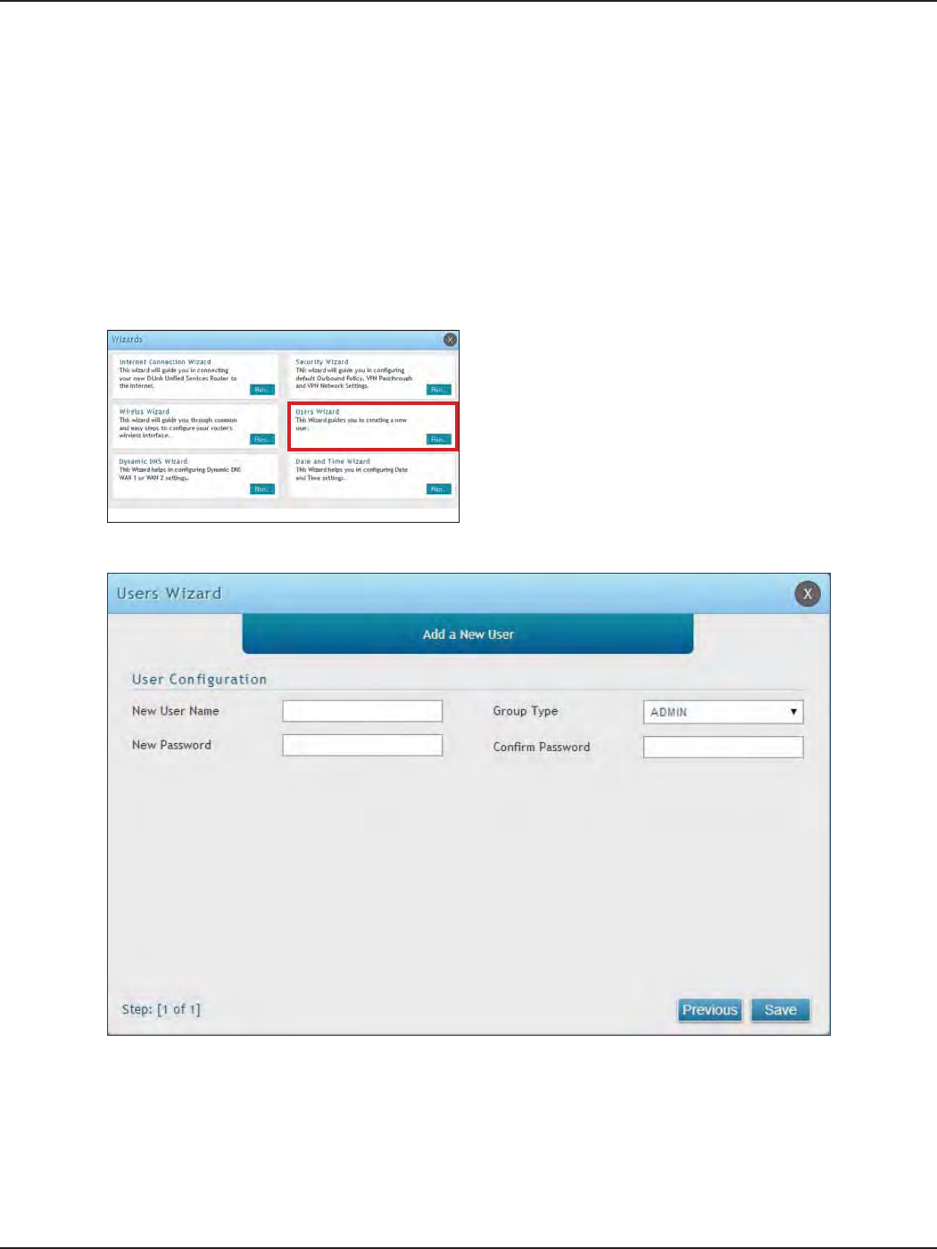
#7 Create Users
1. Log in to the router.
2. Click Wizard in the upper-right side of the page.
3. Click Run in the Users Wizard box.
The Users Wizard allows you to create user account that you can assign to groups. Refer to “Users” on page 129 for
more information. You may want to create Groups before users so you may assign them to groups as you create
them. To create groups, refer to “Groups” on page 125.
To create new users, follow the steps below:
5. Enter a unique user name.
6. Select the group type from the drop-down menu. For more information on groups, refer to “Groups”
on page 125.
7. Enter a password for the user.
8. Enter the password again for conrmation.
9. Click Save.
4. The wizard screen will appear.
D-Link DSR-Series User Manual 14
Section 3 - Basic Conguration
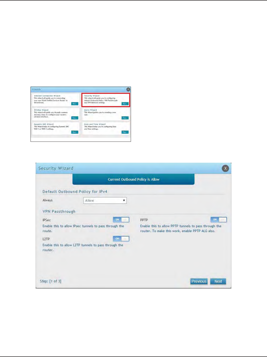
#8 Security/VPN Wizard
1. Log in to the router.
2. Click Wizard in the upper-right side of the page.
3. Click Run in the Security Wizard box.
The Security Wizard allows you to enable VPN passthrough and create a VPN.
Follow the steps below:
4. The wizard screen will appear.
5. Select the default outbound policy from the drop-down menu.
6. Toggle which type(s) of VPN you want allowed to pass through the router to ON and click Next.
D-Link DSR-Series User Manual 15
Section 3 - Basic Conguration
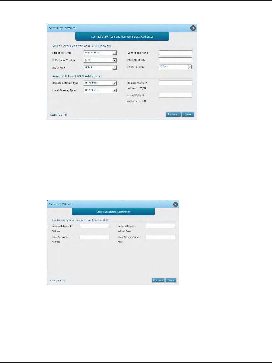
Note: The IP address range used on the remote LAN must be dierent from the IP address range used on the local LAN.
7. You can quickly create both IKE and VPN policies. Once the IKE or VPN policy is created, you can modify
it as required.
8. From the Select VPN Type drop-down menu, select either Site to Site or Remote Access.
9. Next to Connection Name, enter a name for this VPN connection.
10. Next to IP Protocol Version, select either IPv4 or IPv6.
11. Next to IKE Version, select the version of IKE.
12. Next to Pre-Shared Key, enter the pre-shared key used.
13. Next to Local Gateway, select which WAN port used for the local gateway.
14. Next to Remote Gateway Type and Local Gateway Type, select either IP Address or FQDN.
15. Enter the Remote and Local WAN IP Address or FQDN and click Next.
16. Enter the remote network IP address and subnet mask.
17. Enter the local network IP address and subnet mask.
18. Click Save.
D-Link DSR-Series User Manual 16
Section 3 - Basic Conguration
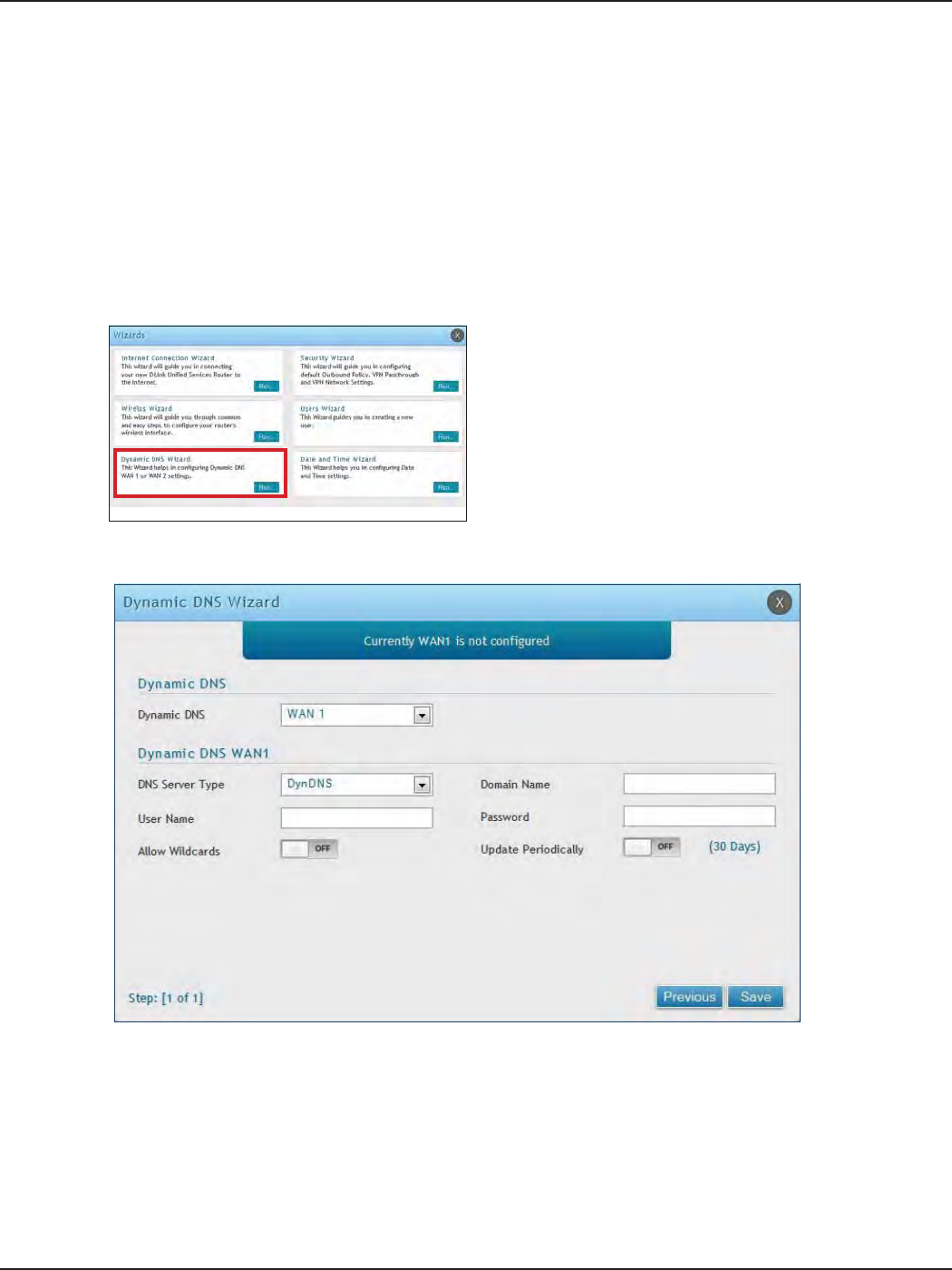
#9 Dynamic DNS Wizard
Dynamic DNS (DDNS) is an Internet service that allows routers with varying public IP addresses to be located
using Internet domain names. To use DDNS, you must setup an account with a DDNS provider such as DynDNS.
org, D-Link DDNS, or Oray.net. Refer to “Dynamic DNS Settings” on page 53 for more information.
Follow the steps below:
5. Next to Dynamic DNS, select WAN1 or WAN2.
6. Select the DNS Server Type from the drop-down menu.
7. Depending on your service, enter your DDNS user name, password, and domain name.
8. Toggle Allow Wildcards to ON if required by your DDNS service.
9. Toggle Update Periodically to ON to auto update every 30 days.
10. Click Save.
1. Log in to the router.
2. Click Wizard in the upper-right side of the page.
3. Click Run in the Dynamic DNS Wizard box.
4. The wizard screen will appear.

D-Link DSR-Series User Manual 17
Section 4 - LAN Conguration
LAN Conguration
By default, the router functions as a Dynamic Host Conguration Protocol (DHCP) server to the hosts on the LAN
and WLAN network. With DHCP, PCs and other LAN devices can be assigned IP addresses as well as addresses
for DNS servers, Windows Internet Name Service (WINS) servers, and the default gateway. With DHCP server
enabled the router’s IP address serves as the gateway address for LAN and WLAN clients. The PCs in the LAN are
assigned IP addresses from a pool of addresses specied in this procedure. Each pool address is tested before it
is assigned to avoid duplicate addresses on the LAN.
For most applications, the default DHCP and TCP/IP settings are satisfactory. If you want another PC on your
network to be the DHCP server or if you are manually conguring the network settings of all of your PCs, set the
DHCP mode to ‘none’. DHCP relay can be used to forward DHCP lease information from another DHCP server on
the network. This is particularly useful for wireless clients.
Instead of using a DNS server, you can use a Windows Internet Naming Service (WINS) server. A WINS server is the
equivalent of a DNS server but uses the NetBIOS protocol to resolve host names. The router includes the WINS
server IP address in the DHCP conguration when acknowledging a DHCP request from a DHCP client.
You can also enable DNS proxy for the LAN. When this is enabled the router then as a proxy for all DNS requests
and communicates with the ISP’s DNS servers. When disabled all DHCP clients receive the DNS IP addresses of
the ISP.
D-Link DSR-Series User Manual 18
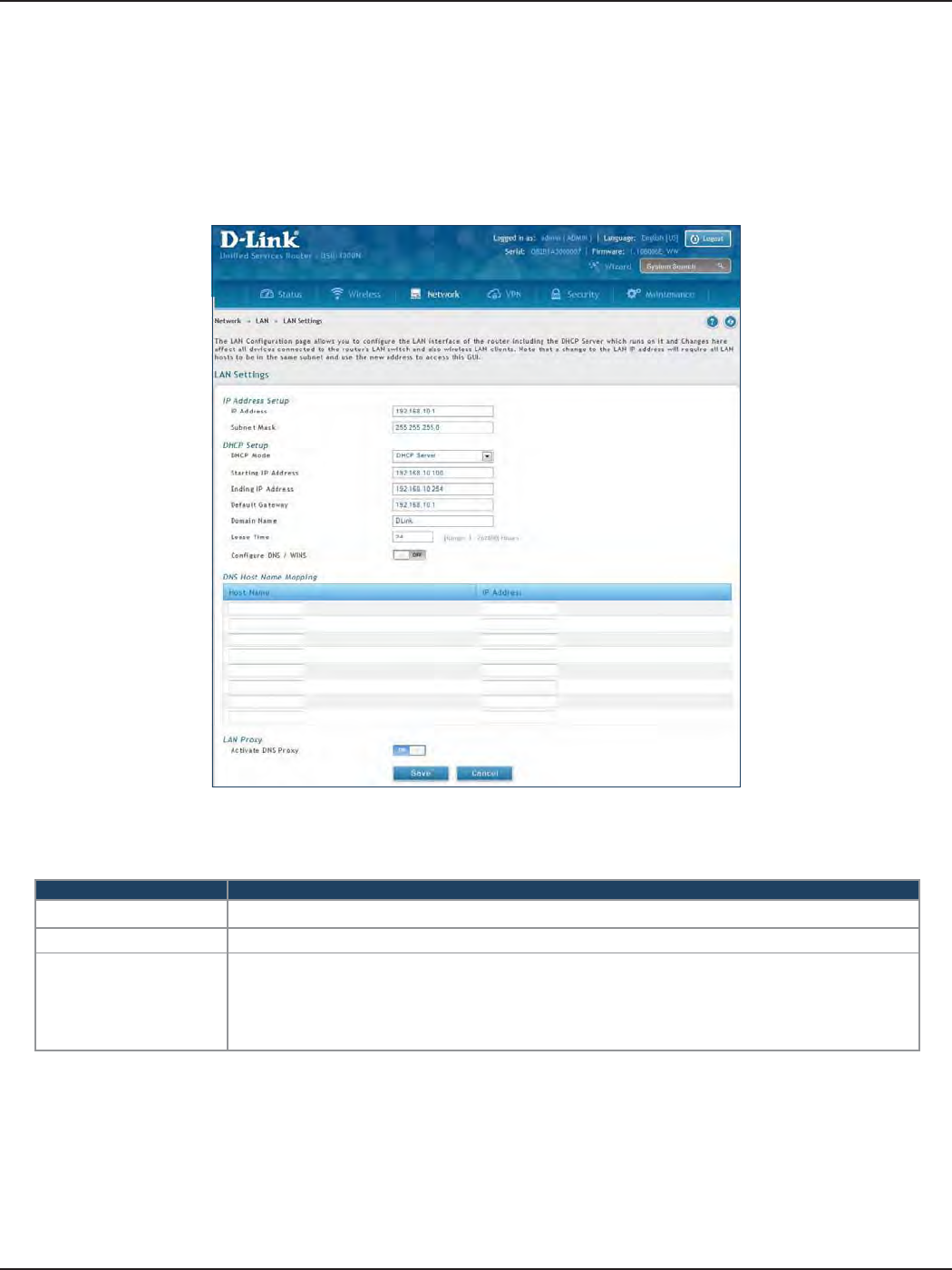
Section 4 - LAN Conguration
Field Description
IP Address Enter an new IP address for the router. Default is 192.168.10.1.
Subnet Mask Enter the subnet mask for your network. Default is 255.255.255.0.
DHCP Mode
Select one of the following modes:
• None - Turns o DHCP.
• DHCP Server (default) - The router will act as the DHCP server on your network.
• DHCP Relay - DHCP clients on your network will receive IP address leases from a DHCP
server on a dierent subnet.
LAN Settings
Path: Network > LAN > LAN Settings
To congure the LAN settings on the router:
1. Click Network > LAN > LAN Settings.
2. Complete the elds in the table below and click Save.
D-Link DSR-Series User Manual 19
Section 4 - LAN Conguration
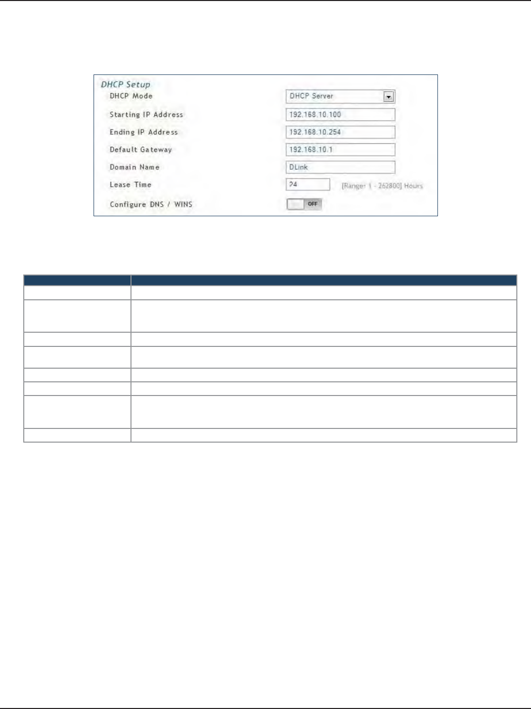
DHCP Server
Field Description
DHCP Mode Select DHCP Server from the drop-down menu.
Starting IP Address
Enter the starting IP address in the DHCP address pool. Any new DHCP client joining the LAN is
assigned an IP address within the starting and ending IP address range. Starting and ending IP
addresses must be in the same IP address subnet as the router’s LAN IP address.
Ending IP Address Enter the ending IP address in the DHCP address pool.
Default Gateway Enter the default gateway IP address you want to assign to your DHCP clients. This IP is usually
the router’s LAN IP address (default is 192.168.10.1).
Domain Name Enter a domain name.
Lease Time Enter the time, in hours, for which IP addresses are leased to clients.
Congure DNS/WINS
Toggle to On to manually enter DNS and/or WINS server IP address(es). If set to O, your router’s
LAN IP address will be assigned the DNS server to your clients and the router will get the DNS
information from your ISP.
Save Click Save at the bottom to save and activate your settings.
2. Complete the elds in the table below and click Save.
1. Select DHCP Server from the drop-down menu.
D-Link DSR-Series User Manual 20
Section 4 - LAN Conguration
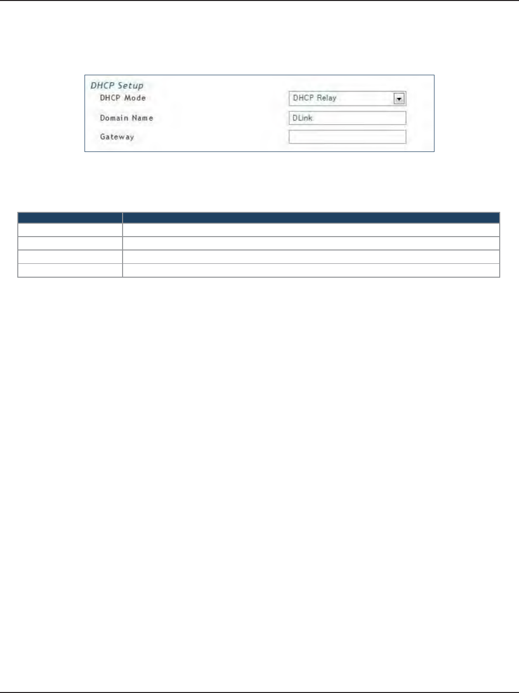
DHCP Relay
Field Description
DHCP Mode Select DHCP Relay from the drop-down menu.
Domain Name Enter the domain name of your network.
Gateway Enter the relay gateway IP address.
Save Click Save at the bottom to save and activate your settings.
2. Complete the elds in the table below and click Save.
1. Select DHCP Relay from the drop-down menu.
D-Link DSR-Series User Manual 21
Section 4 - LAN Conguration
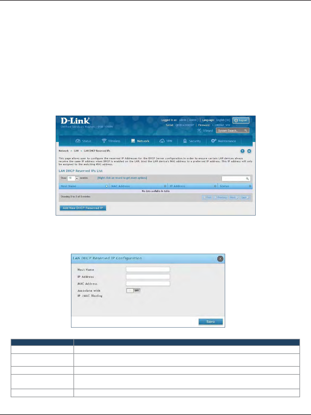
DHCP Reserved IPs
The router’s DHCP server can assign IP settings to your clients on your network by adding a client’s MAC address
and the IP address to be assigned. Whenever the router receives a request from a client, the MAC address of that
client is compared with the MAC address list present in the database. If an IP address is already assigned to that
computer or device in the database, the customized IP address is congured otherwise an IP address is assigned
to the client automatically from the DHCP pool.
Field Description
Host Name Enter a host name for this device. Do not use spaces.
IP Address Enter the IP address you want to assign to this device. Note that this IP address must be in the
same range as the starting/ending IP address under DHCP Settings.
MAC Address Enter the MAC address of this device (xx:xx:xx:xx:xx:xx format). This is not case-sensitive.
Associate with IP/MAC
Binding Toggle ON to associate this device’s information with IP/MAC binding.
Save Click Save to save and activate your settings.
Path: Network > LAN > LAN DHCP Reserved IPs
To create DHCP reservations:
1. Click Network > LAN > LAN DHCP Reserved IPs.
2. Click Add New DHCP Reserved IP.
3. Enter the following information and click Save.
D-Link DSR-Series User Manual 22
Section 4 - LAN Conguration
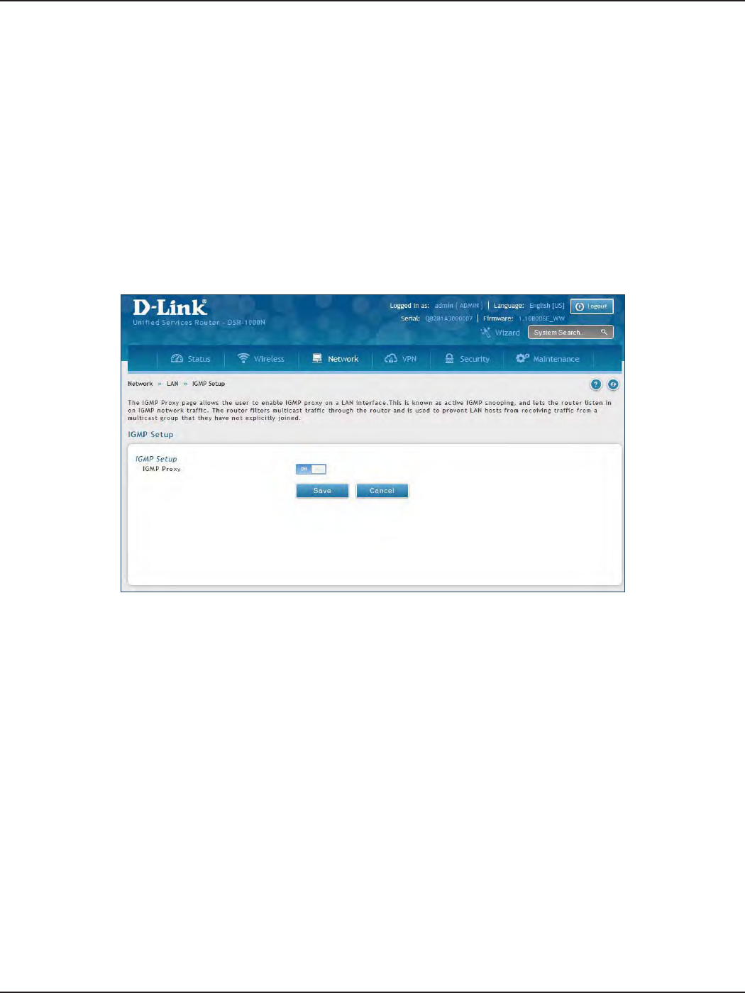
IGMP Setup
Path: Network > LAN > IGMP Setup
IGMP snooping (IGMP Proxy) allows the router to ‘listen’ in on IGMP network trac through the router. This then
allows the router to lter multicast trac and direct it only to hosts that need this stream. This is helpful when
there is a lot of multicast trac on the network where all LAN hosts do not need to receive this multicast trac.
To enable IGMP Proxy:
1. Click Network > LAN > IGMP Setup.
2. Toggle IGMP Proxy to On.
3. Click Save.
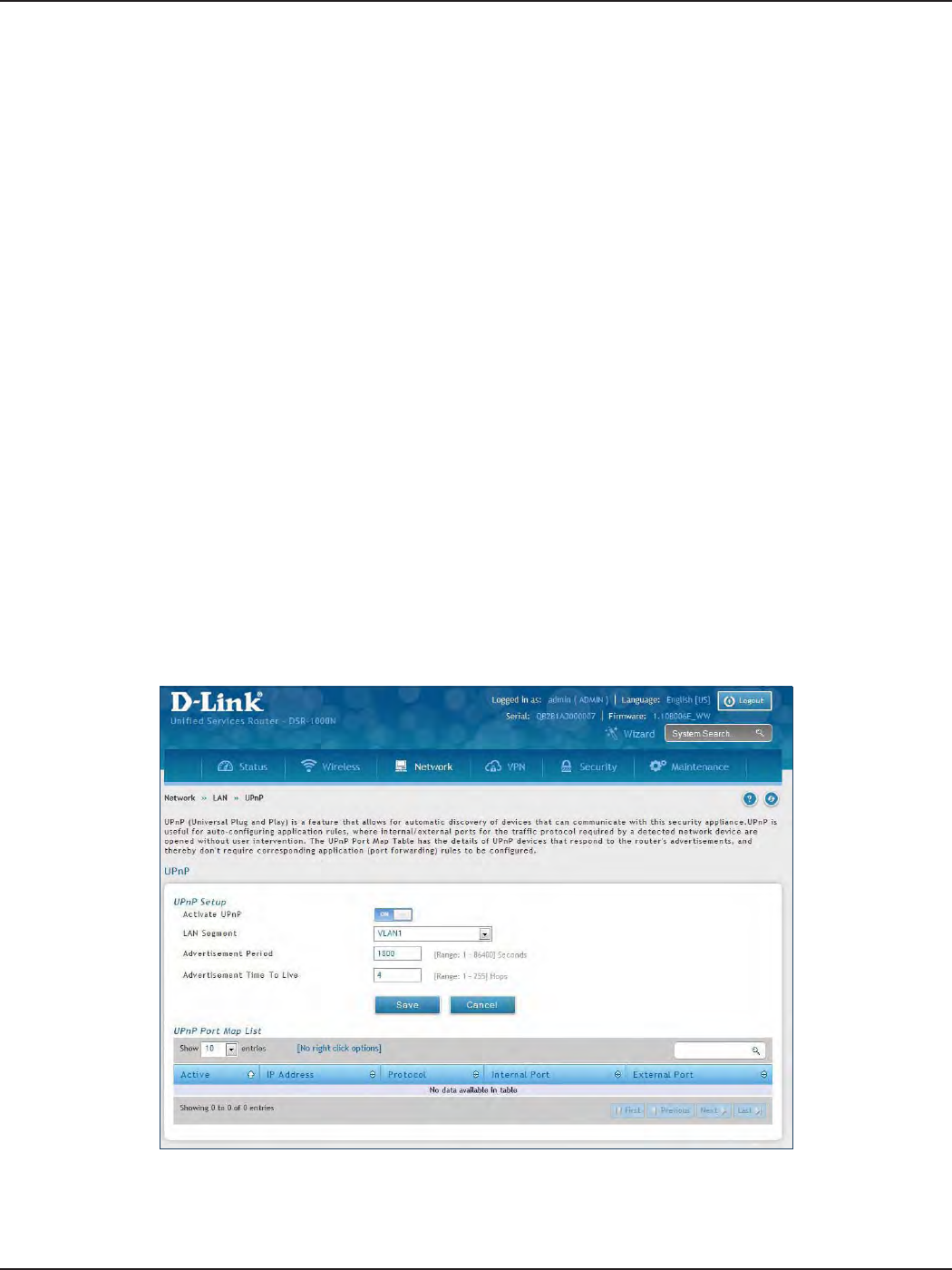
D-Link DSR-Series User Manual 23
Section 4 - LAN Conguration
UPnP Setup
Path: Network > LAN > UPnP
Universal Plug and Play (UPnP) is a feature that allows the router to discover devices on the network that can
communicate with the router and allow for auto-conguration. If a network device is detected by UPnP, the
router can open internal or external ports for the trac protocol required by that network device. If disabled, the
router will not allow for automatic device conguration and you may have to manually open/forward ports to
allow applications to work.
To congure the UPnP settings:
1. Click Network > LAN > UPnP.
2. Toggle Activate UPnP to On.
3. Select a VLAN from the LAN Segment drop-down menu.
4. Enter a value for Advertisement Period. This is the frequency that the router broadcasts UPnP information
over the network. A large value will minimize network trac but cause delays in identifying new UPnP
devices to the network.
5. Enter a value for Advertisement Time to Live. This is the number of steps a packet is allowed to propagate
before being discarded. Small values will limit the UPnP broadcast range. A default of 4 is typical for
networks with a few number of switches.
6. Click Save.
7. Your entry will be displayed in the UPnP Port Map List. To edit or delete, right-click an entry and select
the action from the menu. Repeat steps 2-6 to add multiple entries.
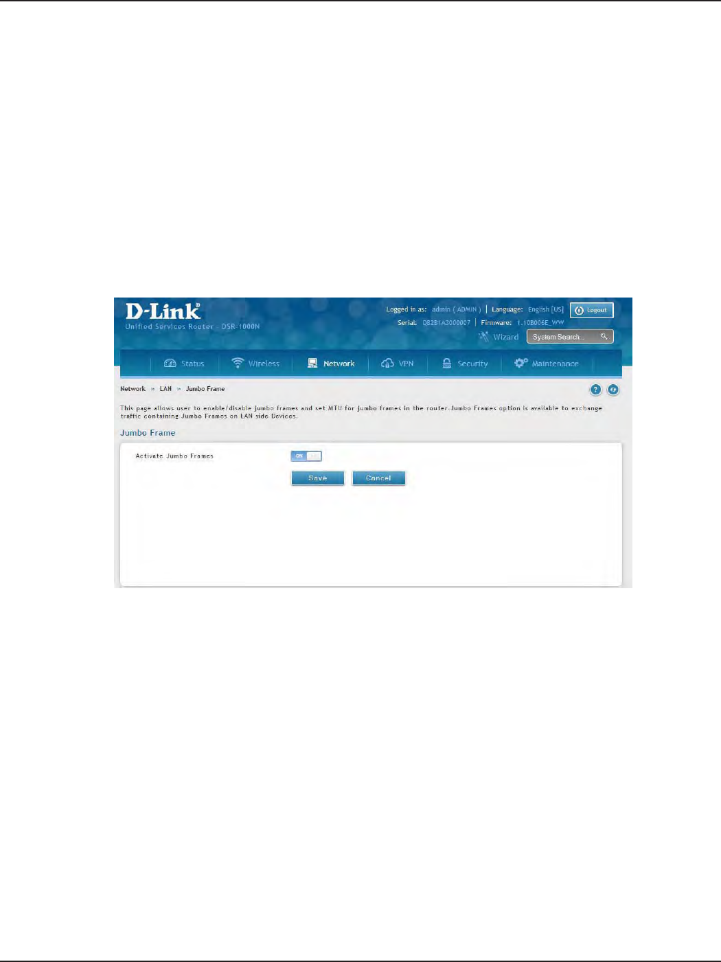
D-Link DSR-Series User Manual 24
Section 4 - LAN Conguration
Jumbo Frames
Jumbo frames are Ethernet frames with more than 1500 bytes of payload. When this option is enabled, the LAN
devices can exchange information at Jumbo frames rate.
Path: Network > LAN > Jumbo Frames
To enable jumbo frames:
1. Click Network > LAN > Jumbo Frames.
2. Toggle Activate Jumbo Frames to On.
3. Click Save.
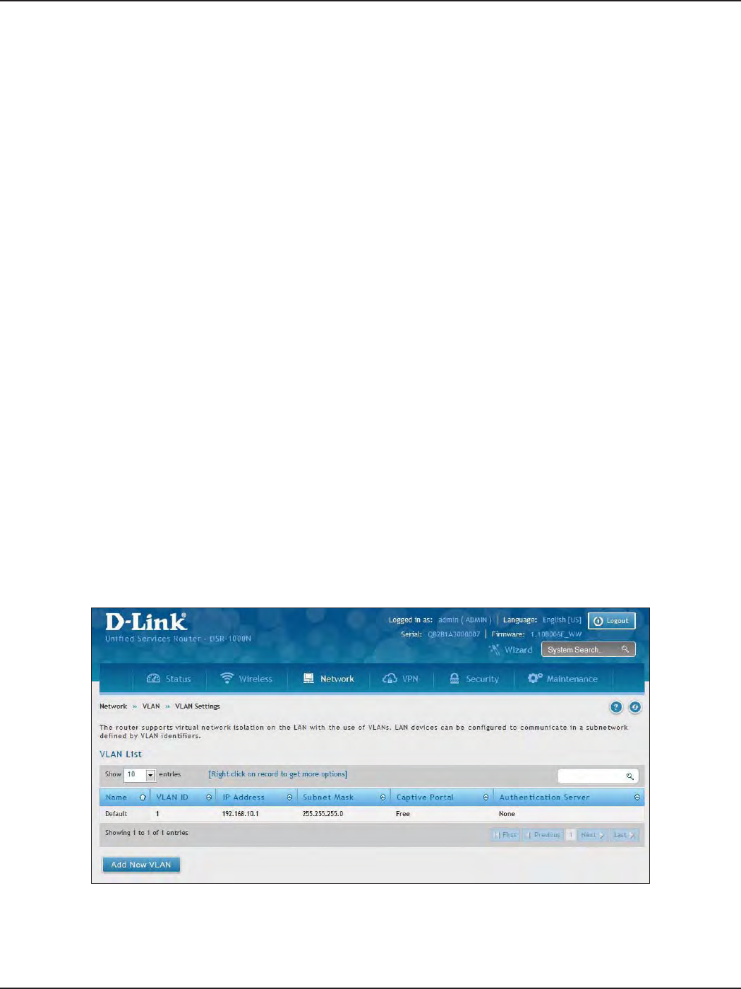
D-Link DSR-Series User Manual 25
Section 4 - LAN Conguration
VLAN
VLAN Settings
Path: Network > VLAN > VLAN Settings
The VLAN List page displays a list of congured VLANs by name and VLAN ID. A VLAN membership can be created
by clicking the Add New VLAN button below the list.
A VLAN membership entry consists of a VLAN identier and the numerical VLAN ID which is assigned to the VLAN
membership. The VLAN ID value can be any number from 2 to 4091. VLAN ID 1 is reserved for the default VLAN,
which is used for untagged frames received on the interface.
The router supports virtual network isolation on the LAN with the use of VLANs. LAN devices can be congured
to communicate in a sub network dened by VLAN identiers. LAN ports can be assigned unique VLAN IDs so
that trac to and from that physical port can be isolated from the general LAN.
VLAN ltering is particularly useful to limit broadcast packets of a device in a large network VLAN support is
enabled by default in the router. In the VLAN Conguration page, enable VLAN support on the router and then
proceed to the next section to dene the virtual network.
To create a new VLAN:
1. Click Network > LAN > VLAN Settings.
2. Click Add New VLAN at the bottom.
3. Enter the following required information from the table on the next page.
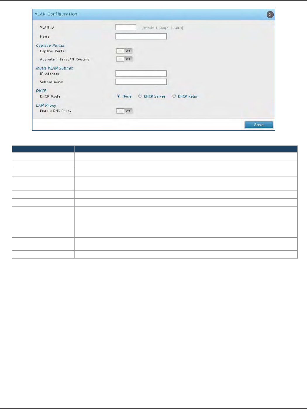
D-Link DSR-Series User Manual 26
Section 4 - LAN Conguration
Field Description
VLAN ID Enter a number between 2 and 4053.
Name Enter a name for your VLAN.
Captive Portal Toggle ON to enable Captive Portal (refer to the next page for more information).
Activate InterVLAN
Routing
Toggle ON to allow routing between multiple VLANs or OFF to deny communication between
VLANs.
IP Address Enter the IP address for the VLAN.
Subnet Mask Enter the subnet mask for the VLAN.
DHCP Mode
Select one of the following modes:
• None - Turns o DHCP for your VLAN.
• DHCP Server (default) - The router will act as the DHCP server for your VLAN.
• DHCP Relay - DHCP clients on your VLAN will receive IP address leases from a DHCP server
on a dierent subnet.
Enable DNS Proxy Toggle ON to enable the router to act as a proxy for all DNS requests and communicate with the
ISP’s DNS servers.
Save Click Save to save and activate your settings.
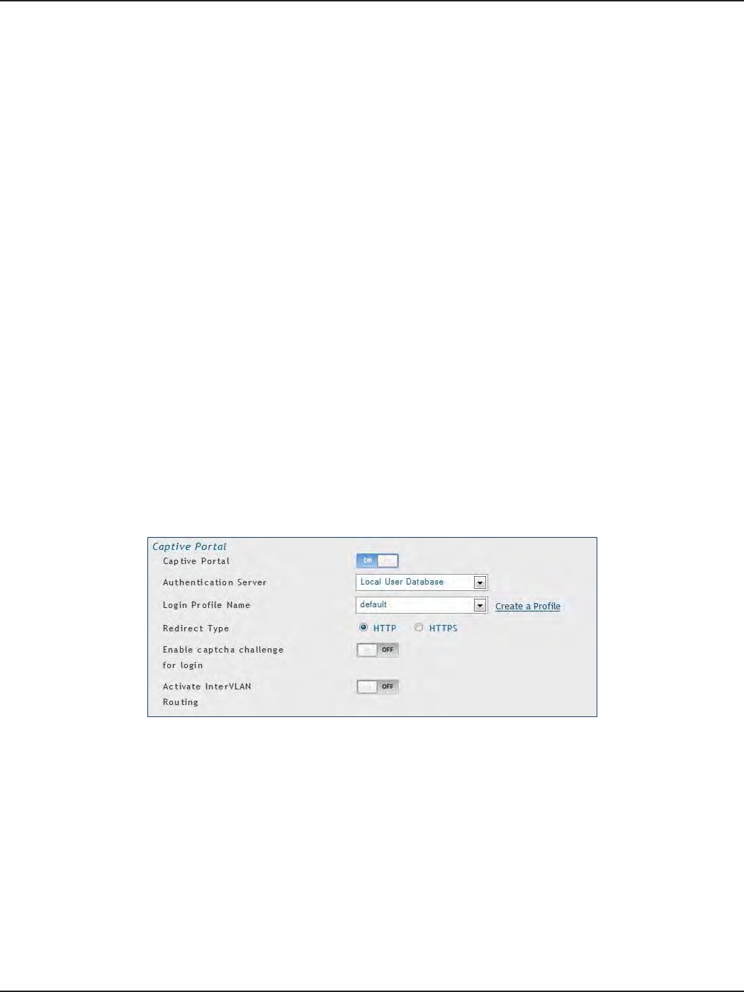
D-Link DSR-Series User Manual 27
Section 4 - LAN Conguration
Captive Portal
Note: The DSR-150/150N/250/250N routers do not have support for the Captive Portal feature. Captive Portal is
available for LAN users only and not for DMZ hosts.
Captive Portals can be enabled on a per-VLAN basis. Hosts of a particular VLAN can be directed to authenticate
via the Captive Portal, which may be a customized portal with unique instructions and branding as compared to
another VLAN. The most critical aspect of this conguration page is choosing the authentication server. All users
(VLAN hosts) that want to gain internet access via the selected Captive Portal will be authenticated through the
selected server.
To enable Creative Portal to a specic VLAN:
1. Click Network > LAN > VLAN Settings.
2. Click Add New VLAN at the bottom or right-click an existing VLAN and select Edit.
3. Toggle Captive Portal to ON.
4. Next to Authentication Server, select an authentication server from the drop-down menu.
5. Next to Login Prole Name, select a prole from the drop-down or click Create a Prole to create a new
one.
6. Select either HTTP or HTTPS for the redirect type.
7. If you want users to enter a CAPTCHA challenge at login, toggle to ON.
8. If you would like communication between VLANs, toggle Activate InterVLAN Routing to ON.
9. Make any other changes/selections and click Save.
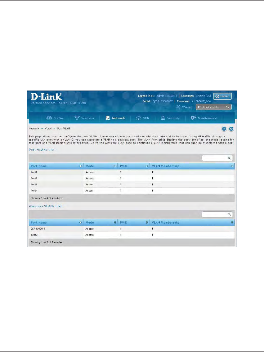
D-Link DSR-Series User Manual 28
Section 4 - LAN Conguration
Port/Wireless VLAN
Path: Network > VLAN Settings > Port VLAN
In order to tag all trac through a specic LAN port with a VLAN ID, you can associate a VLAN to a physical port
and wireless segment.
VLAN membership properties for the LAN and wireless LAN are listed on this page. The VLAN Port table displays
the port identier, the mode setting for that port and VLAN membership information. The conguration page is
accessed by selecting one of the four physical ports or a congured access point and clicking Edit.
To edit, right-click on the port and select Edit. The edit page oers the following conguration options:
• Mode: The mode of this VLAN can be General, Access (default), or Trunk. Refer to the next page for
more information on the dierent modes.
• Select PVID for the port when General mode is selected.
• Congured VLAN memberships will be displayed on the VLAN Membership Conguration for the
port. By selecting one more VLAN membership options for a General or Trunk port, trac can be
routed between the selected VLAN membership IDs.
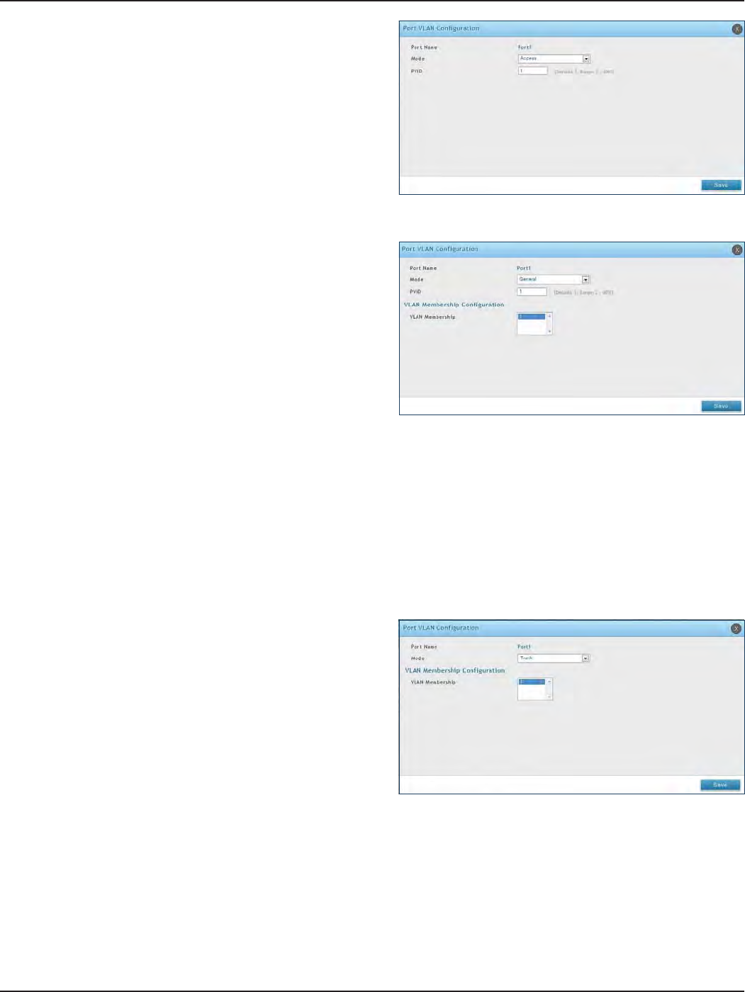
D-Link DSR-Series User Manual 29
Section 4 - LAN Conguration
In Access mode the port is a member of a single VLAN
(and only one). All data going into and out of the port is
untagged. Trac through a port in access mode looks
like any other Ethernet frame.
In General mode the port is a member of a user selectable
set of VLANs. The port sends and receives data that is
tagged or untagged with a VLAN ID. If the data into the
port is untagged, it is assigned the dened PVID.
For example, if Port 3 is a General port with PVID 3, then
the untagged data into Port 3 will be assigned PVID 3. All
tagged data sent out of the port with the same PVID will
be untagged. This is mode is typically used with IP Phones
that have dual Ethernet ports. Data coming from phone
to the switch port on the router will be tagged. Data
passing through the phone from a connected device will
be untagged.
Note: The DSR-150/150N do not support General mode due
to hardware limitations.
In Trunk mode the port is a member of a user
selectable set of VLANs. All data going into and out
of the port is tagged. Untagged coming into the port
is not forwarded, except for the default VLAN with
PVID=1, which is untagged. Trunk ports multiplex
trac for multiple VLANs over the same physical link.
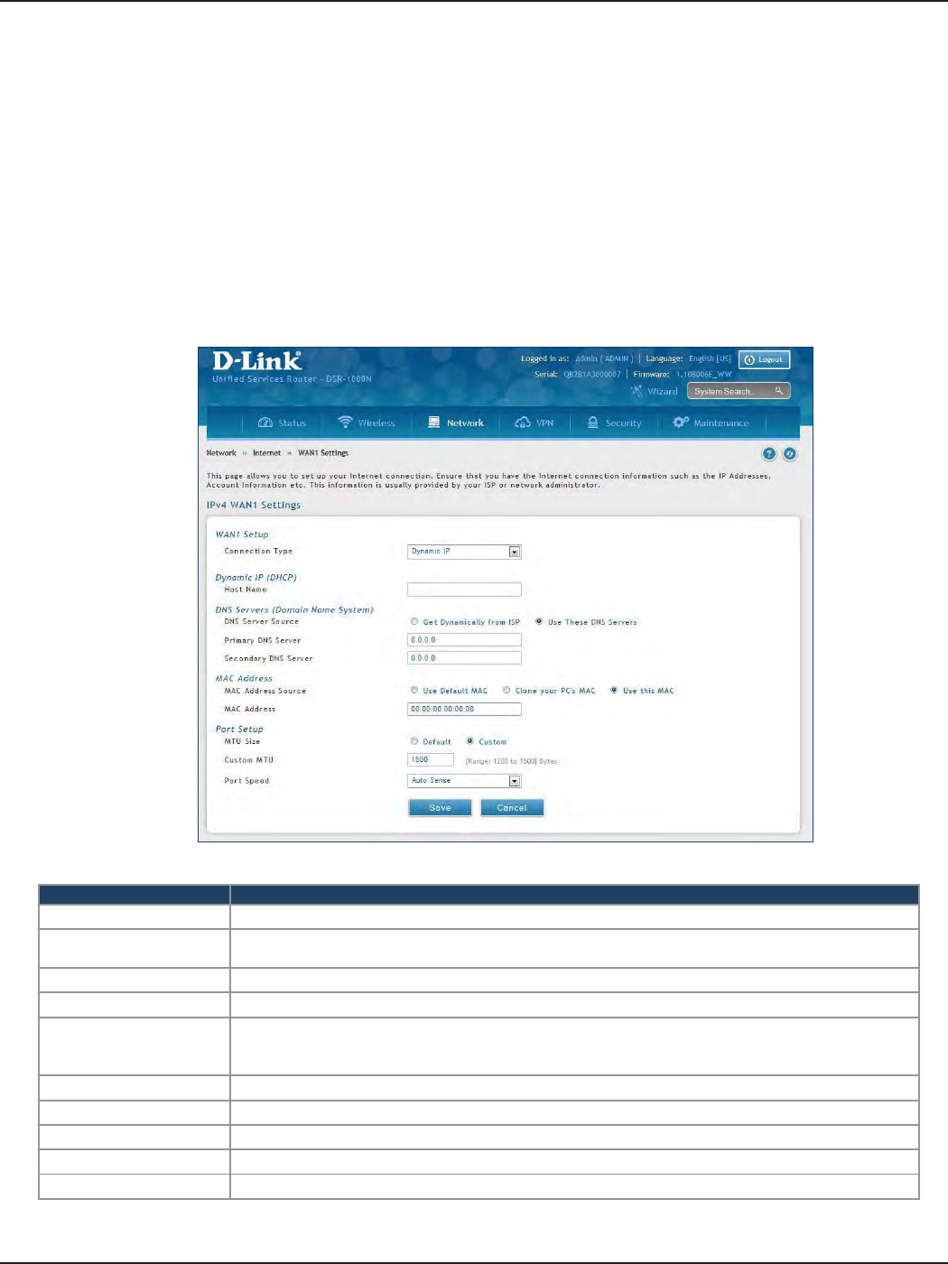
D-Link DSR-Series User Manual 30
Section 5 - Connect to the Internet
Connect to the Internet
This router has two WAN ports that can be used to establish a connection to the internet. It is assumed that you
have arranged for internet service with your Internet Service Provider (ISP). Please contact your ISP or network
administrator for the conguration information that will be required to setup the router.
Dynamic IP
Path: Network > Internet > WAN1 Settings
Select Dynamic IP (DHCP) to obtain IP address information automatically from your Internet Service Provider.
Field Description
Host Name Enter a host name if required by your ISP.
DNS Server Source Select either Get Dynamically from ISP or Use These DNS Servers to manually enter DNS
servers
Primary DNS Server If you selected “Use These DNS Servers”, enter the primary DNS server IP address.
Secondary DNS Server If you selected “Use These DNS Servers”, enter the secondary DNS server IP address.
MAC Address Source
Select Use Default MAC to use the MAC address from the WAN1 port to associate with your
modem/ISP, Clone your PC’s MAC to use the MAC address of the computer you are currently
using to associate with your modem/ISP, or Use this MAC to manually enter a MAC address.
MAC Address If you selected Use this MAC, enter the MAC address you want to associate with your ISP.
MTU Size Select to use the default MTU value (1500) or select Custom to enter your own value.
Custom MTU Enter a MTU value to optimize performance with your ISP.
Port Speed Select a value from the drop-down menu. The default value is Auto-Sense.
Save Click Save to save and activate your settings.
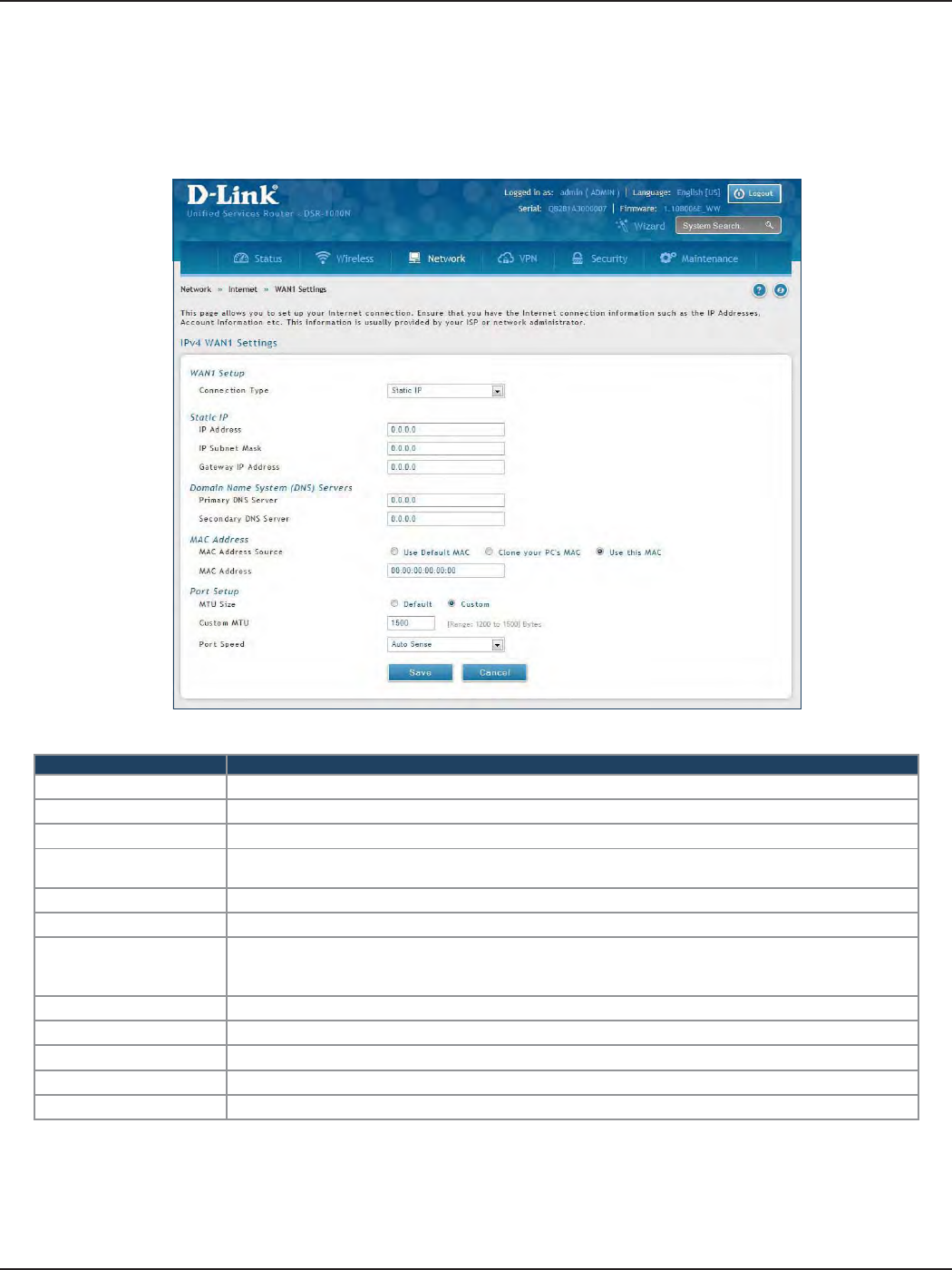
D-Link DSR-Series User Manual 31
Section 5 - Connect to the Internet
Static IP
Path: Network > Internet > WAN1 Settings
Select Static IP to manually enter the Internet settings supplied by your Internet Service Provider.
Field Description
IP Address Enter the IP address supplied by your ISP.
IP Subnet Mask Enter the subnet mask supplied by your ISP.
Gateway IP Address Enter the gateway IP address supplied by your ISP.
DNS Server Source Select either Get Dynamically from ISP or Use These DNS Servers to manually enter DNS
servers.
Primary DNS Server If you selected “Use These DNS Servers”, enter the primary DNS server IP address.
Secondary DNS Server If you selected “Use These DNS Servers”, enter the secondary DNS server IP address.
MAC Address Source
Select Use Default MAC to use the MAC address from the WAN1 port to associate with your
modem/ISP, Clone your PC’s MAC to use the MAC address of the computer you are currently
using to associate with your modem/ISP, or Use this MAC to manually enter a MAC address.
MAC Address If you selected Use this MAC, enter the MAC address you want to associate with your ISP.
MTU Size Select to use the default MTU value (1500) or select Custom to enter your own value.
Custom MTU Enter a MTU value to optimize performance with your ISP.
Port Speed Select a value from the drop-down menu. The default value is Auto-Sense.
Save Click Save to save and activate your settings.
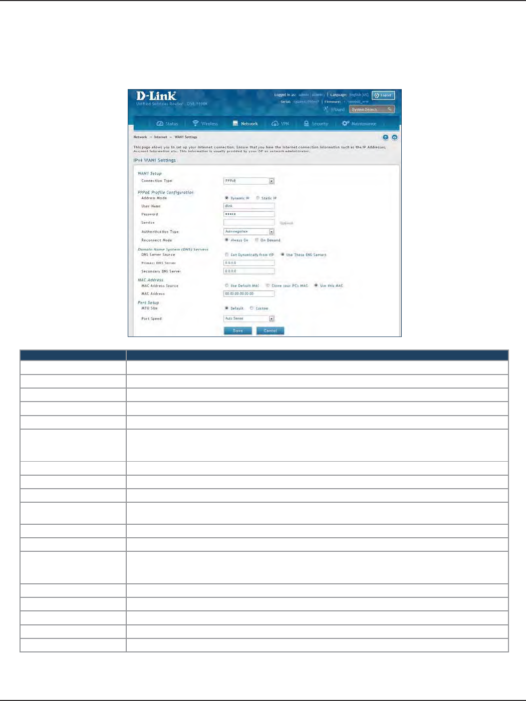
D-Link DSR-Series User Manual 32
Section 5 - Connect to the Internet
PPPoE
Path: Network > Internet > WAN1 Settings
Select PPPoE to enter the PPPoE Internet settings supplied by your Internet Service Provider.
Field Description
Address Mode Select Dynamic IP or Static IP (IP settings supplied by your ISP).
User Name Enter your PPPoE user name.
Password Enter your PPPoE password.
Service Enter if your ISP requires it.
Authentication Type Select the authentication type from the drop-down menu.
Reconnect Mode
Some ISPs may require you to pay for usage time. Select On Demand if this is the case. This will
have the router connect to the Internet only when you initiate an Internet connection. Select
Always On to have the router stay connected to the Internet.
IP Address If you selected Static IP, enter the IP address supplied by your ISP.
IP Subnet Mask If you selected Static IP, enter the subnet mask supplied by your ISP.
Gateway IP Address If you selected Static IP, enter the gateway IP address supplied by your ISP.
DNS Server Source Select either Get Dynamically from ISP or Use These DNS Servers to manually enter DNS
servers.
Primary DNS Server If you selected “Use These DNS Servers”, enter the primary DNS server IP address.
Secondary DNS Server If you selected “Use These DNS Servers”, enter the secondary DNS server IP address.
MAC Address Source
Select Use Default MAC to use the MAC address from the WAN1 port to associate with your
modem/ISP, Clone your PC’s MAC to use the MAC address of the computer you are currently
using to associate with your modem/ISP, or Use this MAC to manually enter a MAC address.
MAC Address If you selected Use this MAC, enter the MAC address you want to associate with your ISP.
MTU Size Select to use the default MTU value (1500) or select Custom to enter your own value.
Custom MTU Enter a MTU value to optimize performance with your ISP.
Port Speed Select a value from the drop-down menu. The default value is Auto-Sense.
Save Click Save to save and activate your settings.
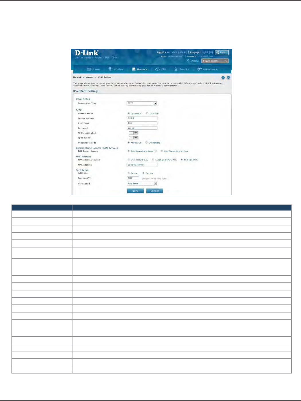
D-Link DSR-Series User Manual 33
Section 5 - Connect to the Internet
PPTP
Path: Network > Internet > WAN1 Settings
Select PPTP to enter the PPTP Internet settings supplied by your Internet Service Provider.
Field Description
Address Mode Select Dynamic IP or Static IP (IP settings supplied by your ISP).
Server Address Enter your PPTP server address.
User Name Enter your PPTP user name.
Password Enter your PPTP password.
MPPE Encryption Toggle to ON and select the level of MPPE encryption.
Split Tunnel Toggle to ON to use split tunnelling. This will allow you to connect to a VPN and Internet using the same
physical connection.
Reconnect Mode
Some ISPs may require you to pay for usage time. Select On Demand if this is the case. This will have the
router connect to the Internet only when you initiate an Internet connection. Select Always On to have the
router stay connected to the Internet.
IP Address If you selected Static IP, enter the IP address supplied by your ISP.
IP Subnet Mask If you selected Static IP, enter the subnet mask supplied by your ISP.
Gateway IP Address If you selected Static IP, enter the gateway IP address supplied by your ISP.
DNS Server Source Select either Get Dynamically from ISP or Use These DNS Servers to manually enter DNS servers.
Primary DNS Server If you selected “Use These DNS Servers”, enter the primary DNS server IP address.
Secondary DNS Server If you selected “Use These DNS Servers”, enter the secondary DNS server IP address.
MAC Address Source
Select Use Default MAC to use the MAC address from the WAN1 port to associate with your modem/ISP,
Clone your PC’s MAC to use the MAC address of the computer you are currently using to associate with your
modem/ISP, or Use this MAC to manually enter a MAC address.
MAC Address If you selected Use this MAC, enter the MAC address you want to associate with your ISP.
MTU Size Select to use the default MTU value (1500) or select Custom to enter your own value.
Custom MTU Enter a MTU value to optimize performance with your ISP.
Port Speed Select a value from the drop-down menu. The default value is Auto-Sense.
Save Click Save to save and activate your settings.
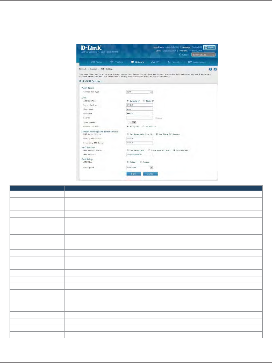
D-Link DSR-Series User Manual 34
Section 5 - Connect to the Internet
L2TP
Field Description
Address Mode Select Dynamic IP or Static IP (IP settings supplied by your ISP).
Server Address Enter your PPTP server address.
User Name Enter your PPTP user name.
Password Enter your PPTP password.
Secret Enter a shared secret if required.
Split Tunnel Toggle to ON to use split tunnelling. This will allow you to connect to a VPN and Internet using the same
physical connection.
Reconnect Mode
Some ISPs may require you to pay for usage time. Select On Demand if this is the case. This will have the
router connect to the Internet only when you initiate an Internet connection. Select Always On to have the
router stay connected to the Internet.
IP Address If you selected Static IP, enter the IP address supplied by your ISP.
IP Subnet Mask If you selected Static IP, enter the subnet mask supplied by your ISP.
Gateway IP Address If you selected Static IP, enter the gateway IP address supplied by your ISP.
DNS Server Source Select either Get Dynamically from ISP or Use These DNS Servers to manually enter DNS servers.
Primary DNS Server If you selected “Use These DNS Servers”, enter the primary DNS server IP address.
Secondary DNS Server If you selected “Use These DNS Servers”, enter the secondary DNS server IP address.
MAC Address Source
Select Use Default MAC to use the MAC address from the WAN1 port to associate with your modem/ISP,
Clone your PC’s MAC to use the MAC address of the computer you are currently using to associate with your
modem/ISP, or Use this MAC to manually enter a MAC address.
MAC Address If you selected Use this MAC, enter the MAC address you want to associate with your ISP.
MTU Size Select to use the default MTU value (1500) or select Custom to enter your own value.
Custom MTU Enter a MTU value to optimize performance with your ISP.
Port Speed Select a value from the drop-down menu. The default value is Auto-Sense.
Save Click Save to save and activate your settings.
Path: Network > Internet > WAN1 Settings
Select L2TP to enter the L2TP Internet settings supplied by your Internet Service Provider.
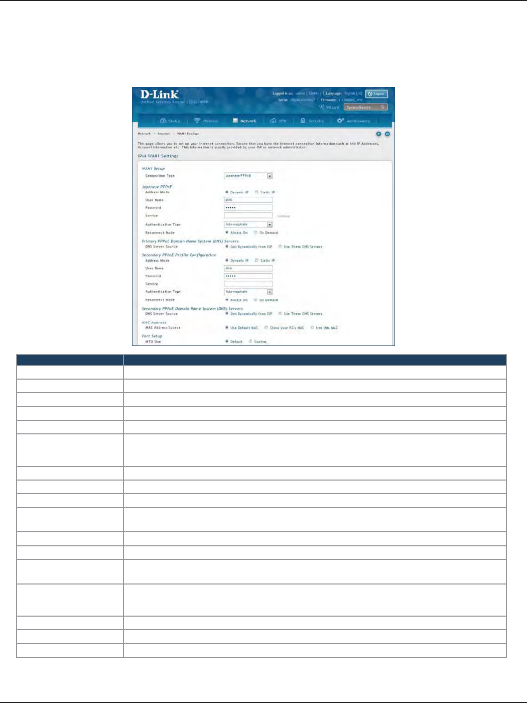
D-Link DSR-Series User Manual 35
Section 5 - Connect to the Internet
Japanese PPPoE
Path: Network > Internet > WAN1 Settings
Select Japanese PPPoE to enter the PPPoE Internet settings supplied by your Internet Service Provider.
Field Description
Address Mode Select Dynamic IP or Static IP (IP settings supplied by your ISP).
User Name Enter your PPPoE user name.
Password Enter your PPPoE password.
Service Enter if your ISP requires it.
Authentication Type Select the authentication type from the drop-down menu.
Reconnect Mode
Some ISPs may require you to pay for usage time. Select On Demand if this is the case. This will
have the router connect to the Internet only when you initiate an Internet connection. Select
Always On to have the router stay connected to the Internet.
IP Address If you selected Static IP, enter the IP address supplied by your ISP.
IP Subnet Mask If you selected Static IP, enter the subnet mask supplied by your ISP.
Gateway IP Address If you selected Static IP, enter the gateway IP address supplied by your ISP.
Primary PPPoE DNS
Servers
Select either Get Dynamically from ISP or Use These DNS Servers to manually enter DNS
servers.
Primary DNS Server If you selected “Use These DNS Servers”, enter the primary DNS server IP address.
Secondary DNS Server If you selected “Use These DNS Servers”, enter the secondary DNS server IP address.
Secondary PPPoE
Prole You may create a secondary PPPoE prole.
MAC Address Source
Select Use Default MAC to use the MAC address from the WAN1 port to associate with your
modem/ISP, Clone your PC’s MAC to use the MAC address of the computer you are currently
using to associate with your modem/ISP, or Use this MAC to manually enter a MAC address.
MAC Address If you selected Use this MAC, enter the MAC address you want to associate with your ISP.
Port Speed Select a value from the drop-down menu. The default value is Auto-Sense.
Save Click Save to save and activate your settings.
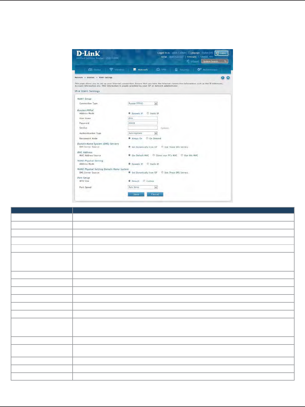
D-Link DSR-Series User Manual 36
Section 5 - Connect to the Internet
Russian PPPoE
Path: Network > Internet > WAN1 Settings
Select Russian PPPoE to enter the PPPoE Internet settings supplied by your Internet Service Provider.
Field Description
Address Mode Select Dynamic IP or Static IP (IP settings supplied by your ISP).
User Name Enter your PPPoE user name.
Password Enter your PPPoE password.
Service Enter if your ISP requires it.
Authentication Type Select the authentication type from the drop-down menu.
Reconnect Mode
Some ISPs may require you to pay for usage time. Select On Demand if this is the case. This will have
the router connect to the Internet only when you initiate an Internet connection. Select Always On
to have the router stay connected to the Internet.
IP Address If you selected Static IP, enter the IP address supplied by your ISP.
IP Subnet Mask If you selected Static IP, enter the subnet mask supplied by your ISP.
Gateway IP Address If you selected Static IP, enter the gateway IP address supplied by your ISP.
DNS Server Source Select either Get Dynamically from ISP or Use These DNS Servers to manually enter DNS servers.
Primary DNS Server If you selected “Use These DNS Servers”, enter the primary DNS server IP address.
Secondary DNS Server If you selected “Use These DNS Servers”, enter the secondary DNS server IP address.
MAC Address Source
Select Use Default MAC to use the MAC address from the WAN1 port to associate with your
modem/ISP, Clone your PC’s MAC to use the MAC address of the computer you are currently using
to associate with your modem/ISP, or Use this MAC to manually enter a MAC address.
MAC Address If you selected Use this MAC, enter the MAC address you want to associate with your ISP.
WAN2 Physical Setting Select Dynamic IP or Static IP (IP settings supplied by your ISP). If you select Static IP, enter the IP
settings supplied by your ISP.
WAN2 Physical DNS Select either Get Dynamically from ISP or Use These DNS Servers to manually enter DNS servers.
Port Speed Select a value from the drop-down menu. The default value is Auto-Sense.
Save Click Save to save and activate your settings.
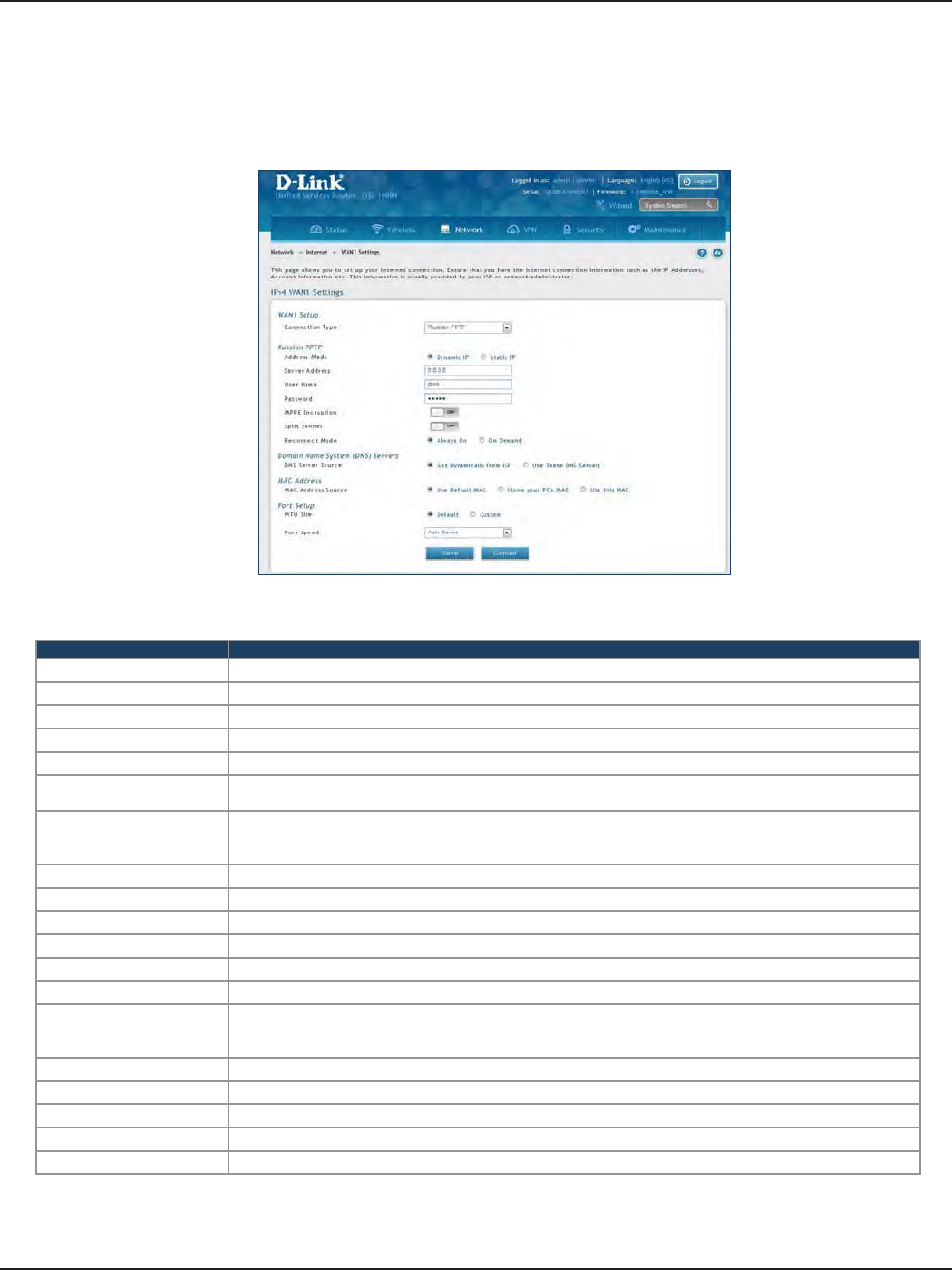
D-Link DSR-Series User Manual 37
Section 5 - Connect to the Internet
Russian PPTP
Field Description
Address Mode Select Dynamic IP or Static IP (IP settings supplied by your ISP).
Server Address Enter your PPTP server address.
User Name Enter your PPTP user name.
Password Enter your PPTP password.
MPPE Encryption Toggle to ON and select the level of MPPE encryption.
Split Tunnel Toggle to ON to use split tunnelling. This will allow you to connect to a VPN and Internet using the same
physical connection.
Reconnect Mode
Some ISPs may require you to pay for usage time. Select On Demand if this is the case. This will have the
router connect to the Internet only when you initiate an Internet connection. Select Always On to have the
router stay connected to the Internet.
IP Address If you selected Static IP, enter the IP address supplied by your ISP.
IP Subnet Mask If you selected Static IP, enter the subnet mask supplied by your ISP.
Gateway IP Address If you selected Static IP, enter the gateway IP address supplied by your ISP.
DNS Server Source Select either Get Dynamically from ISP or Use These DNS Servers to manually enter DNS servers.
Primary DNS Server If you selected “Use These DNS Servers”, enter the primary DNS server IP address.
Secondary DNS Server If you selected “Use These DNS Servers”, enter the secondary DNS server IP address.
MAC Address Source
Select Use Default MAC to use the MAC address from the WAN1 port to associate with your modem/ISP,
Clone your PC’s MAC to use the MAC address of the computer you are currently using to associate with your
modem/ISP, or Use this MAC to manually enter a MAC address.
MAC Address If you selected Use this MAC, enter the MAC address you want to associate with your ISP.
MTU Size Select to use the default MTU value (1500) or select Custom to enter your own value.
Custom MTU Enter a MTU value to optimize performance with your ISP.
Port Speed Select a value from the drop-down menu. The default value is Auto-Sense.
Save Click Save to save and activate your settings.
Path: Network > Internet > WAN1 Settings
Select Russian PPTP to enter the PPTP Internet settings supplied by your Internet Service Provider.
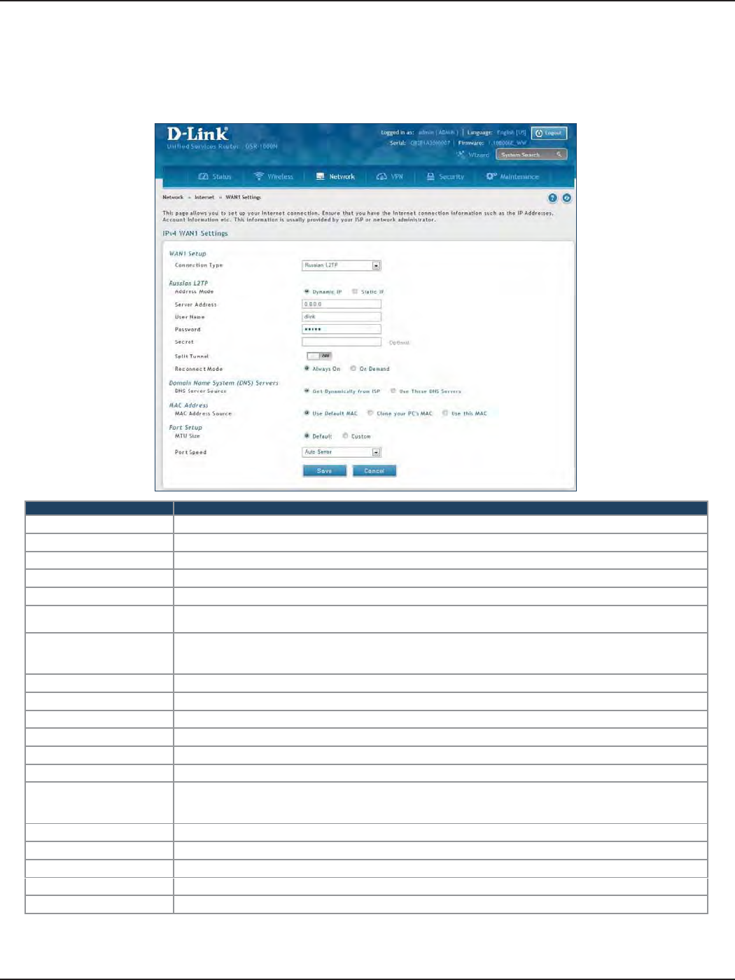
D-Link DSR-Series User Manual 38
Section 5 - Connect to the Internet
Russian L2TP
Path: Network > Internet > WAN1 Settings
Select Russian L2TP to enter the L2TP Internet settings supplied by your Internet Service Provider.
Field Description
Address Mode Select Dynamic IP or Static IP (IP settings supplied by your ISP).
Server Address Enter your PPTP server address.
User Name Enter your PPTP user name.
Password Enter your PPTP password.
Secret Enter a shared secret if required.
Split Tunnel Toggle to ON to use split tunnelling. This will allow you to connect to a VPN and Internet using the same
physical connection.
Reconnect Mode
Some ISPs may require you to pay for usage time. Select On Demand if this is the case. This will have the
router connect to the Internet only when you initiate an Internet connection. Select Always On to have the
router stay connected to the Internet.
IP Address If you selected Static IP, enter the IP address supplied by your ISP.
IP Subnet Mask If you selected Static IP, enter the subnet mask supplied by your ISP.
Gateway IP Address If you selected Static IP, enter the gateway IP address supplied by your ISP.
DNS Server Source Select either Get Dynamically from ISP or Use These DNS Servers to manually enter DNS servers.
Primary DNS Server If you selected “Use These DNS Servers”, enter the primary DNS server IP address.
Secondary DNS Server If you selected “Use These DNS Servers”, enter the secondary DNS server IP address.
MAC Address Source
Select Use Default MAC to use the MAC address from the WAN1 port to associate with your modem/ISP,
Clone your PC’s MAC to use the MAC address of the computer you are currently using to associate with your
modem/ISP, or Use this MAC to manually enter a MAC address.
MAC Address If you selected Use this MAC, enter the MAC address you want to associate with your ISP.
MTU Size Select to use the default MTU value (1500) or select Custom to enter your own value.
Custom MTU Enter a MTU value to optimize performance with your ISP.
Port Speed Select a value from the drop-down menu. The default value is Auto-Sense.
Save Click Save to save and activate your settings.
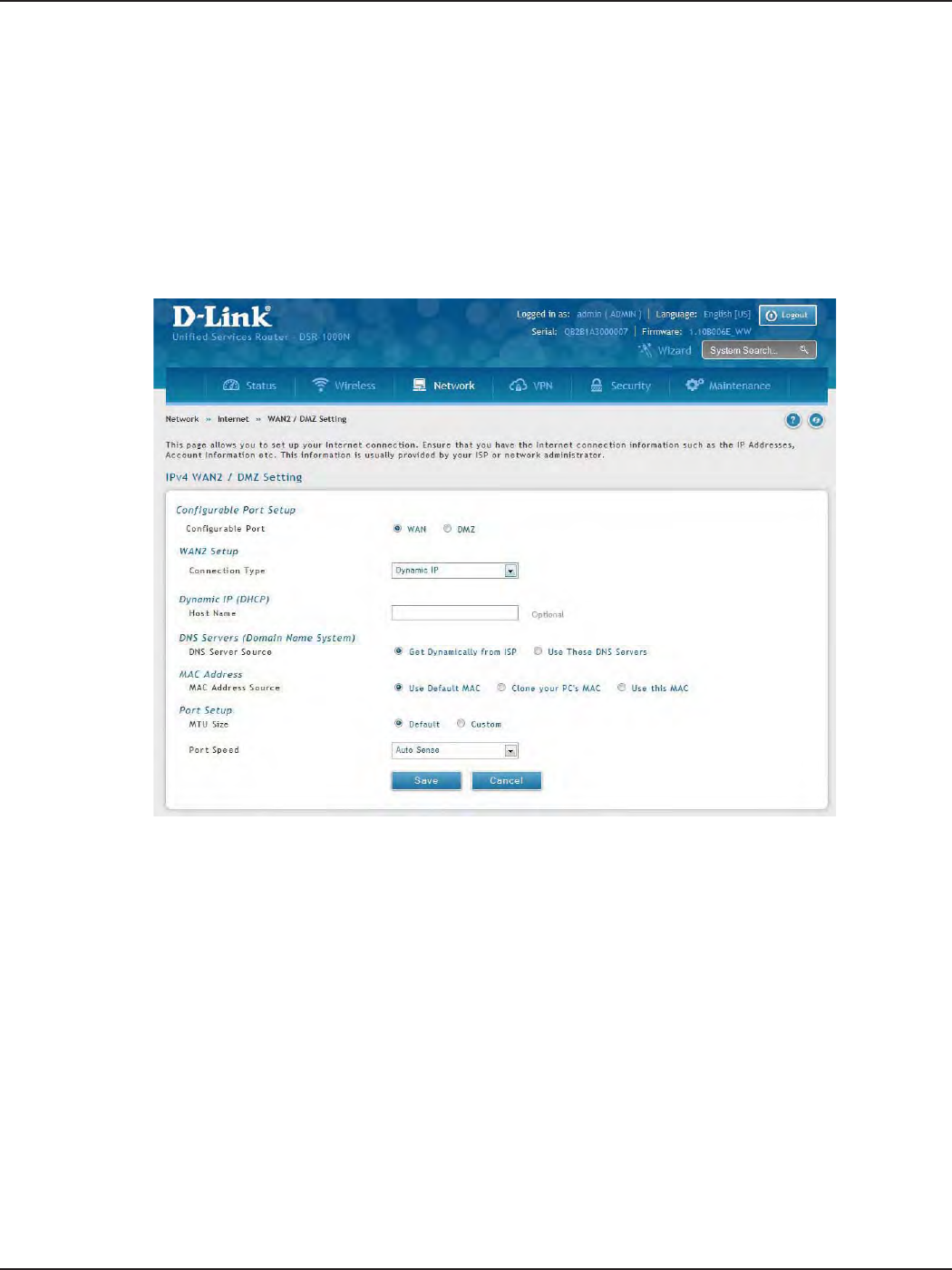
D-Link DSR-Series User Manual 39
Section 5 - Connect to the Internet
WAN2 Settings
WAN
Path: Network > Internet > WAN2 Settings
Select WAN and select the Internet connection type. Please refer to the previous pages (41-49) for more
information. If you want to set WAN2 port to DMZ, skip to the next page.
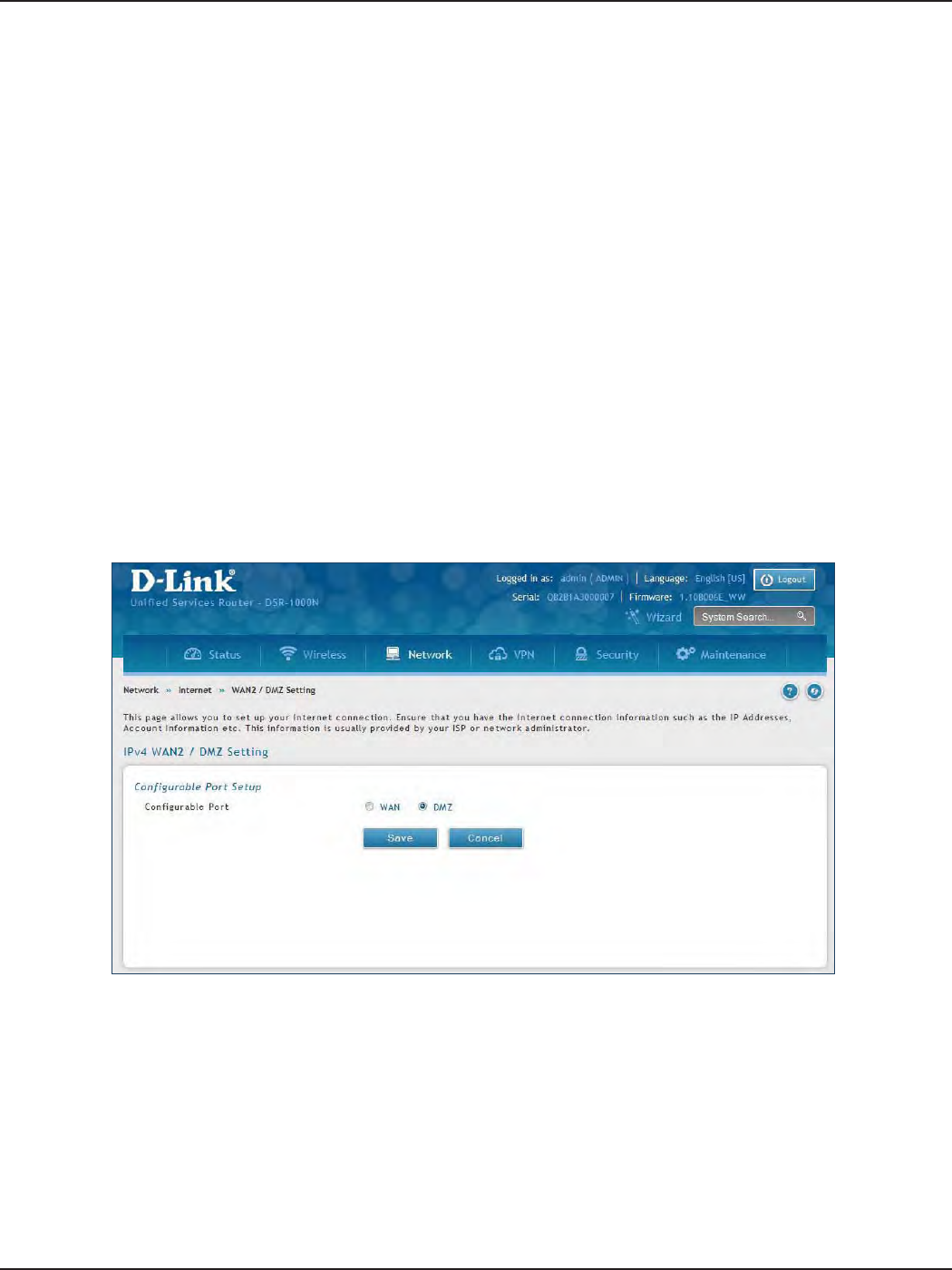
D-Link DSR-Series User Manual 40
Section 5 - Connect to the Internet
DMZ
This router supports one of the physical ports to be congured as a secondary WAN Ethernet port or a dedicated
DMZ port. A DMZ is a sub network that is open to the public but behind the rewall. The DMZ adds an additional
layer of security to the LAN, as specic services/ports that are exposed to the internet on the DMZ do not have
to be exposed on the LAN. It is recommended that hosts that must be exposed to the internet (such as web or
email servers) be placed in the DMZ network.
Firewall rules can be allowed to permit access specic services/ports to the DMZ from both the LAN or WAN. In
the event of an attack to any of the DMZ nodes, the LAN is not necessarily vulnerable as well.
DMZ conguration is identical to the LAN conguration. There are no restrictions on the IP address or subnet
assigned to the DMZ port, other than the fact that it cannot be identical to the IP address given to the LAN
interface of this gateway.
Note: For the DSR-500N and 1000N, in order to congure a DMZ port, the router’s congurable port must be set to
DMZ in the Network > Internet > DMZ Settings page.
1. Click Network > Internet > WAN2 / DMZ Settings.
2. Select DMZ and click Save.
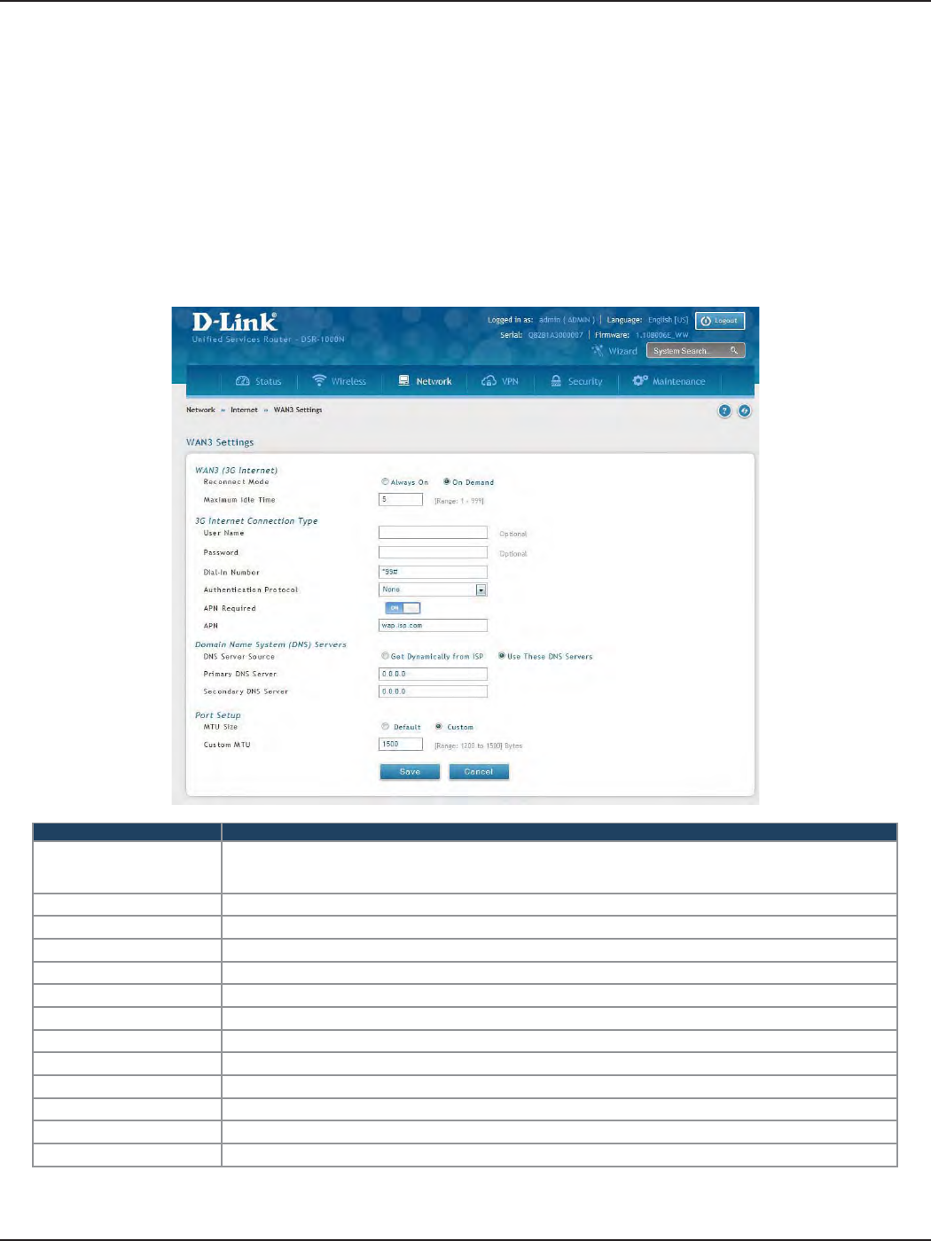
D-Link DSR-Series User Manual 41
Section 5 - Connect to the Internet
WAN3 (3G Internet)
Path: Network > Internet > WAN3 Settings
This router supports the use of 3G Internet access. Cellular 3G internet access is available on WAN3 via a 3G
USB modem for DSR-1000 and DSR-1000N. The cellular ISP that provides the 3G data plan will provide the
authentication requirements to establish a connection. The dial Number and APN are specic to the cellular
carriers. Once the connection type settings are congured and saved, navigate to the WAN status page (Setup >
Internet Settings > WAN3 Status) and Enable the WAN3 link to establish the 3G connection.
Note: A 3G USB modem can be congured as the third WAN in DSR-1000 and DSR- 1000N.
Field Description
Reconnect Mode
Some ISPs may require you to pay for usage time. Select On Demand if this is the case. This will have the
router connect to the Internet only when you initiate an Internet connection. Select Always On to have the
router stay connected to the Internet.
Maximum Idle Time Enter the idle time in minutes before the router disconnects from the Internet (On Demand only).
User Name Enter your 3G account user name.
Password Enter your 3G account password.
Dial-in Number Enter the phone number to access your Internet.
Authentication Protocol Select one of following protocols from the drop-down menu: None, PAP or CHAP.
APN Required Toggle to ON if your ISP requires APN to connect.
APN Enter the APN (Access Point Name) provided by the ISP.
DNS Server Source Select either Get Dynamically from ISP or Use These DNS Servers to manually enter DNS servers.
Primary DNS Server If you selected “Use These DNS Servers”, enter the primary DNS server IP address.
Secondary DNS Server If you selected “Use These DNS Servers”, enter the secondary DNS server IP address.
MTU Size Select to use the default MTU value (1500) or select Custom to enter your own value.
Custom MTU Enter a MTU value to optimize performance with your ISP.
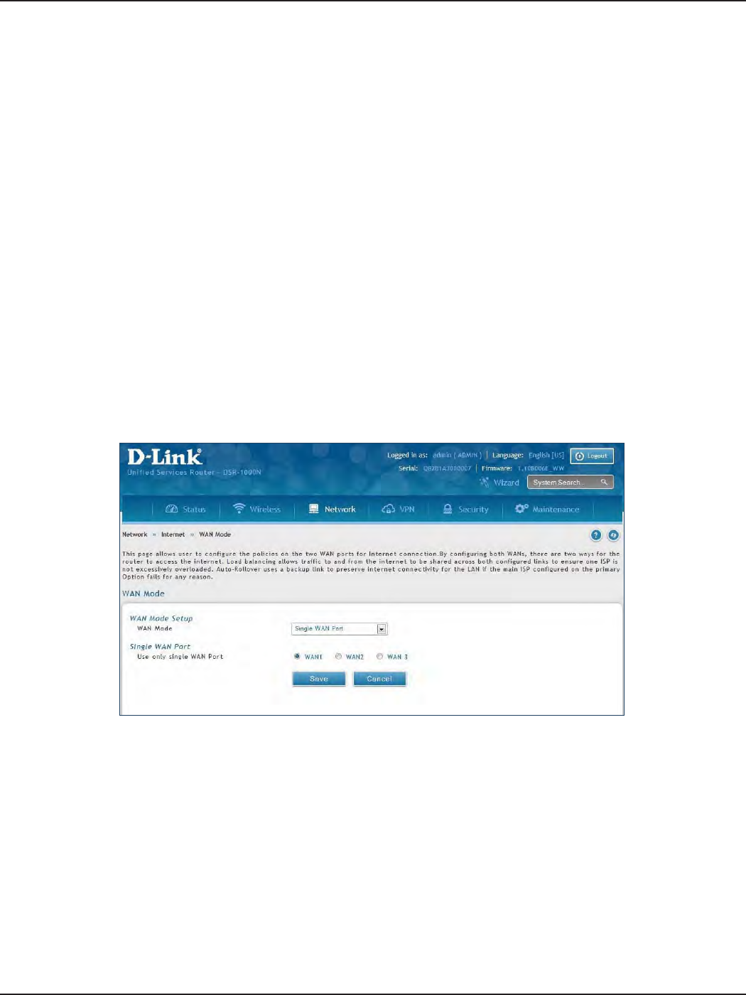
D-Link DSR-Series User Manual 42
Section 5 - Connect to the Internet
WAN Mode
Single WAN Port
Path: Network > Internet > WAN Mode
This router supports multiple WAN links. This allows you to take advantage of failover and load balancing
features to ensure certain internet dependent services are prioritized in the event of unstable WAN connectivity
on one of the ports.
To use Auto Failover or Load Balancing, WAN link failure detection must be congured. This involves accessing
DNS servers on the internet or ping to an internet address (user dened). If required, you can congure the
number of retry attempts when the link seems to be disconnected or the threshold of failures that determines
if a WAN port is down.
If you do not want to use Auto Failover or Load Balancing, select Single WAN Port from the WAN Mode drop-down
menu and select the WAN port you want to set. Click Save.
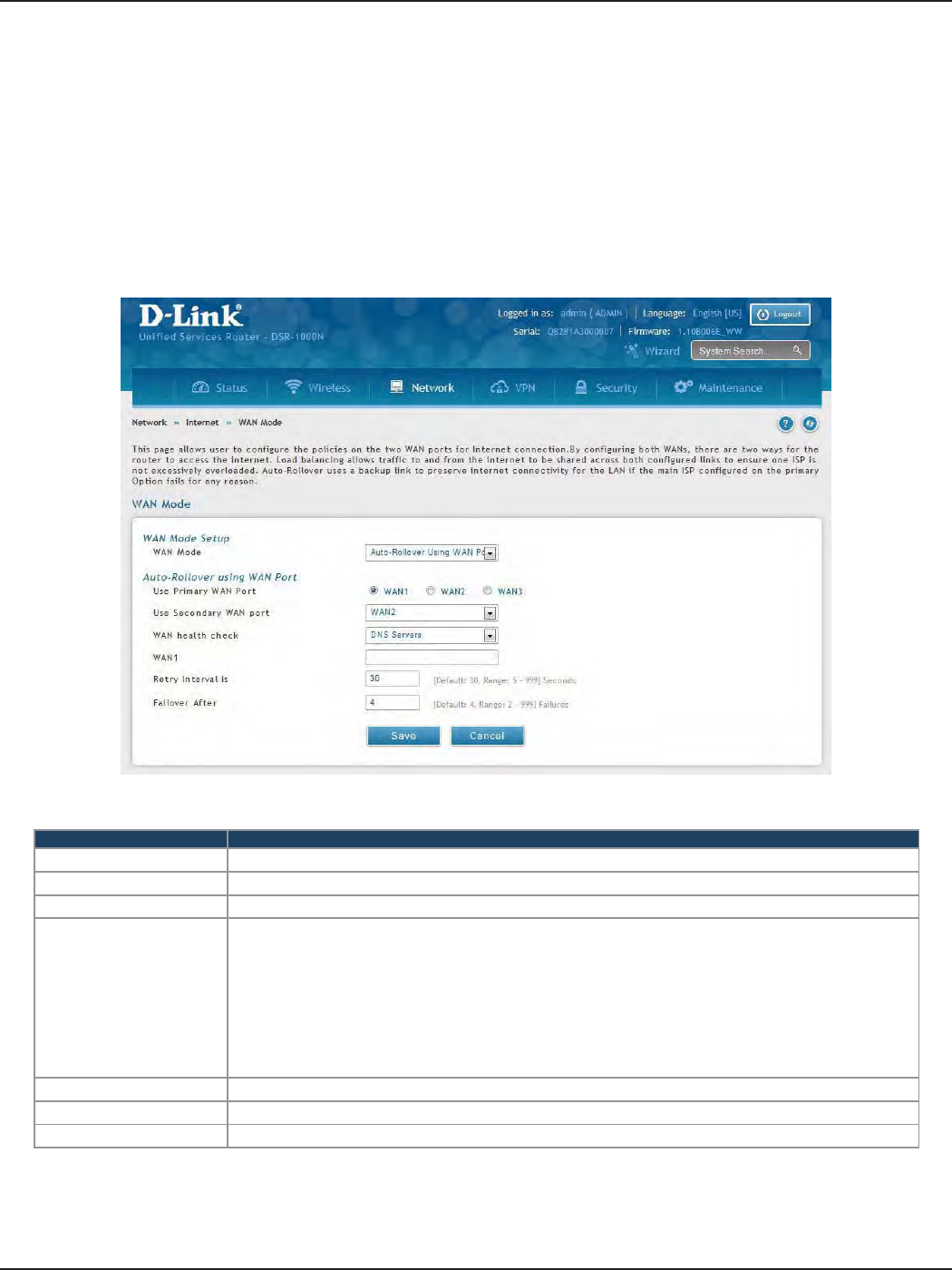
D-Link DSR-Series User Manual 43
Section 5 - Connect to the Internet
Auto-Rollover using WAN IP
In this mode one of your WAN ports is assigned as the primary internet link for all internet trac and the
secondary WAN port is used for redundancy in case the primary link goes down for any reason. Both WAN ports
(primary and secondary) must be congured to connect to the respective ISP’s before enabling this feature. The
secondary WAN port will remain unconnected until a failure is detected on the primary link (either port can be
assigned as the primary). In the event of a failure on the primary port, all internet trac will be rolled over to
the backup port. When congured in Auto-Failover mode, the link status of the primary WAN port is checked at
regular intervals as dened by the failure detection settings.
Field Description
WAN Mode Select Auto-Rollover Using WAN IP from the drop-down menu.
Use Primary WAN Port Select which WAN port is the primary.
Use Secondary WAN Port Select which port to use if the primary port fails.
WAN Health Check
• DNS lookup using WAN DNS Servers: DNS Lookup of the DNS Servers of the primary link is used to
detect primary WAN connectivity.
• DNS lookup using DNS Servers: DNS Lookup of the custom DNS Servers can be specied to check the
connectivity of the primary link.
• Ping these IP addresses: These IP’s will be pinged at regular intervals to check the connectivity of the
primary link.
• Retry Interval is: The number tells the router how often it should run the above congured failure
detection method.
• Failover after: This sets the number of retries after which failover is initiated.
WAN1/WAN2/WAN3 Enter the DNS server or IP address to ping.
Retry Interval Enter the time in seconds to initiate the WAN health check. Default is every 30 seconds.
Failover After Enter the number of failures before the router will enable the failover process.
Note: The DSR-1000, DSR-1000N, DSR-500, DSR-500N, DSR-250, DSR-250N, DSR-150, and DSR-150N routers support
3G USB Modem as a failover link when the internet access is lost.
1. Click Network > Internet > WAN Mode.
2. Complete the elds from the table below and click Save.

D-Link DSR-Series User Manual 44
Section 5 - Connect to the Internet
Load Balancing
Path: Network > Internet > WAN Mode
This feature allows you to use multiple WAN links (and presumably multiple ISP’s) simultaneously. After
conguring more than one WAN port, the load balancing option is available to carry trac over more than one
link. Protocol bindings are used to segregate and assign services over one WAN port in order to manage internet
ow. The congured failure detection method is used at regular intervals on all congured WAN ports when in
Load Balancing mode.
This router currently supports three algorithms for Load Balancing:
Round Robin: This algorithm is particularly useful when the connection speed of one WAN port greatly
diers from another. In this case you can dene protocol bindings to route low-latency services (such
as VOIP) over the higher -speed link and let low-volume background trac (such as SMTP) go over the
lower speed link. Protocol binding is explained in next section.
Spillover: If Spillover method is selected, the primary WAN acts as a dedicated link until a dened
bandwidth threshold are reached. After this, the secondary WAN will be used for new connections.
Inbound connections on the secondary WAN are permitted with this mode, as the spillover logic governs
outbound connections moving from the primary to secondary WAN. You can congure spillover mode
by using following options:
• Load Tolerance: It is the percentage of bandwidth after which the router switches to
secondary WAN.
• Max Bandwidth: This sets the maximum bandwidth tolerable by the primary WAN for
outbound trac.
If the link bandwidth of outbound trac goes above the load tolerance value of max bandwidth, the
router will spillover the next connections to secondary WAN.
For example, if the maximum bandwidth of primary WAN is 1Kbps and the load tolerance is set to 70. Now
every time a new connection is established the bandwidth increases. After a certain number of connections say
bandwidth reached 70% of 1Kbps, the new outbound connections will be spilled over to secondary WAN. The
maximum value of load tolerance is 80% and the minimum is 20%.
Note: The DSR-1000, DSR-1000N, DSR-500, and DSR-500N routers support the trac load balancing between physical
WAN port and a 3G USB Modem.
Load balancing is particularly useful when the connection speed of one WAN port greatly diers from another.
In this case you can dene protocol bindings to route low-latency services (such as VOIP) over the higher-speed
link and let low-volume background trac (such as SMTP) go over the lower speed link.
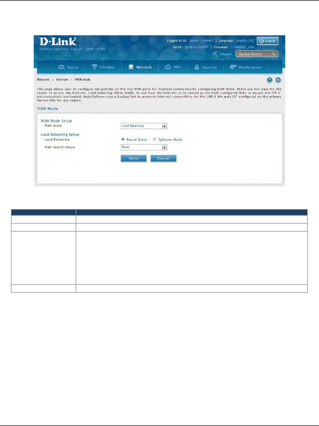
D-Link DSR-Series User Manual 45
Section 5 - Connect to the Internet
Field Description
WAN Mode Select Load Balancing from the drop-down menu.
Load Balance Select Round Robin.
WAN Health Check
• DNS lookup using WAN DNS Servers: DNS Lookup of the DNS Servers of the primary link is used to
detect primary WAN connectivity.
• DNS lookup using DNS Servers: DNS Lookup of the custom DNS Servers can be specied to check the
connectivity of the primary link.
• Ping these IP addresses: These IP’s will be pinged at regular intervals to check the connectivity of the
primary link.
• Retry Interval is: The number tells the router how often it should run the above congured failure
detection method.
• Failover after: This sets the number of retries after which failover is initiated.
Save Click to save and activate your settings.
Round Robin
1. Click Network > Internet > WAN Mode.
2. Complete the elds from the table below and click Save.
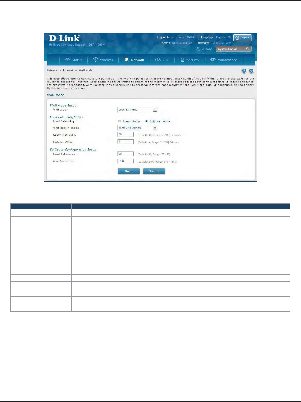
D-Link DSR-Series User Manual 46
Section 5 - Connect to the Internet
Field Description
WAN Mode Select Load Balancing from the drop-down menu.
Load Balance Select Spillover Mode.
WAN Health Check
• DNS lookup using WAN DNS Servers: DNS Lookup of the DNS Servers of the primary link is used to
detect primary WAN connectivity.
• DNS lookup using DNS Servers: DNS Lookup of the custom DNS Servers can be specied to check the
connectivity of the primary link.
• Ping these IP addresses: These IP’s will be pinged at regular intervals to check the connectivity of the
primary link.
• Retry Interval is: The number tells the router how often it should run the above congured failure
detection method.
• Failover after: This sets the number of retries after which failover is initiated.
Retry Interval is Enter the time in seconds to initiate the WAN health check. Default is every 30 seconds.
Failover After Enter the number of failures before the router will enable the failover process.
Load Tolerance Enter the percentage of bandwidth after which the router switches to the secondary WAN.
Max Bandwidth This sets the maximum bandwidth tolerable by the primary WAN for outbound trac.
Save Click to save and activate your settings.
Spillover
1. Click Network > Internet > WAN Mode.
2. Complete the elds from the table below and click Save.
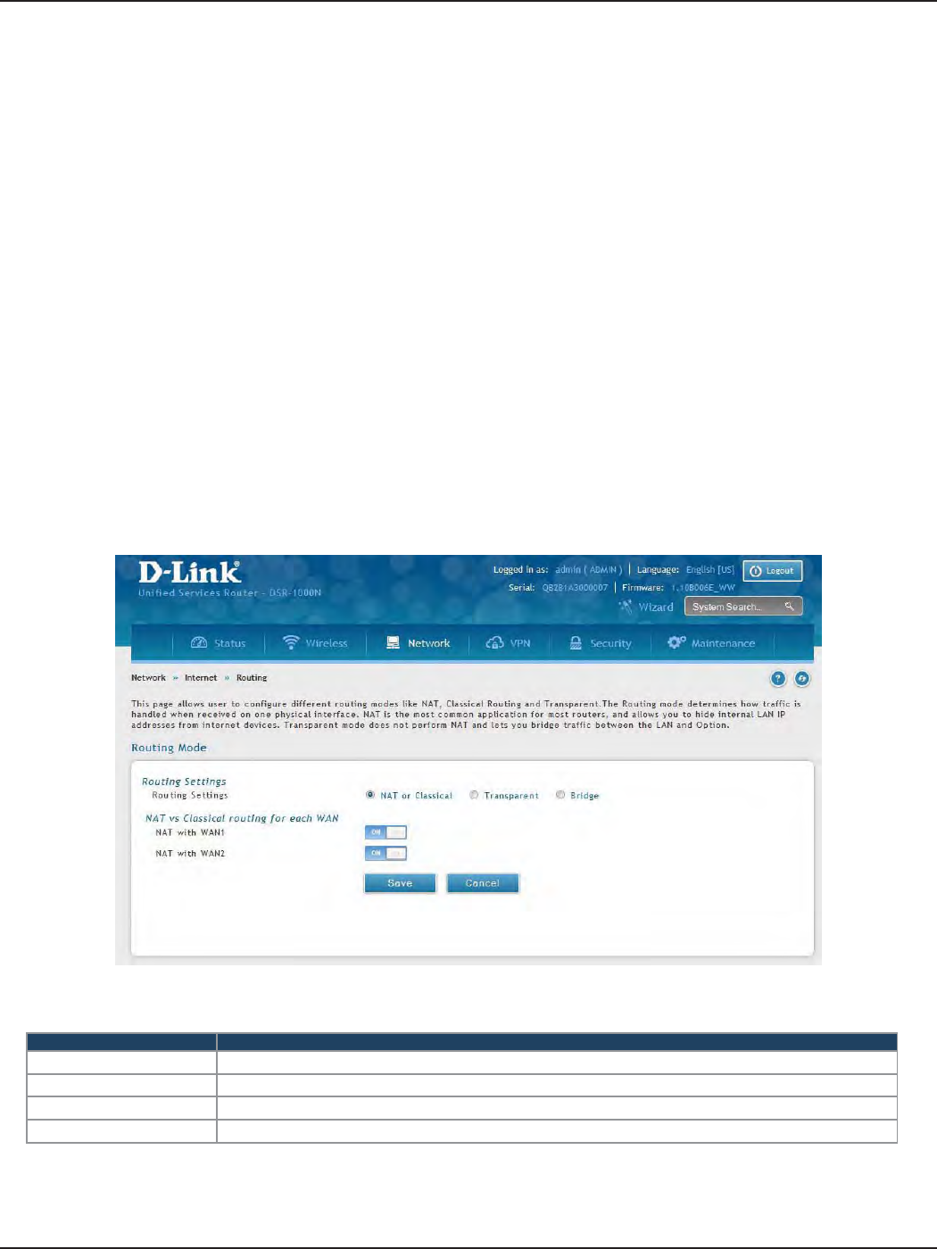
D-Link DSR-Series User Manual 47
Section 5 - Connect to the Internet
Routing Mode
Routing between the LAN and WAN will impact the way this router handles trac that is received on any of
its physical interfaces. The routing mode of the gateway is core to the behavior of the trac ow between the
secure LAN and the internet.
NAT or Classical
Field Description
Routing Settings Select NAT or Classical.
NAT with WAN1 Toggle to ON to use NAT with WAN1 or OFF for classical.
NAT with WAN2 Toggle to ON to use NAT with WAN2 or OFF for classical.
Save Click to save and activate your settings.
Path: Network > Internet > Routing Mode
With classical routing, devices on the LAN can be directly accessed from the internet with their public IP addresses
(assuming appropriate rewall settings are congured). If your ISP has assigned an IP address for each of the
computers/devices that you use, select Classical.
NAT is a technique which allows several computers and devices on your local network to share an Internet
connection. The computers on the LAN use a “private” IP address range while the WAN port on the router is
congured with a single “public” IP address. Along with connection sharing, NAT also hides internal IP addresses
from the computers on the Internet. NAT is required if your ISP has assigned only one IP address to you. The
computers/devices that connect through the router will need to be assigned IP addresses from a private subnet.
1. Click Network > Internet > Routing Mode.
2. Complete the elds from the table below and click Save.
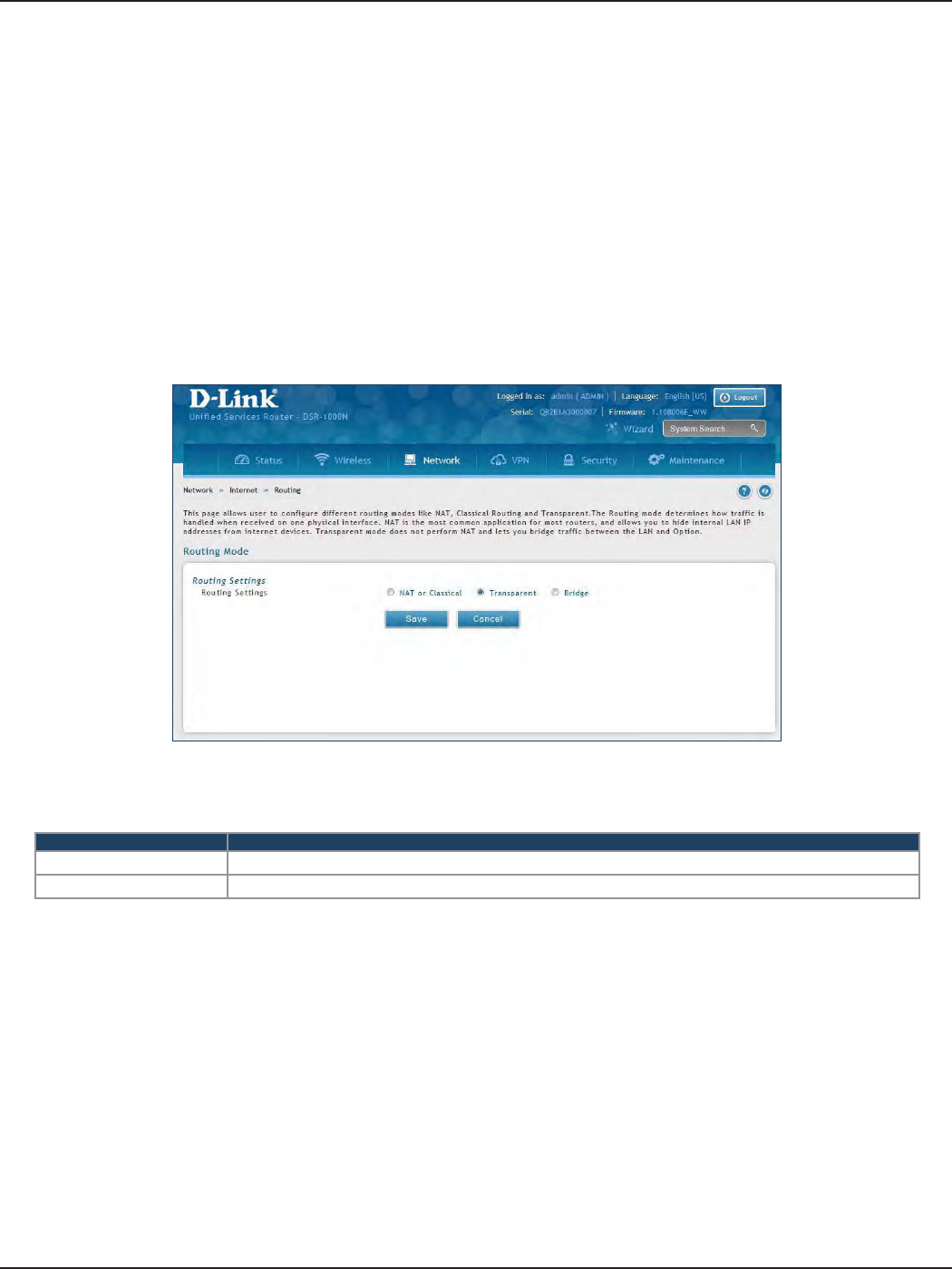
D-Link DSR-Series User Manual 48
Section 5 - Connect to the Internet
Transparent
Field Description
Routing Settings Select Transparent.
Save Click to save and activate your settings.
When Transparent Routing Mode is enabled, NAT is not performed on trac between the LAN and WAN
interfaces. Broadcast and multicast packets that arrive on the LAN interface are switched to the WAN and vice
versa, if they do not get ltered by rewall or VPN policies. To maintain the LAN and WAN in the same broadcast
domain select Transparent mode, which allows bridging of trac from LAN to WAN and vice versa, except
for router-terminated trac and other management trac. All DSR features (such as 3G modem support) are
supported in transparent mode assuming the LAN and WAN are congured to be in the same broadcast domain.
Note: NAT routing has a feature called “NAT Hair -pinning” that allows internal network users on the LAN and DMZ to
access internal servers (e.g., an internal FTP server) using their externally-known domain name. This is also referred to as
“NAT loopback” since LAN generated trac is redirected through the rewall to reach LAN servers by their external name.
1. Click Network > Internet > Routing.
2. Complete the elds from the table below and click Save.
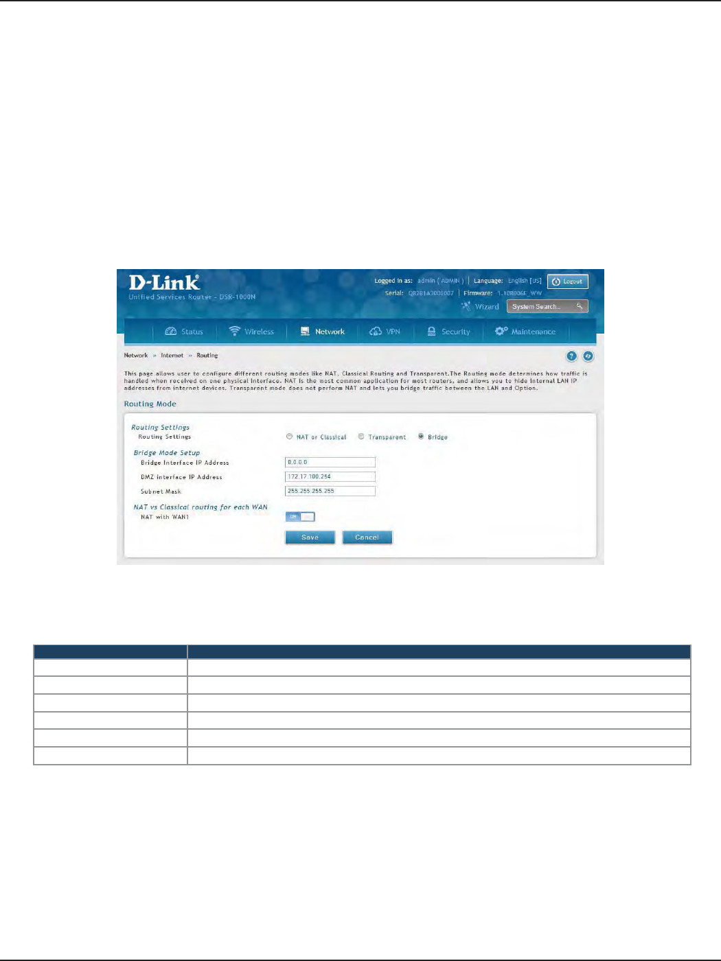
D-Link DSR-Series User Manual 49
Section 5 - Connect to the Internet
Bridge
Field Description
Routing Settings Select Bridge.
Bridge Interface IP Address Enter the bridge interface IP address.
DMZ Interface IP Address Enter the DMZ interface IP address.
Subnet Mask Enter the subnet mask.
NAT with WAN1 Toggle ON to turn NAT on WAN1 or OFF for classical.
Save Click to save and activate your settings.
When Bridge Mode routing is enabled, the rst physical LAN port and secondary WAN/DMZ (port 2) interfaces
are bridged together at Layer 2, creating an aggregate network. The other LAN ports and the primary WAN
(WAN1) are not part of this bridge, and the router asks as a NAT device for these other ports. With Bridge mode
for the LAN port 1 and WAN2/DMZ interfaces, L2 and L3 broadcast trac as well as ARP / RARP packets are
passed through. When WAN2 receives tagged trac the tag information will be removed before the packet is
forwarded to the LAN port 1 interface.
Note: Bridge mode option is available on DSR-500 / 500N / 1000 / 1000N routers only.
1. Click Network > Internet > Routing.
2. Complete the elds from the table below and click Save.
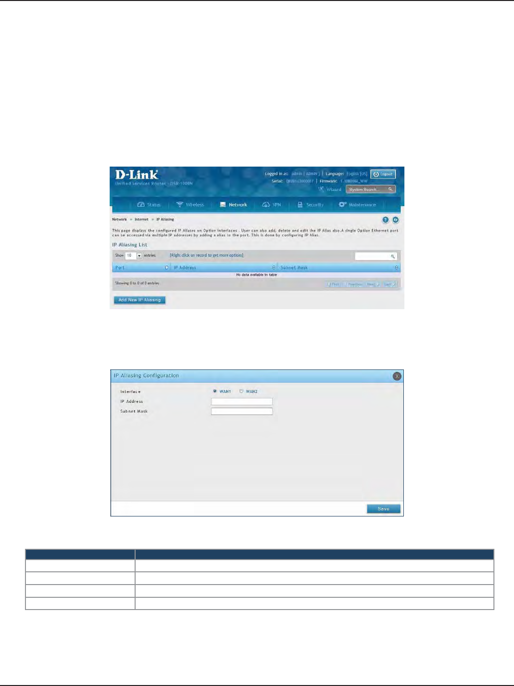
D-Link DSR-Series User Manual 50
Section 5 - Connect to the Internet
IP Aliasing
Path: Network > Internet > IP Aliasing
A single WAN Ethernet port can be accessed via multiple IP addresses by adding an alias to the port. This is done
by conguring an IP Alias address. To edit or delete any existing aliases, right-click the alias and select either Edit
or Delete.
Field Description
Interface Select either WAN1 or WAN2.
IP Address Enter an alias IP address for the WAN interface you selected.
Subnet Mask Enter a subnet mask for the WAN interface you selected.
Save Click to save and activate your settings.
To create a new alias:
1. Click Network > Internet > IP Aliasing.
2. Click Add New IP Aliasing.
3. Enter the following information and click Save.
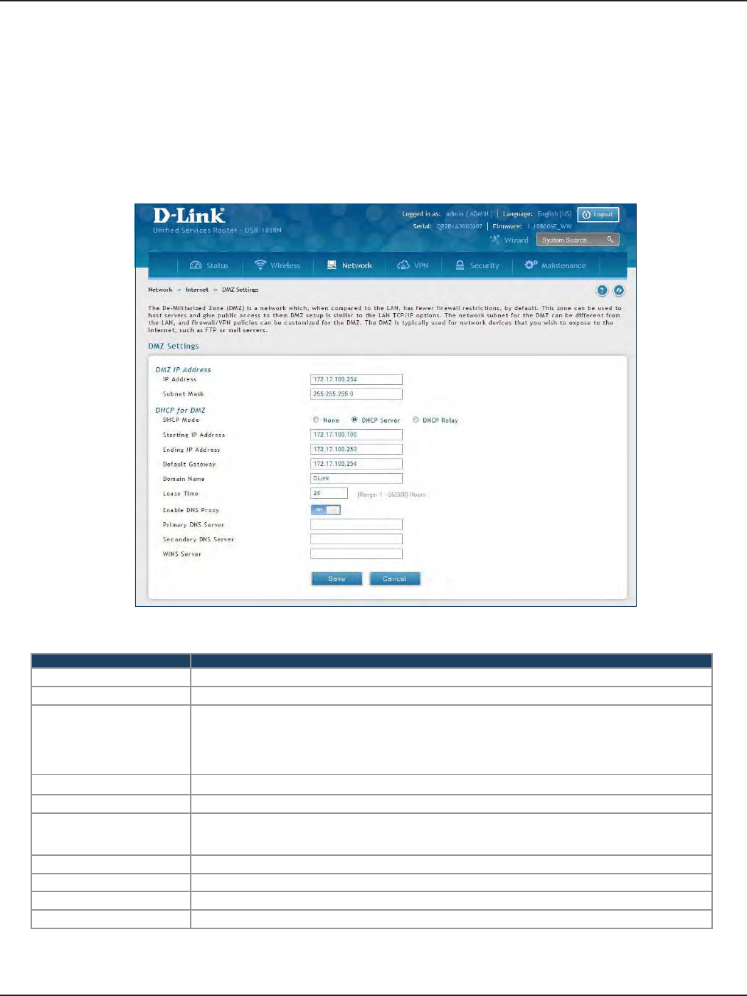
D-Link DSR-Series User Manual 51
Section 5 - Connect to the Internet
Field Description
IP Address Enter an IP address for the DMZ interface.
Subnet Mask Enter the subnet mask for the DMZ interface.
DHCP Mode
Select one of the following modes:
• None - Turns o DHCP.
• DHCP Server (default) - The router will act as the DHCP server on your network.
• DHCP Relay - DHCP clients on your network will receive IP address leases from a DHCP server on a
dierent subnet.
DHCP Server Refer to “DHCP Server” on page 19 for more information.
DHCP Relay Refer to “DHCP Relay” on page 20 for more information.
Enable DNS Proxy
Toggle to On to manually enter DNS and/or WINS server IP address(es). If set to O, your router’s LAN
IP address will be assigned the DNS server to your clients and the router will get the DNS information
from your ISP.
Primary DNS Server If DNS Proxy is set to ON, enter the primary DNS server IP address.
Secondary DNS Server If DNS Proxy is set to ON, enter the secondary DNS server IP address.
WINS Server If DNS Proxy is set to ON, enter the WINS server IP address.
Save Click to save and activate your settings.
DMZ Settings
Path: Network > Internet > DMZ Settings
If you set WAN2 port to DMZ, you will need to congure the port here.
To congure the DMZ Settings:
1. Click Network > Internet > DMZ Settings.
2. Complete the elds from the table below and click Save.
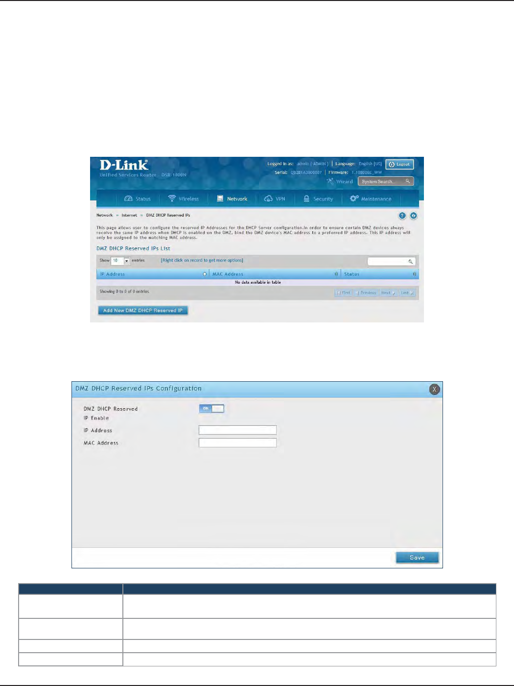
D-Link DSR-Series User Manual 52
Section 5 - Connect to the Internet
The router’s DHCP server can assign IP settings to your DMZ clients on your network by adding a client’s MAC
address and the IP address to be assigned. Whenever the router receives a request from a client, the MAC address
of that client is compared with the MAC address list present in the database. If an IP address is already assigned
to that computer or device in the database, the customized IP address is congured otherwise an IP address is
assigned to the client automatically from the DMZ DHCP pool.
To create DHCP reservations:
1. Click Network > Internet > DMZ LAN DHCP Reserved IPs.
2. Click Add New DMZ DHCP Reserved IP.
3. Enter the following information and click Save.
Field Description
DMZ DHCP Reserved IP
Enable Toggle to ON to enable this reservation.
IP Address Enter the IP address you want to assign to this device. Note that this IP address must be in the
same range as the starting/ending IP address under DHCP Settings.
MAC Address Enter the MAC address of this device (xx:xx:xx:xx:xx:xx format).
Save Click Save to save your reservation.
DMZ LAN DHCP Reserved IPs
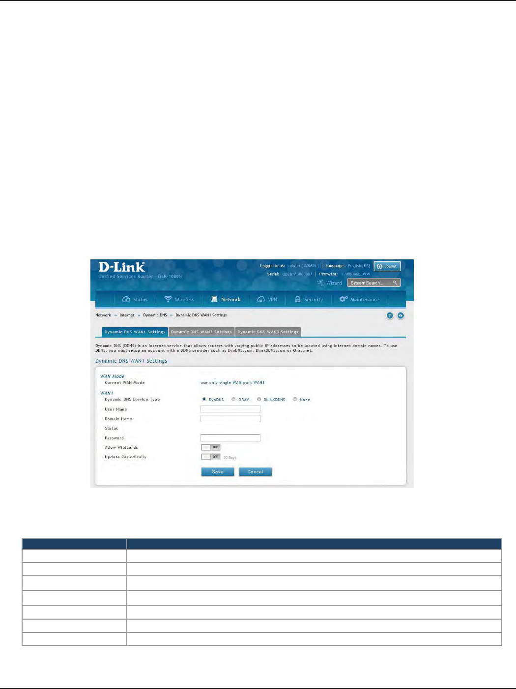
D-Link DSR-Series User Manual 53
Section 5 - Connect to the Internet
Dynamic DNS Settings
Path: Network > Internet > Dynamic DNS
Dynamic DNS (DDNS) is an Internet service that allows routers with varying public IP addresses to be located
using Internet domain names. To use DDNS, you must setup an account with a DDNS provider such as DynDNS.
org, D-Link DDNS, or Oray.net.
Each congured WAN can have a dierent DDNS service if required. Once congured, the router will update
DDNS services changes in the WAN IP address so that features that are dependent on accessing the router’s WAN
via FQDN will be directed to the correct IP address. When you set up an account with a DDNS service, the host
and domain name, username, password and wildcard support will be provided by the account provider.
To congure DDNS:
1. Click Network > Internet > Dynamic DNS
2. Click the tab on top to select which WAN port you want to congure DDNS to.
3. Next to Dynamic DNS Service Type, select your DDNS service.
4. Enter the following information and click Save. The information below is for DynDNS. Other services
will have similar elds.
Field Description
User Name Enter your DDNS user name.
Domain Name Enter the domain name.
Password Enter your DDNS password.
Status Displays the current connection status.
Allow Wildcards Toggle to ON to allow wildcards.
Update Periodically Toggle to ON to set a forced update.
Save Click Save to save your reservation.
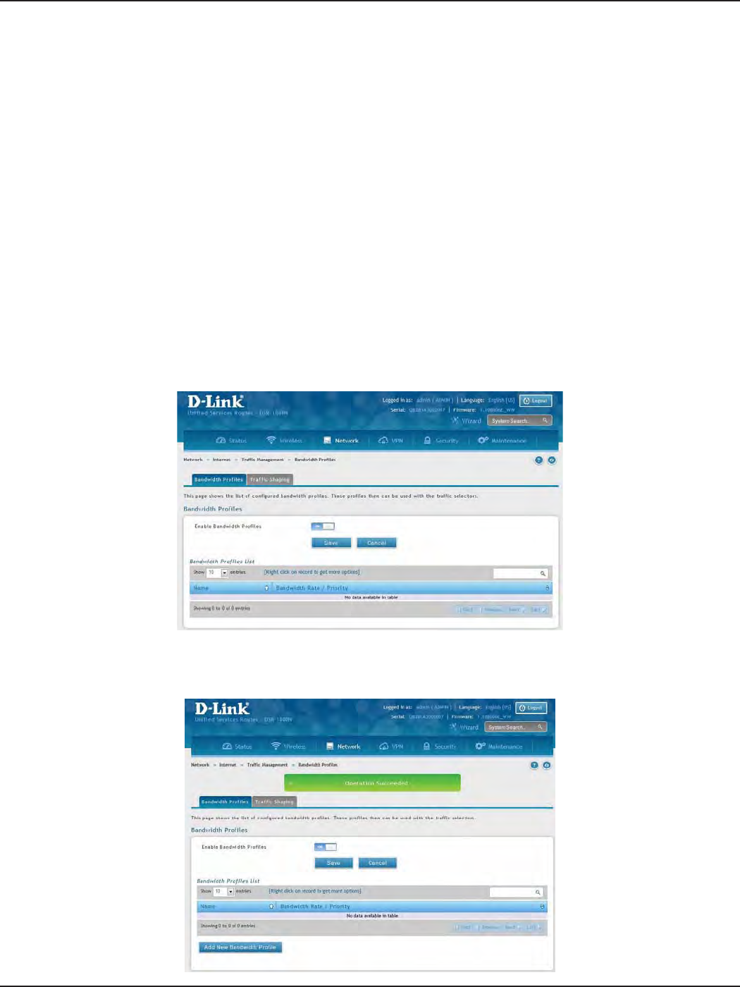
D-Link DSR-Series User Manual 54
Section 5 - Connect to the Internet
Trac Management
Path: Network > Internet > Trac Management > Bandwidth Proles
Bandwidth proles allow you to regulate the trac ow from the LAN to WAN 1 or WAN 2. This is useful to ensure
that low priority LAN users (like guests or HTTP service) do not monopolize the available WAN’s bandwidth for
cost-savings or bandwidth-priority-allocation purposes.
Bandwidth proles conguration consists of enabling the bandwidth control feature from the GUI and adding
a prole which denes the control parameters. The prole can then be associated with a trac selector, so that
bandwidth prole can be applied to the trac matching the selectors. Selectors are elements like IP addresses
or services that would trigger the congured bandwidth regulation.
To edit, delete, or create a new bandwidth prole:
1. Click Network > Internet > Trac Management > Bandwidth Proles.
2. Toggle Enable Bandwidth Proles to ON and click Save.
Bandwidth Proles
3. Click Add New Bandwidth Prole.
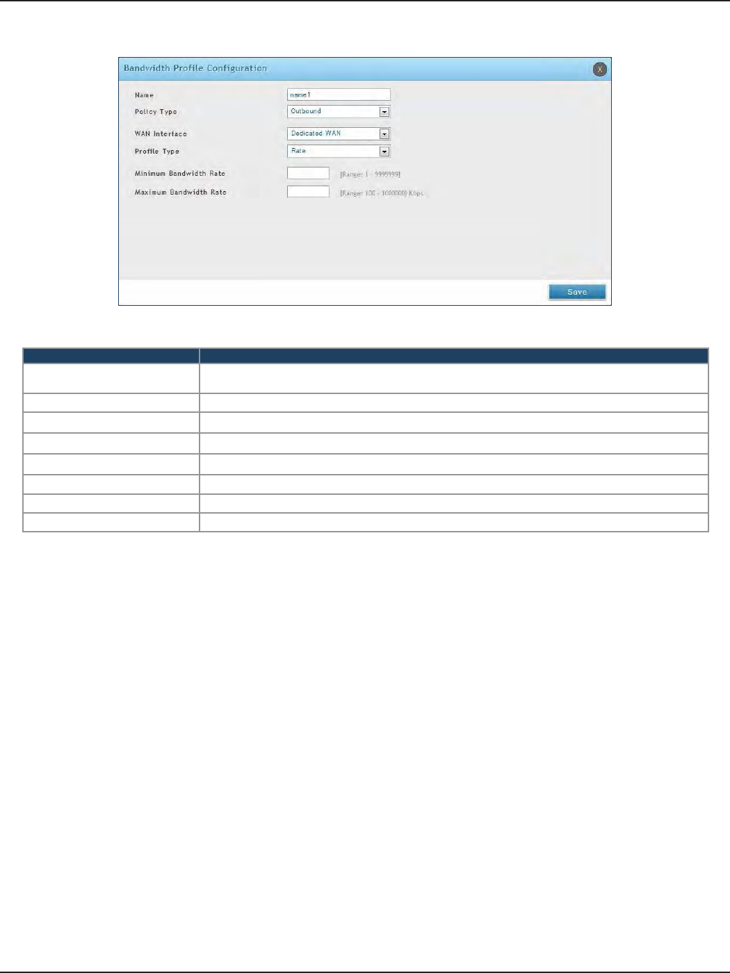
D-Link DSR-Series User Manual 55
Section 5 - Connect to the Internet
4. Enter the following information and click Save.
Field Description
Name Enter a name for your prole. This identier is used to associate the congured prole to the
trac selector.
Policy Type Select the policy type (Inbound or Outbound) from the drop-down menu.
WAN Interface Select which WAN interface you want to associate this prole with.
Prole Type Select either Priority or Rate from the drop-down menu.
Priority If you selected Priority, select Low, Medium, or High.
Minimum Bandwidth Rate If you selected Rate, enter the minimum bandwidth rate.
Maximum Bandwidth Rate If you selected Rate, enter the maximum bandwidth rate.
Save Click Save to save your reservation.
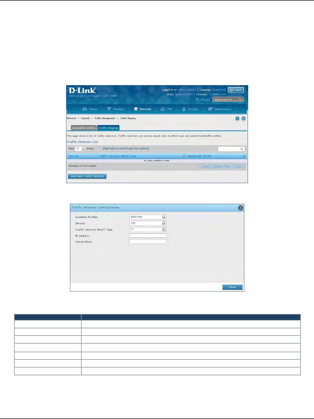
D-Link DSR-Series User Manual 56
Section 5 - Connect to the Internet
Path: Network > Internet > Trac Management > Trac Shaping
Once a prole has been created it can then be associated with a trac ow from the LAN to WAN. Trac selector
conguration binds a bandwidth prole to a type or source of LAN trac with the following settings.
To create a trac selector:
1. Click Network > Internet > Trac Management > Trac Shaping.
Trac Shaping
2. Click Add New Trac Selector.
Field Description
Available Proles Select a bandwidth prole from the drop-down menu.
Service Select a service from the drop-down menu.
Trac Selector Match Type Select IP or MAC Address.
IP Address If you selected IP, enter the IP address of the source associated with this prole.
Subnet Mask If you selected IP, enter a subnet mask.
MAC Address If you selected MAC, enter the MAC address of the source associated with this prole.
Save Click to save and activate your settings.
3. Complete the elds from the table below and click Save.
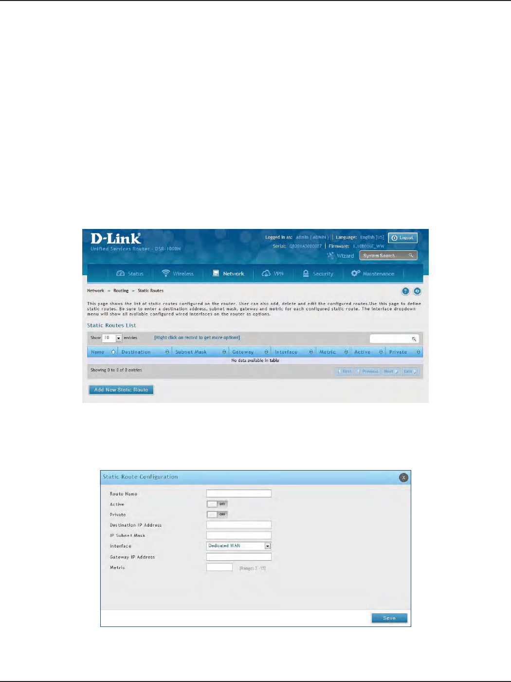
D-Link DSR-Series User Manual 57
Section 5 - Connect to the Internet
Path: Network > Routing > Static Routes
Manually adding static routes to this device allows you to dene the path selection of trac from one interface
to another. There is no communication between this router and other devices to account for changes in the path;
once congured the static route will be active and eective until the network changes.
The List of Static Routes displays all routes that have been added manually by an administrator and allows several
operations on the static routes.
To create a new static route:
1. Click Network > Routing > Static Routes.
Static Routes
2. Click Add New Static Route.
3. Complete the elds in the table on the next page and click Save.
Routing

D-Link DSR-Series User Manual 58
Section 5 - Connect to the Internet
Field Description
Route Name Enter a name for your route.
Active Toggle to ON to activate this route or to OFF to deactivate.
Private Toggle to ON to make this route private. If the route is made private, then the route will not be shared
in a RIP broadcast or multicast.
Destination IP Address Enter the IP address of the static route’s destination.
IP Subnet Mask Enter the subnet mask of the static route.
Interface The physical network interface (WAN1, WAN2, WAN3, DMZ or LAN), through which this route is
accessible.
Gateway IP Address IP address of the gateway through which the destination host or network can be reached.
Metric Determines the priority of the route. If multiple routes to the same destination exist, the route with
the lowest metric is chosen.
Save Click Save to save your route.
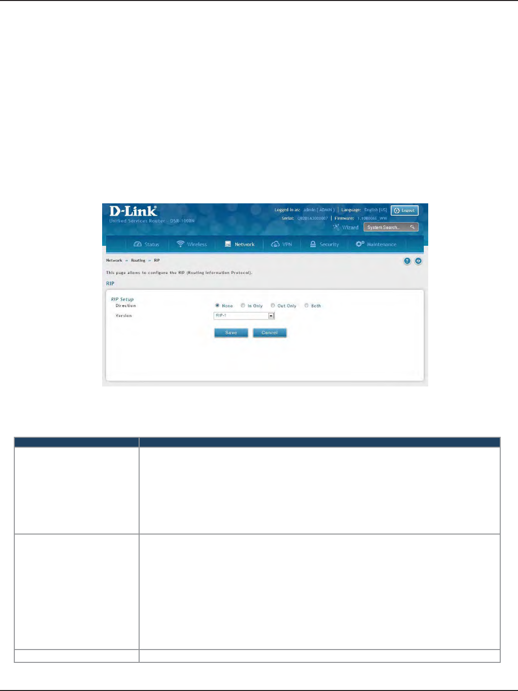
D-Link DSR-Series User Manual 59
Section 5 - Connect to the Internet
RIP
Dynamic routing using the Routing Information Protocol (RIP) is an Interior Gateway Protocol (IGP) that is
common in LANs. With RIP this router can exchange routing information with other supported routers in the
LAN and allow for dynamic adjustment of routing tables in order to adapt to modications in the LAN without
interrupting trac ow.
Note: The DSR-150/150N/250/250N routers do not support RIP.
Path: Network > Routing > RIP
To congure RIP:
1. Click Network > Routing > RIP.
2. Complete the elds in the table below and click Save.
Field Description
Direction
The RIP direction will dene how this router sends and receives RIP packets. Select one of the following:
• Both: The router both broadcasts its routing table and also processes RIP information received
from other routers. This is the recommended setting in order to fully utilize RIP capabilities.
• Out Only: The router broadcasts its routing table periodically but does not accept RIP information
from other routers.
• In Only: The router accepts RIP information from other routers, but does not broadcast its routing
table.
• None: The router neither broadcasts its route table nor does it accept any RIP packets from other
routers. This eectively disables RIP.
Version
The RIP version is dependent on the RIP support of other routing devices in the LAN.
• Disabled: This is the setting when RIP is disabled.
• RIP-1: A class-based routing version that does not include subnet information. This is the most
commonly supported version.
• RIP-2: Includes all the functionality of RIPv1 plus it supports subnet information. Though the data
is sent in RIP-2 format for both RIP-2B and RIP-2M, the mode in which packets are sent is dierent.
RIP-2B broadcasts data in the entire subnet while RIP-2M sends data to multicast addresses.
Note: If RIP-2B or RIP-2M is the selected version, authentication between this router and other
routers (congured with the same RIP version) is required. MD5 authentication is used in a rst/
second key exchange process. The authentication key validity lifetimes are congurable to ensure
that the routing information exchange is with current and supported routers detected on the LAN.
Save Click Save to save your settings.
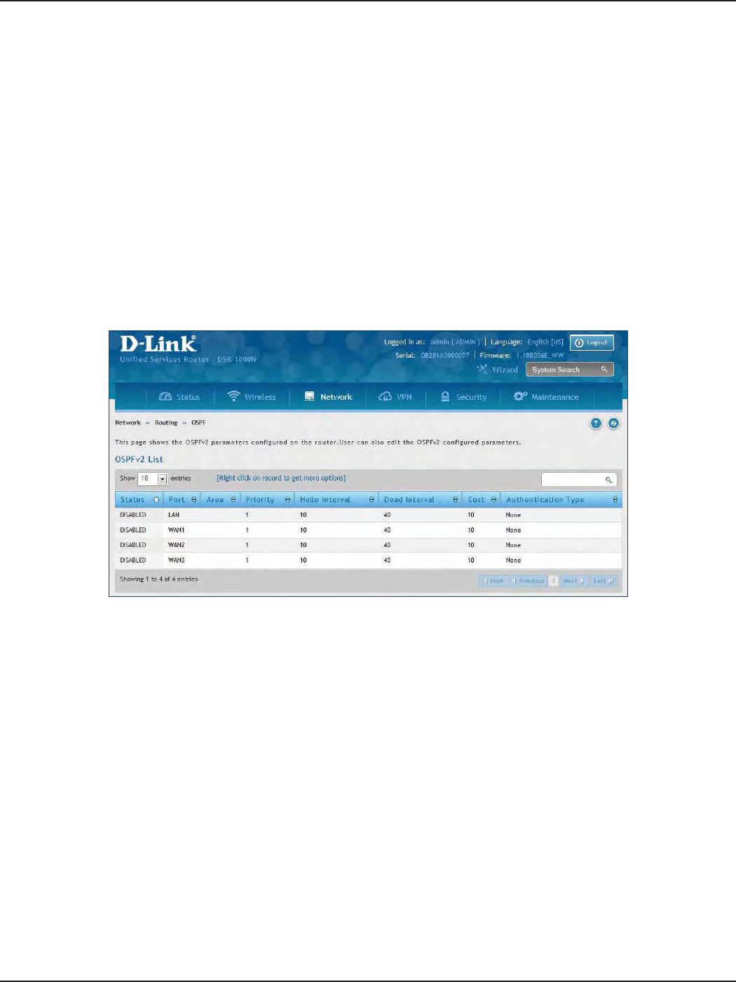
D-Link DSR-Series User Manual 60
Section 5 - Connect to the Internet
OSPF
Path: Network > Routing > OSPF
OSPF is an interior gateway protocol that routes Internet Protocol (IP) packets solely within a single routing
domain. It gathers link state information from available routers and constructs a topology map of the network.
OSPF version 2 is a routing protocol which described in RFC2328 - OSPF Version 2. OSPF is IGP (Interior Gateway
Protocols). OSPF is widely used in large networks such as ISP backbone and enterprise networks.
Note: The DSR-150/150N/250/250N routers do not support OSPFv2.
To congure OSPF:
1. Click Network > Routing > OSPF.
2. Right-click the port you want to edit (LAN/WAN1/WAN2/WAN3) and select Edit.
3. Complete the elds in the table on the next page and click Save.
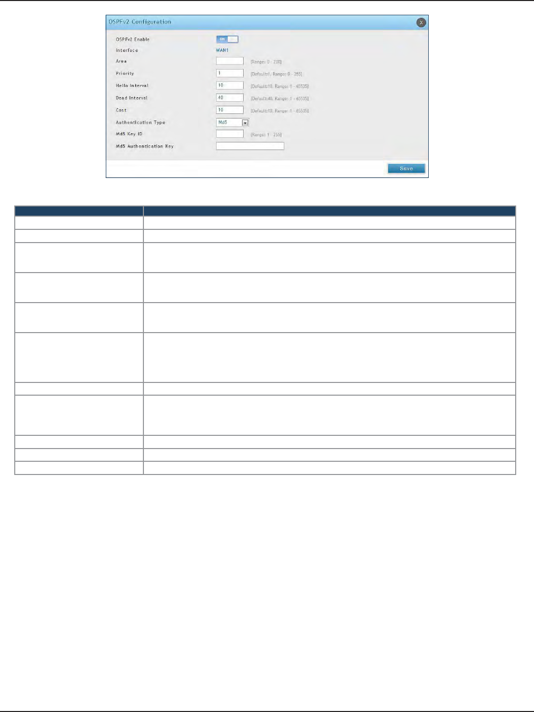
D-Link DSR-Series User Manual 61
Section 5 - Connect to the Internet
Field Description
OSPFv2 Enable Toggle ON to enable OSPF.
Interface Displays the physical network interface on which OSPFv2 is Enabled/Disabled.
Area
Enter the area to which the interface belongs. Two routers having a common segment; their interfaces
have to belong to the same area on that segment. The interfaces should belong to the same subnet and
have similar mask.
Priority
Helps to determine the OSPFv2 designated router for a network. The router with the highest priority
will be more eligible to become Designated Router. Setting the value to 0 makes the router ineligible to
become Designated Router. The default value is 1. Lower the value means higher the priority.
Hello Interval
The number of seconds for Hello Interval timer value. Enter the number in seconds that the Hello packet
will be sent. This value must be the same for all routers attached to a common network. The default
value is 10 seconds.
Dead Interval
The number of seconds that a device’s hello packets must not have been seen before its neighbors
declare the OSPF router down. This value must be the same for all routers attached to a common
network. The default value is 40 seconds. OSPF requires these intervals to be exactly the same between
two neighbors. If any of these intervals are dierent, these routers will not become neighbors on a
particular segment.
Cost Enter the cost of sending a packet on an OSPFv2 interface.
Authentication Type
Select one of the following authentication types:
• None: The interface does not authenticate OSPF packets.
• Simple: OSPF packets are authenticated using simple text key.
• MD5: The interface authenticates OSPF packets with MD5 authentication.
Md5 Key ID If MD5 authentication is selected, enter the MD5 key ID.
Md5 Authentication Key If MD5 authentication is selected, enter the MD5 authentication key.
Save Click Save to save your settings.
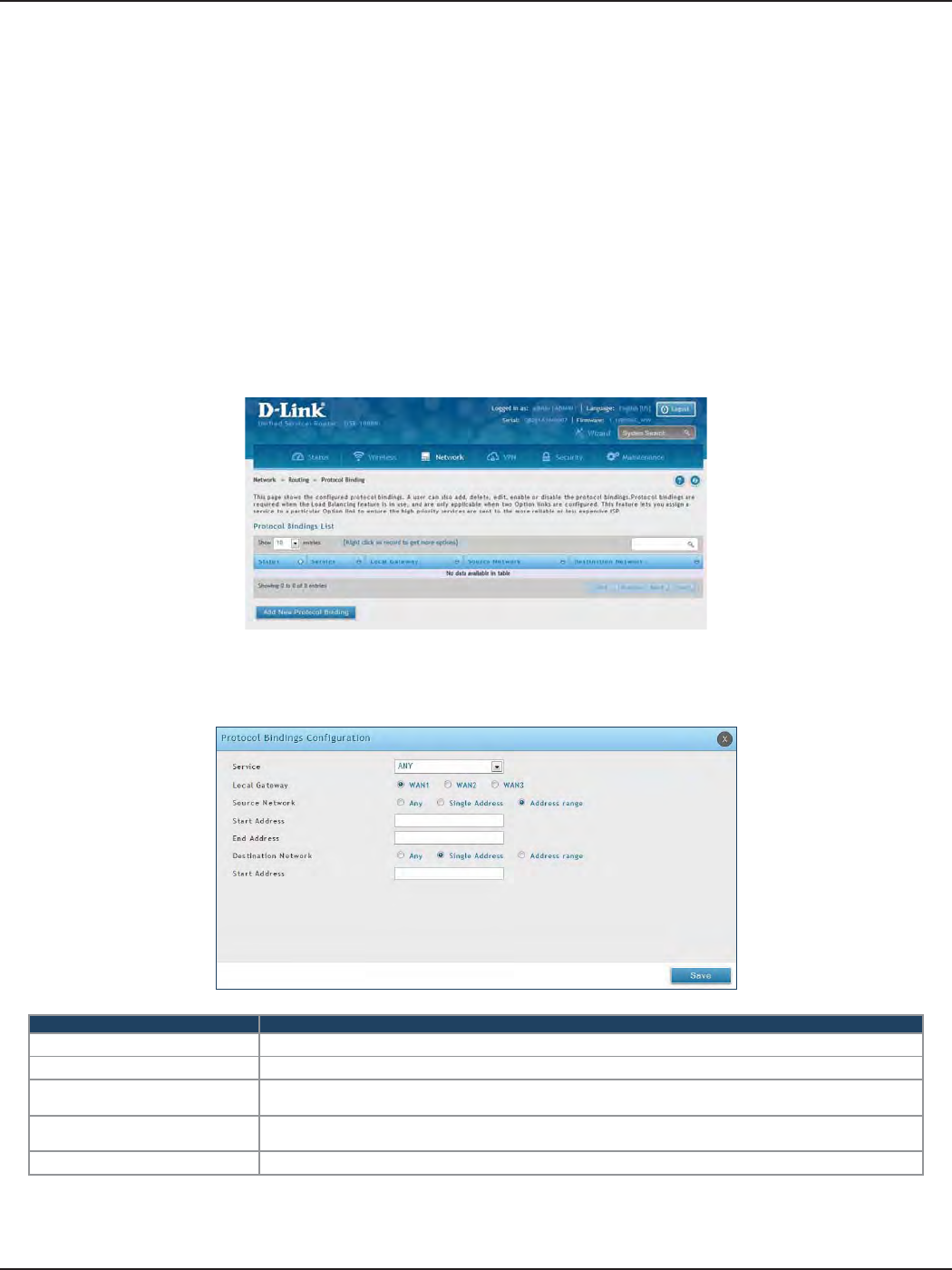
D-Link DSR-Series User Manual 62
Section 5 - Connect to the Internet
Protocol Binding
Path: Network > Routing > Protocol Binding
Protocol bindings are useful when the Load Balancing feature is in use. Selecting from a list of congured services
or any of the user-dened services, the type of trac can be assigned to go over only one of the available WAN
ports. For increased exibility the source network or machines can be specied as well as the destination network
or machines. For example, the VOIP trac for a set of LAN IP addresses can be assigned to one WAN and any
VOIP trac from the remaining IP addresses can be assigned to the other WAN link. Protocol bindings are only
applicable when load balancing mode is enabled and more than one WAN is congured.
To add, edit, or delete a protocol binding entry:
1. Click Network > Routing > Protocol Binding.
2. Right-click a current entry and select Edit or Delete. To add a new entry, click Add New Protocol Binding.
3. Complete the elds in the table below and click Save.
Field Description
Service Select a service from the drop-down menu.
Local Gateway Select a WAN interface.
Source Network Select the source network: Any, Single Address, or Address Range. If Single Address or Address
Range is selected, enter the IP address or IP range.
Destination Network Select the destination network: Any, Single Address, or Address Range. If Single Address or Address
Range is selected, enter the IP address or IP range.
Save Click Save to save your settings.
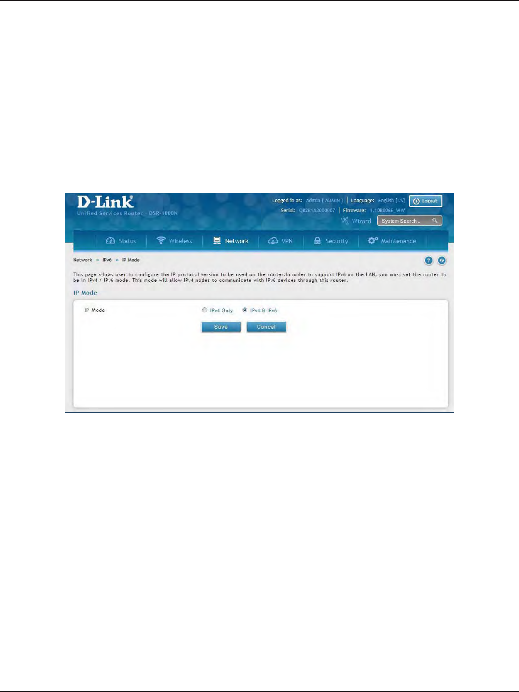
D-Link DSR-Series User Manual 63
Section 5 - Connect to the Internet
IPv6
IP Mode
Path: Network > IPv6 > IP Mode
This page allows you to congure the IP protocol version to be used on the router. In order to support IPv6 on
your local network (LAN), you must set the router to be in IPv4 / IPv6 mode. This mode will allow IPv4 nodes to
communicate with IPv6 devices through this router.
To enable IPv6 on the router:
1. Click Network > IPv6 > IP Mode.
2. Select IPv4 & IPv6.
3. Click Save.
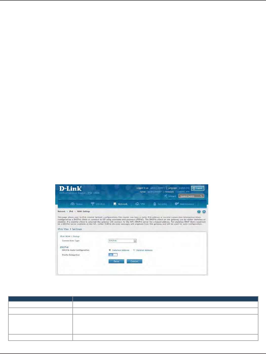
D-Link DSR-Series User Manual 64
Section 5 - Connect to the Internet
WAN Settings
Path: Network > IPv6 > WAN1 Settings
For IPv6 WAN connections, this router can have a static IPv6 address or receive connection information when
congured as a DHCPv6 client. In the case where the ISP assigns you a xed address to access the internet, the
static conguration settings must be completed. In addition to the IPv6 address assigned to your router, the
IPv6 prex length dened by the ISP is needed. The default IPv6 Gateway address is the server at the ISP that
this router will connect to for accessing the internet. The primary and secondary DNS servers on the ISP’s IPv6
network are used for resolving internet addresses, and these are provided along with the static IP address and
prex length from the ISP.
When the ISP allows you to obtain the WAN IP settings via DHCP, you need to provide details for the DHCPv6
client conguration. The DHCPv6 client on the gateway can be either stateless or stateful. If a stateful client is
selected the gateway will connect to the ISP’s DHCPv6 server for a leased address. For stateless DHCP there need
not be a DHCPv6 server available at the ISP, rather ICMPv6 discover messages will originate from this gateway
and will be used for auto conguration.
A third option to specify the IP address and prex length of a preferred DHCPv6 server is available as well.
To congure a dynamic (DHCP) IPv6 Internet connection:
1. Click Network > IPv6 > WAN1 Settings.
2. Complete the elds in the table below and click Save.
Field Description
Connection Type Select DHCPv6 from the drop-down menu.
DHCPv6 Auto Conguration Select either Stateless Address or Stateful Address.
Prex Delegation
Select this option to request router advertisement prex from any available
DHCPv6 servers available on the ISP, the obtained prex is updated to the advertised prexes on
the LAN side. This option can be selected only in Stateless Address Auto Conguration mode of
DHCPv6 Client.
Save Click Save to save your settings.
Dynamic IP
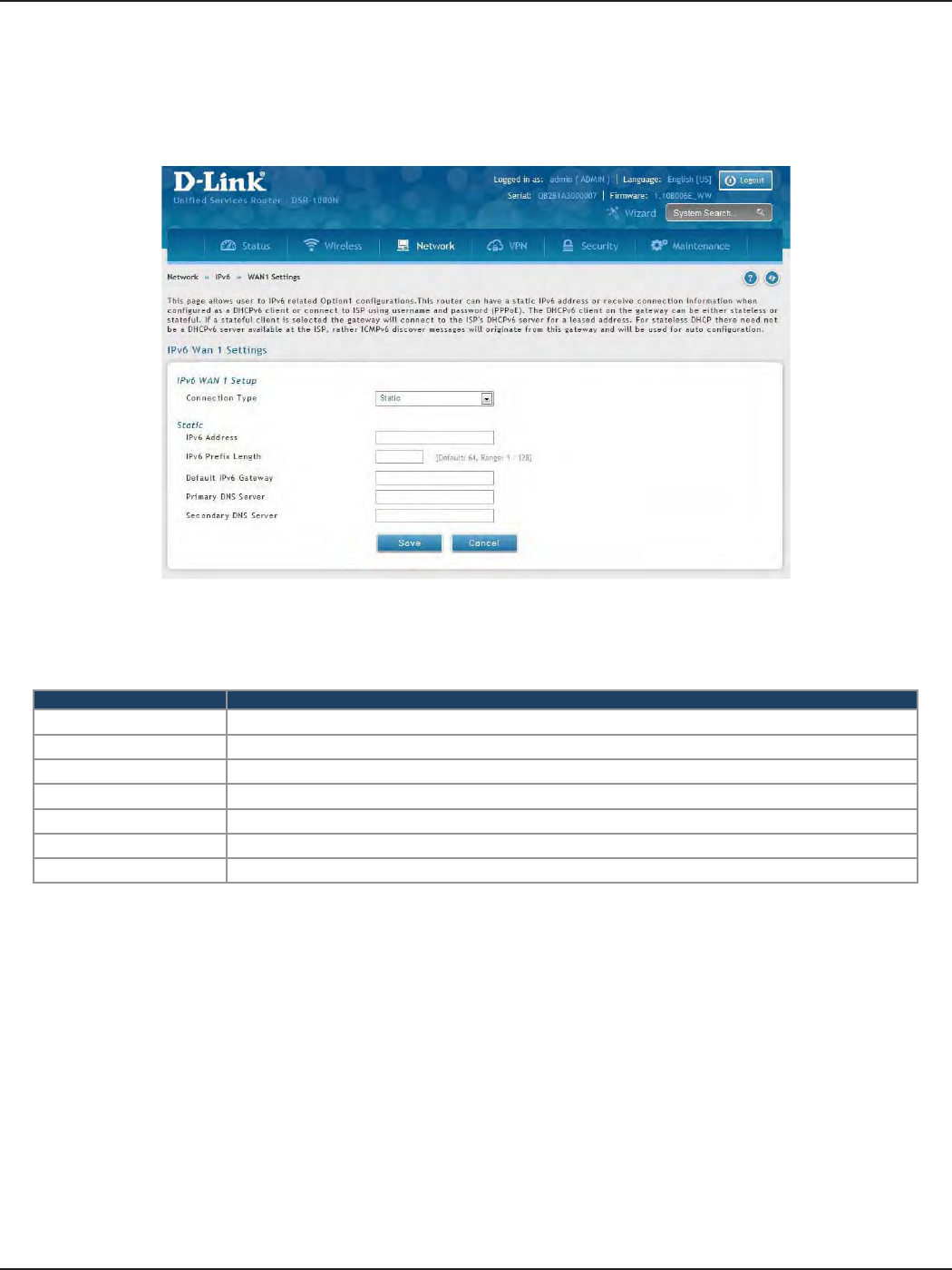
D-Link DSR-Series User Manual 65
Section 5 - Connect to the Internet
To congure a static IPv6 Internet connection:
1. Click Network > IPv6 > WAN1 Settings.
2. Complete the elds in the table below and click Save.
Static IP
Field Description
Connection Type Select Static.
IPv6 Address Enter the IP address supplied by your ISP.
IPv6 Prex Length Enter the IPv6 prex length supplied by your ISP.
Default IPv6 Gateway Enter the IPv6 gateway address supplied by your ISP.
Primary DNS Server Enter the primary DNS server IP address.
Secondary DNS Server Enter the secondary DNS server IP address.
Save Click Save to save and activate your settings.
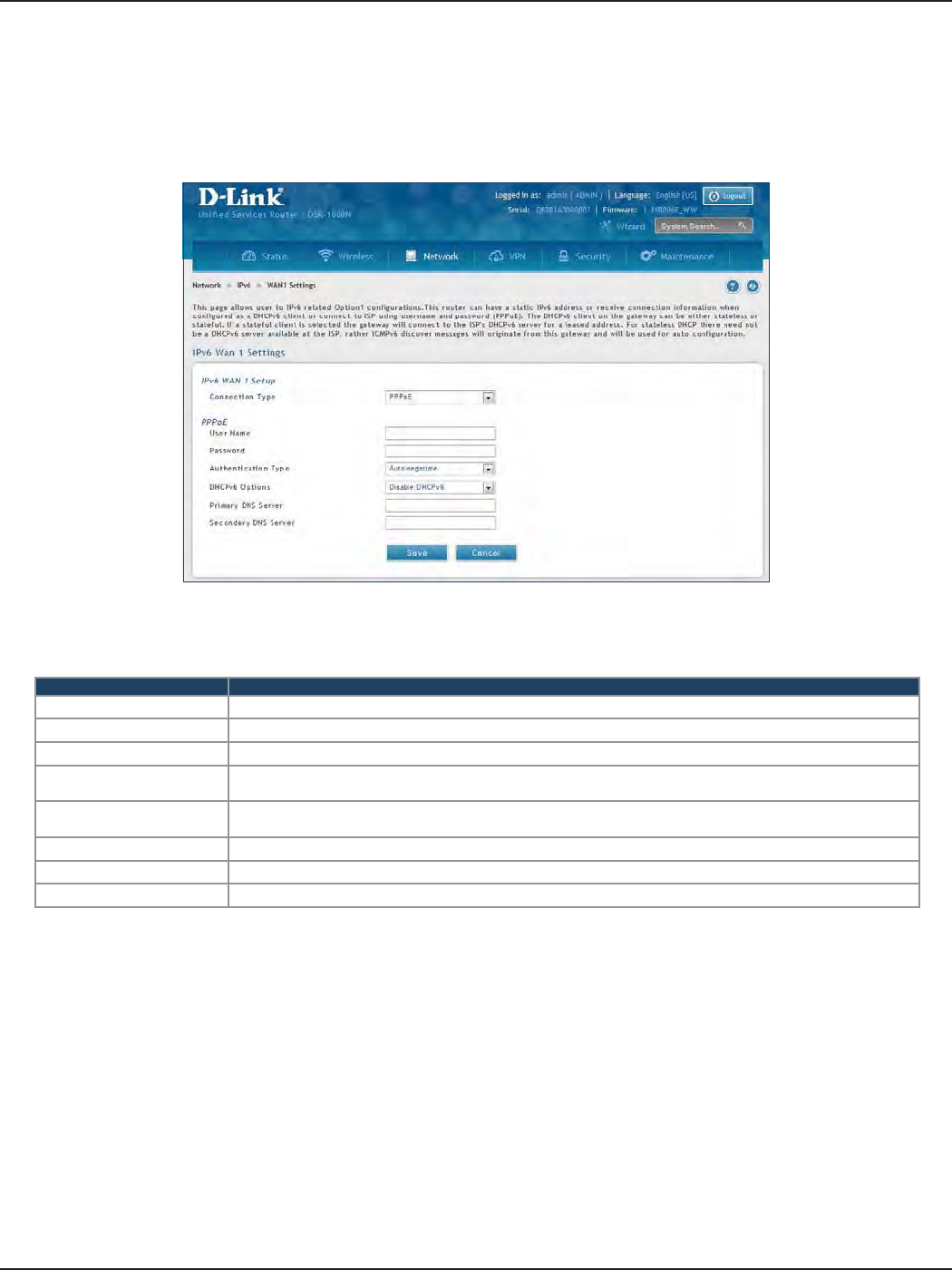
D-Link DSR-Series User Manual 66
Section 5 - Connect to the Internet
To congure a dynamic (DHCP) IPv6 Internet connection:
1. Click Network > IPv6 > WAN1 Settings.
PPPoE
2. Complete the elds in the table below and click Save.
Field Description
Connection Type Select PPPoE.
User Name Enter your PPPoE user name.
Password Enter your PPPoE password.
Authentication Type Select the authentication type from the drop-down menu (Auto-negotiate/PAP/CHAP/MS-CHAP/MS-
CHAPv2).
DHCPv6 Options Select the mode of DHCPv6 client that will start in this mode (Disable dhcpv6/Stateless dhcpv6/Stateful
dhcpv6/Stateless dhcpv6 with prex delegation.
Primary DNS Server Enter the primary DNS server IP address.
Secondary DNS Server Enter the secondary DNS server IP address.
Save Click Save to save and activate your settings.
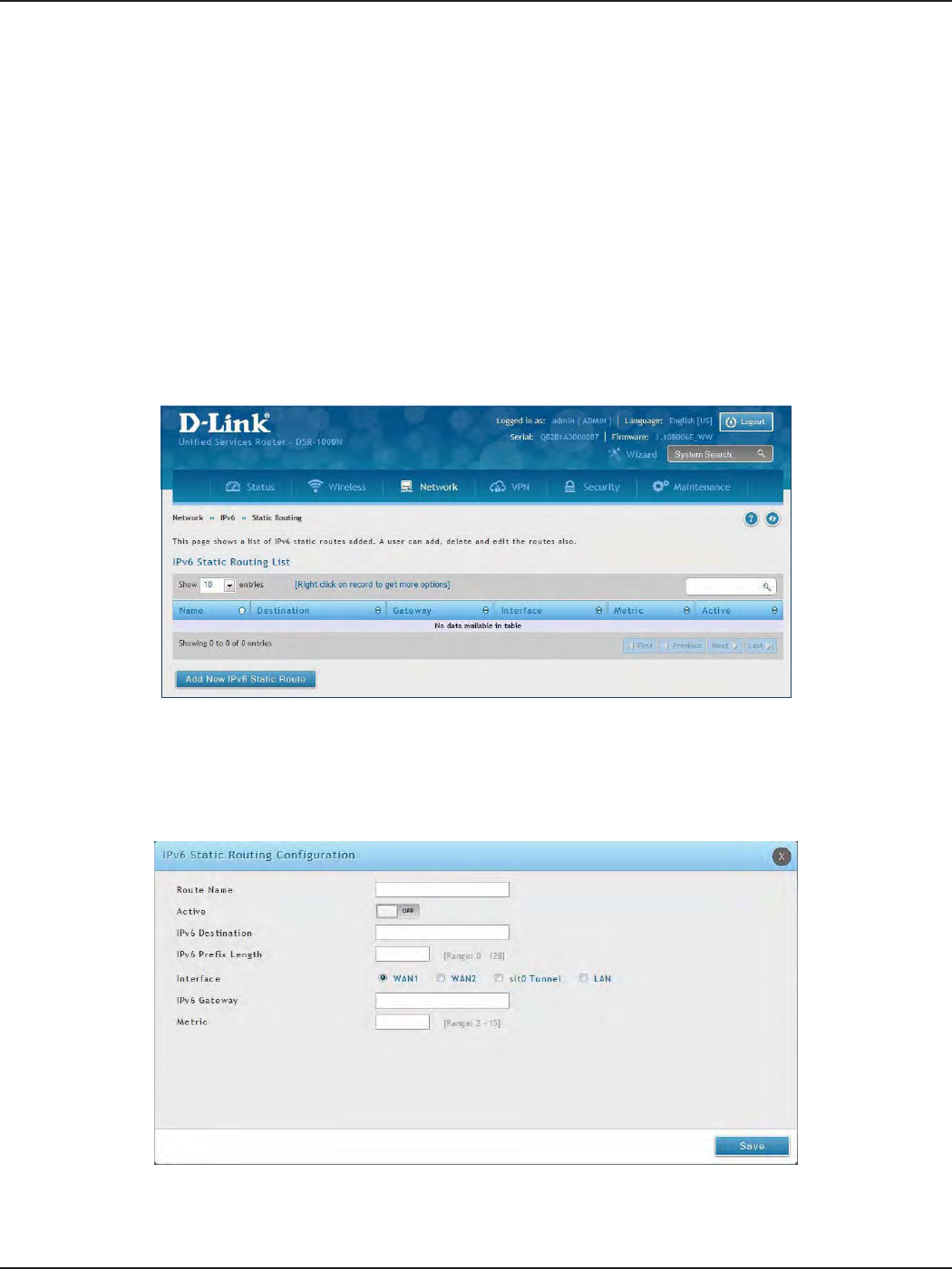
D-Link DSR-Series User Manual 67
Section 5 - Connect to the Internet
Path: Network > IPv6 > Static Routing
Manually adding static routes to this device allows you to dene the path selection of trac from one interface
to another. There is no communication between this router and other devices to account for changes in the path;
once congured the static route will be active and eective until the network changes.
The List of Static Routes displays all routes that have been added manually by an administrator and allows several
operations on the static routes.
To create a new static route:
1. Click Network > IPv6 > Static Routing.
Static Routing
2. Click Add New IPv6 Static Route.
3. Complete the elds in the table on the next page and click Save.

D-Link DSR-Series User Manual 68
Section 5 - Connect to the Internet
Field Description
Route Name Enter a name for your route.
Active Toggle to ON to activate this route or to OFF to deactivate.
IPv6 Destination Enter the IP address of the static route’s destination.
IPv6 Prex Length Enter the prex length of the static route.
Interface The physical network interface (WAN1, WAN2, WAN3, DMZ or LAN), through which this route is
accessible.
IPv6 Gateway IPv6 address of the gateway through which the destination host or network can be reached.
Metric Determines the priority of the route. If multiple routes to the same destination exist, the route with
the lowest metric is chosen.
Save Click Save to save your route.
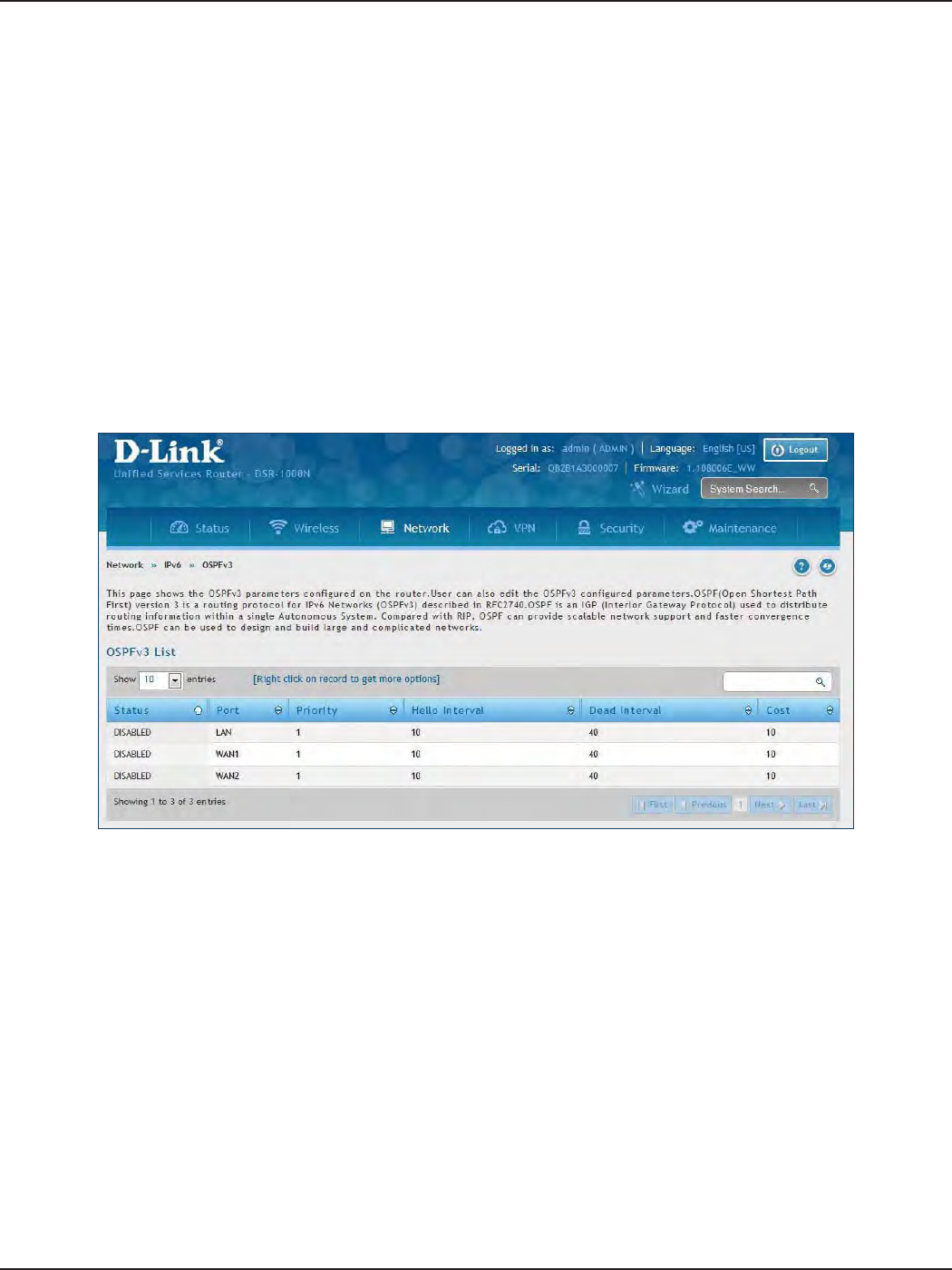
D-Link DSR-Series User Manual 69
Section 5 - Connect to the Internet
Path: Network > IPv6 > OSPFv3
OSPF is an interior gateway protocol that routes Internet Protocol (IP) packets solely within a single routing
domain. It gathers link state information from available routers and constructs a topology map of the network.
Open Shortest Path First version 3 (OSPFv3) supports IPv6. To enable an OSPFv3 process on a router, you need to
enable the OSPFv3 process globally, assign the OSPFv3 process a router ID, and enable the OSPFv3 process on
related interfaces.
Note: The DSR-150/150N/250/250N routers do not support OSPFv3.
To congure OSPF:
1. Click Network > IPv6 > OSPFv3.
2. Right-click the port you want to edit (LAN/WAN1/WAN2) and select Edit.
3. Complete the elds in the table on the next page and click Save.
OSPFv3
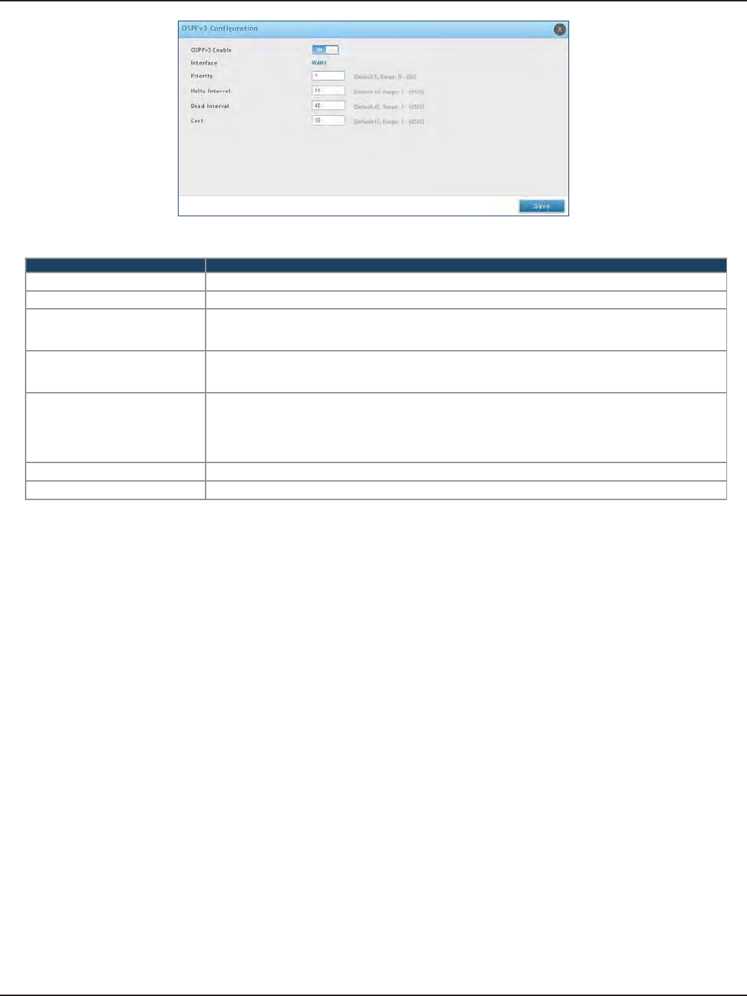
D-Link DSR-Series User Manual 70
Section 5 - Connect to the Internet
Field Description
OSPFv3 Enable Toggle ON to enable OSPFv3.
Interface Displays the physical network interface on which OSPFv3 is Enabled/Disabled.
Priority
Helps to determine the OSPFv3 designated router for a network. The router with the highest priority
will be more eligible to become Designated Router. Setting the value to 0 makes the router ineligible to
become Designated Router. The default value is 1. Lower the value means higher the priority.
Hello Interval
The number of seconds for Hello Interval timer value. Enter the number in seconds that the Hello packet
will be sent. This value must be the same for all routers attached to a common network. The default
value is 10 seconds.
Dead Interval
The number of seconds that a device’s hello packets must not have been seen before its neighbors
declare the OSPF router down. This value must be the same for all routers attached to a common
network. The default value is 40 seconds. OSPF requires these intervals to be exactly the same between
two neighbors. If any of these intervals are dierent, these routers will not become neighbors on a
particular segment.
Cost Enter the cost of sending a packet on an OSPFv3 interface.
Save Click Save to save your settings.
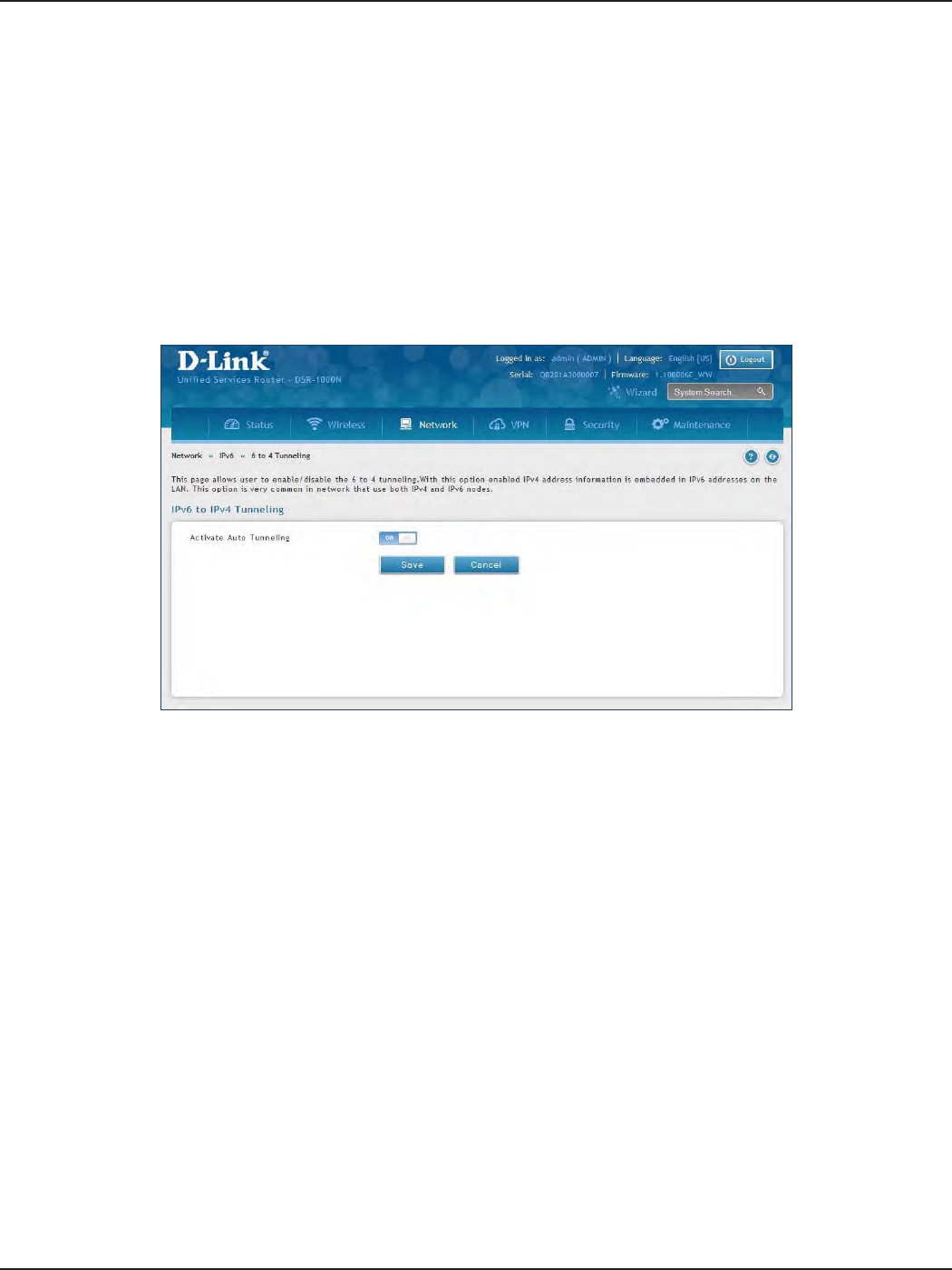
D-Link DSR-Series User Manual 71
Section 5 - Connect to the Internet
Path: Network > IPv6 > 6 to 4 Tunneling
6to4 is an Internet transition mechanism for migrating from IPv4 to IPv6, a system that allows IPv6 packets to be
transmitted over an IPv4 network. Select the check box to Enable Automatic Tunneling and allow trac from an
IPv6 LAN to be sent over an IPv4 Option to reach a remote IPv6 network.
To enable 6 to 4 tunneling:
1. Click Network > IPv6 > 6 to 4 Tunneling.
2. Toggle Activate Auto Tunneling to ON.
3. Click Save.
6 to 4 Tunneling
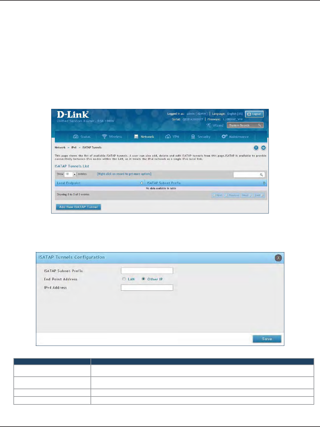
D-Link DSR-Series User Manual 72
Section 5 - Connect to the Internet
Path: Network > IPv6 > 6 to 4 Tunneling
ISATAP (Intra-Site Automatic Tunnel Addressing Protocol) is an IPv6 transition mechanism meant to transmit
IPv6 packets between dual-stack nodes on top of an IPv4 network. ISATAP species an IPv6-IPv4 compatibility
address format as well as a means for site border router discovery. ISATAP also species the operation of IPv6 over
a specic link layer - that being IPv4 used as a link layer for IPv6.
ISATAP
To add, edit, or delete a ISATAP entry:
1. Click Network > IPv6 > ISATAP.
2. Right-click a current entry and select Edit or Delete. To add a new entry, click Add New ISATAP Tunnel.
3. Complete the elds in the table below and click Save.
Field Description
ISATAP Subnet Prex This is the 64-bit subnet prex that is assigned to the logical ISATAP subnet for this intranet. This can be
obtained from your ISP or internet registry, or derived from RFC 4193.
End Point Address This is the endpoint address for the tunnel that starts with this router. The endpoint can be the LAN
interface (assuming the LAN is an IPv4 network), or a specic LAN IPv4 address.
IPv4 Address The end point address if not the entire LAN.
Save Click Save to save your settings.
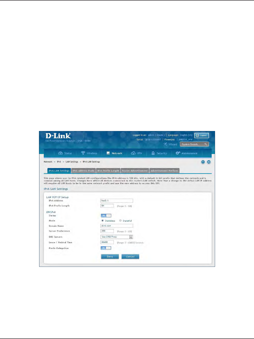
D-Link DSR-Series User Manual 73
Section 5 - Connect to the Internet
LAN Settings
Path: Network > IPv6 > LAN Settings > IPv6 LAN Settings
In IPv6 mode, the LAN DHCP server is disabled by default (similar to IPv4 mode). The DHCPv6 server will serve
IPv6 addresses from congured address pools with the IPv6 Prex Length assigned to the LAN.
The default IPv6 LAN address for the router is fec0::1. You can change this 128-bit IPv6 address based on your
network requirements. The other eld that denes the LAN settings for the router is the prex length. The IPv6
network (subnet) is identied by the initial bits of the address called the prex. By default this is 64 bits long. All
hosts in the network have common initial bits for their IPv6 address; the number of common initial bits in the
network’s addresses is set by the prex length eld.
To congure IPv6 LAN settings on the router:
1. Click Network > IPv6 > LAN Settings > IPv6 LAN Settings.
2. Complete the elds in the table on the next page and click Save.
DHCPv6 Server

D-Link DSR-Series User Manual 74
Section 5 - Connect to the Internet
Field Description
IPv6 Address Enter the IPv6 LAN address for the router.
IPv6 Prex Length Enter the prex length.
Status Toggle to ON to enable DHCPv6.
Mode
The IPv6 DHCP server is either stateless or stateful. If stateless is selected an external IPv6 DHCP server is
not required as the IPv6 LAN hosts are auto-congured by this router. In this case the router advertisement
daemon (RADVD) must be congured on this device and ICMPv6 router discovery messages are used by the
host for auto-conguration. There are no managed addresses to serve the LAN nodes. If stateful is selected
the IPv6 LAN host will rely on an external DHCPv6 server to provide required conguration settings.
Domain Name Enter a domain name (optional).
Server Preference
Server Preference is used to indicate the preference level of this DHCP server. DHCP advertise messages with
the highest server preference value to a LAN host are preferred over other DHCP server advertise messages.
The default is 255.
DNS Servers
The DNS server details can be manually entered here (primary/secondary options. An alternative is to
allow the LAN DHCP client to receive the DNS server details from the ISP directly. By selecting Use DNS
proxy, this router acts as a proxy for all DNS requests and communicates with the ISP’s DNS servers (a WAN
conguration parameter).
Lease / Rebind Time Enter the duration of the DHCPv6 lease from this router to the LAN client.
Prex Delegation Toggle to ON to enable prex delegation in DHCPv6 server. This option can be selected only in Stateless
Address Auto Conguration mode of DHCPv6 server.
Save Click Save at the bottom to save and activate your settings.
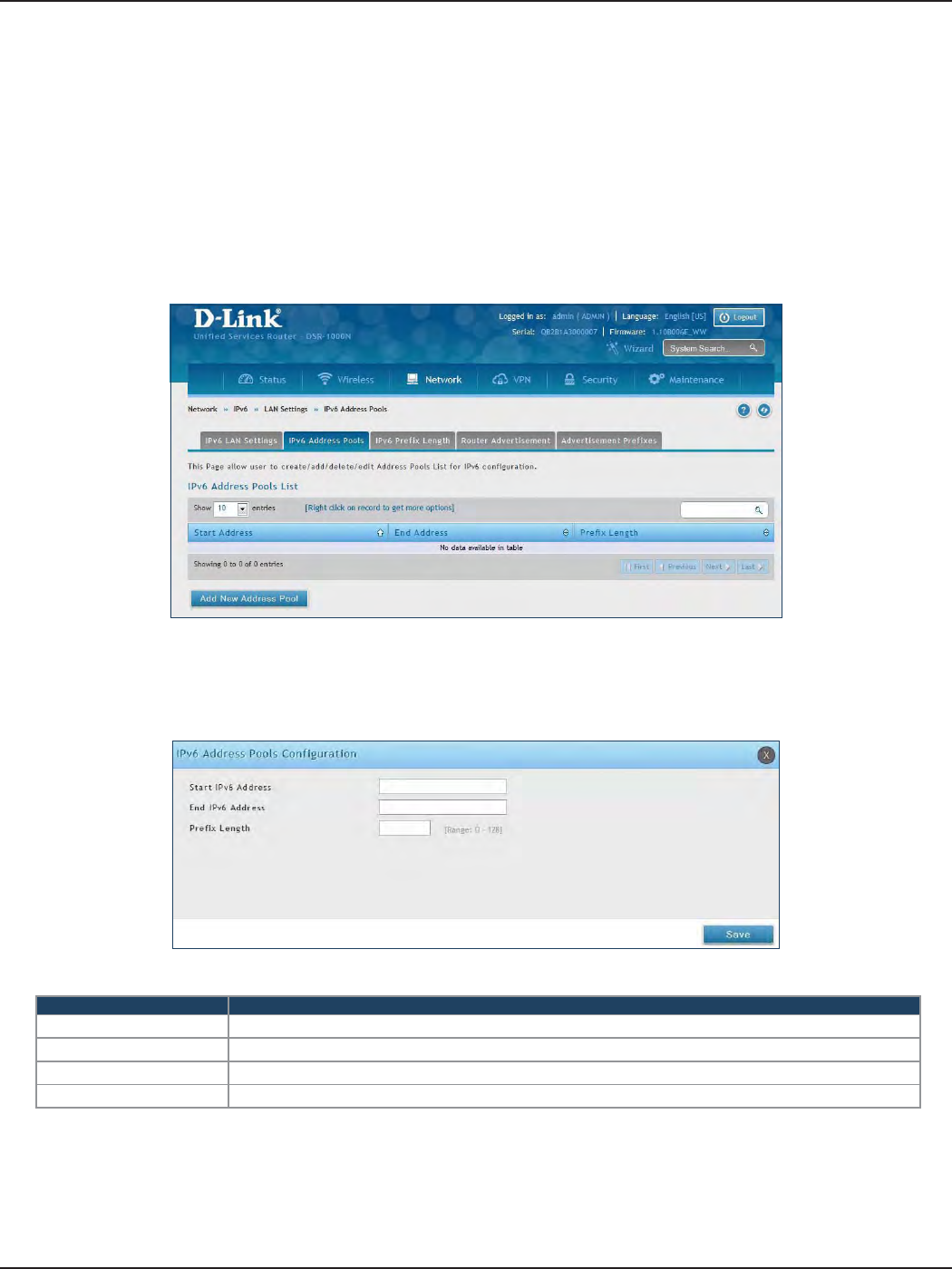
D-Link DSR-Series User Manual 75
Section 5 - Connect to the Internet
IPv6 Address Pools
Path: Network > IPv6 > LAN Settings > IPv6 Address Pools
This feature allows you to dene the IPv6 delegation prex for a range of IP addresses to be served by the
router’s DHCPv6 server. Using a delegation prex you can automate the process of informing other networking
equipment on the LAN of DHCP information specic for the assigned prex.
To add, edit, or delete a IPv6 address pool entry:
1. Click Network > IPv6 > LAN Settings > IPv6 Address Pools tab.
2. Right-click a current entry and select Edit or Delete. To add a new entry, click Add New Address Pool.
3. Complete the elds in the table below and click Save.
Field Description
Start IPv6 Address Enter the starting IPv6 LAN address.
End IPv6 Address Enter the ending IPv6 LAN address.
Prex Length Enter the prex length.
Save Click Save at the bottom to save and activate your settings.
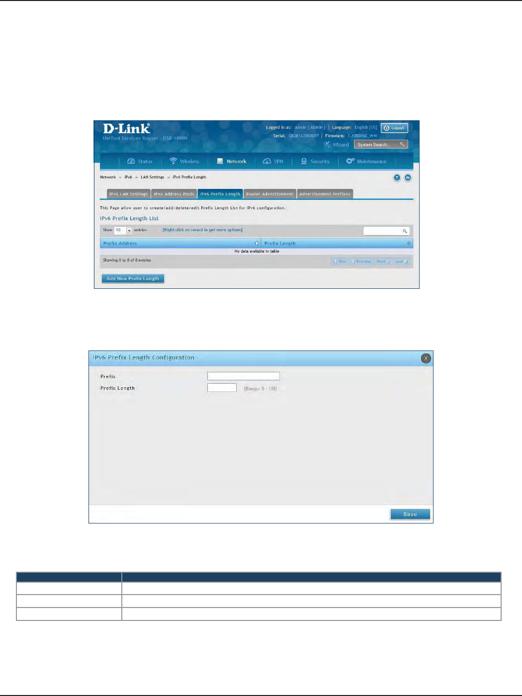
D-Link DSR-Series User Manual 76
Section 5 - Connect to the Internet
IPv6 Prex Length
Path: Network > IPv6 > LAN Settings > IPv6 Prex Length
To add, edit, or delete a IPv6 prex length entry:
1. Click Network > IPv6 > LAN Settings > IPv6 Prex Length tab.
2. Right-click a current entry and select Edit or Delete. To add a new entry, click Add New Prex Length.
3. Complete the elds in the table below and click Save.
Field Description
Prole Enter a name for this prole.
Prex Length Enter the prex length.
Save Click Save at the bottom to save and activate your settings.
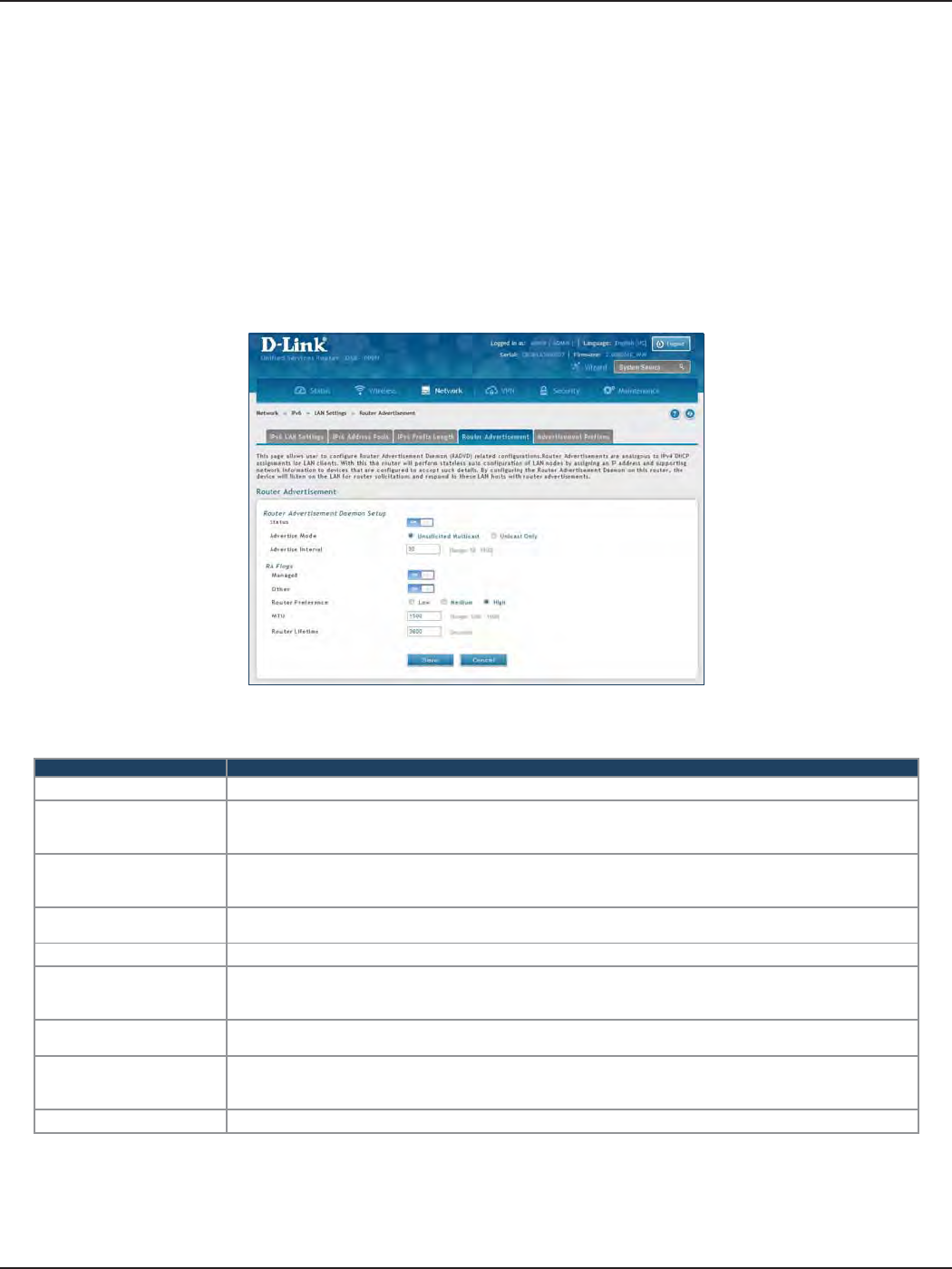
D-Link DSR-Series User Manual 77
Section 5 - Connect to the Internet
Router Advertisement
Path: Network > IPv6 > LAN Settings > Router Advertisement
To congure router advertisement settings:
1. Click Network > IPv6 > LAN Settings > Router Advertisement tab.
2. Complete the elds in the table on the next page and click Save.
Field Description
Status Toggle to ON to enable this feature.
Advertise Mode
Select Unsolicited Multicast to send router advertisements (RA’s) to all interfaces in the multicast group.
To restrict RA’s to well-known IPv6 addresses on the LAN, and thereby reduce overall network trac, select
Unicast only.
Advertise Interval
When advertisements are unsolicited multicast packets, this interval sets the maximum time between
advertisements from the interface. The actual duration between advertisements is a random value between
one third of this eld and this eld. The default is 30 seconds.
Managed Toggle to ON to use the administered/stateful protocol for address auto-conguration. If set to OFF, the
host uses administered/stateful protocol for non-address auto conguration.
Other Toggle to ON to use administered/stateful protocol of other (i.e., non-address) information auto conguration.
Router Preference
This parameter (low/medium/high) determines the preference associated with the RADVD process of the
router. This is useful if there are other RADVD-enabled devices on the LAN as it helps avoid conicts for IPv6
clients.
MTU The router advertisement will set this maximum transmission unit (MTU) value for all nodes in the LAN that
are auto-congured by the router. The default is 1500.
Router Lifetime
This value is present in RAs and indicates the usefulness of this router as a default router for the interface.
The default is 3600 seconds. Upon expiration of this value, a new RADVD exchange must take place between
the host and this router.
Save Click Save at the bottom to save and activate your settings.
Router Advertisements are analogous to IPv4 DHCP assignments for LAN clients, in that the router will assign
an IP address and supporting network information to devices that are congured to accept such details. Router
Advertisement is required in an IPv6 network is required for stateless auto conguration of the IPv6 LAN.
By conguring the Router Advertisement Daemon on this router, the router will listen on the LAN for router
solicitations and respond to these LAN hosts with router advisements.
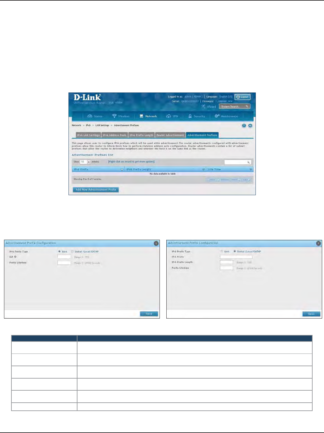
D-Link DSR-Series User Manual 78
Section 5 - Connect to the Internet
Advertisement Prexes
Path: Network > IPv6 > LAN Settings > Advertisement Prexes
To add, edit, or delete an advertisement prex entry:
1. Click Network > IPv6 > LAN Settings > Advertisement Prexes tab.
Router advertisements congured with advertisement prexes allow this router to inform hosts how to perform
stateless address auto conguration. Router advertisements contain a list of subnet prexes that allow the router
to determine neighbors and whether the host is on the same link as the router.
2. Right-click a current entry and select Edit or Delete. To add a new entry, click Add New Advertisement
Length.
3. Complete the elds in the table below and click Save.
Field Description
IPv6 Prex Type To ensure hosts support IPv6 to IPv4 tunnel select the 6to4 prex type. Selecting Global/Local/ISATAP will
allow the nodes to support all other IPv6 routing options.
SLA ID The SLA ID (Site-Level Aggregation Identier) is available when 6to4 Prexes are selected. This should be
the interface ID of the router’s LAN interface used for router advertisements.
IPv6 Prex When using Global/Local/ISATAP prexes, this eld is used to dene the IPv6 network advertised by this
router.
IPv6 Prex Length This value indicates the number contiguous, higher order bits of the IPv6 address that dene up the
network portion of the address. Typically this is 64.
Prex Lifetime This denes the duration (in seconds) that the requesting node is allowed to use the advertised prex. It
is analogous to DHCP lease time in an IPv4 network.
Save Click Save at the bottom to save and activate your settings.
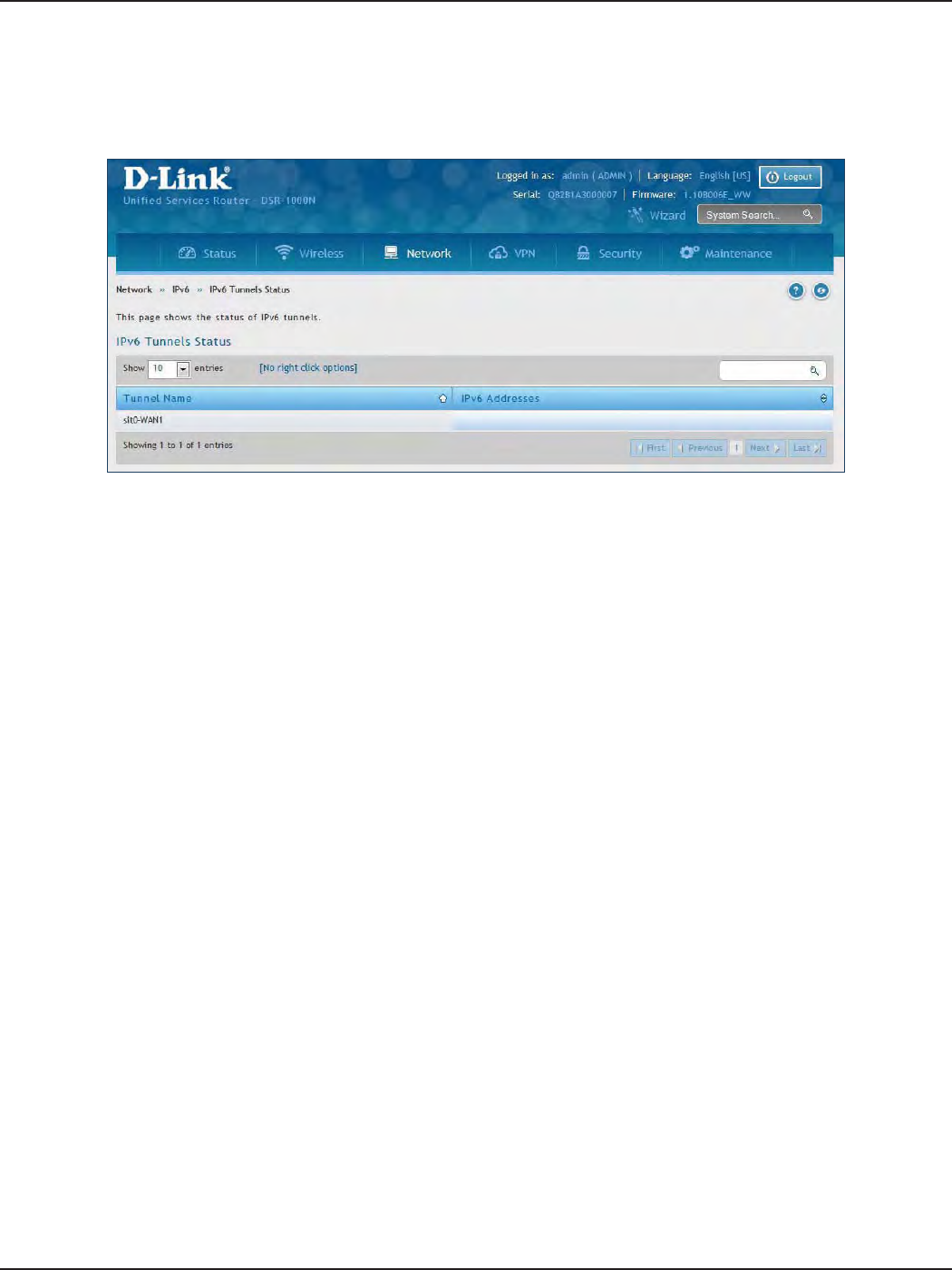
D-Link DSR-Series User Manual 79
Section 5 - Connect to the Internet
IPv6 Tunnels Status
Path: Network > IPv6 > IPv6 Tunnels Status
This page displays the current status of IPv6 Tunnels.
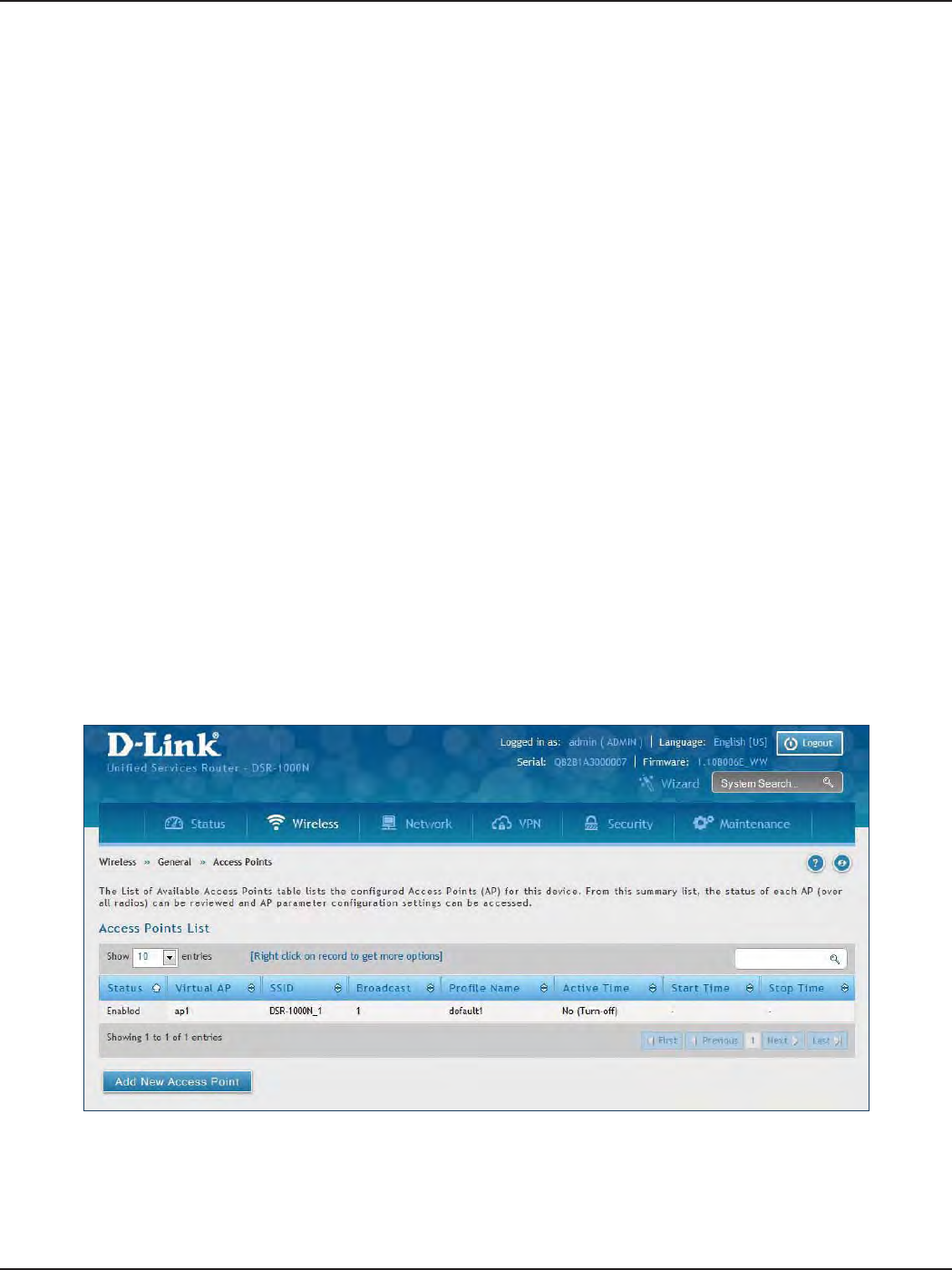
D-Link DSR-Series User Manual 80
Section 6 - Wireless Settings
Wireless Settings
Access Points
This router has an integrated 802.11n radio that allows you to create an access point for wireless LAN clients. The
security/encryption/authentication options are grouped in a wireless Prole, and each congured prole will be
available for selection in the AP conguration menu. The prole denes various parameters for the AP, including
the security between the wireless client and the AP, and can be shared between multiple APs instances on the
same device when needed.
Up to four unique wireless networks can be created by conguring multiple “virtual” APs . Each such virtual AP
appears as an independent AP (unique SSID) to supported clients in the environment, but is actually running on
the same physical radio integrated with this router.
Note: Proles may be thought of as a grouping of AP parameters that can then be applied to not just one but multiple
AP instances (SSIDs), thus avoiding duplication if the same parameters are to be used on multiple AP instances or SSIDs.
The Wireless Network Setup Wizard is available for users new to wireless networking. By going through a few
conguration pages you can enable a Wi-Fi™ network on your LAN and allow supported 802.11 clients to connect
to the congured Access Point. To run the wizard, refer to “#6 Wireless Network Setup” on page 12.
Path: Wireless > General > Access Points
To add, edit, or delete an access point entry:
1. Click Wireless > General > Access Points.
2. Right-click a current entry and select Edit or Delete. To add a new entry, click Add New Access Point.
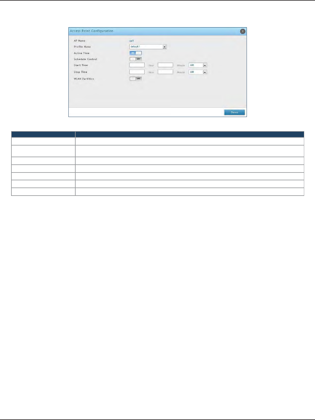
D-Link DSR-Series User Manual 81
Section 6 - Wireless Settings
3. Complete the elds in the table below and click Save.
Field Description
AP Name Enter a name for your virtual access point.
Prole Name Select a prole from the drop-down menu to associate this access point with. If you do not want to use the
default prole, create a prole (refer to the next page) and then create an access point.
Active Time Toggle to ON to “turn on” this access point.
Schedule Control Toggle to ON if you want to specify a time to have this access point turned on.
Start/Stop Time Enter a start and stop time.
WLAN Partition Toggle to ON to prevent associated wireless clients from communicating with each other.
Save Click Save at the bottom to save and activate your settings.
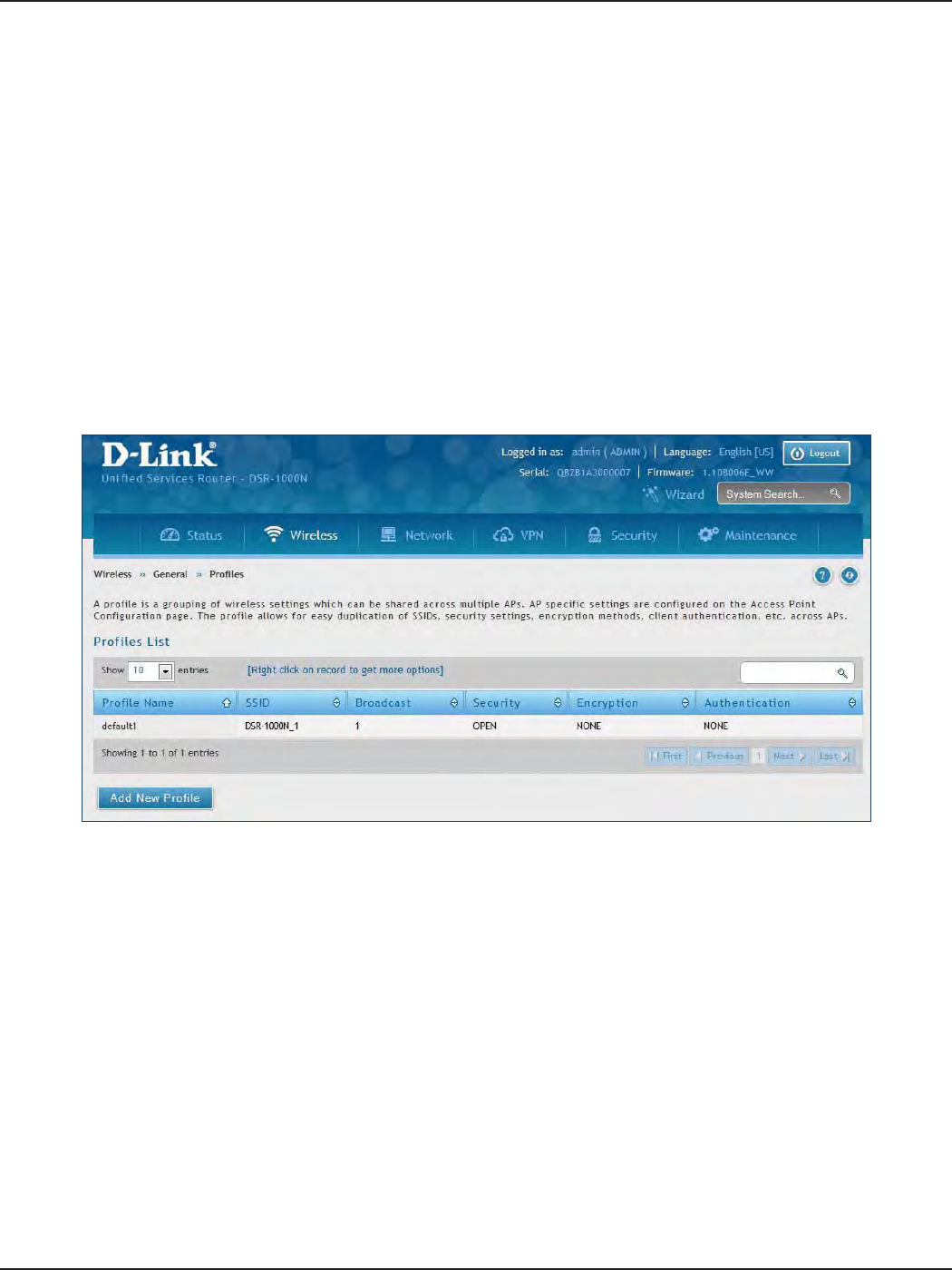
D-Link DSR-Series User Manual 82
Section 6 - Wireless Settings
Proles
Creating a prole allows you to assign the security type, encryption and authentication to use when connecting
the AP to a wireless client. The default mode is “open”, i.e., no security. This mode is insecure as it allows any
compatible wireless clients to connect to an AP congured with this security prole.
To create a new prole, use a unique prole name to identify the combination of settings. Congure a unique
SSID that will be the identier used by the clients to communicate to the AP using this prole. By choosing to
broadcast the SSID, compatible wireless clients within range of the AP can detect this prole’s availability. The AP
oers all advanced 802.11 security modes, including WEP, WPA, and WPA2.
To add, edit, or delete a prole:
1. Click Wireless > General > Proles.
Path: Wireless > General > Proles
2. Right-click a current entry and select Edit or Delete. To add a new entry, click Add New Access Point.
3. Complete the elds in the table on the next page and click Save.
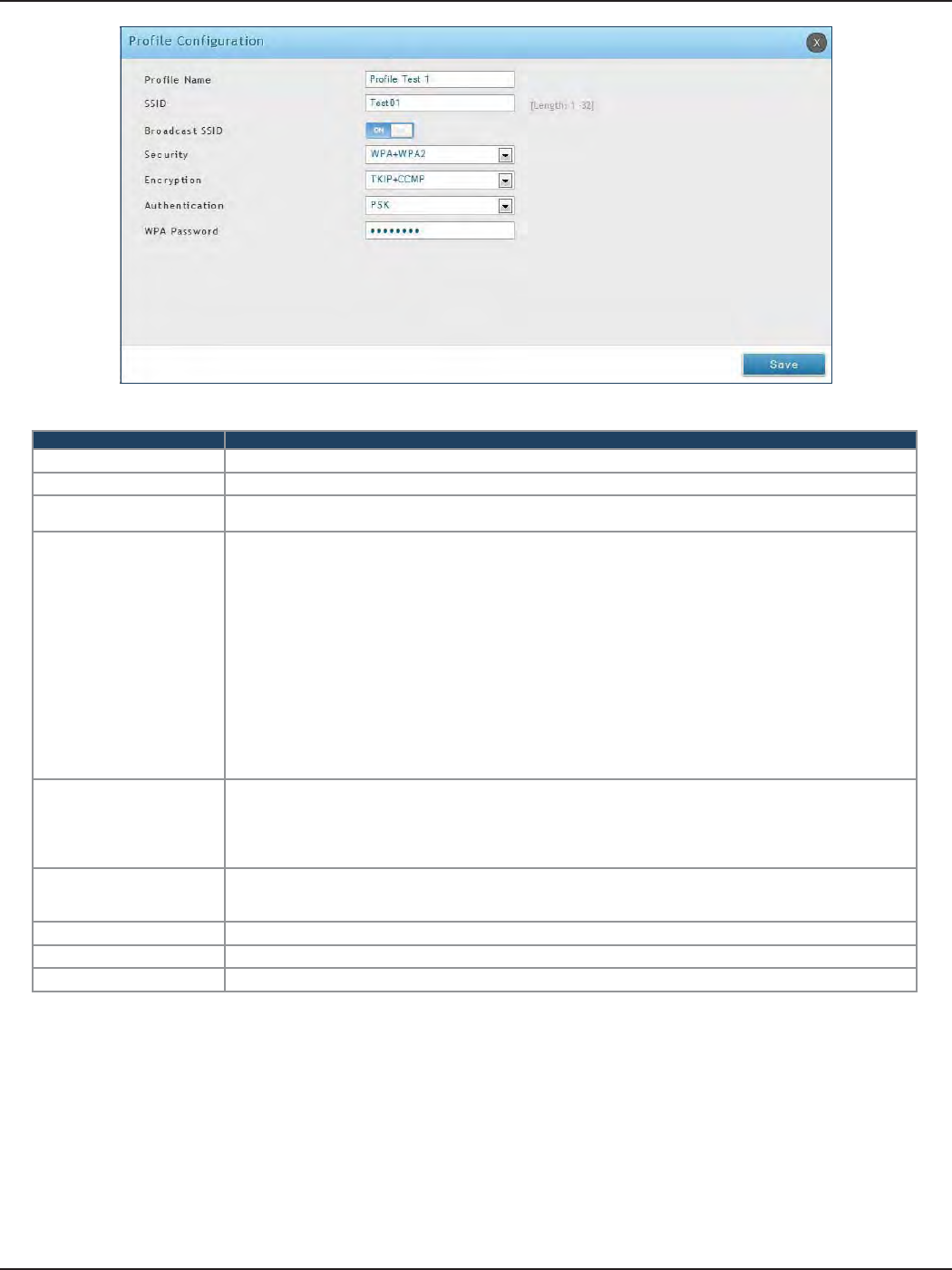
D-Link DSR-Series User Manual 83
Section 6 - Wireless Settings
Field Description
Prole Name Enter a name for your prole.
SSID Enter a name for your wireless network (SSID).
Broadcast SSID Toggle to ON if you want your SSID broadcast openly or toggle to OFF to hide it. Clients will have to know
the SSID to connect.
Security
Select what kind of wireless security you want to use:
• Open: Select this option to create a public “open” network to allow unauthenticated devices to access
this wireless gateway.
• WEP (Wired Equivalent Privacy): This option requires a static (pre -shared) key to be shared between
the AP and wireless client . Note that WEP does not support 802.11n data rates; is it appropriate for
legacy 802.11 connections.
• WPA (Wi-Fi Protected Access): For stronger wireless security than WEP, choose this option. The
encryption for WPA will use TKIP and also CCMP if required. The authentication can be a preshared
key (PSK), Enterprise mode with RADIUS server, or both. Note that WPA does not support 802.11n data
rates; is it appropriate for legacy 802.11 connections.
• WPA2: This security type uses CCMP encryption (and the option to add TKIP encryption) on either PSK
(pre-shared key) or Enterprise (RADIUS Server) authentication.
• WPA + WPA2: This uses both encryption algorithms, TKIP and CCMP. WPA clients will use TKIP and
WPA2 clients will use CCMP encryption algorithms.
Encryption
Select the encryption type:
• WEP - Select Open or Shared.
• WPA - Select TKIP or TKIP+CCMP.
• WPA2 - Select CCMP or TKIP+CCMP.
• WPA+WPA2 - TKIP+CCMP will be the only option.
Authentication
Select the authentication type:
• WEP - Select 64-bit or 128-bit.
• WPA/WPA2/WPA+WPA2 - Select PSK (passphrase), RADIUS (RADIUS server), or PSK+RADIUS (both).
WEP Passphrase/Key (1-4) If you selected WEP, enter a passphrase or up to four hexadecimal keys (a-f, 0-9, A-F).
WPA Password If you selected WPA, WPA2, or WPA+WPA2, enter a WPA password.
Save Click Save at the bottom to save and activate your settings.
The AP conguration page allows you to create a new AP and link to it one of the available proles. This router
supports multiple AP’s referred to as virtual access points (VAPs). Each virtual AP that has a unique SSIDs appears
as an independent access point to clients. This valuable feature allows the router’s radio to be congured in a way
to optimize security and throughput for a group of clients as required by the user. To create a VAP, refer to “Access
Points” on page 80. After setting the AP name, the prole drop-down menu is used to select one of the congured
proles.
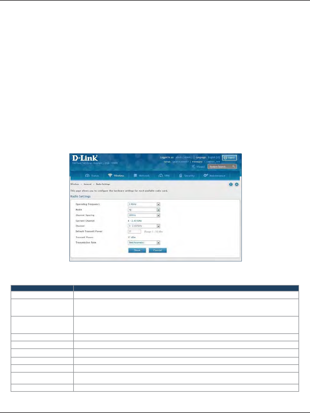
D-Link DSR-Series User Manual 84
Section 6 - Wireless Settings
Radio Settings
Path: Wireless > General > Radio Settings
You may congure the channels and power levels available for the AP’s enabled on the router. The router has a dual
band 802.11n radio, meaning either 2.4 GHz or 5 GHz frequency of operation can be selected (not concurrently
though). Based on the selected operating frequency, the mode selection will let you dene whether legacy
connections or only 802.11n connections (or both) are accepted on congured APs.
The ratied 802.11n support on this radio requires selecting the appropriate broadcast mode, and then dening
the channel spacing and control side band for 802.11n trac. The default settings are appropriate for most
networks. For example, changing the channel spacing to 40MHz can improve bandwidth at the expense of
supporting earlier 802.11n clients. The available transmission channels are governed by regulatory constraints
based on the region setting of the router.
To congure the radio settings:
1. Click Wireless > General > Radio Settings.
2. Complete the elds in the table below and click Save.
Field Description
Operating Frequency Select 2.4GHz or 5GHz.
Mode
Select the 802.11 mode:
• 2.4GHz - g and b, g only, n and g, or n only.
• 5GHz - a only, n and a, or n only.
Channel Spacing
Select the Channel Width:
Auto 20/40 - This is the default setting. Select if you are using both 802.11n and non-802.11n wireless devices.
20MHz - Select if you are not using any 802.11n wireless clients.
Control Side Band Select Upper or Lower. Available for 802.11n only.
Current Channel Displays the current channel.
Channel Select the channel you want to use.
Default Transmit Power Enter the default transmit power (0-31).
Transmit Power Displays the current transmit power.
Transmission Rate Select a transmission rate from the drop-down menu. This will lock the transmission rate of your wireless
connection. It is strongly recommended to use Best (Automatic).
Save Click Save at the bottom to save and activate your settings.
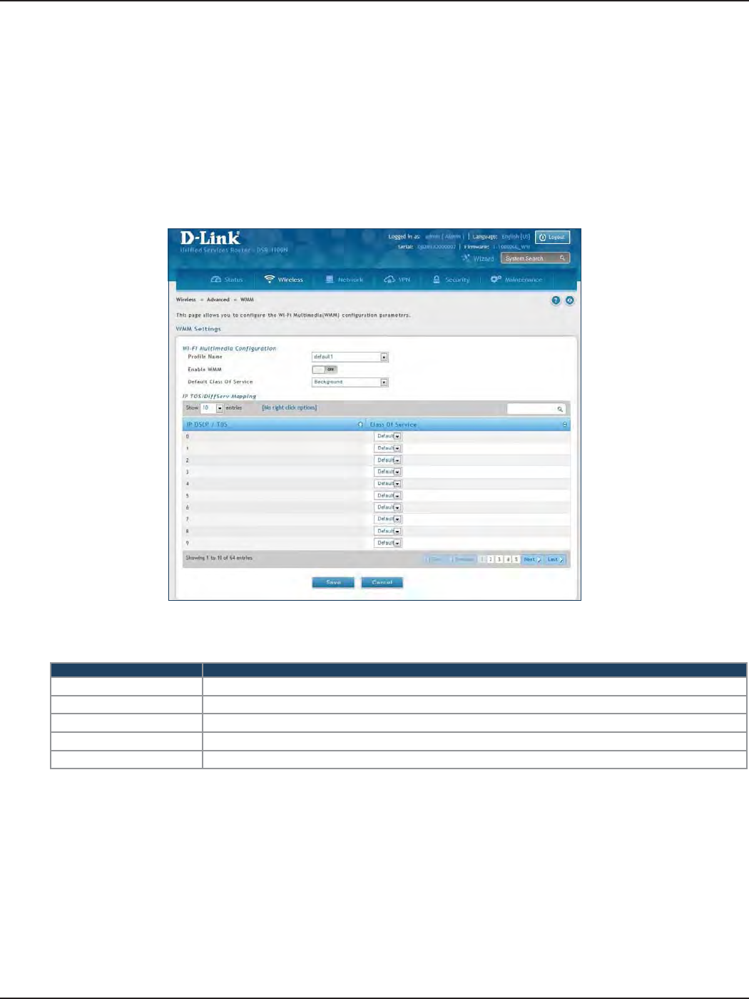
D-Link DSR-Series User Manual 85
Section 6 - Wireless Settings
WMM Settings
Path: Wireless > Advanced > WMM
Wi-Fi Multimedia (WMM) provides basic Quality of Service (QoS) features to IEEE 802.11 networks. WMM prioritizes
trac according to four Access Categories (AC) - voice, video, best eort, and background.
To congure the radio settings:
1. Click Wireless > Advanced > WMM.
2. Complete the elds in the table below and click Save.
Field Description
Prole Name Select the prole to associate this conguration to from the drop-down menu.
Enable WMM Toggle to ON to enable WMM.
Default Class of Service Select an available access category (voice, video, best eort, or background) to assign as “default”.
IP DSCP / TOS Under Class of Service, select a service and map it to the IP DSCP / TOS value.
Save Click Save at the bottom to save and activate your settings.
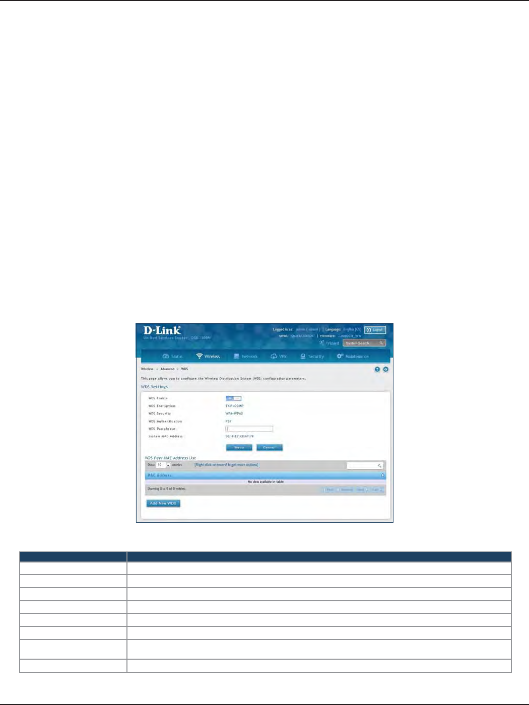
D-Link DSR-Series User Manual 86
Section 6 - Wireless Settings
WDS
Path: Wireless > Advanced > WDS
Wireless Distribution System (WDS) is a system enabling the wireless interconnection of access points in a
network. This feature is only guaranteed to work between devices of the same type (i.e., using the same chipset/
driver).
When you enable WDS, use the same security conguration as the default access point. The WDS links do not
have true WPA/WPA2 support, as in there is no WPA key handshake performed. Instead the Session Key to be
used with a WDS Peer is computed using a hashing function (similar to the one used for computing a WPA PMK).
The inputs to this function are a PSK (congurable by an administrator from the WDS page) and an internal
“magic” string (non-congurable).
In eect the WDS links use TKIP/AES encryption, depending on the encryption congured for the default AP. In
case the default AP uses mixed encryption (TKIP + AES). The WDS link will use the AES encryption scheme.
Note: For a WDS link to function properly the Radio settings on the WDS peers have to be the same.
To congure the radio settings:
1. Click Wireless > Advanced > WDS.
2. Complete the elds in the table below and click Save.
Field Description
WDS Enable Toggle to ON to enable WDS and click Save.
WDS Encryption Displays the current wireless encryption used.
WDS Security Displays the current security type.
WDS Authentication Displays the current authentication type.
WDS Passphrase Enter the WDS passphrase (if WEP, WPA, WPA2, or WPA+WPA2 is enabled).
System MAC Address Displays the system MAC address.
Add New WDS Once you enabled WDS (and clicked Save), click Add New WDS and enter the MAC address of a WDS peer.
You can add up to four WDS peers.
Save Click Save at the bottom to save and activate your settings.
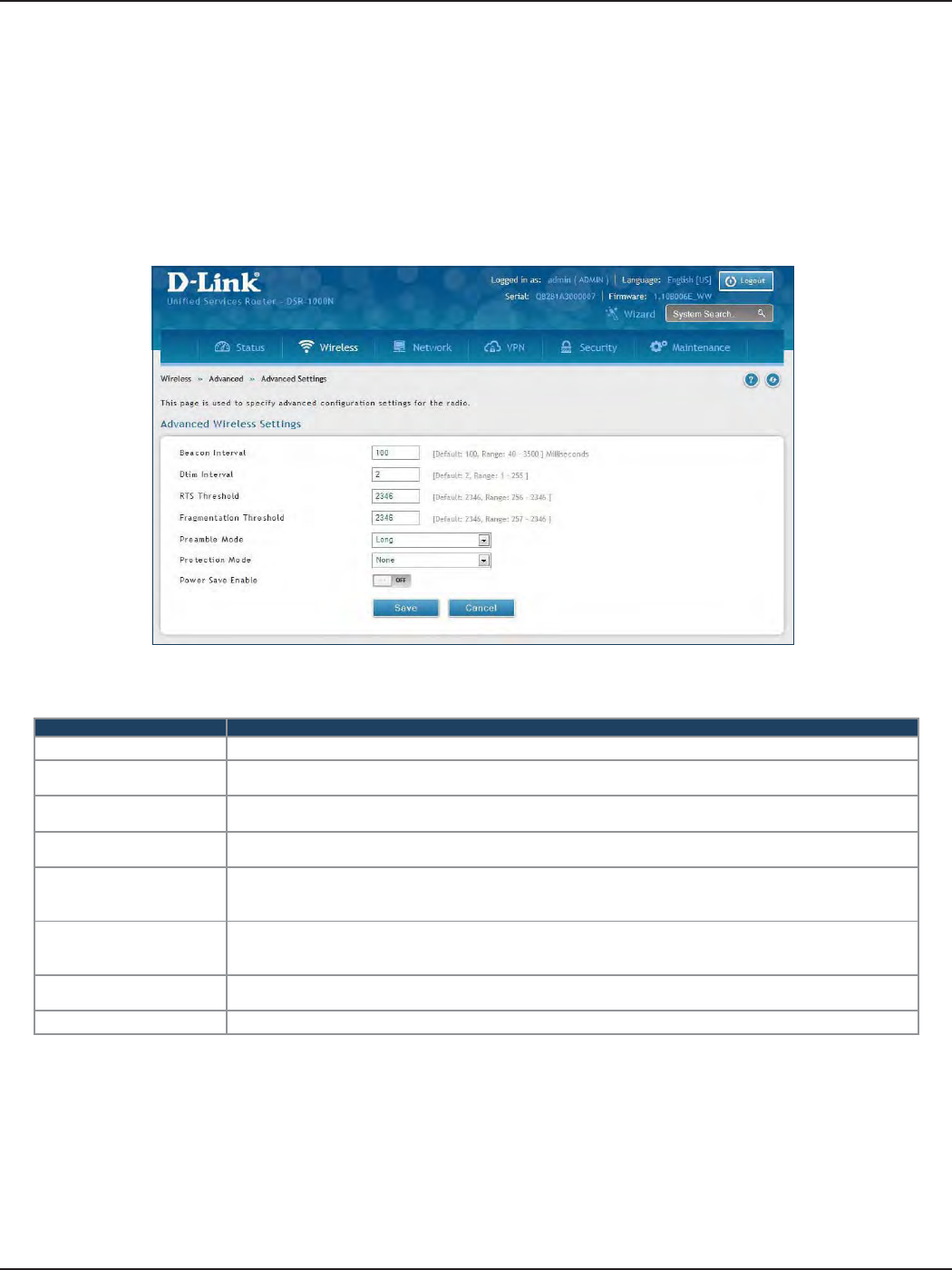
D-Link DSR-Series User Manual 87
Section 6 - Wireless Settings
Advanced Settings
Path: Wireless > Advanced > Advanced Settings
You can modify the 802.11 communication parameters in this page. Generally, the default settings are appropriate
for most networks.
Field Description
Beacon Interval Beacons are packets sent by an Access Point to synchronize a wireless network. The default value is 100.
DTIM Interval (Delivery Trac Indication Message) 3 is the default setting. A DTIM is a countdown informing clients of the
next window for listening to broadcast and multicast messages.
RTS Threshold This value should remain at its default setting of 2432. If inconsistent data ow is a problem, only a minor
modication should be made.
Fragmentation Threshold The fragmentation threshold, which is specied in bytes, determines whether packets will be fragmented.
Packets exceeding the 2346 byte setting will be fragmented before transmission. 2346 is the default setting.
Preamble Mode
Select either Long or Short. The Preamble Type denes the length of the CRC (Cyclic Redundancy Check)
block for communication between the Access Point and roaming wireless adapters. High network trac
areas should use Short preamble type.
Protection Mode
Select either None or CTS-to-Self Protection. Select the CTS-to-Self Protection to enable CTS-to-Self
protection mechanism, which is used to minimize collisions among stations in a mixed 802.11b & g
environment. The default selection is None.
Power Save Enable Toggle to ON to enable the Unscheduled Automatic Power Save Delivery (also referred to as WMM Power
Save) feature that allows the radio to conserve power.
Save Click Save at the bottom to save and activate your settings.
1. Click Wireless > Advanced > Advanced Settings.
2. Complete the elds in the table below and click Save.
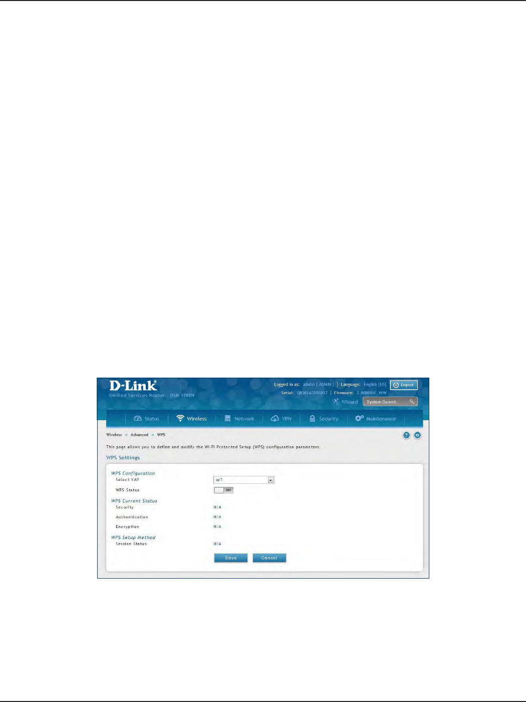
D-Link DSR-Series User Manual 88
Section 6 - Wireless Settings
WPS
Path: Wireless > Advanced > WPS
WPS is a simplied method to add supporting wireless clients to the network. WPS is only applicable for APs that
employ WPA or WPA2 security. To use WPS, select the eligible VAPs from the drop-down menu of APs that have
been congured with this security and enable WPS status for this AP.
The WPS Current Status section outlines the security, authentication, and encryption settings of the selected AP.
These are consistent with the AP’s prole. There are two setup options:
• Personal Identication Number (PIN): The wireless device that supports WPS may have an
alphanumeric PIN, if it does add the PIN in this eld. The router will connect within 60 seconds
of clicking the “Congure via PIN” button immediately below the PIN eld. There is no LED
indication that a client has connected.
• Push Button Conguration (PBC): For wireless devices that support PBC, press and hold the
WPS button for two seconds, and then press the WPS button (or initiate WPS via GUI) on your
wireless client within two minutes. The AP will detect the wireless device and establish a secure
link to the client.
To enable and connect clients using WPS:
1. Click Wireless > Advanced > WPS.
2. Select which VAP you want to perform the WPS process from the drop-down menu.
3. Toggle WPS Status to ON and click Save.
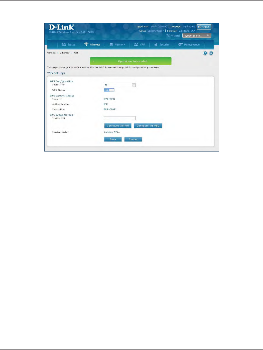
D-Link DSR-Series User Manual 89
Section 6 - Wireless Settings
4. Once enabled the following screen will appear.
5. Under WPS Setup Method, decide to either use PIN or PBC (Push Button).
6. If you want to use PIN method, enter the PIN next to Station PIN and click Congure Via PIN. You will
need to enter the PIN on your wireless client and start the WPS process within one minute.
7. If you want to use push button method, click Congure Via PBC. This will initiate the WPS session. You
will need to press the WPS button (or initiate through an interface) on your client within one minute.
8. Allow up to two minutes to connect. Check the Session Status to see if it successfully connected.

D-Link DSR-Series User Manual 90
Section 7 - VPN
VPN
A VPN provides a secure communication channel (“tunnel”) between two gateway routers or a remote PC client.
The following types of tunnels can be created:
• Gateway-to-gateway VPN: To connect two or more routers to secure trac between remote
sites.
• Remote Client (client-to-gateway VPN tunnel): A remote client initiates a VPN tunnel as the
IP address of the remote PC client is not known in advance. The gateway in this case acts as a
responder.
• Remote client behind a NAT router: The client has a dynamic IP address and is behind a NAT
Router. The remote PC client at the NAT router initiates a VPN tunnel as the IP address of the
remote NAT router is not known in advance. The gateway WAN port acts as responder.
• PPTP server for LAN / WAN PPTP client connections.
• L2TP server for LAN / WAN L2TP client connections.
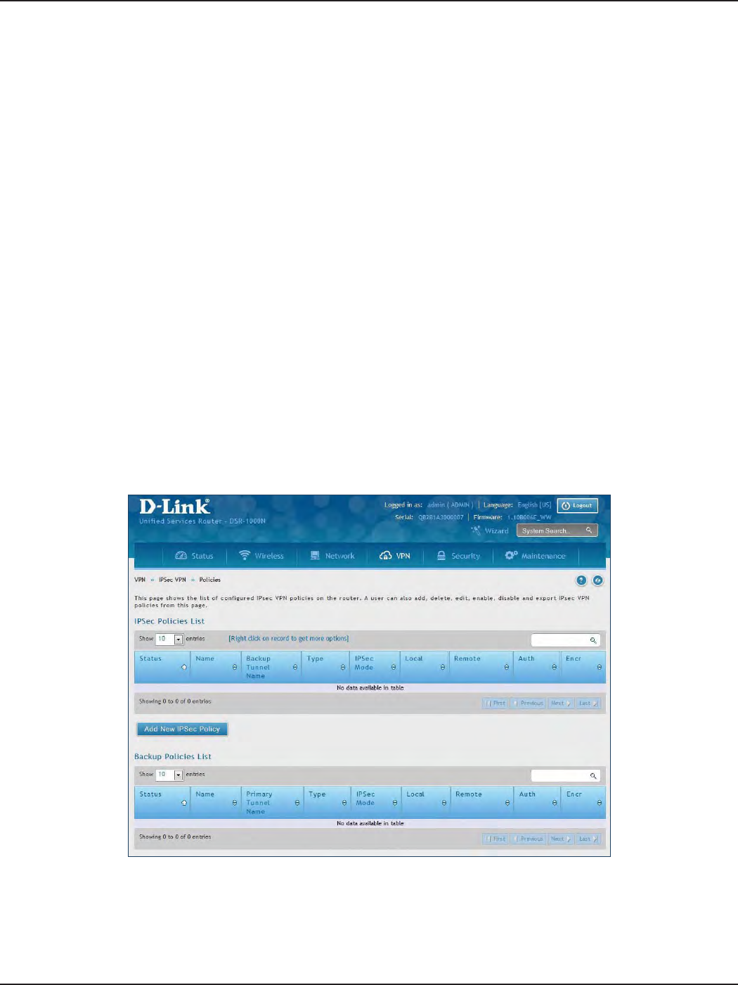
D-Link DSR-Series User Manual 91
Section 7 - VPN
IPSec VPN
Policies
Path: VPN > IPSec VPN > Policies
An IPsec policy is between this router and another gateway or this router and an IPsec client on a remote host.
The IPsec mode can be either tunnel or transport depending on the network being traversed between the two
policy endpoints.
• Transport: This is used for end-to-end communication between this router and the tunnel
endpoint, either another IPsec gateway or an IPsec VPN client on a host. Only the data payload
is encrypted and the IP header is not modied or encrypted.
• Tunnel: This mode is used for network-to-network IPsec tunnels where this gateway is one
endpoint of the tunnel. In this mode the entire IP packet including the header is encrypted
and/or authenticated.
When tunnel mode is selected, you can enable NetBIOS and DHCP over IPsec. DHCP over IPsec allows this router
to serve IP leases to hosts on the remote LAN. As well in this mode you can dene the single IP address, range of
IPs, or subnet on both the local and remote private networks that can communicate over the tunnel.
To congure the radio settings:
1. Click VPN > IPSec VPN > Policies.
2. Click Add new IPSec Policy. Fill out the General section which you will name the VPN, select policy
type, dene the tunnel type, and dene endpoints.
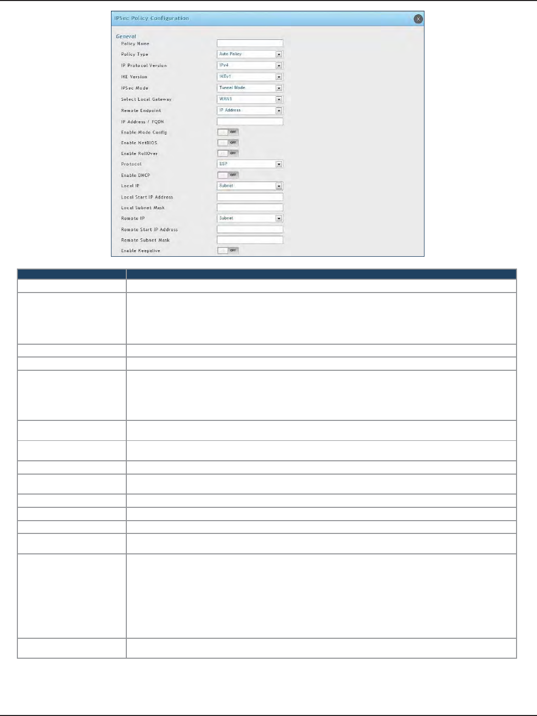
D-Link DSR-Series User Manual 92
Section 7 - VPN
Field Description
Policy Name Enter a unique name for the VPN Policy. This name is not an identier for the remote WAN/client.
Policy Type
Select either Manual or Auto.
• Manual: All settings (including the keys) for the VPN tunnel are manually input for each end point. No
third-party server or organization is involved.
• Auto: Some parameters for the VPN tunnel are generated automatically. This requires using the IKE
(Internet Key Exchange) protocol to perform negotiations between the two VPN Endpoints.
IP Protocol Version Select either IPv4 or IPv6.
IKE Version Select the version of IKE.
IPSec Mode
Select either Tunnel or Transport. IPsec tunnel mode is useful for protecting trac between dierent
networks, when trac must pass through an intermediate, untrusted network. Tunnel mode is primarily
used for interoperability with gateways, or end-systems that do not support L2TP/IPsec or PPTP connections.
Transport mode is the default mode for IPsec, and it is used for end-to-end communications (for example, for
communications between a client and a server).
Select Local Gateway In the event that two WAN ports are congured to connect to your ISP, select the gateway that will be used
as the local endpoint for this IPsec tunnel.
Remote Endpoint Select the type of identier that you want to provide for the router at the remote endpoint (either IP Address
or FQDN [Fully Qualied Domain Name])
IP Address/FQDN Enter the identier for the router.
Enable Mode Cong Toggle to ON to enable. Mode Cong is similar to DHCP and is used to assign IP addresses to the remote
VPN clients.
Enable NetBIOS Toggle to ON to allow NetBIOS broadcasts to travel over the VPN tunnel
Enable RollOver Toggle to ON to enable VPN rollover. You must have the WAN Mode set to Rollover.
Protocol Select a protocol from the drop-down menu.
Enable DHCP Toggle to ON to allow VPN clients that are connected to your router over IPsec to receive an assigned IP
using DHCP.
Local IP/Remote IP
Select the type of identier that you want to provide for the endpoint:
• Any: Species that the policy is for trac from the given end point (local or remote). Note that selecting
Any for both local and remote end points is not valid.
• Single: Limits the policy to one host. Enter the IP address of the host that will be part of the VPN.
• Range: Allows computers within an IP address range to connect to the VPN. Enter the Start IP Address
and End IP Address in the provided elds.
• Subnet: Allows an entire subnet to connect to the VPN. Enter the network address and subnet mask in
the provided elds.
Enable Keepalive Toggle to ON to periodically send ping packets to the host on the peer side of the network to keep the
tunnel alive.
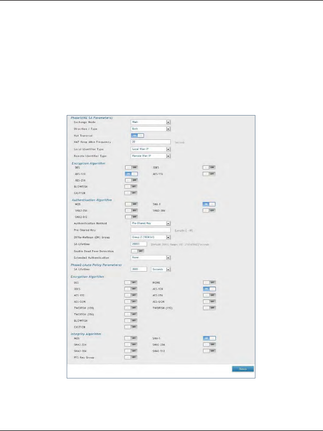
D-Link DSR-Series User Manual 93
Section 7 - VPN
3. Once the tunnel type and endpoints of the tunnel are dened you can determine the Phase 1/ Phase
2 negotiation to use for the tunnel. This is covered in the IPsec mode setting, as the policy can be
Manual or Auto. For Auto policies, the Internet Key Exchange (IKE) protocol dynamically exchanges
keys between two IPsec hosts. The Phase 1 IKE parameters are used to dene the tunnel’s security
association details.
The Phase 2 Auto policy parameters cover the security association lifetime and encryption/authentication
details of the phase 2 key negotiation.
The VPN policy is one half of the IKE/VPN policy pair required to establish an Auto IPsec VPN tunnel. The
IP addresses of the machine or machines on the two VPN endpoints are congured here, along with
the policy parameters required to secure the tunnel.

D-Link DSR-Series User Manual 94
Section 7 - VPN
A Manual policy does not use IKE and instead relies on manual keying to exchange authentication
parameters between the two IPsec hosts. The incoming and outgoing security parameter index
(SPI) values must be mirrored on the remote tunnel endpoint. As well the encryption and integrity
algorithms and keys must match on the remote IPsec host exactly in order for the tunnel to establish
successfully. Note that using Auto policies with IKE are preferred as in some IPsec implementations the
SPI (security parameter index) values require conversion at each endpoint.
DSR routers supports VPN roll-over feature. This means that policies congured on the primary WAN
will rollover to the secondary WAN in case of a link failure. This feature can be used only if your WAN is
congured in Auto-Rollover mode.
Note: Once you have created an IPSec policy, you may right-click the policy and select Export to save
as a le. You can then upload this to another DSR router or keep as a backup. To upload a saved policy,
refer to “Easy VPN Setup” on page 101.
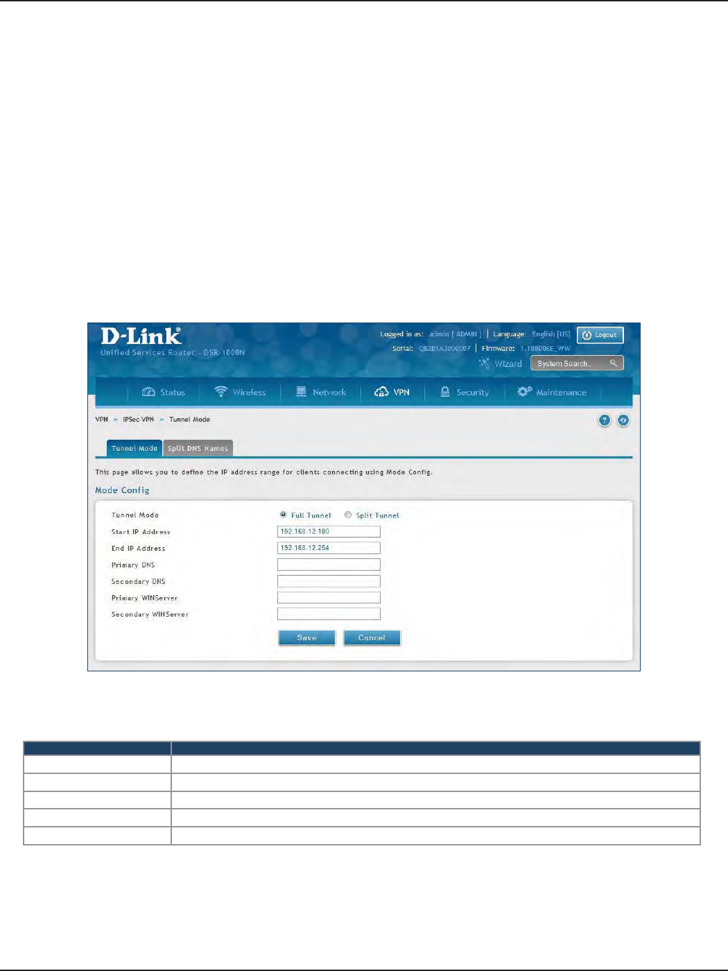
D-Link DSR-Series User Manual 95
Section 7 - VPN
Tunnel Mode
Path: VPN > IPSec VPN > Tunnel Mode
When tunnel mode is selected, you can enable NetBIOS and DHCP over IPSec. DHCP over IPSec allows this router
to serve IP leases to hosts on the remote LAN. You can also dene a single IP address, a range of IPs, or a subnet
on both the local and remote private networks that can communicate over the tunnel.
The router allows full tunnel and split tunnel support. Full tunnel mode just sends all trac from the client across
the VPN tunnel to the router. Split tunnel mode only sends trac to the private LAN based on pre-specied client
routes. These client routes give the client access to specic private networks, thereby allowing access control
over specic LAN services.
1. Click VPN > IPSec VPN > Tunnel Mode.
2. Complete the elds in the table below and click Save.
Field Description
Tunnel Mode Select either Full Tunnel or Split Tunnel.
Start/End IP Address Enter the starting and ending IP addresses.
Primary/Secondary DNS Enter the primary and secondary DNS server addresses.
Primary/Secondary WINS Enter the primary and secondary WINS server addresses.
Save Click Save to save and activate your settings.
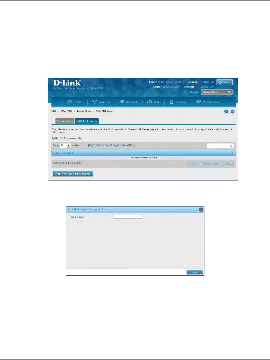
D-Link DSR-Series User Manual 96
Section 7 - VPN
Split DNS Names
To add a DNS name:
1. Click VPN > IPSec VPN > Tunnel Mode > Split DNS Names tab.
2. Click Add New Split DNS name. You can right-click any created entries to edit or delete.
3. Enter a domain name and click Save.
In a split DNS infrastructure, you create two zones for the same domain, one to be used by the internal network,
the other used by the external network. Split DNS directs internal hosts to an internal domain name server for
name resolution and external hosts are directed to an external domain name server for name resolution.
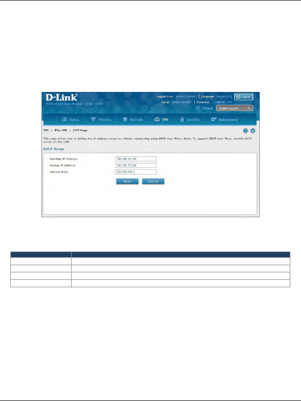
D-Link DSR-Series User Manual 97
Section 7 - VPN
DHCP Range
To congure the DHCP over IPSec DHCP server settings:
1. Click VPN > IPSec VPN > DHCP Range.
2. Complete the elds in the table below and click Save.
Field Description
Starting IP Address Enter the starting IP address to issue your clients connecting using DHCP over IPSec.
Ending IP Address Enter the ending IP address.
Subnet Mask Enter the subnet mask.
Save Click Save to save and activate your settings.
This page displays the IP range to be assigned to clients connecting using DHCP over IPsec. By default the range
is in 192.168.12.0 subnet.
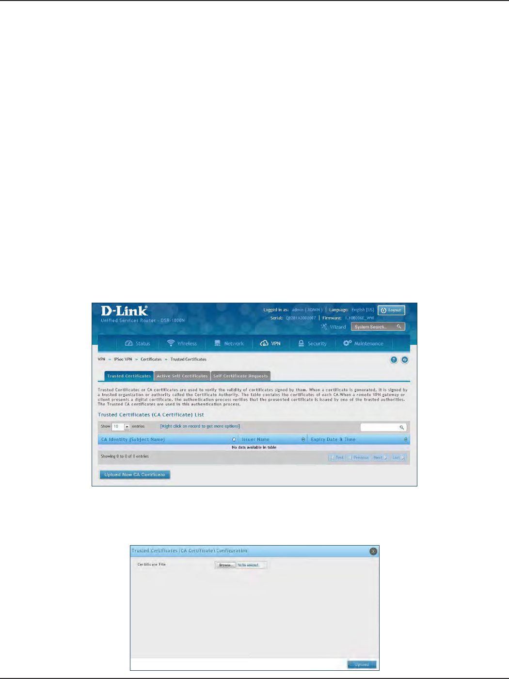
D-Link DSR-Series User Manual 98
Section 7 - VPN
Certicates
Trusted Certicates
This router uses digital certicates for IPsec VPN authentication. You can obtain a digital certicate from a well-
known Certicate Authority (CA) such as VeriSign, or generate and sign your own certicate using functionality
available on this gateway.
The router comes with a self-signed certicate, and this can be replaced by one signed by a CA as per your
networking requirements. A CA certicate provides strong assurance of the server’s identity and is a requirement
for most corporate network VPN solutions.
The certicates menu allows you to view a list of certicates (both from a CA and self-signed) currently loaded on
the router. The following certicate data is displayed in the list of Trusted (CA) certicates:
CA Identity (Subject Name): The certicate is issued to this person or organization
Issuer Name: This is the CA name that issued this certicate
Expiry Time: The date after which this Trusted certicate becomes invalid
To upload a certicate:
1. Click VPN > IPSec VPN > Certicate > Trusted Certicates tab.
2. Click the Browse button. Locate your certicate and click Open.
3. Click Upload.
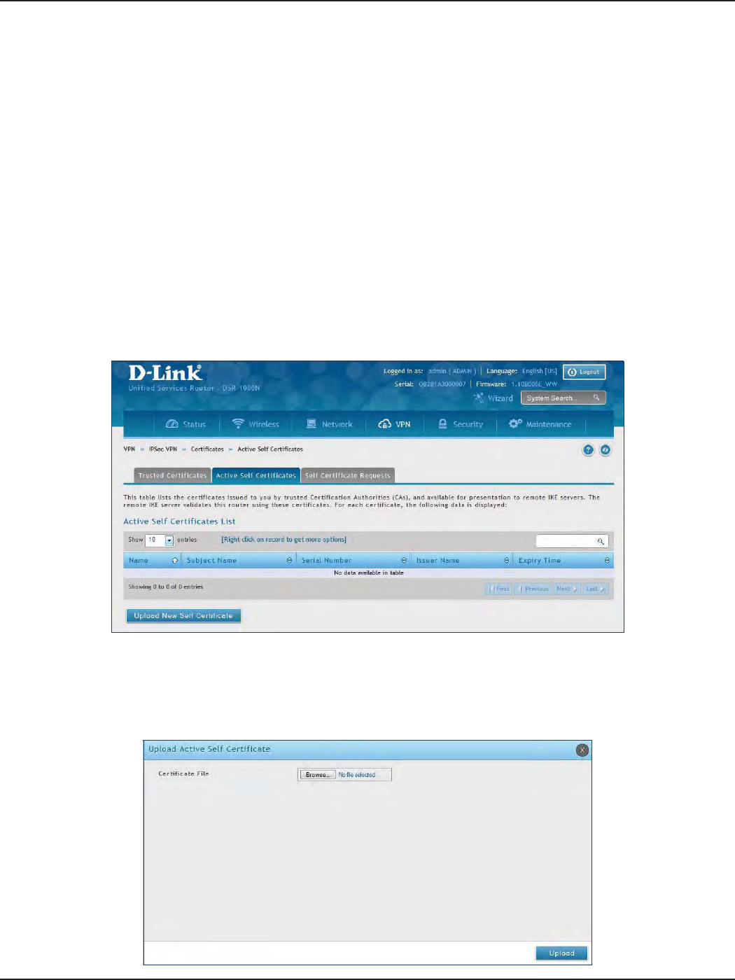
D-Link DSR-Series User Manual 99
Section 7 - VPN
Active Self Certicates
A self certicate is a certicate issued by a CA identifying your device (or self-signed if you don’t want the identity
protection of a CA). The Active Self Certicate table lists the self certicates currently loaded on the router. The
following information is displayed for each uploaded self certicate:
Name: The name you use to identify this certicate, it is not displayed to IPsec VPN peers.
Subject Name: This is the name that will be displayed as the owner of this certicate. This should be your
ocial registered or company name, as IPsec or SSL VPN peers are shown this eld.
Serial Number: The serial number is maintained by the CA and used to identify this signed certicate.
Issuer Name: This is the CA name that issued (signed) this certicate
Expiry Time: The date after which this signed certicate becomes invalid. You should renew the certicate
before it expires.
To upload a certicate:
1. Click VPN > IPSec VPN > Certicate > Active Self Certicates tab.
2. Click the Browse button. Locate your certicate and click Open.
3. Click Upload.
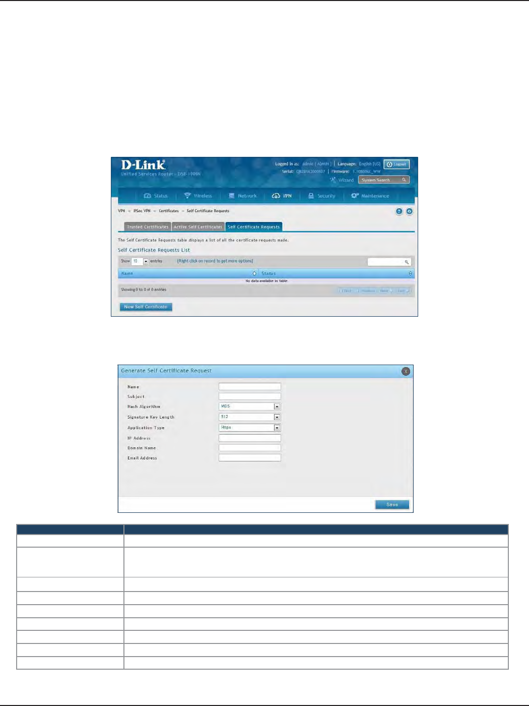
D-Link DSR-Series User Manual 100
Section 7 - VPN
Self Certicate Requests
To request a self certicate to be signed by a CA, you can generate a Certicate Signing Request from the router
by entering identication parameters and passing it along to the CA for signing. Once signed, the CA’s Trusted
Certicate and signed certicate from the CA are uploaded to activate the self -certicate validating the identity
of this gateway. The self certicate is then used in IPsec and SSL connections with peers to validate the gateway’s
authenticity.
To generate a certicate signing request:
1. Click VPN > IPSec VPN > Certicates > Self Certicate Requests.
2. Click New Self Certicate.
3. Complete the elds in the table below and click Save.
Field Description
Name Enter a name (identier) for the certicate.
Subject
This eld will populate the CN (Common Name) entry of the generated certicate. Subject names are usually
dened in the following format: CN=<device name>, OU=<department>, O=<organization>, L=<city>,
ST=<state>, C=<country>. For example: CN=router1, OU=my_company, O=mydept, L=SFO, C=US.
Hash Algorithm Select the algorithm from the drop-down menu. Select either MD5 or SHA-1.
Signature Key Length Select the signature key length from the drop-down menu. Select either 512, 1024, or 2048
Application Type Select the application type from the drop-down menu. Select either HTTPS or IPSec.
IP Address Enter an IP address (optional).
Domain Name Enter a domain name (optional).
Email Address Enter your email address.
Save Click Save to save and activate your settings.
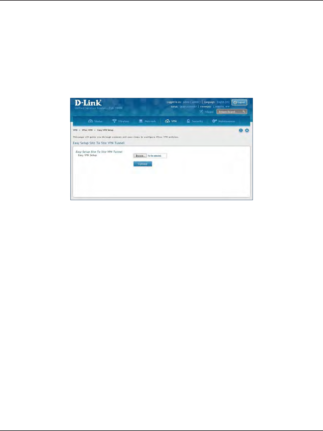
D-Link DSR-Series User Manual 101
Section 7 - VPN
Easy VPN Setup
To upload an exported IPSec VPN policy:
1. Click VPN > IPSec VPN > Easy VPN Setup.
2. Click Browse and navigate to the policy le you want to upload. Select it and click Open.
3. Click Upload.
4. Once uploaded, go to VPN > IPSec VPN > Policies and the loaded VPN will be listed. Right-click it to
edit or delete.
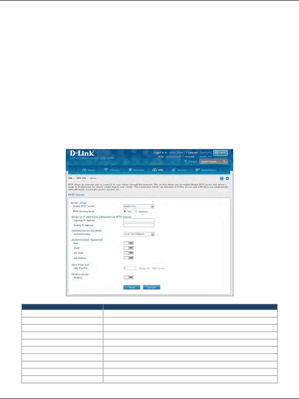
D-Link DSR-Series User Manual 102
Section 7 - VPN
PPTP VPN
Server
Path: VPN > PPTP VPN > Server
A PPTP VPN can be established through this router. Once enabled a PPTP server is available on the router for LAN
and WAN PPTP client users to access. Once the PPTP server is enabled, PPTP clients that are within the range of
congured IP addresses of allowed clients can reach the router’s PPTP server. Once authenticated by the PPTP
server (the tunnel endpoint), PPTP clients have access to the network managed by the router.
The range of IP addresses allocated to PPTP clients can coincide with the LAN subnet. As well the PPTP server
will default to local PPTP user authentication, but can be congured to employ an external authentication server
should one be congured.
Field Description
Enable PPTP Server Select either IPv4 or IPv6.
PPTP Routing Mode Select either NAT or Classical.
Starting/Ending IP Address Enter the IP address range to assign your PPTP clients.
IPv6 Prex If you selected IPv6, enter the IPv6 prex.
IPv6 Prex Length If you selected IPv6, enter the IPv6 prex length.
Authentication Select the authentication type from the drop-down menu.
Authentication Supported Toggle which type of authentication you want to enable to ON.
Idle TimeOut Enter the amount of time in seconds that the connection will disconnect when idle.
NetBIOS Toggle to ON to allow NetBIOS broadcasts to travel over the VPN tunnel.
Save Click to save your settings.
To create a PPTP VPN server:
1. Click VPN > PPTP VPN > Server.
2. Complete the elds in the table below and click Save.
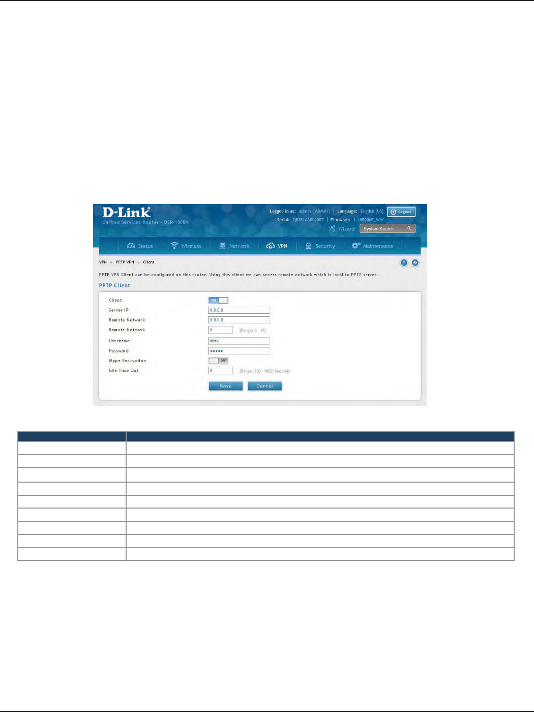
D-Link DSR-Series User Manual 103
Section 7 - VPN
Client
Path: VPN > PPTP VPN > Client
PPTP VPN Client can be congured on this router. Using this client you can access remote network which is
local to PPTP server. Once client is enabled, the user can access Status > Active VPNs page and establish PPTP
VPN tunnel clicking Connect.
Field Description
Client Toggle to ON to enable PPTP client.
Server IP Enter the IP address of the PPTP server you want to connect to.
Remote Network Enter the remote network address. This address is local for the PPTP Server.
Remote Netmask Enter the remote network subnet mask.
Username Enter your PPTP user name.
Password Enter your PPTP password.
MPPE Encryption Toggle to ON to enable Microsoft Point-to-Point Encryption (MPPE).
Idle Time Out Enter the amount of time (in seconds) that you will disconnect from the PPTP server when idle.
Save Click Save to save and activate your settings.
To congure the router as a PPTP VPN client:
1. Click VPN > PPTP VPN > Client tab.
2. Toggle Client to ON and complete the elds in the table below.
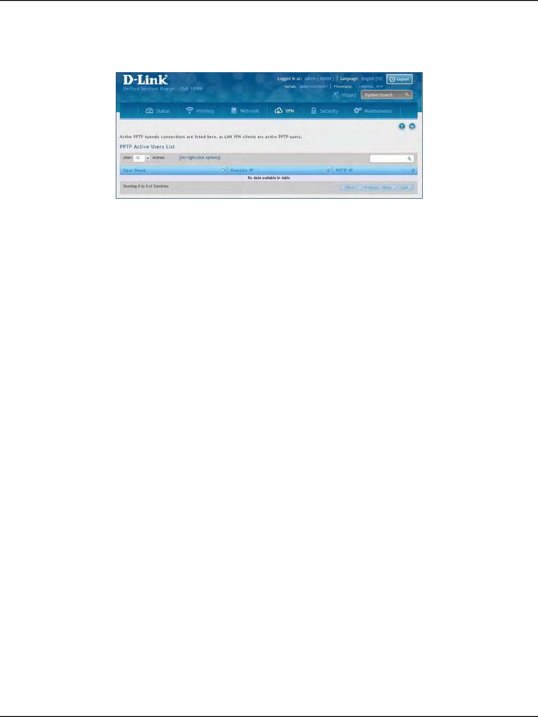
D-Link DSR-Series User Manual 104
Section 7 - VPN
PPTP Active Users List
A list of PPTP connections will be displayed on this page. Right-click the connection to connect and disconnect.
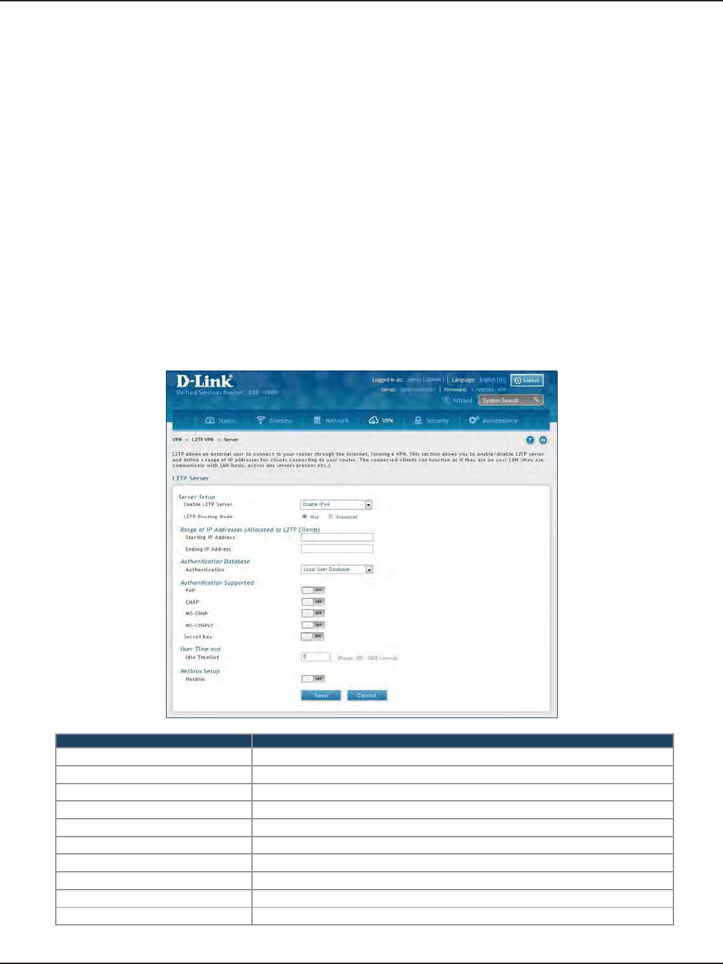
D-Link DSR-Series User Manual 105
Section 7 - VPN
L2TP VPN
Server
Path: VPN > L2TP VPN > Server
A L2TP VPN can be established through this router. Once enabled a L2TP server is available on the router for LAN
and WAN L2TP client users to access. Once the L2TP server is enabled, PPTP clients that are within the range of
congured IP addresses of allowed clients can reach the router’s L2TP server. Once authenticated by the L2TP
server (the tunnel endpoint), L2TP clients have access to the network managed by the router.
The range of IP addresses allocated to L2TP clients can coincide with the LAN subnet. As well the L2TP server
will default to local L2TP user authentication, but can be congured to employ an external authentication server
should one be congured.
Field Description
Enable L2TP Server Select either IPv4 or IPv6.
L2TP Routing Mode Select either NAT or Classical.
Starting/Ending IP Address Enter the IP address range to assign your L2TP clients.
IPv6 Prex If you selected IPv6, enter the IPv6 prex.
IPv6 Prex Length If you selected IPv6, enter the IPv6 prex length.
Authentication Select the authentication type from the drop-down menu.
Authentication Supported Toggle which type of authentication you want to enable to ON.
Idle TimeOut Enter the amount of time in seconds that the connection will disconnect when idle.
NetBIOS Toggle to ON to allow NetBIOS broadcasts to travel over the VPN tunnel.
Save Click to save your settings.
To create a L2TP VPN server:
1. Click VPN >L2TP VPN > Server.
2. Complete the elds in the table below and click Save.
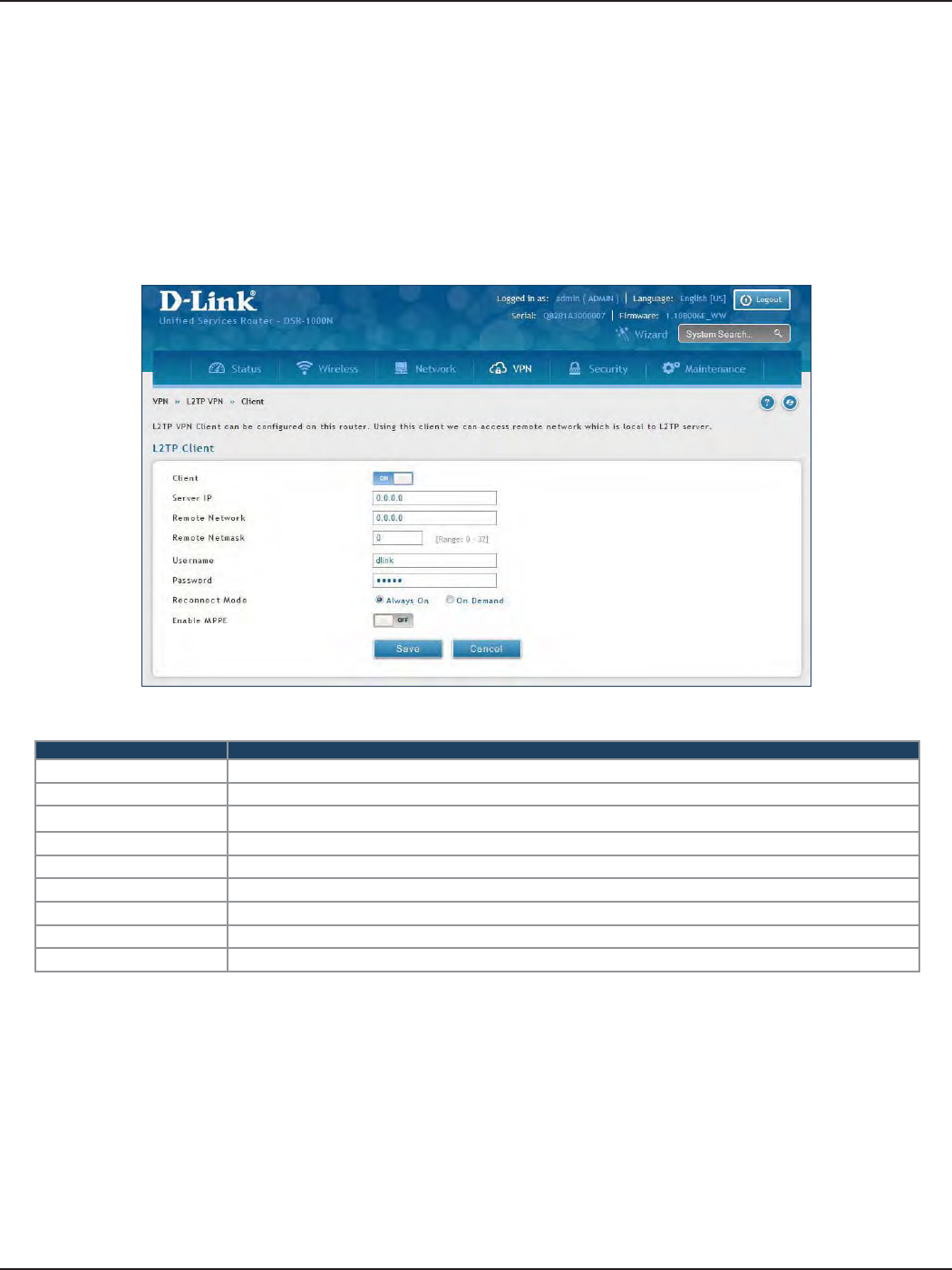
D-Link DSR-Series User Manual 106
Section 7 - VPN
Client
Field Description
Client Toggle to ON to enable L2TP client.
Server IP Enter the IP address of the L2TP server you want to connect to.
Remote Network Enter the remote network address. This address is local for the L2TP Server.
Remote Netmask Enter the remote network subnet mask.
Username Enter your L2TP user name.
Password Enter your L2TP password.
Reconnect Mode Select Always On or On Demand.
MPPE Encryption Toggle to ON to enable Microsoft Point-to-Point Encryption (MPPE).
Save Click Save to save and activate your settings.
L2TP VPN Client can be congured on this router. Using this client we can access remote network which is local to
L2TP server. Once client is enabled, the user can access Status > Active VPNs page and establish L2TP VPN tunnel
clicking Connect.
To congure the router as a L2TP VPN client:
1. Click VPN > L2TP VPN > Client tab.
2. Toggle Client to ON and complete the elds in the table below.
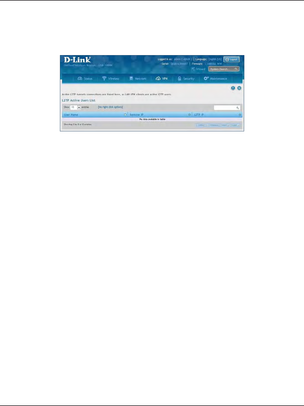
D-Link DSR-Series User Manual 107
Section 7 - VPN
L2TP Active Users List
A list of L2TP connections will be displayed on this page. Right-click the connection to connect and disconnect.
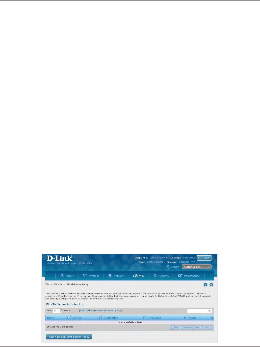
D-Link DSR-Series User Manual 108
Section 7 - VPN
SSL VPN
SSL VPN Policies can be created on a Global, Group, or User level. User level policies take precedence over Group
level policies and Group level policies take precedence over Global policies. These policies can be applied to a
specic network resource, IP address, or IP ranges on the LAN, or to dierent SSL VPN services supported by the
router. The List of Available Policies can be ltered based on whether it applies to a user, group, or all users (global).
To add a SSL VPN policy, you must rst assign it to a user, group, or make it global (i.e., applicable to all SSL VPN
users). If the policy is for a group, the available congured groups are shown in a drop-down menu and one
must be selected. Similarly, for a user-dened policy, a SSL VPN user must be chosen from the available list of
congured users.
The next step is to dene the policy details. The policy name is a unique identier for this rule. The policy can
be assigned to a specic Network Resource (details follow in the subsequent section), IP address, IP network,
or all devices on the LAN of the router. Based on the selection of one of these four options, the appropriate
conguration elds are required (i.e., choosing the network resources from a list of dened resources, or dening
the IP addresses). For applying the policy to addresses the port range/port number can be dened.
The nal steps require the policy permission to be set to either permit or deny access to the selected addresses
or network resources. As well the policy can be specied for one or all of the supported SSL VPN services (i.e. VPN
tunnel).
Once dened, the policy goes into eect immediately. The policy name, SSL service it applies to, destination
(network resource or IP addresses), and permission (deny/permit) is outlined in a list of congured policies for
the router.
Note: You must enable Remote Management. Refer to “Remote Management” on page 172.
To create a new SSL VPN policy:
1. Make sure you have enabled remote management and have created user(s) and group(s) to assign to
this policy.
2. Click VPN > SSL VPN > SSL VPN Server Policy.
3. Click Add New SSL VPN Server Policy.
Server Policies
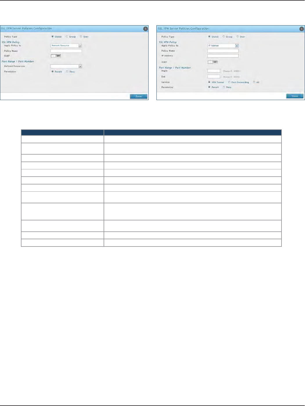
D-Link DSR-Series User Manual 109
Section 7 - VPN
4. Complete the elds from the table below and click Save.
Field Description
Policy Type Select Global, Group, or User.
Available Groups/Users If you selected Group, select a group from the drop-down menu. If you selected User,
select a user from the drop-down menu.
Apply Policy To Select Network Resource, IP Address, IP Network, or All Addresses.
Policy Name Enter a unique name for this policy.
IP Address If you selected IP Address or IP Network, enter the IP address.
Mask Length If you selected IP Network, enter the mask length (0-32).
ICMP Toggle to ON to include ICMP trac.
Begin/End Enter a port range or leave blank to include all TCP and UDP ports. These elds are not
available when selecting Network Resource.
Dened Resources
If you selected Network Resource, select the resource for the Dened Resource drop-
down menu. If you have not created a resource, refer to “Resources” on page 112 to create
a dened resource.
Service Select either VPN Tunnel, Port Forwarding, or All. This eld is not available when
selecting Network Resource.
Permission Select either Permit or Deny.
Save Click to save your settings.
Network Resource IP Address
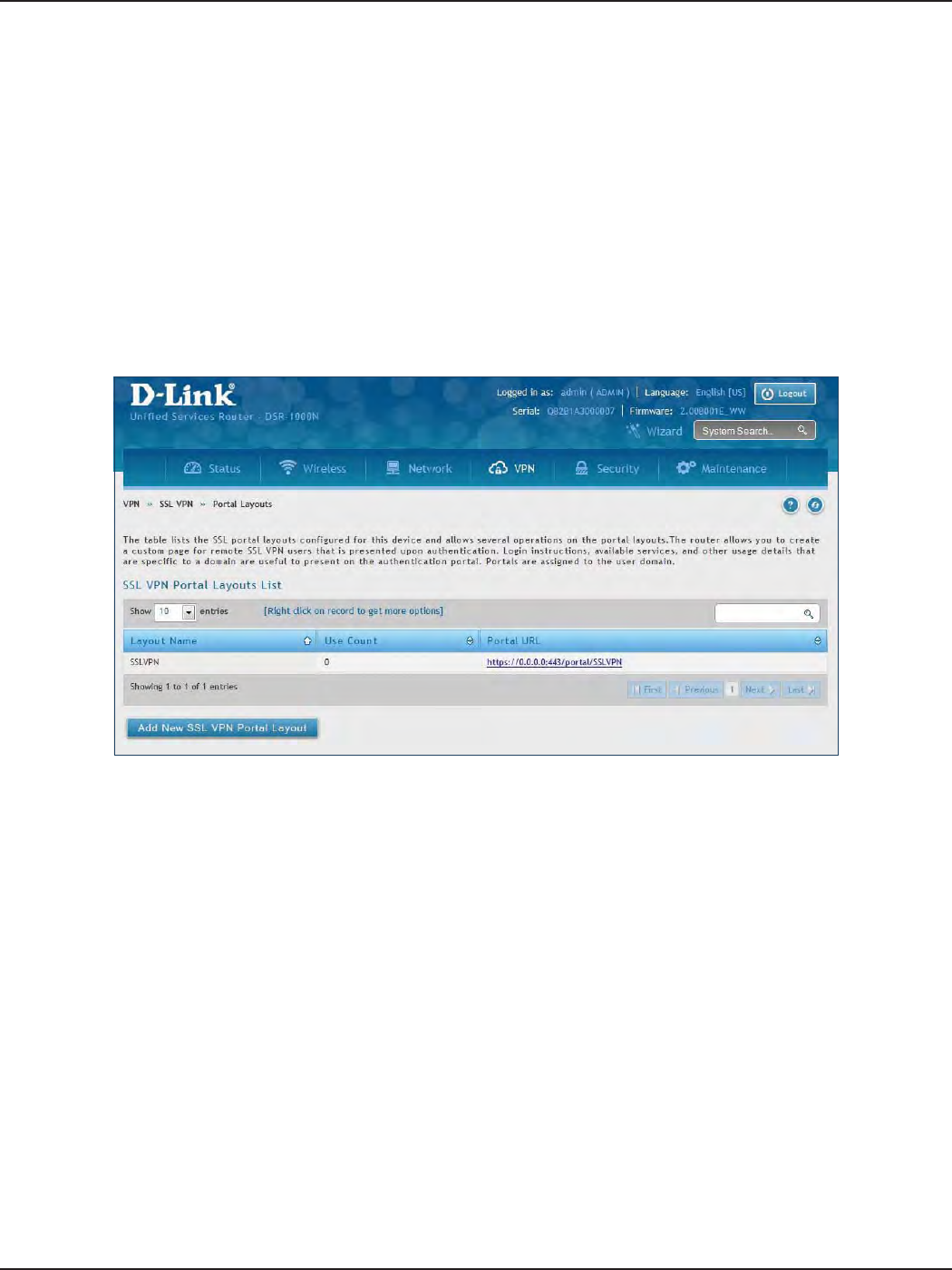
D-Link DSR-Series User Manual 110
Section 7 - VPN
Portal Layouts
Path: VPN > SSL VPN > Portal Layouts
You may create a custom page for remote VPN users that is viewed during authentication. You may include
login instructions, services, and other details. Note that the default portal LAN IP address is https://192.168.10.1/
scgi-bin/userPortal/portal. This is the same page that opens when the “User Portal” link is clicked on the SSL VPN
menu of the router web UI.
To create a new portal layout:
1. Click VPN > SSL VPN > Portal Layouts.
2. Click Add New SSL VPN Portal Layout.
Note: You may right-click a layout from the list and edit or delete a layout.
3. Complete the elds from the table on the next page and click Save.
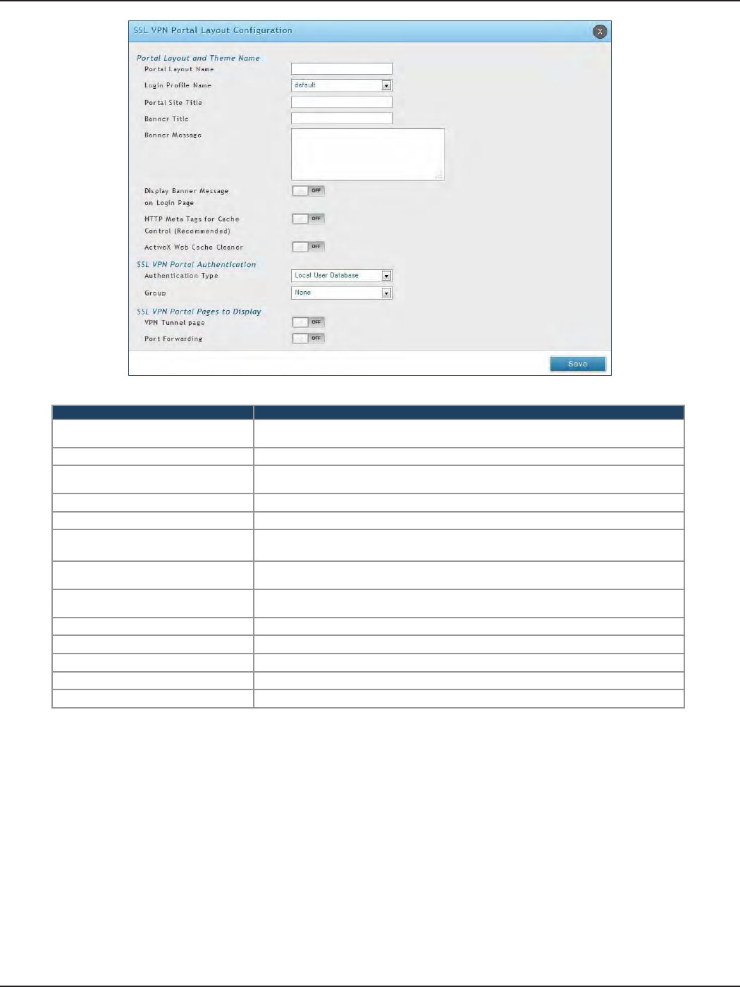
D-Link DSR-Series User Manual 111
Section 7 - VPN
Field Description
Portal Layout Name Enter a name for this portal. This name will be used as part of the path for the SSL portal
URL. Only alphanumeric characters are allowed for this eld.
Login Prole View Select a login prole from the drop-down menu.
Portal Site Title Enter the portal web browser window title that appears when the client accesses this
portal. This eld is optional.
Banner Title The banner title that is displayed to SSL VPN clients prior to login. This eld is optional.
Banner Message Enter a message you want to display.
Display Banner Message on Login
Page
Toggle to ON to display the banner title and message or OFF to hide the banner title
and message.
HTTP Meta Tags for Cache Control Toggle to ON or OFF. This security feature prevents expired web pages and data from
being stored in the client‘s web browser cache. It is recommended to toggle to ON.
Active X Web Cache Cleaner Toggle to ON or O. An ActiveX cache control web cleaner can be pushed from the
gateway to the client browser whenever users login to this SSL VPN portal.
Authentication Type Select the type of authentication from the drop-down menu.
Group Select what group to include from the drop-down menu.
VPN Tunnel Page Toggle to ON to allow remote users to view this page.
Port Forwarding Toggle to ON to allow remote users to view this page.
Save Click to save your settings.
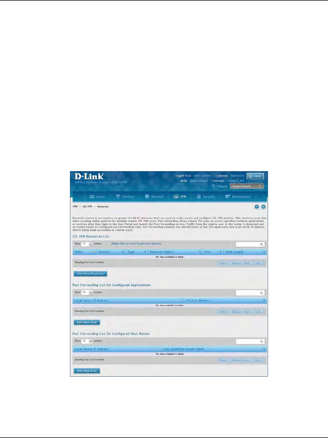
D-Link DSR-Series User Manual 112
Section 7 - VPN
Resources
Path: VPN > SSL VPN > Resources
Network resources are services or groups of LAN IP addresses that are used to easily create and congure SSL
VPN policies. This shortcut saves time when creating similar policies for multiple remote SSL VPN users.
Adding a Network Resource involves creating a unique name to identify the resource and assigning it to one or
all of the supported SSL services. Once this is done, editing one of the created network resources allows you to
congure the object type (either IP address or IP range) associated with the service. The Network Address, Mask
Length, and Port Range/Port Number can all be dened for this resource as required.
3. Complete the elds from the table on the next page and click Save.
Add New Resource
To add a new resource:
1. Click VPN > SSL VPN > Resources.
2. Click Add New Resource.
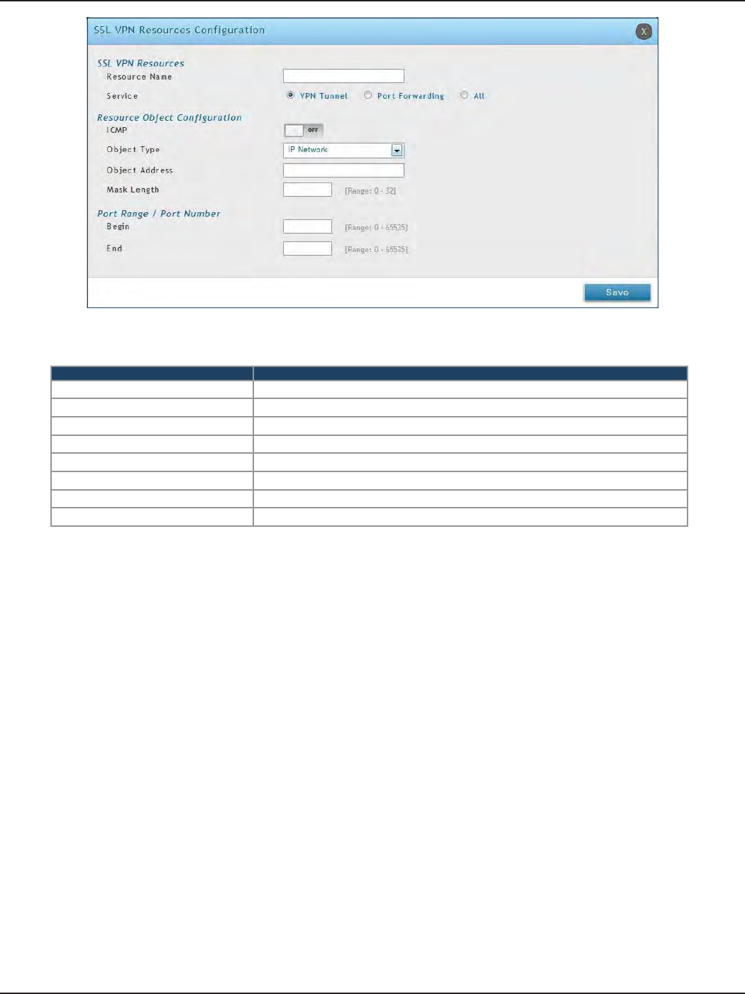
D-Link DSR-Series User Manual 113
Section 7 - VPN
Field Description
Resource Name Enter a unique name for this resource.
Service Select VPN Tunnel, Port Forwarding, or All.
ICMP Toggle to ON to include ICMP trac.
Object Type Select Single IP Address or IP Network.
Object Address Enter the IP address.
Mask Length If you selected IP Network, enter the mask length (0-32).
Begin/End Enter a port range for the object.
Save Click to save your settings.
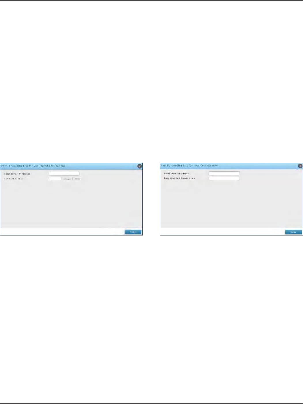
D-Link DSR-Series User Manual 114
Section 7 - VPN
Port Forwarding
To add a port forwarding rule:
1. Click VPN > SSL VPN > Resources.
2. Click Add New Rule under either Port Forwarding List for Congured Applications (TCP Port) or under
Port Forwarding List for Congured Host Names (FQDN).
3. Enter the IP address of the local server.
4. Next enter either the TCP port number or the domain name (FQDN).
5. Click Save.
Port forwarding allows remote SSL users to access specied network applications or services after they login to
the User Portal and launch the Port Forwarding service. Trac from the remote user to the router is detected and
re-routed based on congured port forwarding rules.
Internal host servers or TCP applications must be specied as being made accessible to remote users. Allowing
access to a LAN server requires entering the local server IP address and TCP port number of the application to be
tunnelled.
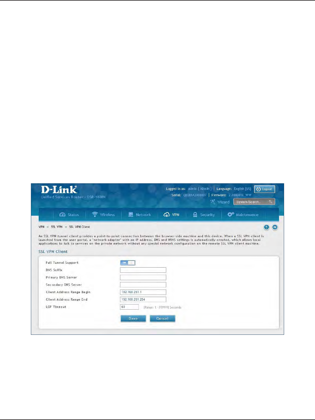
D-Link DSR-Series User Manual 115
Section 7 - VPN
Client
To congure client mode:
1. Click VPN > SSL VPN > SSL VPN Client.
Path: VPN > SSL VPN > SSL VPN Client
An SSL VPN tunnel client provides a point-to-point connection between the browser-side machine and this
router. When a SSL VPN client is launched from the user portal, a "network adapter" with an IP address from the
corporate subnet, DNS and WINS settings is automatically created. This allows local applications to access services
on the private network without any special network conguration on the remote SSL VPN client machine.
It is important to ensure that the virtual (PPP) interface address of the VPN tunnel client does not conict with
physical devices on the LAN. The IP address range for the SSL VPN virtual network adapter should be either in a
dierent subnet or non-overlapping range as the corporate LAN.
The router allows full tunnel and split tunnel support. Full tunnel mode just sends all trac from the client
across the VPN tunnel to the router. Split tunnel mode only sends trac to the private LAN based on pre-
specied client routes. These client routes give the SSL client access to specic private networks, thereby
allowing access control over specic LAN services.
2. Toggle Full Tunnel Support to ON to support full tunnel or OFF to enable split tunnel.
3. Enter a DNS sux to assign to this client (optional).
3. Enter a primary and secondary DNS server addresses (optional).
4. Enter the range of IP addresses clients will be assigned (DHCP).
5. Next to LCP Timeout, set the value for LCP echo interval (in seconds).
6. Click Save.
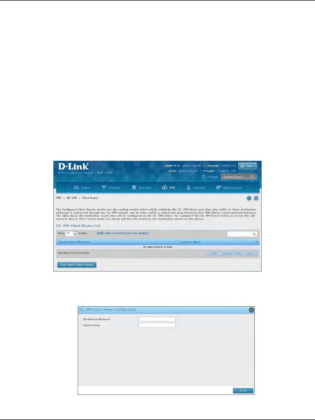
D-Link DSR-Series User Manual 116
Section 7 - VPN
Client Routes
Path: VPN > SSL VPN > SSL VPN Client
If the SSL VPN client is assigned an IP address in a dierent subnet than the corporate network, a client route
must be added to allow access to the private LAN through the VPN tunnel. As well a static route on the private
LAN‘s rewall (typically this router) is needed to forward private trac through the VPN Firewall to the remote
SSL VPN client.
When split tunnel mode is enabled, the user is required to congure routes for VPN tunnel clients:
• Destination network: The network address of the LAN or the subnet information of the
destination network from the VPN tunnel clients‘ perspective is set here.
• Subnet mask: The subnet information of the destination network is set here.
To congure a client route:
1. Click VPN > SSL VPN > Client Routes.
2. Click Add New Client Route.
3. Enter the destination network and subnet mask.
4. Click Save.
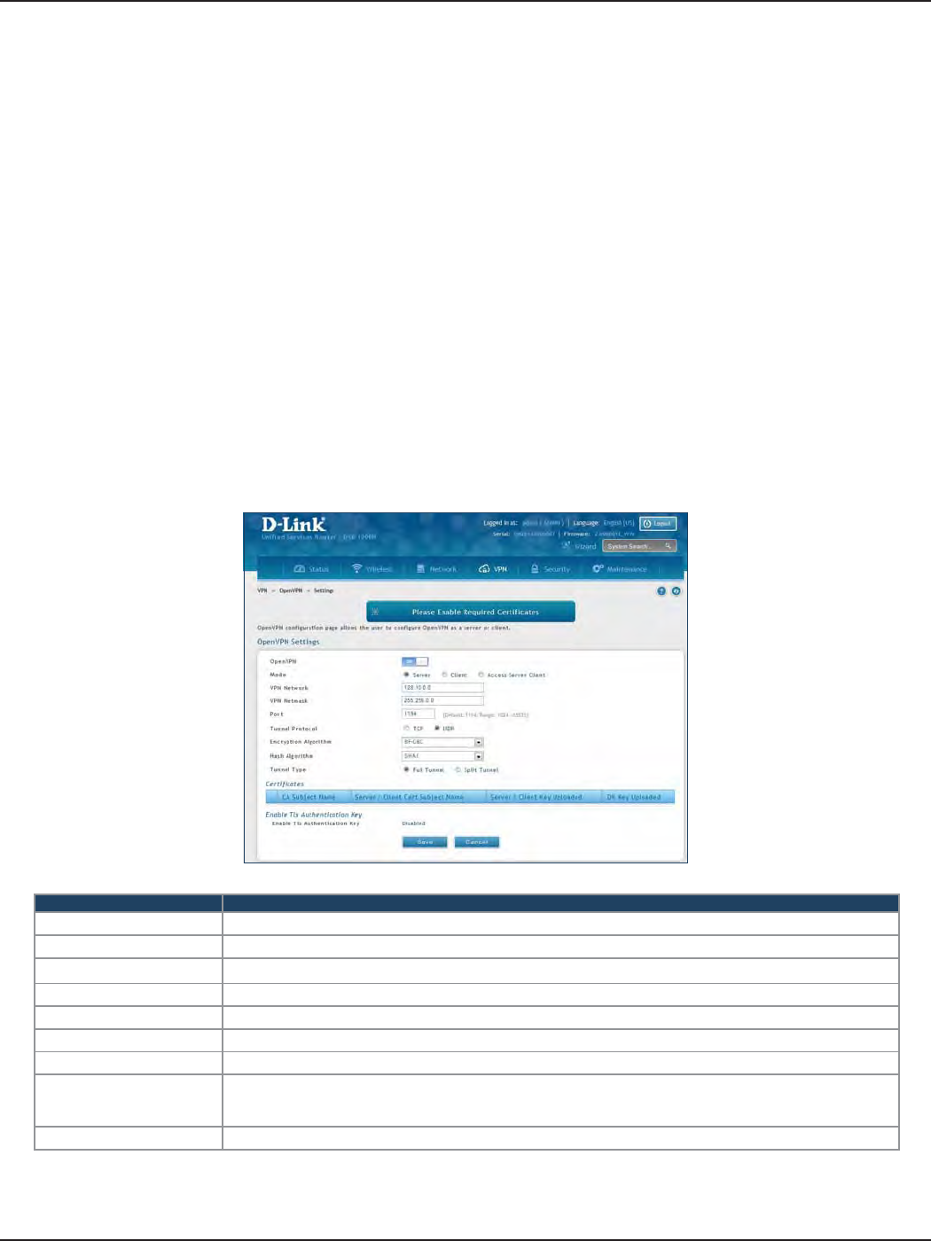
D-Link DSR-Series User Manual 117
Section 7 - VPN
Open VPN
VPN > OpenVPN > Settings
OpenVPN allows peers to authenticate each other using a pre-shared secret key, certicates, or username/
password. When used in a multiclient-server conguration, it allows the server to release an authentication
certicate for every client, using signature and Certicate authority. An OpenVPN can be established through
this router.
You can select server mode, client mode, or access server client mode. In access server client mode, the user has
to download the auto login prole from the OpenVPN Access Server and upload the same to connect.
Server
Settings
Field Description
Mode Select Server.
VPN Network Enter the IP network for the VPN.
VPN Netmask Enter the netmask.
Port Enter what port to use. The default port is 1194.
Tunnel Protocol Select either TCP or UDP.
Encryption Algorithm Select the encryption algorithm from the drop-down menu.
Hash Algorithm Select the hash algorithm from the drop-down menu.
Tunnel Type
Select either Full Tunnel or Split Tunnel. Full Tunnel mode just sends all trac from the client across the
VPN tunnel to the router. Split Tunnel mode only sends trac to the private LAN based on pre-specied
client routes. If you select Split Tunnel, refer to “Local Networks” on page 120 to create local networks.
Save Click Save to save and activate your settings.
To congure the router as an OpenVPN Server:
1. Click VPN > OpenVPN > Settings.
2. Toggle OpenVPN to ON and complete the elds in the table below.
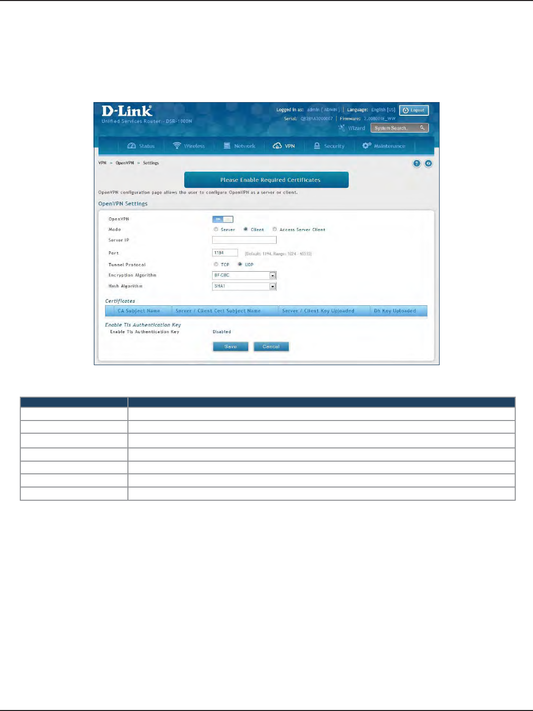
D-Link DSR-Series User Manual 118
Section 7 - VPN
Client
Field Description
Mode Select Client.
Server IP Enter the IP address of the OpenVPN server.
Port Enter what port to use. The default port is 1194.
Tunnel Protocol Select either TCP or UDP.
Encryption Algorithm Select the encryption algorithm from the drop-down menu.
Hash Algorithm Select the hash algorithm from the drop-down menu.
Save Click Save to save and activate your settings.
To congure the router as an OpenVPN client:
1. Click VPN > OpenVPN > Settings.
2. Toggle OpenVPN to ON and complete the elds in the table below.
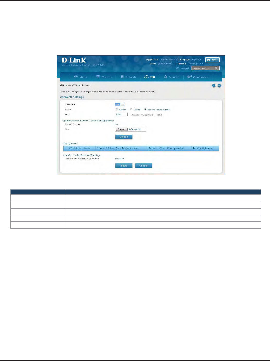
D-Link DSR-Series User Manual 119
Section 7 - VPN
Access Server Client
Field Description
Mode Select Access Server Client.
Port Enter what port to use. The default port is 1194.
Upload Status Displays if a conguration le has been uploaded.
File Click Browse and locate the conguration le. Click Open and then click Upload.
Save Click Save to save and activate your settings.
To congure the router as an OpenVPN access server client:
1. Click VPN > OpenVPN > Settings.
2. Toggle OpenVPN to ON and complete the elds in the table below.
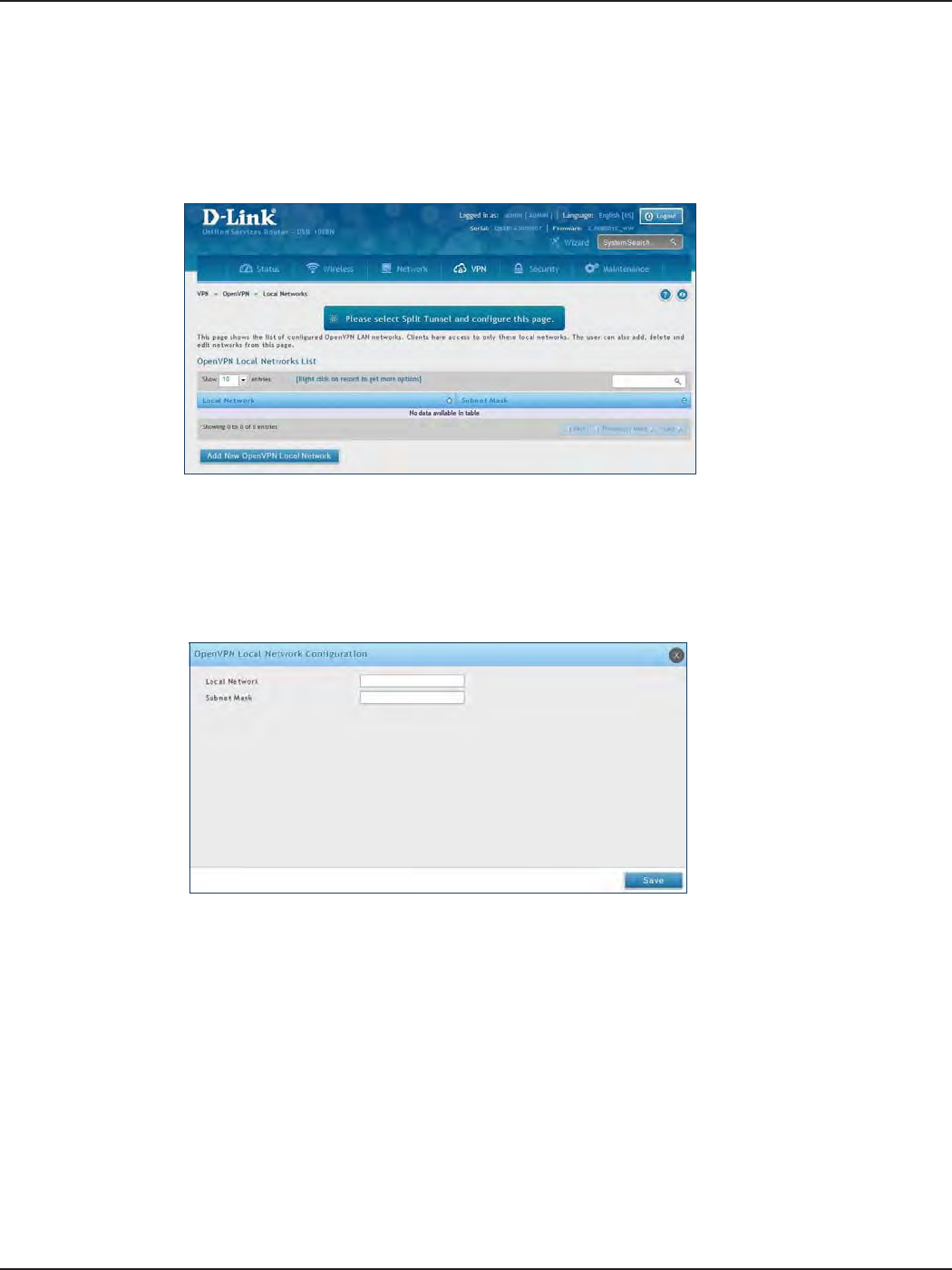
D-Link DSR-Series User Manual 120
Section 7 - VPN
Local Networks
If you selected Split Tunnel (from OpenVPN Server), you can create a local network by following the steps below:
1. Click VPN > OpenVPN > Local Networks.
2. Click Add New OpenVPN Local Network.
3. Enter a local IP network.
4. Enter the subnet mask.
5. Click Save.
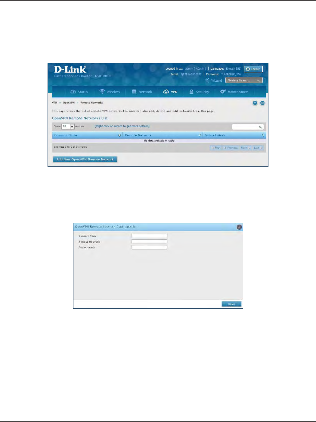
D-Link DSR-Series User Manual 121
Section 7 - VPN
Remote Networks
To create remote networks:
1. Click VPN > OpenVPN > Remote Networks.
2. Click Add New OpenVPN Remote Network.
3. Enter a name of the remote network.
4. Enter a local IP network.
5. Enter the subnet mask.
6. Click Save.
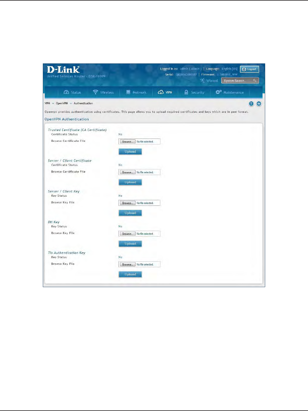
D-Link DSR-Series User Manual 122
Section 7 - VPN
Authentication
This page will allow you to upload certicates and keys. Click Browse and select the le you want to upload. Click
Open and then click Upload.
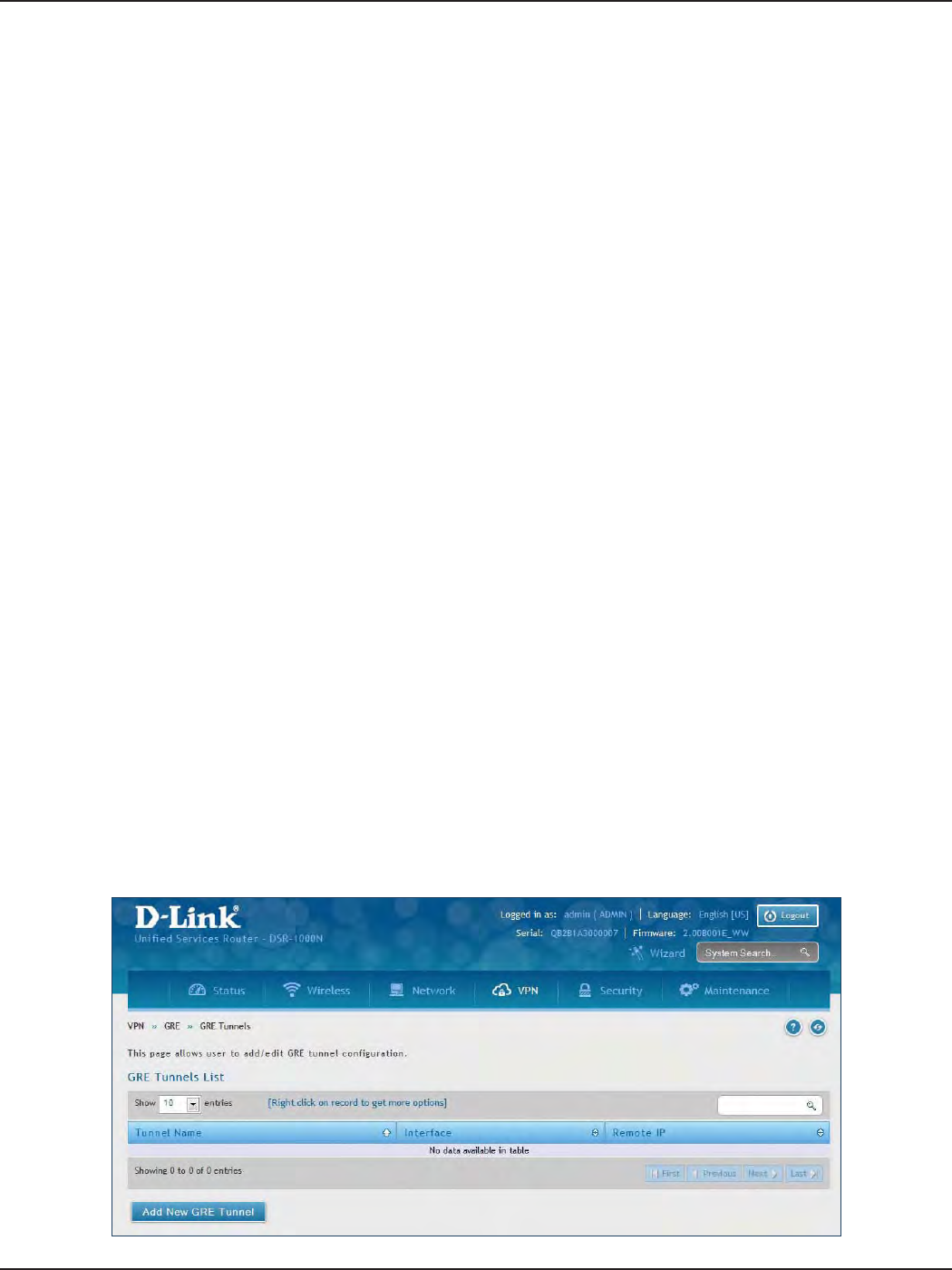
D-Link DSR-Series User Manual 123
Section 7 - VPN
GRE
VPN > VPN Settings > GRE
GRE tunnels allow for broadcast trac on the LAN of the router to be passed over the internet and received by
remote LAN hosts. This is primarily useful in the D-Link Discovery Protocol (DDP) application where broadcast
trac from one LAN host is to be received by all LAN hosts in the local subnets of the GRE endpoints.
Note the following limits for the number of supported GRE tunnels per product:
• DSR-150/150N: 5
• DSR-250/250N: 10
• DSR-500/500N: 15
• DSR-1000/1000N: 20
There are two simple steps involved in establishing a GRE tunnel on the router:
1. Create a GRE tunnel from the GUI
2. Setup a static route for the remote local networks using the GRE tunnel
When creating the GRE tunnel, the IP Address should be a unique address that identies that GRE tunnel endpoint.
It will be referenced in the other router’s static route as the Gateway IP address. The Remote End Address in the
GRE tunnel conguration page is the WAN IP address of the other endpoint router.
Once the tunnel is established, a static route on the router can be made using the interface set to the congured
GRE tunnel name. The destination IP address of the static route is the remote LAN subnet, and the route’s gateway
IP address will be the GRE tunnel IP of the terminating router (the same router that manages the remote LAN
subnet). Once these two steps are completed, all DDP broadcast trac can ow between remote LAN subnets
via the GRE Tunnel.
To create a GRE tunnel:
1. Click VPN > GRE > GRE Tunnels.
2. Click Add New GRE Tunnel.
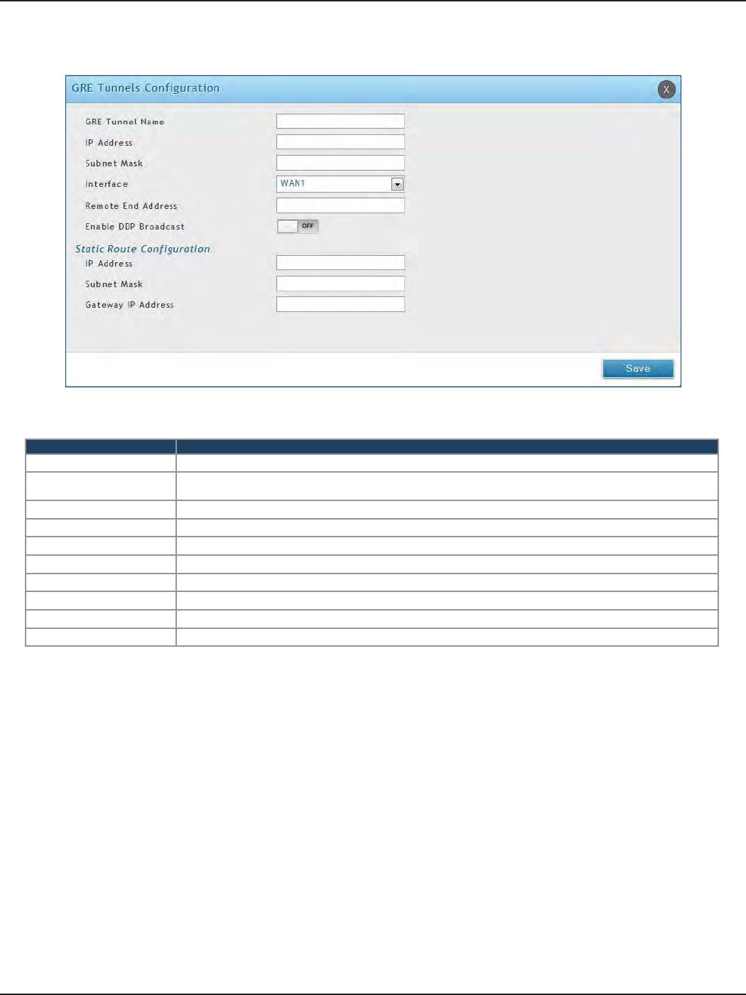
D-Link DSR-Series User Manual 124
Section 7 - VPN
3. Complete the elds in the table below and then click Save.
Field Description
GRE Tunnel Name Enter a name for the tunnel.
IP Address Enter the IP address of this endpoint. It will be referenced in the other router’s static route as the Gateway
IP address.
Subnet Mask Enter the subnet mask.
Interface Select the interface to create this tunnel with from the drop-down menu.
Remote End Address Enter the WAN IP address of the endpoint router.
Enable DDP Broadcast Toggle to ON to enable DDP broadcasting.
IP Address Enter the destination IP address of the static route from the remote LAN subnet.
Subnet Mask Enter the subnet mask.
Gateway IP Address Enter the IP address of the termination router.
Save Click Save to save and activate your settings.
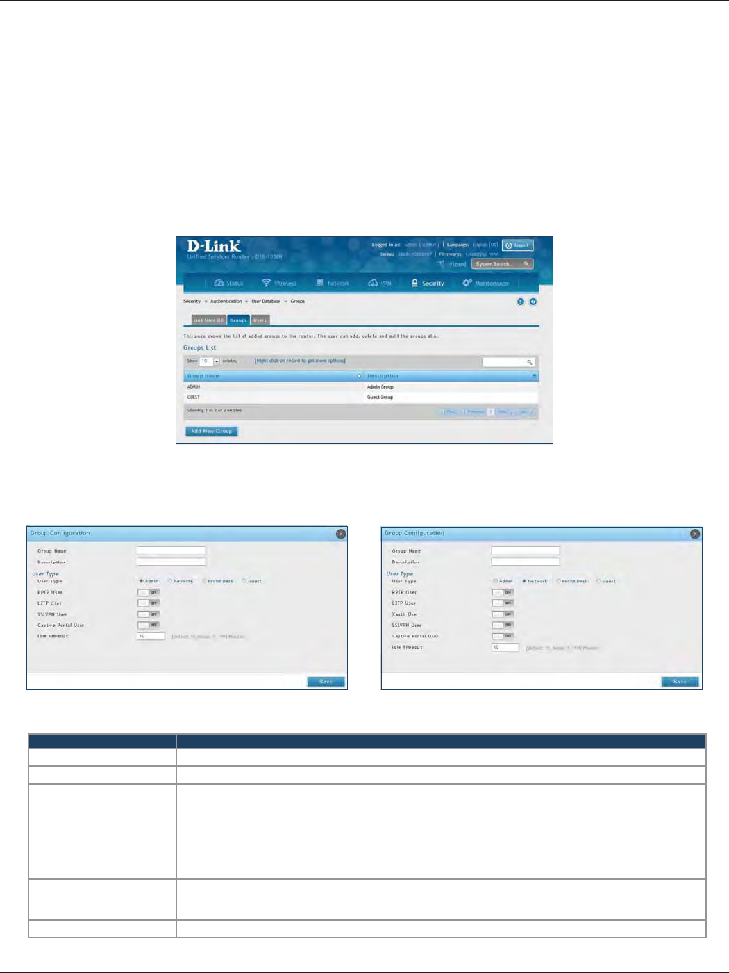
D-Link DSR-Series User Manual 125
Section 8 - Security
Field Description
Group Name Enter a name for the group.
Description Enter a description for the group.
User Type
Select the user type:
• Admin - Grants all users in this group super-user privileges. By default, there is one admin user.
• Network - Grants the next level of privileges.
• Front Desk - Grants permissions to create temporary users who can Internet/network access (Hotspot).
• Guest - Guest users will only have read access.
Network and Admin users can toggle ON PPTP, L2TP, Xauth (Network only), SSLVPN, and Captive Portal.
Idle Timeout
Enter the number of minutes of inactivity that must occur before the users in this user group are logged out
of their web management session automatically. Entering an Idle Timeout value of 0 (zero) means never log
out.
Save Click Save at the bottom to save and activate your settings.
Groups
Path: Security > Authentication > User Database > Groups
The group page allows creating, editing, and deleting groups. The groups are associated to set of user types.
To edit/delete an existing group, or add a new group:
1. Click Security > Authentication > User Database > Groups tab.
2. Right-click a group entry and select either Edit or Delete. To add a new group, click Add New Group.
3. Complete the elds in the table below and click Save.
Admin User Type Network User Type
Security
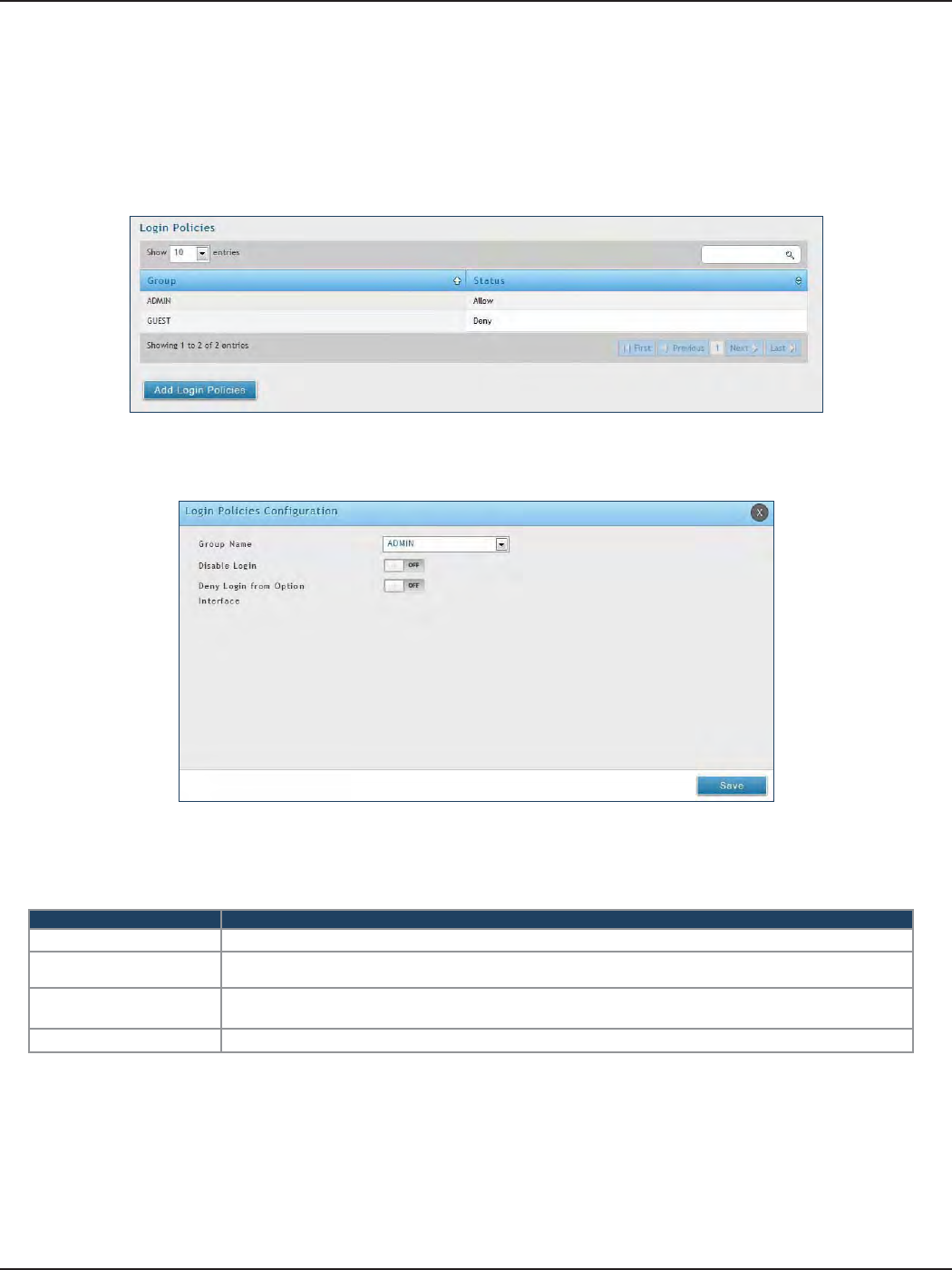
D-Link DSR-Series User Manual 126
Section 8 - Security
Login Policies
Path: Security > Authentication > Internal User Database > Groups
Using the following procedure, you can grant or deny a user group login access to the web management interface.
1. Click Security > Authentication > Internal User Database > Groups tab.
2. Click Add Login Policies.
3. Complete the elds from the table below and click Save.
Field Description
Group Name Select the group you want to congure.
Disable Login Toggle ON to deny login access to the web management interface for all users in this user group. Toggle OFF
will allow users to log in.
Deny Login from Option
Interface
Toggle ON to deny login access to the web management interface from the WAN2/DMZ Port for all users in
this user group. Toggle OFF will allow users.
Save Click Save at the bottom to save and activate your settings.
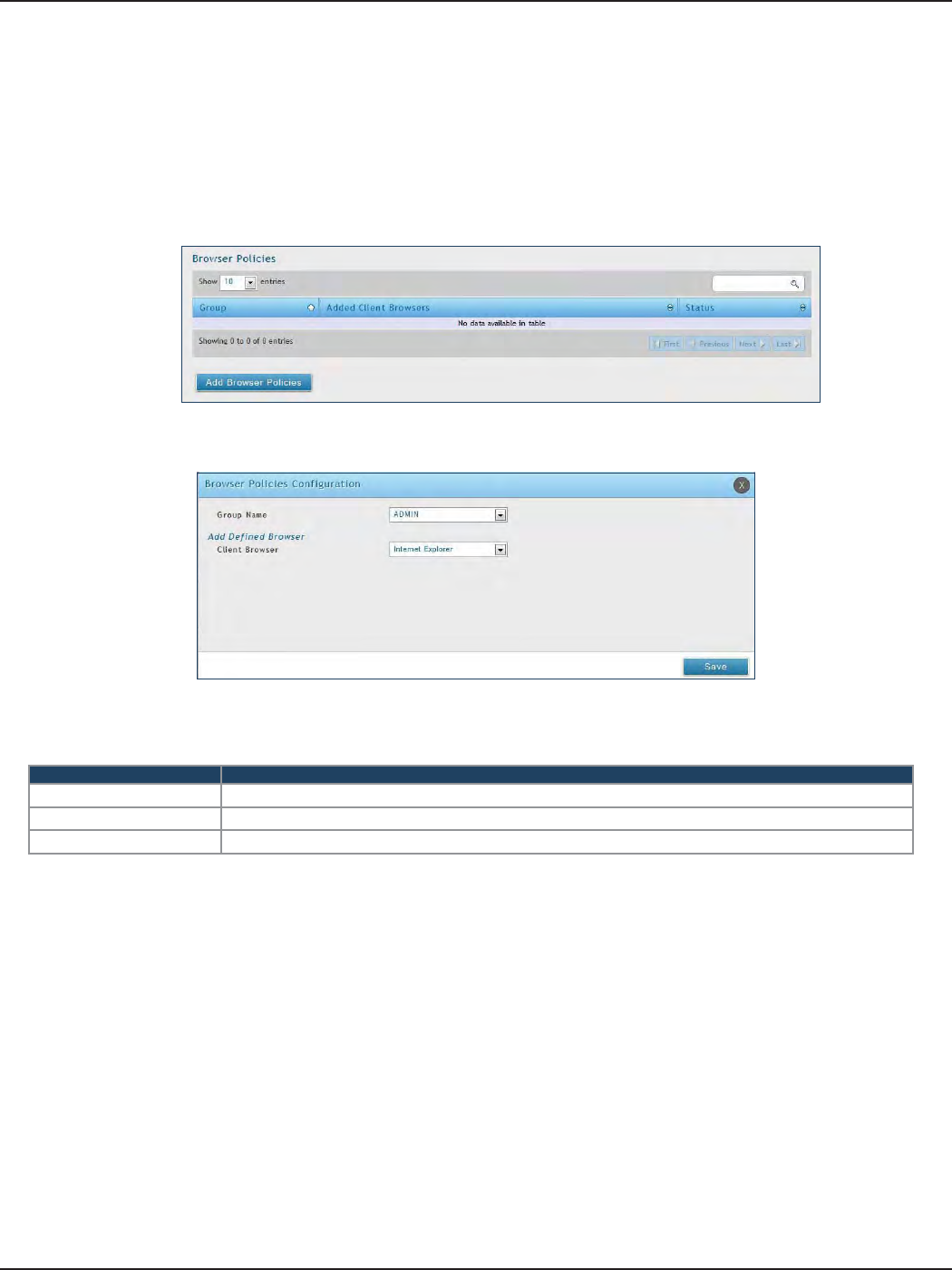
D-Link DSR-Series User Manual 127
Section 8 - Security
Path: Security > Authentication > Internal User Database > Groups
Use this feature to allow or deny users in a selected group from using a particular web browser to log in to the
router’s web management interface.
1. Click Security > Authentication > Internal User Database > Groups tab.
Browser Policies
2. Click Add Browser Policies.
3. Complete the elds from the table below and click Save.
Field Description
Group Name Select the group you want to congure from the drop-down menu.
Client Browser Select a web browser from the drop-down menu.
Save Click Save at the bottom to save and activate your settings.
4. Your policy will now be in the browser policies list. By default the status will be set to deny. If you
want to set the status to allow, right-click the policy and select Allow.
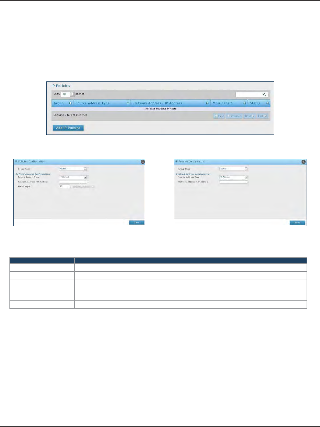
D-Link DSR-Series User Manual 128
Section 8 - Security
Path: Security > Authentication > Internal User Database > Groups
Use this feature to allow or deny users in a user group to log in to the router’s web management interface from
a particular network or IP address.
1. Click Security > Authentication > Internal User Database > Groups tab.
IP Policies
2. Click Add IP Policies.
3. Complete the elds from the table below and click Save.
Field Description
Group Name Select the group you want to congure from the drop-down menu.
Source Address Type Select either Network to specify a IP network or IP Address to specify a specic IP address.
Network Address/IP
Address Enter the network address or IP address.
Mask Length If you selected Network, enter the mask length.
Save Click Save at the bottom to save and activate your settings.
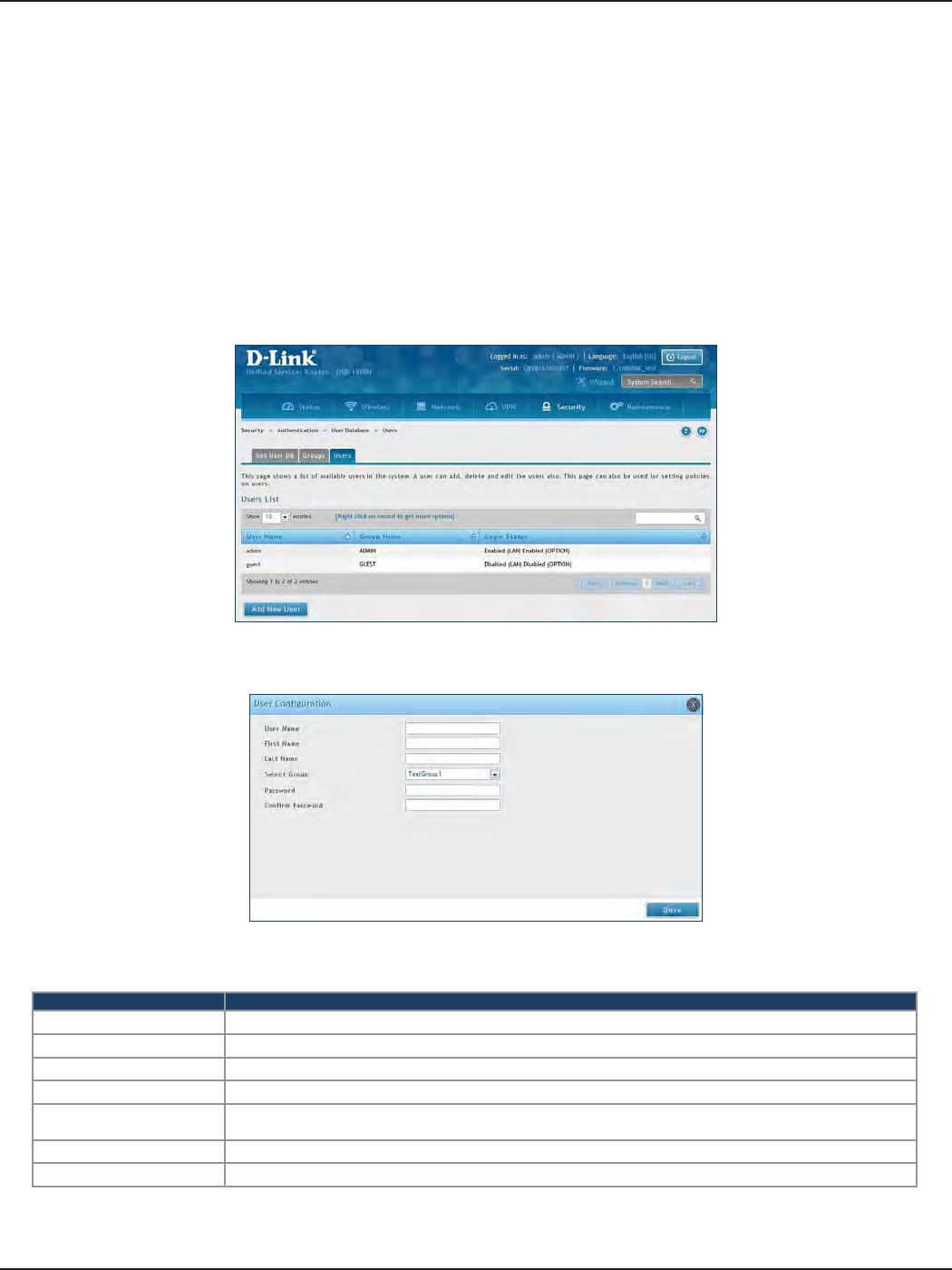
D-Link DSR-Series User Manual 129
Section 8 - Security
Users
Path: Security > Authentication > Internal User Database > Users
After you add user groups, you can add users to the user groups. Users can be added individually, or they can
be imported from a comma-separated-value (CSV) formatted le. After you add users, you can edit them when
changes are required or delete users when you no longer need them.
To edit/delete existing users, or add a new user:
1. Click Security > Authentication > Internal User Database > Users tab.
User Management
3. Complete the elds from the table below and click Save.
Field Description
User Name Enter the user name for this user. This name is a unique identier
First Name Enter the user’s rst name.
Last Name Enter the user’s last name.
Select Group Select the group you want to assign this user to from the drop-down menu.
Password Enter a case-sensitive login password that the user must specify at the login prompt to access the web
management interface. For security, each typed password character is masked with a dot (•).
Conrm Password Enter the password to conrm.
Save Click Save at the bottom to save and activate your settings.
2. Right-click a group entry and select either Edit or Delete. To add a new group, click Add New User.
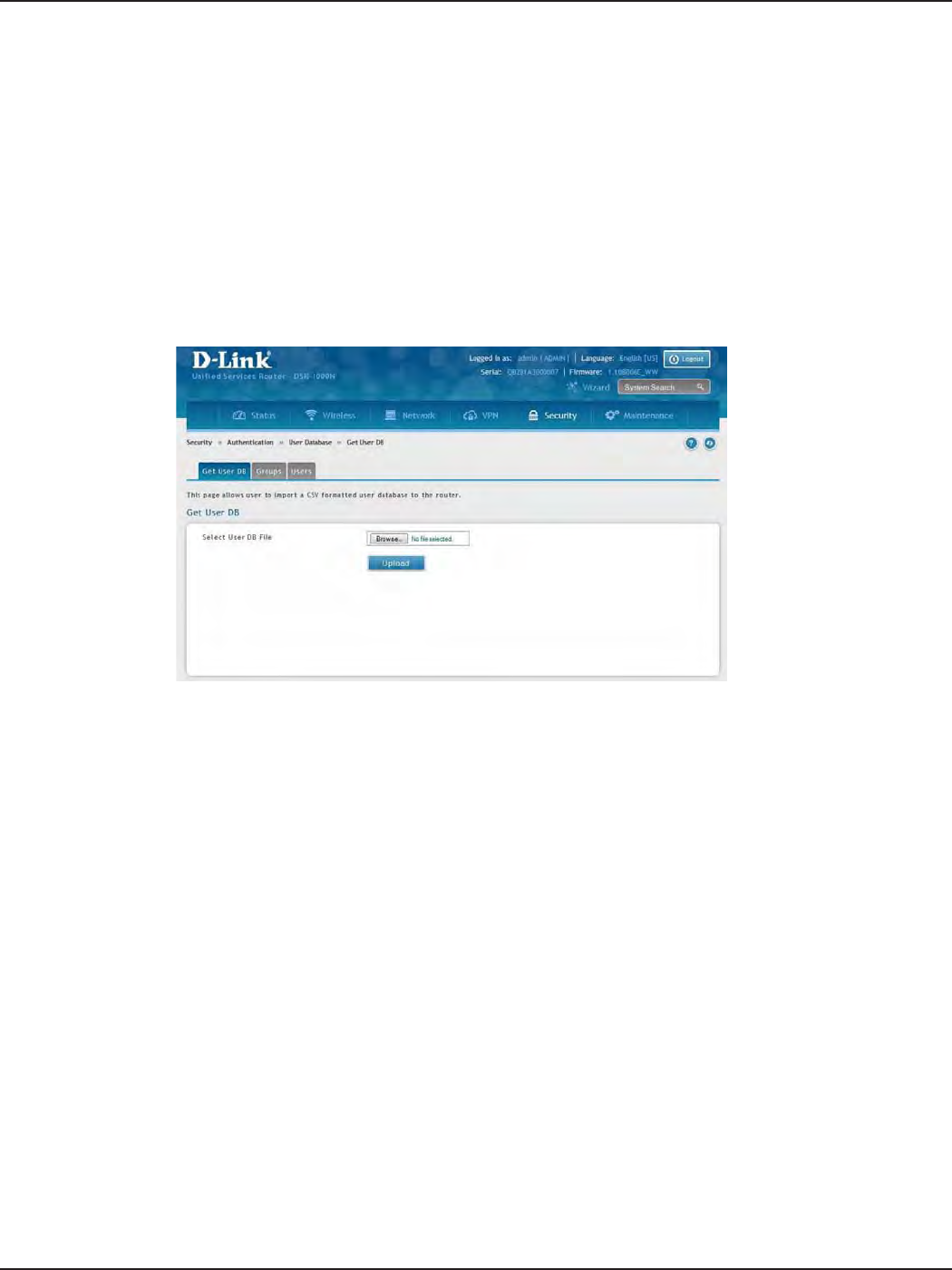
D-Link DSR-Series User Manual 130
Section 8 - Security
Path: Security > Authentication > Internal User Database > Get User DB
The DSR administrator can add users to the local built-in database directly via an appropriately-formatted comma
separated value (CSV) le. The advantage of this feature is to allow for a large number of users to be added to
the system with one operation, and the same le can be uploaded to multiple DSR devices as needed. Once
uploaded the specic users in the local user database can be modied via the GUI as needed.
To import a user database:
1. Click Security > Authentication > Internal User Database > Get User DB tab.
2. Click Browse and locate the le you want to upload. Select it and click Open.
3. Click Upload.
4. Once completed, go to Security > Authentication > User Database > Users and your imported users
will be displayed in the Users List.
5. From the list you can right-click the user to edit or delete.
Import User Database

D-Link DSR-Series User Manual 131
Section 8 - Security
The following parameters must be used to dene the User database CSV le.
1. Create an empty text le with a .csv extension.
2. Each line in the le corresponds to a single user entry. Every line should end with carriage return
equivalent of CRLF. Do not add comments or other text in this le.
3. Formatting rules:
a) All the elds must be enclosed within double quotes.
b) Consecutive elds are separated by commas.
c) There should be no leading or trailing spaces in a line.
d) There should be no spaces between elds.
Each line in the CSV user database le should follow the following format:
"UserName","FirstName","LastName","GroupName","MultiLogin","Password"
The above sample has elds that can assume the following values:
• Username (text eld): Name of the user and identier in the DSR’s database, and so it must
be unique in the local user database.
• FirstName (text eld): This is a user detail and need not be unique.
• LastName (text eld): This is a user detail and need not be unique.
• GroupName (text eld): The group that is associated with this user.
• MultiLogSup (Boolean value): With this enabled (“1”), then multiple users can share a single
username and password.
• Password (text eld): password to assign for this username
• The Group for a corresponding user (“GroupName” in the CSV) must be created via the GUI
in advance of the User Database CSV upload action.
• None of the above elds can be left empty or NULL in the User Database CSV.
Create a User Database (CSV File)
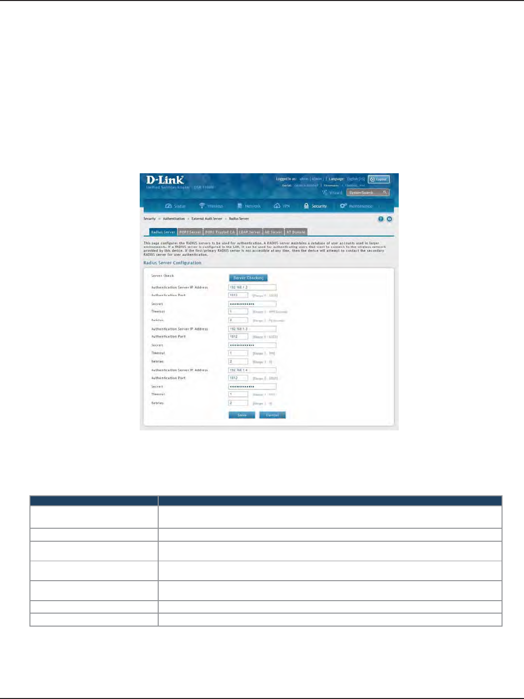
D-Link DSR-Series User Manual 132
Section 8 - Security
External Authentication Servers
Path: Security > Authentication > External Auth Server > RADIUS Server
A RADIUS server can be congured and accessible by the router to authenticate client connections.
To congure the router to connect to your RADIUS server:
1. Click Security > Authentication > External Auth Server > RADIUS Server tab.
RADIUS Server
Field Description
Authentication Server IP
Address Enter the IP address of your RADIUS server.
Authentication Port Enter the RADIUS authentication server port.
Secret Enter the secret key that allows the device to log into the congured RADIUS server. It must match
the secret on RADIUS server.
Timeout Set the amount of time in seconds that the router should wait for a response from the RADIUS
server.
Retries This determines the number of tries the controller will make to the RADIUS server before giving
up.
Save Click Save at the bottom to save and activate your settings.
Server Check Click to test the connection(s) to your RADIUS Server(s).
2. Complete the RADIUS server information from the table below and click Save. You can congure up to
three servers.
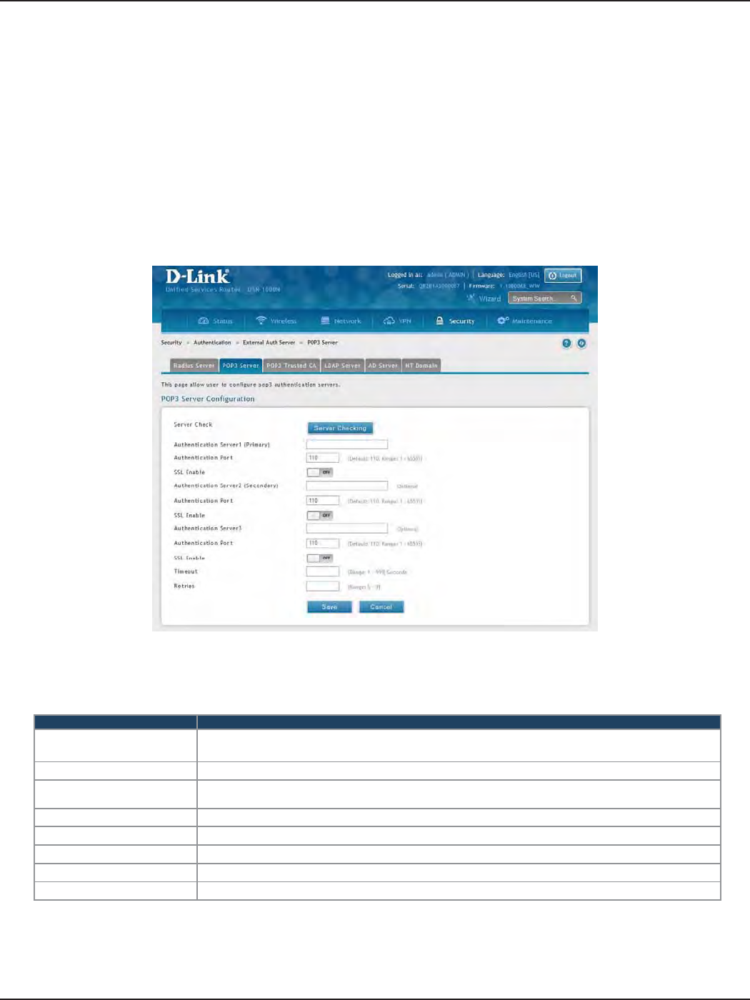
D-Link DSR-Series User Manual 133
Section 8 - Security
Path: Security > Authentication > External Auth Server > POP3 Server
POP3 is an application layer protocol most commonly used for e-mail over a TCP/IP connection. The authentication
server can be used with SSL encryption over port 995 to send encrypted trac to the POP3 server. The POP3
server’s certicate is veried by a user-uploaded CA certicate. If SSL encryption is not used, port 110 will be used
for the POP3 authentication trac.
To congure the router to connect to your POP3 server:
1. Click Security > Authentication > External Auth Server > POP3 Server tab.
POP3 Server
Field Description
Authentication Server IP
Address Enter the IP address of your POP3 server.
Authentication Port Enter the POP3 authentication server port.
SSL Enable Toggle to ON to enable SSL support for POP3. If this option is enabled, it is mandatory to select a
certicate authority for it.
CA File Certicate Authority to verify POP3 server’s certicate.
Timeout Set the amount of time in seconds that the router should wait for a response from the POP3 server.
Retries This determines the number of tries the controller will make to the POP3 server before giving up.
Save Click Save at the bottom to save and activate your settings.
Server Check Click to test the connection(s) to your POP3 Server(s).
2. Complete the POP3 server information from the table below and click Save. You can congure up to
three servers.
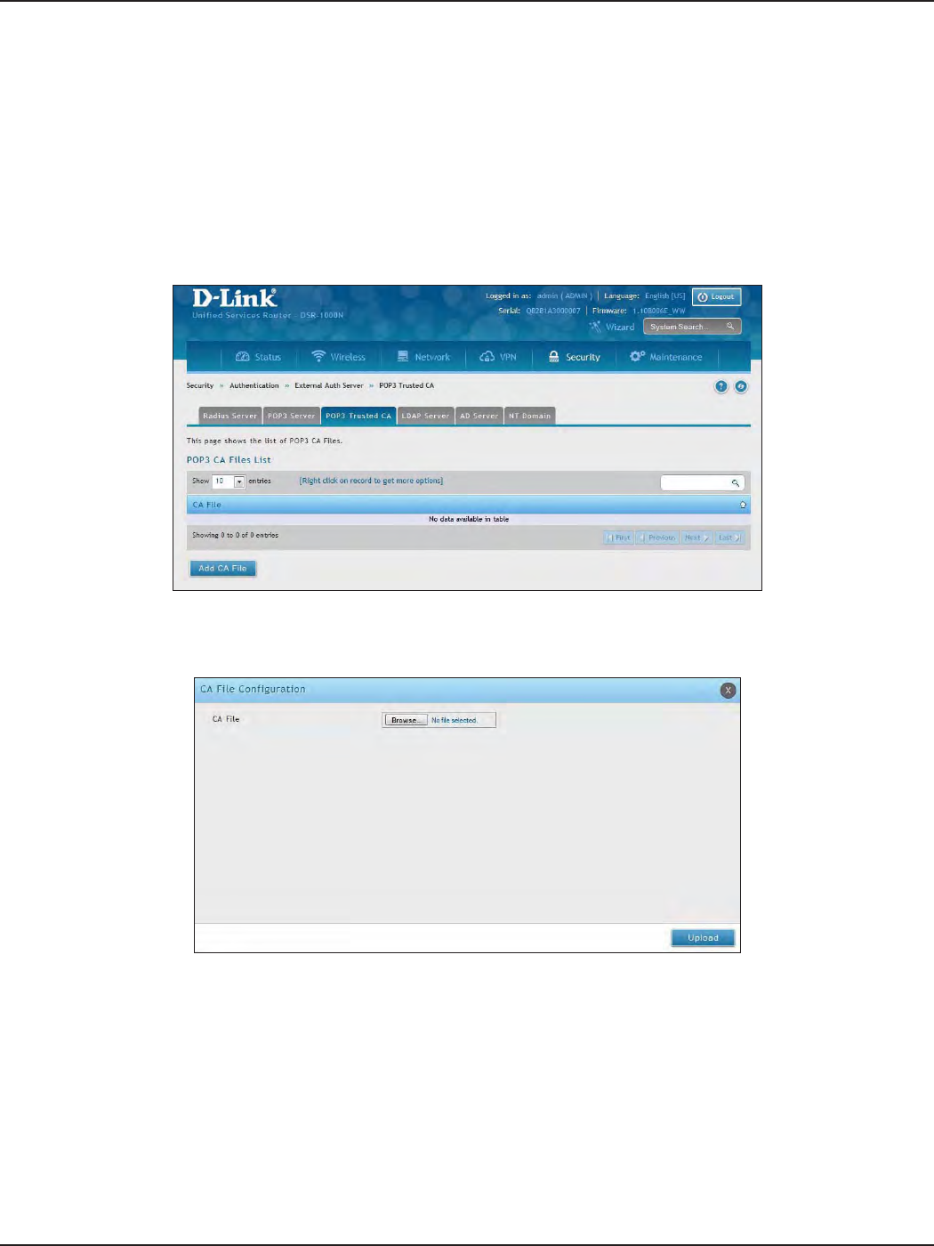
D-Link DSR-Series User Manual 134
Section 8 - Security
Path: Security > Authentication > External Auth Server > POP3 Trusted CA
A CA le is used as part of the POP3 negotiation to verify the congured authentication server identity. Each of
the three congured servers can have a unique CA used for authentication.
To congure:
1. Click Security > Authentication > External Auth Server > POP3 Trusted CA tab.
POP3 Trusted Server
2. Click Add CA File.
3. Click Browse and select a CA le. Click Open and then click Upload.
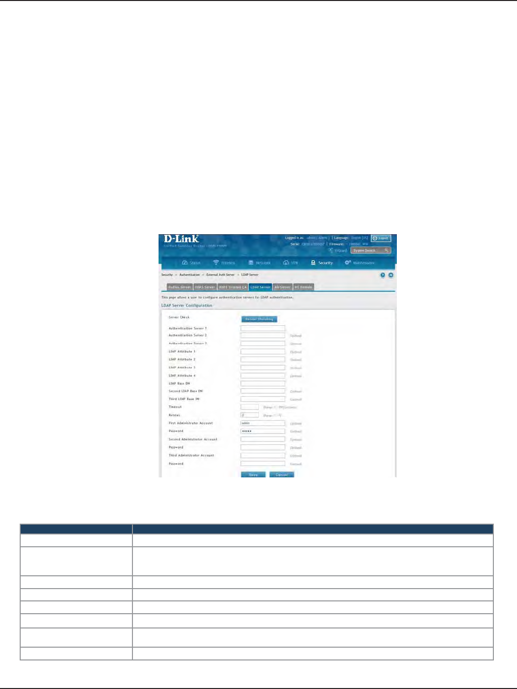
D-Link DSR-Series User Manual 135
Section 8 - Security
Path: Security > Authentication > External Auth Server > LDAP Server
The LDAP authentication method uses LDAP to exchange authentication credentials between the router and an
external server. The LDAP server maintains a large database of users in a directory structure, so users with the
same user name but belonging to dierent groups can be authenticated since the user information is stored in
a hierarchal manner. Also of note is that conguring a LDAP server on Windows or Linux servers is considerably
less complex than setting up NT Domain or Active Directory servers for user authentication.
The details congured on the controller will be passed for authenticating the router and its hosts. The LDAP
attributes, domain name (DN), and in some cases the administrator account & password are key elds in allowing
the LDAP server to authenticate the controller.
To congure the router to connect to your LDAP server:
1. Click Security > Authentication > External Auth Server > LDAP Server tab.
LDAP Server
Field Description
Authentication Server (1-3) Enter the IP address of your primary LDAP server.
LDAP Attribute (1-4)
These are attributes related to LDAP users congured in LDAP server. These may include attributes like
SAM account name, associated domain name etc. These can be used to distinguish between dierent
users having same user name.
LDAP Base DN Enter the base domain name.
Timeout Set the amount of time in seconds that the router should wait for a response from the LDAP server.
Retries This determines the number of tries the controller will make to the LDAP server before giving up.
Save Click Save at the bottom to save and activate your settings.
Administrator Account Enter the admin account information that will be used when LDAP authentication is required for PPTP/
L2TP connection.
Server Check Click to test the connection(s) to your LDAP Server(s).
2. Complete the LDAP server information from the table below and click Save. You can congure up to
three servers.
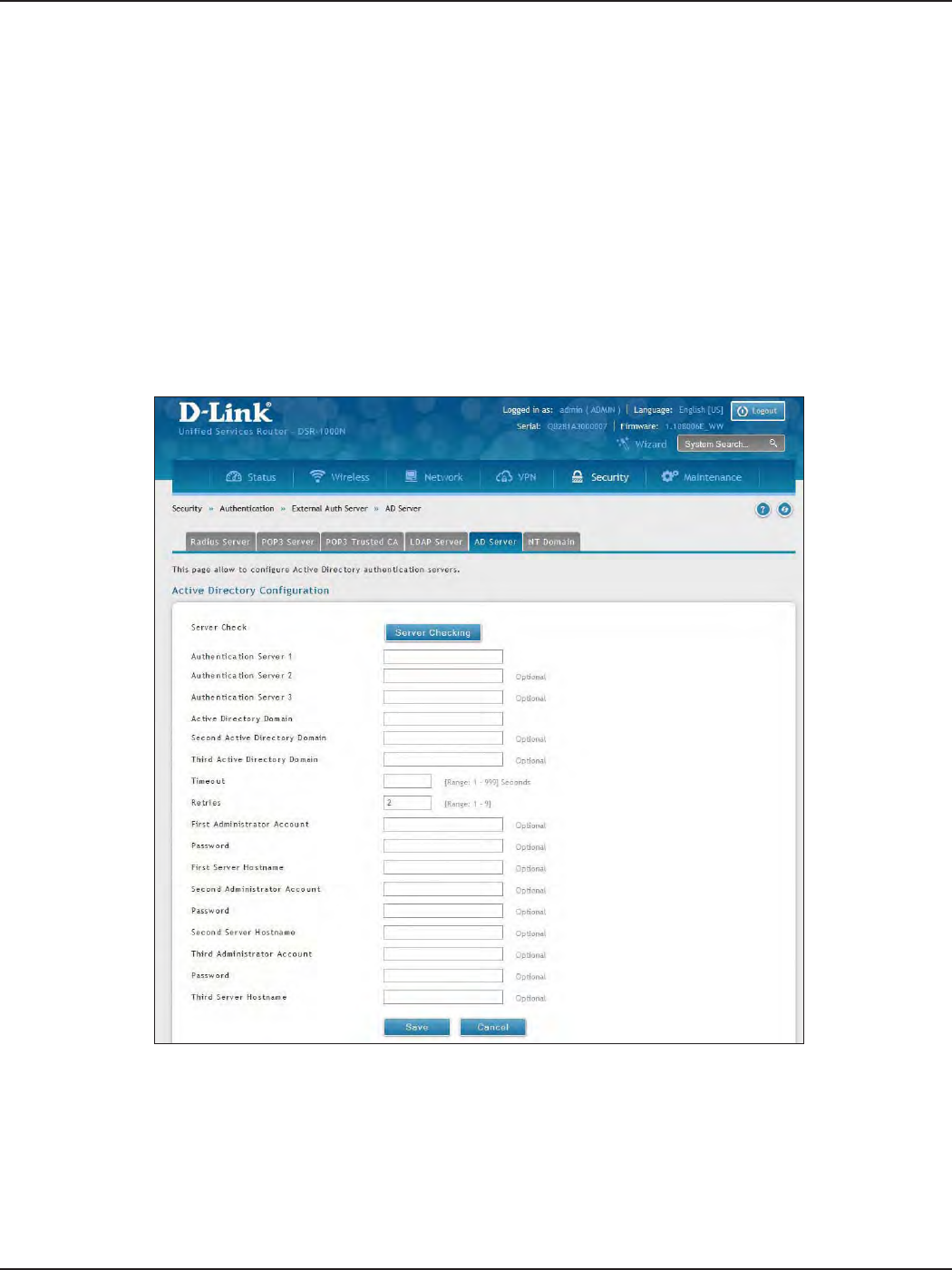
D-Link DSR-Series User Manual 136
Section 8 - Security
Path: Security > Authentication > External Auth Server > AD Server
Active Directory authentication is an enhanced version of NT Domain authentication. The Kerberos protocol is
leveraged for authentication of users, who are grouped in Organizational Units (OUs). In particular the Active
Directory server can support more than a million users given is structure while the NT Domain server is limited to
thousands. The congured Authentication Servers and Active Directory domain(s) are used to validate the user
with the directory of users on the external Windows based server. This authentication option is common for SSL
VPN client users and is also useful for IPsec / PPTP / L2TP client authentication.
To congure the router to connect to your AD server:
1. Click Security > Authentication > External Auth Server > AD Server tab.
AD Server
2. Complete the AD server information from the table on the next page and click Save. You can congure
up to three servers.

D-Link DSR-Series User Manual 137
Section 8 - Security
Field Description
Authentication Server (1-3) Enter the IP address of your AD server(s).
Active Directory Domain
(1-3) Enter the active directory domain name(s).
Timeout Set the amount of time in seconds that the router should wait for a response from the AD server.
Retries This determines the number of tries the controller will make to the AD server before giving up.
Administrator Account Enter the admin account information that will be used when authentication is required for PPTP/L2TP
connection.
Save Click Save at the bottom to save and activate your settings.
Server Check Click to test the connection(s) to your AD Server(s).
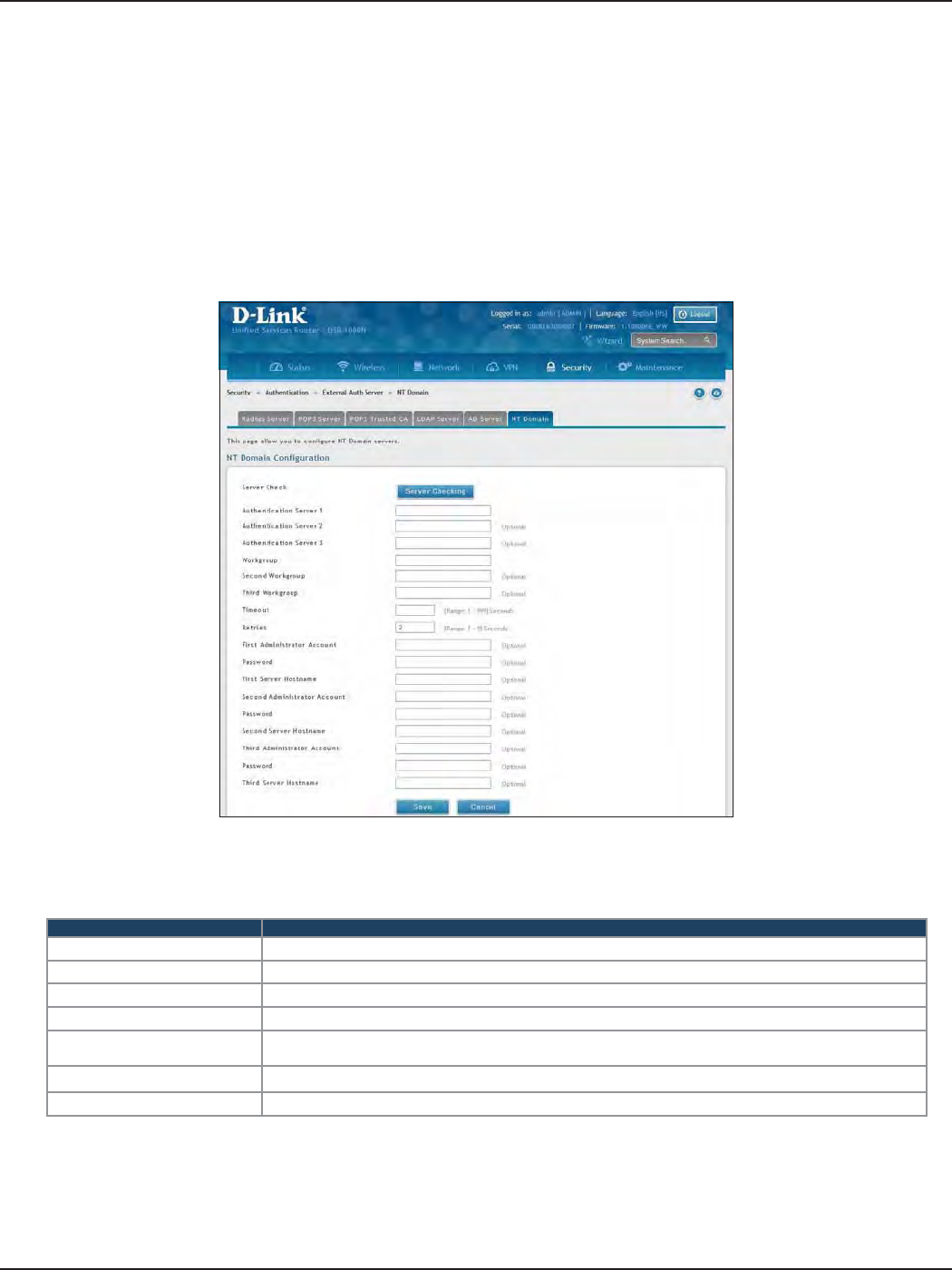
D-Link DSR-Series User Manual 138
Section 8 - Security
Path: Security > Authentication > External Auth Server > NT Domain
The NT Domain server allows users and hosts to authenticate themselves via a pre-congured Workgroup
eld. Typically Windows or Samba servers are used to manage the domain of authentication for the centralized
directory of authorized users.
To congure the router to connect to your NT domain server:
1. Click Security > Authentication > External Auth Server > NT Domain tab.
NT Domain Server
2. Complete the NT server information from the table below and click Save. You can congure up to
three servers.
Field Description
Authentication Server (1-3) Enter the IP address of your NT server(s).
Workgroup (1-3) Enter the NT workgroup name(s).
Timeout Set the amount of time in seconds that the router should wait for a response from the AD server.
Retries This determines the number of tries the controller will make to the AD server before giving up.
Administrator Account Enter the admin account information that will be used when authentication is required for PPTP/L2TP
connection.
Save Click Save at the bottom to save and activate your settings.
Server Check Click to test the connection(s) to your AD Server(s).
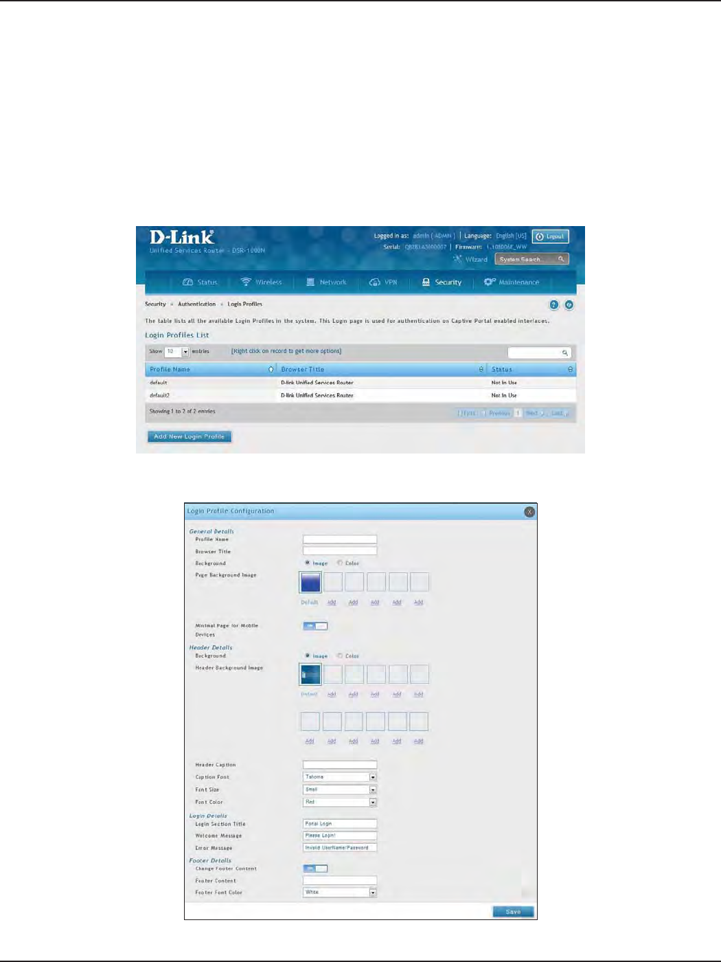
D-Link DSR-Series User Manual 139
Section 8 - Security
Path: Security > Authentication > Login Proles
When a wireless client connects to the SSIDs or VLANs, the user sees a login page. The Login Prole and SLA page
allows you to customize the appearance of that page with specic text and images. The wireless router supports
multiple login and SLA pages. Associate login page or SLAs on SSIDs or VLANs separately.
To add, delete, or edit login proles:
1. Click Security > Authentication > Login Proles tab.
Login Proles
3. Complete the elds from the table on the next page and click Save.
2. Right-click an entry and select either Edit or Delete. To add a new group, click Add New Login Prole.

D-Link DSR-Series User Manual 140
Section 8 - Security
Field Description
General Details
Prole Name Enter a name for this captive portal prole. The name should allow you to dierentiate this captive prole from
others you may set up.
Browser Title Enter the text that will appear in the title of the browser during the captive portal session.
Background
Select whether the login page displayed during the captive portal session will show an image or color. Choices are:
• Image: Displays an image as the background on the page. Use the Page Background Image eld to select a
background image.
• Color: Sets the background color on the page. Select the color from the drop-down menu
Page Background Image If you set Background to Image, upload the image le by clicking Add > Browse. Select an image, click Open and
then click the Upload button. The maximum size of the image is 100 kb.
Page Background Upload Choose the le you want to upload.
Page Background Color If you set Background to Color, select the background color of the page that will appear during the captive portal
session from the drop-down menu.
Custom Color If you choose Custom on Page Background Color, enter the HTML color code.
Minimal Page for Mobile
Devices Toggle to ON to allow the web page to be properly viewed from a mobile device.
Header Details
Background
Select whether the login page displayed during the captive portal session will show an image or color. Choices are:
• Image: Show image on the page. Use the Header Background Color eld to select a background color. The
maximum size of the image is 100 kb.
• Color: Show background color on the page. Use the radio buttons to select an image.
Header Background Image If you set Background to Image, upload the image le by clicking Add > Browse. Select an image, click Open and
then click the Upload button. The maximum size of the image is 100 kb.
Header Background Upload Choose the le you want to upload.
Header Background Color If you set Background to Color, select the header color from the drop-down menu.
Custom Color If you choose Custom on Page Background Color, you can choose particular color by lling in the HTML color code.
Header Caption Enter the text that appears in the header of the login page during the captive portal session.
Caption Font Select the font for the header text.
Font Size Select the font size for the header text.
Font Color Select the font color for the header text.
Login Details
Login Section Title Enter the text that appears in the title of the login box when the user logs in to the captive portal session. This eld
is optional.
Welcome Message Enter the welcome message that appears when users log in to the captive session successfully. This eld is optional.
Error Message Enter the error message that appears when users fail to log in to the captive session successfully. This eld is
optional.
Footer Details
Change Footer Content Enables or disables changes to the footer content on the login page.
Footer Content If Change Footer Content is checked, enter the text that appears in the footer.
Footer Font Color If Change Footer Content is checked, select the color of the text that appears in the footer.

D-Link DSR-Series User Manual 141
Section 8 - Security
External Payment Gateway
Enable External Payment
Gateway Enables or disables external payment gateway and online wireless service purchasing from on the login page.
Session Title 1 Enter the text that appears in the title of the online purchasing login box when the user logs in to the captive portal
session.
Message Enter the text appears in the online purchasing login box when the user logs in to the captive portal session.
Session Title 2 Enter the text that appears in the title of the message box while online purchasing is complete.
Success Message Enter the text that appears in the message box while online purchasing is complete.
Session Title 3 Enter the text that appears in the title of the message box while online purchasing is fail.
Failure Message Enter the text that appears in the message box while online purchasing is fail.
Enable Billing Prole Select the billing prole which will be shown on the login page. The table only listed the billing proles which are
set Unit Price. Enable the billing prole by switch ON on STATUS.
Service Disclaimer Text Enter the service disclaimer text which is shown before user select and purchase wireless service.
Payment Server Select the payment received account and its payment agent.
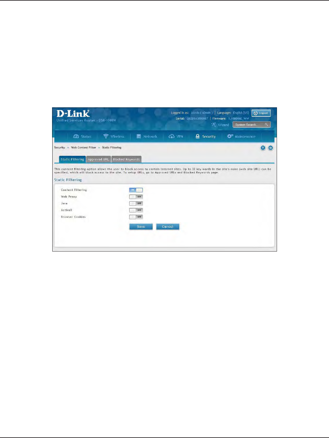
D-Link DSR-Series User Manual 142
Section 8 - Security
Path: Security > Authentication > Static Filtering
You may block access to certain Internet services.
To block or allow a service:
1. Click Security > Web Content Filter > Static Filtering tab.
Static Filtering
Web Content Filtering
2. Toggle Content Filtering to ON.
3. Toggle the service to ON to block. Toggle to OFF to allow.
4. Click Save.
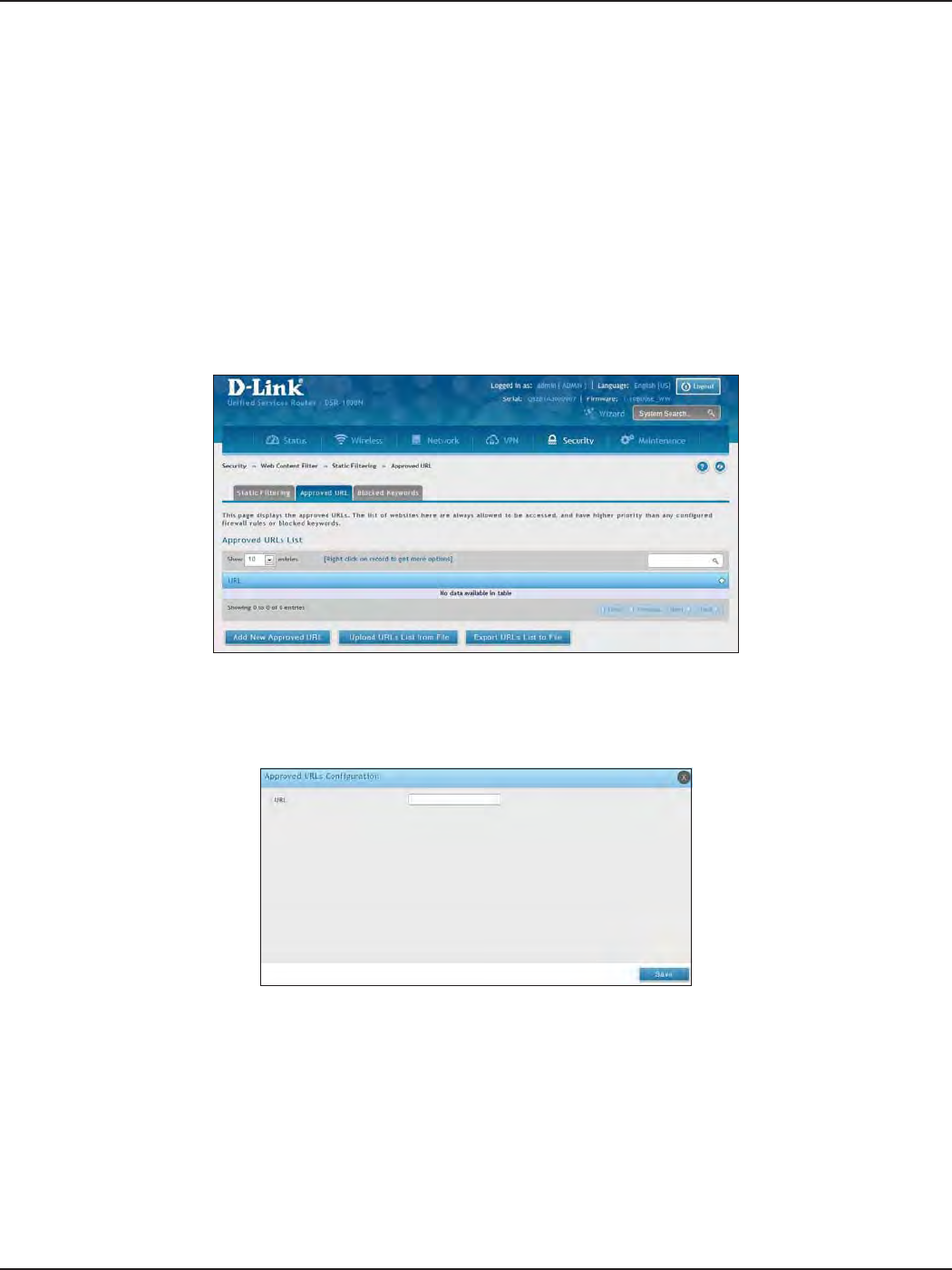
D-Link DSR-Series User Manual 143
Section 8 - Security
Path: Security > Web Content Filter > Static Filtering > Approved URL
The approved URL list is an acceptance list for all URL domain names. Domains added to this list are allowed
in any form. For example, if the domain “dlink” is added to this list then all of the following URL’s are permitted
access from the LAN: www.dlink.com, support.dlink.com, etc.
Importing/exporting from a text or CSV le is also supported.
To add/import/export URLs to the approved list:
1. Click Security > Web Content Filter > Static Filtering > Approved URL tab.
Approved URLs
2. To import a list from a text/CSV le, click Upload URLs List from File. If you want to export the current
list, click Export URLs List to File. To add a new URL, click Add New Approved URL.
3. Enter a URL and click Save.
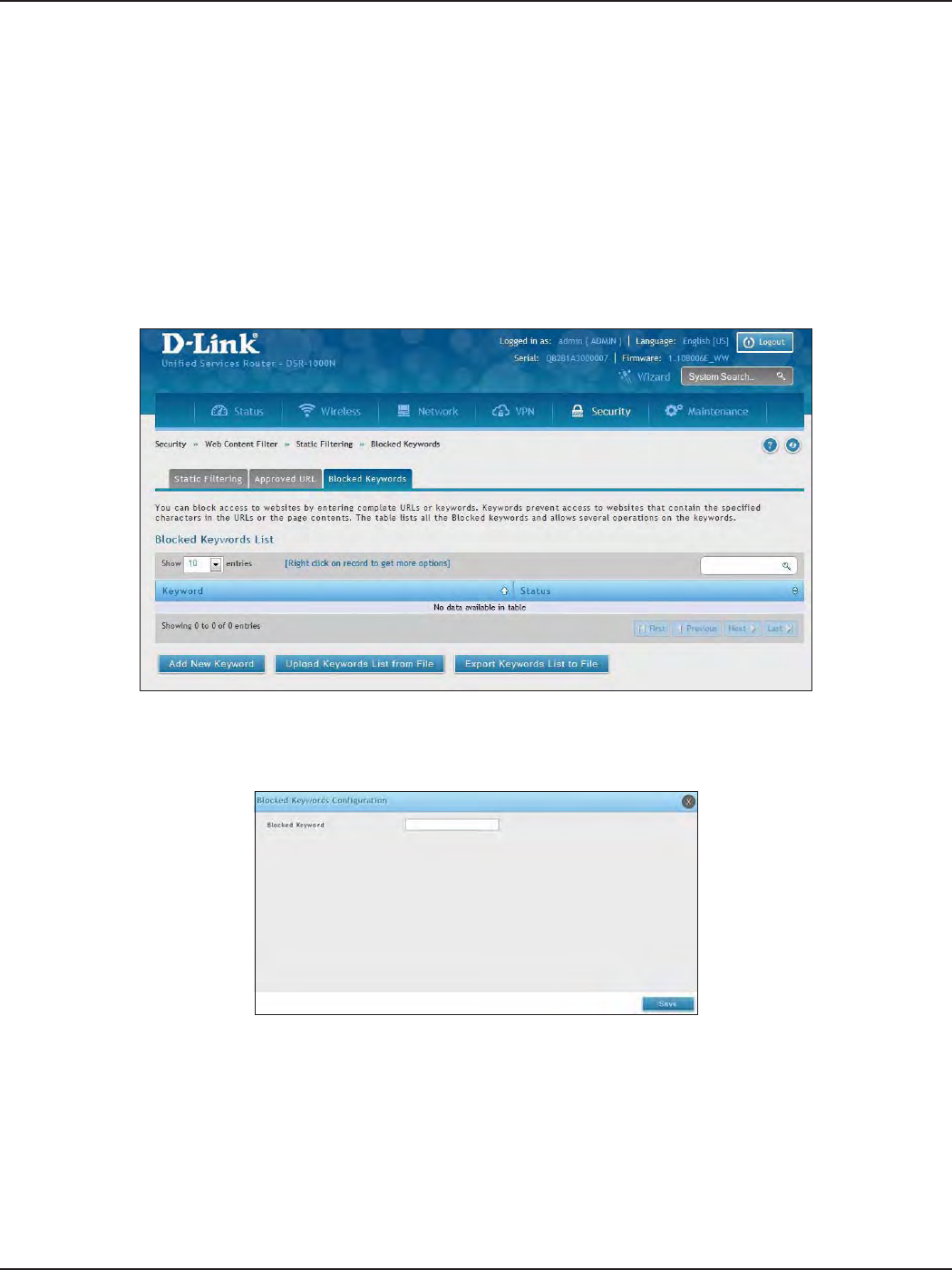
D-Link DSR-Series User Manual 144
Section 8 - Security
Path: Security > Web Content Filter > Static Filtering > Blocked Keywords
Keyword blocking allows you to block all website URL’s or site content that contains the keywords in the
congured list. This is lower priority than the Approved URL List; i.e. if a blocked keyword is present in a site
allowed by a trusted domain in the Approved URL List, then access to that site will be allowed. Import/export
from a text or CSV le is also supported.
To add/import/export URLs to the approved list:
1. Click Security > Web Content Filter > Static Filtering > Blocked Keywords tab.
Blocked Keywords
2. To import a list from a text/CSV le, click Upload Keywords List from File. If you want to export the
current list, click Export Keywords List to File. To add a new URL, click Add New Keyword.
3. Enter a keyword and click Save.
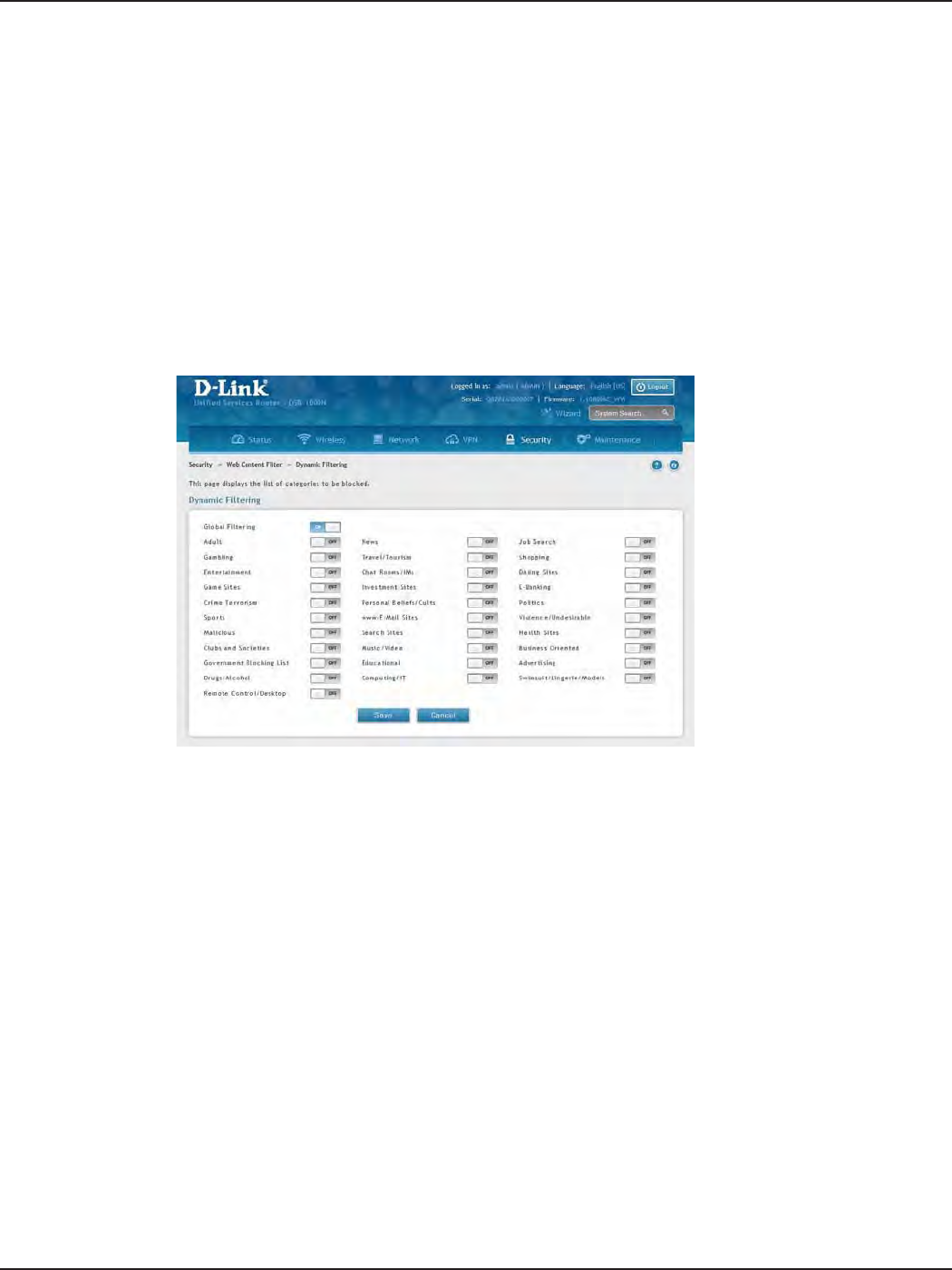
D-Link DSR-Series User Manual 145
Section 8 - Security
Path: Security > Web Content Filter > Dynamic Filtering
Dynamic Filtering will allow you to lter content from a list of categories. The router must be upgraded with the
WCF license and then the Content Filtering option, which allows the user to lter out internet sites, needs to be
enabled. When enabled, access to a website belonging to one of these congured categories will be blocked
with an error page.
To add/import/export URLs to the approved list:
1. Click Security > Web Content Filter > Dynamic Filtering.
Dynamic Filtering
2. Toggle Global Filtering to ON to enable dynamic ltering.
3. Toggle any of the listed categories to ON to block. Toggle to OFF to allow.
4. Click Save.
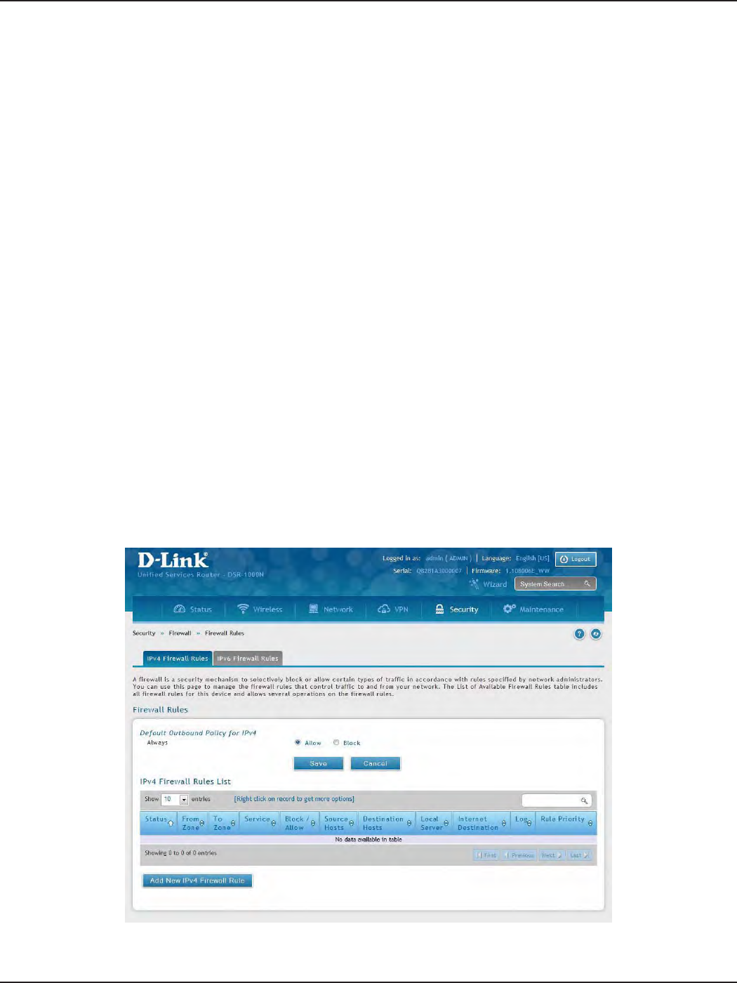
D-Link DSR-Series User Manual 146
Section 8 - Security
Path: Security > Firewall > Firewall Rules > IPv4 Firewall Rules or IPv6 Firewall Rules
Inbound (WAN to LAN/DMZ) rules restrict access to trac entering your network, selectively allowing only
specic outside users to access specic local resources. By default all access from the insecure WAN side are
blocked from accessing the secure LAN, except in response to requests from the LAN or DMZ. To allow outside
devices to access services on the secure LAN, you must create an inbound rewall rule for each service.
If you want to allow incoming trac, you must make the router’s WAN port IP address known to the public. This is
called “exposing your host.” How you make your address known depends on how the WAN ports are congured;
for this router you may use the IP address if a static address is assigned to the WAN port, or if your WAN address
is dynamic a DDNS (Dynamic DNS) name can be used.
Outbound (LAN/DMZ to WAN) rules restrict access to trac leaving your network, selectively allowing only
specic local users to access specic outside resources. The default outbound rule is to allow access from
the secure zone (LAN) to either the public DMZ or insecure WAN. On other hand the default outbound rule
is to deny access from DMZ to insecure WAN. You can change this default behavior in the Firewall Settings >
Default Outbound Policy page. When the default outbound policy is allow always, you can to block hosts on
the LAN from accessing internet services by creating an outbound rewall rule for each service.
To create a new rewall rule:
1. Click Security > Firewall > IPv4 Firewall Rules tab or IPv6 Firewall Rules tab.
Firewall
Firewall Rules
2. Right-click an entry and select either Edit or Delete. To add a new group, click Add New IPv4/IPv6
Firewall Rule.
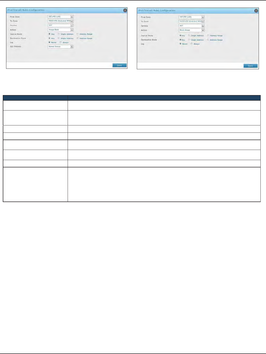
D-Link DSR-Series User Manual 147
Section 8 - Security
3. Complete the elds from the table below and click Save.
Field Description
From Zone Select the source of originating trac: either secure LAN, public DMZ, or insecure WAN. For an inbound rule
WAN should be selected.
To Zone
Select the destination of trac covered by this rule. If the From Zone is the WAN, the To Zone can be the
public DMZ or secure LAN. Similarly if the From Zone is the LAN, then the To Zone can be the public DMZ
or insecure WAN.
Service Select a service from the drop-down menu. ANY means all trac is aected by this rule.
Action Select an action from the drop-down menu.
Source Hosts Select a source host. If you select Single Address or Address Range, you will need to enter the IP address or
IP range.
Destination Hosts Select a Destination host. If you select Single Address or Address Range, you will need to enter the IP address
or IP range.
Log Select whether to log rewall trac or not.
QoS Priority (IPv4 only)
Outbound rules (where To Zone = insecure WAN only) can have the trac marked with a QoS priority tag.
Select a priority level:
• Normal-Service: ToS=0 (lowest QoS)
• Minimize-Cost: ToS=1
• Maximize-Reliability: ToS=2
• Maximize-Throughput: ToS=4
• Minimize-Delay: ToS=16