D Link TW1130 Wireless VPN Router User Manual di714P manual 1 31
D Link Corporation Wireless VPN Router di714P manual 1 31
UserManual.wiki
>
D Link
>
TW1130 User Manual
>
User Manual Part 2
Contents
1.
User Manual Part 1
2.
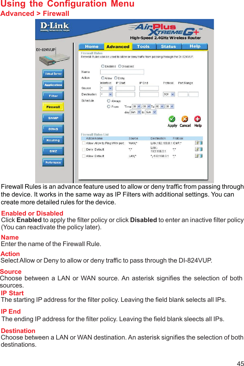
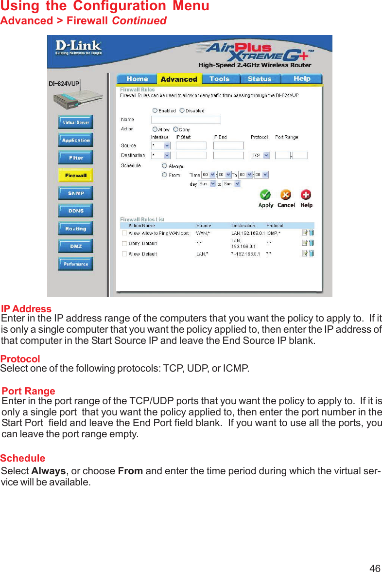
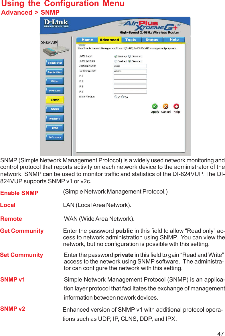
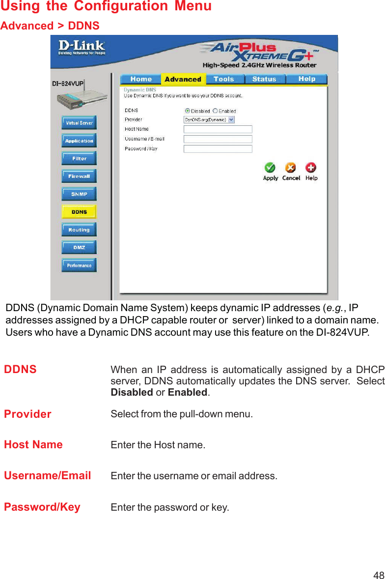
User Manual Part 2
3.
User Manual Part 3
4.
User Manual Part 4
5.
User Manual Part 5
6.
User Manual Part 6
7.
User Manual Part 7
User Manual Part 2
Navigation menu
Upload a User Manual
Namespaces
Wiki Guide
HTML
PDF
Info
Views
User Manual
Discussion / Help
Navigation