D Link TW1130 Wireless VPN Router User Manual di714P manual 1 31
D Link Corporation Wireless VPN Router di714P manual 1 31
D Link >
Contents
User Manual Part 2
29
Using the Configuration Menu
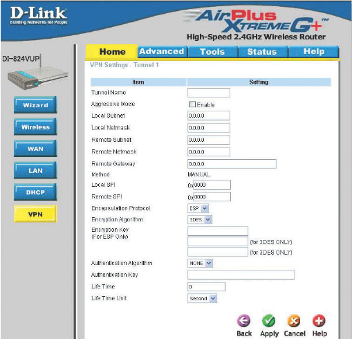
Home > VPN Settings > Tunnel > Manual
Remote Subnet The subnet of the remote VPN gateway’s local network. It
can be a host, a partial subnet, or a whole subnet.
Remote Netmask The subnet of the remote VPN gateway’s local network.
It can be a host, a partial subnet, or a whole subnet.
Remote Gateway The WAN IP address of remote VPN gateway.
Local Subnet The subnet of the VPN gateway’s local network. It can be a
host, a partial subnet, or a whole subnet.
Local Netmask Local netmask combined with local subnet to form a subnet
domain.
Aggressive Mode Enabling this mode will accelerate establishing tunnel, but
the device will have less security.
Tunnel Name Current tunnel name.
Remote SPI The value of the remote SPI should be set in hex format.
Local SPI The value of the local SPI should be set in hex format.
Method The set of rules applied when connecting to the VPN gateway.

30
Using the Configuration Menu
Home > VPN Settings > Tunnel > Manual Continued...
Encapsulation
Protocol
There are two protocols that can be selected: ESP and AH.
Encryption
Algorithm
There are two algorithms that can be selected: 3DES and DES.
Authentication
Algorithm
There are two algorithms that can be selected: SHA1 and MD5.
Encryption Key For DES, the encryption key is 8 bytes (16 Char.). For 3DES,
the encryption key is 24 bytes (48 Char.).
Authentication Key For MD5, the authentication algorithm is16 bytes (32 Char.).
For SHA1, the authentication algorithm is 20 bytes.(40 Char.).
Life Time Enter in the life time value.
Life Time Unit There are two units that can be selected: Second and KB.
31
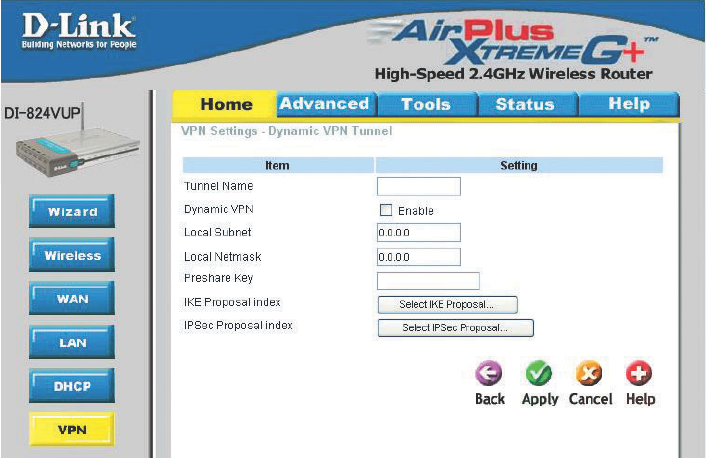
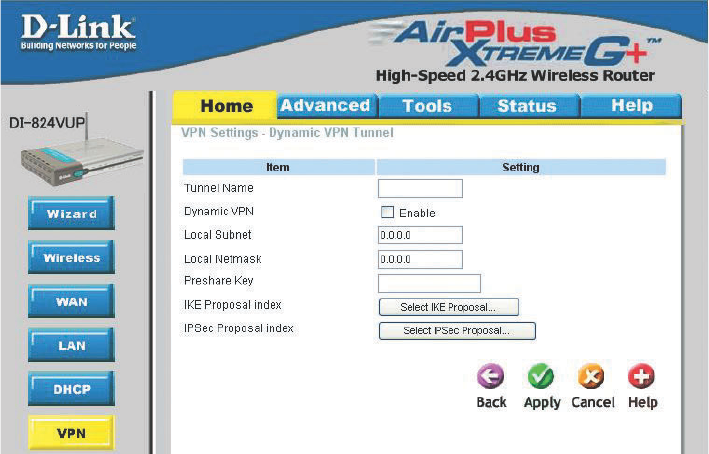
Home > VPN Settings > Dynamic VPN Tunnel
Using the Configuration Menu
Local Subnet The subnet of the VPN gateway’s local network. It can be a
host, a partial subnet, or a whole subnet.
Local Netmask The netmask of the VPN gateway’s local network.
Aggressive Mode Enabling this mode will accelerate establishing the tunnel,
but the device will have less security.
Tunnel Name Current tunnel name.
This feature works with a VPN software client so the DI-
824VUP does not need to know the IP address of the remote
clients.
Dynamic VPN
There are three parts that are necessary to setup the
configuration of IKE for the dedicated tunnel: basic setup, IKE
proposal setup, and IPSec proposal setup. Basic setup
includes the setting of following items: local subnet, local
netmask, remote subnet, remote netmask, remote gateway,
and pre-shared key. The tunnel name is derived from the
previous page of VPN setting. IKE proposal setup includes
the setting of a set of frequent-used IKE proposals and selecting
from the set of IKE proposals.
VPN Settings - IKE
32
Using the Configuration Menu
Home > VPN Settings > Dynamic VPN Tunnel Continued...
Preshared Key The first key that supports IKE mechanism of both VPN
gateways for negotiating further security keys. The pre-
shared key must be the same for both endpoint gateways.
IKE Proposal index Click the button to setup a set of frequent-used IKE
proposals and select from the set of IKE proposals for the
dedicated tunnel.
IPSec Proposal
index
Click the button to setup a set of frequent-used IPSec
proposals and select from the set of IKE proposals for the
dedicated tunnel.
33
Using the Configuration Menu
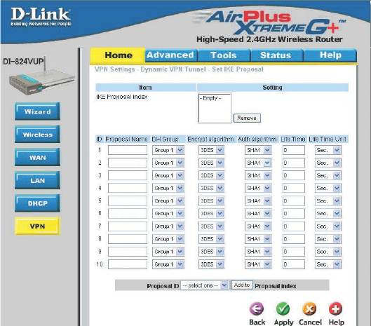
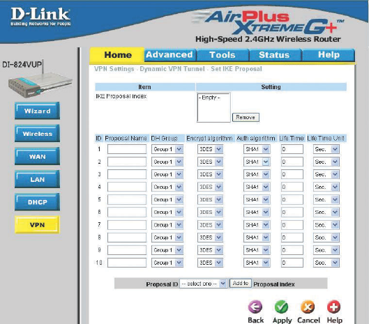
Home > VPN Settings > Dynamic VPN Tunnel > Set IKE Proposal
IKE Proposal index
Proposal Name
DH Group
Encrypt algorithm
Auth algorithm
A list of selected proposal indexes from the IKE proposal
pool listed below.
There are three groups that can be selected: group 1
(MODP768), group 2 (MODP1024), and group 5
(MODP1536).
There are two algorithms that can be selected: 3DES and
DES.
It indicates which IKE proposal to be focused.
There are two algorithms that can be selected: SHA1 and
MD5.
34
Life Time Enter in the life time value.
Life Time Unit There are two units that can be selected: second and KB.
Proposal ID The identifier of IKE proposal can be chosen for adding the
corresponding proposal to the dedicated tunnel.
Add to Click it to add the chosen proposal indicated by proposal ID
to IKE Proposal index list.
Using the Configuration Menu
Home > VPN Settings > Dynamic VPN Tunnel > Set IKE Proposal
Continued...
35
Using the Configuration Menu
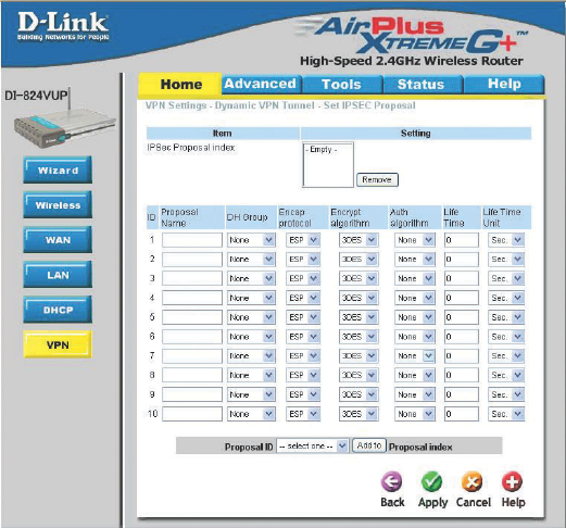
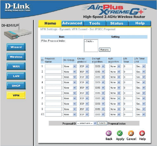
Home > VPN Settings > Dynamic VPN Tunnel > Set IPSEC Proposal
IPSec Proposal
index
A list of selected proposal indexes from the IPSec proposal
pool listed below.
Proposal Name
DH Group There are three groups that can be selected: group 1
(MODP768), group 2 (MODP1024), and group 5
(MODP1536).
Encap protocol There are two protocols that can be selected: ESP and AH.
Encrypt algorithm There are two algorithms that can be selected: 3DES and
DES.
This is the name used to classify the IPSec proposal.
Auth algorithm There are two algorithms that can be selected: SHA1 and
MD5.
36
Using the Configuration Menu
Home > VPN Settings > Dynamic VPN Tunnel > Set IPSEC Proposal
Continued...
Life Time Enter in a life time value.
Life Time Unit There are two units that can be selected: second and KB.
Proposal ID The identifier of IPSec proposal can be chosen for adding the
corresponding proposal to the dedicated tunnel.
Add to Click it to add the chosen proposal indicated by proposal ID
to IPSec Proposal index list.
37
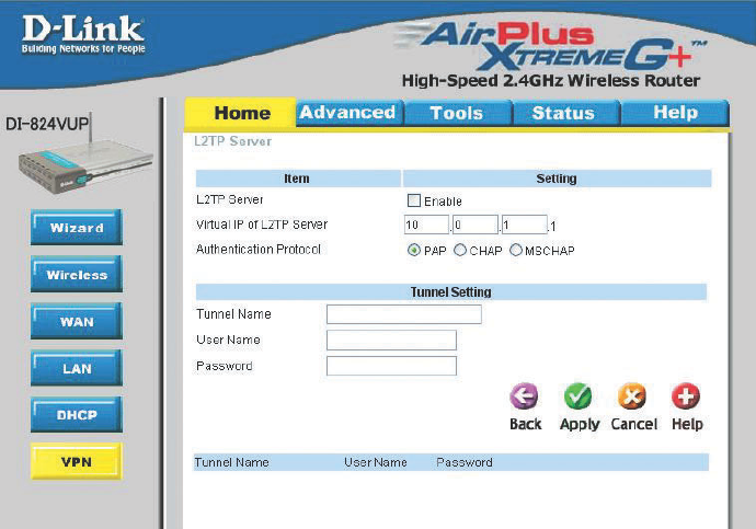
Home > VPN Settings > L2TP Server Setting
Using the Configuration Menu
Enable L2TP
Server
Click to enable the L2TP Server function.
Virtual IP of
L2TP Server
Enter your Virtual IP address to access the L2PT server.
Authentication
Protocol
Select one of the following authentication protocols: PAP,
CHAP, or MSCHAP.
Tunnel Name Current tunnel name.
User Name
Password Enter in the password for the L2TP account.
Enter in the username for the L2TP account.
38
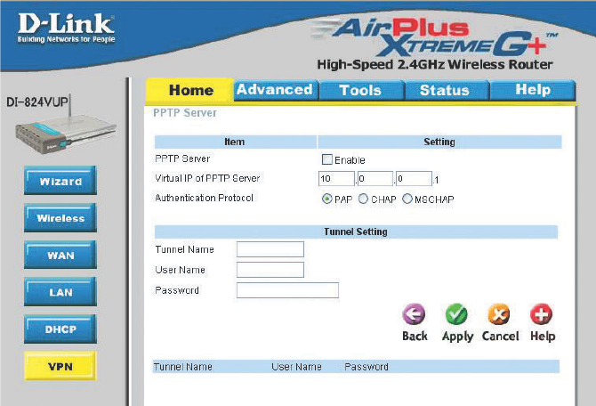
Home > VPN Settings > PPTP Server Setting
Using the Configuration Menu
Enable PPTP
Server
Click to enable the PPTP Server function.
Virtual IP of
PPTP Server
Enter your Virtual IP address to access thePPPT server.
Authentication
Protocol
Select one of the following authentication protocols: PAP,
CHAP, or MSCHAP.
Tunnel Name Current tunnel name.
User Name
Password Enter in the password for the PPTP account.
Enter in the username for the PPTP account.
39
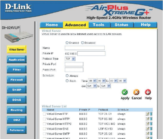
Advanced > Virtual Server
Using the Configuration Menu
The DI-824VUP can be configured as a virtual server so that remote users accessing
Web or FTP services via the public IP address can be automatically redirected to local
servers in the LAN (Local Area Network).
The DI-824VUP firewall feature filters out unrecognized packets to protect your LAN
network so all computers networked with the DI-824VUP are invisible to the outside
world. If you wish, you can make some of the LAN computers accessible from the
Internet by enabling Virtual Server. Depending on the requested service, the DI-824VUP
redirects the external service request to the appropriate server within the LAN network.
Protocol Type The protocol used for the virtual service.
Public Port The port number on the WAN side that will be used to access
the virtual service.
Private IP The server computer in the LAN network that will be providing
the virtual services.
Name The name referencing the virtual service.
Private Port The port number of the service used by the Private IP computer.
Schedule Select Always, or choose From and enter the time period dur-
ing which the virtual service will be available.
40
Using the Configuration Menu
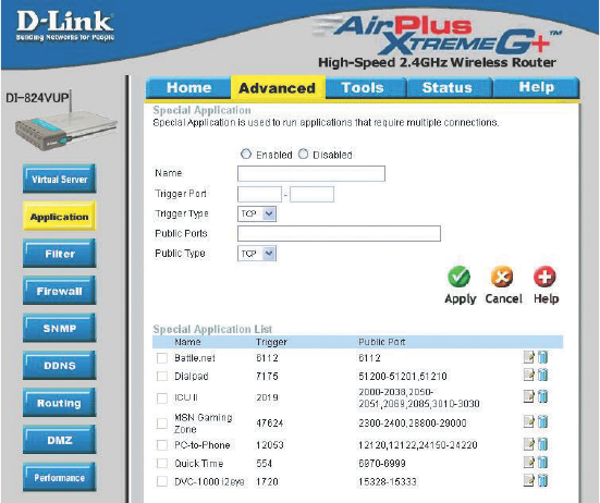
Advanced > Application
Some applications require multiple connections, such as Internet gaming, video
conferencing, Internet telephony, and others. These applications have difficulties working
through NAT (Network Address Translation). Special Applications makes some of these
applications work with the DI-824VUP. If you need to run applications that require multiple
connections, specify the port normally associated with an application in the Trigger
field, then enter the public ports associated with the trigger port into the Incoming
Ports field.
At the bottom of the screen, there are already defined special applications. To use them,
select one from the drop down list and select an ID number you want to use. Then click
the “Copy to” button and the router will fill in the appropriate information to the list. You
will then need to enable the service. If the mechanism of Special Applications fails to
make an application work, try using DMZ host instead.
Note! Only one PC can use each Special Application tunnel.
Trigger Port This is the port used to trigger the application. It can be
either a single port or a range of ports.
Public Ports This is the port number on the WAN side that will be used to
access the application. You may define a single port or a range
of ports. You can use a comma to add multiple ports or port
ranges.
Enabled Select to activate the policy.
41
Using the Configuration Menu
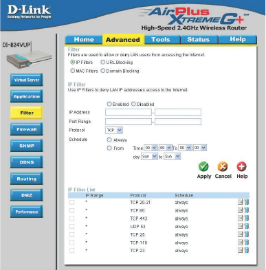
Advanced > Filter > IP Filter
IP Filter
Use IP Filters to deny LAN IP addresses access to the internet.
Protocol
IP Address
Enter in the IP address range of the computers that you want the policy to apply to. If it
is only a single computer that you want the policy applied to, then enter the IP address of
that computer in the Start Source IP and leave the End Source IP blank.
Use IP (Internet Protocol)
filters to allow or deny
computers access to the
Internet based on their IP
address.
Port Range
Enter in the port range of the TCP/UDP ports that you want the policy to apply to. If it is
only a single port that you want the policy applied to, then enter the port number in the
Start Port field and leave the End Port field blank. If you want to use all the ports, you
can leave the port range empty.
Enabled or Disabled
Click Enabled to apply the filter policy or click Disabled to enter an inactive filter policy.
(You can reactivate the policy later.)
Select the protocol type to allow or deny certain types of IP addresses.
Schedule
Select Always, or choose From and enter the time period during which the IP filter policy
will be in effect.
42
Using the Configuration Menu
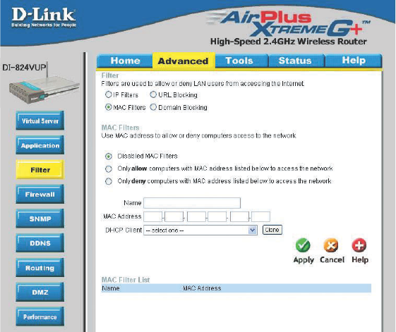
Advanced > Filter > MAC Filters
MAC (Media Access Control) Filters are used to allow or deny LAN (Local Area Network)
computers from accessing the Internet and network by their MAC address.
At the bottom of the screen, there is a list of MAC addresses from the DHCP client
computers connected to the DI-824VUP. To use them, select one from the drop down
list. Then click the “Apply” button and the DI-824VUP will fill in the appropriate information
to the list.
Disabled MAC Filter
Select this option if you do not want to use MAC filters.
Only allow computers with MAC address listed below to access the network
Select this option to only allow computers that are in the list to access the network
and Internet. All other computers will be denied access to the network and
Internet.
Only deny computers with MAC address listed below to access the network
Select this option to only deny computers that are in the list to access the network
and Internet. All other computers will be allowed access to the network and Internet.
Enter the MAC Address of the client that will be filtered.
MAC Address
43
Using the Configuration Menu
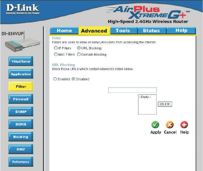
Advanced > Filter > URL Blocking
Use URL Blocking to deny LAN computers from accessing specific web sites by its
URL. A URL is a specially formatted text string that defines a location on the Internet.
If any part of the URL contains the blocked word, the site will not be accessible and
the web page will not display.
Disabled URL Blocking
Select this option if you do not want to use URL Blocking.
44
Using the Configuration Menu
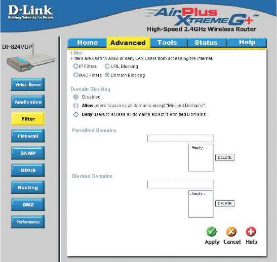
Advanced > Filter > Domain Blocking
Use Domain Blocking to allow or deny computers access to specific Internet domains
whether it is through www, ftp, snmp, etc.
Disabled Domain Blocking
Select this option if you do not want to use Domain Blocking.
Allow users to access all domains except “Blocked Domains”
Select this option to allow users to access the specified Internet domains listed below.
Users will be denied access to all other Internet domains.
Deny users to access all domains except “Permitted Domains”
Select this option to deny users to access the specified Internet domains listed below.
Users will be allowed access to all other Internet domains.
45
Using the Configuration Menu
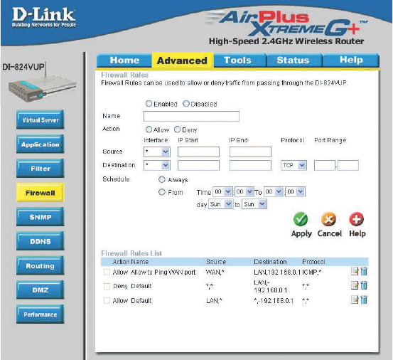
Advanced > Firewall
Firewall Rules is an advance feature used to allow or deny traffic from passing through
the device. It works in the same way as IP Filters with additional settings. You can
create more detailed rules for the device.
Enabled or Disabled
Click Enabled to apply the filter policy or click Disabled to enter an inactive filter policy
(You can reactivate the policy later).
Name
Enter the name of the Firewall Rule.
Action
Select Allow or Deny to allow or deny traffic to pass through the DI-824VUP.
Source
Choose between a LAN or WAN source. An asterisk signifies the selection of both
sources.
IP Start
The starting IP address for the filter policy. Leaving the field blank selects all IPs.
IP End
The ending IP address for the filter policy. Leaving the field blank sleects all IPs.
Destination
Choose between a LAN or WAN destination. An asterisk signifies the selection of both
destinations.

46
Using the Configuration Menu
Advanced > Firewall Continued
Schedule
Select Always, or choose From and enter the time period during which the virtual ser-
vice will be available.
IP Address
Enter in the IP address range of the computers that you want the policy to apply to. If it
is only a single computer that you want the policy applied to, then enter the IP address of
that computer in the Start Source IP and leave the End Source IP blank.
Port Range
Enter in the port range of the TCP/UDP ports that you want the policy to apply to. If it is
only a single port that you want the policy applied to, then enter the port number in the
Start Port field and leave the End Port field blank. If you want to use all the ports, you
can leave the port range empty.
Protocol
Select one of the following protocols: TCP, UDP, or ICMP.
47
Using the Configuration Menu
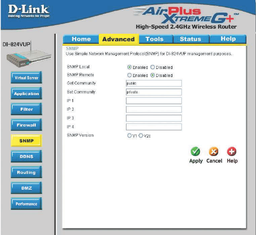
Advanced > SNMP
SNMP (Simple Network Management Protocol) is a widely used network monitoring and
control protocol that reports activity on each network device to the administrator of the
network. SNMP can be used to monitor traffic and statistics of the DI-824VUP. The DI-
824VUP supports SNMP v1 or v2c.
Enable SNMP
Get Community
(Simple Network Management Protocol.)
Enter the password public in this field to allow “Read only” ac-
cess to network administration using SNMP. You can view the
network, but no configuration is possible wth this setting.
Set Community Enter the password private in this field to gain “Read and Write”
access to the network using SNMP software. The administra-
tor can configure the network with this setting.
Local
Remote WAN (Wide Area Network).
LAN (Local Area Network).
SNMP v1 Simple Network Management Protocol (SNMP) is an applica-
tion layer protocol that facilitates the exchange of management
information between nework devices.
SNMP v2 Enhanced version of SNMP v1 with additional protocol opera-
tions such as UDP, IP, CLNS, DDP, and IPX.
48
Using the Configuration Menu
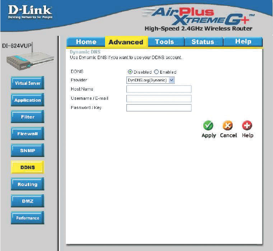
Advanced > DDNS
DDNS (Dynamic Domain Name System) keeps dynamic IP addresses (e.g., IP
addresses assigned by a DHCP capable router or server) linked to a domain name.
Users who have a Dynamic DNS account may use this feature on the DI-824VUP.
DDNS When an IP address is automatically assigned by a DHCP
server, DDNS automatically updates the DNS server. Select
Disabled or Enabled.
Provider Select from the pull-down menu.
Host Name Enter the Host name.
Username/Email Enter the username or email address.
Password/Key Enter the password or key.
49
Using the Configuration Menu
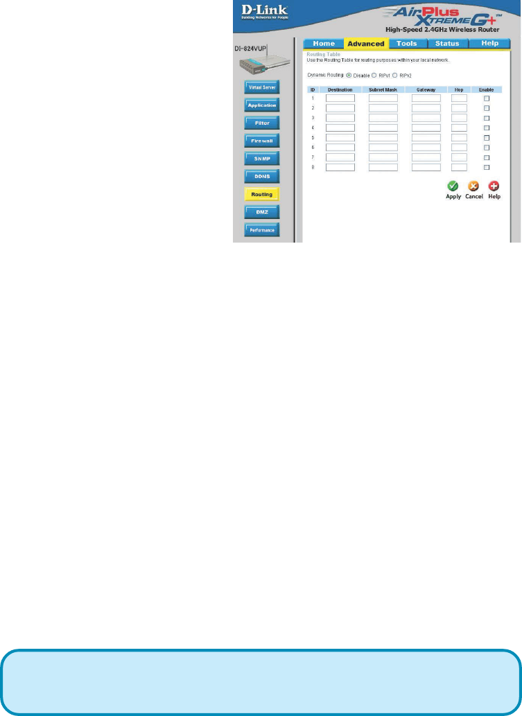
Advanced > Routing
Static routes can be added if
you require specific routes
within your internal network.
These routes will not apply to
the WAN (Internet) network.
Enable Select this option for the specified static route to take effect.
Hop Count - In a transmission path, each link is terminated at a network device
such as a router or gateway. The number of hops equals the number of routers or
gateways that data must pass through before reaching the destination.
Dynamic Routing Settings allow the VPN Router to route IP
packets to another network automatically. The RIP protocol is
applied, and broadcasts the routing information to other routers
on the network regularly.
Dynamic Routing
RIP v1 Protocol in which the IP address is routed through the internet.
RIP v2 Enhanced version of RIP v1with added features such as Au-
thentication, Routing Domain, Next Hop Fowarding, and Subnet-
mask Exchange.
Destination Enter in the IP of the specified network that you want to
access using the static route.
Subnet Mask Enter in the subnet mask to be used for the specified net
work.
Gateway Enter in the gateway IP address to the specified network.
Hop Enter in the amount of hops it will take to the specified
network.
By default, it is set to disable. Check to enable (RIPv1 / RIPv2)
protocol.
50
Using the Configuration Menu
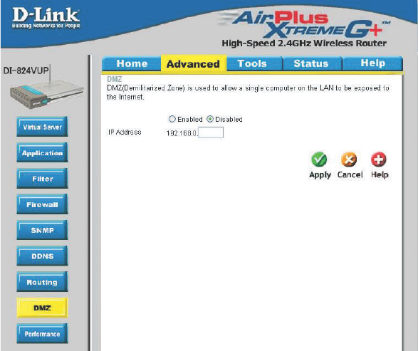
Advanced > DMZ
If you have a computer that cannot run Internet applications properly from behind the DI-
824VUP, then you can allow that computer to have unrestricted Internet access. Enter
the IP address of that computer as a DMZ (Demilitarized Zone) host with unrestricted
Internet access. Adding a client to the DMZ may expose that computer to a variety of
security risks; so only use this option as a last resort.
51
Using the Configuration Menu
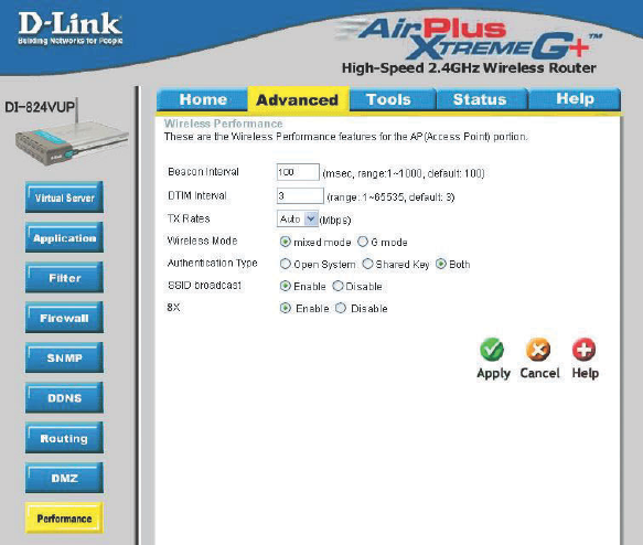
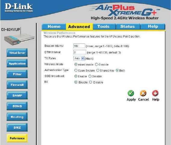
Advanced > Performance
Beacon Interval Beacons are packets sent by an Access Point to synchronize a
wireless network. Specify a value. 100 is the default setting and is
recommended.
TX Rates Select the data rate. Default is 1-2-5.5-11-22-54Mbps.
DTIM interval (Delivery Traffic Indication Message) 3 is the default setting. A DTIM
is a countdown informing clients of the next window for listening to
broadcast and multicast messages.
Wireless Mode
G Mode
The DI-824VUP will use either B or G mode depending on which
mode has a stronger frequency.
Mixed Mode
The DI-824VUP will only use G mode.
Select either mix mode or G mode.
52
Shared Key In this mode, in order to access the DI-824VUP on the network,
the device must be listed in the MAC Address Control List.
Both In this mode, all devices on the network can access the
DI-824VUP.
Authentication Select Open system, Shared Key or Both.
SSID Broadcast Enable is the default setting. Choose Enable to broadcast the SSID
across the network. All devices on a network must share the same
SSID (Service Set Identifier) to establish communication. Choose
Disable if you do not wish to broadcast the SSID over the network.
The DI-824VUP will be visible to all devices on the network. This is
the default setting.
Open System
Using the Configuration Menu
Advanced > Performance (Continued)
8x Enable 8X Mode on the wireless client and the DI-824VUP to
increase data transmission speed. 8X Mode will only work with
wireless devices that also support 8X Mode.