D Link TW1130 Wireless VPN Router User Manual di714P manual 1 31
D Link Corporation Wireless VPN Router di714P manual 1 31
D Link >
Contents
User Manual Part 1

High-Speed Enhanced 2.4 GHz
Manual
Wireless VPN Router
Building Networks for People
10/01/2003
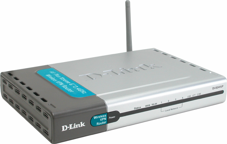
DI-824VUP
AirPlus Xtreme G
D-Link
2
Contents
Package Contents ................................................................................3
Introduction............................................................................................4
Wireless Basics ....................................................................................6
Getting Started ......................................................................................9
Using the Configuration Menu.............................................................. 11
Networking Basics ..............................................................................69
Reset to Factory Default Settings ........................................................98
Technical Specifications ......................................................................99
Frequently Asked Questions ..............................................................100
Contacting Technical Support ............................................................149
Warranty and Registration .................................................................150
Installing the Print Server Software ......................................................65
Configuring on Windows 98se/Me Platforms .......................................67
3
Contents of Package:
D-Link AirPlus Xtreme G DI-824VUP High-Speed Enhanced
2.4GHz Wireless VPN Router
Power Adapter – 5V DC / 2.5A
Manual on CD
Quick Installation Guide
Package Contents
Note: Using a power supply with a different voltage rating than the one included with the
DI-824VUP will cause damage and void the warranty for this product.
If any of the above items are missing, please contact your reseller.
System Requirements For Configuration:
Computer with Windows, Macintosh, or Linux-based
operating system with an installed Ethernet adapter
Internet Explorer version 6.0 or Netscape Navigator
version 6.0 and above, with JavaScript enabled
Ethernet-Based Cable or DSL Modem
4
Introduction
The D-Link AirPlus Xtreme G DI-824VUP Wireless Broadband Router is an
enhanced 802.11b high-performance, wireless router with a printer port. It is an
ideal way to extend the reach and number of computers connected to your
wireless network.
Unlike most 802.11g routers, the DI-824VUP is capable of data transfer speeds
up to 54 Mbps (compared to the standard 11 Mbps) when used with other D-
Link AirPlus Xtreme G products such as the DWL-G650 and DWL-G520
Wireless Adapters.
After completing the steps outlined in the Quick Installation Guide (included in
your package) you will have the ability to share information and resources, as
well as share a printer wirelessly on your network.
The DI-824VUP is compatible with most popular operating systems, including
Macintosh, Linux and Windows, and can be integrated into a large network.
This Manual is designed to help you connect the Router and D-Link AirPlus
2.4GHz Wireless Adapters into a network in Infrastructure mode. Please take
a look at the Getting Started section in this manual to see an example of an
Infrastructure network using the DI-824VUP.
5
Connections
DHCP server support enables all networked computers to automatically
receive IP addresses
Wireless connection of up to 54Mbps
Web-based interface for Management
Access Control to manage users on the network
Maximum reliability, throughput and connectivity with automatic data rate
switching
Stronger network security with 256-bit encryption
Printer port enables connection to a network printer
Connects multiple computers to an Ethernet Broadband (Cable or DSL)
modem to share the Internet connection
Supports VPN pass-through, providing added security
Advanced Firewall features for added network security
Features & Benefits
Note: Please refer to the Resetting the DI-824VUP to the Factory
Defualt Settings section in this manual for instructions on how to use
the Reset button.
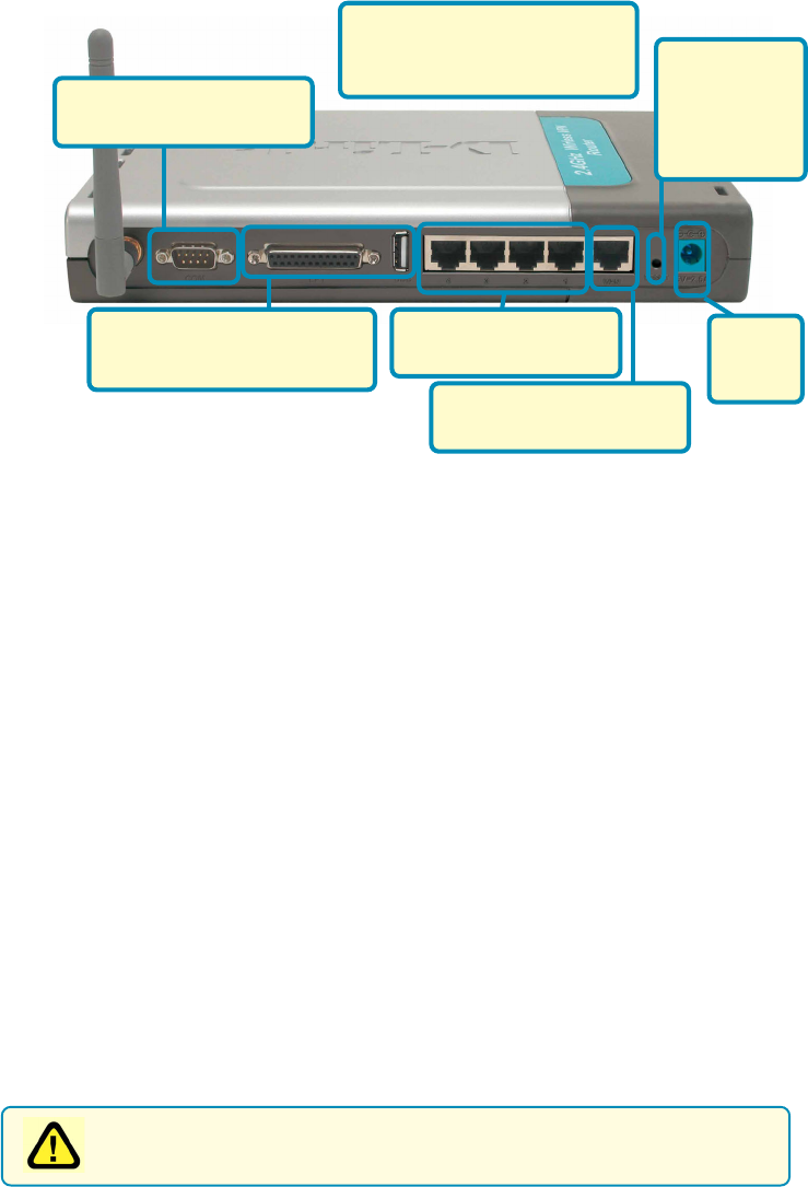
WAN and LAN ports auto detect cable types (straight-through or cross-over)
UPnP supported
LAN ports provide
connections to Ethernet-
enabled devices.
Pressing the
Reset Button
restores the
router to its
original factory
default settings.
All ports (both LAN and WAN)
auto-sense cable types to
accomodate straight-through or
cross-over cable.
Receptor
for the
Power
Adapter.
WAN port is the connection
for the Ethernet cable to the
Cable or DSL modem.
COM port is the connection
to another COM port or back-
up dial-up modem.
The LPT port or USB port is
used to connect to your local
printer.

6
LEDS
LED stands for Light-Emitting Diode. The DI-824VUP has the following LEDs
as described below:
LED LED Activity
Power A steady light indicates
a connection to a power source
WAN
A solid light indicates connection on the
WAN port. This LED blinks during data
transmission
WLAN
A blinking light indicates that the wireless
segment is ready. This LED blinks during
wireless data transmission.
D-Link AirPlus wireless products are based on industry standards to provide easy-to-
use and compatible high-speed wireless connectivity within your home, business, or
public access wireless networks. Strictly adhering to the IEEE standard, the D-Link
AirPlus wireless family of products will allow you to securely access the data you want,
when and where you want it. You will be able to enjoy the freedom that wireless networking
delivers.
A wireless local area network (WLAN) is a cellular computer network that transmits and
receives data with radio signals instead of wires. Wireless LANs are used increasingly
in both home and office environments, and public areas such as airports, coffee shops,
and universities. Innovative ways to utilize WLAN technology are helping people to work
and communicate more efficiently. Increased mobility and the absence of cabling and
other fixed infrastructure have proven to be beneficial for many users.
Wireless Basics
Flashes once per second to indicate the
unit is working properly
LOCAL
NETWORK
(Ports 1-4)
A solid light indicates a connection to an
Ethernet-enabled computer on ports 1-4. This
LED blinks during data transmission.
Status
USB
COM
A steady light indicates a connection to a USB
device
A steady light indicates a connection to COM
port or back-up dial-up modem
LPT A steady light indicates a connection to a
parallel printer port
7
Wireless Basics
Wireless users can use the same applications they use on a wired network.
Wireless adapter cards used on laptop and desktop systems support the same
protocols as Ethernet adapter cards.
Under many circumstances, it may be desirable for mobile network devices to
link to a conventional Ethernet LAN in order to use servers, printers, or an Internet
connection supplied through the wired LAN. A Wireless Router is a device used
to provide this link.
People use wireless LAN technology for many different purposes:
Mobility - Productivity increases when people have access to data in any
location within the operating range of the WLAN. Management decisions based
on real-time information can significantly improve worker efficiency.
Low Implementation Costs – WLANs (Wireless Local Area Networks) are
easy to set up, manage, change, and relocate. Networks that frequently change,
both physically and logically, can benefit from WLANs ease of implementation.
WLANs can operate in locations where installation of wiring may be impractical.
Installation Speed and Simplicity - Installing a wireless LAN system can
be fast, easy, and can eliminate the need to pull cable through walls and ceilings.
Network Expansion - Wireless technology allows the network to go where
wires cannot.
Scalability – Wireless Local Area Networks (WLANs) can be configured in a
variety of topologies to meet the needs of specific applications or existing
infrastructure. Configurations are easily changed and range from peer-to-peer
networks suitable for a small number of users to larger infrastructure networks
to accommodate hundreds or thousands of users, depending on the number
of wireless devices deployed.
8
Wireless Basics
The DI-824VUP is compatible with other D-Link AirPlus Xtreme G 802.11g
products, which include:
♦Enhanced 2.4GHz Wireless Cardbus Adapters used with laptop
computers (DWL-G650)
♦Enhanced 2.4GHz Wireless PCI cards used with desktop computers
(DWL-G520)
Installation Considerations
The D-Link AirPlus Xtreme G+ DI-824VUP lets you access your network, using
a wireless connection, from virtually anywhere. Keep in mind, however, that
the number, thickness, and location of walls, ceilings, or other objects that the
wireless signals must pass through may limit the range. Typical ranges vary
depending on the types of materials and background RF (radio frequency) noise
in your home or business. The key to maximizing wireless range is to follow
these basic guidelines:
1. Keep the number of walls and ceilings between the DI-824VUP and
your receiving device (e.g., the DWL-G650) to a minimum-each wall or
ceiling can reduce your D-Link AirPlus wireless product’s range from 3-90
feet (1-30 meters.) Position your receiving devices so that the number of
walls or ceilings is minimized.
2. Be aware of the direct line between routers and computers. A wall that is
1.5 feet thick (.5 meters), at a 45-degree angle appears to be almost 3 feet
(1 meter) thick. At a 2-degree angle it looks over 42 feet (14 meters) thick!
Try to make sure that devices are positioned so that the signal will travel
straight through a wall or ceiling for better reception.
3. Building Materials make a difference - a solid metal door or aluminum
studs may have a negative effect on range. Try to position wireless
devices and computers with wireless adapters so that the signal passes
through drywall or open doorways and not other materials.
4. Keep your product away (at least 3-6 feet or 1-2 meters) from electrical
devices or appliances that generate RF noise.
Based on the IEEE 802.11g standard, the DI-824VUP is interoperable with
existing compatible 2.4GHz wireless technology with data transfer speeds of
up to 54Mbps (with the D-Link AirPlus family of wireless devices,) as well as
standard 802.11b technology ( the D-Link Air family of wireless devices), with
speeds of up to 11Mbps.
Standards-Based Technology

9
With a single IP Address from your Broadband Internet Service provider you
can share the Internet with all the computers on your local network, without
sacrificing speed or security, using D-Link Air networking products.
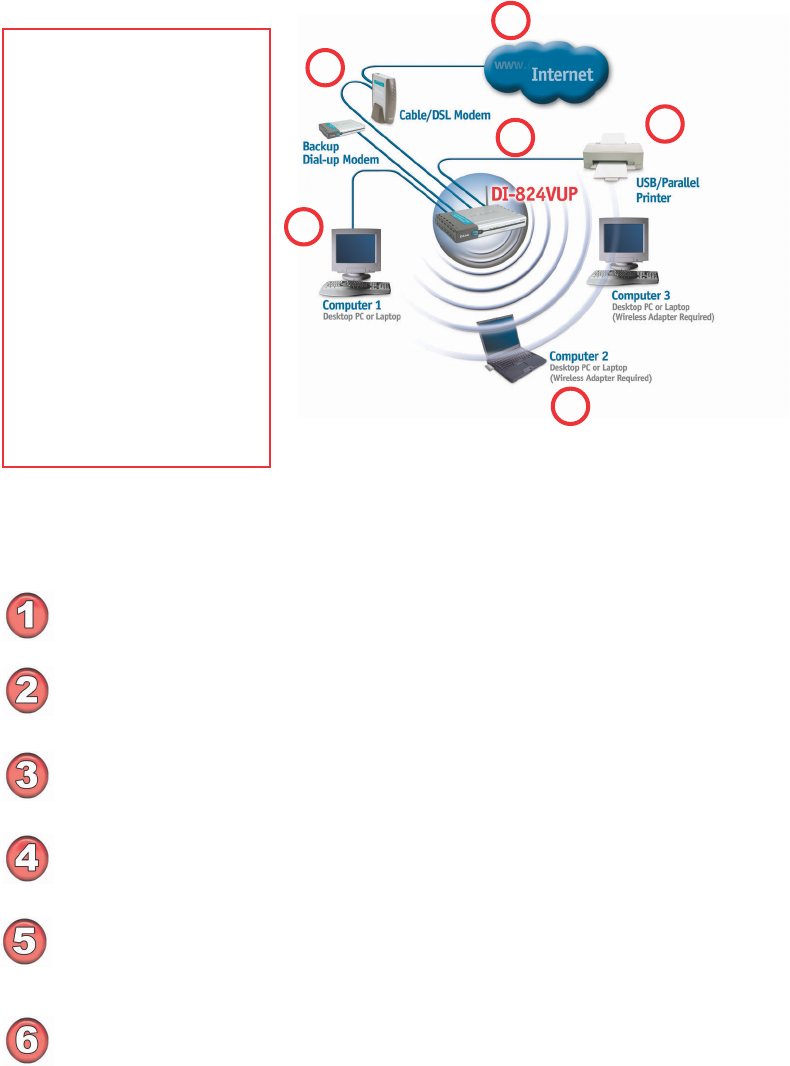
Getting Started
An Infrastructure wireless network contains an Access Point. The
Infrastructure Network example, shown here, contains the following D-Link
network devices:
A wireless Broadband Router -
D-Link AirPlus Xtreme G DI-824VUP
A laptop computer with a wireless adapter -
D-Link AirPlus Xtreme G DWL-G650
A desktop computer with a wireless adapter -
D-Link AirPlus Xtreme G DWL-G520
A Cable modem -
D-Link DCM-201
If you need to assign IP Addresses to the computers on the network, please
remember that the IP Address for each computer must be in the same
IP Address range as all the computers in the network, and the Subnet
Mask must be exactly the same for all the computers in the network.
For example: If the first computer is assigned an IP Address of 192.168.0.2
with a Subnet Mask of 255.255.255.0, then the second computer can be
assigned an IP Address of 192.168.0.3 with a Subnet Mask of 255.255.255.0,
etc.
IMPORTANT: If computers or other devices are assigned the same IP
Address, one or more of the devices may not function properly on
the network.
IP ADDRESS
With its default settings, the DI-824VUP will connect with other
D-Link Air or AirPlus products, right out of the box.
Note: If you are using a DHCP-capable router in your network setup, such
as the DI-824VUP, you will not need to assign a static IP Address.
10
Please remember that D-Link AirPlus wireless devices are pre-configured to connect
together, right out of the box, with their default settings.
Getting Started
Please refer to the following
sections of this manual for
additional information about
setting up a network:
Networking Basics - learn
how to check and assign
your IP Address; share
printers and files.
Using the Configuration
Menu - learn the settings for
the DI-824VUP, using the
web-based interface.
Troubleshooting - learn
how to check for common
installation issues and other
tips for troubleshooting.
For a typical wireless setup at home (as shown above), please do the
following:
You will need broadband Internet access (a Cable or DSL subscription line into
your home or office).
Consult with your Cable or DSL provider for proper installation of the modem.
Connect the Cable or DSL modem to the DI-824VUP wireless broadband router
(See the Quick Installation Guide included with the DI-824VUP.)
If you are connecting a desktop computer to your network, you can install the
D-Link AirPlus Xtreme G DWL-G520 wireless PCI adapter into an available PCI
slot. (See the Quick Installation Guide included with the DWL-G520.)
If you are connecting a laptop computer to your network, install the drivers for
the wireless cardbus adapter (e.g., D-Link AirPlus Xtreme G DWL-G650) into a
laptop computer.(See the Quick Installation Guide included with the DWL-
G650.)
Connect your printer to the printer port on the DI-824VUP. Please refer to
the quick installation guide for loading the print server software.
4
5
6
3
1
2
11
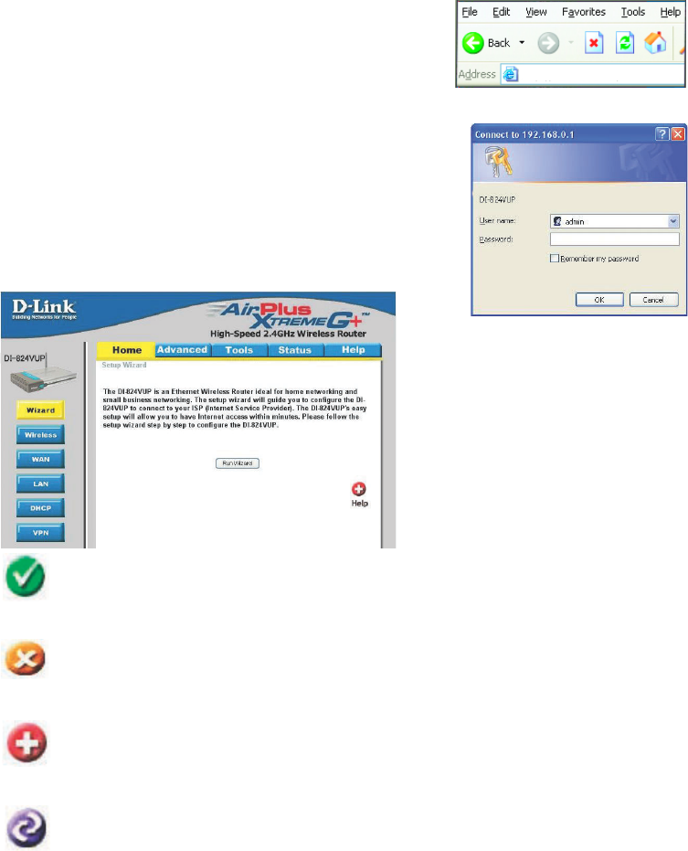
Using the Configuration Menu
Whenever you want to configure your network or the DI-824VUP, you can access the
Configuration Menu by opening the web-browser and typing in the IP Address of the
DI-824VUP. The DI-824VUP default IP Address is shown below:
Open the web browser
Type in the IP Address of
the DI-824VUP
Home > Wizard
The Home>Wizard screen will
appear. Please refer to the
Quick Installation Guide for
more information regarding the
Setup Wizard.
http://192.168.0.1
Note: if you have changed the default IP Address assigned to the DI-824VUP, make sure
to enter the correct IP Address.
The factory default User name is admin and the default
Password is blank (empty). It is recommended that you
change the admin password for security purposes. Please
refer to Tools > Admin to change the admin password.
Clicking Apply will save changes made to the page.
Apply
Clicking Cancel will clear changes made to the page.
Clicking Help will bring up helpful information regarding the page.
Help
Clicking Restart will restart the router. (Necessary for some changes.)
Cancel
Restart
12
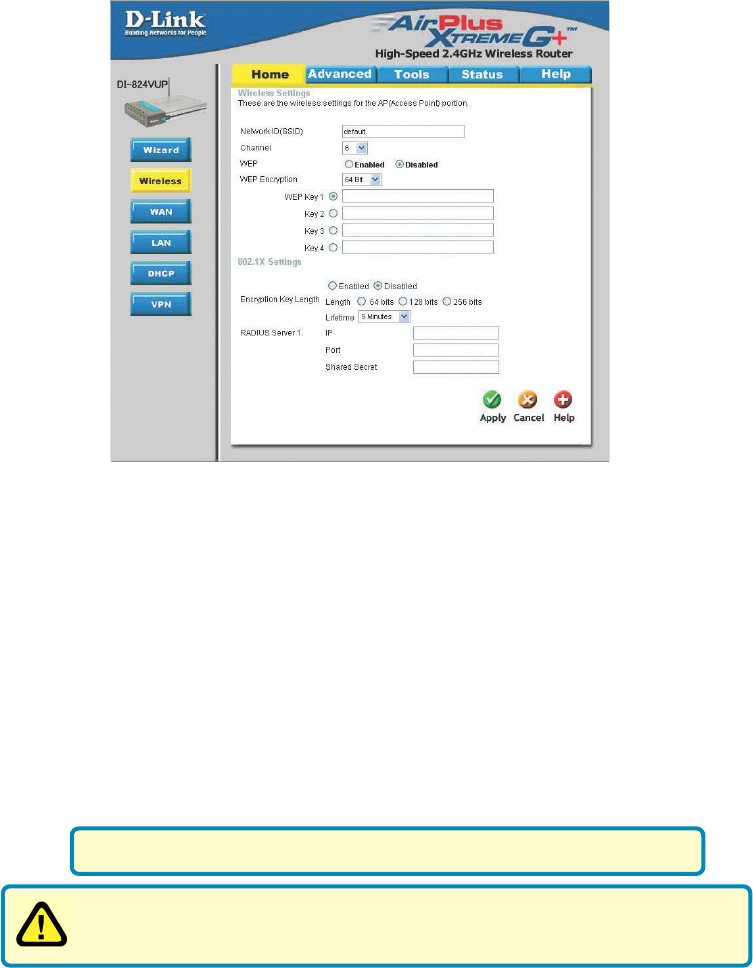
Home > Wireless
Using the Configuration Menu
SSID
Channel
default is the default setting. All devices on the network must
share the same SSID. If you change the default setting, the
SSID may be up to 32 characters long.
6 is the default channel. All devices on the network must share
the same channel.
WEP Encryption Select the level of encryption desired: 64, 128, or 256-bit.
Requires 10 digits
Requires 26 digits
Requires 58 digits
64-bit
128-bit
256-bit
Hexadecimal digits consist of the numbers 0-9 and the letters A-F.
WEP (Wired Equivalent Privacy) If you enable encryption on the
DI-824VUP, make sure to also enable encryption on all 802.11b wireless
clients, or wireless connection will not be established.
Input up to 4 WEP keys using Hexadecimal format; select the
one you wish to use.
Keys 1-4
WEP Click Enabled or Disabled (default).
13
Home > Wireless (Continued)
Using the Configuration Menu
802.1x
RADIUS Server Enter the IP address and port number of the RADIUS server that
will be used as the 802.1x authenticator. Enter the secret key that
has also been entered into the RADIUS server’s configuration.
Encryption Key
The 802.1x is an authentication method which is designed to
compliment the existing WEP encryption. During the authentication
process, the server verifies the identity of the client attempting to
connect to the network. With the proper client account and encryption
key, access to the network is granted. Unfamiliar encryption key or
clients are denied from accessing the wireless network. This feature
will help safe guard a Local Area Network (LAN) from unwanted
visitors.
To take the full advantage of the 802.1x in DI-824VUP, all of the
wireless devices on your network must be 802.1x compatible and
must have the 802.11x feature enabled to communicate with the
router. (Note: Windows 2000 users will find a few downloads to
enable 802.1x clients on the Microsoft website.)
Selection for Encryption Key
- 64 bits – This will generate a 10 digit Dynamic Key value for
encryption.
- 128 bits – This will generate a 26 digit Dynamic Key value for
encryption.
- 256bits – This will generate a 58 digit Dynamic Key value for
encryption.
- Lifetime – Select the period of time before a new Dynamic Key
is generated.
* Dynamic Keying is a
technique for changing
the WEP Key used
between the supplicant
(wireless client) and the
access point.
14
Using the Configuration Menu
Home > WAN
Choose WAN Type
WAN stands for Wide Area Network. In this case WAN represents the mode in which
your ISP connects to the Internet. If you are uncertain, please ask your ISP which of the
following represents your connection mode to the Internet:
Static IP Address Your ISP assigns you a Static IP Address.
Dynamic
IP Address
Obtain an IP address from your ISP automatically (mainly for
Cable users).
Others
For use in Europe only.
For use in Australia only.
PPTP
Big Pond Cable
PPP over Ethernet Some ISPs require the use of PPPoE to connect to their
services (mainly for DSL users).
Dial-up Network Dial-up users can select this option to connect to their ISP
through an analog dial-up modem if broadband connectivity
is unavailable.

15
Using the Configuration Menu
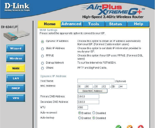
Home > WAN > Dynamic IP Address
Most Cable modem users will select this option to obtain an IP
Address automatically
from their ISP (Internet Service Provider).
Host Name This is optional, but may be required by some ISPs. The host
name is the device name of the Router.
MAC Address The default MAC Address is set to the WAN’s physical inter-
face MAC address on the Router.
Clone
MAC Address
This feature will copy the MAC address of the Ethernet card,
and replace the WAN MAC address of the Router with this
Ethernet card MAC address. It is not recommended that you
change the default MAC address unless required by your ISP.
Renew IP Forever Enable this feature to allow the router to automatically recon-
nect to the ISP if the connection drops.
16
Using the Configuration Menu
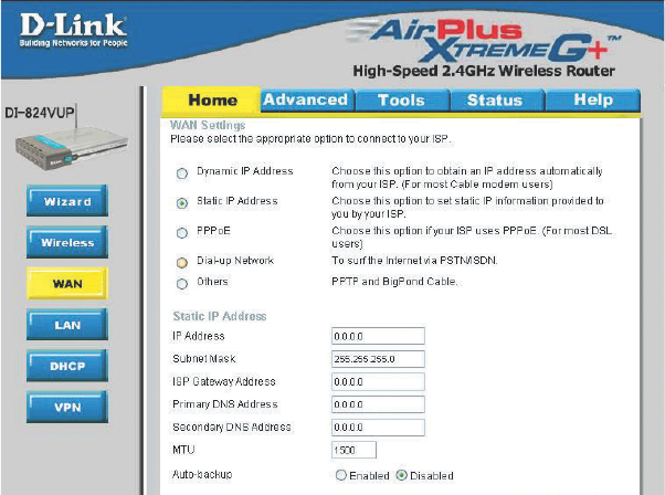
Home > WAN > Static IP Address
If you use a Static IP Address, you will input information here that your ISP has provided
to you.
Secondary DNS (Optional) Input the Secondary DNS address provided by your
ISP.
Primary DNS Input the primary DNS address provided by your ISP.
WAN Gateway Input the Gateway address provided by your ISP.
WAN Subnet Mask Input the Subnet Mask provided by your ISP.
WAN IP Address Input the IP Address provided by your ISP.
MTU Maximum Transmission Unit; default is 1500; you may need to
change the MTU to conform to your ISP.
Auto-backup Enabling this feature will connect your router to the Internet us-
ing a dial-up service if your broadband connection becomes un-
available. A subscription to a dial-up service is required for the
auto-backup to work.
17
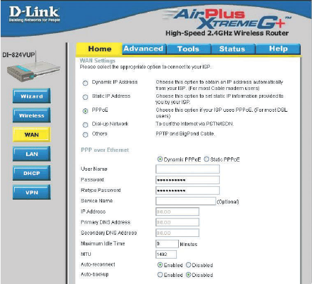
Using the Configuration Menu
Home > WAN > PPPoE
Most DSL users will
select this option to
obtain an IP address
automatically from
their ISP through the
use of PPPoE.
MTU Maximum Transmission Unit; default is 1492; you may need to
change the MTU to conform to your ISP.
IP Address (Optional) Enter in the IP Address if you are assigned a static
PPPoE address.
Service Name (Optional) Check with your ISP for more information if they
require the use of service name.
Maximum
Idle Time
Enter a maximum idle time during which Internet connection is
maintained during inactivity. To disable this feature, enable Auto-
reconnect.
Secondary DNS (Optional) Input the secondary DNS address.
Primary DNS You will get the DNS IP automatically from your ISP but you
may enter a specific DNS address that you want to use instead.
Password
Your PPPoE username provided by your ISP.
User Name
Your PPPoE password provided by your ISP.
Auto-reconnect If enabled, the Broadband Router will automatically connect to
your ISP after your system is restarted or if the connection is
dropped.
Auto-backup Enabling this feature will connect your router to the Internet us-
ing a dial-up service if your broadband connection becomes un-
available. A subscription to a dial-up service is required for the
auto-backup to work.
18
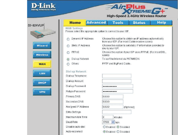
Using the Configuration Menu
Home > WAN > Dial-up Network
Most Dial-up users will
select this option to con-
nect to their ISP through
an analog dial-up modem.
This feature can be used
as a back-up when your
broadband connectivity is
unavailable.
Extra Settings
Assigned
IP Address
(Optional) Enter in the IP Address if you are assigned a static
PPPoE address.
Primary DNS/
Seconday DNS
If the settings are configured as “0.0.0.0,” they will be auto-
matically assigned upon connection.
Baud Rate
Maximum Idle Time Enter a maximum idle time during which Internet connection
is maintained during inactivity. To disable this feature, en-
able Auto-reconnect.
Dial-up Password Password provided by your ISP
Dial-up Account
Telephone number to connect to your ISP
Dial-up Telephone
Username provided by your ISP
The communication speed between the DI-824VUP and your
modem.
This setting is used to optimize the communication quality
between the ISP and your analog dial-up modem. (Initializa-
tion string) - optional.
Auto-reconnect If enabled, the Broadband Router will automatically connect
to your ISP after your system is restarted or if the connection
is dropped.
19
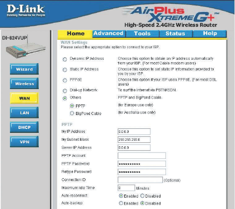
Using the Configuration Menu
Home > WAN > Others > PPTP
PPTP Password Enter the PPTP password.
PPTP Account Enter the PPTP account name.
My Subnet Mask Enter the Subnet Mask.
Connection ID (Optional) Enter the connection ID if required by your ISP.
Maximum
Idle Time
Enter a maximum idle time during which Internet connection is
maintained during inactivity. To disable this feature, enable Auto-
reconnect.
My IP Address Enter the IP Address.
Server IP Address Enter the Server IP Address.
Point-to-Point Tunneling Protocol (PPTP) is a WAN connection used in Europe.
Auto-reconnect If enabled, the Broadband Router will automatically connect to
your ISP after your system is restarted or if the connection is
dropped.
Auto-backup Enabling this feature will connect your router to the Internet
using a dial-up service if your broadband connection becomes
unavailable. A subscription to a dial-up service is required for
the auto-backup to work.
20
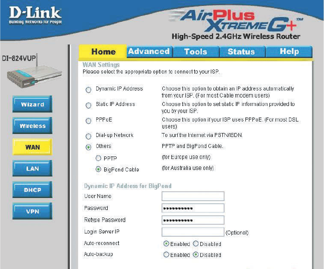
Using the Configuration Menu
Home > WAN > Others > BigPond Cable
User Name Enter in the user name for the BigPond account.
Password Enter the password for the BigPond account.
Login Server IP (Optional) Enter the Login Server IP if required.
Dynamic IP Address for BigPond is a WAN connection used in Australia.
Auto-reconnect If enabled, the Broadband Router will automatically connect to
your ISP after your system is restarted or if the connection is
dropped.
Auto-backup Enabling this feature will connect your router to the Internet us-
ing a dial-up service if your broadband connection becomes un-
available. A subscription to a dial-up service is required for the
auto-backup to work.
21
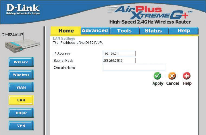
Home > LAN
Using the Configuration Menu
LAN is short for Local Area Network. This is considered your internal network. These are
the IP settings of the LAN interface for the DI-824VUP. These settings may be referred to
as Private settings. You may change the LAN IP address if needed. The LAN IP address
is private to your internal network and cannot be seen on the Internet.
Domain Name (Optional) The name of your local domain.
Subnet Mask The subnet mask of the LAN interface.
The default subnet mask is 255.255.255.0.
IP Address The IP address of the LAN interface.
The default IP address is: 192.168.0.1.
22
Using the Configuration Menu
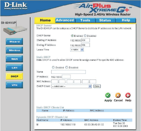
Home > DHCP
DHCP stands for Dynamic Host Control Protocol. The DI-824VUP has a built-in DHCP
server. The DHCP Server will automatically assign an IP address to the computers on
the LAN/private network. Be sure to set your computers to be DHCP clients by setting
their TCP/IP settings to “Obtain an IP Address Automatically.” When you turn your
computers on, they will automatically load the proper TCP/IP settings provided by the
DI-824VUP. The DHCP Server will automatically allocate an unused IP address from the
IP address pool to the requesting computer. You must specify the starting and ending
address of the IP address pool.
Lease Time The length of time for the DHCP lease.
DHCP Clients List Lists the DHCP clients connected to the DI-824VUP. Click Re-
fresh to update the list. The table will show the Host Name, IP
Address, and MAC Address of the DHCP client computer.
Enable or disable the DHCP service.
DHCP Server
Ending IP Address The ending IP address for the DHCP server’s IP assignment.
Starting IP Address The starting IP address for the DHCP server’s IP assignment.
Static DHCP Used to allow the DHCP server to assign the same IP adress to
a specific MAC address. Enter the name, IP address, and MAC
address into the fields. Select which DHCP client to clone.
23
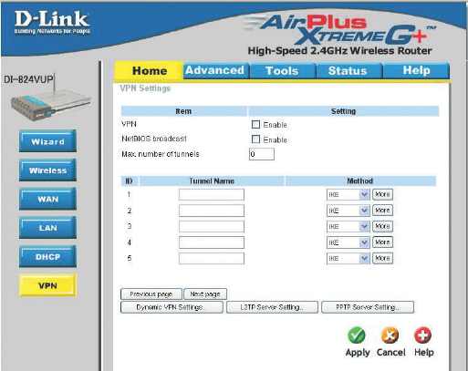
Home > VPN Settings
Using the Configuration Menu
VPN Settings are settings
that are used to create
virtual private tunnels to
remote VPN gateways. The
tunnel technology supports
data confidentiality, data
origin, authentication, and
data integrity of network
information by utilizing
encapsulation protocols,
encryption algorithms, and
hashing algorithms.
Max. number of
tunnels
Create a name for the tunnel.
NetBIOS broadcast
Click Enable to enable VPN tunnels. When you are not
using the VPN feature, it is best to keep VPN disabled.
VPN
Method IPSec VPN supports two kinds of key-obtained methods:
manual key and automatic key exchange. Manual key
approach indicates that the two endpoint VPN gateways
require setting up authentication and encryption key by
the Administrator manually. However, IKE approach will
perform automatic Internet key exchange. Admins of both
endpoint gateways will only need to set the same
pre-shared key.
For more in depth configuration to adjust manual key or IKE
method settings, click More.
More
Tunnel Name
Select the maximum number of allowable tunnels.
Enable this to allow NetBIOS braodcast over the VPN
tunnels.
24
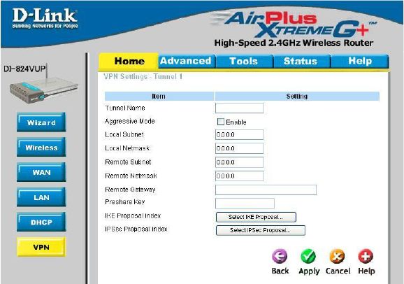
Remote Subnet The subnet of the remote VPN gateway’s local network. It
can be a host, a partial subnet, or a whole subnet.
Remote Netmask The subnet of the remote VPN gateway’s local network.
It can be a host, a partial subnet, or a whole subnet.
Remote Gateway The WAN IP address of remote VPN gateway.
Home > VPN Settings > Tunnel > Method >IKE
Using the Configuration Menu
Local Subnet The subnet of the VPN gateway’s local network. It can be a
host, a partial subnet or a whole subnet.
Local Netmask Local netmask combined with local subnet to form a subnet
domain.
Aggressive Mode Enabling this mode will accelerate establishing tunnel, but
the device will have less security.
Tunnel Name Current tunnel name.
IKE Proposal index Click the button to setup a set of frequent-used IKE proposals
and select from the set of IKE proposals for the tunnel.
IPSec Proposal
index
Click the button to setup a set of frequent-used IPSec proposals
and select from the set of IKE proposals for the tunnel.
Preshared Key The first key that supports IKE mechanism of both VPN
gateways for negotiating further security keys. The pre-
shared key must be the same for both endpoint gateways.

25
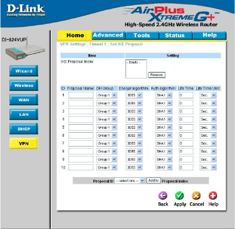
Using the Configuration Menu
Home > VPN Settings > Tunnel > Method > IKE > Select IKE Proposal
IKE Proposal index
Proposal Name
DH Group
Encrypt algorithm
Auth algorithm
A list of selected proposal indexes from the IKE proposal pool
listed below.
There are three groups that can be selected: group 1
(MODP768), group 2 (MODP1024), and group 5
(MODP1536).
There are two algorithms that can be selected: 3DES and
DES.
There are two algorithms that can be selected: SHA1 and
MD5.
This is the name used to classify the IKE proposal.
26
Using the Configuration Menu
Home > VPN Settings > Tunnel > Method > IKE > Select IKE Proposal
Continued...
Life Time Enter in the life time value.
Life Time Unit There are two units that can be selected: second and KB.
Proposal ID The identifier of IKE proposal can be chosen for adding the
corresponding proposal to the dedicated tunnel.
Add to Click it to add the chosen proposal indicated by proposal ID
to IKE Proposal index list.

27
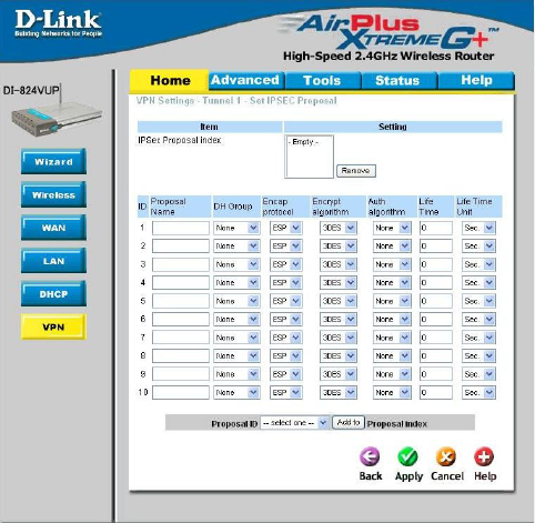
Using the Configuration Menu
Home > VPN Settings > Tunnel > Method > IKE > Select IPSEC Proposal
IPSec Proposal
index
A list of selected proposal indexes from the IPSec proposal
pool listed below.
Proposal Name
DH Group There are three groups that can be selected: group 1
(MODP768), group 2 (MODP1024), and group 5
(MODP1536).
Encap protocol There are two protocols that can be selected: ESP and AH.
Encrypt algorithm There are two algorithms that can be selected: 3DES and
DES.
This is the name used to classify the IPSec Proposal
Auth algorithm There are two algorithms that can be selected: SHA1 and
MD5.
28
Using the Configuration Menu
Home > VPN Settings > Tunnel > Method > IKE > Select IPSEC Proposal
Continued...
Life Time Enter in a life time value.
Life Time Unit There are two units that can be selected: second and KB.
Proposal ID The identifier of IPSec proposal can be chosen for adding the
corresponding proposal to the dedicated tunnel.
Add to Click it to add the chosen proposal indicated by proposal ID
to IPSec Proposal index list.