D Link TW1130 Wireless VPN Router User Manual di714P manual 1 31
D Link Corporation Wireless VPN Router di714P manual 1 31
D Link >
Contents
User Manual Part 3
53
Using the Configuration Menu
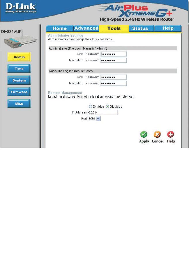
Tools > Admin
Password
Remote
Management
To change the administrator or user password, enter in the old pass-
word and enter the new password twice to confirm.
You can change the administrator and user passwords here. It is recommended that
you change the administrator password from the default setting.The default password is
blank (nothing).
Remote Management allows the device to be configured through
the WAN (Wide Area Network) port from the Internet using a web
browser. A username and password is still required to access the
browser-based management interface.
IP Address Internet IP Address of the computer that has access to the DI-824VUP.
If the IP Address is set to 0.0.0.0, this allows all Internet IP ad-
dresses to access the DI-824VUP.
Port The port number used to access the DI-824VUP.
Example:http://x.x.x.x:8080, where x.x.x.x. is the WAN IP address
of the DI-824VUP+ and 8080 is the port used for the Web Manage-
ment interface.
54
Using the Configuration Menu
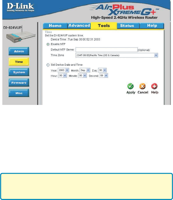
Tools > Time
Enable NTP (Network Time Protocol). Select to synchronize the time on the
DI-824VUP to an NTP server.
Set Device Date
and Time
You can manually set the time on your network here.
You will need to set the time zone corresponding to your location. The time can be
set manually or the device can connect to a NTP (Network Time Protocol) server to
retrieve the time.
NTP is short for Network Time Protocol, an Internet standard protocol
that assures accurate synchronization to the millisecond of computer
clock times in a network of computers.

55
Using the Configuration Menu
Tools > System
Click Save to save the current settings to the local Hard Drive.
Click Browse to find the settings file, then click Load.
Save Settings to
Local Hard Drive
Load Settings from
Local Hard Drive
Restore to Factory
Default Settings
Click Restore to restore the factory default settings.
The current system settings can be saved as a file onto the local hard drive. The saved
file or any other saved setting file created by the DI-824VUP can be uploaded into the
unit. To reload a system settings file, click on “Browse” to search the local hard drive for
the file to be used. The device can also be reset back to factory default settings by
clicking on “Reset to Default” button. Use the restore feature only if necessary. This will
erase previously saved settings for the unit. Make sure to save your system settings
before doing a factory restore.
56
Using the Configuration Menu
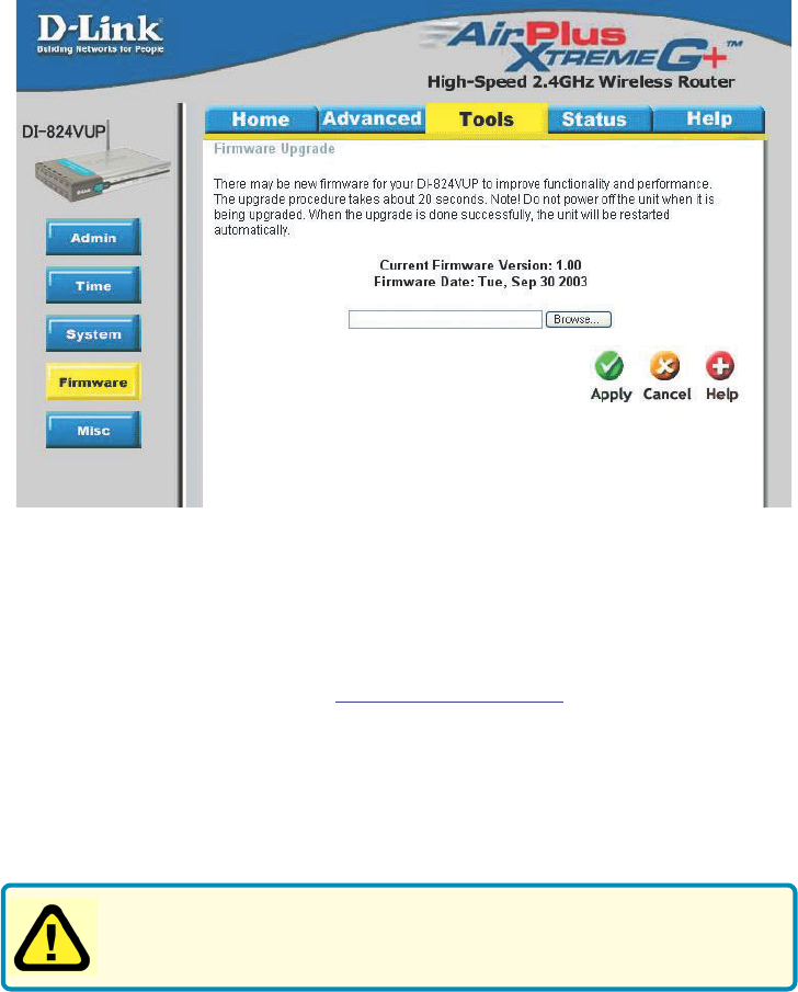
Tools > Firmware
Browse After you have downloaded the new firmware, click Browse in
this window to locate the firmware update on your hard drive.
Click Apply to complete the firmware upgrade.
Note! Do not power off the unit when it is being upgraded. When the
upgrade is complete, the unit will be restarted automatically.
You can upgrade the firmware of the device using this tool. Make sure that the firmware
you want to use is saved on the local hard drive of the computer. Click on “Browse” to
search the local hard drive for the firmware to be used for the update. Upgrading the
firmware will not change any of your system settings but it is recommended that you
save your system settings before doing a firmware upgrade. Please check the D-Link
support site for firmware updates at http://support.dlink.com.
57
Using the Configuration Menu
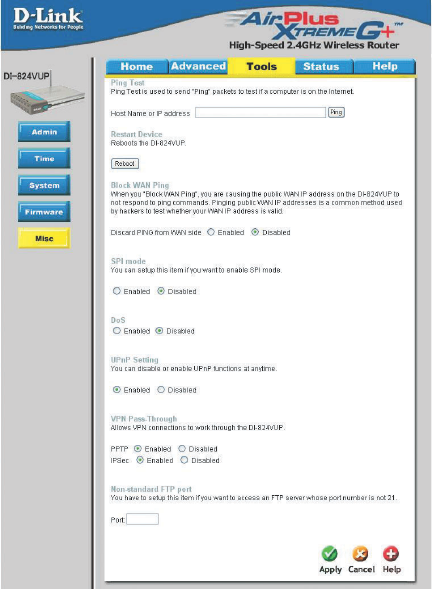
Tools > Misc
Block WAN Ping Click Enable to block the WAN ping. Computers on the Internet
will not get a reply back from the DI-824VUP when it is being
“ping”ed. This may help to increase security.
Restart Device Click Reboot to restart the unit.
Ping Test In the open box, enter in a URL (i.e., www.dlink.com) or an IP
address and click on Ping to test your internet connection.
SPI Mode When this feature is enabled, the router will record the packet
information passed through the router such as IP address, port
address, ACK, SEQ number, and so on. The router will also
check every incoming packet to detect if it is valid.
DoS When DoS is enabled, the router will prevent Denial of Service
attacks on all computers connected to the DI-824VUP.

58
Using the Configuration Menu
Tools > Misc (Continued)
Non-standard
FTP port
If an FTP server you want to access is not using the standard port
21, then enter in the port number that the FTP server is using in-
stead.
UPnP UPnP is short for Universal Plug and Play which is a networking
architecture that provides compatibility among networking equip-
ment, software, and peripherals. The DI-824VUP is a UPnP enabled
router and will only work with other UPnP devices/softwares. If you
do not want to use the UPnP Functionality, it can be disabled by
selecting “Disabled”.
VPN Pass-
Through
The device supports VPN (Virtual Private Network) pass-through for
both PPTP (Point-to-Point Tunneling Protocol) and IPSec (IP Secu-
rity). Once VPN pass-through is enabled, there is no need to open
up virtual services. Multiple VPN connections can be made through
the device. This is useful when you have many VPN clients on the
LAN.
59
Using the Configuration Menu
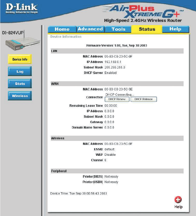
Status > Device Info
This screen displays information about the DI-824VUP such as WAN, LAN, and Wire-
less status.
DHCP Renew Use this button to reconnect to your ISP, if your WAN connection is
set up for DHCP.
DHCP Release Use this button to disconnect from your ISP, if your WAN connection
is set up for DHCP.
60
Using the Configuration Menu
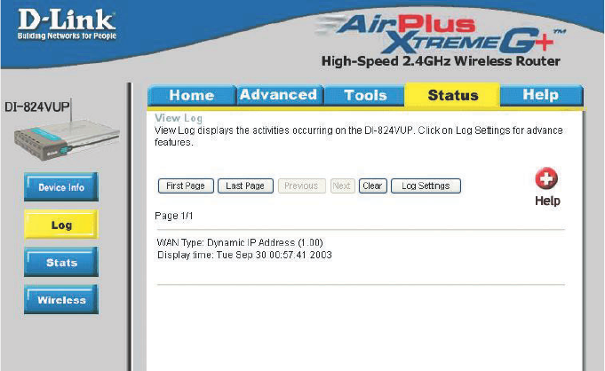
Status > Log
This screen displays activities occurring on the DI-824VUP.
Log Settings Click for advanced features (see next page).
First Page Click First Page to go to the first page of the log.
Last Page Click Last Page to go to the last page of the log.
Previous Click Previous to go to the previous page of the log.
Next Click Next to go to the next page of the log.
Clear Click Clear to clear the current page of the log.
61
Using the Configuration Menu
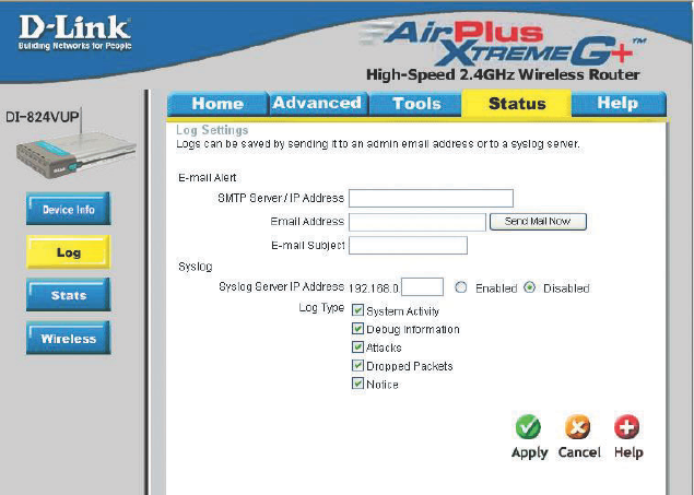
Status > Log > Log Settings
Email Address Enter in the email address of the recipient who will receive the
email log.
Enter in the IP address of a syslog server within the network.
Click Enable to activate the policy. The DI-824VUP will send
all of it’s logs to the specified syslog server.
IP Address of the
Syslog Server
E-Mail Alert The DI-824VUP can be set up to send the log files to a specific
email address.
SMTP Server IP Enter in the IP address of the mail server.
Send Mail Now Click to send mail immediately.
Log Type Select the types of activity to log. By default, all values are
selected.
62
Using the Configuration Menu
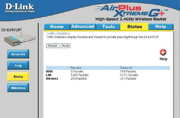
Status > Stats
In the Stats section, traffic statistics are displayed.
Refresh This will update the page.
Reset This will reset the packet counter to zero.
WAN Displays Received / Transmitted packets from the WAN port.
LAN Displays Received / Transmitted packets from the LAN port.
63
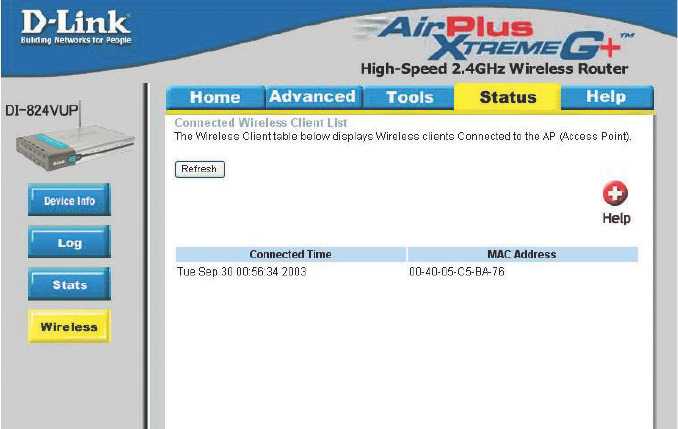
This screen displays the connection time and the MAC Address of the connected
wireless clients. Click on Refresh for the most recent information.
Using the Configuration Menu
Status > Wireless
64
Using the Configuration Menu
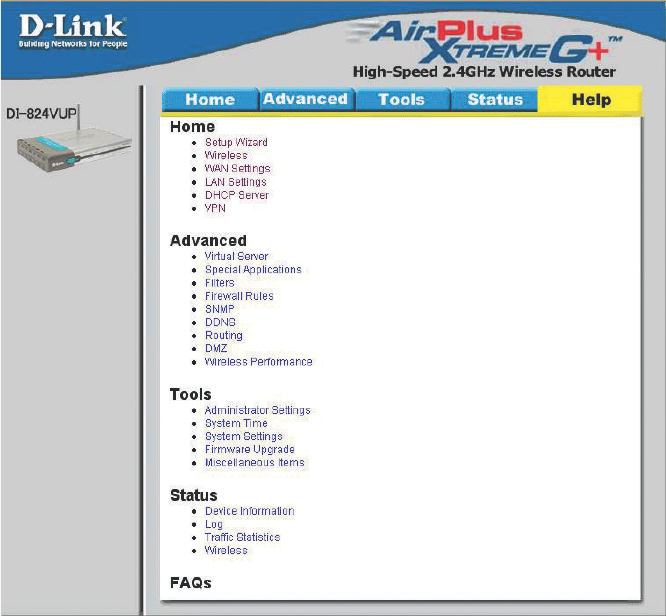
Help
This screen displays the complete Help menu. For help at anytime, click the Help tab in
the Configuration menu.
65
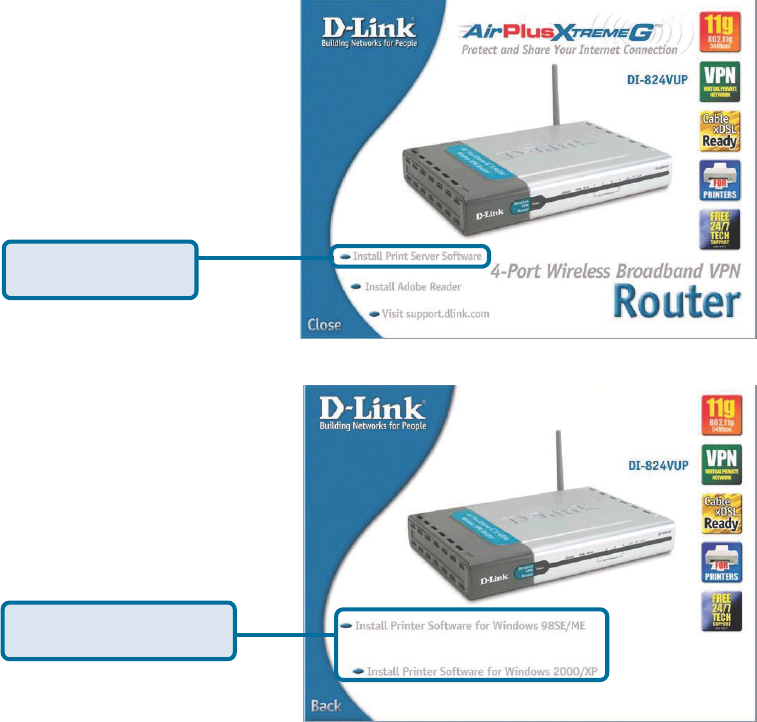
Insert the installation CD-ROM into the CD-ROM drive. The following window will be
shown automatically. If it is not, please run “autorun.exe” on the CD-ROM.
Installing the Print Server Software
Click Install Print
Server Software
Select your Windows
operating system
66
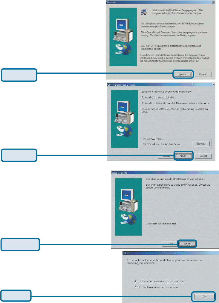
Wait until the following Welcome
dialog appears.
Select the destination folder.
Click Next
After rebooting your computer, the software installation procedure is finished.
Installing the Print Server Software (continued)
Click OK
Then, the setup program will begin
to install the programs into the
destination folder.
When the following window is
displayed.
Click Finish
Click Next
67
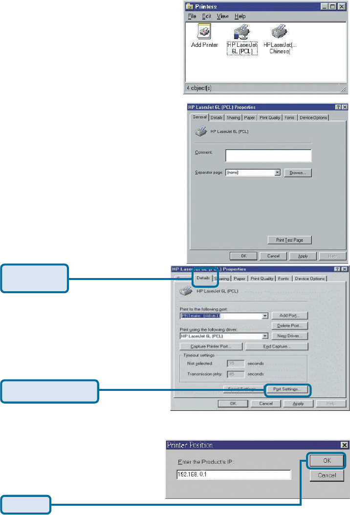
Configuring on Windows 98se/Me Platforms
After you finish the software installation pro-
cedure, your computer will be capable of
network printing provided by the DI-
824VUP. For convenience, we call the
printer connected to the printer port of the
DI-824VUP a printer server. On a Windows
95/98 platform, open the Printers window
in the My Computer menu.
Now, you can configure the print server of
the DI-824VUP:
Find out the corresponding icon of your
printer server, for example, the HP
LaserJet 6L. Right click on that icon, and
then select Properties.
The following screen appears:
Choose the “PRTmate: (All-in-1)” from
the list attached at the Print To item.
Be sure that the Printer Driver item
is configured to the correct driver of
your printer server.
Type in the IP address of the
DI-824VUP.
Click on the
Details tab
Click Port Settings
Click OK
68
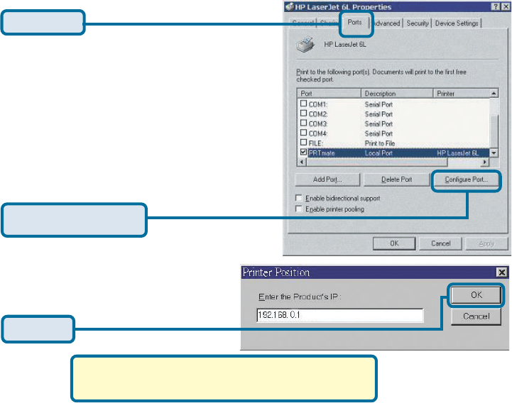
Configuring on Windows 2000/XP Platforms
The configuration procedure for a
Windows 2000/XP platform is similar to
that of Windows 95/98 except the
screen of printer Properties.
(Note: Screen shots are taken in Windows 2000,
similar screens will appear in Windows XP.)
Click Port
Click Configure Port
Type in the IP address of the
DI-824VUP.
Click OK
69
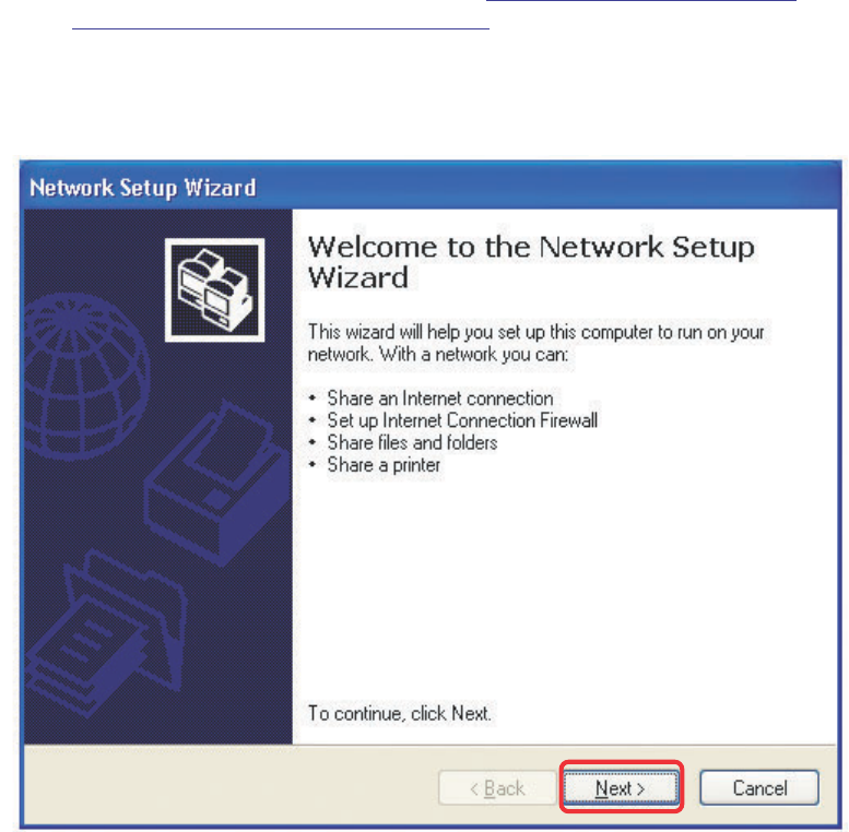
Using the Network Setup Wizard in Windows XP
In this section you will learn how to establish a network at home or work,
using Microsoft Windows XP.
Note: Please refer to websites such as http://www.homenethelp.com
and http://www.microsoft.com/windows2000 for information about networking
computers using Windows 2000, ME or 98.
Go to Start > Control Panel > Network Connections
Select Set up a home or small office network
Networking Basics
When this screen appears, Click Next.
70
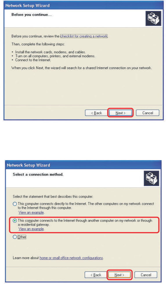
Please follow all the instructions in this window:
Networking Basics
Click Next.
In the following window, select the best description of your computer. If your
computer connects to the internet through a gateway/router, select the
second option as shown.
Click Next.
71
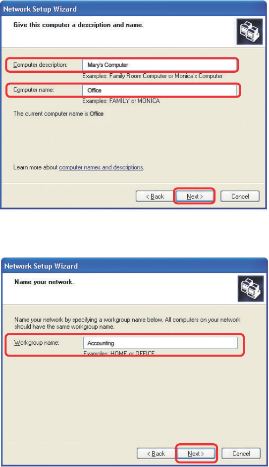
Enter a Computer description and a Computer name (optional).
Networking Basics
Click Next.
Enter a Workgroup name. All computers on your network should have the
same Workgroup name.
Click Next.
72
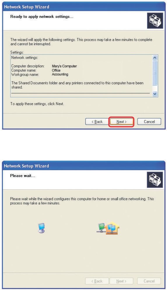
Please wait while the Network Setup Wizard applies the changes.
Networking Basics
When the changes are complete, click Next.
Please wait while the Network Setup Wizard configures the computer.
This may take a few minutes.
73
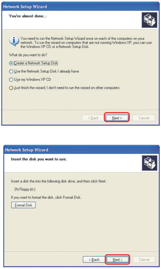
Networking Basics
In the window below, select the option that fits your needs. In this example, Create a
Network Setup Disk has been selected. You will run this disk on each of the
computers on your network. Click Next.
Insert a disk into the Floppy Disk Drive, in this case drive A.
74
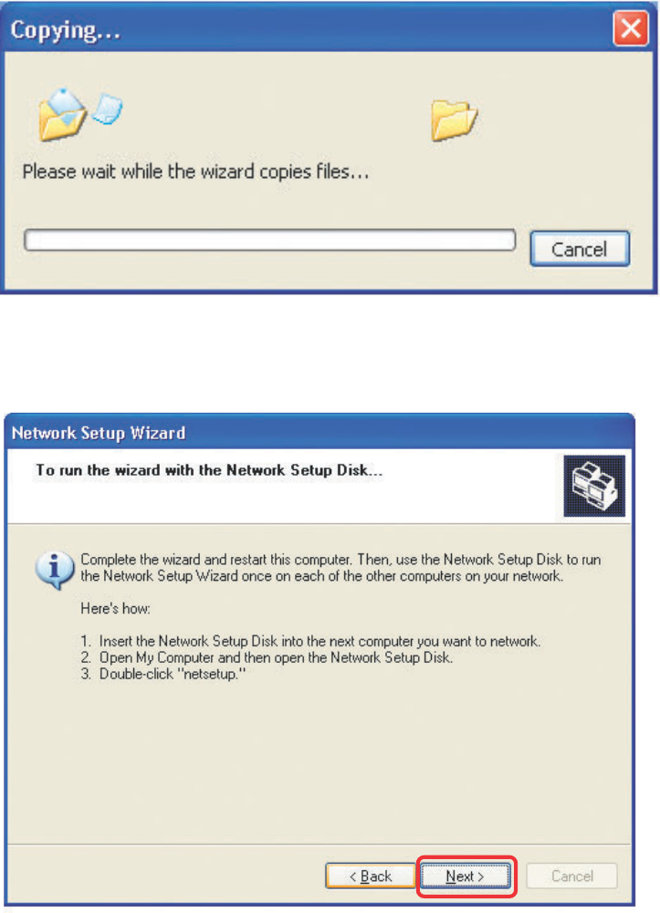
Networking Basics
Please read the information under Here’s how in the screen below. After you complete
the Network Setup Wizard you will use the Network Setup Disk to run the Network
Setup Wizard once on each of the computers on your network. To continue click Next.
75
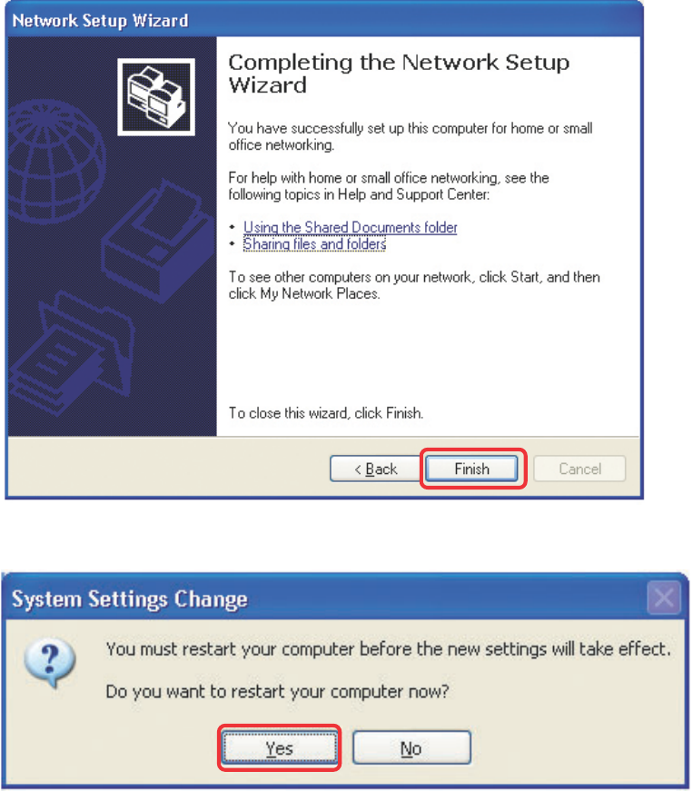
Networking Basics
Please read the information on this screen, then click Finish to complete the
Network Setup Wizard.
The new settings will take effect when you restart the computer. Click Yes to
restart the computer.
You have completed configuring this computer. Next, you will need to run the
Network Setup Disk on all the other computers on your network. After running
the Network Setup Disk on all your computers, your new wireless network
will be ready to use.