D Link TW1130 Wireless VPN Router User Manual di714P manual 1 31
D Link Corporation Wireless VPN Router di714P manual 1 31
D Link >
Contents
User Manual Part 7
127
How can I set up my DI-824VUP to work with a DFL-300 Firewall?
(continued)
Frequently Asked Questions (continued)
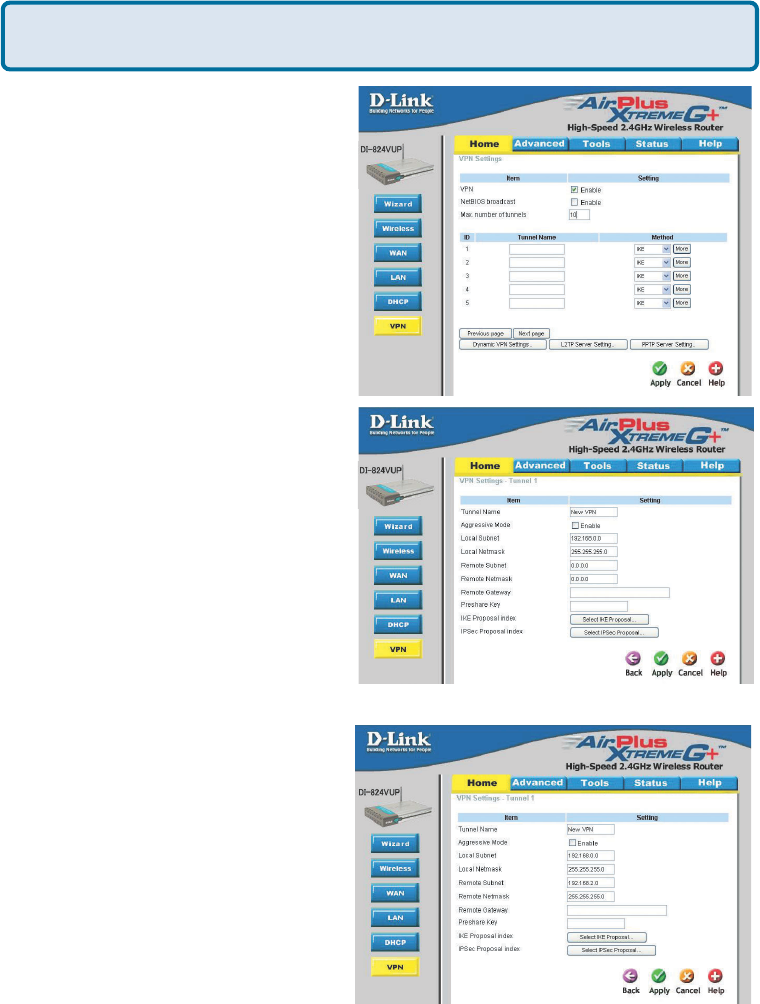
Step 3 In the space provided, enter the
Tunnel Name for ID number 1, select IKE,
and then click More.
Step 4 In the Local Subnet and Local
Netmask fields enter the network
identifier for DI-824VUP´s LAN and the
corresponding subnet mask.
Step 5 In the Remote Subnet and
Remote Netmask fields enter the
network identifier for the DFL-300´s
Internal interface and the corresponding
subnet mask.
128
How can I set up my DI-824VUP to work with a DFL-300 Firewall?
(continued)
Frequently Asked Questions (continued)
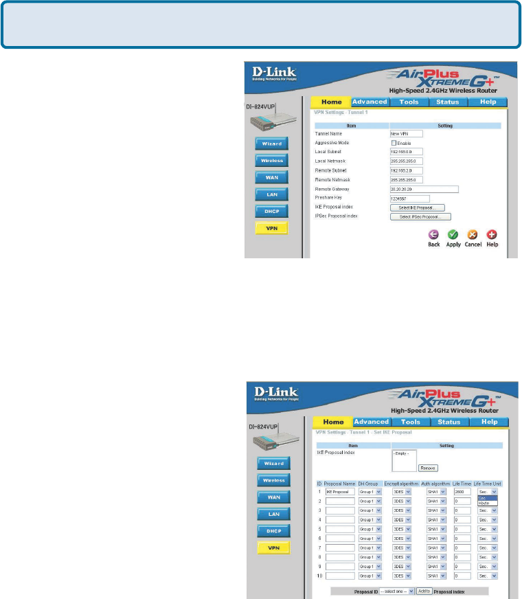
Step 6 In the Remote Gateway field
enter the WAN IP address of the remote
DFL-300 and in the Preshared Key field,
enter a key which must be exactly the
same as the Preshared Key that is
configured on the DFL-300.
Step 7 Click Apply. The device will
restart. Click on the Continue button and
then click on Select IKE Proposal.
Step 8 Enter a name for proposal ID number 1 and select Group 2 from the DH Group
dropdown menu.
Step 9 Select 3DES as the Encryption Algorithm and SHA-1 as the Authentication
Algorithm.
Step 10 Enter a Lifetime value of 28800
and then select Sec. as the unit for the
lifetime value.
129
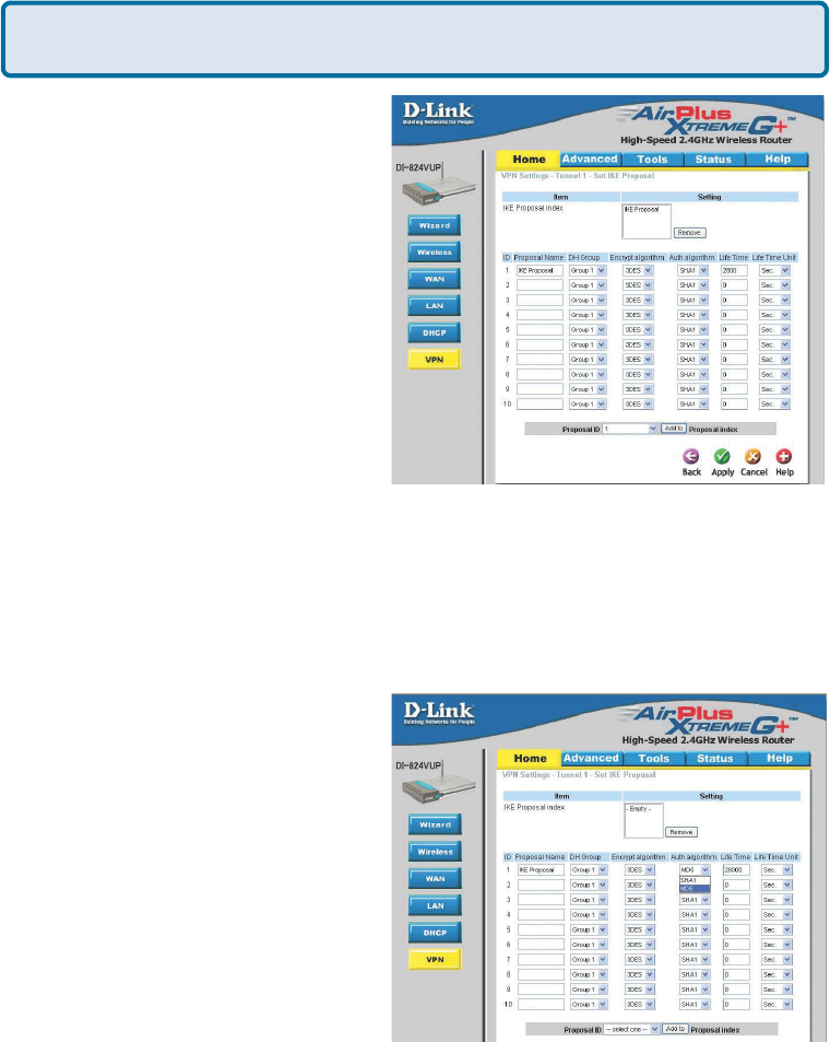
Step 11 Select 1 out of the Proposal
ID dropdown menu and click Add To,
which will add the proposal that was just
configured to the IKE Proposal Index.
Click Apply. The device will restart. Click
on the Continue button and then click
Back.
How can I set up my DI-824VUP to work with a DFL-300 Firewall?
(continued)
Frequently Asked Questions (continued)
Step 12 Click on Select IPSec
Proposal.
Step 13 Enter a name for proposal ID
number 1 and select None from the DH
Group dropdown menu.
Step 14 Select ESP as the Encapsulation Protocol.
Step 15 Select 3DES as the Encryption Algorithm and MD5 as the Authentication
Algorithm.
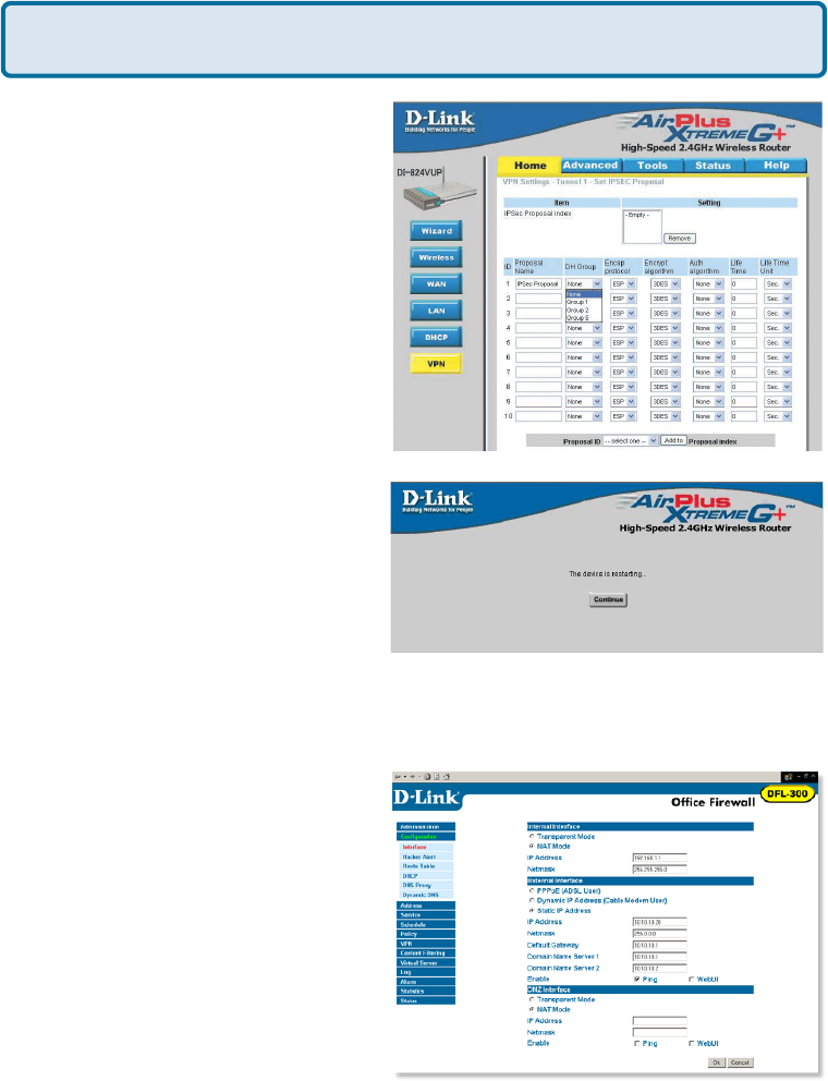
Step 16 Enter a Lifetime value of 28800
and then select Sec. as the unit for the
lifetime value.
130
Step 17 Select 1 out of the Proposal
ID dropdown menu and click Add To,
which will add the proposal that was just
configured to the IPSec Proposal Index.
Click Apply and then click Restart.
How can I set up my DI-824VUP to work with a DFL-300 Firewall?
(continued)
Frequently Asked Questions (continued)
Next you need to configure the DFL-300 firewall.
Step 1 Access the configuration
screen of the DFL-300 by opening a
web browser such as Internet Explorer
and type the IP address of the DFL-
300 in the address bar (192.168.1.1).
Step 2 Enter the username (admin)
and the password (admin). Click OK.
Step 3 Click on Configuration and take
note of the IP address that your ISP has
assigned you.
Step 18 The device will restart. Click
on the Continue button.
131
Frequently Asked Questions (continued)
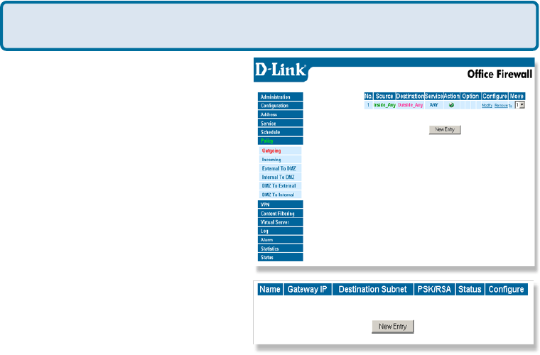
Step 4 Click on Policy and verify that
you have an Outgoing policy configured.
If not, click on New Entry, accept the
default values, and click OK.
Step 5 Click on VPN and then click
New Entry.
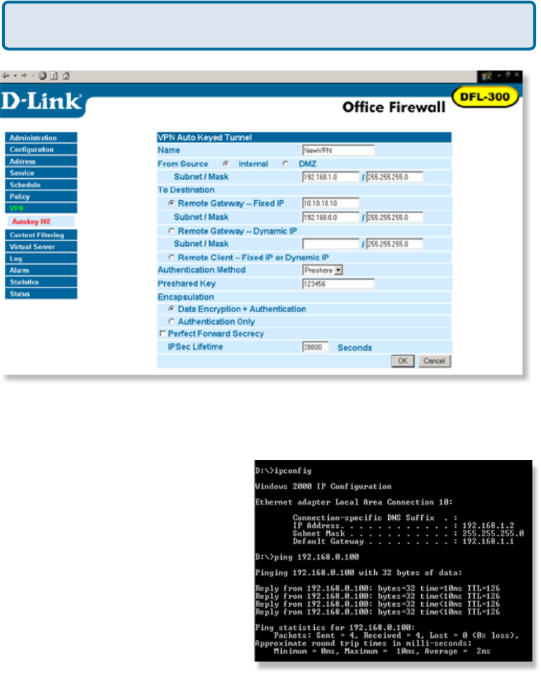
Step 6 Give the VPN connection a name with no spaces.
Step 7 Enter the network identifier and subnet mask of the Internal interface.
Step 8 In the To Destination section, select either Remote Gateway—Fixed IP or
Remote Gateway—Dynamic IP. Enter the WAN IP address of the DI-824VUP if Remote
Gateway—Fixed IP is selected.
Step 9 Enter the network identifier corresponding subnet mask of the DI-824VUP´s
LAN.
Step 10 Enter a Preshared Key. The Preshared Key needs to be identical to the one
configured on the DI-824VUP.
Step 11 Select Data Encryption and Authentication as the Encapsulation and click
OK.
How can I set up my DI-824VUP to work with a DFL-300 Firewall?
(continued)
132
After you have configured both the router and firewall, you need to establish a
connection.
Frequently Asked Questions (continued)
Step 2 Once you begin to receive replies, the VPN connection has been established.
Step 1 Open a command prompt and
from a computer connected to the Inter-
nal interface of the DFL-300 and ping the
IP address of a computer that is on the
internal LAN of the DI-824VUP, or vice
versa.
How can I set up my DI-824VUP to work with a DFL-300 Firewall?
(continued)
133
Frequently Asked Questions (continued)
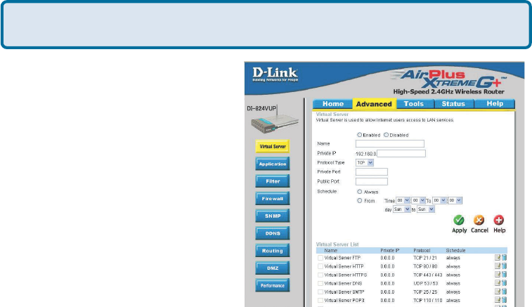
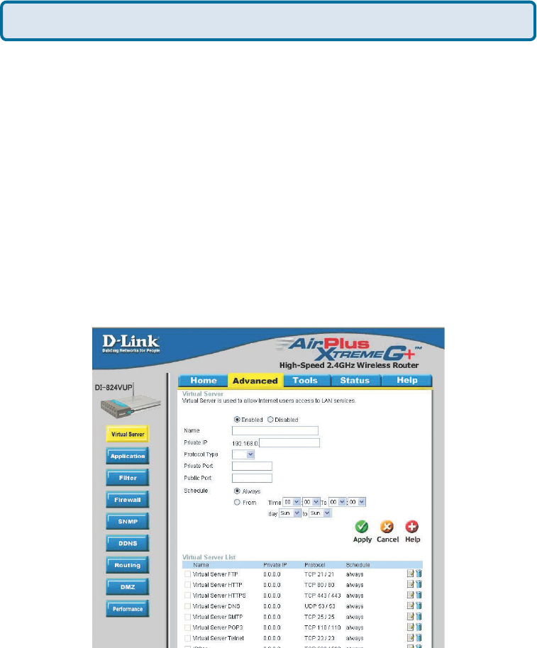
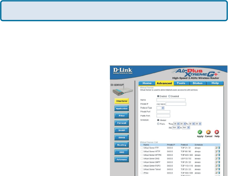
How do I open ports on my DI-824VUP?
To allow traffic from the internet to
enter your local network, you will
need to open up ports or the router
will block the request.
Step 1 Open your Web browser
and enter the IP Address of your D-
Link router (192.168.0.1). Enter
username (admin) and your
password (blank by default).
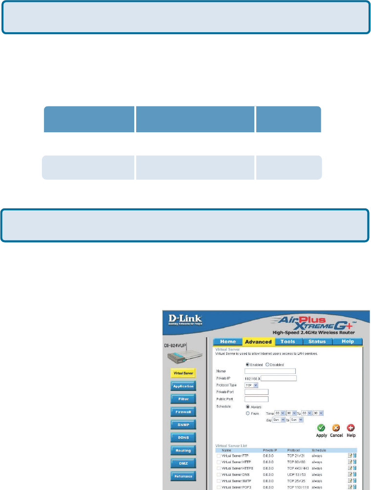
Step 2 Click on Advanced on top
and then click Virtual Server on
the left side.
Step 3 Check Enabled to activate
entry.
Step 4 Enter a name for your virtual server entry.
Step 5 Next to Private IP, enter the IP Address of the computer on your local
network that you want to allow the incoming service to.
Step 6 Choose Protocol Type - either TCP, UDP, or both. If you are not sure, select
both.
Step 7 Enter the port information next to Private Port and Public Port. The private
and public ports are usually the same. The public port is the port seen from the WAN
side, and the private port is the port being used by the application on the computer
within your local network.
Step 8 Enter the Schedule information.
Step 9 Click Apply and then click Continue.
Note: Make sure DMZ host is disabled. If DMZ is enabled, it will disable all Virtual
Server entries.
Because our routers use NAT (Network Address Translation), you can only open a
specific port to one computer at a time. For example: If you have 2 web servers on
your network, you cannot open port 80 to both computers. You will need to configure
1 of the web servers to use port 81. Now you can open port 80 to the first computer
and then open port 81 to the other computer.
134
Frequently Asked Questions (continued)
What is DMZ?
Demilitarized Zone:
In computer networks, a DMZ (demilitarized zone) is a computer host or small
network inserted as a neutral zone between a company´s private network and the
outside public network. It prevents outside users from getting direct access to a
server that has company data. (The term comes from the geographic buffer zone that
was set up between North Korea and South Korea following the UN police action in
the early 1950s.) A DMZ is an optional and more secure approach to a firewall and
effectively acts as a proxy server as well.
In a typical DMZ configuration for a small company, a separate computer (or host in
network terms) receives requests from users within the private network for access to
Web sites or other companies accessible on the public network. The DMZ host then
initiates sessions for these requests on the public network. However, the DMZ host is
not able to initiate a session back into the private network. It can only forward packets
that have already been requested.
Users of the public network outside the company can access only the DMZ host. The
DMZ may typically also have the company´s Web pages so these could be served to
the outside world. However, the DMZ provides access to no other company data. In
the event that an outside user penetrated the DMZ hosts security, the Web pages
might be corrupted but no other company information would be exposed. D-Link, a
leading maker of routers, is one company that sells products designed for setting up
a DMZ
How do I configure the DMZ Host?
The DMZ feature allows you to forward all incoming ports to one computer on the local
network. The DMZ, or Demilitarized Zone, will allow the specified computer to be
exposed to the Internet. DMZ is useful when a certain application or game does not
work through the firewall. The computer that is configured for DMZ will be completely
vulnerable on the Internet, so it is suggested that you try opening ports from the
Virtual Server or Firewall settings before using DMZ.
Step 1 Find the IP address of the computer you want to use as the DMZ host.
To find out how to locate the IP Address of the computer in Windows XP/2000/ME/9x
or Macintosh operating systems please refer to Step 4 of the first question in this
section (Frequently Asked Questions).
135
Frequently Asked Questions (continued)
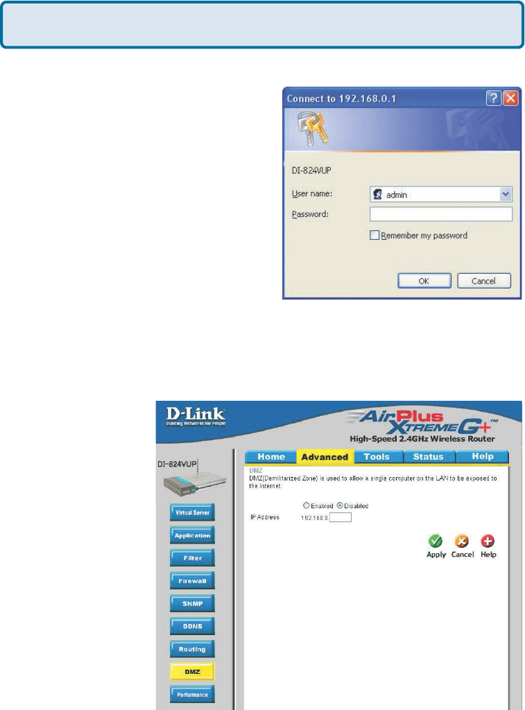
Step 2 Log into the web based configuration
of the router by typing in the IP Address of the
router (default:192.168.0.1) in your web
browser. The username is admin (all
lowercase) and the password is blank
(empty).
How do I configure the DMZ Host? (continued)
Step 3 Click the Advanced tab and then click on the DMZ button. Select Enable
and type in the IP Address from step 1.
Step 4 Click Apply
and then Continue to
save the changes.
Note: When DMZ is
enabled, Virtual Server
settings will still be
effective. Remember,
you cannot forward the
same port to multiple
IP Addresses, so the
Virtual Server settings
will take priority over
DMZ settings.
DI-624
136
Frequently Asked Questions (continued)
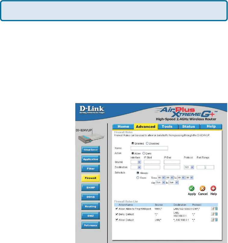
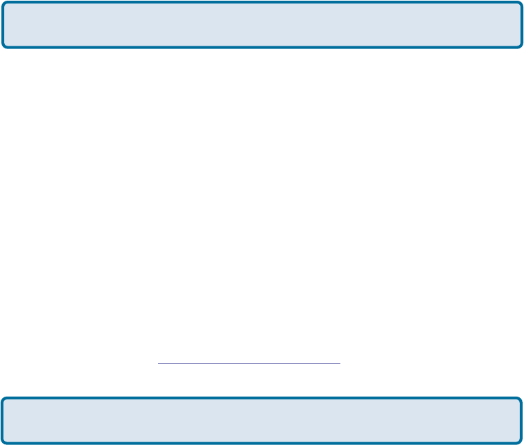
How do I open a range of ports on my DI-824VUP using Firewall rules?
Step 1 Access the router’s web configuration by entering the router’s IP Address in
your web browser. The default IP Address is 192.168.0.1. Login using your password.
The default username is “admin” and the password is blank.
If you are having difficulty accessing web management, please see the first question
in this section.
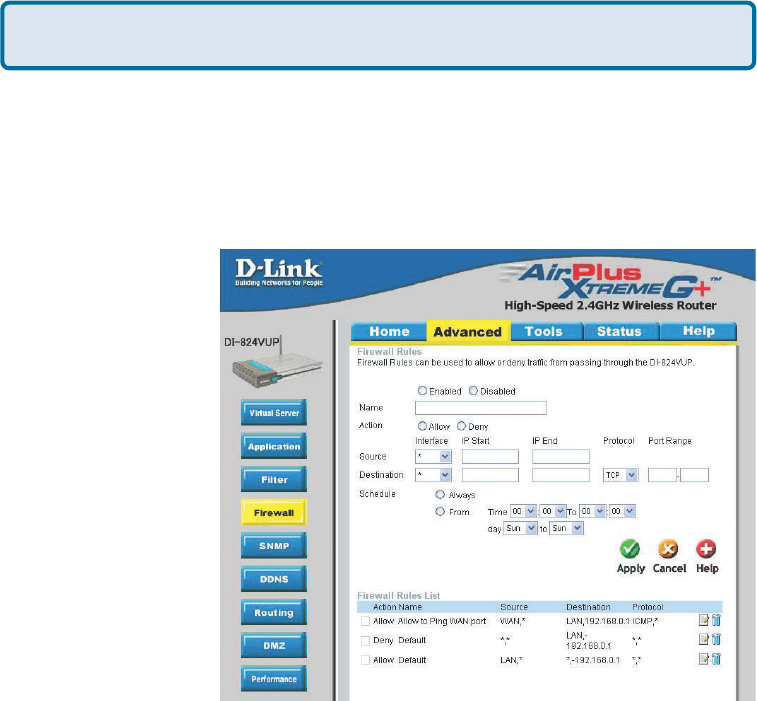
Step 2 From the web management Home page, click the Advanced tab then click
the Firewall button.
Step 3 Click on
Enabled and type in a
name for the new rule.
Step 4 Choose WAN
as the Source and
enter a range of IP
Addresses out on the
internet that you would
like this rule applied
to. If you would like
this rule to allow all
internet users to be
able to access these
ports, then put an
Asterisk in the first
box and leave the
second box empty.
Step 5 Select LAN as the Destination and enter the IP Address of the computer on
your local network that you want to allow the incoming service to. This will not work
with a range of IP Addresses.
Step 6 Enter the port or range of ports that are required to be open for the incoming
service.
Step 7 Click Apply and then click Continue.
Because our routers use NAT (Network Address Translation), you can only open a
specific port to one computer at a time. For example: If you have 2 web servers on
your network, you cannot open port 80 to both computers. You will need to configure
1 of the web servers to use port 81. Now you can open port 80 to the first computer
and then open port 81 to the other computer.
Note: Make sure DMZ host is disabled.
137
Frequently Asked Questions (continued)
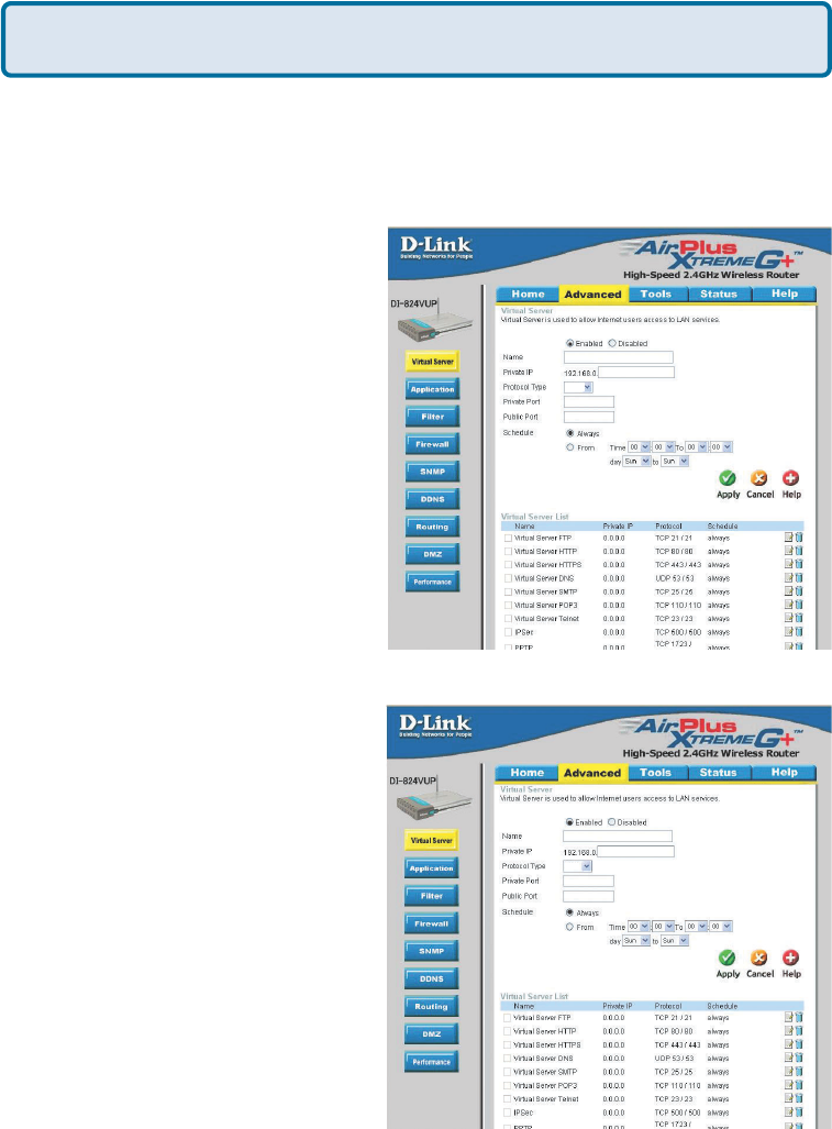
What are virtual servers?
A Virtual Server is defined as a service port, and all requests to this port will be
redirected to the computer specified by the server IP. For example, if you have an FTP
Server (port 21) at 192.168.0.5, a Web server (port 80) at 192.168.0.6, and a VPN
(port 1723) server at 192.168.0.7, then you need to specify the following virtual server
mapping table:
Server Port Server IP Enable
21 192.168.0.5 X
80 192.168.0.6 X
1723 192.168.0.7 X
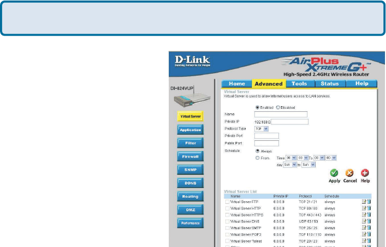
How do I use PC Anywhere with my DI-824VUP?
You will need to open 3 ports in the Virtual Server section of your D-Link router.
Step 1 Open your web browser and enter the IP Address of the router (192.168.0.1).
Step 2 Click on Advanced at the
top and then click Virtual Server
on the left side.
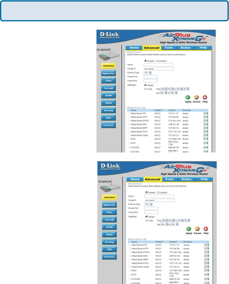
Step 3 Enter the information as
seen below. The Private IP is the
IP Address of the computer on
your local network that you want
to connect to.
Step 4 The first entry will read as
shown here:
Step 5 Click Apply and then
click Continue.
pcanywhere1
138
How do I use PC Anywhere with my DI-824VUP? (continued)
Frequently Asked Questions (continued)
Step 6 Create a second entry
as shown here:
Step 7 Click Apply and then
click Continue.
Step 8 Create a third and final
entry as shown here:
Step 9 Click Apply and then
click Continue.
Step 10 Run PCAnywhere from the remote site and use the WAN IP Address of the
router, not your computer´s IP Address.
pcanywhere2
pcanywhere3
139
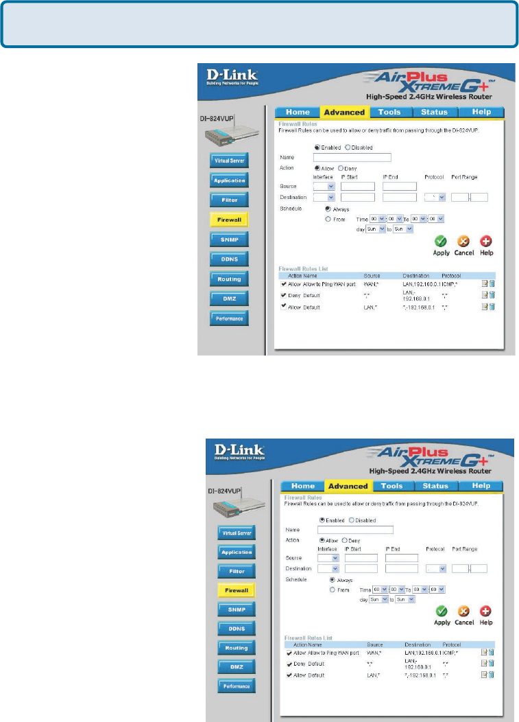
How can I use eDonkey behind my DI-824VUP?
Frequently Asked Questions (continued)
You must open ports on your router to allow incoming traffic while using eDonkey.
eDonkey uses three ports (4 if using CLI):
4661 (TCP) To connect with a server
4662 (TCP) To connect with other clients
4665 (UDP) To communicate with servers other than the one you are connected to.
4663 (TCP) *Used with the command line (CLI) client when it is configured to allow
remote connections. This is the case when using a Graphical Interface (such as the
Java Interface) with the client.
Step 1 Open your web
browser and enter the IP
Address of your router
(192.168.0.1). Enter
username (admin) and
your password (leave
blank).
Step 2 Click on
Advanced and then
click Firewall.
Step 3 Create a new
firewall rule:
Click Enabled.
Enter a name (edonkey).
Click Allow.
Next to Source, select
WAN under interface. In
the first box, enter an *.
Leave the second box
empty.
Next to Destination,
select LAN under interface. Enter the IP Address of the computer you are running
eDonkey from. Leave the second box empty. Under Protocol, select *. In the port
range boxes, enter 4661 in the first box and then 4665 in the second box. Click
Always or set a schedule.
Step 4 Click Apply and then Continue.
edonkey
WAN
LAN 192.168.0.100 4661 4665
140
Frequently Asked Questions (continued)
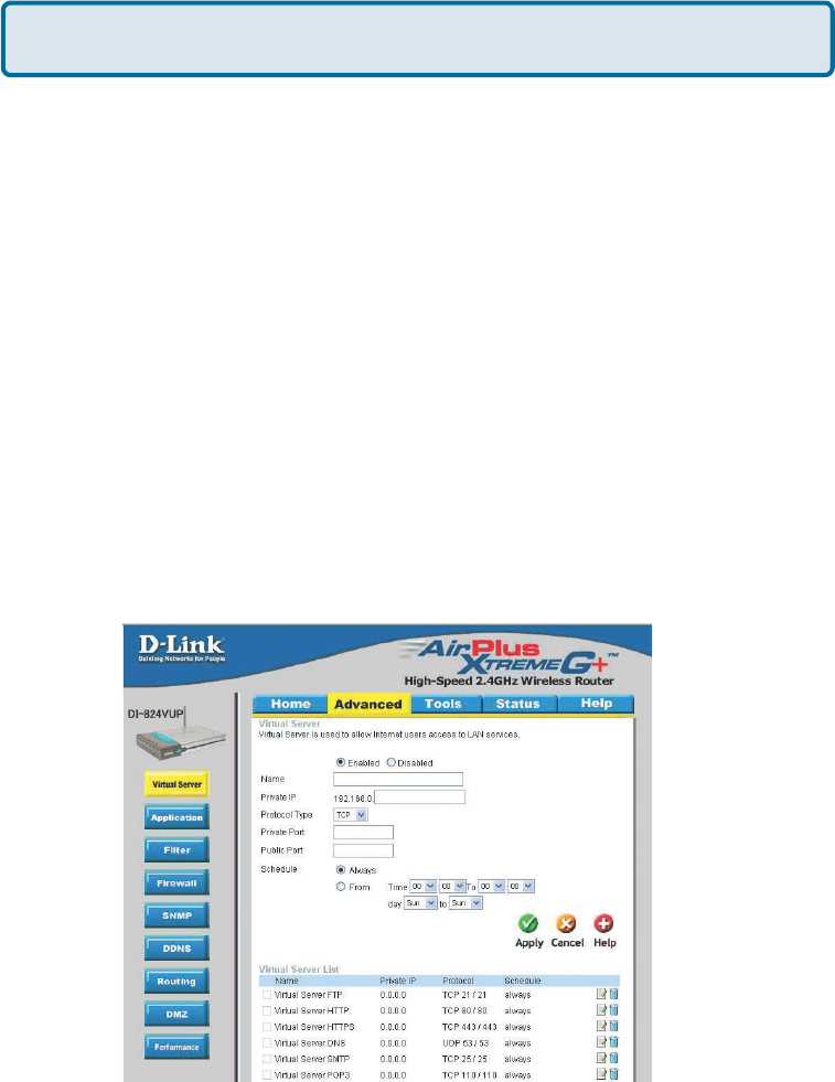
To allow you to play SOCOM and hear audio, you must download the latest firmware
for the router (if needed), enable Game Mode, and open port 6869 to the IP Address of
your Playstation.
Step 1 Upgrade firmware (follow link above).
Step 2 Open your web browser and enter the IP Address of the router (192.168.0.1).
Enter username (admin) and your password (blank by default).
Step 3 Click on the Advanced tab and then click on Virtual Server on the left side.
Step 4 You will now create a new Virtual Server entry. Click Enabled and enter a
name (socom). Enter the IP Address of your Playstation for Private IP.
Step 5 For Protocol Type select Both. Enter 6869 for both the Private Port and
Public Port. Click Always. Click Apply to save changes and then Continue
Step 6 Click on the Tools tab and then Misc on the left side.
Step 7 Make sure Gaming Mode is Enabled. If not, click Enabled. Click Apply
and then Continue.
How do I set up my DI-824VUP for SOCOM on my Playstation 2?
socom
100
6869
6869
Both
141
NAME - Gamespy1
PRIVATE IP - The IP Address of
your computer that you are
running Gamespy from.
PROTOCOL TYPE - Both
PRIVATE PORT - 3783
NAME - Gamespy2
PRIVATE IP - The IP Address of
your computer that you are
running Gamespy from.
PROTOCOL TYPE - Both
PRIVATE PORT - 6500
PUBLIC PORT - 6500
SCHEDULE - Always.
Frequently Asked Questions (continued)
Step 1 Open your web browser and enter the IP Address of the router (192.168.0.1).
Enter admin for the username and your password (blank by default).
Step 2 Click on the Advanced tab and then click Virtual Server on the left side.
Step 3 You will create 2 entries.
Step 4 Click Enabled and enter
Settings:
Click Apply and then continue
Step 5 Enter 2nd entry:
Click Enabled
Click Apply and then continue.
How can I use Gamespy behind my DI-824VUP?
Both
100
gamespy1
3783
3783
100
gamespy2
Both
6500
6500
142
Make sure that you did not enable proxy/firewall in the KaZaA software.
Frequently Asked Questions (continued)
How do I configure my DI-824VUP for KaZaA and Grokster?
The following is for KaZaA, Grokster, and others using the FastTrack P2P file sharing
system.
In most cases, you do not have to configure anything on the router or on the Kazaa
software. If you are having problems, please follow steps below:
Step 1 Enter the IP Address of your router in a web browser (192.168.0.1).
Step 2 Enter your username (admin) and your password (blank by default).
Step 3 Click on Advanced and then click Virtual Server.
Step 4 Click Enabled and then enter a Name (kazaa for example).
Step 5 Enter the IP Address of the computer you are running KaZaA from in the
Private IP box. Select TCP for the Protocol Type.
Step 6 Enter 1214 in the Private and Public Port boxes. Click Always under
schedule or set a time range. Click Apply.
kazaa
100
6500
6500
143
Frequently Asked Questions (continued)
How do I configure my DI-824VUP to play Warcraft 3?
To hose a Warcraft 3 game, you must open ports on your router to allow incoming
traffic. To play a game, you do not have to configure your router.
Warcraft 3 (Battlenet) uses port 6112.
For the DI-824VUP:
Step 1 Open your web browser and
enter the IP Address of your router
(192.168.0.1). Enter username (admin)
and your password (leave blank).
Step 2 Click on Advanced and then
click Virtual Server.
Step 3 Create a new entry: Click
Enabled. Enter a name (warcraft3).
Private IP - Enter the IP Address of the
computer you want to host the game.
Select Both for Protocol Type Enter
6112 for both Private Port and Public
Port Click Always or set a schedule.
Step 4 Click Apply and then Continue.
Note: If you want multiple computers from you LAN to play in the same game that
you are hosting, then repeat the steps above and enter the IP Addresses of the other
computers. You will need to change ports. Computer #2 can use port 6113, computer
#3 can use 6114, and so on.
You will need to change the port information within the Warcraft 3 software for
computers #2 and up.
Configure the Game Port information on each computer:
Start Warcraft 3 on each computer, click Options > Gameplay. Scroll down and you
should see Game Port. Enter the port number as you entered in the above steps.
warcraft3
100
6500
6500
Both
144
Frequently Asked Questions (continued)
How do I use NetMeeting with my DI-824VUP?
Unlike most TCP/IP applications, NetMeeting uses DYNAMIC PORTS instead of
STATIC PORTS. That means that each NetMeeting connection is somewhat different
than the last. For instance, the HTTP web site application uses port 80. NetMeeting
can use any of over 60,000 different ports.
All broadband routers using (only) standard NAT and all internet sharing programs like
Microsoft ICS that use (only) standard NAT will NOT work with NetMeeting or other
h.323 software packages.
The solution is to put the router in DMZ.
Note: A few hardware manufacturers have taken it on themselves to actually provide
H.323 compatibility. This is not an easy task since the router must search each
incoming packet for signs that it might be a netmeeting packet. This is a whole lot
more work than a router normally does and may actually be a weak point in the
firewall. D-Link is not one of the manufacturers.
To read more on this visit http://www.HomenetHelp.com
How do I set up my DI-824VUP to use iChat? -for Macintosh users-
You must open ports on your router to allow incoming traffic while using iChat.
iChat uses the following ports: 5060 (UDP), 5190 (TCP), and File Sharing 16384-
16403 (UDP) to video conference with other clients.
Step 1 Open your web browser and enter the IP Address of your router
(192.168.0.1). Enter username (admin) and your password (leave blank).
Step 2 Click on Advanced and then click Firewall.
145
Frequently Asked Questions (continued)
Step 3 Create a new firewall
rule:
Leave the second box empty. Under Protocol, select UDP. In the port range boxes,
enter 5060 in the first box and
leave the second box empty.
Click Always or set a
schedule.
Step 4 Click Apply and then
Continue.
Step 5
Repeat steps 3 and 4 enter
ichat2 and open ports 16384-
16403 (UDP).
How do I set up my DI-824VUP to use iChat? -for Macintosh users-
(continued)
Click Enabled.
Enter a name (ichat1).
Click Allow.
Next to Source, select
WAN under interface.
In the first box, enter an
*.
Leave the second box
empty.
Next to Destination,
select LAN under
interface.
Enter the IP Address of
the computer you are
running iChat from.
ichat2
WAN
LAN 192.168.0.100 UDP 1638 1640
ichat1
WAN
LAN 192.168.0.100 UDP 5060
146
Frequently Asked Questions (continued)
If using Mac OS X Firewall, you may need to temporarily turn off the firewall in
the Sharing preference pane on both computers.
To use the Mac OS X Firewall, you must open the same ports as in the router:
Step 1 Choose Apple menu > System Preferences.
Step 2 Choose View > Sharing.
Step 3 Click the Firewall tab.
Step 4 Click New.
Step 5 Choose Other from the Port Name pop-up menu.
Step 6 In the Port Number, Range or Series field, type in: 5060, 16384-16403.
Step 7 In the Description field type in: iChat AV
Step 8 Click OK.
For File Sharing:
Step 1 Click on Advanced and
then Virtual Server.
Step 2 Check Enabled to
activate entry.
Step 3 Enter a name for your
virtual server entry (ichat3).
Step 4 Next to Private IP, enter
the IP Address of the computer on
your local network that you want
to allow the incoming service to.
Step 5 Select TCP for Protocol
Type.
Step 6 Enter 5190 next to Private
Port and Public Port.
Stsp 7 Click Always or configure a schedule.
Step 8 Click Apply and then Continue.
How do I set up my DI-824VUP to use iChat? -for Macintosh users-
(continued)
ichat3
100
6500
6500

147
Frequently Asked Questions (continued)
How do I send or receive a file via iChat when the Mac OSX firewall
is active? - for Macintosh users - Mac OS X 10.2 and later
“iChat cannot send or receive a file when the Mac OS X firewall is active in its default
state. If you have opened the AIM port, you may be able to receive a file but not send
them.
In its default state, the Mac OS X firewall blocks file transfers using iChat or America
Online AIM software. If either the sender or receiver has turned on the Mac OS X firewall,
the transfer may be blocked.
The simplest workaround is to temporarily turn off the firewall in the Sharing preference
pane on both computers. This is required for the sender. However, the receiver may keep
the firewall on if the AIM port is open. To open the AIM port:
If you do not want to turn off the firewall at the sending computer, a different file sharing
service may be used instead of iChat. The types of file sharing available in Mac OS X are
outlined in technical document 106461, "Mac OS X: File Sharing" in the AppleCare Knowl-
edge base online.
Note: If you use a file sharing service when the firewall is turned on, be sure to click the
Firewall tab and select the service you have chosen in the "Allow" list. If you do not do
this, the firewall will also block the file sharing service. “
The following information is from the online Macintosh AppleCare knowledge base:
Step 1 Choose Apple menu > System Preferences.
Step 2 Choose View > Sharing.
Step 3 Click the Firewall tab.
Step 4 Click New.
Step 5 Choose AOL IM from the Port Name pop-up menu. The number 5190
should already be filled in for you.
Step 6 Click OK.
148
What is NAT?
NAT stands for Network Address Translator. It is proposed and described in RFC-
1631 and is used for solving the IP Address depletion problem. Each NAT box has a
table consisting of pairs of local IP Addresses and globally unique addresses, by
which the box can “translate” the local IP Addresses to global address and vice versa.
Simply put, it is a method of connecting multiple computers to the Internet (or any
other IP network) using one IP Address.
D-Link´s broadband routers (ie: DI-824VUP) support NAT. With proper configuration,
multiple users can access the Internet using a single account via the NAT device.
For more information on RFC-1631: The IP Network Address Translator (NAT), visit
http://www.faqs.org/rfcs/rfc1631.html
Frequently Asked Questions (continued)
149
You can find the most recent software and user documentation on the D-Link website.
D-Link provides free technical support for customers within the United States for the
duration of the warranty period on this product.
U.S. customers can contact D-Link technical support through our web site,
or by phone.
D-Link Technical Support over the Telephone:
(877) 453-5465
24 hours a day, seven days a week.
D-Link Technical Support over the Internet:
http://support.dlink.com
When contacting technical support, you will need the information below. (Please look
on the back side of the unit.)
Contacting Technical Support
Serial number of the unit
Model number or product name
Software type and version number
150
Subject to the terms and conditions set forth herein, D-Link Systems, Inc. (“D-Link”) provides this Limited
warranty for its product only to the person or entity that originally purchased the product from:
D-Link or its authorized reseller or distributor and
Products purchased and delivered within the fifty states of the United States, the District of
Columbia, U.S. Possessions or Protectorates, U.S. Military Installations, addresses with an
APO or FPO.
Limited Warranty: D-Link warrants that the hardware portion of the D-Link products described
below will be free from material defects in workmanship and materials from the date of original retail
purchase of the product, for the period set forth below applicable to the product type (“Warranty
Period”), except as otherwise stated herein.
3-Year Limited Warranty for the Product(s) is defined as follows:
Hardware (excluding power supplies and fans) Three (3) Years
Power Supplies and Fans One (1) Year
Spare parts and spare kits Ninety (90) days
D-Link’s sole obligation shall be to repair or replace the defective Hardware during the Warranty Period
at no charge to the original owner or to refund at D-Link’s sole discretion. Such repair or replacement will
be rendered by D-Link at an Authorized D-Link Service Office. The replacement Hardware need not be
new or have an identical make, model or part. D-Link may in its sole discretion replace the defective
Hardware (or any part thereof) with any reconditioned product that D-Link reasonably determines is
substantially equivalent (or superior) in all material respects to the defective Hardware. Repaired or
replacement Hardware will be warranted for the remainder of the original Warranty Period from the date
of original retail purchase. If a material defect is incapable of correction, or if D-Link determines in its sole
discretion that it is not practical to repair or replace the defective Hardware, the price paid by the original
purchaser for the defective Hardware will be refunded by D-Link upon return to D-Link of the defective
Hardware. All Hardware (or part thereof) that is replaced by D-Link, or for which the purchase price is
refunded, shall become the property of D-Link upon replacement or refund.
Limited Software Warranty: D-Link warrants that the software portion of the product (“Software”)
will substantially conform to D-Link’s then current functional specifications for the Software, as set forth
in the applicable documentation, from the date of original retail purchase of the Software for a period of
ninety (90) days (“Warranty Period”), provided that the Software is properly installed on approved
hardware and operated as contemplated in its documentation. D-Link further warrants that, during the
Warranty Period, the magnetic media on which D-Link delivers the Software will be free of physical
defects. D-Link’s sole obligation shall be to replace the non-conforming Software (or defective media)
with software that substantially conforms to D-Link’s functional specifications for the Software or to
refund at D-Link’s sole discretion. Except as otherwise agreed by D-Link in writing, the replacement
Software is provided only to the original licensee, and is subject to the terms and conditions of the
license granted by D-Link for the Software. Software will be warranted for the remainder of the original
Warranty Period from the date or original retail purchase. If a material non-conformance is incapable of
correction, or if D-Link determines in its sole discretion that it is not practical to replace the non-
conforming Software, the price paid by the original licensee for the non-conforming Software will be
refunded by D-Link; provided that the non-conforming Software (and all copies thereof) is first returned
to D-Link. The license granted respecting any Software for which a refund is given automatically
terminates.
Non-Applicability of Warranty: The Limited Warranty provided hereunder for hardware and software
of D-Link’s products will not be applied to and does not cover any refurbished product and any product
purchased through the inventory clearance or liquidation sale or other sales in which D-Link, the sellers,
or the liquidators expressly disclaim their warranty obligation pertaining to the product and in that case,
the product is being sold “As-Is” without any warranty whatsoever including, without limitation, the
Limited Warranty as described herein, notwithstanding anything stated herein to the contrary.
Submitting A Claim: The customer shall return the product to the original purchase point based on its
return policy. In case the return policy period has expired and the product is within warranty, the
customer shall submit a claim to D-Link as outlined below:
The customer must submit with the product as part of the claim a written description of the
Hardware defect or Software nonconformance in sufficient detail to allow D-Link to confirm
the same.
Warranty and Registration
151
The original product owner must obtain a Return Material Authorization (“RMA”) number from
the Authorized D-Link Service Office and, if requested, provide written proof of purchase of
the product (such as a copy of the dated purchase invoice for the product) before the
warranty service is provided.
After an RMA number is issued, the defective product must be packaged securely in the
original or other suitable shipping package to ensure that it will not be damaged in transit, and
the RMA number must be prominently marked on the outside of the package. Do not include any
manuals or accessories in the shipping package. D-Link will only replace the defective portion
of the Product and will not ship back any accessories.
The customer is responsible for all in-bound shipping charges to D-Link. No Cash on Delivery
(“COD”) is allowed. Products sent COD will either be rejected by D-Link or become the
property of D-Link. Products shall be fully insured by the customer and shipped to D-Link
Systems, Inc., 17595 Mt. Herrmann, Fountain Valley, CA 92708. D-Link will not be held
responsible for any packages that are lost in transit to D-Link. The repaired or replaced
packages will be shipped to the customer via UPS Ground or any common carrier selected by
D-Link, with shipping charges prepaid. Expedited shipping is available if shipping charges are
prepaid by the customer and upon request.
D-Link may reject or return any product that is not packaged and shipped in strict compliance with the
foregoing requirements, or for which an RMA number is not visible from the outside of the package. The
product owner agrees to pay D-Link’s reasonable handling and return shipping charges for any product
that is not packaged and shipped in accordance with the foregoing requirements, or that is determined
by D-Link not to be defective or non-conforming.
What Is Not Covered: This limited warranty provided by D-Link does not cover: Products, if in D-Link’s
judgment, have been subjected to abuse, accident, alteration, modification, tampering, negligence, misuse,
faulty installation, lack of reasonable care, repair or service in any way that is not contemplated in the
documentation for the product, or if the model or serial number has been altered, tampered with, defaced
or removed; Initial installation, installation and removal of the product for repair, and shipping costs;
Operational adjustments covered in the operating manual for the product, and normal maintenance;
Damage that occurs in shipment, due to act of God, failures due to power surge, and cosmetic damage;
Any hardware, software, firmware or other products or services provided by anyone other than D-
Link; Products that have been purchased from inventory clearance or liquidation sales or other sales in
which D-Link, the sellers, or the liquidators expressly disclaim their warranty obligation pertaining to the
product. Repair by anyone other than D-Link or an Authorized D-Link Service Office will void this
Warranty.
Disclaimer of Other Warranties: EXCEPT FOR THE LIMITED WARRANTY SPECIFIED HEREIN, THE
PRODUCT IS PROVIDED “AS-IS” WITHOUT ANY WARRANTY OF ANY KIND WHATSOEVER INCLUDING,
WITHOUT LIMITATION, ANY WARRANTY OF MERCHANTABILITY, FITNESS FOR A PARTICULAR PURPOSE
AND NON-INFRINGEMENT. IF ANY IMPLIED WARRANTY CANNOT BE DISCLAIMED IN ANY TERRITORY
WHERE A PRODUCT IS SOLD, THE DURATION OF SUCH IMPLIED WARRANTY SHALL BE LIMITED TO
NINETY (90) DAYS. EXCEPT AS EXPRESSLY COVERED UNDER THE LIMITED WARRANTY PROVIDED
HEREIN, THE ENTIRE RISK AS TO THE QUALITY, SELECTION AND PERFORMANCE OF THE PRODUCT IS
WITH THE PURCHASER OF THE PRODUCT.
Limitation of Liability: TO THE MAXIMUM EXTENT PERMITTED BY LAW, D-LINK IS NOT LIABLE
UNDER ANY CONTRACT, NEGLIGENCE, STRICT LIABILITY OR OTHER LEGAL OR EQUITABLE THEORY
FOR ANY LOSS OF USE OF THE PRODUCT, INCONVENIENCE OR DAMAGES OF ANY CHARACTER,
WHETHER DIRECT, SPECIAL, INCIDENTAL OR CONSEQUENTIAL (INCLUDING, BUT NOT LIMITED TO,
DAMAGES FOR LOSS OF GOODWILL, LOSS OF REVENUE OR PROFIT, WORK STOPPAGE, COMPUTER
FAILURE OR MALFUNCTION, FAILURE OF OTHER EQUIPMENT OR COMPUTER PROGRAMS TO WHICH D-
LINK’S PRODUCT IS CONNECTED WITH, LOSS OF INFORMATION OR DATA CONTAINED IN, STORED ON,
OR INTEGRATED WITH ANY PRODUCT RETURNED TO D-LINK FOR WARRANTY SERVICE) RESULTING
FROM THE USE OF THE PRODUCT, RELATING TO WARRANTY SERVICE, OR ARISING OUT OF ANY
BREACH OF THIS LIMITED WARRANTY, EVEN IF D-LINK HAS BEEN ADVISED OF THE POSSIBILITY OF
SUCH DAMAGES. THE SOLE REMEDY FOR A BREACH OF THE FOREGOING LIMITED WARRANTY IS
REPAIR, REPLACEMENT OR REFUND OF THE DEFECTIVE OR NON-CONFORMING PRODUCT. THE MAXIMUM
LIABILITY OF D-LINK UNDER THIS WARRANTY IS LIMITED TO THE PURCHASE PRICE OF THE PRODUCT
COVERED BY THE WARRANTY. THE FOREGOING EXPRESS WRITTEN WARRANTIES AND REMEDIES
ARE EXCLUSIVE AND ARE IN LIEU OF ANY OTHER WARRANTIES OR REMEDIES, EXPRESS, IMPLIED OR
STATUTORY

152
Governing Law: This Limited Warranty shall be governed by the laws of the State of California. Some
states do not allow exclusion or limitation of incidental or consequential damages, or limitations on how
long an implied warranty lasts, so the foregoing limitations and exclusions may not apply. This limited
warranty provides specific legal rights and the product owner may also have other rights which vary
from state to state.
Trademarks: D-Link is a registered trademark of D-Link Systems, Inc. Other trademarks or registered
trademarks are the property of their respective manufacturers or owners.
Copyright Statement: No part of this publication or documentation accompanying this Product may
be reproduced in any form or by any means or used to make any derivative such as translation,
transformation, or adaptation without permission from D-Link Corporation/D-Link Systems, Inc., as
stipulated by the United States Copyright Act of 1976. Contents are subject to change without prior
notice. Copyright© 2002 by D-Link Corporation/D-Link Systems, Inc. All rights reserved.
CE Mark Warning: This is a Class B product. In a domestic environment, this product may cause radio
interference, in which case the user may be required to take adequate measures.
FCC Statement: This equipment has been tested and found to comply with the limits for a Class B
digital device, pursuant to part 15 of the FCC Rules. These limits are designed to provide reasonable
protection against harmful interference in a residential installation. This equipment generates, uses, and
can radiate radio frequency energy and, if not installed and used in accordance with the instructions,
may cause harmful interference to radio communication. However, there is no guarantee that interference
will not occur in a particular installation. If this equipment does cause harmful interference to radio or
television reception, which can be determined by turning the equipment off and on, the user is encouraged
to try to correct the interference by one or more of the following measures:
Reorient or relocate the receiving antenna.
Increase the separation between the equipment and receiver.
Connect the equipment into an outlet on a circuit different from that to which the receiver is
connected.
Consult the dealer or an experienced radio/TV technician for help.
Register online your D-Link product at http://support.dlink.com/register/
FCC Caution: Any changes or modifications not expressly approved by the party responsible for
compliance could void the user’s authority to operate this equipment.
This device complies with Part 15 of the FCC Rules. Operation is subject to the following two
conditions: (1) This device may not cause harmful interference, and (2) this device must accept
any interference received, including interference that may cause undesired operation.
IMPORTANT NOTE:
FCC Radiation Exposure Statement:
This equipment complies with FCC radiation exposure limits set forth for an uncontrolled
environment. The antenna(s) used for this equipment must be installed to provide a separation
distance of at least eight inches (20 cm) from all persons.
This transmitter must not be operated in conjunction with any other antenna.
02/10/03
The Manufacturer is not responsible for any radio or TV interference caused by unauthorized
modifications to this equipment; such modifications could void the user’s authority to operate the
equipment.