D Link WL3600APA1 802.11n single band Unified Access Point User Manual UserMan KA2WL3600APA1 rev 1
D Link Corporation 802.11n single band Unified Access Point UserMan KA2WL3600APA1 rev 1
D Link >
UserMan_KA2WL3600APA1_rev. 1

©Copyright 2011. All rights reserved.
Unified Access Point
Administrator's Guide
Product Model: DWL-3600AP
DWL-6600AP
DWL-8600AP
Unified Wired & Wireless Access System
Release 2.0
November 2011

D-Link UnifiedAccessPointAdministrator’sGuide
November2011 Page2
UnifiedAccessPointAdministrator’sGuide

D-Link UnifiedAccessPointAdministrator’sGuide
November2011 Page3
UnifiedAccessPointAdministrator’sGuide
TableofContents
Section1:AboutThisDocument ..................................................................................... 12
DocumentOrganization ............................................................................................................................... 12
AdditionalDocumentation...........................................................................................................................12
DocumentConventions................................................................................................................................13
OnlineHelp,SupportedBrowsers,andLimitations ....................................................................................14
Section2:GettingStarted ............................................................................................... 15
Administrator’sComputerRequirements ...................................................................................................16
WirelessClientRequirements......................................................................................................................17
DynamicandStaticIPAddressingontheAP...............................................................................................17
RecoveringanIPAddress.......................................................................................................................18
DiscoveringaDynamicallyAssignedIPAddress ....................................................................................18
InstallingtheUAP.........................................................................................................................................19
BasicSettings................................................................................................................................................22
ConnectingtotheAPWebInterfacebyUsingtheIPv6Address...........................................................24
UsingtheCLItoViewtheIPAddress...........................................................................................................24
ConfiguringtheEthernetSettings................................................................................................................25
UsingtheCLItoConfigureEthernetSettings.........................................................................................26
ConfiguringIEEE802.1XAuthentication......................................................................................................27
UsingtheCLItoConfigure802.1XAuthenticationInformation ............................................................27
VerifyingtheInstallation..............................................................................................................................28
ConfiguringSecurityontheWirelessAccessPoint .....................................................................................29
Section3:ViewingAccessPointStatus ............................................................................ 30
ViewingInterfaceStatus ..............................................................................................................................31
WiredSettings(InternalInterface) ........................................................................................................31
WirelessSettings....................................................................................................................................31
ViewingEvents .............................................................................................................................................32
ConfiguringPersistentLoggingOptions.................................................................................................32
ConfiguringtheLogRelayHostforKernelMessages ............................................................................34
EnablingorDisablingtheLogRelayHostontheEventsPage ...............................................................34
ViewingTransmitandReceiveStatistics .....................................................................................................36
ViewingAssociatedWirelessClientInformation ........................................................................................38
ViewingTSPECClientAssociations ..............................................................................................................39
LinkIntegrityMonitoring .......................................................................................................................41
ViewingRogueAPDetection .......................................................................................................................41

D-Link UnifiedAccessPointAdministrator’sGuide
November2011 Page4
UnifiedAccessPointAdministrator’sGuide
SavingandImportingtheKnownAPList ...............................................................................................44
ViewingManagedAPDHCPInformation.....................................................................................................45
ViewingTSPECStatusandStatisticsInformation........................................................................................45
ViewingTSPECAPStatisticsInformation.....................................................................................................47
ViewingRadioStatisticsInformation ..........................................................................................................48
ViewingEmailAlertOperationalStatus ......................................................................................................50
Section4:ManagingtheAccessPoint.............................................................................. 51
EthernetSettings ..........................................................................................................................................51
WirelessSettings ..........................................................................................................................................54
Usingthe802.11hWirelessMode.........................................................................................................57
EnablingAeroScout™EngineSupport ...................................................................................................57
ModifyingRadioSettings .............................................................................................................................58
ConfiguringRadioandVAPScheduler .........................................................................................................65
SchedulerAssociationSettings ....................................................................................................................68
VirtualAccessPointSettings........................................................................................................................70
None(Plain‐text)....................................................................................................................................74
StaticWEP..............................................................................................................................................74
StaticWEPRules .............................................................................................................................76
IEEE802.1X ............................................................................................................................................76
WPAPersonal ........................................................................................................................................78
WPAEnterprise......................................................................................................................................79
ConfiguringtheWirelessDistributionSystem(WDS) .................................................................................81
WEPonWDSLinks .................................................................................................................................84
WPA/PSKonWDSLinks .........................................................................................................................84
ControllingAccessbyMACAuthentication .................................................................................................85
ConfiguringaMACFilterandStationListontheAP..............................................................................85
ConfiguringMACAuthenticationontheRADIUSServer .......................................................................87
ConfiguringLoadBalancing..........................................................................................................................88
ManagedAccessPointOverview.................................................................................................................89
TransitioningBetweenModes...............................................................................................................89
ConfiguringManagedAccessPointSettings..........................................................................................90
Configuring802.1XAuthentication..............................................................................................................92
CreatingaManagementAccessControlList ...............................................................................................94
Section5:ConfiguringAccessPointServices.................................................................... 95
ConfiguringSNMPontheAccessPoint .......................................................................................................95
WebServerSettings .....................................................................................................................................99

D‐Link UnifiedAccessPointAdministrator’sGuide
November2011 Page5
UnifiedAccessPointAdministrator’sGuide
SettingtheSSHStatus ................................................................................................................................101
SettingtheTelnetStatus ............................................................................................................................101
ConfiguringQualityofService....................................................................................................................102
ConfiguringEmailAlert ..............................................................................................................................106
EnablingtheTimeSettings(NTP)...............................................................................................................109
Section6:ConfiguringSNMPv3 ..................................................................................... 111
ConfiguringSNMPv3Views........................................................................................................................111
ConfiguringSNMPv3Groups......................................................................................................................113
ConfiguringSNMPv3Users ........................................................................................................................115
ConfiguringSNMPv3Targets .....................................................................................................................116
Section7:MaintainingtheAccessPoint ........................................................................ 117
SavingtheCurrentConfigurationtoaBackupFile....................................................................................117
RestoringtheConfigurationfromaPreviouslySavedFile........................................................................118
PerformingAPMaintenance......................................................................................................................120
ResettingtheFactoryDefaultConfiguration .......................................................................................120
RebootingtheAccessPoint .................................................................................................................120
UpgradingtheFirmware ............................................................................................................................120
PacketCaptureConfigurationandSettings...............................................................................................122
PacketCaptureStatus..........................................................................................................................124
PacketCaptureParameterConfiguration............................................................................................124
PacketFileCapture ..............................................................................................................................125
RemotePacketCapture .......................................................................................................................125
PacketCaptureFileDownload.............................................................................................................127
Section8:ConfiguringClientQualityofService ............................................................. 128
ConfiguringVAPQoSParameters ..............................................................................................................128
ManagingClientQoSACLs .........................................................................................................................131
IPv4andIPv6ACLs ...............................................................................................................................131
MACACLs.............................................................................................................................................131
ACLConfigurationProcess ...................................................................................................................131
CreatingaDiffServClassMap ....................................................................................................................138
DefiningDiffServ ..................................................................................................................................138
CreatingaDiffServPolicyMap...................................................................................................................144
ClientQoSStatus ........................................................................................................................................146
ConfiguringRADIUS‐AssignedClientQoSParameters..............................................................................147
Section9:ClusteringMultipleAPs ................................................................................. 149
ManagingAccessPointsintheCluster ......................................................................................................149

D-Link UnifiedAccessPointAdministrator’sGuide
November2011 Page6
UnifiedAccessPointAdministrator’sGuide
ClusteringSingleandDualRadioAPs ..................................................................................................149
ViewingandConfiguringClusterMembers .........................................................................................149
RemovinganAccessPointfromtheCluster ........................................................................................151
AddinganAccessPointtoaCluster.....................................................................................................152
NavigatingtoConfigurationInformationforaSpecificAP..................................................................152
NavigatingtoanAPbyUsingitsIPAddressinaURL...........................................................................152
ManagingClusterSessions.........................................................................................................................153
SortingSessionInformation.................................................................................................................154
ConfiguringandViewingChannelManagementSettings.........................................................................154
Stopping/StartingAutomaticChannelAssignment .............................................................................155
ViewingCurrentChannelAssignmentsandSettingLocks ...................................................................156
ViewingtheLastProposedSetofChanges..........................................................................................156
ConfiguringAdvancedSettings ............................................................................................................157
ViewingWirelessNeighborhoodInformation...........................................................................................158
ViewingDetailsforaClusterMember .................................................................................................160
AppendixA:DefaultAPSettings.................................................................................... 161
AppendixB:ConfigurationExamples............................................................................. 164
ConfiguringaVAP.......................................................................................................................................164
VAPConfigurationfromtheWebInterface.........................................................................................164
VAPConfigurationfromtheCLI...........................................................................................................165
VAPConfigurationUsingSNMP ...........................................................................................................166
ConfiguringRadioSettings .........................................................................................................................166
RadioConfigurationfromtheWebInterface ......................................................................................166
RadioConfigurationfromtheCLI ........................................................................................................168
RadioConfigurationUsingSNMP ........................................................................................................168
ConfiguringtheWirelessDistributionSystem...........................................................................................169
WDSConfigurationfromtheWebInterface .......................................................................................169
WDSConfigurationfromtheCLI..........................................................................................................170
WDSConfigurationUsingSNMP..........................................................................................................171
ClusteringAccessPoints.............................................................................................................................172
ClusteringAPsbyUsingtheWebInterface .........................................................................................172
ClusteringAPsbyUsingtheCLI............................................................................................................173
ClusteringAPsbyUsingSNMP.............................................................................................................174
ConfiguringClientQoS ............................................................................................................................... 174
ConfiguringQoSbyUsingtheWebInterface ......................................................................................174
ACLConfiguration.........................................................................................................................174

D-Link UnifiedAccessPointAdministrator’sGuide
November2011 Page7
UnifiedAccessPointAdministrator’sGuide
DiffServConfiguration .................................................................................................................. 176
ConfiguringQoSbyUsingtheCLI ........................................................................................................179
ACLConfiguration.........................................................................................................................179
DiffServConfiguration .................................................................................................................. 179
ACLConfiguration.........................................................................................................................180
DiffServConfiguration .................................................................................................................. 182

D-Link UnifiedAccessPointAdministrator’sGuide
November2011 Page8
UnifiedAccessPointAdministrator’sGuide
ListofFigures
Figure1:AdministratorUIOnlineHelp ............................................................................................................14
Figure2:ViewingInterfaceStatus....................................................................................................................31
Figure3:ViewingEvents ..................................................................................................................................32
Figure4:PersistentLoggingOptions................................................................................................................33
Figure5:LogRelayHost ...................................................................................................................................34
Figure6:ViewingTrafficStatistics....................................................................................................................36
Figure7:ViewingClientAssociationInformation ............................................................................................38
Figure8:ViewingTSPECClientAssociations ....................................................................................................39
Figure9:ViewingRogueandKnownAccessPoints .........................................................................................41
Figure10:ViewingTSPECStatusandStatistics ................................................................................................45
Figure11:RadioStatistics ................................................................................................................................48
Figure12:EmailAlertOperationalStatus ........................................................................................................50
Figure13:EthernetSettings.............................................................................................................................52
Figure14:WirelessInterfaceConfiguration.....................................................................................................54
Figure15:ConfiguringRadioSettings ..............................................................................................................58
Figure16:ConfiguringRadioSettings(Continued) ..........................................................................................59
Figure17:SchedulerConfiguration.................................................................................................................. 65
Figure18:ModifyRuleConfiguration ..............................................................................................................67
Figure19:SchedulerAssociation .....................................................................................................................68
Figure20:SettingUpVirtualAccessPoints......................................................................................................71
Figure21:ConfiguringWDSSettings................................................................................................................82
Figure22:ConfiguringMACAuthentication ....................................................................................................86
Figure23:ConfiguringLoadBalancing .............................................................................................................88
Figure24:ConfiguringManagedAccessPointSettings ...................................................................................90
Figure25:IEEE802.1XAuthentication.............................................................................................................92
Figure26:ManagementACL ............................................................................................................................ 94
Figure27:ModifyingSNMPSettings................................................................................................................96
Figure28:ConfiguringWebServerSettings.....................................................................................................99
Figure29:SSHStatus......................................................................................................................................101
Figure30:TelnetStatus..................................................................................................................................101
Figure31:ConfiguringQoSSettings...............................................................................................................103
Figure32:ConfiguringEmailAlert..................................................................................................................106
Figure33:SettingtheSystemTime................................................................................................................109
Figure34:SNMPv3Views...............................................................................................................................111
Figure35:SNMPv3Groups ............................................................................................................................113

D-Link UnifiedAccessPointAdministrator’sGuide
November2011 Page9
UnifiedAccessPointAdministrator’sGuide
Figure36:SNMPv3Users ...............................................................................................................................115
Figure37:SNMPv3Target..............................................................................................................................116
Figure38:Maintenance .................................................................................................................................120
Figure39:PacketCaptureConfiguration .......................................................................................................123
Figure40:VAPQoSParameters ..................................................................................................................... 129
Figure41:ClientQoSACL...............................................................................................................................132
Figure42:ClientQoSDiffServClassMap .......................................................................................................139
Figure43:ClientQoSDiffServPolicyMap......................................................................................................144
Figure44:ClientQoSStatus ...........................................................................................................................146
Figure45:ClusterInformationandMemberConfiguration ..........................................................................150
Figure46:ClusterInformationandMemberConfiguration ..........................................................................150
Figure47:SessionManagement ....................................................................................................................153
Figure48:ChannelManagement ...................................................................................................................155
Figure49:WirelessNeighborhood.................................................................................................................158
Figure50:DetailsforaClusterMemberAP...................................................................................................160

D-Link UnifiedAccessPointAdministrator’sGuide
November2011 Page10
UnifiedAccessPointAdministrator’sGuide
ListofTables
Table1:TypographicalConventions ................................................................................................................13
Table2:RequirementsfortheAdministrator’sComputer ..............................................................................16
Table3:RequirementsforWirelessClients .....................................................................................................17
Table4:BasicSettingsPage .............................................................................................................................22
Table5:CLICommandsforEthernetSetting ...................................................................................................26
Table6:CLICommandsforthe802.1XSupplicant ..........................................................................................27
Table7:LoggingOptions ..................................................................................................................................33
Table8:LogRelayHost ....................................................................................................................................34
Table9:Transmit/Receive................................................................................................................................37
Table10:AssociatedClients.............................................................................................................................38
Table11:TSPECClientAssociations .................................................................................................................39
Table12:RogueAPDetection..........................................................................................................................42
Table13:TSPECStatusandStatistics ...............................................................................................................46
Table14:TSPECAPStatistics............................................................................................................................47
Table15:RadioStatisticsInformation .............................................................................................................48
Table16:EmailAlertStatus .............................................................................................................................50
Table17:EthernetSettingsPage .....................................................................................................................52
Table18:WirelessSettings ..............................................................................................................................55
Table19:RadioSettings ...................................................................................................................................60
Table20:SchedulerConfiguration ...................................................................................................................66
Table21:SchedulerAssociationSettings.........................................................................................................69
Table22:VirtualAccessPointSettings ............................................................................................................71
Table23:StaticWEP.........................................................................................................................................74
Table24:IEEE802.1X .......................................................................................................................................76
Table25:WPAPersonal ...................................................................................................................................78
Table26:WPAEnterprise.................................................................................................................................79
Table27:WDSSettings ....................................................................................................................................83
Table28:WEPonWDSLinks............................................................................................................................84
Table29:WPA/PSKonWDSLinks ....................................................................................................................84
Table30:MACAuthentication .........................................................................................................................86
Table31:RADIUSServerAttributesforMACAuthentication ..........................................................................87
Table32:LoadBalancing..................................................................................................................................88
Table33:ManagedAccessPoint......................................................................................................................90
Table34:IEEE802.1XSupplicantAuthentication ............................................................................................92
Table35:ManagementACL .............................................................................................................................94

D-Link UnifiedAccessPointAdministrator’sGuide
November2011 Page11
UnifiedAccessPointAdministrator’sGuide
Table36:SNMPSettings ..................................................................................................................................96
Table37:WebServerSettings .........................................................................................................................99
Table38:SSHSettings ....................................................................................................................................101
Table39:TelnetSettings ................................................................................................................................101
Table40:QoSSettings....................................................................................................................................103
Table41:EmailAlertConfiguration ...............................................................................................................106
Table42:NTPSettings....................................................................................................................................110
Table43:SNMPv3Views ................................................................................................................................112
Table44:SNMPv3Groups..............................................................................................................................114
Table45:SNMPv3Users................................................................................................................................115
Table46:SNMPv3Targets .............................................................................................................................116
Table47:PacketCaptureStatus.....................................................................................................................124
Table48:PacketCaptureConfiguration ........................................................................................................124
Table49:PacketFileCapture .........................................................................................................................125
Table50:RemotePacketCapture..................................................................................................................127
Table51:PacketCaptureFileDownload........................................................................................................127
Table52:VAPQoSParameters ......................................................................................................................129
Table53:ACLConfiguration ...........................................................................................................................132
Table54:DiffServClassMap ..........................................................................................................................139
Table55:DiffServPolicyMap.........................................................................................................................145
Table56:ClientQoSStatus ............................................................................................................................146
Table57:ClientQoSRADIUSAttributes.........................................................................................................147
Table58:AccessPointsintheCluster............................................................................................................151
Table59:ClusteringOptions ..........................................................................................................................151
Table60:SessionManagement ..................................................................................................................... 153
Table61:ChannelAssignments......................................................................................................................156
Table62:LastProposedChanges...................................................................................................................156
Table63:AdvancedChannelManagementSettings......................................................................................157
Table64:WirelessNeighborhoodInformation..............................................................................................159
Table65:ClusterMemberDetails..................................................................................................................160
Table66:UAPDefaultSettings....................................................................................................................... 161

AboutThisDocument
D-Link UnifiedAccessPointAdministrator’sGuide
November2011 Page12
UnifiedAccessPointAdministrator’sGuide
Section1:AboutThisDocument
Thisguidedescribessetup,configuration,administrationandmaintenancefortheD‐LinkDWL‐x600APUnified
AccessPoint(UAP)onawirelessnetwork.ThethreeUAPmodelsintheDWL‐x600APfamilyincludethe
DWL‐3600AP,DWL‐6600AP,andDWL‐8600AP.
DocumentOrganization
TheUnifiedAccessPointAdministrator’sGuidecontainsthefollowingsections:
•Section1:“AboutThisDocument,”onpage12
•Section2:“GettingStarted,”onpage15
•Section3:“ViewingAccessPointStatus,”onpage30
•Section4:“ManagingtheAccessPoint,”onpage51
•Section5:“ConfiguringAccessPointServices,”onpage95
•Section6:“ConfiguringSNMPv3,”onpage111
•Section7:“MaintainingtheAccessPoint,”onpage117
•Section8:“ConfiguringClientQualityofService,”onpage128
•Section9:“ClusteringMultipleAPs,”onpage149
•AppendixA:“DefaultAPSettings,”onpage161
•AppendixB:“ConfigurationExamples,”onpage164
AdditionalDocumentation
ThefollowingdocumentationprovidesadditionalinformationaboutUnifiedAccessPointsoftware:
•TheUnifiedAccessPointCLICommandReferencedescribesthecommandsavailablefromthecommand‐
lineinterface(CLI)formanaging,monitoring,andconfiguringtheswitch.
•TheUserManualfortheD‐LinkUnifiedWiredandWirelessSystemprovidesinformationaboutsettingup
andmanagingtheUnifiedWirelessSwitch(UWS),includinginformationabouthowtousetheswitchto
managemultipleUAPs.
•ReleasenotesfortheD‐LinkUnifiedWiredandWirelessSystemdetailtheplatform‐specificfunctionality
ofthesoftwarepackages,includingissuesandworkarounds.
DocumentConventions
D-Link UnifiedAccessPointAdministrator’sGuide
November2011 Page13
UnifiedAccessPointAdministrator’sGuide
DocumentConventions
Thissectiondescribestheconventionsthisdocumentuses.
Thefollowingtabledescribesthetypographicalconventionsusedinthisguide.
Note:Anoteprovidesmoreinformationaboutafeatureortechnologyandcross‐referencestorelated
topics.
Caution!AcautionprovidesinformationaboutcriticalaspectsofAPconfiguration,combinationsof
settings,events,orproceduresthatcanadverselyaffectnetworkconnectivity,security,andsoon.
Table1:TypographicalConventions
Symbol Example Description
Bold ClickApplytosaveyour
settings.
Menutitles,pagenames,andbuttonnames
BlueText See“Document
Conventions”onpage13.
Hyperlinkedtext.
courierfont WLAN‐AP#shownetwork Screentext,filenames,commands,user‐typed
command‐lineentries
courierfontitalics value Commandparameter,whichmightbeavariableor
fixedvalue.
[]Squarebrackets [value] Indicatesanoptionalfixedparameter.
{}curlybraces {choice1|choice2} Indicatesthatyoumustselectaparameterfrom
thelistofchoices.
|Verticalbars choice1|choice2 Separatesthemutuallyexclusivechoices.
[{}]Braceswithinsquare
brackets
[{choice1|choice2}] Indicateachoicewithinanoptionalelement.
OnlineHelp,SupportedBrowsers,andLimitations
D-Link UnifiedAccessPointAdministrator’sGuide
November2011 Page14
UnifiedAccessPointAdministrator’sGuide
OnlineHelp,SupportedBrowsers,andLimitations
OnlinehelpfortheUAPAdministrationWebpagesprovidesinformationaboutallfieldsandfeaturesavailable
fromtheuserinterface(UI).Theinformationintheonlinehelpisasubsetoftheinformationavailableinthe
UnifiedAccessPointAdministrator’sGuide.
OnlinehelpinformationcorrespondstoeachpageontheUAPAdministrationUI.
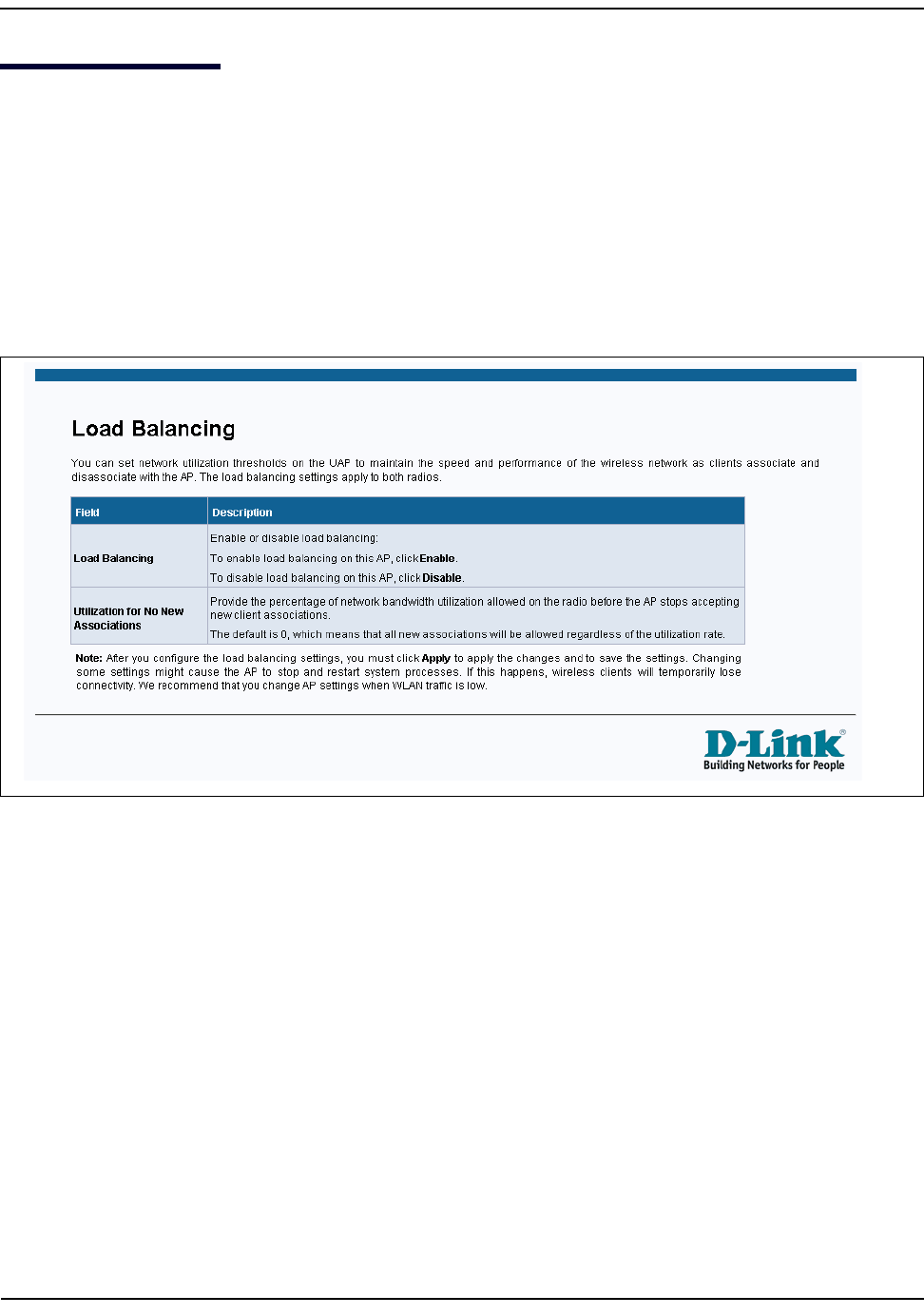
Forinformationaboutthesettingsonthecurrentpage,clicktheHelplinkontheupperrightsideofapage.
Thefollowingfigureshowsanexampleoftheonlinehelpavailablefromthelinksontheuserinterface.
Figure1:AdministratorUIOnlineHelp

GettingStarted
D-Link UnifiedAccessPointAdministrator’sGuide
November2011 Page15
UnifiedAccessPointAdministrator’sGuide
Section2:GettingStarted
TheD‐LinkDWL‐x600APunifiedaccesspoint(UAP)providescontinuous,high‐speedaccessbetweenwireless
devicesandEthernetdevices.Itisanadvanced,standards‐basedsolutionforwirelessnetworkinginbusinesses
ofanysize.TheUAPenableswirelesslocalareanetwork(WLAN)deploymentwhileprovidingstate‐of‐the‐art
wirelessnetworkingfeatures.
TheUAPcanoperateintwomodes:StandaloneModeorManagedMode.InStandaloneMode,theUAPacts
asanindividualaccesspointinthenetwork,andyoumanageitbyusingtheAdministratorWebUserInterface
(UI),command‐lineinterface(CLI),orSNMP.InManagedMode,theUAPispartoftheD‐LinkUnifiedWiredand
WirelessSystem,andyoumanageitbyusingtheD‐LinkUnifiedWirelessSwitch.IfanAPisinManagedMode,
theAdministratorWebUI,Telnet,SSH,andSNMPservicesaredisabled.
Thisdocumentdescribeshowtoperformthesetup,management,andmaintenanceoftheUAPinStandalone
Mode.ForinformationaboutconfiguringtheAPinManagedModebyusingtheD‐LinkUnifiedWirelessSwitch,
seetheUserManualfortheswitch.
BeforeyoupoweronanewUAP,reviewthefollowingsectionstocheckrequiredhardwareandsoftware
components,clientconfigurations,andcompatibilityissues.Makesureyouhaveeverythingyouneedfora
successfullaunchandtestofyourneworextendedwirelessnetwork.
TheDWL‐6600APandDWL‐8600AParedual‐radioaccesspointsandsupporttheIEEE802.11a,802.11b,
802.11g,and802.11nmodes.TheDWL‐3600APisasingle‐radioaccesspointandsupportstheIEEE802.11b,
IEEE802.11g,and802.11n(2.4GHz)modes.
Thissectioncontainsthefollowingtopics:
•“Administrator ’sComputerRequirements”
•“WirelessClientRequirements”
•“DynamicandStaticIPAddressingontheAP”
•“InstallingtheUAP”
•“BasicSettings”
•“UsingtheCLItoViewtheIPAddress”
•“ConfiguringtheEthernetSettings”
•“ConfiguringIEEE802.1XAuthentication”
•“VerifyingtheInstallation”
•“ConfiguringSecurityontheWirelessAccessPoint”
TomanagetheUAPbyusingtheWebinterfaceorbyusingtheCLIthroughTelnetorSSH,theAPneedsanIP
address.IfyouuseVLANsorIEEE802.1XAuthentication(portsecurity)onyournetwork,youmightneedto
configureadditionalsettingsontheAPbeforeitcanconnecttothenetwork.
Note:TheWLANAPisnotdesignedtofunctionasagatewaytotheInternet.ToconnectyourWLAN
tootherLANsortheInternet,youneedagatewaydevice.
Administrator’sComputerRequirements
D-Link UnifiedAccessPointAdministrator’sGuide
November2011 Page16
UnifiedAccessPointAdministrator’sGuide
Administrator’sComputerRequirements
Thefollowingtabledescribestheminimumrequirementsfortheadministrator’scomputerforconfiguration
andadministrationoftheUAPthroughaWeb‐baseduserinterface(UI).
Table2:RequirementsfortheAdministrator’sComputer
RequiredSoftwareorComponent Description
SerialorEthernetConnectiontothe
AccessPoint
Thecomputerusedtoconfigurethefirstaccesspointmustbe
connectedtotheaccesspointbyaserialcableoranEthernetcable.
WirelessConnectiontotheNetwork Afterinitialconfigurationandlaunchofthefirstaccesspointonyour
newwirelessnetwork,youcanmakesubsequentconfiguration
changesthroughtheAdministrationWebpagesusingawireless
connectiontotheinternalnetwork.Forwirelessconnectiontothe
accesspoint,youradministrationdevicewillneedWi‐Ficapability
similartothatofanywirelessclient:
Portableorbuilt‐inWi‐Ficlientadapterthatsupportsoneormoreof
theIEEE802.11modesinwhichyouplantoruntheaccesspoint.
WirelessclientsoftwareconfiguredtoassociatewiththeUAP.
WebBrowserandOperatingSystem ConfigurationandadministrationoftheUAPisprovidedthrougha
Web‐baseduserinterfacehostedontheaccesspoint.We
recommendusingoneofthefollowingsupportedWebbrowsersto
accesstheaccesspointAdministrationWebpages:
• Microsoft®InternetExplorer®version7.xor8.x(withup‐to‐date
patchlevelforeithermajorversion)
• Mozilla®Firefoxversion3.5orlater
•Safari5andlaterversions
TheadministrationWebbrowsermusthaveJavaScript™enabledto
supporttheinteractivefeaturesoftheadministrationinterface.
SecuritySettings Ensurethatsecurityisdisabledonthewirelessclientusedtoinitially
configuretheaccesspoint.
WirelessClientRequirements
D-Link UnifiedAccessPointAdministrator’sGuide
November2011 Page17
UnifiedAccessPointAdministrator’sGuide
WirelessClientRequirements
TheUAPprovideswirelessaccesstoanyclientwithaproperlyconfiguredWi‐Ficlientadapterforthe802.11
modeinwhichtheaccesspointisrunning.TheUAPsupportsmultipleclientoperatingsystems.Clientscanbe
laptopordesktopcomputers,personaldigitalassistants(PDAs),oranyotherhand‐held,portableorstationary
deviceequippedwithaWi‐Fiadapterandsupportingdrivers.
Toconnecttotheaccesspoint,wirelessclientsneedthesoftwareandhardwaredescribedinthefollowing
table.
DynamicandStaticIPAddressingontheAP
Whenyoupowerontheaccesspoint,thebuilt‐inDHCPclientsearchesforaDHCPserveronthenetworkin
ordertoobtainanIPAddressandothernetworkinformation.IftheAPdoesnotfindaDHCPserveronthe
network,theAPcontinuestouseitsdefaultStaticIPAddress(10.90.90.91)untilyoure‐assignitanewstatic
IPaddress(andspecifyastaticIPaddressingpolicy)oruntiltheAPsuccessfullyreceivesnetworkinformation
fromaDHCPserver.
TochangetheconnectiontypeandassignastaticIPaddressbyusingtheCLI,see“ConfiguringtheEthernet
Settings”onpage25or,byusingtheWebUI,see“EthernetSettings”onpage51.
Table3:RequirementsforWirelessClients
RequiredComponent Description
Wi‐FiClientAdapter Portableorbuilt‐inWi‐FiclientadapterthatsupportsoneormoreoftheIEEE
802.11modesinwhichyouplantoruntheaccesspoint.
WirelessClientSoftware Clientsoftware,suchasMicrosoftWindowsSupplicant,configuredtoassociate
withtheUAP.
ClientSecuritySettings Securityshouldbedisabledontheclientusedtodoinitialconfigurationofthe
accesspoint.
IftheSecuritymodeontheaccesspointissettoanythingotherthanplaintext,
wirelessclientswillneedtosetaprofiletotheauthenticationmodeusedbythe
accesspointandprovideavalidusernameandpassword,certificate,orsimilaruser
identityproof.SecuritymodesareStaticWEP,IEEE802.1X,WPAwithRADIUS
server,andWPA‐PSK.
Forinformationaboutconfiguringsecurityontheaccesspoint,see“VirtualAccess
PointSettings”onpage70.
Caution!IfyoudonothaveaDHCPserveronyourinternalnetwork,anddonotplantouseone,the
firstthingyoumustdoafterpoweringontheaccesspointischangetheconnectiontypefromDHCP
tostaticIP.YoucaneitherassignanewstaticIPaddresstotheAPorcontinueusingthedefault
address.WerecommendassigninganewstaticIPaddresssothatifyoubringupanotherWLANAP
onthesamenetwork,theIPaddressforeachAPwillbeunique.

DynamicandStaticIPAddressingontheAP
D-Link UnifiedAccessPointAdministrator’sGuide
November2011 Page18
UnifiedAccessPointAdministrator’sGuide
RecoveringanIPAddress
Ifyouexperiencetroublecommunicatingwiththeaccesspoint,youcanrecoverastaticIPaddressbyresetting
theAPconfigurationtothefactorydefaults(see“ResettingtheFactoryDefaultConfiguration”onpage120),
oryoucangetadynamicallyassignedaddressbyconnectingtheAPtoanetworkthathasaDHCPserver.
DiscoveringaDynamicallyAssignedIPAddress
IfyouhaveaccesstotheDHCPserveronyournetworkandknowtheMACaddressofyourAP,youcanview
thenewIPaddressassociatedwiththeMACaddressoftheAP.
IfyoudonothaveaccesstotheDHCPserverthatassignedtheIPaddresstotheAPordonotknowtheMAC
addressoftheAP,youmightneedtousetheCLItofindoutwhatthenewIPaddressis.Forinformationabout
howtodiscoveradynamicallyassignedIPaddress,see“UsingtheCLItoViewtheIPAddress”onpage24.
InstallingtheUAP
D-Link UnifiedAccessPointAdministrator’sGuide
November2011 Page19
UnifiedAccessPointAdministrator’sGuide
InstallingtheUAP
ToaccesstheAdministrationWebUI,youentertheIPaddressoftheAPintoaWebbrowser.Youcanusethe
defaultIPaddressoftheAP(10.90.90.91)tologontotheAPandassignastaticIPaddress,oryoucanusea
DHCPserveronyounetworktoassignnetworkinformationtotheAP.TheDHCPclientontheAPisenabledby
default.
ToinstalltheUAP,usethefollowingsteps:
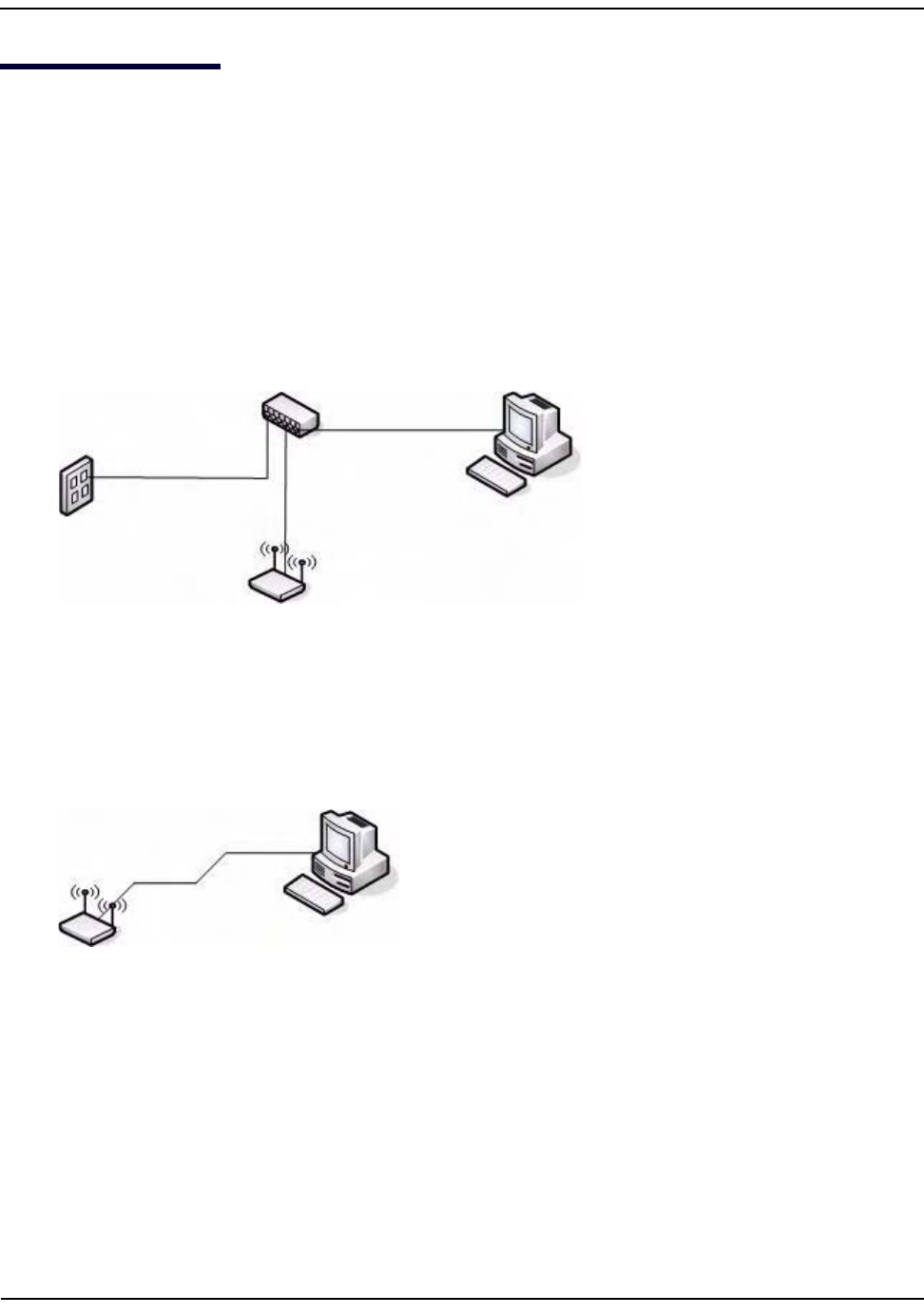
1. ConnecttheAPtoanadministrativePCbyusingaLANconnectionoradirect‐cableconnection.
•TouseaLANconnection,connectoneendofanEthernetcabletothenetworkportontheaccesspoint
andtheotherendtothesamehubwhereyourPCisconnected,asshowninthefollowingfigure.
Thehuborswitchyouusemustpermitbroadcastsignalsfromtheaccesspointtoreachallotherdevices
onthenetwork.
•Touseadirect‐cableconnection,connectoneendofanEthernetstraight‐throughorcrossovercableto
thenetworkportontheaccesspointandtheotherendofthecabletotheEthernetportonthePC,as
showninthefollowingfigure.YoucanalsouseaserialcabletoconnecttheserialportontheAPtoa
serialportontheadministrativecomputer.
ForinitialconfigurationwithadirectEthernetconnectionandnoDHCPserver,besuretosetyourPCtoa
staticIPaddressinthesamesubnetasthedefaultIPaddressontheaccesspoint.(ThedefaultIPaddress
fortheaccesspointis10.90.90.91.)
Ifyouusethismethod,youwillneedtoreconfigurethecablingforsubsequentstartupanddeploymentof
theaccesspointsothattheaccesspointisnolongerconnecteddirectlytothePCbutinsteadisconnected
totheLAN(eitherbyusingahubordirectly).
InstallingtheUAP
D-Link UnifiedAccessPointAdministrator’sGuide
November2011 Page20
UnifiedAccessPointAdministrator’sGuide
2. Connectthepoweradaptertothepowerportonthebackoftheaccesspoint,andthenplugtheotherend
ofthepowercordintoapoweroutlet.
3. UseyourWebbrowsertologontotheUAPAdministrationWebpages.
–IftheAPdidnotacquireanIPaddressfromaDHCPserveronyournetwork,enter10.90.90.91inthe
addressfieldofyourbrowser,whichisthedefaultIPaddressoftheAP.
–IfyouusedaDHCPserveronyournetworktoautomaticallyconfigurenetworkinformationfortheAP,
enterthenewIPaddressoftheAPintotheWebbrowser.
–IfyouusedaDHCPserverandyoudonotknowthenewIPaddressoftheAP,usethefollowing
procedurestoobtaintheinformation:
a. ConnectaserialcablefromtheadministrativecomputertotheAPanduseaterminalemulation
programtoaccessthecommand‐lineinterface(CLI).
b. Attheloginprompt,enteradminfortheusernameandadminforthepassword.Atthecommand
prompt,entergetmanagement.
–ThecommandoutputdisplaystheIPaddressoftheAP.Enterthisaddressintheaddressfieldofyour
browser.ForamoredetailedexplanationabouthowtologontotheCLIbyusingtheconsoleport,see
“UsingtheCLItoViewtheIPAddress”onpage24.
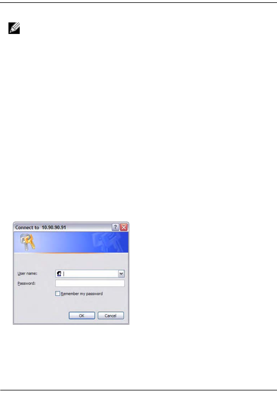
4. Whenprompted,enteradminfortheusernameandadminforthepassword,thenclickOK.
Note:Itispossibletodetectaccesspointsonthenetworkwithawirelessconnection.However,
westronglyadviseagainstusingthismethod.Inmostenvironmentsyoumayhavenowayof
knowingwhetheryouareactuallyconnectingtotheintendedAP.Also,manyoftheinitial
configurationchangesrequiredwillcauseyoutoloseconnectivitywiththeAPoverawireless
connection.
InstallingtheUAP
D-Link UnifiedAccessPointAdministrator’sGuide
November2011 Page21
UnifiedAccessPointAdministrator’sGuide
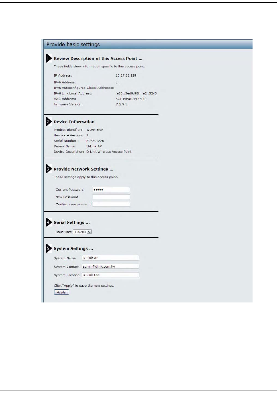
Whenyoufirstlogin,theBasicSettingspageforUAPadministrationisdisplayed,asthefollowingfigure
shows.
5. VerifythesettingsontheBasicSettingspage.
• Reviewaccesspointdescriptionandprovideanewadministratorpasswordfortheaccesspointifyou
donotwanttousethedefaultpassword,whichisadmin.
•ClicktheApplybuttontoactivatethewirelessnetworkwiththesenewsettings.

BasicSettings
D-Link UnifiedAccessPointAdministrator’sGuide
November2011 Page22
UnifiedAccessPointAdministrator’sGuide
ForinformationaboutthefieldsandconfigurationoptionsontheBasicSettingspage,see“BasicSettings”
onpage22.
6. IfyoudonothaveaDHCPserveronthemanagementnetworkanddonotplantouseone,youmustchange
theConnectionTypefromDHCPtoStaticIP.
YoucaneitherassignanewStaticIPaddresstotheAPorcontinueusingthedefaultaddress.We
recommendassigninganewStaticIPaddresssothatifyoubringupanotherUAPonthesamenetwork,
theIPaddressforeachAPwillbeunique.TochangetheconnectiontypeandassignastaticIPaddress,see
“ConfiguringtheEthernetSettings”onpage25(CLI)or“EthernetSettings”onpage51(Web).
7. IfyournetworkusesVLANs,youmightneedtoconfigurethemanagementVLANIDoruntaggedVLANID
ontheUAPinorderforittoworkwithyournetwork.
ForinformationabouthowtoconfigureVLANinformation,see“ConfiguringtheEthernetSettings”on
page25(CLI)or“EthernetSettings”onpage51(Web).
8. IfyournetworkusesIEEE802.1Xportsecurityfornetworkaccesscontrol,youmustconfigurethe802.1X
supplicantinformationontheAP.
Forinformationabouthowtoconfigurethe802.1Xusernameandpassword,see“ConfiguringIEEE802.1X
Authentication”onpage27.
BasicSettings
FromtheBasicSettingspage,youcanviewvariousinformationabouttheUAP,includingIPandMACaddress
information,andconfiguretheadministratorpasswordfortheUAP.Table4describesthefieldsand
configurationoptionsontheBasicSettingspage.
Note:ThechangesyoumakearenotsavedorapplieduntilyouclickApply.Changingsomeaccess
pointsettingsmightcausetheAPtostopandrestartsystemprocesses.Ifthishappens,wireless
clientswilltemporarilyloseconnectivity.Werecommendthatyouchangeaccesspointsettings
whenWLANtrafficislow.
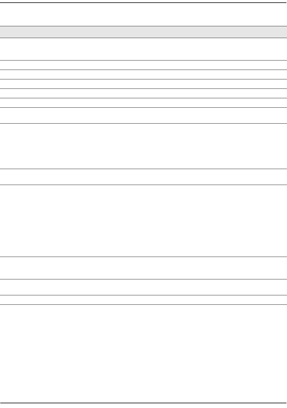
Table4:BasicSettingsPage
FieldDescription
IPAddress ShowstheIPaddressassignedtotheAP.Thisfieldisnoteditableonthispagebecause
theIPaddressisalreadyassigned(eitherbyDHCP,orstaticallythroughtheEthernet
Settingspage).
IPv6Address ShowstheIPv6addressassignedtotheAP.Thisfieldisnoteditableonthispagebecause
theIPaddressisalreadyassigned(eitherbyDHCPv6,orstaticallythroughtheEthernet
Settingspage).
IPv6LinkLocal
Address
ShowstheIPv6LinkLocaladdress,whichistheIPv6addressusedbythelocalphysical
link.ThelinklocaladdressisnotconfigurableandisassignedbyusingtheIPv6Neighbor
Discoveryprocess.
MACAddress ShowstheMACaddressoftheAP.TheaddressshownhereistheMACaddress
associatedwiththemanagementinterface.ThisistheaddressbywhichtheAPisknown
externallytoothernetworks.
BasicSettings
D-Link UnifiedAccessPointAdministrator’sGuide
November2011 Page23
UnifiedAccessPointAdministrator’sGuide
FirmwareVersion ShowsversioninformationaboutthefirmwarecurrentlyinstalledontheAP.Asnew
versionsoftheWLANAPfirmwarebecomeavailable,youcanupgradethefirmwareon
yourAPs.
ProductIdentifier IdentifiestheAPhardwaremodel.
HardwareVersion IdentifiestheAPhardwareversion.
SerialNumber ShowstheAPserialnumber.
DeviceName Genericnametoidentifythetypeofhardware.
DeviceDescription Providesinformationabouttheproducthardware.
CurrentPassword Enterthecurrentadministratorpassword.Youmustcorrectlyenterthecurrentpassword
beforeyouareabletochangeit.
NewPassword Enteranewadministratorpassword.Thecharactersyouenteraredisplayedasbullet
characterstopreventothersfromseeingyourpasswordasyoutype.
Theadministratorpasswordmustbeanalphanumericstringofupto8characters.Donot
usespecialcharactersorspaces.
Note:Asanimmediatefirststepinsecuringyourwirelessnetwork,werecommendthat
youchangetheadministratorpasswordfromthedefault.
ConfirmNew
Password
Re‐enterthenewadministratorpasswordtoconfirmthatyoutypeditasintended.
BaudRate Selectabaudratefortheserialportconnection.ThebaudrateontheAPmustmatch
thebaudrateontheterminalorterminalemulatortoconnecttotheAPcommand‐line
interface(CLI)byusingaserial(console)connection.
Thefollowingbaudratesareavailable:
• 9600
•19200
• 38400
•57600
• 115200
SystemName EnteranamefortheAP.ThisnameappearsonlyontheBasicSettingspageandisaname
toidentifytheAPtotheadministrator.Useupto64alphanumericcharacters,for
exampleMyAP
.
SystemContact Enterthename,e‐mailaddress,orphonenumberofthepersontocontactregarding
issuesrelatedtotheAP.
SystemLocation EnterthephysicallocationoftheAP,forexampleConferenceRoomA.
Table4:BasicSettingsPage(Cont.)
FieldDescription

UsingtheCLItoViewtheIPAddress
D-Link UnifiedAccessPointAdministrator’sGuide
November2011 Page24
UnifiedAccessPointAdministrator’sGuide
ConnectingtotheAPWebInterfacebyUsingtheIPv6Address
ToconnecttotheAPbyusingtheIPv6globaladdressorIPv6linklocaladdress,youmustentertheAPaddress
intoyourbrowserinaspecialformat.
ToconnecttoanIPv6globaladdress,addsquarebracketsaroundtheIPv6address.Forexample,iftheAP
globalIPv6addressis2520::230:abff:fe00:2420,typethefollowingaddressintotheIE7addressfield:http://
[2520::230:abff:fe00:2420].
ToconnecttotheiPv6linklocaladdress,replacethecolons(:)withhyphens(‐),addtheinterfacenumber
precededwithan"s,"thenadd".ipv6‐literal.net."Forexample,iftheAPlinklocaladdressis
fe80::230:abff:fe00:2420,andtheWindowsinterfaceisdefinedas"%6,"typethefollowingaddressintothe
IE7addressfield:http://fe80‐‐230‐abff‐fe00‐2420s6.ipv6‐literal.net.
UsingtheCLItoViewtheIPAddress
TheDHCPclientontheUAPisenabledbydefault.IfyouconnecttheUAPtoanetworkwithaDHCPserver,the
APautomaticallyacquiresanIPaddress.TomanagetheUAPbyusingtheAdministratorUI,youmustenterthe
IPaddressoftheaccesspointintoaWebbrowser.
IfaDHCPserveronyournetworkassignsanIPaddresstotheUAP,andyoudonotknowtheIPaddress,use
thefollowingstepstoviewtheIPaddressoftheUAP:
1. Usinganull‐modemcable,connectaVT100/ANSIterminaloraworkstationtotheconsole(serial)port.
IfyouattachedaPC,Apple,orUNIXworkstation,startaterminal‐emulationprogram,suchas
HyperTerminalorTeraTerm.
2. Configuretheterminal‐emulationprogramtousethefollowingsettings:
•Baudrate:115200bps
•Databits:8
•Parity:none
•Stopbit:1
• Flowcontrol:none
3. Pressthereturnkey,andaloginpromptshouldappear.
Theloginnameisadmin.Thedefaultpasswordisadmin.Afterasuccessfullogin,thescreenshowsthe
(AccessPointName)#prompt.
Note:ThefollowinginstructionsandexamplesworkwithMicrosoftInternetExplorer7(IE7)and
mightnotworkwithotherbrowsers.
ConfiguringtheEthernetSettings
D-Link UnifiedAccessPointAdministrator’sGuide
November2011 Page25
UnifiedAccessPointAdministrator’sGuide
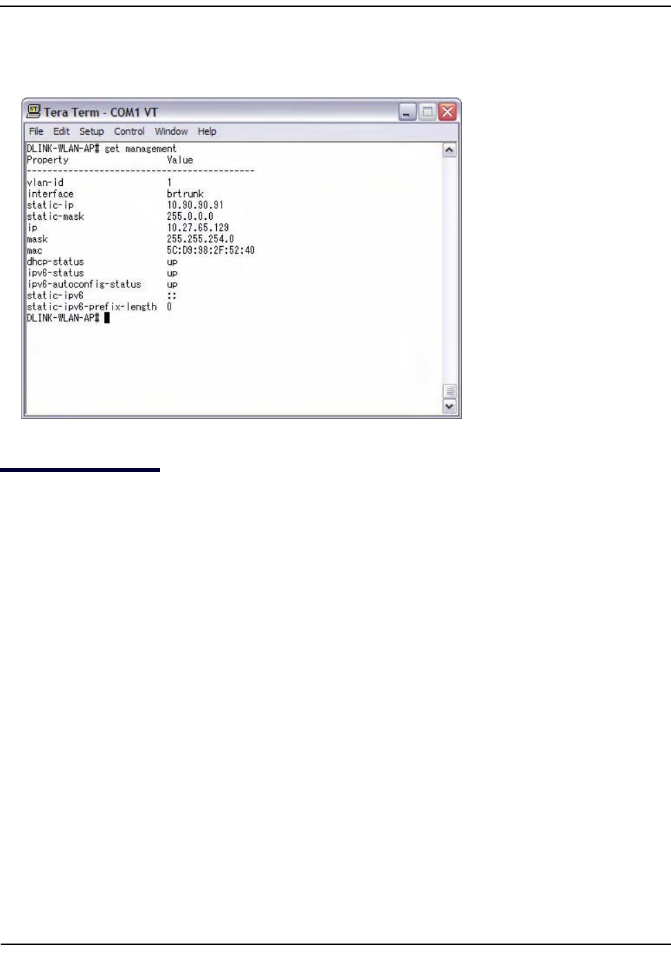
4. Attheloginprompt,entergetmanagement.
Informationsimilartothefollowingprintstothescreen.
ConfiguringtheEthernetSettings
ThedefaultEthernetsettings,whichincludeDHCPandVLANinformation,mightnotworkforallnetworks.
Bydefault,theDHCPclientontheUAPautomaticallybroadcastsrequestsfornetworkinformation.Ifyouwant
touseastaticIPaddress,youmustdisabletheDHCPclientandmanuallyconfiguretheIPaddressandother
networkinformation.
ThemanagementVLANisVLAN1bydefault.ThisVLANisalsothedefaultuntaggedVLAN.Ifyoualreadyhave
amanagementVLANconfiguredonyournetworkwithadifferentVLANID,youmustchangetheVLANIDof
themanagementVLANontheaccesspoint.
ForinformationaboutusingtheWebinterfacetoconfiguretheEthernetsettings,see“EthernetSettings”on
page51.YoucanalsousetheCLItoconfiguretheEthernetsettings,whichthefollowingsectiondescribes.

ConfiguringtheEthernetSettings
D-Link UnifiedAccessPointAdministrator’sGuide
November2011 Page26
UnifiedAccessPointAdministrator’sGuide
UsingtheCLItoConfigureEthernetSettings
UsethecommandsshowninthefollowingtabletoviewandsetvaluesfortheEthernet(wired)interface.For
moreinformationabouteachsetting,seethedescriptionforthefieldinTable17onpage52.
Inthefollowingexample,theadministratorusestheCLItosetthemanagementVLANIDto123andtodisable
theuntaggedVLANsothatalltrafficistaggedwithaVLANID.
D‐Link‐WLAN‐AP#setmanagementvlan‐id123
D‐Link‐WLAN‐AP#setuntagged‐vlanstatusdown
Table5:CLICommandsforEthernetSetting
Action Command
GettheDNSName gethostid
SettheDNSName sethostid<host_name>
Forexample:
sethostidvicky‐ap
GetCurrentSettingsfortheEthernet(Wired)Internal
Interface
getmanagement
SetthemanagementVLANID setmanagementvlan‐id<1‐4094>
ViewuntaggedVLANinformation getuntagged‐vlan
EnabletheuntaggedVLAN setuntagged‐vlanstatusup
DisabletheuntaggedVLAN setuntagged‐vlanstatusdown
SettheuntaggedVLANID setuntagged‐vlanvlan‐id<1‐4094>
Viewtheconnectiontype getmanagementdhcp‐status
UseDHCPastheconnectiontype setmanagementdhcp‐statusup
UseaStaticIPastheconnectiontype setmanagementdhcp‐statusdown
SettheStaticIPaddress setmanagementstatic‐ip<ip_address>
Forexample:
setmanagementstatic‐ip10.10.12.221
SetaSubnetMask setmanagementstatic‐mask<netmask>
Forexample:
setmanagementstatic‐mask255.255.255.0
SettheDefaultGateway setstatic‐ip‐routegateway<ip_address>
Forexample:
setstatic‐ip‐routegateway10.10.12.1
ViewtheDNSNameservermodeDynamic=up
Manual=down
gethostdns‐via‐dhcp
SetDNSNameserverstoUseStaticIPAddresses(Dynamic
toManualMode)
sethostdns‐via‐dhcpdown
sethoststatic‐dns‐1
<ip_address>
sethoststatic‐dns‐2
<ip_address>
Forexample:
sethoststatic‐dns‐1192.168.23.45
SetDNSNameserverstoUseDHCPIPAddressing(Manual
toDynamicMode)
sethostdns‐via‐dhcpup

ConfiguringIEEE802.1XAuthentication
D-Link UnifiedAccessPointAdministrator’sGuide
November2011 Page27
UnifiedAccessPointAdministrator’sGuide
D‐Link‐WLAN‐AP#getmanagement
PropertyValue
‐‐‐‐‐‐‐‐‐‐‐‐‐‐‐‐‐‐‐‐‐‐‐‐‐‐‐‐‐‐‐‐‐‐‐‐‐‐‐‐‐‐‐‐
vlan‐id123
interfacebrtrunk
static‐ip10.90.90.91
static‐mask255.0.0.0
ip10.90.90.91
mask255.0.0.0
mac5C:D9:98:2F:52:40
dhcp‐statusup
ipv6‐statusup
ipv6‐autoconfig‐statusup
static‐ipv6::
static‐ipv6‐prefix‐length0
D‐Link‐WLAN‐AP#getuntagged‐vlan
PropertyValue
‐‐‐‐‐‐‐‐‐‐‐‐‐‐‐
vlan‐id1
statusdown
D‐Link‐WLAN‐AP#
ConfiguringIEEE802.1XAuthentication
OnnetworksthatuseIEEE802.1X,port‐basednetworkaccesscontrol,asupplicant(client)cannotgainaccess
tothenetworkuntilthe802.1Xauthenticatorgrantsaccess.Ifyournetworkuses802.1X,youmustconfigure
802.1XauthenticationinformationthattheAPcansupplytotheauthenticator.
IfyournetworkusesIEEE802.1Xsee“Configuring802.1XAuthentication”onpage92forinformationabout
howtoconfigure802.1XbyusingtheWebinterface.
UsingtheCLItoConfigure802.1XAuthenticationInformation
Thefollowingtableshowsthecommandsusedtoconfigurethe802.1XsupplicantinformationusingtheCLI.
Table6:CLICommandsforthe802.1XSupplicant
Action Command
View802.1Xsupplicantsettings getdot1x‐supplicant
Enable802.1Xsupplicant setdot1x‐supplicantstatusup
Disable802.1Xsupplicant setdot1x‐supplicantstatusdown
Setthe802.1Xusername setdot1x‐supplicantuser<name>
Setthe802.1spassword setdot1x‐supplicantpassword<password>

VerifyingtheInstallation
D-Link UnifiedAccessPointAdministrator’sGuide
November2011 Page28
UnifiedAccessPointAdministrator’sGuide
Inthefollowingexample,theadministratorenablesthe802.1XsupplicantandsetstheusernametowlanAP
andthepasswordtotest1234.
D‐Link‐WLAN‐AP#setdot1x‐supplicantstatusup
D‐Link‐WLAN‐AP#setdot1x‐supplicantuserwlanAP
D‐Link‐WLAN‐AP#setdot1x‐supplicantpasswordtest1234
D‐Link‐WLAN‐AP#getdot1x‐supplicant
PropertyValue
‐‐‐‐‐‐‐‐‐‐‐‐‐‐‐‐
statusup
userwlanAP
VerifyingtheInstallation
MakesuretheaccesspointisconnectedtotheLANandassociatesomewirelessclientswiththenetwork.Once
youhavetestedthebasicsofyourwirelessnetwork,youcanenablemoresecurityandfine‐tunetheAPby
modifyingadvancedconfigurationfeatures.
1. ConnecttheaccesspointtotheLAN.
•IfyouconfiguredtheaccesspointandadministratorPCbyconnectingbothintoanetworkhub,then
youraccesspointisalreadyconnectedtotheLAN.Thenextstepistotestsomewirelessclients.
•Ifyouconfiguredtheaccesspointbyusingadirectcableconnectionfromyourcomputertotheaccess
point,dothefollowingprocedures:
a. Disconnectthecablefromthecomputerandtheaccesspoint.
b. ConnectanEthernetcablefromtheaccesspointtotheLAN.
c. ConnectyourcomputertotheLANbyusinganEthernetcableorawirelesscard.
2. TestLANconnectivitywithwirelessclients.
TesttheUAPbytryingtodetectitandassociatewithitfromsomewirelessclientdevices.Forinformation
aboutrequirementsfortheseclients,see“WirelessClientRequirements”onpage17.
3. Secureandconfiguretheaccesspointbyusingadvancedfeatures.
OncethewirelessnetworkisupandyoucanconnecttotheAPwithsomewirelessclients,youcanaddin
layersofsecurity,createmultiplevirtualaccesspoints(VAPs),andconfigureperformancesettings.
Bydefault,nosecurityisinplaceontheaccesspoint,soanywirelessclientcanassociatewithitandaccess
yourLAN.Animportantnextstepistoconfiguresecurity,asdescribedin“VirtualAccessPointSettings”on
page70.
Note:TheWLANAPisnotdesignedformultiple,simultaneousconfigurationchanges.Ifmorethan
oneadministratorisloggedontotheAdministrationWebpagesandmakingchangestothe
configuration,thereisnoguaranteethatallconfigurationchangesspecifiedbymultipleuserswill
beapplied.

ConfiguringSecurityontheWirelessAccessPoint
D-Link UnifiedAccessPointAdministrator’sGuide
November2011 Page29
UnifiedAccessPointAdministrator’sGuide
ConfiguringSecurityontheWirelessAccessPoint
Youconfiguresecurewirelessclientaccessbyconfiguringsecurityforeachvirtualaccesspoint(VAP)thatyou
enable.Youcanconfigureupto16VAPsperradiothatsimulatemultipleAPsinonephysicalaccesspoint.By
default,onlyoneVAPisenabled.ForeachVAP,youcanconfigureauniquesecuritymodetocontrolwireless
clientaccess.
Eachradiohas16VAPs,withVAPIDsfrom0‐15.Bydefault,onlyVAP0oneachradioisenabled.VAP0hasthe
followingdefaultsettings:
• VLANID:1
•BroadcastSSID:Enabled
• SSID:dlink1
•Security:None
•MACAuthenticationType:None
• RedirectMode:None
AllotherVAPsaredisabledbydefault.ThedefaultSSIDforVAPs1–15is"dlinkx"wherexistheVAPID.
TopreventunauthorizedaccesstotheUAP,werecommendthatyouselectandconfigureasecurityoption
otherthanNoneforthedefaultVAPandforeachVAPthatyouenable.
ForinformationabouthowtoconfigurethesecuritysettingsoneachVAP,see“VirtualAccessPointSettings”
onpage70.

ViewingAccessPointStatus
D-Link UnifiedAccessPointAdministrator’sGuide
November2011 Page30
UnifiedAccessPointAdministrator’sGuide
Section3:ViewingAccessPointStatus
ThissectiondescribestheinformationyoucanviewfromthetabsundertheStatusheadingonthe
AdministrationWebUI.Thissectioncontainsthefollowingsubsections:
•“ViewingInterfaceStatus”
•“ViewingEvents”
•“ViewingTransmitandReceiveStatistics”
•“ViewingAssociatedWirelessClientInformation”
•“ViewingTSPECClientAssociations”
•“ViewingRogueAPDetection”
•“ViewingManagedAPDHCPInformation”
•“ViewingTSPECStatusandStatisticsInformation”
•“ViewingTSPECAPStatisticsInformation”
•“ViewingRadioStatisticsInformation”
•“ViewingEmailAlertOperationalStatus”
Note:Theweb‐basedUIimagesinthissectionshowtheDWL‐8600APadministrationpages.Pages
fortheDWL‐3600APwilldisplayinformationforoneradioonly.
ViewingInterfaceStatus
D-Link UnifiedAccessPointAdministrator’sGuide
November2011 Page31
UnifiedAccessPointAdministrator’sGuide
ViewingInterfaceStatus
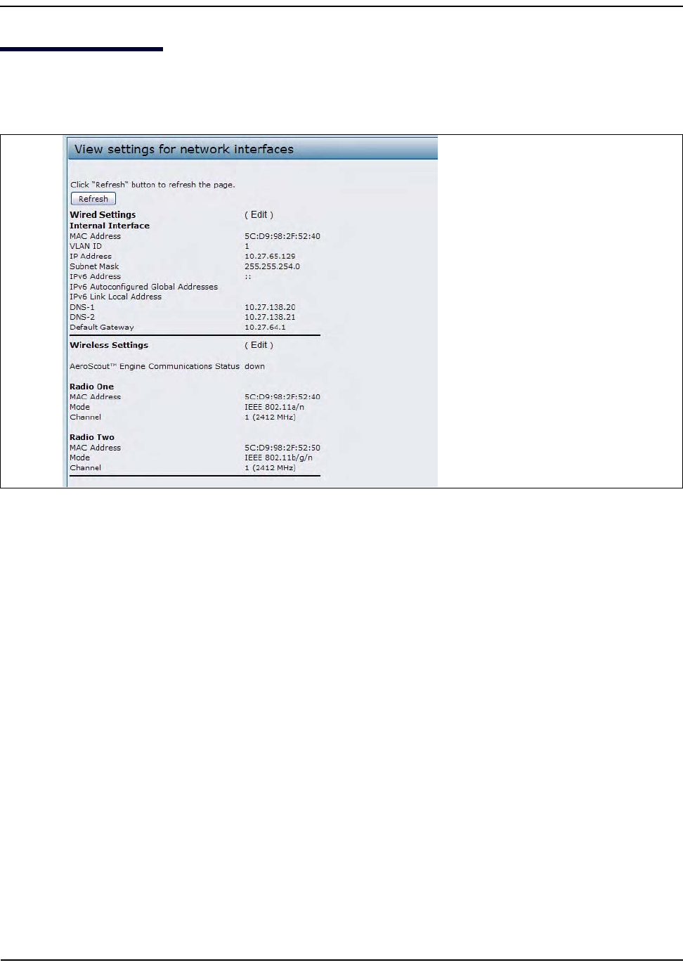
TomonitorEthernetLAN(wired)andwirelessLAN(WLAN)settings,clicktheInterfacestab.
Figure2:ViewingInterfaceStatus
ThispagedisplaysthecurrentsettingsoftheUAP.ItdisplaystheWiredSettingsandtheWirelessSettings.
WiredSettings(InternalInterface)
TheInternalinterfaceincludestheEthernetMACAddress,ManagementVLANID,IPAddress(IPv4andIPv6),
SubnetMask,andDNSinformation.Tochangeanyofthesesettings,clicktheEditlink.AfteryouclickEdit,you
areredirectedtotheEthernetSettingspage.
Forinformationaboutconfiguringthesesettings,see“ConfiguringtheEthernetSettings”onpage25.
WirelessSettings
TheRadioInterfaceincludestheAeroScout™EngineCommunicationstatus,RadioModeandChannel.The
WirelessSettingssectionalsoshowstheMACaddress(read‐only)associatedwitheachradiointerface.
TochangetheRadioModeorChannelsettings,clicktheEditlink.AfteryouclickEdit,youareredirectedtothe
ModifyWirelessSettingspage.
Forinformationaboutconfiguringthesesettings,see“WirelessSettings”onpage54and“ModifyingRadio
Settings”onpage58.
ViewingEvents
D-Link UnifiedAccessPointAdministrator’sGuide
November2011 Page32
UnifiedAccessPointAdministrator’sGuide
ViewingEvents
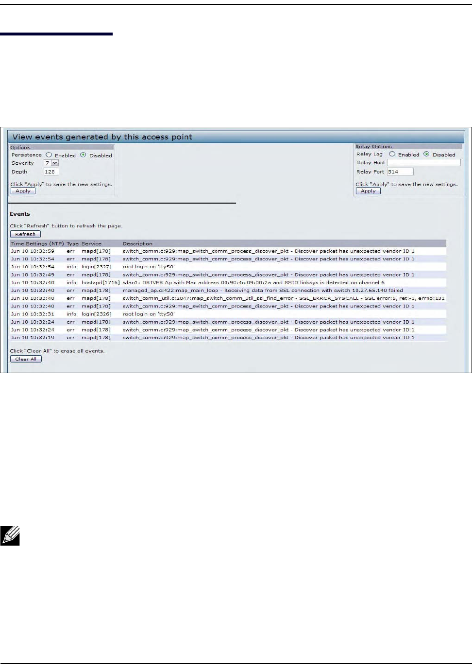
TheEventspageshowsreal‐timesystemeventsontheAPsuchaswirelessclientsassociatingwiththeAPand
beingauthenticated.
Toviewsystemevents,clicktheEventstab.
Figure3:ViewingEvents
FromtheEventspage,youcanperformthefollowingtasks:
• Viewthemostrecent,high‐leveleventsgeneratedbythisAP
.
• Enableandconfigurepersistentloggingtowritesystemeventlogstonon‐volatilememorysothatthe
eventsarenoterasedwhenthesystemreboots.
•SetaSeverityLeveltodeterminewhatcategoryoflogmessagesaredisplayed.
•SetDepthtodeterminehowmanylogmessagesaredisplayedintheEventlog.
• EnablearemotelogrelayhosttocaptureallsystemeventsanderrorsinaKernelLog.
ConfiguringPersistentLoggingOptions
Ifthesystemunexpectedlyreboots,logmessagescanbeusefultodiagnosethecause.However,logmessages
areerasedwhenthesystemrebootsunlessyouenablepersistentlogging.
Note:TheAPacquiresitsdateandtimeinformationusingthenetworktimeprotocol(NTP).Thisdata
isreportedinUTCformat(alsoknownasGreenwichMeanTime).Youneedtoconvertthereported
timetoyourlocaltime.Forinformationonsettingthenetworktimeprotocol,see“”onpage106.
ViewingEvents
D-Link UnifiedAccessPointAdministrator’sGuide
November2011 Page33
UnifiedAccessPointAdministrator’sGuide
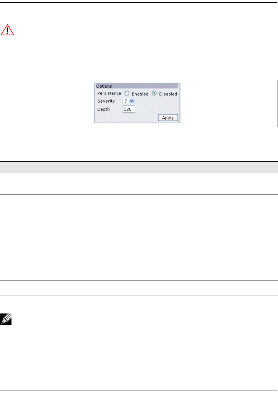
ToconfigurepersistentloggingontheEventspage,setthepersistence,severity,anddepthoptionsas
describedinTable7,andthenclickApply.
Figure4:PersistentLoggingOptions
Caution!Enablingpersistentloggingcanwearouttheflash(non‐volatile)memoryanddegrade
networkperformance.Youshouldonlyenablepersistentloggingtodebugaproblem.Makesureyou
disablepersistentloggingafteryoufinishdebuggingtheproblem.
Table7:LoggingOptions
Field Description
Persistence ChooseEnabledtosavesystemlogstonon‐volatilememorysothatthelogsarenoterased
whentheAPreboots.ChooseDisabledtosavesystemlogstovolatilememory.Logsin
volatilememoryaredeletedwhenthesystemreboots.
Severity Specifytheseveritylevelofthelogmessagestowritetonon‐volatilememory.Forexample,
ifyouspecify2,critical,alert,andemergencylogsarewrittentonon‐volatilememory.Error
messageswithaseveritylevelof3–7arewrittentovolatilememory.
•0—emergency
•1—alert
•2—critical
•3—error
•4—warning
•5—notice
•6—info
•7—debug
Depth Youcanstoreupto128messagesinnon‐volatilememory.Oncethenumberyouconfigure
inthisfieldisreached,theoldestlogeventisoverwrittenbythenewlogevent.
Note:Toapplyyourchanges,clickApply.ChangingsomesettingsmightcausetheAPtostopand
restartsystemprocesses.Ifthishappens,wirelessclientswilltemporarilyloseconnectivity.We
recommendthatyouchangeAPsettingswhenWLANtrafficislow.
ViewingEvents
D-Link UnifiedAccessPointAdministrator’sGuide
November2011 Page34
UnifiedAccessPointAdministrator’sGuide
ConfiguringtheLogRelayHostforKernelMessages
TheKernelLogisacomprehensivelistofsystemevents(shownintheSystemLog)andkernelmessagessuch
aserrorconditions,likedroppingframes.
YoucannotviewkernellogmessagesdirectlyfromtheAdministrationWebUIforanAP.Youmustfirstsetup
aremoteserverrunningasyslogprocessandactingasasysloglogrelayhostonyournetwork.Then,youcan
configuretheUAPtosendsyslogmessagestotheremoteserver.
RemotelogservercollectionforAPsyslogmessagesprovidesthefollowingfeatures:
• AllowsaggregationofsyslogmessagesfrommultipleAPs
•StoresalongerhistoryofmessagesthankeptonasingleAP
•Triggersscriptedmanagementoperationsandalerts
TouseKernelLogrelaying,youmustconfigurearemoteservertoreceivethesyslogmessages.Theprocedure
toconfigurearemoteloghostdependsonthetypeofsystemyouuseastheremotehost.
EnablingorDisablingtheLogRelayHostontheEventsPage
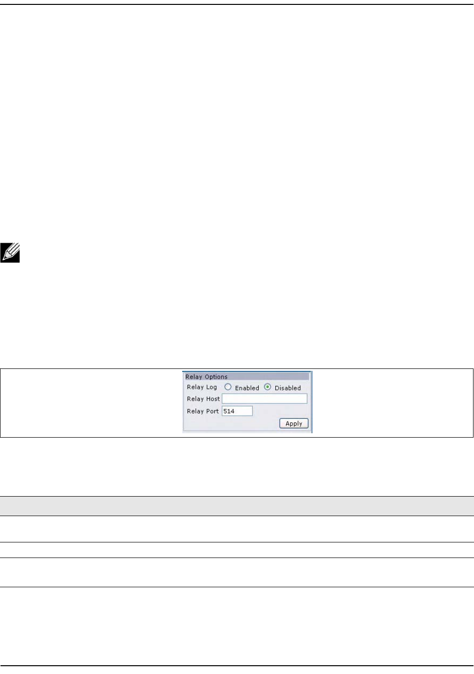
ToenableandconfigureLogRelayingontheEventspage,settheLogRelayoptionsasdescribedinthe
followingtable,andthenclickApply.
Figure5:LogRelayHost
Note:Thesyslogprocesswilldefaulttouseport514.Werecommendkeepingthisdefaultport.
However;Ifyouchoosetoreconfigurethelogport,makesurethattheportnumberyouassignto
syslogisnotbeingusedbyanotherprocess.
Table8:LogRelayHost
Field Description
RelayLog SelectEnabledtoallowtheUAPtosendlogmessagestoaremotehost.Select
Disabledtokeepalllogmessagesonthelocalsystem.
RelayHost SpecifytheIPAddressorDNSnameoftheremotelogserver.
RelayPort SpecifythePortnumberforthesyslogprocessontheRelayHost.
Thedefaultportis514.

ViewingEvents
D-Link UnifiedAccessPointAdministrator’sGuide
November2011 Page35
UnifiedAccessPointAdministrator’sGuide
IfyouenabledtheLogRelayHost,clickingApplywillactivateremotelogging.TheAPwillsenditskernel
messagesreal‐timefordisplaytotheremotelogservermonitor,aspecifiedkernellogfile,orotherstorage,
dependingonhowyouconfiguredtheLogRelayHost.
IfyoudisabledtheLogRelayHost,clickingApplywilldisableremotelogging.
Note:Toapplyyourchanges,clickApply.ChangingsomesettingsmightcausetheAPtostopand
restartsystemprocesses.Ifthishappens,wirelessclientswilltemporarilyloseconnectivity.We
recommendthatyouchangeAPsettingswhenWLANtrafficislow.
ViewingTransmitandReceiveStatistics
D-Link UnifiedAccessPointAdministrator’sGuide
November2011 Page36
UnifiedAccessPointAdministrator’sGuide
ViewingTransmitandReceiveStatistics
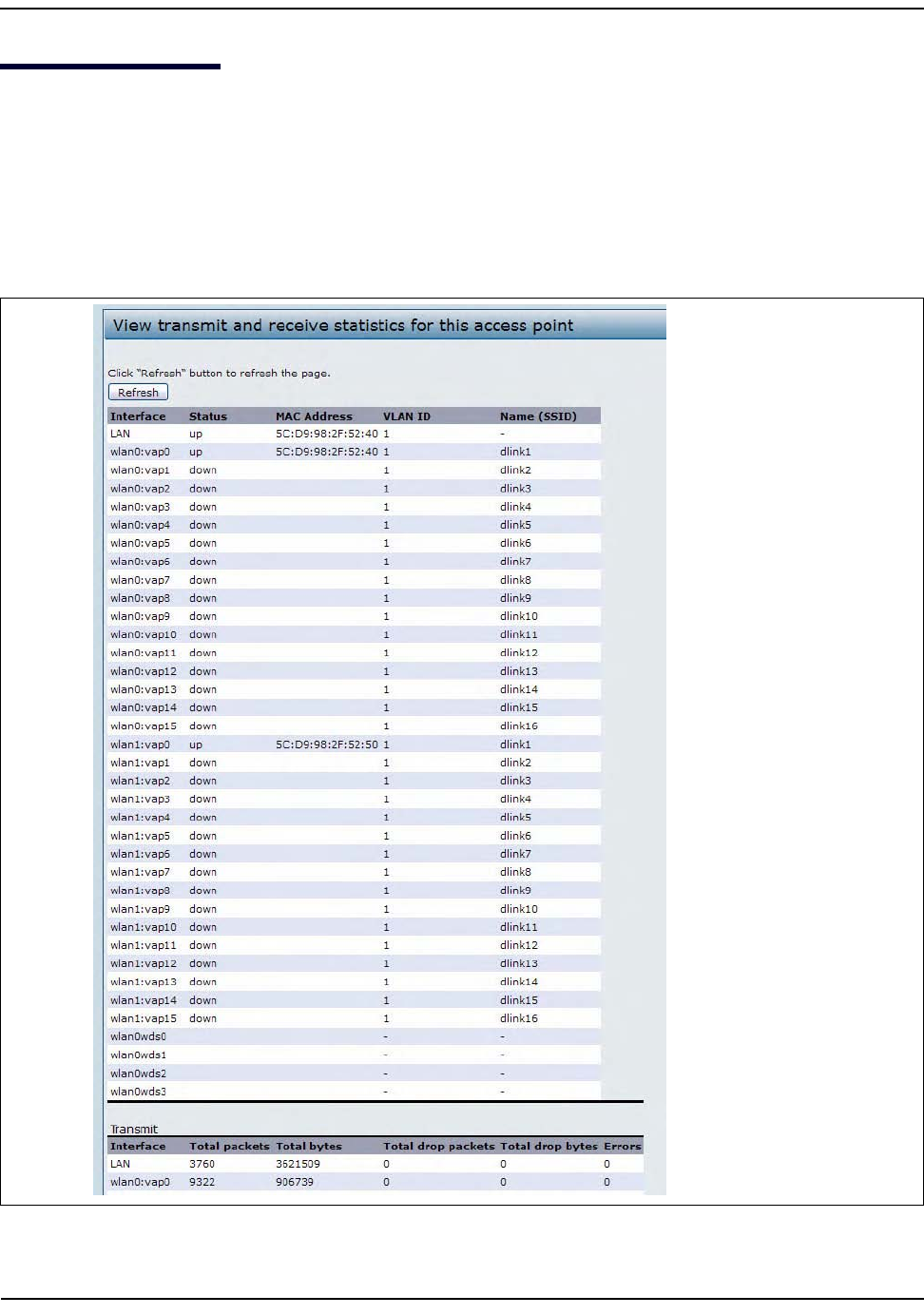
TheTransmit/ReceivepageprovidessomebasicinformationaboutthecurrentAPandareal‐timedisplayof
thetransmitandreceivestatisticsfortheEthernetinterfaceontheAPandfortheVAPsonallsupportedradio
interfaces.AlltransmitandreceivestatisticsshownaretotalssincetheAPwaslaststarted.Ifyourebootthe
AP,thesefiguresindicatetransmitandreceivetotalssincethereboot.
ToviewtransmitandreceivestatisticsfortheAP,clicktheTransmit/Receivepage.
Figure6:ViewingTrafficStatistics
ViewingTransmitandReceiveStatistics
D-Link UnifiedAccessPointAdministrator’sGuide
November2011 Page37
UnifiedAccessPointAdministrator’sGuide
Table9:Transmit/Receive
Field Description
Interface ThenameoftheEthernetorVAPinterface.
Status Showswhethertheinterfaceisupordown.
MACAddress MACaddressforthespecifiedinterface.
TheUAPhasauniqueMACaddressforeachinterface.EachradiohasadifferentMAC
addressforeachinterfaceoneachofitstworadios(DWL‐6600APandDWL‐8600AP).
VLANID VirtualLAN(VLAN)ID.
YoucanuseVLANstoestablishmultipleinternalandguestnetworksonthesameAP.
TheVLANIDissetontheVAPpage.(See“ConfiguringLoadBalancing”onpage88.)
Name(SSID) Wirelessnetworkname.AlsoknownastheSSID,thisalphanumerickeyuniquely
identifiesawirelesslocalareanetwork.
TheSSIDissetontheVAPpage.(See“ConfiguringLoadBalancing”onpage88.)
Transmit and Receive Information
TotalPackets Indicatestotalpacketssent(inTransmittable)orreceived(inReceivedtable)bythis
AP.
TotalBytes Indicatestotalbytessent(inTransmittable)orreceived(inReceivedtable)bythisAP.
TotalDropPackets Indicatestotalnumberofpacketssent(inTransmittable)orreceived(inReceived
table)bythisAPthatweredropped.
TotalDropBytes Indicatestotalnumberofbytessent(inTransmittable)orreceived(inReceivedtable)
bythisAPthatweredropped.
Errors IndicatestotalerrorsrelatedtosendingandreceivingdataonthisAP.
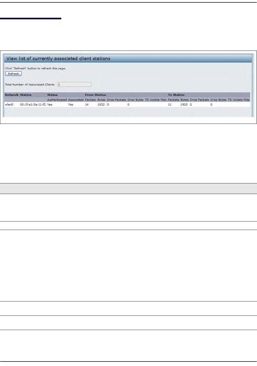
ViewingAssociatedWirelessClientInformation
D-Link UnifiedAccessPointAdministrator’sGuide
November2011 Page38
UnifiedAccessPointAdministrator’sGuide
ViewingAssociatedWirelessClientInformation
Toviewtheclientstationsassociatedwithaparticularaccesspoint,clicktheClientAssociationstab.
Figure7:ViewingClientAssociationInformation
Theassociatedstationsaredisplayedalongwithinformationaboutpackettraffictransmittedandreceivedfor
eachstation.
Table10describesthefieldsontheClientAssociationspage.
Table10:AssociatedClients
Field Description
Network ShowswhichVAPtheclientisassociatedwith.Forexample,anentryofwlan0vap2meansthe
clientisassociatedwithRadio1,VAP2.
Anentryofwlan0meanstheclientisassociatedwithVAP0onRadio1.Anentryofwlan1
meanstheclientisassociatedwithVAP0onRadio2.
Station ShowstheMACaddressoftheassociatedwirelessclient.
Status TheAuthenticatedandAssociatedStatusshowstheunderlyingIEEE802.11authentication
andassociationstatus,whichispresentnomatterwhichtypeofsecuritytheclientusesto
connecttotheAP.ThisstatusdoesnotshowIEEE802.1Xauthenticationorassociationstatus.
Somepointstokeepinmindwithregardtothisfieldare:
•IftheAPsecuritymodeisNoneorStaticWEP,theauthenticationandassociationstatusof
clientsshowingontheClientAssociationspagewillbeinlinewithwhatisexpected;that
is,ifaclientshowsasauthenticatedtotheAP,itwillbeabletotransmitandreceivedata.
(ThisisbecauseStaticWEPusesonlyIEEE802.11authentication.)
•IftheAPusesIEEE802.1XorWPAsecurity,however,itispossibleforaclientassociationto
showonthispageasauthenticated(viatheIEEE802.11security)butactuallynotbe
authenticatedtotheAPviathesecondlayerofsecurity.
FromStation Showsthenumberofpacketsandbytesreceivedfromthewirelessclientandthenumberof
packetsandbytesthatweredroppedafterbeingreceived.
ToStation ShowsthenumberofpacketsandbytestransmittedfromtheAPtothewirelessclientandthe
numberofpacketsandbytesthatweredroppedupontransmission.
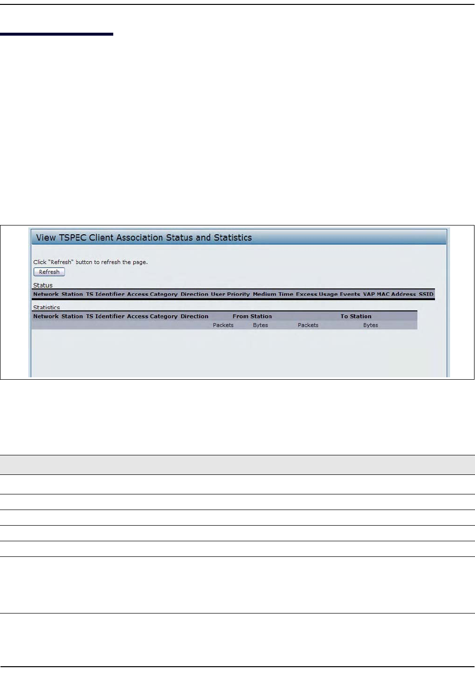
ViewingTSPECClientAssociations
D-Link UnifiedAccessPointAdministrator’sGuide
November2011 Page39
UnifiedAccessPointAdministrator’sGuide
ViewingTSPECClientAssociations
TheTSPECClientAssociationStatusandStatisticspageprovidessomebasicinformationabouttheclient
associationsstatusandareal‐timedisplayofthetransmitandreceivestatisticsfortheTSPECclients.All
transmitandreceivestatisticsshownaretotalssincetheclientassociationstarted.
ATSPECisatrafficspecificationthatissentfromaQoS‐capablewirelessclienttoanAPrequestingacertain
amountofnetworkaccessforthetrafficstream(TS)itrepresents.Atrafficstreamisacollectionofdatapackets
identifiedbythewirelessclientasbelongingtoaparticularuserpriority.Anexampleofavoicetrafficstream
isaWi‐FiCERTIFIED™telephonehandsetthatmarksitscodec‐generateddatapacketsasvoiceprioritytraffic.
Anexampleofavideotrafficstreamisavideoplayerapplicationonawirelesslaptopthatprioritizesavideo
conferencefeedfromacorporateserver.
ToviewTSPECclientassociationstatistics,clicktheTSPECClientAssociationstab.
Figure8:ViewingTSPECClientAssociations
Table11describestheinformationprovidedontheTSPECClientAssociationStatusandStatisticspage.
Table11:TSPECClientAssociations
Field Description
Status
Network Radiointerfaceusedbytheclient.
Station ClientstationMACaddress.
TSIdentifier TSPECTrafficSessionIdentifier(range0‐7).
AccessCategory TSAccessCategory(voiceorvideo).
Direction ThetrafficdirectionforthisTS.Directioncanbe:
• uplink
• downlink
• bidirectional
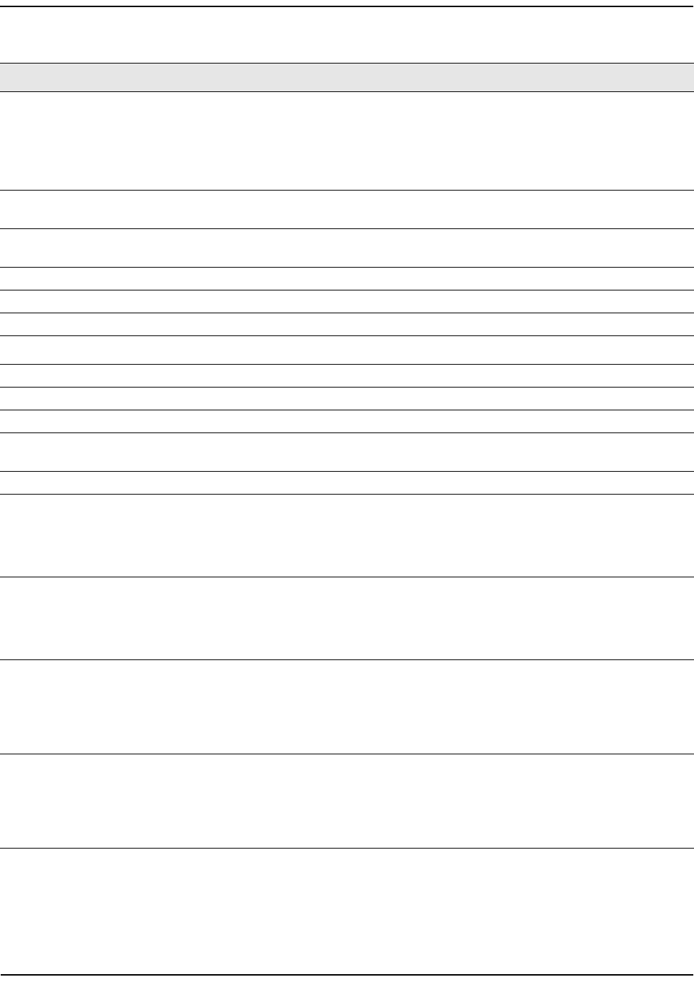
ViewingTSPECClientAssociations
D-Link UnifiedAccessPointAdministrator’sGuide
November2011 Page40
UnifiedAccessPointAdministrator’sGuide
UserPriority TheUserPriority(UP)forthisTS.TheUPissentwitheachpacketintheUPportionof
theIPheader.Typicalvaluesare:
•6or7forvoice
•4or5forvideo
Thevaluemaydifferdependingonotherprioritytrafficsessions.
MediumTime Thetime(in32microsecondpersecondunits)thattheTStrafficoccupiesthe
transmissionmedium.
ExcessUsageEvents ThenumberoftimestheclienthasexceededthemediumtimeestablishedforitsTSPEC.
Minor,infrequentviolationsareignored.
VAP TheVirtualAccessPointassociatedwiththisTSclient.
MACAddress TheVirtualAccessPointMACaddress.
SSID TheservicesetidentifierassociatedwiththisTSclient.
Statistics
Network Radiointerfaceusedbytheclient.
Station ClientstationMACaddress.
TSIdentifier TSPECTrafficSessionIdentifier(range0‐7).
TSType TherewillonlybeanentryintherowforaclientassociationthathasanactiveTS.If
therearenoactivetrafficstreams,thereisnoentryforthestation.
AccessCategory TSAccessCategory(voiceorvideo).
Direction ThetrafficdirectionforthisTS.Directioncanbe:
• uplink
• downlink
• bidirectional
Direction ThetrafficdirectionforthisTS.Directioncanbe:
• uplink
• downlink
• bidirectional
FromStation Showsthenumberofpacketsandbytesreceivedfromthewirelessclientandthe
numberofpacketsandbytesthatweredroppedafterbeingreceived.Alsoshowsthe
numberofpackets:
•inexcessofanadmittedTSPEC.
•forwhichnoTSPEChasbeenestablishedwhenadmissionisrequiredbytheAP.
ToStation ShowsthenumberofpacketsandbytestransmittedfromtheAPtothewirelessclient
andthenumberofpacketsandbytesthatweredroppedupontransmission.Alsoshows
thenumberofpackets:
•inexcessofanadmittedTSPEC.
•forwhichnoTSPEChasbeenestablishedwhenadmissionisrequiredbytheAP.
Table11:TSPECClientAssociations(Cont.)
Field Description
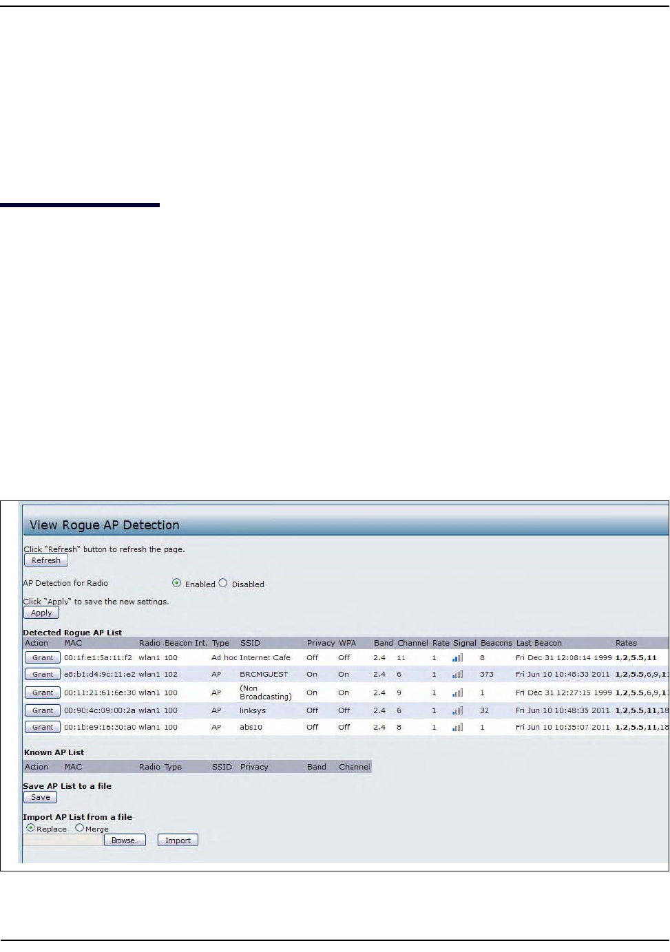
ViewingRogueAPDetection
D-Link UnifiedAccessPointAdministrator’sGuide
November2011 Page41
UnifiedAccessPointAdministrator’sGuide
LinkIntegrityMonitoring
TheUAPprovideslinkintegritymonitoringtocontinuallyverifyitsconnectiontoeachassociatedclient.Todo
this,theAPsendsdatapacketstoclientseveryfewsecondswhennoothertrafficispassing.ThisallowstheAP
todetectwhenaclientgoesoutofrange,evenduringperiodswhennonormaltrafficisexchanged.Theclient
connectiondropsoffthelistwithin300secondsifthesedatapacketsarenotacknowledged,evenifno
disassociationmessageisreceived.
ViewingRogueAPDetection
ThestatuspagetoviewRogueAPDetectioninformationprovidesreal‐timestatisticsforallAPswithinrange
oftheAPonwhichyouareviewingtheAdministrationWebpages.WhenAPdetectionisenabled,theradio
willperiodicallyswitchfromitsoperatingchanneltoscanotherchannelswithinthesameband.ClickRefresh
toupdatethescreenanddisplaythemostcurrentinformation.
TheRogueAPDetectionpagecontainsthefollowingtwolists:
• DetectedRogueAPList—ListsallAPswithinrangeoftheAPthathavenotbeenacknowledgedasknown
APs.
•KnownAPList—ListsallAPswithinrangeoftheAPthathavebeenacknowledgedasknownAPseitherby
clickingtheGrantbuttonassociatedwithanAPintheDetectedRogueAPListorbyappearinginan
importedAPlist.
Toviewinformationaboutotheraccesspointsonthewirelessnetwork,clicktheRogueAPDetectiontab.
Figure9:ViewingRogueandKnownAccessPoints
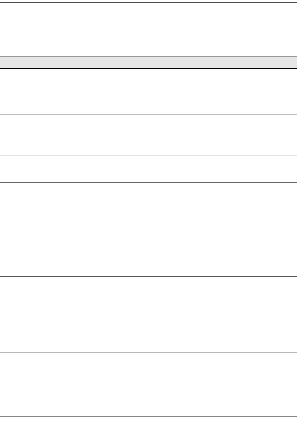
ViewingRogueAPDetection
D-Link UnifiedAccessPointAdministrator’sGuide
November2011 Page42
UnifiedAccessPointAdministrator’sGuide
YoumustenabletheAPdetectiononaradioinordertocollectinformationaboutotherAPswithinrange.
Table12describestheinformationprovidedonneighboringaccesspoints.
Table12:RogueAPDetection
Field Description
APDetectionfor
Radio
ToallowtheAPradiostoperformneighborAPdetectionandcollectinformationabout
neighborAPs,clickEnabled.
TodisableneighborAPdetectionontheradios,clickDisabled.
IfyouchangetheAPdetectionmode,clickApplytosavethenewsettings.
DetectedRogueAPList
Action ClickGranttomovetheAPfromtheDetectedRogueAPListtotheKnownAPList.
Note:TheDetectedRougeAPandKnownAPlistsprovideinformation.TheDWL‐x600AP
doesnothaveanycontrolovertheAPsonthelistandcannotapplyanysecuritypolicies
toAPsdetectedthroughtheRFscan.
MAC ShowstheMACaddressoftheneighboringAP.
Radio TheRadiofieldindicateswhichradiodetectedtheneighboringAP:
•wlan0(RadioOne)
•wlan1(RadioTwo)
BeaconInt. ShowstheBeaconintervalbeingusedbythisAP.
BeaconframesaretransmittedbyanAPatregularintervalstoannouncetheexistenceof
thewirelessnetwork.Thedefaultbehavioristosendabeaconframeonceevery100
milliseconds(or10persecond).
TheBeaconIntervalissetontheRadiopage.(See“ModifyingRadioSettings”onpage58.)
Type Indicatesthetypeofdevice:
•APindicatestheneighboringdeviceisanAPthatsupportstheIEEE802.11Wireless
NetworkingFrameworkinInfrastructureMode.
•AdhocindicatesaneighboringstationrunninginAdhocMode.Stationssettoadhoc
modecommunicatewitheachotherdirectly,withouttheuseofatraditionalAP.Ad‐
hocmodeisanIEEE802.11WirelessNetworkingFrameworkalsoreferredtoaspeer‐
to‐peermodeoranIndependentBasicServiceSet(IBSS).
SSID TheServiceSetIdentifier(SSID)fortheAP.
TheSSIDisanalphanumericstringofupto32charactersthatuniquelyidentifiesawireless
localareanetwork.ItisalsoreferredtoastheNetworkName.
TheSSIDissetontheVAPpage.(See“ConfiguringLoadBalancing”onpage88.)
Privacy Indicateswhetherthereisanysecurityontheneighboringdevice.
•OffindicatesthattheSecuritymodeontheneighboringdeviceissettoNone(no
security).
•Onindicatesthattheneighboringdevicehassomesecurityinplace.
SecurityisconfiguredontheAPfromtheVAPpage.
WPA IndicateswhetherWPAsecurityisonoroffforthisAP.

ViewingRogueAPDetection
D-Link UnifiedAccessPointAdministrator’sGuide
November2011 Page43
UnifiedAccessPointAdministrator’sGuide
Band ThisindicatestheIEEE802.11modebeingusedonthisAP.(Forexample,IEEE802.11a,
IEEE802.11b,IEEE802.11g.)
Thenumbershownindicatesthemodeaccordingtothefollowingmap:
•2.4indicatesIEEE802.11b,802.11g,or802.11nmode(oracombinationofthemodes)
•5indicatesIEEE802.11aor802.11nmode(orbothmodes)
Channel ShowstheChannelonwhichtheAPiscurrentlybroadcasting.
Thechanneldefinestheportionoftheradiospectrumthattheradiousesfortransmitting
andreceiving.
ThechannelissetinRadioSettings.(See“ModifyingRadioSettings”onpage58.)
Rate Showstherate(inmegabitspersecond)atwhichthisAPiscurrentlytransmitting.
ThecurrentratewillalwaysbeoneoftheratesshowninSupportedRates.
Signal IndicatesthestrengthoftheradiosignalemittingfromthisAP.Ifyouhoverthemouse
pointeroverthebars,anumberappearsandshowsthestrengthindecibels(dB).
Beacons ShowsthetotalnumberofbeaconsreceivedfromthisAPsinceitwasfirstdiscovered.
LastBeacon ShowsthedateandtimeofthelastbeaconreceivedfromthisAP.
Rates Showssupportedandbasic(advertised)ratesetsfortheneighboringAP.Ratesareshown
inmegabitspersecond(Mbps).
AllSupportedRatesarelisted,withBasicRatesshowninbold.
RatesetsareconfiguredontheRadioSettingspage.(See“ModifyingRadioSettings”on
page58.)
KnownAPList
Action AnAPcanappearintheKnownAPListifithasbeenmovedfromtheDetectedRogueAP
ListbyclickingtheGrantbuttonoriftheMACaddressoftheAPappearsinanAPlistthat
hasbeenimported.
TomovetheAPfromtheKnownAPListtotheDetectedRogueAPList,clickDelete.
Note:TheDetectedRougeAPandKnownAPlistsprovideinformation.TheDWL‐x600AP
doesnothaveanycontrolovertheAPsonthelistandcannotapplyanysecuritypolicies
toAPsdetectedthroughtheRFscan.
MAC ShowstheMACaddressoftheneighboringAP.
Radio TheRadiofieldindicateswhichradiodetectedtheneighboringAP:
•wlan0(RadioOne)
•wlan1(RadioTwo)
Type Indicatesthetypeofdevice:
•APindicatestheneighboringdeviceisanAPthatsupportstheIEEE802.11Wireless
NetworkingFrameworkinInfrastructureMode.
•AdhocindicatesaneighboringstationrunninginAdhocMode.Stationssettoadhoc
modecommunicatewitheachotherdirectly,withouttheuseofatraditionalAP
.Ad‐
hocmodeisanIEEE802.11WirelessNetworkingFrameworkalsoreferredtoaspeer‐
to‐peermodeoranIndependentBasicServiceSet(IBSS).
SSID TheServiceSetIdentifier(SSID)fortheAP.
TheSSIDisanalphanumericstringofupto32charactersthatuniquelyidentifiesawireless
localareanetwork.ItisalsoreferredtoastheNetworkName.
TheSSIDissetontheVAPpage.(See“ConfiguringLoadBalancing”onpage88.)
Table12:RogueAPDetection(Cont.)
Field Description

ViewingRogueAPDetection
D-Link UnifiedAccessPointAdministrator’sGuide
November2011 Page44
UnifiedAccessPointAdministrator’sGuide
SavingandImportingtheKnownAPList
TosavetheKnownAPlisttoafile,clickSave.ThelistcontainstheMACaddressesofallAPthathavebeen
addedtotheKnownAPList.Bydefault,thefilenameisRogue1.cfg.YoucanuseatexteditororWebbrowser
toopenthefileandviewitscontents.
UsetheImportfeaturetoimportalistofKnownAPsfromasavedlist.ThelistmightbefromanotherDWL‐
x600APorcreatedfromatextfile.IftheMACaddressofanAPappearsintheKnownAPList,itwillnotbe
detectedasarogue.
ToimportanAPListfromafile,usethefollowingsteps:
1. ChoosewhethertoreplacetheexistingKnownAPlistoraddtheentriesintheimportedfiletotheKnown
APlist.
• SelecttheReplaceoptiontoimportthelistandreplacethecontentsoftheKnownAPList.
•SelecttheMergeoptiontoimportthelistandaddtheAPsintheimportedfiletotheAPscurrently
displayedintheKnownAPList.
2. ClickBrowseandchoosethefiletoimport.
Thefileyouimportmustbeaplain‐textfilewitha.txtor.cfgextension.EntriesinthefileareMAC
addressesinhexidecimalformatwitheachoctetseparatedbycolons,forexample00:11:22:33:44:55.
Separateentrieswithasinglespace.FortheAPtoacceptthefile,itmustcontainonlyMACaddresses.
3. ClickImport.
Oncetheimportiscomplete,thescreenrefreshesandtheMACaddressesoftheAPsintheimportedfile
appearintheKnownAPList.
Privacy Indicateswhetherthereisanysecurityontheneighboringdevice.
•OffindicatesthattheSecuritymodeontheneighboringdeviceissettoNone(no
security).
•Onindicatesthattheneighboringdevicehassomesecurityinplace.
SecurityisconfiguredontheAPfromtheVAPpage.
Band ThisindicatestheIEEE802.11modebeingusedonthisAP.(Forexample,IEEE802.11a,
IEEE802.11b,IEEE802.11g.)
Thenumbershownindicatesthemodeaccordingtothefollowingmap:
•2.4indicatesIEEE802.11b,802.11g,or802.11nmode(oracombinationofthemodes)
•5indicatesIEEE802.11aor802.11nmode(orbothmodes)
Channel ShowstheChannelonwhichtheAPiscurrentlybroadcasting.
Thechanneldefinestheportionoftheradiospectrumthattheradiousesfortransmitting
andreceiving.
ThechannelissetinRadioSettings.(See“ModifyingRadioSettings”onpage58.)
Table12:RogueAPDetection(Cont.)
Field Description
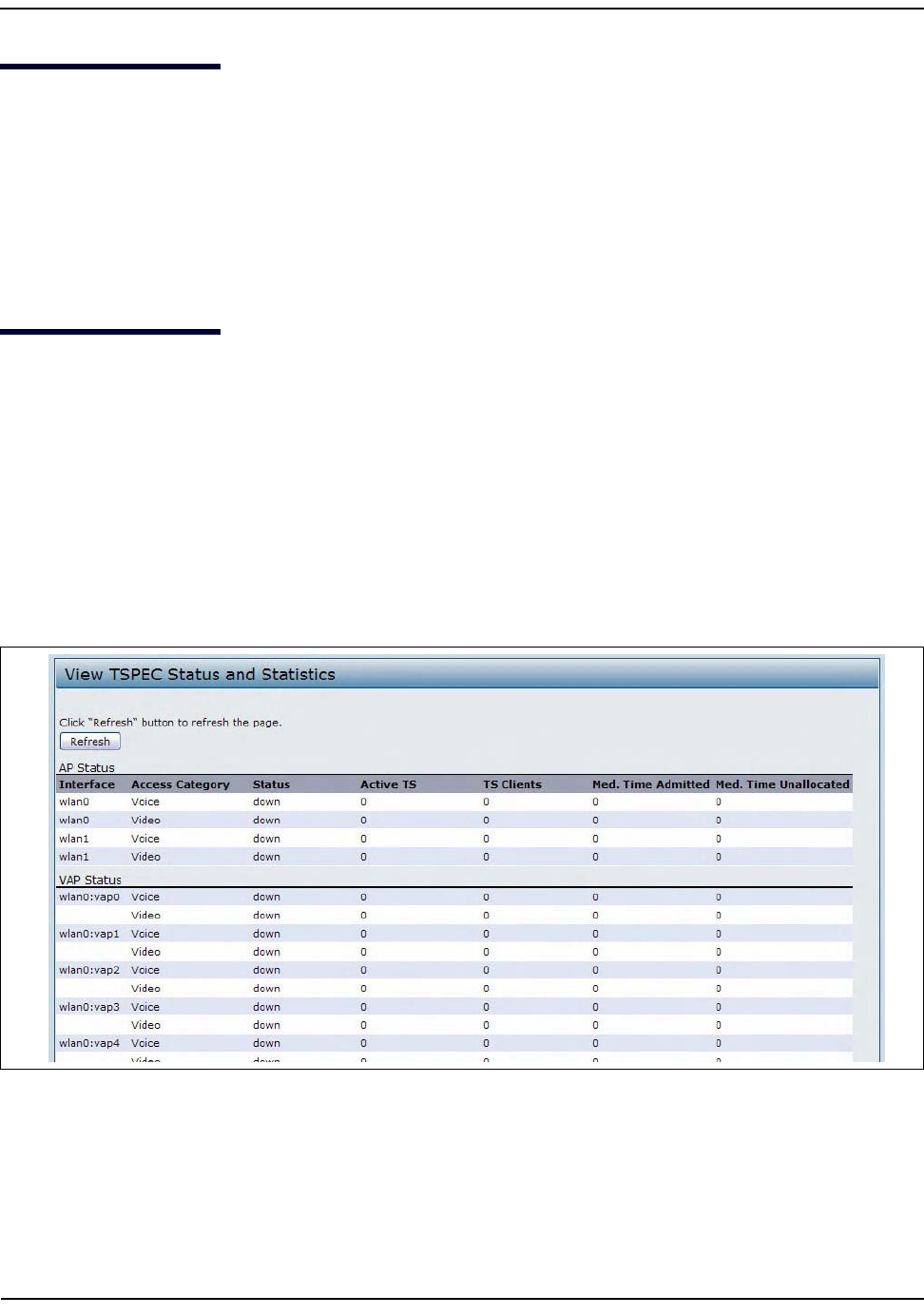
ViewingManagedAPDHCPInformation
D-Link UnifiedAccessPointAdministrator’sGuide
November2011 Page45
UnifiedAccessPointAdministrator’sGuide
ViewingManagedAPDHCPInformation
TheUAPcanlearnaboutD‐LinkUnifiedWirelessSwitchesonthenetworkthroughDHCPresponsestoitsinitial
DHCPrequest.TheManagedAPDHCPpagedisplaystheDNSnamesorIPaddressesofuptofourD‐LinkUnified
WirelessSwitchesthattheAPlearnedaboutfromaDHCPserveronyournetwork.
ForinformationabouthowtoconfigureaDHCPservertorespondtoAPDHCPrequestswiththeswitchIP
addressinformation,seetheUserManualfortheswitch.
ViewingTSPECStatusandStatisticsInformation
TheTSPECStatusandStatisticspageprovides:
•SummaryinformationaboutTSPECsessionsbyradio
•SummaryinformationaboutTSPECsessionsbyVAP
•Real‐timetransmitandreceivestatisticsfortheTSPECVAPsonallradiointerfaces.
AllofthetransmitandreceivestatisticsshownaretotalssincetheAPwaslaststarted.IfyoureboottheAP,
thesefiguresindicatetransmitandreceivetotalssincethereboot.
ToviewTSPECstatusandstatistics,clicktheTSPECStatusandStatisticstab.
Figure10:ViewingTSPECStatusandStatistics
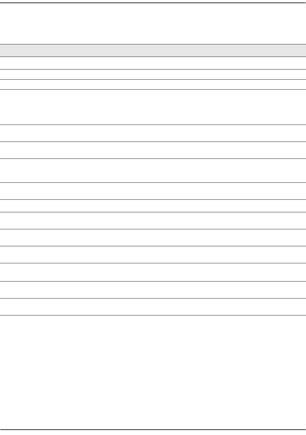
ViewingTSPECStatusandStatisticsInformation
D-Link UnifiedAccessPointAdministrator’sGuide
November2011 Page46
UnifiedAccessPointAdministrator’sGuide
Table13describestheinformationprovidedonTSPECStatusandStatisticspage.
Table13:TSPECStatusandStatistics
Field Description
APandVAPStatus
Interface IndicatesthenameoftheRadioorVAPinterface.
AccessCategory IndicatesCurrentAccessCategoryassociatedwiththisTrafficStream(voiceorvideo).
Status IndicateswhethertheTSPECsessionisenabled(up)ornot(down)forthecorresponding
AccessCategory.
Note:Thisisaconfigurationstatus(doesnotnecessarilyrepresentthecurrentsession
activity).
ActiveTS IndicatesthenumberofcurrentlyactiveTSPECTrafficStreamsforthisradioandAccess
Category.
TSClients IndicatesthenumberofTrafficStreamclientsassociatedwiththisradioandAccess
Category.
MediumTime
Admitted
Time(in32microsecondpersecondunits)allocatedforthisAccessCategoryoverthe
transmissionmediumtocarrydata.Thisvalueshouldbelessthanorequaltothe
maximumbandwidthallowedoverthemediumforthisTS.
MediumTime
Unallocated
Time(in32microsecondpersecondunits)ofunusedbandwidthforthisAccess
Category.
TransmitandReceiveStatistics
TotalPackets IndicatesthetotalnumberofTSpacketssent(inTransmittable)orreceived(inReceived
table)bythisRadioforthespecifiedAccessCategory.
TotalBytes IndicatesthetotalnumberofTSbytessent(inTransmittable)orreceived(inReceived
table)bythisRadioforthespecifiedAccessCategory.
TotalVoicePackets IndicatesthetotalnumberofTSvoicepacketssent(inTransmittable)orreceived(in
Receivedtable)bythisAPforthisVAP.
TotalVoiceBytes IndicatesthetotalTSvoicebytessent(inTransmittable)orreceived(inReceivedtable)
bythisAPforthisVAP.
TotalVideoPackets IndicatesthetotalnumberofTSvideopacketssent(inTransmittable)orreceived(in
Receivedtable)bythisAPforthisVAP.
TotalVideoBytes IndicatesthetotalTSvideobytessent(inTransmittable)orreceived(inReceivedtable)
bythisAPforthisVAP.
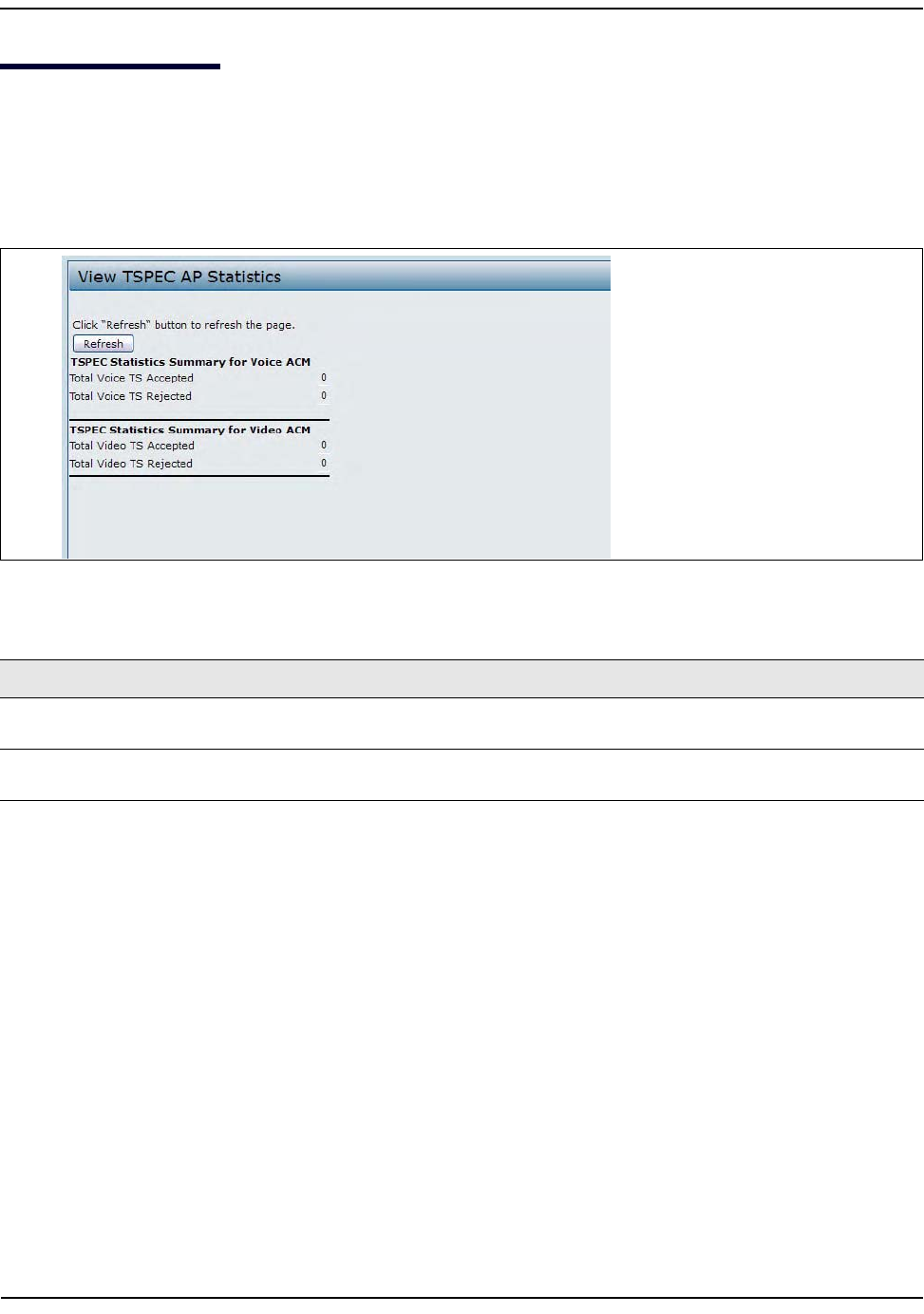
ViewingTSPECAPStatisticsInformation
D-Link UnifiedAccessPointAdministrator’sGuide
November2011 Page47
UnifiedAccessPointAdministrator’sGuide
ViewingTSPECAPStatisticsInformation
TheViewTSPECAPStatisticspageprovidesinformationonthevoiceandvideoTrafficStreamsacceptedand
rejectedbytheAP.
ToviewTSPECAPstatistics,clicktheTSPECAPStatisticstab.
Table14describestheinformationprovidedonTSPECAPStatisticspage.
Table14:TSPECAPStatistics
Field Description
TSPECStatisticsSummaryfor
VoiceACM
Indicatesthetotalnumberofacceptedandthetotalnumberofrejected
voiceTrafficStreams.
TSPECStatisticsSummaryfor
VideoACM
Indicatesthetotalnumberofacceptedandthetotalnumberofrejected
videoTrafficStreams.
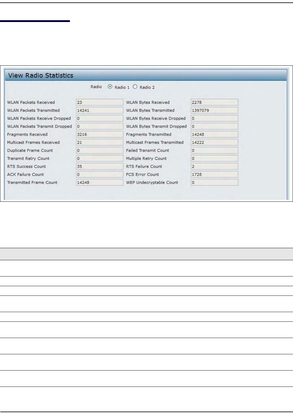
ViewingRadioStatisticsInformation
D-Link UnifiedAccessPointAdministrator’sGuide
November2011 Page48
UnifiedAccessPointAdministrator’sGuide
ViewingRadioStatisticsInformation
TheRadioStatisticspageprovidesdetailedinformationaboutthepacketsandbytestransmittedandreceived
ontheradiointerfaceofthisaccesspoint.
Figure11:RadioStatistics
ThefollowingtabledescribesdetailsabouttheRadioStatisticsinformation.
Table15:RadioStatisticsInformation
Field Description
Radio Chooseeitherradio1orradio2toviewstatisticsfortheselectedradio
(DWL‐8600APandDWL‐6600APonly).
WLANPacketsReceived TotalpacketsreceivedbytheAPonthisradiointerface.
WLANBytesReceived TotalbytesreceivedbytheAPonthisradiointerface.
WLANPackets
Transmitted
TotalpacketstransmittedbytheAPonthisradiointerface.
WLANBytesTransmitted TotalbytestransmittedbytheAPonthisradiointerface.
WLANPacketsReceive
Dropped
NumberofpacketsreceivedbytheAPonthisradiointerfacethatweredropped.
WLANBytesReceive
Dropped
NumberofbytesreceivedbytheAPonthisradiointerfacethatweredropped.
WLANPacketsTransmit
Dropped
NumberofpacketstransmittedbytheAPonthisradiointerfacethatwere
dropped.
WLANBytesTransmit
Dropped
NumberofbytestransmittedbytheAPonthisradiointerfacethatweredropped.
ViewingRadioStatisticsInformation
D-Link UnifiedAccessPointAdministrator’sGuide
November2011 Page49
UnifiedAccessPointAdministrator’sGuide
FragmentsReceived CountofsuccessfullyreceivedMPDUframesoftypedataormanagement.
FragmentsTransmitted NumberoftransmittedMPDUwithanindividualaddressoranMPDUwitha
multicastaddressoftypeDataorManagement.
MulticastFrames
Received
CountofMSDUframesreceivedwiththemulticastbitsetinthedestinationMAC
address.
MulticastFrames
Transmitted
CountofsuccessfullytransmittedMSDUframeswherethemulticastbitissetinthe
destinationMACaddress.
DuplicateFrameCount NumberoftimesaframeisreceivedandtheSequenceControlfieldindicatesisa
duplicate.
FailedTransmitCount NumberoftimesanMSDUisnottransmittedsuccessfullyduetotransmitattempts
exceedingeithertheshortretrylimitorthelongretrylimit.
TransmitRetryCount NumberoftimesanMSDUissuccessfullytransmittedafteroneormoreretries.
MultipleRetryCount NumberoftimesanMSDUissuccessfullytransmittedaftermorethanoneretry.
RTSSuccessCount CountofCTSframesreceivedinresponsetoanRTSframe.
RTSFailureCount CountofCTSframesnotreceivedinresponsetoanRTSframe.
ACKFailureCount CountofACKframesnotreceivedwhenexpected.
FCSErrorCount CountofFCSerrorsdetectedinareceivedMPDUframe.
FramesTransmitted CountofeachsuccessfullytransmittedMSDU.
WEPUndecryptable
Count
Countofencryptedframesreceivedandthekeyconfigurationofthetransmitter
indicatesthattheframeshouldnothavebeenencryptedorthatframewas
discardedduetothereceivingstationnotimplementingtheprivacyoption.
Table15:RadioStatisticsInformation(Cont.)
Field Description
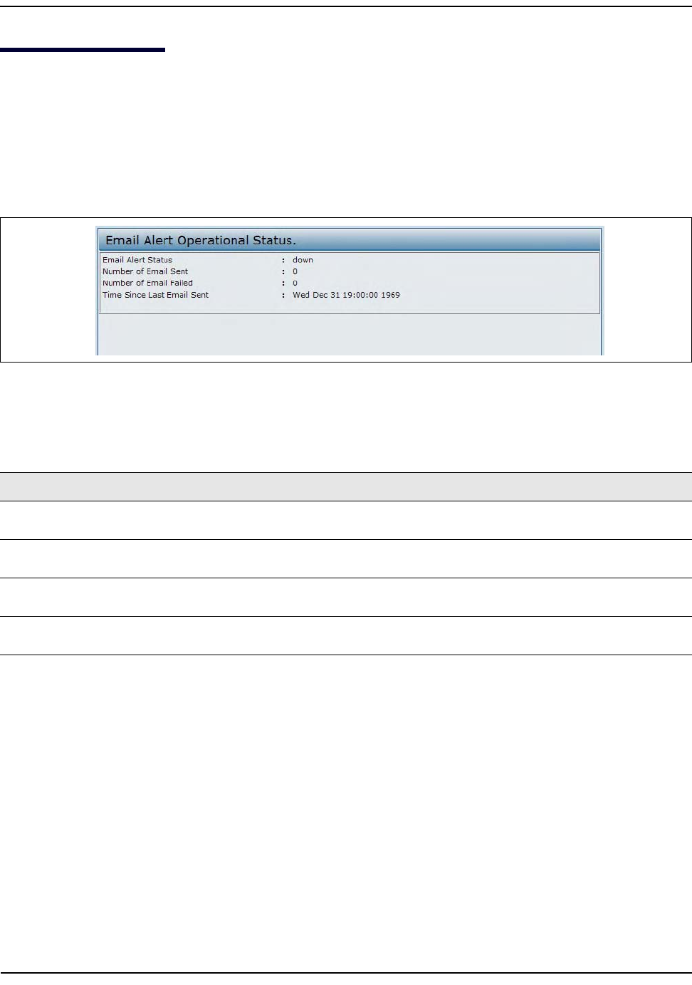
ViewingEmailAlertOperationalStatus
D-Link UnifiedAccessPointAdministrator’sGuide
November2011 Page50
UnifiedAccessPointAdministrator’sGuide
ViewingEmailAlertOperationalStatus
TheEmailAlertOperationalStatuspageprovidesinformationabouttheemailalertssentbasedonthesyslog
messagesgeneratedintheAP.
ToviewtheEmailAlertOperationalStatus,clicktheStatus>EmailAlertStatustab.
Toconfiguretheemailalerts,see“ConfiguringEmailAlert”onpage106
Figure12:EmailAlertOperationalStatus
ThefollowingtabledescribesdetailsabouttheEmailAlertOperationalStatus.
Table16:EmailAlertStatus
Field Description
EmailAlertStatus TheEmailAlertoperationalstatusThestatusiseitherUporDown.Thedefaultis
Down.
NumberofEmailSent Thetotalnumberofemailsentsofar.Therangeisanunsignedintegerof32bits.
Thedefaultis0.
NumberofEmailFailed Thetotalnumberofemailfailuressofar.Therangeisanunsignedintegerof32
bits.Thedefaultis0.
TimeSinceLastEmail
Sent
Thetimesincethelastemailwassent.Timeformatisused.Thedefaultis00days
00hours00mins00secs.

ManagingtheAccessPoint
D-Link UnifiedAccessPointAdministrator’sGuide
November2011 Page51
UnifiedAccessPointAdministrator’sGuide
Section4:ManagingtheAccessPoint
ThissectiondescribeshowtomanagetheUAPandcontainsthefollowingsubsections:
•“EthernetSettings”
•“WirelessSettings”
•“ModifyingRadioSettings”
•“ConfiguringRadioandVAPScheduler”
•“SchedulerAssociationSettings”
•“VirtualAccessPointSettings”
•“ConfiguringtheWirelessDistributionSystem(WDS)”
•“ControllingAccessbyMACAuthentication”
•“ConfiguringLoadBalancing”
•“ManagedAccessPointOverview”
•“Configuring802.1XAuthentication”
•“CreatingaManagementAccessControlList”
TheconfigurationpagesforthefeaturesinthissectionarelocatedundertheManageheadingonthe
AdministrationWebUI.
EthernetSettings
Thedefaultwiredinterfacesettings,whichincludeDHCPandVLANinformation,mightnotworkforall
networks.
Bydefault,theDHCPclientontheUAPautomaticallybroadcastsrequestsfornetworkinformation.Ifyouwant
touseastaticIPaddress,youmustdisabletheDHCPclientandmanuallyconfiguretheIPaddressandother
networkinformation.
ThemanagementVLANisVLAN1bydefault.ThisVLANisalsothedefaultuntaggedVLAN.Ifyoualreadyhave
amanagementVLANconfiguredonyournetworkwithadifferentVLANID,youmustchangetheVLANIDof
themanagementVLANontheAP.
ToconfiguretheLANsettings,clicktheEthernetSettingstab.
Note:Theweb‐basedUIimagesinthissectionshowtheDWL‐8600APadministrationpages.Pages
fortheDWL‐3600APdisplayinformationforoneradioonly.
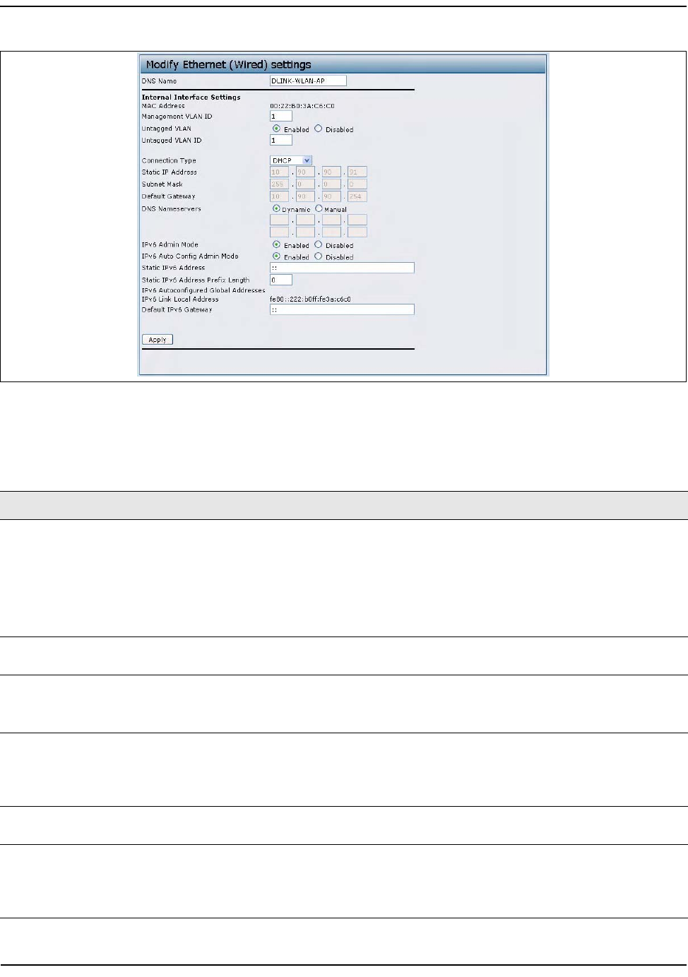
EthernetSettings
D-Link UnifiedAccessPointAdministrator’sGuide
November2011 Page52
UnifiedAccessPointAdministrator’sGuide
Figure13:EthernetSettings
ThefollowingtabledescribesthefieldstovieworconfigureontheEthernetSettingspage.
Table17:EthernetSettingsPage
FieldDescription
Hostname EnterahostnamefortheAP.ThehostnameappearsintheCLIprompt.
Thehostnamehasthefollowingrequirements:
•Thelengthmustbebetween1–63characters.
• Upperandlowercasecharacters,numbers,andhyphensareaccepted.
•Thefirstcharactermustbealetter(a–zorA–Z),andthelastcharactercannotbea
hyphen.
MACAddress ShowstheMACaddressfortheLANinterfacefortheEthernetportonthisAP.Thisisa
read‐onlyfieldthatyoucannotchange.
ManagementVLAN
ID
ThemanagementVLANistheVLANassociatedwiththeIPaddressyouusetoaccessthe
AP.ThedefaultmanagementVLANIDis1.
Provideanumberbetween1and4094forthemanagementVLANID.
UntaggedVLAN IfyoudisabletheuntaggedVLAN,alltrafficistaggedwithaVLANID.
BydefaultalltrafficontheUAPusesVLAN1,whichisthedefaultuntaggedVLAN.This
meansthatalltrafficisuntaggeduntilyoudisabletheuntaggedVLAN,changethe
untaggedtrafficVLANID,orchangetheVLANIDforaVAPorclientusingRADIUS.
UntaggedVLANID Provideanumberbetween1and4094fortheuntaggedVLANID.TrafficontheVLAN
thatyouspecifyinthisfieldwillnotbetaggedwithaVLANID.
ConnectionType IfyouselectDHCP,theUAPacquiresitsIPaddress,subnetmask,DNS,andgateway
informationfromaDHCPserver.
IfyouselectStaticIP,youmustenterinformationintheStaticIPAddress,SubnetMask,
andDefaultGatewayfields.
EthernetSettings
D-Link UnifiedAccessPointAdministrator’sGuide
November2011 Page53
UnifiedAccessPointAdministrator’sGuide
StaticIPAddress EnterthestaticIPaddressinthetextboxes.ThisfieldisdisabledifyouuseDHCPasthe
connectiontype.
SubnetMask EntertheSubnetMaskinthetextboxes.
DefaultGateway EntertheDefaultGatewayinthetextboxes.
DNSNameservers SelectthemodefortheDNS.
InDynamicmode,theIPaddressesfortheDNSserversareassignedautomaticallyvia
DHCP.ThisoptionisonlyavailableifyouspecifiedDHCPfortheConnectionType.
InManualmode,youmustassignstaticIPaddressestoresolvedomainnames.
IPv6AdminMode EnableordisableIPv6managementaccesstotheAP
IPv6AutoConfig
AdminMode
EnableordisableIPv6autoaddressconfigurationontheAP.
WhenIPv6AutoConfigModeisenabled,automaticIPv6addressconfigurationand
gatewayconfigurationisallowedbyprocessingtheRouterAdvertisementsreceivedon
theLANport.TheAPcanhavemultipleautoconfiguredIPv6addresses.
StaticIPv6Address EnterastaticIPv6address.TheAPcanhaveastaticIPv6addressevenifaddresseshave
alreadybeenconfiguredautomatically.
StaticIPv6Address
PrefixLength
EnterthestaticIPv6prefixlength,whichisanintegerintherangeof0–128.
IPv6
Autoconfigured
GlobalAddresses
IftheAPhasbeenassignedoneormoreIPv6addressesautomatically,theaddressesare
listed.
IPv6LinkLocal
Address
ShowstheIPv6LinkLocaladdress,whichistheIPv6addressusedbythelocalphysical
link.ThelinklocaladdressisnotconfigurableandisassignedbyusingtheIPv6Neighbor
Discoveryprocess.
DefaultIPv6
Gateway
EnterthedefaultIPv6gateway.
Note:Afteryouconfigurethewiredsettings,youmustclickApplytoapplythechangesandtosave
thesettings.ChangingsomesettingsmightcausetheAPtostopandrestartsystemprocesses.Ifthis
happens,wirelessclientswilltemporarilyloseconnectivity.WerecommendthatyouchangeAP
settingswhenWLANtrafficislow.
Table17:EthernetSettingsPage(Cont.)
FieldDescription
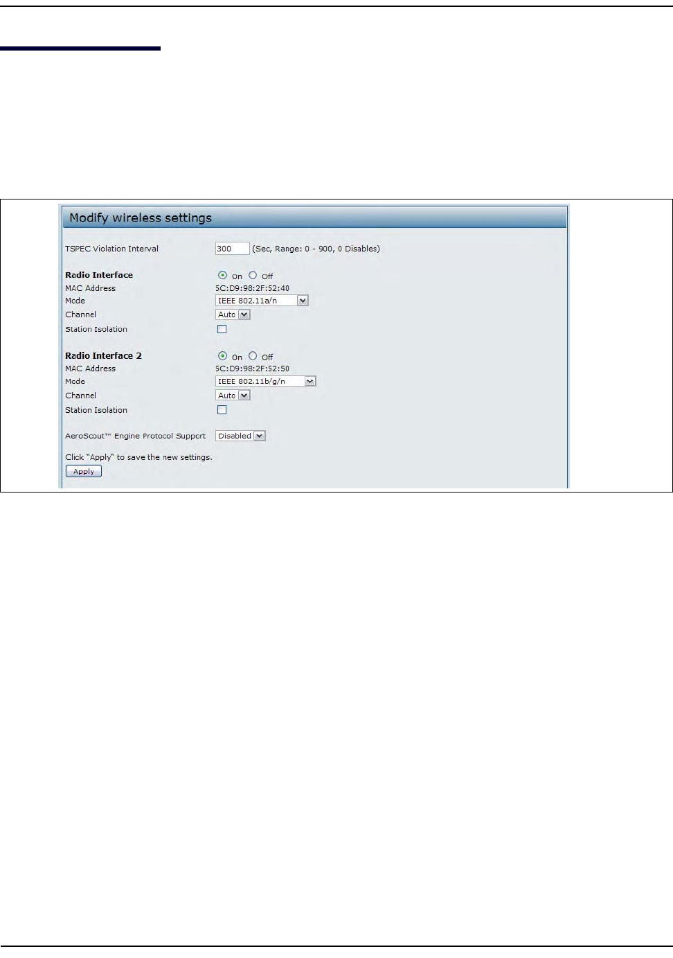
WirelessSettings
D-Link UnifiedAccessPointAdministrator’sGuide
November2011 Page54
UnifiedAccessPointAdministrator’sGuide
WirelessSettings
Wirelesssettingsdescribeaspectsofthelocalareanetwork(LAN)relatedspecificallytotheradiodeviceinthe
accesspoint(802.11ModeandChannel)andtothenetworkinterfacetotheaccesspoint(MACaddressfor
accesspointandWirelessNetworkname,alsoknownasSSID).
Toconfigurethewirelessinterface,clicktheManage>WirelessSettingstab.
Figure14:WirelessInterfaceConfiguration

WirelessSettings
D-Link UnifiedAccessPointAdministrator’sGuide
November2011 Page55
UnifiedAccessPointAdministrator’sGuide
Table18describesthefieldsandconfigurationoptionsavailableontheWirelessSettingspage.
Table18:WirelessSettings
Field Description
TSPECViolation
Interval
Specifythetimeinterval(inseconds)fortheAPtoreport(throughthesystemlogand
SNMPtraps)associatedclientsthatdonotadheretomandatoryadmissioncontrol
procedures.
RadioInterface Specifywhetheryouwanttheradiointerfaceonoroff.
MACAddress IndicatestheMediaAccessControl(MAC)addressesfortheinterface.Dual‐radioAPshave
auniqueMACaddressforeachradio.
AMACaddressisapermanent,uniquehardwareaddressforanydevicethatrepresents
aninterfacetothenetwork.TheMACaddressisassignedbythemanufacturer.Youcannot
changetheMACaddress.Itisprovidedhereforinformationalpurposesasaunique
identifierforaninterface.
Mode TheModedefinesthePhysicalLayer(PHY)standardtheradiouses.
Selectoneofthefollowingmodesforradio1(DWL‐6600APandDWL‐8600APonly):
•IEEE802.11aisaPHYstandardthatspecifiesoperatinginthe5GHzU‐NIIbandusing
orthogonalfrequencydivisionmultiplexing(OFDM).Itsupportsdataratesranging
from6to54Mbps.
•IEEE802.11a/noperatesinthe5GHzISMbandandincludessupportforboth802.11a
and802.11ndevices.IEEE802.11nisanextensionofthe802.11standardthatincludes
multiple‐inputmultiple‐output(MIMO)technology.IEEE802.11nsupportsdataranges
ofupto248Mbpsandnearlytwicetheindoorrangeof802.11b,802.11g,and
802.11a.
•5GHzIEEE802.11nistherecommendedmodefornetworkswith802.11ndevicesthat
operateinthe5GHzfrequencythatdonotneedtosupport802.11adevices.IEEE
802.11ncanachieveahigherthroughputwhenitdoesnotneedtobecompatiblewith
legacydevices(802.11a).
Selectoneofthefollowingmodesforradio2:
•IEEE802.11b/goperatesinthe2.4GHzISMband.IEEE802.11bisanenhancementof
theinitial802.11PHYtoinclude5.5Mbpsand11Mbpsdatarates.Itusesdirect
sequencespreadspectrum(DSSS)orfrequencyhoppingspreadspectrum(FHSS)as
wellascomplementarycodekeying(CCK)toprovidethehigherdatarates.Itsupports
dataratesrangingfrom1to11Mbps.IEEE802.11gisahigherspeedextension(upto
54Mbps)tothe802.11bPHY.Itusesorthogonalfrequencydivisionmultiplexing
(OFDM).Itsupportsdataratesrangingfrom1to54Mbps.
•IEEE802.11b/g/noperatesinthe2.4GHzISMbandandincludessupportfor802.11b,
802.11g,and802.11ndevices.
•2.4GHzIEEE802.11nistherecommendedmodefornetworkswith802.11ndevices
thatoperateinthe2.4GHzfrequencythatdonotneedtosupport802.11b/gdevices.
IEEE802.11ncanachieveahigherthroughputwhenitdoesnotneedtobecompatible
withlegacydevices(802.11b/g).

WirelessSettings
D-Link UnifiedAccessPointAdministrator’sGuide
November2011 Page56
UnifiedAccessPointAdministrator’sGuide
Channel SelecttheChannel.
Therangeofavailablechannelsisdeterminedbythemodeoftheradiointerface
.If youselect Auto forthechannel setting,theAP scansavailablechannels.and.selects
a channel wherenotraffic isdetected.
TheChanneldefinestheportionoftheradiospectrumtheradiousesfortransmittingand
receiving.Eachmodeoffersanumberofchannels,dependingonhowthespectrumis
licensedbynationalandtransnationalauthoritiessuchastheFederalCommunications
Commission(FCC)ortheInternationalTelecommunicationUnion(ITU‐R).
WhenautomaticchannelassignmentisenabledontheChannelManagementpagefor
Clustering,thechannelpolicyfortheradioisautomaticallysettostaticmode,andthe
AutooptionisnotavailablefortheChannelfield.Thisallowstheautomaticchannel
featuretosetthechannelsfortheradiosinthecluster.
StationIsolation ToenableStationIsolation,selectthecheckboxdirectlybesideit.
WhenStationIsolationisdisabled,wirelessclientscancommunicatewithoneanother
normallybysendingtrafficthroughtheAP.
WhenStationIsolationisenabled,theAPblockscommunicationbetweenwirelessclients
onthesameradioandVAP.TheAPstillallowsdatatrafficbetweenitswirelessclientsand
wireddevicesonthenetwork,acrossaWDSlink,andwithotherwirelessclients
associatedwithadifferentVAP,butnotamongwirelessclientsassociatedwiththesame
VAP.
Note:Ondual‐radioAPs,StationIsolationdoesnotblockcommunicationbetweenRadio1
andRadio2,eveniftheVAPconfigurationoneachradioisthesame.
AeroScout™
EngineProtocol
Support
AeroScoutEnginesupportprovideslocation‐basedservicesforwirelessnetworks.Specify
whethertoenablesupportfortheAeroScoutprotocol.
OptionsareEnabledorDisabled.ThedefaultisDisabled.Whenenabled,Aeroscout
devicesarerecognizedanddataissenttoanAeroscoutEngine(AE)foranalysis.TheAE
determinesthegeographicallocationof802.11‐capabledevices,suchasSTAs,APs,and
AeroScout’slineof802.11‐enabledRFIDdevices,ortags.TheAEcommunicateswithAPs
thatsupporttheAEprotocolinordertocollectinformationabouttheRFdevicesdetected
bytheAPs.UsingtheAEprotocol,D‐LinksupportsdirectcommunicationbetweenAEand
theAPs.Whenoperatinginmanagedmode,theAEisconfiguredwiththeIPaddressofthe
managedaccesspointsfromwhichitcollectsinformation.TheWirelessSwitchcannot
communicatewiththeAE.
FormoreinformationabouttheAeroScoutprotocol,see“EnablingAeroScout™Engine
Support”onpage57.
Note:OnlyAeroScouttaghardwareoftypesT2andT3areexplicitlysupported.Othertag
modelsarealsosupportedonlyiftheirimplementationoftheAeroScoutprotocol
conformstotheAeroScoutEngine‐AccessPointInterfaceSpecification,version2.1.
Note:AeroScouttagsoperateonlyin802.11b/gmode.Therefore,networkadministrators
whousetheAeroScouttagsmustconfigureatleastoneradioonAPsthatareexpectedto
detecttagsineither802.11b/gor802.11b/g/nmode.Theradiosconfiguredin2.4GHz
IEEE802.11modeoranyofthe5GHZmodescannotdetectAeroScouttags.
Note:TheAEprotocolallowsaccesspointstomarkdetectedAPsasroguedevices.TheD‐
LinkAPsdonotsupportthisfeatureandneverreportdetectedAPsasrogues.
Table18:WirelessSettings(Cont.)
Field Description

WirelessSettings
D-Link UnifiedAccessPointAdministrator’sGuide
November2011 Page57
UnifiedAccessPointAdministrator’sGuide
Usingthe802.11hWirelessMode
For802.11aradios,iftheregulatorydomainrequiresradardetectiononthechannel,theDynamicFrequency
Selection(DFS)andTransmitPowerControl(TPC)featuresof802.11hareautomaticallyactivated.
ThereareanumberofkeypointsabouttheIEEE802.11hstandard:
•802.11honlyworksforthe802.11aband.Itisnotrequiredfor802.11bor802.11g.
•Ifyouareoperatinginan802.11henableddomain,theAPattemptstousethechannelyouassign.Ifthe
channelhasbeenblockedbyapreviousradardetection,oriftheAPdetectsaradaronthechannel,then
theAPautomaticallyselectsadifferentchannel.
•W
hen802.11hisenabled,theAPwillnotbeoperationalinthe5GHzbandforatleast60secondsdueto
radarscanning.
•SettingupWDSlinksmaybedifficultwhen802.11hisoperational.Thisisbecausetheoperatingchannels
ofthetwoAPsontheWDSlinkmaykeepchangingdependingonchannelusageandradarinterference.
WDSwillonlyworkifboththeAPsoperateonthesamechannel.FormoreinformationonWDS,see
“ConfiguringLoadBalancing”onpage88.
EnablingAeroScout™EngineSupport
TheAeroScoutEngine(AE)isasoftwareplatformproducedbyAeroScoutInc.forlocation‐basedservices.The
AEcandeterminethephysicallocationof802.11‐capableAeroScoutdevices.TheAEcommunicateswithAPs
thathavetheAEprotocolenabledinordertocollectinformationabouttheRFdevicesdetectedbytheAPs.
TheDWS‐4000SeriesswitchsupportsonlydirectcommunicationbetweentheAEandtheAPs.When
operatinginmanagedmode,theAEisconfiguredwiththeIPaddressofthemanagedaccesspointsfromwhich
itcollectsinformation.TheDWS‐4000SeriesswitchdoesnotcommunicatewiththeAE.
AeroScouttagsoperateonlyin802.11b/gmode.Therefore,networkadministratorswhousetheAeroScout
tagsmustconfigureatleastoneradioonAPsthatareexpectedtodetecttagsineither802.11b/gor
802.11b/g/nmode.Theradiosconfiguredin2.4GHzIEEE802.11nmodeoranyofthe5GHzmodescannot
detectAeroScouttags.
Note:Afteryouconfigurethewirelesssettings,youmustclickApplytoapplythechangesandtosave
thesettings.ChangingsomesettingsmightcausetheAPtostopandrestartsystemprocesses.Ifthis
happens,wirelessclientswilltemporarilyloseconnectivity.WerecommendthatyouchangeAP
settingswhenWLANtrafficislow.
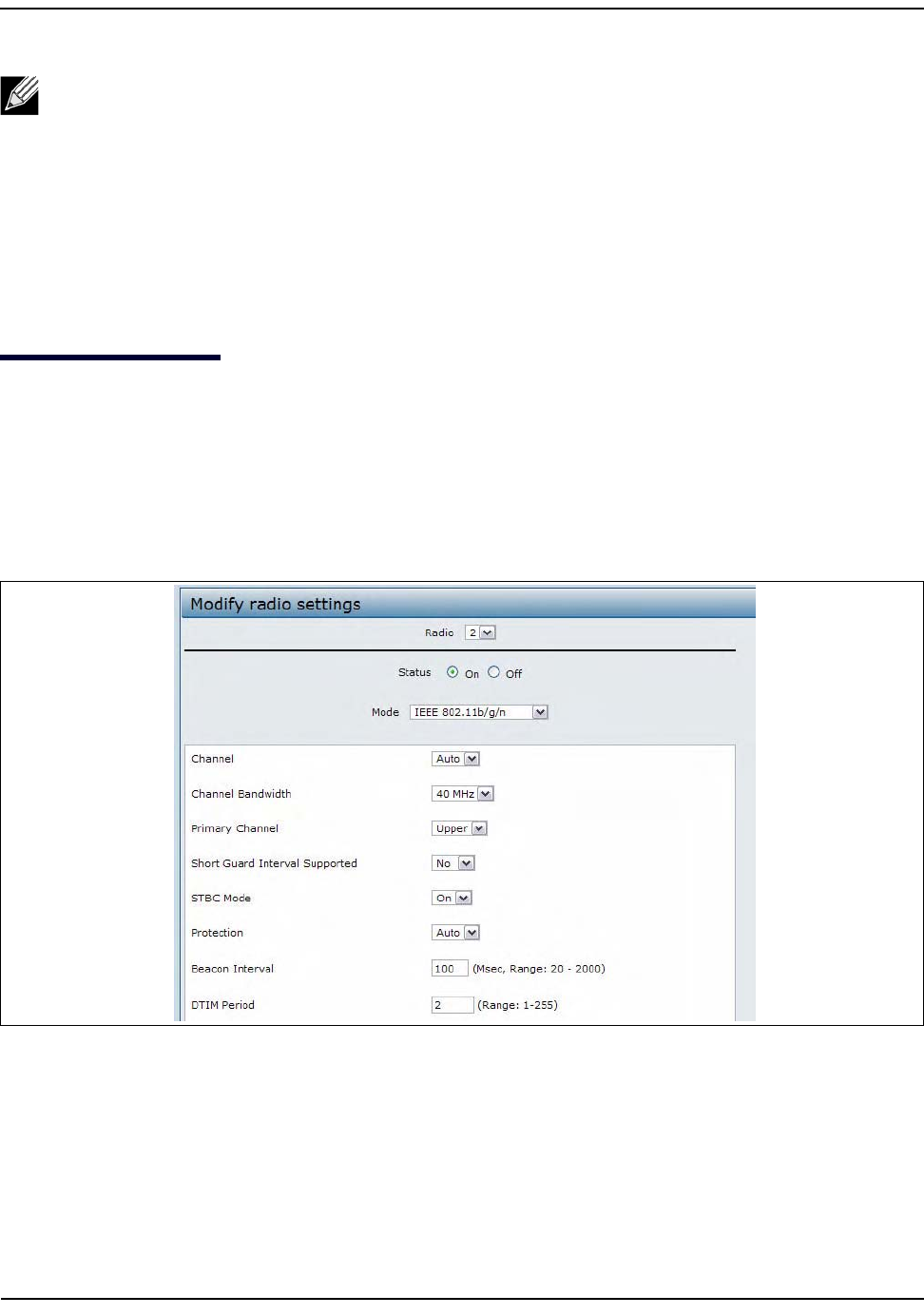
ModifyingRadioSettings
D-Link UnifiedAccessPointAdministrator’sGuide
November2011 Page58
UnifiedAccessPointAdministrator’sGuide
ModifyingRadioSettings
RadiosettingsdirectlycontrolthebehavioroftheradiodevicesintheAPanditsinteractionwiththephysical
medium;thatis,howandwhattypeofelectromagneticwavestheAPemits.
Tospecifyradiosettings,clicktheRadiotabintheManagesection.
Differentsettingsdisplaydependingonthemodeyouselect.AllsettingsaredescribedinTable19onpage60.
Figure15:ConfiguringRadioSettings
Note:ThefollowingnotesapplytoAeroScoutproductandprotocolsupport:
•D‐LinkdoesnotsellAeroScoutproducts.ContactAeroScoutforAeroScouthardware,softwareor
deploymentinformation.
•TheAEprotocoldoesnotsupportanyauthenticationorencryptionbetweentheAEserverand
theaccesspoint.
•TheAEprotocolrequiresradiostooperateinpromiscuousmode.ThismeansthattheAPreceives
andprocessesallpacketsdetectedbytheradios,asopposedtoprocessingonlypacketsdestined
totheAPsBSSID.ThiscanaffectAPthroughput.
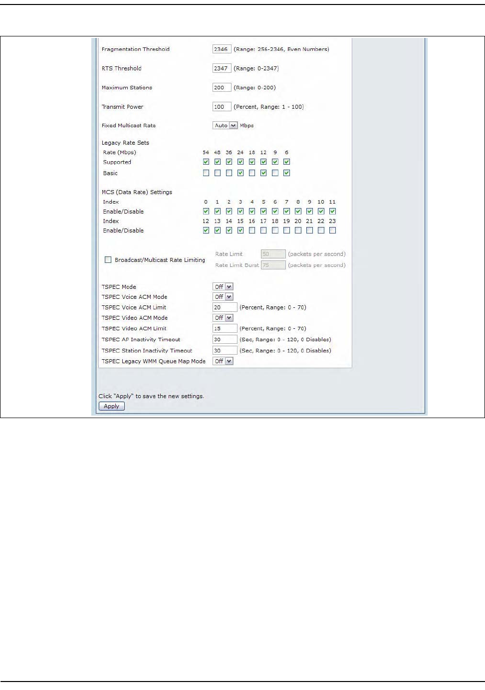
ModifyingRadioSettings
D-Link UnifiedAccessPointAdministrator’sGuide
November2011 Page59
UnifiedAccessPointAdministrator’sGuide
Figure16:ConfiguringRadioSettings(Continued)

ModifyingRadioSettings
D-Link UnifiedAccessPointAdministrator’sGuide
November2011 Page60
UnifiedAccessPointAdministrator’sGuide
Table19describesthefieldsandconfigurationoptionsfortheRadioSettingspage.
Note:TheDWL‐3600APsupportsonlyoneradio,anditoperatesinthe2.4GHzband(802.11b/g/n).
SomefieldsinthefollowingtablearenotavailablefortheDWL‐3600AP.
Table19:RadioSettings
Field Description
Radio SelectRadio1orRadio2tospecifywhichradiotoconfigure.Therestofthesettingson
thispageapplytotheradioyouselectinthisfield.Besuretoconfiguresettingsforboth
radios.
Radio1operatesinthe5GHzband(802.11a/n),andRadio2operatesinthe2.4GHz
band(802.11b/g/n).
Status(On/Off) SpecifywhetheryouwanttheradioonoroffbyclickingOnorOff.
Ifyouturnoffaradio,theAPsendsdisassociationframestoallthewirelessclientsitis
currentlysupportingsothattheradiocanbegracefullyshutdownandtheclientscan
starttheassociationprocesswithotheravailableAPs.
Mode TheModedefinesthePhysicalLayer(PHY)standardtheradiouses.
Note:Themodesavailabledependontheradioselected.
Selectoneofthefollowingmodesforradio1(DWL‐6600APandDWL‐8600APonly):
•IEEE802.11aisaPHYstandardthatspecifiesoperatinginthe5GHzU‐NIIbandusing
orthogonalfrequencydivisionmultiplexing(OFDM).Itsupportsdataratesranging
from6to54Mbps.
•IEEE802.11a/noperatesinthe5GHzISMbandandincludessupportforboth
802.11aand802.11ndevices.IEEE802.11nisanextensionofthe802.11standard
thatincludesmultiple‐inputmultiple‐output(MIMO)technology.IEEE802.11n
supportsdatarangesofupto248Mbpsandnearlytwicetheindoorrangeof802.11
b,802.11g,and802.11a.
•5GHzIEEE802.11nistherecommendedmodefornetworkswith802.11ndevices
thatoperateinthe5GHzfrequencythatdonotneedtosupport802.11adevices.
IEEE802.11ncanachieveahigherthroughputwhenitdoesnotneedtobe
compatiblewithlegacydevices(802.11a).
Selectoneofthefollowingmodesforradio2:
•IEEE802.11b/goperatesinthe2.4GHzISMband.IEEE802.11bisanenhancement
oftheinitial802.11PHYtoinclude5.5Mbpsand11Mbpsdatarates.Itusesdirect
sequencespreadspectrum(DSSS)orfrequencyhoppingspreadspectrum(FHSS)as
wellascomplementarycodekeying(CCK)toprovidethehigherdatarates.Itsupports
dataratesrangingfrom1to11Mbps.IEEE802.11gisahigherspeedextension(up
to54Mbps)tothe802.11bPHY.Itusesorthogonalfrequencydivisionmultiplexing
(OFDM).Itsupportsdataratesrangingfrom1to54Mbps.
•IEEE802.11b/g/noperatesinthe2.4GHzISMbandandincludessupportfor
802.11b,802.11g,and802.11ndevices.
•2.4GHzIEEE802.11nistherecommendedmodefornetworkswith802.11ndevices
thatoperateinthe2.4GHzfrequencythatdonotneedtosupport802.11b/gdevices.
IEEE802.11ncanachieveahigherthroughputwhenitdoesnotneedtobe
compatiblewithlegacydevices(802.11b/g).

ModifyingRadioSettings
D-Link UnifiedAccessPointAdministrator’sGuide
November2011 Page61
UnifiedAccessPointAdministrator’sGuide
Channel SelecttheChannel.
Therangeofavailablechannelsisdeterminedbythemodeoftheradiointerface.
If youselect Auto forthechannelsetting,theAP scansavailable hannels.and selects a
channel wherenotraffic isdetected.
Thechanneldefinestheportionoftheradiospectrumtheradiousesfortransmittingand
receiving.Eachmodeoffersanumberofchannels,dependingonhowthespectrumis
licensedbynationalandtransnationalauthoritiessuchastheFederalCommunications
Commission(FCC)ortheInternationalTelecommunicationUnion(ITU‐R).
WhenautomaticchannelassignmentisenabledontheChannelManagementpagefor
Clustering,thechannelpolicyfortheradioisautomaticallysettostaticmode,andthe
AutooptionisnotavailablefortheChannelfield.Thisallowstheautomaticchannel
featuretosetthechannelsfortheradiosinthecluster.
ChannelBandwidth
(802.11nmodes
only)
The802.11nspecificationallowsa40‐MHz‐widechannelinadditiontothelegacy20‐
MHzchannelavailablewithothermodes.The40‐MHzchannelenableshigherdatarates
butleavesfewerchannelsavailableforusebyother2.4GHzand5GHzdevices.
Setthefieldto20‐MHztorestricttheuseofthechannelbandwidthtoa20‐MHz
channel.
PrimaryChannel
(802.11nmodes
only)
Thissettingcanbechangedonlywhenthechannelbandwidthissetto40MHz.A40‐
MHzchannelcanbeconsideredtoconsistoftwo20‐MHzchannelsthatarecontiguous
inthefrequencydomain.Thesetwo20‐MHzchannelsareoftenreferredtoasthe
PrimaryandSecondarychannels.ThePrimaryChannelisusedfor802.11nclientsthat
supportonlya20‐MHzchannelbandwidthandforlegacyclients.
Selectoneofthefollowingoptions:
• Upper—SetthePrimaryChannelastheupper20‐MHzchannelinthe40‐MHzband.
•Lowe
r—SetthePrimaryChannelasthelower20‐MHzchannelinthe40‐MHzband.
ShortGuard
IntervalSupported
Thisfieldisavailableonlyiftheselectedradiomodeincludes802.11n.
Theguardintervalisthedeadtime,innanoseconds,betweenOFDMsymbols.Theguard
intervalpreventsInter‐SymbolandInter‐CarrierInterference(ISI,ICI).The802.11nmode
allowsforareductioninthisguardintervalfromtheaandgdefinitionof800
nanosecondsto400nanoseconds.Reducingtheguardintervalcanyielda10%
improvementindatathroughput.
Selectoneofthefollowingoptions:
•Yes—TheAPtransmitsdatausinga400nsguardIntervalwhencommunicatingwith
clientsthatalsosupporttheshortguardinterval.
•No—TheAPtransmitsdatausingan800nsguardinterval.
STBCMode Thisfieldisavailableonlyiftheselectedradiomodeincludes802.11n.
SpaceTimeBlockCoding(STBC)isan802.11ntechniqueintendedtoimprovethe
reliabilityofdatatransmissions.Thedatastreamistransmittedonmultipleantennasso
thereceivingsystemhasabetterchanceofdetectingatleastoneofthedatastreams.
Selectoneofthefollowingoptions:
•On—TheAPtransmitsthesamedatastreamonmultipleantennasatthesametime.
•Off—TheAPdoesnottransmitsthesamedataonmultipleantennas.
Table19:RadioSettings(Cont.)
Field Description

ModifyingRadioSettings
D-Link UnifiedAccessPointAdministrator’sGuide
November2011 Page62
UnifiedAccessPointAdministrator’sGuide
ProtectionTheprotectionfeaturecontainsrulestoguaranteethat802.11ntransmissionsdonot
causeinterferencewithlegacystationsorAPs.Bydefault,theseprotectionmechanisms
areenabled(Auto).Withprotectionenabled,protectionmechanismswillbeinvokedif
legacydevicesarewithinrangeoftheAP.Thiscausesmoreoverheadonevery
transmission,whichwillimpactperformance.However,thereisnoimpacton
performanceiftherearenolegacydeviceswithinrangeoftheAP.
Youcandisable(Off)theseprotectionmechanisms;however,when802.11nprotection
isoff,legacyclientsorAPswithinrangecanbeaffectedby802.11ntransmissions.The
802.11protectionfeatureisalsoavailablewhenthemodeis802.11b/g.When
protectionisenabledinthismode,itprotects802.11bclientsandAPsfrom802.11g
transmissions.
Note:ThissettingdoesnotaffecttheabilityoftheclienttoassociatewiththeAP.
BeaconInterval BeaconframesaretransmittedbyanAPatregularintervalstoannouncetheexistence
ofthewirelessnetwork.Thedefaultbehavioristosendabeaconframeonceevery100
milliseconds(or10persecond).
Enteravaluefrom20to2000milliseconds.
DTIMPeriod SpecifyaDTIMperiodfrom1to255beacons.
TheDeliveryTrafficInformationMap(DTIM)messageisanelementincludedinsome
Beaconframes.Itindicateswhichclientstations,currentlysleepinginlow‐powermode,
havedatabufferedontheAPawaitingpick‐up.
TheDTIMperiodyouspecifyindicateshowoftentheclientsservedbythisAPshould
checkforbuffereddatastillontheAPawaitingpickup.
Themeasurementisinbeacons.Forexample,ifyousetthisfieldto1,clientswillcheck
forbuffereddataontheAPateverybeacon.Ifyousetthisfieldto10,clientswillcheck
onevery10thbeacon.
Fragmentation
Threshold
Specifyanumberbetween256and2,346tosettheframesizethresholdinbytes.
Thefragmentationthresholdisawayoflimitingthesizeofpackets(frames)transmitted
overthenetwork.Ifapacketexceedsthefragmentationthresholdyouset,the
fragmentationfunctionisactivatedandthepacketissentasmultiple802.11frames.
Ifthepacketbeingtransmittedisequaltoorlessthanthethreshold,fragmentationisnot
used.
Settingthethresholdtothelargestvalue(2,346bytes)effectivelydisables
fragmentation.FragmentationplaysnorolewhenAggregationisenabled.
Fragmentationinvolvesmoreoverheadbothbecauseoftheextraworkofdividingup
andreassemblingofframesitrequires,andbecauseitincreasesmessagetrafficonthe
network.However,fragmentationcanhelpimprovenetworkperformanceandreliability
ifproperlyconfigured.
Sendingsmallerframes(byusinglowerfragmentationthreshold)mighthelpwithsome
interferenceproblems;forexample,withmicrowaveovens.
Bydefault,fragmentationisoff.Werecommendnotusingfragmentationunlessyou
suspectradiointerference.Theadditionalheadersappliedtoeachfragmentincreasethe
overheadonthenetworkandcangreatlyreducethroughput.
Table19:RadioSettings(Cont.)
Field Description
ModifyingRadioSettings
D-Link UnifiedAccessPointAdministrator’sGuide
November2011 Page63
UnifiedAccessPointAdministrator’sGuide
RTSThreshold SpecifyaRequesttoSend(RTS)Thresholdvaluebetween0and2347.
TheRTSthresholdindicatesthenumberofoctetsinanMPDU,belowwhichanRTS/CTS
handshakeisnotperformed.
ChangingtheRTSthresholdcanhelpcontroltrafficflowthroughtheAP,especiallyone
withalotofclients.Ifyouspecifyalowthresholdvalue,RTSpacketswillbesentmore
frequently.Thiswillconsumemorebandwidthandreducethethroughputofthepacket.
Ontheotherhand,sendingmoreRTSpacketscanhelpthenetworkrecoverfrom
interferenceorcollisionswhichmightoccuronabusynetwork,oronanetwork
experiencingelectromagneticinterference.
MaximumStations SpecifythemaximumnumberofstationsallowedtoaccessthisAPatanyonetime.
Youcanenteravaluebetween0and200.
TransmitPower EnterapercentagevalueforthetransmitpowerlevelforthisAP.
Thedefaultvalue,whichis100%,canbemorecost‐efficientthanalowerpercentage
sinceitgivestheAPamaximumbroadcastrangeandreducesthenumberofAPsneeded.
Toincreasecapacityofthenetwork,placeAPsclosertogetherandreducethevalueof
thetransmitpower.ThishelpsreduceoverlapandinterferenceamongAPs.Alower
transmitpowersettingcanalsokeepyournetworkmoresecurebecauseweakerwireless
signalsarelesslikelytopropagateoutsideofthephysicallocationofyournetwork.
FixedMulticast
Rate
SelectthemulticasttraffictransmissionrateyouwanttheAPtosupport.
LegacyRateSets CheckthetransmissionratesetsyouwanttheAPtosupportandthebasicratesetsyou
wanttheAPtoadvertise:
•Ratesareexpressedinmegabitspersecond.
•SupportedRateSetsindicateratesthattheAPsupports.Youcancheckmultiplerates
(clickacheckboxtoselectorde‐selectarate).TheAPwillautomaticallychoosethe
mostefficientratebasedonfactorslikeerrorratesanddistanceofclientstations
fromtheAP.
•BasicRateSetsindicateratesthattheAPwilladvertisetothenetworkforthe
purposesofsettingupcommunicationwithotherAPsandclientstationsonthe
network.ItisgenerallymoreefficienttohaveanAPbroadcastasubsetofits
supportedratesets.
MCS(DataRate)
Settings(802.11n
modesonly)
ThisfieldshowstheModulationandCodingScheme(MCS)indexvaluessupportedby
theradio.Eachindexcanbeenabledanddisabledindependently.
Broadcast/
MulticastRate
Limiting
Enablingmulticastandbroadcastratelimitingcanimproveoverallnetworkperformance
bylimitingthenumberofpacketstransmittedacrossthenetwork.
BydefaulttheMulticast/BroadcastRateLimitingoptionisdisabled.Untilyouenable
Multicast/BroadcastRateLimiting,thefollowingfieldswillbedisabled.
Broadcast/
MulticastRateLimit
Entertheratelimityouwanttosetformulticastandbroadcasttraffic.Thelimitshould
begreaterthan1,butlessthan50packetspersecond.Anytrafficthatfallsbelowthis
ratelimitwillalwaysconformandbetransmittedtotheappropriatedestination.
Thedefaultandmaximumratelimitsettingis50packetspersecond.
Broadcast/
MulticastRateLimit
Burst
Settingaratelimitburstdetermineshowmuchtrafficburstscanbebeforealltraffic
exceedstheratelimit.Thisburstlimitallowsintermittentburstsoftrafficonanetwork
abovethesetratelimit.
Thedefaultandmaximumratelimitburstsettingis75packetspersecond.
Table19:RadioSettings(Cont.)
Field Description
ModifyingRadioSettings
D-Link UnifiedAccessPointAdministrator’sGuide
November2011 Page64
UnifiedAccessPointAdministrator’sGuide
UsetheRadiopagetoconfigurebothRadioOneandRadioTwo.Thesettingsonthepageapplyonlytothe
radiothatyouchoosefromtheRadiodrop‐downlist.Afteryouconfiguresettingsforoneoftheradios,click
Applyandthenselectandconfiguretheotherradio.BesuretoclickApplytoapplythesecondsetof
configurationsettingsfortheotherradio.
TSPECMode RegulatestheoverallTSPECmodeontheAP.Theoptionsare:
•On—TheAPhandlesTSPECrequestsaccordingtotheTSPECsettingsyouconfigure
ontheRadiopage.UsethissettingiftheAPhandlestrafficfromQoS‐capable
devices,suchasaWi‐FiCERTIFIEDphone.
•Off—TheAPignoresTSPECrequestsfromclientstations.Usethissettingifyoudo
notwanttouseTSPECtogiveQoS‐capabledevicespriorityfortime‐sensitivetraffic.
TSPECVoiceACM
Mode
Regulatesmandatoryadmissioncontrol(ACM)forthevoiceaccesscategory.Theoptions
are:
•On—AstationisrequiredtosendaTSPECrequestforbandwidthtotheAPbefore
sendingorreceivingavoicetrafficstream.TheAPrespondswiththeresultofthe
request,whichincludestheallottedmediumtimeiftheTSPECwasadmitted.
•Off—Astationcansendandreceivevoiceprioritytrafficwithoutrequiringan
admittedTSPEC;theAPignoresvoiceTSPECrequestsfromclientstations.
TSPECVoiceACM
Limit
SpecifyanupperlimitontheamountoftraffictheAPattemptstotransmitonthe
wirelessmediumusingavoiceACtogainaccess.
TSPECVideoACM
Mode
Regulatesmandatoryadmissioncontrolforthevideoaccesscategory.Theoptionsare:
•On—AstationisrequiredtosendaTSPECrequestforbandwidthtotheAPbefore
sendingorreceivingavideotrafficstream.TheAPrespondswiththeresultofthe
request,whichincludestheallottedmediumtimeiftheTSPECwasadmitted.
•Off—Astationcansendandreceivevideoprioritytrafficwithoutrequiringan
admittedTSPEC;theAPignoresvideoTSPECrequestsfromclientstations.
TSPECVideoACM
Limit
SpecifyanupperlimitontheamountoftraffictheAPattemptstotransmitonthe
wirelessmediumusingavideoACtogainaccess.
TSPECAPInactivity
Timeout
SpecifytheamountoftimeforanAPtodetectandownlinkTSasidlebeforedeletingit.
TSPECStation
InactivityTimeout
SpecifytheamountoftimeforanAPtodetectanuplinkTSasidlebeforedeletingit.
TSPECLegacyWMM
QueueMapMode
SelectEnabletoallowintermixingoflegacytrafficonqueuesoperatingasACM.
Table19:RadioSettings(Cont.)
Field Description
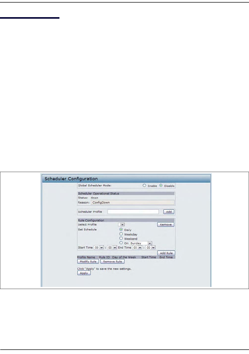
ConfiguringRadioandVAPScheduler
D-Link UnifiedAccessPointAdministrator’sGuide
November2011 Page65
UnifiedAccessPointAdministrator’sGuide
ConfiguringRadioandVAPScheduler
TheRadioandVAPschedulerisastandaloneDWL‐x600APfeature.ToconfiguretheRadioandVAPscheduler,
selecttheSchedulertabintheManagesection.TheRadioandVAPSchedulerallowsyoutoconfigurearule
withaspecifictimeintervalforVAPsorradiostobeoperational,therebyautomatingtheenablingordisabling
oftheVAPsandRadios.
Oneofthewaysyoucanusethisfeatureistoscheduleradiostooperateonlyduringtheofficeworkinghours
inordertoachievesecurityandreducepowerconsumption.YoucanalsousetheSchedulertoallowaccessto
VAPsforwirelessclientsonlyduringspecifictimesofday.
Eachrulespecifiesthestarttime,endtimeandday(ordays)oftheweektheradioorVAPcanbeoperational.
Therulesareperiodicinnatureandarerepeatedeveryweek.
Avalidrulemustcontainallofthefollowingparameters:
•D
aysoftheWeek
•StartTime(hourandminutes)
•EndTime(hourandminutes)
Onlyvalidrulesareaddedtotheprofile.Upto16rulesaregroupedtogethertoformaschedulingprofile.Any
twoperiodicrulestimeentriesbelongingtothesameprofilemustnotoverlap.Thetimegranularityforthe
schedulesisoneminute.TheDWL‐x600APsupportsupto16profiles.
Figure17:SchedulerConfiguration
ConfiguringRadioandVAPScheduler
D-Link UnifiedAccessPointAdministrator’sGuide
November2011 Page66
UnifiedAccessPointAdministrator’sGuide
Table20:SchedulerConfiguration
Field Description
GlobalSchedulerMode Aglobalswitchtoenableordisabletheschedulerfeature.ThedefaultisDisable.
SchedulerOperationalStatus
Status TheoperationalstatusoftheScheduler.TherangeisUporDown.Thedefaultis
Down.
Reason Providesadditionalinformationaboutthestatus.Thereasoncanbeoneormoreof
thefollowing:
• IsActive–Operationalstatusisup.
• ConfigDown–Operationalstatusisdownbecauseglobalconfigurationis
disabled.
• TimeNotSet–OperationalstatusisdownbecausetheAPtimehasnotbeenset,
eithermanuallyorbyspecifyinganNTPservertouse.
•ManagedMode–OperationalstatusisdownbecausetheAPisinmanaged
mode.
SchedulerProfile TheSchedulerprofiledefinesthelistofprofilesnamesthatcanbeassociatedtothe
VAPorRadioconfiguration.Rulesareassociatedwithanamedschedulerprofile.You
candefineupto16schedulerprofilenames.Bydefault,noprofilesarecreated.
Theprofilenamecanbeupto32alphanumericcharacters.ClickAddtoaddthe
profilename.
Rule Configuration Eachschedulerprofilemayhaveupto16periodicrules.Thelistofparametersfor
eachperiodicrulearedescribedbelow.
SelectProfile Selecttheprofilenamefromthemenu.
SetSchedule Thedayoftheweek.Rangeis:Daily,Weekday(MondaytoFriday),Weekend
(SaturdayandSunday),Monday,Tuesday,Wednesday,Thursday,Friday,Saturday,
Sunday.ThedefaultisDaily.
StartTime ThetimewhentheradioorVAPwillbeoperationallyenabled.ThetimeisinHH:MM
24‐hourformat.Therangeis<00‐24>:<00‐59>.Thedefaultis00:00.
EndTime ThetimewhentheradioorVAPwillbeoperationallydisabled.ThetimeisinHH:MM
24‐hourformat.Therangeis<00‐24>:<00‐59>.Thedefaultis00:00.
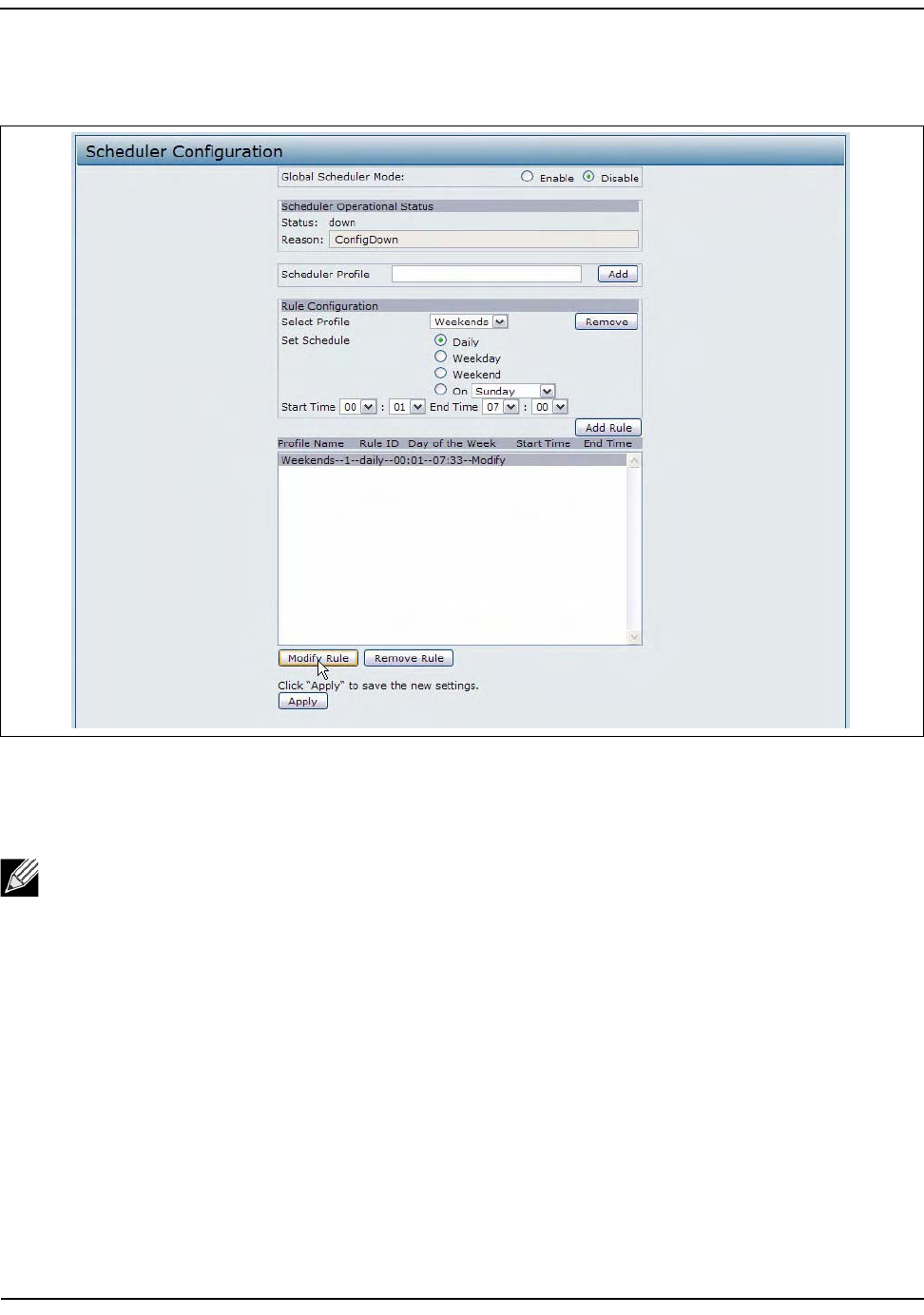
ConfiguringRadioandVAPScheduler
D-Link UnifiedAccessPointAdministrator’sGuide
November2011 Page67
UnifiedAccessPointAdministrator’sGuide
Tochangeanexistingrule,selecttherule,updatethevaluesintheRuleConfigurationarea,andclickModify
Rule.
Figure18:ModifyRuleConfiguration
ClickApplytosavethenewconfigurationsettings.
Note:Aftermakinganymodifications,youmustclickApplytoapplythechangesandtosavethe
settings.
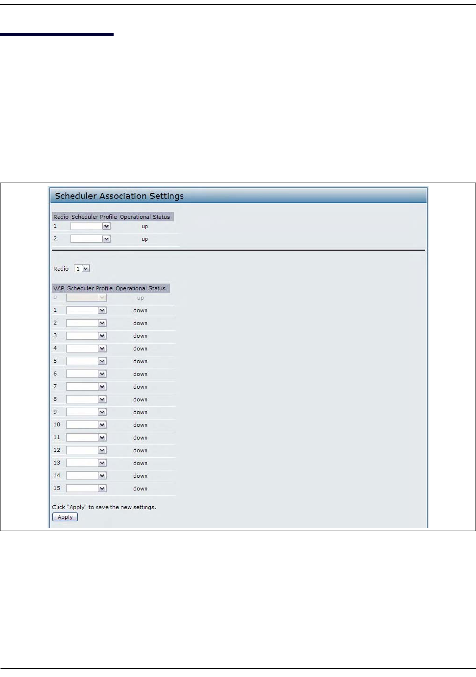
SchedulerAssociationSettings
D-Link UnifiedAccessPointAdministrator’sGuide
November2011 Page68
UnifiedAccessPointAdministrator’sGuide
SchedulerAssociationSettings
ForaSchedulerprofiletotakeeffect,youmustassociateitwithatleastoneradioorVAPinterface.Toassociate
theSchedulerprofiles,selecttheSchedulerAssociationtabintheManagesection.Bydefault,thereareno
Schedulerprofilescreated,sonoprofileisassociatedtoanyradioorVAP.TheSchedulerprofileneedstobe
explicitlyassociatedtoaradioorVAPconfiguration.OnlyoneSchedulerprofilecanbeassociatedtoanyradio
orVAPconfiguration;however,asingleprofilecanbeassociatedtomultipleradiosorVAPs.IftheScheduler
profileassociatedwithaVAPorradioisdeleted,thentheassociatedprofiletotheVAPorradioisremoved
implicitly.Iftheradioisoperationallydisabled,thenalltheVAPsassociatedtothatradioarealsooperationally
disabledirrespectiveoftheVAPconfiguration.
Figure19:SchedulerAssociation

SchedulerAssociationSettings
D-Link UnifiedAccessPointAdministrator’sGuide
November2011 Page69
UnifiedAccessPointAdministrator’sGuide
Table21:SchedulerAssociationSettings
Field Description
RadioSchedulerProfileOperationalStatus
1or2Fromthemenu,selecttheSchedulerprofiletoassociatewithRadio1orRadio2.
Note:TheDWL‐3600APsupportsonlyoneradio.
Status TheoperationalstatusoftheScheduler.TherangeisUporDown.
VAPSchedulerProfileOperationalStatus
Radio Fromthemenu,selectRadio1orRadio2toassociatetheVAPSchedulerProfile.
Note:ThisfieldisnotavailableontheDWL‐3600AP.
0‐15 Fromthemenu,selecttheSchedulerprofiletoassociatewiththerespectiveVAP.
Status TheoperationalstatusoftheScheduler.TherangeisUporDown.
Note:AfteryouassociateaSchedulerprofilewithaRadiointerfaceoraVAPinterface,youmustclick
Applytoapplythechangesandtosavethesettings.

VirtualAccessPointSettings
D-Link UnifiedAccessPointAdministrator’sGuide
November2011 Page70
UnifiedAccessPointAdministrator’sGuide
VirtualAccessPointSettings
TochangeVAP0ortoenableandconfigureadditionalVAPs,selecttheVAPtabintheManagesection.
VAPssegmentthewirelessLANintomultiplebroadcastdomainsthatarethewirelessequivalentofEthernet
VLANs.VAPssimulatemultipleAPsinonephysicalAP.Eachradiosupportsupto16VAPs.
ForeachVAP,youcancustomizethesecuritymodetocontrolwirelessclientaccess.EachVAPcanalsohavea
uniqueSSID.MultipleSSIDsmakeasingleAPlookliketwoormoreAPstoothersystemsonthenetwork.By
configuringVAPs,youcanmaintainbettercontroloverbroadcastandmulticasttraffic,whichaffectsnetwork
performance.
YoucanconfigureeachVAPtouseadifferentVLAN,oryoucanconfiguremultipleVAPstousethesameVLAN,
whethertheVLANisonthesameradiooronadifferentradio.VAP0,whichisalwaysenabledonbothradios,
isassignedtothedefaultVLAN1.
TheAPaddsVLANIDtagstowirelessclienttrafficbasedontheVLANIDyouconfigureontheVAPpageorby
usingtheRADIUSserverassignment.IfyouuseanexternalRADIUSserver,youcanconfiguremultipleVLANs
oneachVAP.TheexternalRADIUSserverassignswirelessclientstotheVLANwhentheclientsassociateand
authenticate.
YoucanconfigureuptofourglobalIPv4orIPv6RADIUSservers.Oneoftheserversalwaysactsasaprimary
whiletheothersactasbackupservers.Thenetworktype(IPv4orIPv6)andaccountingmodearecommon
acrossallconfiguredRADIUSservers.YoucanconfigureeachVAPtousetheglobalRADIUSserversettings,
whichisthedefault,oryoucanconfigureaper‐VAPRADIUSserverset.YoucanalsoconfigureseparateRADIUS
serversettingsforeachVAP.Forexample,youcanconfigureoneVAPtouseanIPv6RADIUSserverwhileother
VAPsusetheglobalIPv4RADIUSserversettingsyouconfigure.
IfwirelessclientsuseasecuritymodethatdoesnotcommunicatewiththeRAIDUSserver,oriftheRADIUS
serverdoesnotprovidetheVLANinformation,youcanassignaVLANIDtoeachVAP.TheAPassignstheVLAN
toallwirelessclientsthatconnecttotheAPthroughthatVAP.
TosetupmultipleVAPs,clickManage>VAP.
Note:BeforeyouconfigureVLANsontheAP,besuretoverifythattheswitchandDHCPservertheAP
usescansupportIEEE802.1QVLANencapsulation.
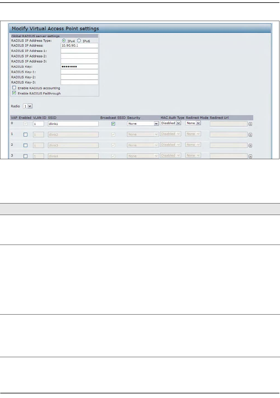
VirtualAccessPointSettings
D-Link UnifiedAccessPointAdministrator’sGuide
November2011 Page71
UnifiedAccessPointAdministrator’sGuide
Figure20:SettingUpVirtualAccessPoints
Table22describesthefieldsandconfigurationoptionsontheVAPpage.
Table22:VirtualAccessPointSettings
Field Description
RADIUSIPAddress
Type
SpecifytheIPversionthattheRADIUSserveruses.
YoucantogglebetweentheaddresstypestoconfigureIPv4andIPv6globalRADIUS
addresssettings,buttheAPcontactsonlytheRADIUSserverorserversfortheaddress
typeyouselectinthisfield.
RADIUSIPAddress
RADIUSIPv6
Address
EntertheIPv4orIPv6addressfortheprimaryglobalRADIUSserver.Bydefault,eachVAP
usestheglobalRADIUSsettingsthatyoudefinefortheAPatthetopoftheVAPpage.
WhenthefirstwirelessclienttriestoauthenticatewiththeAP,theAPsendsan
authenticationrequesttotheprimaryserver.Iftheprimaryserverrespondstothe
authenticationrequest,theAPcontinuestousethisRADIUSserverastheprimaryserver,
andauthenticationrequestsaresenttotheaddressyouspecify.
IftheIPv4RADIUSIPAddressTypeoptionisselectedinthepreviousfield,entertheIP
addressoftheRADIUSserverthatallVAPsusebydefault,forexample192.168.10.23.If
theIPv6RADIUSIPAddressTypeoptionisselected,entertheIPv6addressoftheprimary
globalRADIUSserver,forexample2001:0db8:1234::abcd.
RADIUSIPorIPv6
Address1–3
EnteruptothreeIPv4orIPv6addressestouseasthebackupRADIUSservers.Thefield
labelisRADIUSIPAddresswhentheIPv4RADIUSIPAddressTypeoptionisselectedand
RADIUSIPv6AddresswhentheIPv6RADIUSIPAddressTypeoptionisselected.
Ifauthenticationfailswiththeprimaryserver,eachconfiguredbackupserveristriedin
sequence.TheIPv4orIPv6addressmustbevalidinorderfortheAPtoattemptto
contacttheserver.

VirtualAccessPointSettings
D-Link UnifiedAccessPointAdministrator’sGuide
November2011 Page72
UnifiedAccessPointAdministrator’sGuide
RADIUSKey EntertheRADIUSkeyinthetextbox.
TheRADIUSKeyisthesharedsecretkeyfortheglobalRADIUSserver.Youcanuseupto
63standardalphanumericandspecialcharacters.Thekeyiscasesensitive,andyoumust
configurethesamekeyontheAPandonyourRADIUSserver.Thetextyouenterwillbe
displayedas“*”characterstopreventothersfromseeingtheRADIUSkeyasyoutype.
RADIUSKey1–3EntertheRADIUSkeyassociatedwiththeconfiguredbackupRADIUSservers.Theserver
atRADIUSIPAddress‐1usesRADIUSKey‐1,RADIUSIPAddress‐2usesRADIUSKey‐2,and
soon.
EnableRADIUS
Accounting
Selectthisoptiontotrackandmeasuretheresourcesaparticularuserhasconsumed
suchassystemtime,amountofdatatransmittedandreceived,andsoon.
IfyouenableRADIUSaccounting,itisenabledfortheprimaryRADIUSserverandall
backupservers.
EnableRADIUS
FailThrough
SelectthisoptiontoallowthesecondaryRADIUSservertoauthenticatewirelessclients
iftheauthenticationwiththeprimaryRADIUSserverisunsuccessful,oriftheprimary
RADIUSserverisunavailable.
Radio Selecttheradiotoconfigure.VAPsareconfiguredindependentlyoneachradio.
Note:TheDWL‐3600APsupportsonlyoneradio.
VAP Youcanconfigureupto16VAPsforeachradio.VAP0isthephysicalradiointerface,soto
disableVAP0,youmustdisabletheradio.
Enabled Youcanenableordisableaconfigurednetwork.
•Toenablethespecifiednetwork,selecttheEnabledoptionbesidetheappropriate
VAP.
•Todisablethespecifiednetwork,cleartheEnabledoptionbesidetheappropriate
VAP.
Ifyoudisablethespecifiednetwork,youwilllosetheVLANIDyouentered.
VLANID WhenawirelessclientconnectstotheAPbyusingthisVAP,theAPtagsalltrafficfrom
thewirelessclientwiththeVLANIDyouenterinthisfieldunlessyouentertheuntagged
VLANIDoruseaRADIUSservertoassignawirelessclienttoaVLAN.Therangeforthe
VLANIDis1–4094.
IfyouuseRADIUS‐basedauthenticationforclients,youcanoptionallyaddthefollowing
attributestotheappropriatefileintheRADIUSorAAAservertoconfigureaVLANforthe
client:
• “Tunnel‐Type”
• “Tunnel‐Medium‐Type”
• “Tunnel‐Private‐Group‐ID”
TheRADIUS‐assignedVLANIDoverridestheVLANIDyouconfigureontheVAPpage.
YouconfiguretheuntaggedandmanagementVLANIDsontheEthernetSettingspage.
Formoreinformation,see“EthernetSettings”onpage51.
SSID Enteranameforthewirelessnetwork.TheSSIDisanalphanumericstringofupto32
characters.YoucanusethesameSSIDformultipleVAPs,oryoucanchooseauniqueSSID
foreachVAP.
Note:IfyouareconnectedasawirelessclienttothesameAPthatyouareadministering,
resettingtheSSIDwillcauseyoutoloseconnectivitytotheAP.Youwillneedtoreconnect
tothenewSSIDafteryousavethisnewsetting.
Table22:VirtualAccessPointSettings(Cont.)
Field Description

VirtualAccessPointSettings
D-Link UnifiedAccessPointAdministrator’sGuide
November2011 Page73
UnifiedAccessPointAdministrator’sGuide
BroadcastSSID SpecifywhethertoallowtheAPtobroadcasttheServiceSetIdentifier(SSID)inits
beaconframes.TheBroadcastSSIDparameterisenabledbydefault.WhentheVAPdoes
notbroadcastitsSSID,thenetworknameisnotdisplayedinthelistofavailablenetworks
onaclientstation.Instead,theclientmusthavetheexactnetworknameconfiguredin
thesupplicantbeforeitisabletoconnect.
•ToenabletheSSIDbroadcast,selecttheBroadcastSSIDcheckbox.
•ToprohibittheSSIDbroadcast,cleartheBroadcastSSIDcheckbox.
Note:DisablingthebroadcastSSIDissufficienttopreventclientsfromaccidentally
connectingtoyournetwork,butitwillnotpreventeventhesimplestofattemptsbya
hackertoconnectormonitorunencryptedtraffic.SuppressingtheSSIDbroadcastoffers
averyminimallevelofprotectiononanotherwiseexposednetwork(suchasaguest
network)wherethepriorityismakingiteasyforclientstogetaconnectionandwhere
nosensitiveinformationisavailable.
Security SelectoneofthefollowingSecuritymodesforthisVAP:
•None
•StaticWEP
•WPAPersonal
• IEEE802.1X
•WPAEnterprise
IfyouselectasecuritymodeotherthanNone,additionalfieldsappear.Thesefieldsare
explainedbelow.
Note:TheSecuritymodeyousethereisspecificallyforthisVAP.
MAC
Authentication
Type
YoucanconfigureagloballistofMACaddressesthatareallowedordeniedaccesstothe
network.Thedrop‐downmenuforthisfeatureallowsyoutoselectthetypeofMAC
Authenticationtouse:
• Disabled:DonotuseMACAuthentication.
•Local:UsetheMACAuthenticationlistthatyouconfigureontheMACAuthentication
page.
•RADIUS:UsetheMACAuthenticationlistontheexternalRADIUSserver.
FormoreinformationaboutMACAuthentication,see“ControllingAccessbyMAC
Authentication”onpage85.
RedirectMode EnabletheHTTPredirectfeaturetoredirectwirelessclientstoacustomWebpage.
Whenredirectmodeisenabled,theuserwillberedirectedtotheURLyouspecifyafter
thewirelessclientassociateswithanAPandtheuseropensaWebbrowserontheclient
toaccesstheInternet.
ThecustomWebpagemustbelocatedonanexternalWebserverandmightcontain
informationsuchasthecompanylogoandnetworkusagepolicy.
Note:ThewirelessclientisredirectedtotheexternalWebserveronlyoncewhileitis
associatedwiththeAP.
RedirectURL SpecifytheURLwheretheWebbrowseristoberedirectedafterthewirelessclient
associateswiththeAPandsendsHTTPtraffic.
Table22:VirtualAccessPointSettings(Cont.)
Field Description

VirtualAccessPointSettings
D-Link UnifiedAccessPointAdministrator’sGuide
November2011 Page74
UnifiedAccessPointAdministrator’sGuide
None(Plain‐text)
IfyouselectNoneasyoursecuritymode,nofurtheroptionsareconfigurableontheAP.Thismodemeansthat
anydatatransferredtoandfromtheUAPisnotencrypted.Thissecuritymodecanbeusefulduringinitial
networkconfigurationorforproblemsolving,butitisnotrecommendedforregularuseontheInternal
networkbecauseitisnotsecure.
StaticWEP
WiredEquivalentPrivacy(WEP)isadataencryptionprotocolfor802.11wirelessnetworks.Allwirelessstations
andAPsonthenetworkareconfiguredwithastatic64‐bit(40‐bitsecretkey+24‐bitinitializationvector(IV))
or128‐bit(104‐bitsecretkey+24‐bitIV)SharedKeyfordataencryption.
StaticWEPisnotthemostsecuremodeavailable,butitoffersmoreprotectionthansettingthesecuritymode
toNone(Plain‐text)asitdoespreventanoutsiderfromeasilysniffingoutunencryptedwirelesstraffic.
WEPencryptsdatamovingacrossthewirelessnetworkbasedonastatickey.(Theencryptionalgorithmisa
streamciphercalledRC4.)
Note:AfteryouconfiguretheVAPsettings,youmustclickApplytoapplythechangesandtosavethe
settings.ChangingsomesettingsmightcausetheAPtostopandrestartsystemprocesses.Ifthis
happens,wirelessclientswilltemporarilyloseconnectivity.WerecommendthatyouchangeAP
settingswhenWLANtrafficislow.
Table23:StaticWEP
Field Description
TransferKeyIndex Selectakeyindexfromthedrop‐downmenu.Keyindexes1through4areavailable.The
defaultis1.
TheTransferKeyIndexindicateswhichWEPkeytheAPwillusetoencryptthedatait
transmits.
KeyLength Specifythelengthofthekeybyclickingoneoftheradiobuttons:
•64bits
• 128bits
KeyType Selectthekeytypebyclickingoneoftheradiobuttons:
•ASCII
•Hex

VirtualAccessPointSettings
D-Link UnifiedAccessPointAdministrator’sGuide
November2011 Page75
UnifiedAccessPointAdministrator’sGuide
WEPKeys YoucanspecifyuptofourWEPkeys.Ineachtextbox,enterastringofcharactersforeach
key.Thekeysyouenterdependonthekeytypeselected:
•ASCII—Includesupperandlowercasealphabeticletters,thenumericdigits,and
specialsymbolssuchas@and#.
•H
ex—Includesdigits0to9andthelettersAtoF.
UsethesamenumberofcharactersforeachkeyasspecifiedintheCharactersRequired
field.ThesearetheRC4WEPkeyssharedwiththestationsusingtheAP.
EachclientstationmustbeconfiguredtouseoneofthesesameWEPkeysinthesame
slotasspecifiedhereontheAP.
CharactersRequired:ThenumberofcharactersyouenterintotheWEPKeyfieldsis
determinedbytheKeylengthandKeytypeyouselect.Forexample,ifyouuse128‐bit
ASCIIkeys,youmustenter26charactersintheWEPkey.Thenumberofcharacters
requiredupdatesautomaticallybasedonhowyousetKeyLengthandKeyType.
AuthenticationTheauthenticationalgorithmdefinesthemethodusedtodeterminewhetheraclient
stationisallowedtoassociatewithanAPwhenstaticWEPisthesecuritymode.
Specifytheauthenticationalgorithmyouwanttousebychoosingoneofthefollowing
options:
•OpenSystemauthenticationallowsanyclientstationtoassociatewiththeAP
whetherthatclientstationhasthecorrectWEPkeyornot.Thisalgorithmisalsoused
inplaintext,IEEE802.1X,andWPAmodes.Whentheauthenticationalgorithmisset
toOpenSystem,anyclientcanassociatewiththeAP.
Note:Justbecauseaclientstationisallowedtoassociatedoesnotensureitcan
exchangetrafficwithanAP.AstationmusthavethecorrectWEPkeytobeableto
successfullyaccessanddecryptdatafromanAP,andtotransmitreadabledatatotheAP.
•SharedKeyauthenticationrequirestheclientstationtohavethecorrectWEPkeyin
ordertoassociatewiththeAP.WhentheauthenticationalgorithmissettoShared
Key,astationwithanincorrectWEPkeywillnotbeabletoassociatewiththeAP.
•BothOpenSystemandSharedKey.Whenyouselectbothauthenticationalgorithms:
– ClientstationsconfiguredtouseWEPinsharedkeymodemusthaveavalidWEP
keyinordertoassociatewiththeAP.
– ClientstationsconfiguredtouseWEPasanopensystem(sharedkeymodenot
enabled)willbeabletoassociatewiththeAPeveniftheydonothavethecorrect
WEPkey.
Table23:StaticWEP(Cont.)
Field Description

VirtualAccessPointSettings
D-Link UnifiedAccessPointAdministrator’sGuide
November2011 Page76
UnifiedAccessPointAdministrator’sGuide
StaticWEPRules
IfyouuseStaticWEP,thefollowingrulesapply:
•AllclientstationsmusthavetheWirelessLAN(WLAN)securitysettoWEP,andallclientsmusthaveoneof
theWEPkeysspecifiedontheAPinordertode‐codeAP‐to‐stationdatatransmissions.
•TheAPmusthaveallkeysusedbyclientsforstation‐to‐APtransmitsothatitcande‐codethestation
transmissions.
•Thesamekeymustoccupythesameslotonallnodes(APandclients).ForexampleiftheAPdefines
abc123keyasWEPkey3,thentheclientstationsmustdefinethatsamestringasWEPkey3.
•Clientstationscanusedifferentkeystotransmitdatatotheaccesspoint.(Ortheycanallusethesame
key,butthisislesssecurebecauseitmeansonestationcandecryptthedatabeingsentbyanother.)
•Onsomewirelessclientsoftware,youcanconfiguremultipleWEPkeysanddefineaclientstation
“transferkeyindex”,andthensetthestationstoencryptthedatatheytransmitusingdifferentkeys.This
ensuresthatneighboringAPscannotdecodeeachother’stransmissions.
•Youcannotmix64‐bitand128‐bitWEPkeysbetweentheaccesspointanditsclientstations.
IEEE802.1X
IEEE802.1Xisthestandarddefiningport‐basedauthenticationandinfrastructurefordoingkeymanagement.
ExtensibleAuthenticationProtocol(EAP)messagessentoveranIEEE802.11wirelessnetworkusingaprotocol
calledEAPEncapsulationOverLANs(EAPOL).IEEE802.1Xprovidesdynamically‐generatedkeysthatare
periodicallyrefreshed.AnRC4streamcipherisusedtoencrypttheframebodyandcyclicredundancychecking
(CRC)ofeach802.11frame.
ThismoderequirestheuseofanexternalRADIUSservertoauthenticateusers.TheAPrequiresaRADIUS
servercapableofEAP,suchastheMicrosoftInternetAuthenticationServer.ToworkwithWindowsclients,the
authenticationservermustsupportProtectedEAP(PEAP)andMSCHAPV2.
YoucanuseanyofavarietyofauthenticationmethodsthattheIEEE802.1Xmodesupports,including
certificates,Kerberos,andpublickeyauthentication.Youmustconfiguretheclientstationstousethesame
authenticationmethodtheAPuses.
Table24:IEEE802.1X
Field Description
UseGlobalRADIUS
ServerSettings
BydefaulteachVAPusestheglobalRADIUSsettingsthatyoudefinefortheAPatthetop
oftheVAPpage.However,youcanconfigureeachVAPtouseadifferentsetofRADIUS
servers.
TousetheglobalRADIUSserversettings,makesurethecheckboxisselected.
TouseaseparateRADIUSserverfortheVAP,clearthecheckboxandentertheRADIUS
serverIPaddressandkeyinthefollowingfields.
RADIUSIPAddress
Type
SpecifytheIPversionthattheRADIUSserveruses.
YoucantogglebetweentheaddresstypestoconfigureIPv4andIPv6globalRADIUS
addresssettings,buttheAPcontactsonlytheRADIUSserverorserversfortheaddress
typeyouselectinthisfield.
VirtualAccessPointSettings
D-Link UnifiedAccessPointAdministrator’sGuide
November2011 Page77
UnifiedAccessPointAdministrator’sGuide
RADIUSIPAddress
RADIUSIPv6
Address
EntertheIPv4orIPv6addressfortheprimaryRADIUSserverforthisVAP.
IftheIPv4RADIUSIPAddressTypeoptionisselectedinthepreviousfield,entertheIP
addressoftheRADIUSserverthatallVAPsusebydefault,forexample192.168.10.23.If
theIPv6RADIUSIPAddressTypeoptionisselected,entertheIPv6addressoftheprimary
globalRADIUSserver,forexample2001:0db8:1234::abcd.
RADIUSIPorIPv6
Address1–3
EnteruptothreeIPv4and/orIPv6addressestouseasthebackupRADIUSserversforthis
VAP.ThefieldlabelisRADIUSIPAddresswhentheIPv4RADIUSIPAddressTypeoptionis
selectedandRADIUSIPv6AddresswhentheIPv6RADIUSIPAddressTypeoptionis
selected.
Ifauthenticationfailswiththeprimaryserver,eachconfiguredbackupserveristriedin
sequence.
RADIUSKey EntertheRADIUSkeyinthetextbox.
TheRADIUSKeyisthesharedsecretkeyfortheglobalRADIUSserver.Youcanuseupto
63standardalphanumericandspecialcharacters.Thekeyiscasesensitive,andyoumust
configurethesamekeyontheAPandonyourRADIUSserver.Thetextyouenterwillbe
displayedas“*”characterstopreventothersfromseeingtheRADIUSkeyasyoutype.
RADIUSKey1–3EntertheRADIUSkeyassociatedwiththeconfiguredbackupRADIUSservers.Theserver
atRADIUSIPAddress‐1usesRADIUSKey‐1,RADIUSIPAddress‐2usesRADIUSKey‐2,and
soon.
EnableRADIUS
Accounting
Selectthisoptiontotrackandmeasuretheresourcesaparticularuserhasconsumed
suchassystemtime,amountofdatatransmittedandreceived,andsoon.
IfyouenableRADIUSaccounting,itisenabledfortheprimaryRADIUSserverandall
backupservers.
EnableRADIUS
FailThrough
SelectthisoptiontoallowthesecondaryRADIUSservertoauthenticatewirelessclients
iftheauthenticationwiththeprimaryRADIUSserverisunsuccessful,oriftheprimary
RADIUSserverisunavailable.
ActiveServer SpecifywhichconfiguredRADIUSservertouseastheactiveRADIUSserver.
BroadcastKey
RefreshRate
Enteravaluetosettheintervalatwhichthebroadcast(group)keyisrefreshedforclients
associatedtothisVAP(thedefaultis300).
Thevalidrangeis0–86400seconds.Avalueof0indicatesthatthebroadcastkeyisnot
refreshed.
SessionKeyRefresh
Rate
EnteravaluetosettheintervalatwhichtheAPwillrefreshsession(unicast)keysforeach
clientassociatedtotheVAP.
Thevalidrangeis0–86400seconds.Avalueof0indicatesthatthebroadcastkeyisnot
refreshed.
Note:Afteryouconfigurethesecuritysettings,youmustclickApplytoapplythechangesandtosave
thesettings.
Table24:IEEE802.1X(Cont.)
Field Description

VirtualAccessPointSettings
D-Link UnifiedAccessPointAdministrator’sGuide
November2011 Page78
UnifiedAccessPointAdministrator’sGuide
WPAPersonal
WPAPersonalisaWi‐FiAllianceIEEE802.11istandard,whichincludesAES‐CCMPandTKIPmechanisms.The
PersonalversionofWPAemploysapre‐sharedkey(insteadofusingIEEE802.1XandEAPasisusedinthe
EnterpriseWPAsecuritymode).ThePSKisusedforaninitialcheckofcredentialsonly.
Thissecuritymodeisbackwards‐compatibleforwirelessclientsthatsupporttheoriginalWPA.
Table25:WPAPersonal
Field Description
WPAVersions Selectthetypesofclientstationsyouwanttosupport:
WPA.IfallclientstationsonthenetworksupporttheoriginalWPAbutnonesupportthe
newerWPA2,thenselectWPA.
WPA2.IfallclientstationsonthenetworksupportWPA2,wesuggestusingWPA2which
providesthebestsecuritypertheIEEE802.11istandard.
WPAandWPA2.Ifyouhaveamixofclients,someofwhichsupportWPA2andothers
whichsupportonlytheoriginalWPA,selectbothofthecheckboxes.ThisletsbothWPA
andWPA2clientstationsassociateandauthenticate,butusesthemorerobustWPA2for
clientswhosupportit.ThisWPAconfigurationallowsmoreinteroperability,atthe
expenseofsomesecurity.
CipherSuites Selecttheciphersuiteyouwanttouse:
•TKIP
• CCMP(AES)
•TKIPandCCMP(AES)
BothTKIPandAESclientscanassociatewiththeAP.WPAclientsmusthaveoneofthe
followingtobeabletoassociatewiththeAP:
•AvalidTKIPkey
•AvalidAES‐CCMPkey
ClientsnotconfiguredtouseaWPAPersonalwillnotbeabletoassociatewiththeAP.
Key ThePre‐sharedKeyisthesharedsecretkeyforWPAPersonal.Enterastringofatleast8
characterstoamaximumof63characters.Acceptablecharactersincludeupperand
lowercasealphabeticletters,thenumericdigits,andspecialsymbolssuchas@and#.
BroadcastKey
RefreshRate
Enteravaluetosettheintervalatwhichthebroadcast(group)keyisrefreshedforclients
associatedtothisVAP(thedefaultis300).
Thevalidrangeis0–86400seconds.Avalueof0indicatesthatthebroadcastkeyisnot
refreshed.

VirtualAccessPointSettings
D-Link UnifiedAccessPointAdministrator’sGuide
November2011 Page79
UnifiedAccessPointAdministrator’sGuide
WPAEnterprise
WPAEnterprisewithRADIUSisanimplementationoftheWi‐FiAllianceIEEE802.11istandard,whichincludes
CCMP(AES),andTKIPmechanisms.TheEnterprisemoderequirestheuseofaRADIUSservertoauthenticate
users.
Thissecuritymodeisbackwards‐compatiblewithwirelessclientsthatsupporttheoriginalWPA.
Table26:WPAEnterprise
Field Description
WPAVersions Selectthetypesofclientstationsyouwanttosupport:
•WPA.IfallclientstationsonthenetworksupporttheoriginalWPAbutnonesupport
thenewerWPA2,thenselectWPA.
•WPA2.IfallclientstationsonthenetworksupportWPA2,wesuggestusingWPA2
whichprovidesthebestsecuritypertheIEEE802.11istandard.
•WPAandWPA2.Ifyouhaveamixofclients,someofwhichsupportWPA2andothers
whichsupportonlytheoriginalWPA,selectbothWPAandWPA2.ThisletsbothWPA
andWPA2clientstationsassociateandauthenticate,butusesthemorerobustWPA2
forclientswhosupportit.ThisWPAconfigurationallowsmoreinteroperability,atthe
expenseofsomesecurity.
Enable
pre‐authentication
IfforWPAVersionsyouselectonlyWPA2orbothWPAandWPA2,youcanenablepre‐
authenticationforWPA2clients.
ClickEnablepre‐authenticationifyouwantWPA2wirelessclientstosendpre‐
authenticationpacket.Thepre‐authenticationinformationwillberelayedfromtheAP
theclientiscurrentlyusingtothetargetAP.Enablingthisfeaturecanhelpspeedup
authenticationforroamingclientswhoconnecttomultipleAPs.
ThisoptiondoesnotapplyifyouselectedWPAforWPAVersionsbecausetheoriginal
WPAdoesnotsupportthisfeature.
CipherSuites Selecttheciphersuiteyouwanttouse:
•TKIP
• CCMP(AES)
•TKIPandCCMP(AES)
BydefaultbothTKIPandCCMPareselected.WhenbothTKIPandCCMPareselected,
clientstationsconfiguredtouseWPAwithRADIUSmusthaveoneofthefollowing:
•AvalidTKIPRADIUSIPaddressandRADIUSKey
•AvalidCCMP(AES)IPaddressandRADIUSKey
UseGlobalRADIUS
ServerSettings
BydefaulteachVAPusestheglobalRADIUSsettingsthatyoudefinefortheAPatthetop
oftheVAPpage.However,youcanconfigureeachVAPtouseadifferentsetofRADIUS
servers.
TousetheglobalRADIUSserversettings,makesurethecheckboxisselected.
TouseaseparateRADIUSserverfortheVAP,clearthecheckboxandentertheRADIUS
serverIPaddressandkeyinthefollowingfields.
RADIUSIPAddress
Type
SpecifytheIPversionthattheRADIUSserveruses.
YoucantogglebetweentheaddresstypestoconfigureIPv4andIPv6globalRADIUS
addresssettings,buttheAPcontactsonlytheRADIUSserverorserversfortheaddress
typeyouselectinthisfield.
VirtualAccessPointSettings
D-Link UnifiedAccessPointAdministrator’sGuide
November2011 Page80
UnifiedAccessPointAdministrator’sGuide
RADIUSIPAddress
RADIUSIPv6
Address
EntertheIPv4orIPv6addressfortheprimaryRADIUSserverforthisVAP.
IftheIPv4RADIUSIPAddressTypeoptionisselectedinthepreviousfield,entertheIP
addressoftheRADIUSserverthatallVAPsusebydefault,forexample192.168.10.23.If
theIPv6RADIUSIPAddressTypeoptionisselected,entertheIPv6addressoftheprimary
globalRADIUSserver,forexample2001:0db8:1234::abcd.
RADIUSIPorIPv6
Address1–3
EnteruptothreeIPv4and/orIPv6addressestouseasthebackupRADIUSserversforthis
VAP.ThefieldlabelisRADIUSIPAddresswhentheIPv4RADIUSIPAddressTypeoptionis
selectedandRADIUSIPv6AddresswhentheIPv6RADIUSIPAddressTypeoptionis
selected.
Ifauthenticationfailswiththeprimaryserver,eachconfiguredbackupserveristriedin
sequence.
RADIUSKey EntertheRADIUSkeyinthetextbox.
TheRADIUSKeyisthesharedsecretkeyfortheglobalRADIUSserver.Youcanuseupto
63standardalphanumericandspecialcharacters.Thekeyiscasesensitive,andyoumust
configurethesamekeyontheAPandonyourRADIUSserver.Thetextyouenterwillbe
displayedas"*"characterstopreventothersfromseeingtheRADIUSkeyasyoutype.
RADIUSKey1–3EntertheRADIUSkeyassociatedwiththeconfiguredbackupRADIUSservers.Theserver
atRADIUSIPAddress‐1usesRADIUSKey‐1,RADIUSIPAddress‐2usesRADIUSKey‐2,and
soon.
EnableRADIUS
Accounting
Selectthisoptiontotrackandmeasuretheresourcesaparticularuserhasconsumed
suchassystemtime,amountofdatatransmittedandreceived,andsoon.
IfyouenableRADIUSaccounting,itisenabledfortheprimaryRADIUSserverandall
backupservers.
EnableRADIUS
FailThrough
SelectthisoptiontoallowthesecondaryRADIUSservertoauthenticatewirelessclients
iftheauthenticationwiththeprimaryRADIUSserverisunsuccessful,oriftheprimary
RADIUSserverisunavailable.
ActiveServer SpecifywhichconfiguredRADIUSservertouseastheactiveRADIUSserver.
BroadcastKey
RefreshRate
Enteravaluetosettheintervalatwhichthebroadcast(group)keyisrefreshedforclients
associatedtothisVAP(thedefaultis300).
Thevalidrangeis0–86400seconds.Avalueof0indicatesthatthebroadcastkeyisnot
refreshed.
SessionKeyRefresh
Rate
EnteravaluetosettheintervalatwhichtheAPwillrefreshsession(unicast)keysforeach
clientassociatedtotheVAP.
Thevalidrangeis0–86400seconds.Avalueof0indicatesthatthebroadcastkeyisnot
refreshed.
Table26:WPAEnterprise(Cont.)
Field Description

ConfiguringtheWirelessDistributionSystem(WDS)
D-Link UnifiedAccessPointAdministrator’sGuide
November2011 Page81
UnifiedAccessPointAdministrator’sGuide
ConfiguringtheWirelessDistributionSystem(WDS)
TheWirelessDistributionSystem(WDS)allowsyoutoconnectmultipleUAPs.WithWDS,APscommunicate
withoneanotherwithoutwiresinastandardizedway.Thiscapabilityiscriticalinprovidingaseamless
experienceforroamingclientsandformanagingmultiplewirelessnetworks.Itcanalsosimplifythenetwork
infrastructurebyreducingtheamountofcablingrequired.YoucanconfiguretheAPinpoint‐to‐pointorpoint‐
to‐multipointbridgemodebasedonthenumberoflinkstoconnect.
Inthepoint‐to‐pointmode,theAPacceptsclientassociationsandcommunicateswithwirelessclientsand
otherrepeaters.TheAPforwardsalltrafficmeantfortheothernetworkoverthetunnelthatisestablished
betweentheAPs.Thebridgedoesnotaddtothehopcount.ItfunctionsasasimpleOSIlayer2networkdevice.
Inthepoint‐to‐multipointbridgemode,oneAPactsasthecommonlinkbetweenmultipleAPs.Inthismode,
thecentralAPacceptsclientassociationsandcommunicateswiththeclientsandotherrepeaters.AllotherAPs
associateonlywiththecentralAPthatforwardsthepacketstotheappropriatewirelessbridgeforrouting
purposes.
TheUAPcanalsoactasarepeater.Inthismode,theAPservesasaconnectionbetweentwoAPsthatmight
betoofaraparttobewithincellrange.Whenactingasarepeater,theAPdoesnothaveawiredconnectionto
theLANandrepeatssignalsbyusingthewirelessconnection.NospecialconfigurationisrequiredfortheAP
tofunctionasarepeater,andtherearenorepeatermodesettings.WirelessclientscanstillconnecttoanAP
thatisoperatingasarepeater.
Tospecifythedetailsoftrafficexchangefromthisaccesspointtoothers,clicktheWDStab.
Note:WhenyoumoveanAPfromStandaloneModetoManagedMode,WDSisdisabled.InManaged
Mode,youconfiguretheAPbyusingtheD‐LinkUnifiedWirelessSwitch.TheAdministratorUI,aswell
asTelnet,SSH,andSNMPaccessaredisabledwhentheAPisinManagedMode.
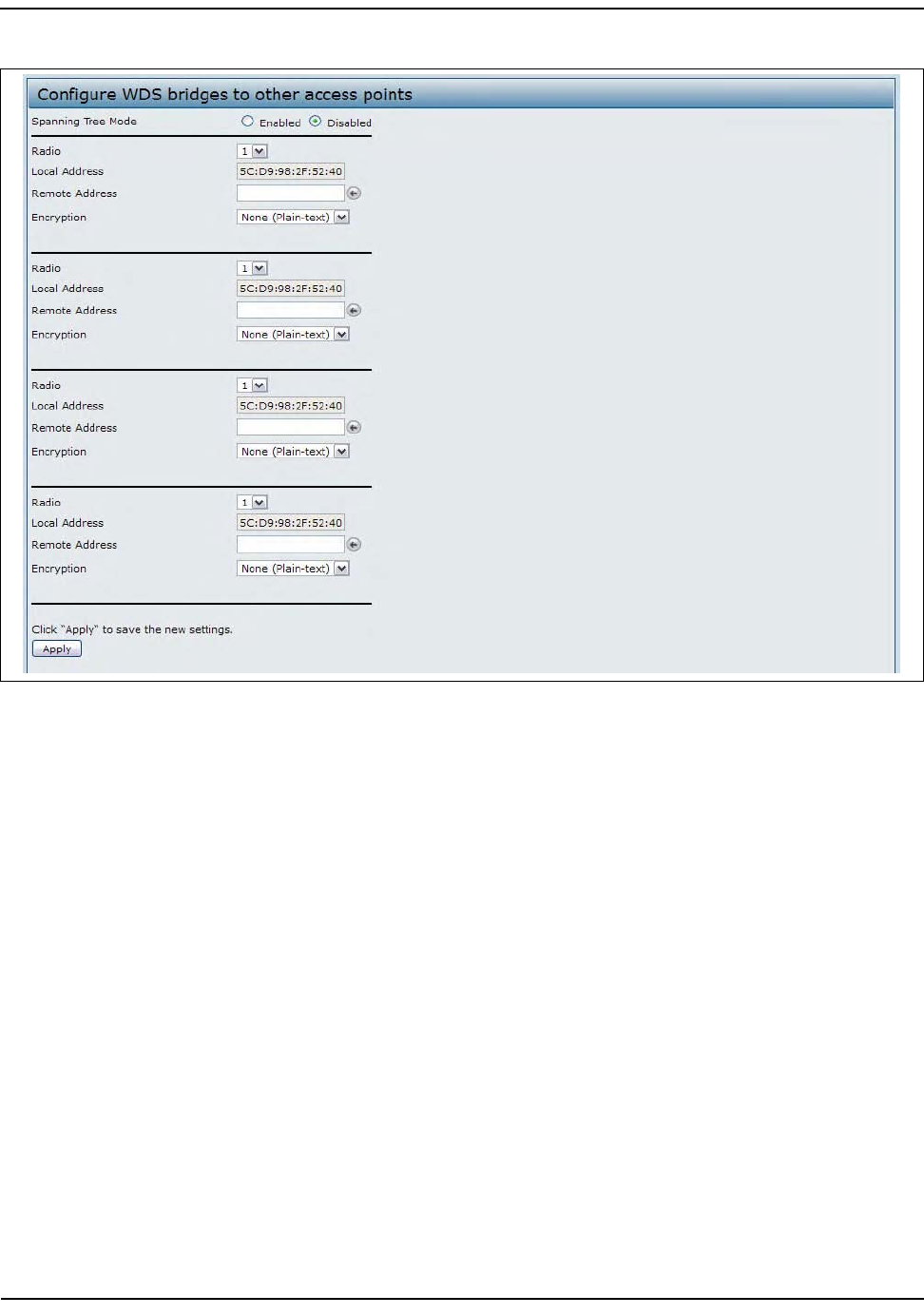
ConfiguringtheWirelessDistributionSystem(WDS)
D-Link UnifiedAccessPointAdministrator’sGuide
November2011 Page82
UnifiedAccessPointAdministrator’sGuide
Figure21:ConfiguringWDSSettings
BeforeyouconfigureWDSontheAP,notethefollowingguidelines:
•WhenusingWDS,besuretoconfigureWDSsettingsonbothAPsparticipatingintheWDSlink.
•YoucanhaveonlyoneWDSlinkbetweenanypairofAPs.Thatis,aremoteMACaddressmayappearonly
onceontheWDSpageforaparticularAP.
•BothAPsparticipatinginaWDSlinkmustbeonthesameRadiochannelandusingthesameIEEE802.11
mode.(See“ModifyingRadioSettings”onpage58forinformationonconfiguringtheRadiomodeand
channel.)
•When802.11hisoperational,settinguptwoWDSlinkscanbedifficult.See“Usingthe802.11hWireless
Mode”onpage57.
•IfyouuseWPAencryptionontheWDSlinkoverradio1,VAP0ofradio1mustuseWPAPersonalorWPA
Enterpriseasthesecuritymode.IfyouuseWPAonaWDSlinkoverradio2,VAP0ofradio2mustuseWPA
PersonalorWPAEnterpriseasthesecuritymode.

ConfiguringtheWirelessDistributionSystem(WDS)
D-Link UnifiedAccessPointAdministrator’sGuide
November2011 Page83
UnifiedAccessPointAdministrator’sGuide
ToconfigureWDSonthisAP,describeeachAPintendedtoreceivehand‐offsandsendinformationtothisAP.
ForeachdestinationAP,configurethefieldslistedinTable21.
IfyouselectNoneasyourpreferredWDSencryptionoption,youwillnotbeaskedtofillinanymorefieldson
theWDSpage.AlldatatransferredbetweenthetwoAPsontheWDSlinkwillbeunencrypted.
Table27:WDSSettings
Field Description
SpanningTree
Mode
SpanningTreeProtocol(STP)preventsswitchingloops.STPisrecommendedifyou
configureWDSlinks.
SelectEnabledtouseSTP
SelectDisabledtoturnoffSTPlinks(notrecommended)
Radio ForeachWDSlinkonatwo‐radioAP,selectRadioOneorRadioTwo.Therestofthe
settingsforthelinkapplytotheradioselectedinthisfield.Theread‐onlyLocalAddress
willchangedependingonwhichRadioyouselectinthisfield.
Note:ThisfieldisnotavailableontheDWL‐3600AP.
LocalAddress IndicatestheMACaddressesforthisAP.
ForeachWDSlinkonatwo‐radioAP,theLocalAddressreflectstheMACaddressforthe
internalinterfaceontheselectedradio(RadioOneonwlan0orRadioTwoonwlan1).
RemoteAddress SpecifytheMACaddressofthedestinationAP;thatis,theAPontheotherendofthe
WDSlinktowhichdatawillbesentorhanded‐offandfromwhichdatawillbereceived.
Clickthedrop‐downarrowtotherightoftheRemoteAddressfieldtoseealistofallthe
availableMACAddressesandtheirassociatedSSIDsonthenetwork.Selectthe
appropriateMACaddressfromthelist.
NOTE:TheSSIDdisplayedinthedrop‐downlistissimplytohelpyouidentifythecorrect
MACAddressforthedestinationAP.ThisSSIDisaseparateSSIDtothatwhichyousetfor
theWDSlink.Thetwodonot(andshouldnot)bethesamevalueorname.
Encryption Youcanusenoencryption,WEP,orWPA(PSK)ontheWDSlink.
IfyouareunconcernedaboutsecurityissuesontheWDSlinkyoumaydecidenottoset
anytypeofencryption.Alternatively,ifyouhavesecurityconcernsyoucanchoose
betweenStaticWEPandWPA(PSK).InWPA(PSK)mode,theAPusesWPA2‐PSKwith
CCMP(AES)encryptionovertheWDSlink.
NOTE:InordertoconfigureWPA‐PSKonanyWDSlink,VAP0oftheselectedradiomust
beconfiguredforWPA‐PSKorWPA‐Enterprise.
Note:TodisableaWDSlink,youmustremovethevalueconfiguredintheRemoteAddressfield.
ConfiguringtheWirelessDistributionSystem(WDS)
D-Link UnifiedAccessPointAdministrator’sGuide
November2011 Page84
UnifiedAccessPointAdministrator’sGuide
WEPonWDSLinks
Table28describestheadditionalfieldsthatappearwhenyouselectWEPastheencryptiontype.
WPA/PSKonWDSLinks
Table29describestheadditionalfieldsthatappearwhenyouselectWPA/PSKastheencryptiontype.
Table28:WEPonWDSLinks
Field Description
Encryption WEP
WEP SelectthisoptionifyouwanttosetWEPencryptionontheWDSlink.
KeyLength IfWEPisenabled,specifythelengthoftheWEPkey:
•64bits
• 128bits
KeyType IfWEPisenabled,specifytheWEPkeytype:
•ASCII
•Hex
Characters
Required
IndicatesthenumberofcharactersrequiredintheWEPkey.
ThenumberofcharactersrequiredupdatesautomaticallybasedonhowyousetKey
LengthandKeyType.
WEPKey Enterastringofcharacters.IfyouselectedASCII,enteranycombinationof0–9,a–z,and
A–Z.IfyouselectedHEX,enterhexadecimaldigits(anycombinationof0–9anda–for
A–F).ThesearetheRC4encryptionkeyssharedwiththestationsusingtheAP.
Note:ToconfigureWPA‐PSKonanyWDSlink,VAP0oftheselectedradiomustbeconfiguredforWPA‐
PSKorWPA‐Enterprise.
Table29:WPA/PSKonWDSLinks
Field Description
Encryption WPA(PSK)
SSID EnteranappropriatenameforthenewWDSlinkyouhavecreated.ThisSSIDshouldbe
differentfromtheotherSSIDsusedbythisAP.However,itisimportantthatthesame
SSIDisalsoenteredattheotherendoftheWDSlink.IfthisSSIDisnotthesameforboth
APsontheWDSlink,theywillnotbeabletocommunicateandexchangedata.
TheSSIDcanbeanyalphanumericcombination.
Key EnterauniquesharedkeyfortheWDSbridge.Thisuniquesharedkeymustalsobe
enteredfortheAPattheotherendoftheWDSlink.Ifthiskeyisnotthesameforboth
APs,theywillnotbeabletocommunicateandexchangedata.
TheWPA‐PSKkeyisastringofatleast8characterstoamaximumof63characters.
Acceptablecharactersincludeupperandlowercasealphabeticletters,thenumeric
digits,andspecialsymbolssuchas@and#.

ControllingAccessbyMACAuthentication
D-Link UnifiedAccessPointAdministrator’sGuide
November2011 Page85
UnifiedAccessPointAdministrator’sGuide
ControllingAccessbyMACAuthentication
AMediaAccessControl(MAC)addressisahardwareaddressthatuniquelyidentifieseachnodeofanetwork.
AllIEEE802networkdevicesshareacommon48‐bitMACaddressformat,usuallydisplayedasastringof12
hexadecimaldigitsseparatedbycolons,forexample
00:DC:BA:09:87:65
.Eachwirelessnetworkinterface
card(NIC)usedbyawirelessclienthasauniqueMACaddress.
YoucanusetheAdministratorUIontheAPoruseanexternalRADIUSservertocontrolaccesstothenetwork
throughtheAPbasedontheMACaddressofthewirelessclient.ThisfeatureiscalledMACAuthenticationor
MACFiltering.Tocontrolaccess,youconfigureagloballistofMACaddresseslocallyontheAPoronanexternal
RADIUSserver.Then,yousetafiltertospecifywhethertheclientswiththoseMACaddressesareallowedor
deniedaccesstothenetwork.WhenawirelessclientattemptstoassociatewithanAP,theAPlooksupthe
MACaddressoftheclientinthelocalStationsListorontheRADIUSserver.Ifitisfound,theglobalallowor
denysettingisapplied.Ifitisnotfound,theoppositeisapplied.
OntheVAPpage,theMACAuthenticationTypesettingcontrolswhethertheAPusesthestationlistconfigured
locallyontheMACAuthenticationpageortheexternalRADIUSserver.TheAllow/Blockfiltersettingonthe
MACAuthenticationpagedetermineswhethertheclientsinthestationlist(localorRADIUS)canaccessthe
networkthroughtheAP.FormoreinformationaboutsettingtheMACauthenticationtype,see“VirtualAccess
PointSettings”onpage70.
ConfiguringaMACFilterandStationListontheAP
TheMACAuthenticationpageallowsyoutocontrolaccesstoUAPbasedonMACaddresses.Basedonhow
yousetthefilter,youcanallowonlyclientstationswithalistedMACaddressordenyaccesstothestations
listed.
WhenyouenableMACAuthenticationandspecifyalistofapprovedMACaddresses,onlyclientswithalisted
MACaddresscanaccessthenetwork.IfyouspecifyMACaddressestodeny,allclientscanaccessthenetwork
exceptfortheclientsonthedenylist.
ToenablefilteringbyMACaddress,clicktheMACAuthenticationtab.
Note:AfteryouconfiguretheWDSsettings,youmustclickApplytoapplythechangesandtosavethe
settings.ChangingsomesettingsmightcausetheAPtostopandrestartsystemprocesses.Ifthis
happens,wirelessclientswilltemporarilyloseconnectivity.WerecommendthatyouchangeAP
settingswhenWLANtrafficislow.
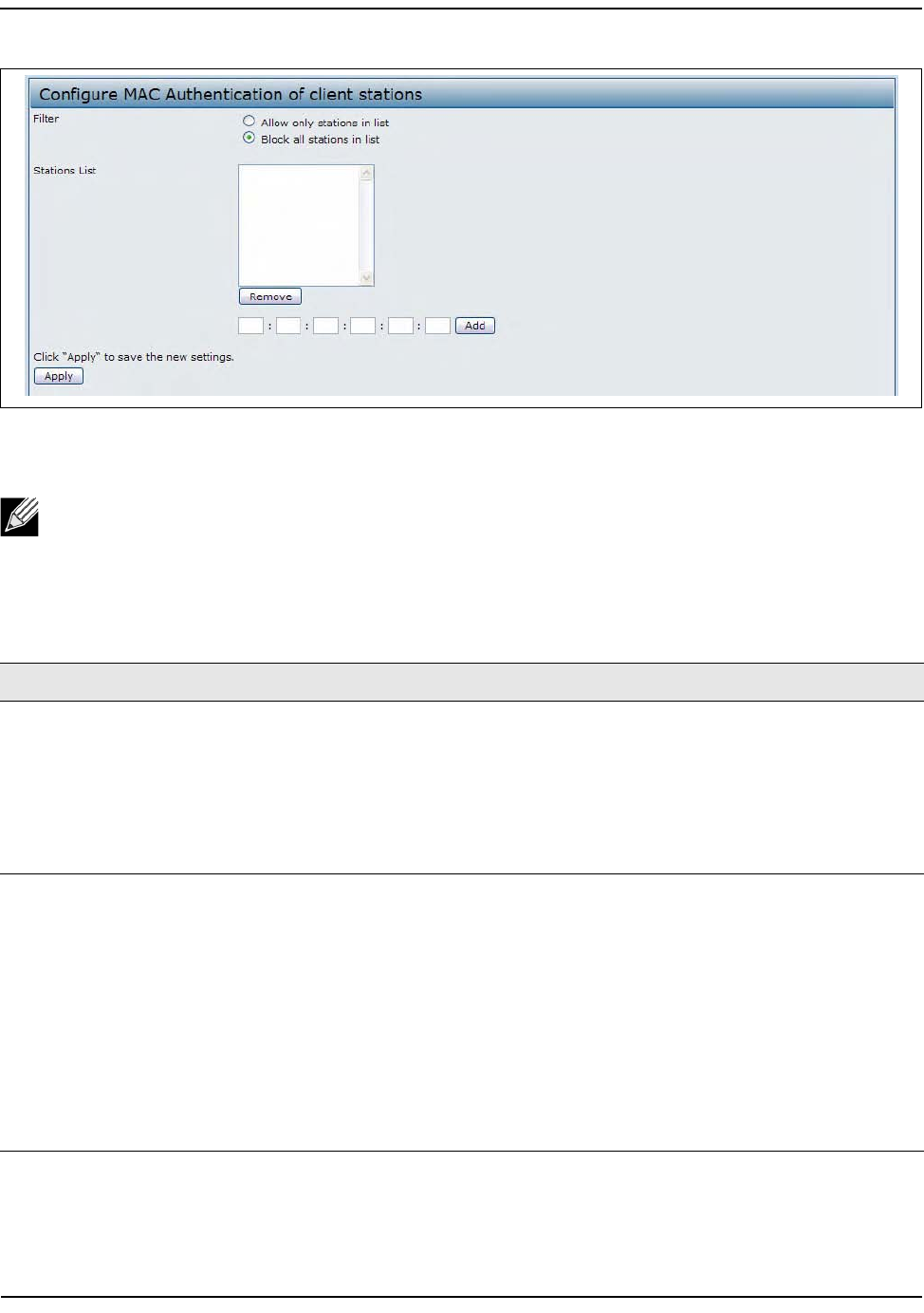
ControllingAccessbyMACAuthentication
D-Link UnifiedAccessPointAdministrator’sGuide
November2011 Page86
UnifiedAccessPointAdministrator’sGuide
Figure22:ConfiguringMACAuthentication
Table30describesthefieldsandconfigurationoptionsavailableontheMACAuthenticationpage
Note:GlobalMACAuthenticationsettingsapplytoallVAPsonallsupportedradios.
Table30:MACAuthentication
Field Description
Filter TosettheMACAddressFilter,selectoneofthefollowingoptions:
•Allowonlystationsinthelist.AnystationthatisnotintheStationsListisdenied
accesstothenetworkthroughtheAP.
•Blockallstationsinlist.Onlythestationsthatappearinthelistaredeniedaccessto
thenetworkthroughtheAP.Allotherstationsarepermittedaccess.
Note:Thefilteryouselectisappliedtotheclientsinthestationlist,regardlessof
whetherthatstationlistislocalorontheRADIUSserver.
StationsList Thisisthelocallistofclientsthatareeitherpermittedordeniedaccesstothenetwork
throughtheAP.ToaddaMACAddresstothelocalStationsList,enterits48‐bitMAC
addressintothelowertextboxes,thenclickAdd.
ToremoveaMACAddressfromtheStationsList,selectits48‐bitMACaddress,thenclick
Remove.
Thestationsinthelistwilleitherbeallowedordeniedaccessbasedonhowyousetthe
filterinthepreviousfield.
Note:IftheMACauthenticationtypefortheVAPissettoLocal,theAPusestheStations
Listtopermitordenytheclientsaccesstothenetwork.IftheMACauthenticationtype
issettoRADIUS,theAPignorestheMACaddressesconfiguredinthislistandusesthe
listthatisstoredontheRADIUSserver.TheMACauthenticationtypeissetontheVAP
configurationpage.

ControllingAccessbyMACAuthentication
D-Link UnifiedAccessPointAdministrator’sGuide
November2011 Page87
UnifiedAccessPointAdministrator’sGuide
ConfiguringMACAuthenticationontheRADIUSServer
IfyouuseRADIUSMACauthenticationforMAC‐basedaccesscontrol,youmustconfigureastationlistonthe
RADIUSserver.ThestationlistcontainsclientMACaddressentries,andtheformatforthelistisdescribedin
thefollowingtable.
Note:AfteryouconfigurelocalMACAuthenticationsettings,youmustclickApplytoapplythe
changesandtosavethesettings.ChangingsomesettingsmightcausetheAPtostopandrestart
systemprocesses.Ifthishappens,wirelessclientswilltemporarilyloseconnectivity.Werecommend
thatyouchangeAPsettingswhenWLANtrafficislow.
Table31:RADIUSServerAttributesforMACAuthentication
RADIUSServerAttribute Description Value
User‐Name(1) MACaddressoftheclientstation. ValidEthernetMAC
Address.
User‐Password(2) AfixedglobalpasswordusedtolookupaclientMAC
entry.
NOPASSWORD
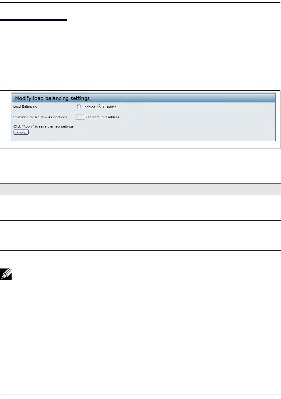
ConfiguringLoadBalancing
D-Link UnifiedAccessPointAdministrator’sGuide
November2011 Page88
UnifiedAccessPointAdministrator’sGuide
ConfiguringLoadBalancing
YoucansetnetworkutilizationthresholdsontheUAPtomaintainthespeedandperformanceofthewireless
networkasclientsassociateanddisassociatewiththeAP.Theloadbalancingsettingsapplytoallsupported
radios.
Toconfigureloadbalancingandsetlimitsandbehaviortobetriggeredbyaspecifiedutilizationrateofthe
accesspoint,clicktheLoadBalancingtabandupdatethefieldsshowninthefollowingfigure.
Figure23:ConfiguringLoadBalancing
Table32:LoadBalancing
Field Description
LoadBalancing Enableordisableloadbalancing:
ToenableloadbalancingonthisAP,clickEnable.
TodisableloadbalancingonthisAP,clickDisable.
UtilizationforNo
NewAssociations
Providethepercentageofnetworkbandwidthutilizationallowedontheradiobeforethe
APstopsacceptingnewclientassociations.
Thedefaultis0,whichmeansthatallnewassociationswillbeallowedregardlessofthe
utilizationrate.
Note:Afteryouconfiguretheloadbalancingsettings,youmustclickApplytoapplythechangesand
tosavethesettings.ChangingsomesettingsmightcausetheAPtostopandrestartsystemprocesses.
Ifthishappens,wirelessclientswilltemporarilyloseconnectivity.WerecommendthatyouchangeAP
settingswhenWLANtrafficislow.

ManagedAccessPointOverview
D-Link UnifiedAccessPointAdministrator’sGuide
November2011 Page89
UnifiedAccessPointAdministrator’sGuide
ManagedAccessPointOverview
TheUAPcanoperateintwomodes:StandaloneModeorManagedMode.InStandaloneMode,theUAPacts
asanindividualAPinthenetwork,andyoumanageitbyusingtheAdministratorWebUserInterface(UI),CLI,
orSNMP.InManagedMode,theUAPispartoftheD‐LinkUnifiedWiredandWirelessSystem,andyoumanage
itbyusingtheD‐LinkUnifiedWirelessSwitch.IfanAPisinManagedMode,theAdministratorWebUI,Telnet,
SSH,andSNMPservicesaredisabled.
OntheUAP,youcanconfiguretheIPaddressesofuptofourD‐LinkUnifiedWirelessSwitchesthatcanmanage
it.InordertomanagetheAP,theswitchandAPmustdiscovereachother.Therearemultiplewaysforaswitch
todiscoveranAP.AddingtheIPaddressoftheswitchtotheAPwhileitisinStandaloneModeisonewayto
enableswitch‐to‐APdiscovery.
TransitioningBetweenModes
Every30seconds,theD‐LinkUnifiedWirelessSwitchsendsakeepalivemessagetoalloftheaccesspointsit
manages.EachAPchecksforthekeepalivemessagesontheSSLTCPconnection.AslongastheAPmaintains
communicationwiththeswitchthroughthekeepalivemessages,itremainsinManagedMode.
IftheAPdoesnotreceiveamessagewithin45secondsofthelastkeepalivemessage,theAPassumesthe
switchhasfailedandterminatesitsTCPconnectiontotheswitch,andtheAPentersStandaloneMode.
OncetheAPtransitionstoStandaloneMode,itcontinuestoforwardtrafficwithoutanyloss.TheAPusesthe
configurationontheVAPsconfiguredinVLANForwardingmode(thestandard,non‐tunneledmode).
WhiletheAPisinStandaloneMode,youcanmanageitbyusingtheWebinterfaceortheCLI(throughTelnet
orSSH).
ForanyclientsthatareconnectedtotheAPthroughtunneledVAPs,theAPsendsdisassociatemessagesand
disablesthetunneledVAPs.
AslongastheManagedAPAdministrativeModeissettoEnabled,asFigure24onpage90shows,theAPstarts
discoveryprocedures.IftheAPestablishesaconnectionwithawirelessswitch,whichmayormaynotbethe
sameswitchitwasconnectedtobefore,theswitchsendstheAPitsconfigurationandtheAPsendsthewireless
switchinformationaboutallcurrentlyassociatedclients.
Aftertheconfigurationfromtheswitchisapplied,theAPradio(s)restart.Clienttrafficisbrieflyinterrupted
untiltheradio(s)areupandtheclientsarere‐associated.
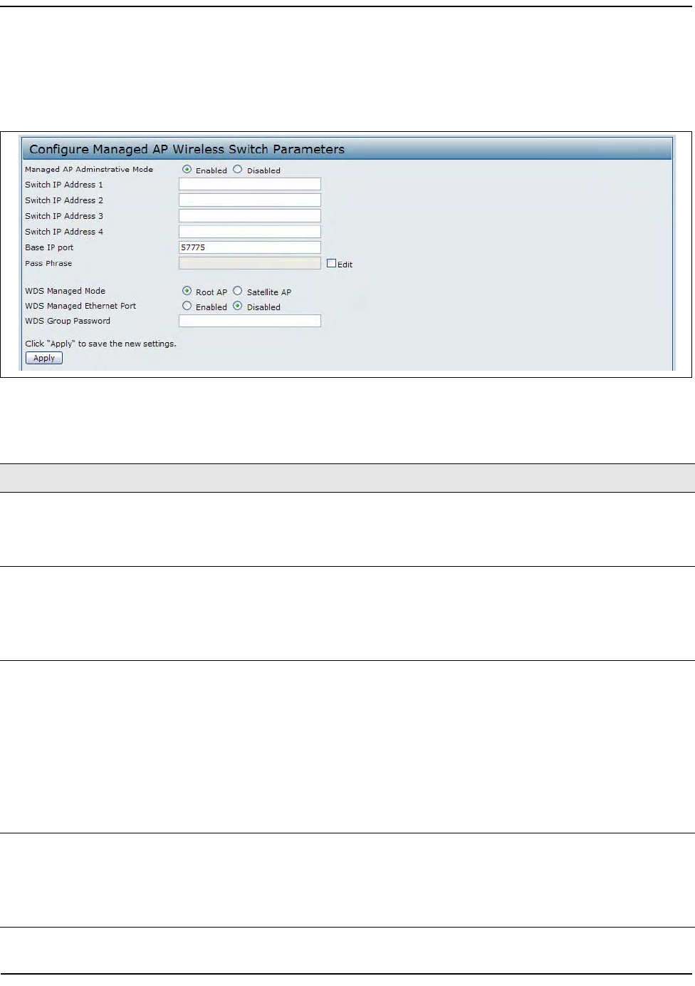
ManagedAccessPointOverview
D-Link UnifiedAccessPointAdministrator’sGuide
November2011 Page90
UnifiedAccessPointAdministrator’sGuide
ConfiguringManagedAccessPointSettings
ToaddtheIPaddressofaD‐LinkUnifiedWirelessSwitchtotheAP,clicktheManagedAccessPointtabunder
theManageheadingandupdatethefieldsshowninTable33.
Figure24:ConfiguringManagedAccessPointSettings
Table33:ManagedAccessPoint
Field Description
ManagedAP
AdministrativeMode
ClickEnabledtoallowtheAPandswitchtodiscovereachother.IftheAPsuccessfully
authenticatesitselfwithawirelessswitch,youwillnotbeabletoaccessthe
AdministratorUI.
ClickDisabledtopreventtheAPfromcontactingwirelessswitches.
SwitchIPaddress EntertheIPaddressofuptofourwirelessswitchesthatcanmanagetheAP.Youcan
entertheIPaddressindottedformatorasanDNSname.
Youcanviewalistofwirelessswitchesonyournetworkthatwereconfiguredbyusing
aDHCPserver.
TheAPattemptstocontactSwitchIPAddress1first.
BaseIPPort ThestartingIPportnumberusedbythewirelessfeature(inarangeof10consecutive
portnumbers).Onlythefirstnumberintherangeisconfigurable.Thedefaultvalueis
57775(through57784).
Note:WhenthewirelessBaseIPPortnumberischangedontheswitch,thewireless
featureisautomaticallydisabledandre‐enabled.Thenewvalueisnotsentaspartof
theglobalswitchconfigurationintheclusterconfigurationdistributioncommand;
everyswitchintheclustermustbeconfiguredindependentlywiththenewWirelessIP
portnumber.
Note:WhentheWirelessBaseIPPortnumberischangedfromitsdefaultvalueonthe
switch,itmustalsobechangedontheAccessPoints.
PassPhrase SelecttheEditoptionandenterapassphrasetoallowtheAPtoauthenticateitselfwith
thewirelessswitch.Thepassphrasemustbebetween8and63characters.
Toremovethepassword,selectEdit,deletetheexistingpassword,andthenclick
Apply.
Youmustconfigurethesamepassphraseontheswitch.

ManagedAccessPointOverview
D-Link UnifiedAccessPointAdministrator’sGuide
November2011 Page91
UnifiedAccessPointAdministrator’sGuide
IftheUAPsuccessfullyauthenticateswithaD‐LinkUnifiedWirelessSwitch,youwilllooseaccesstotheAP
throughtheAdministratorUI.
WDSManagedMode SpecifywhethertheAPwillactasaRootAPorSatelliteAPwithintheWDSgroup:
•RootAP—Actsasabridgeorrepeateronthewirelessmediumandcommunicates
withtheswitchviathewiredlink.
• SatelliteAP—CommunicateswiththeswitchviaaWDSlinktotheRootAP.This
modeenablestheSatelliteAPtodiscoverandestablishWDSlinkwiththeRootAP.
WDSManaged
EthernetPort
SpecifywhethertheEthernetportistobeenabledordisabledwhentheAPbecomes
partofaWDSgroup.
WDSGroupPassword PasswordforWPA2PersonalauthenticationusedtoestablishtheWDSlinks.Onlythe
SatelliteAPsneedthisconfiguration.TheRootAPsgetthepasswordfromtheswitch
whentheybecomemanaged.
Note:AfteryouconfigurethesettingsontheManagedAccessPointpage,youmustclickApplyto
applythechangesandtosavethesettings.ChangingsomesettingsmightcausetheAPtostopand
restartsystemprocesses.Ifthishappens,wirelessclientswilltemporarilyloseconnectivity.We
recommendthatyouchangeAPsettingswhenWLANtrafficislow.
Table33:ManagedAccessPoint
Field Description
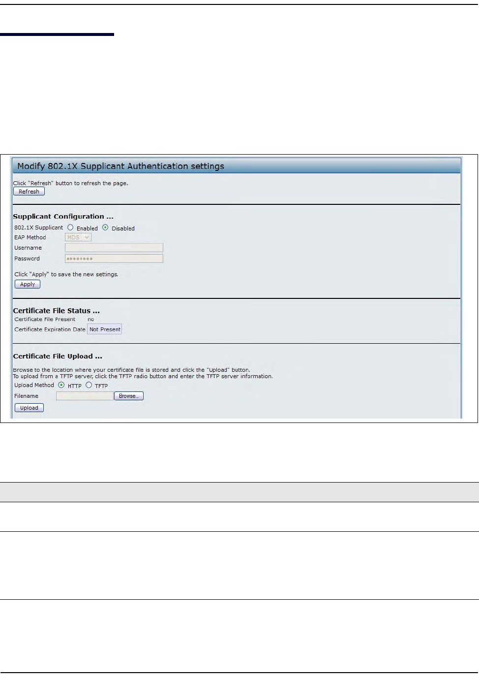
Configuring802.1XAuthentication
D-Link UnifiedAccessPointAdministrator’sGuide
November2011 Page92
UnifiedAccessPointAdministrator’sGuide
Configuring802.1XAuthentication
OnnetworksthatuseIEEE802.1X,port‐basednetworkaccesscontrol,asupplicant(client)cannotgainaccess
tothenetworkuntilthe802.1Xauthenticatorgrantsaccess.Ifyournetworkuses802.1X,youmustconfigure
802.1XauthenticationinformationthattheAPcansupplytotheauthenticator.
ToconfiguretheUAP802.1XsupplicantusernameandpasswordbyusingtheWebinterface,clickthe
AuthenticationtabandconfigurethefieldsshowninTable34.
Figure25:IEEE802.1XAuthentication
Table34:IEEE802.1XSupplicantAuthentication
FieldDescription
802.1XSupplicant ClickEnabledtoenabletheAdministrativestatusofthe802.1XSupplicant.
ClickDisabledtodisabletheAdministrativestatusofthe802.1XSupplicant.
EAPMethod SelectoneofthefollowingEAPmethodstouseforcommunicationbetweentheAPand
theauthenticator:
•MD5
•PEAP
•TLS
Configuring802.1XAuthentication
D-Link UnifiedAccessPointAdministrator’sGuide
November2011 Page93
UnifiedAccessPointAdministrator’sGuide
Username EntertheusernamefortheAPtousewhenrespondingtorequestsfroman802.1X
authenticator.
Theusernamecanbe1to64charactersinlength.ASCIIprintablecharactersareallowed,
whichincludesupperandlowercasealphabeticletters,thenumericdigits,andspecial
symbolssuchas@and#.
Password EnterthepasswordfortheAPtousewhenrespondingtorequestsfroman802.1X
authenticator.
Thepasswordcanbe1to64charactersinlength.ASCIIprintablecharactersareallowed,
whichincludesupperandlowercaseletters,numbers,andspecialsymbolssuchas@
and#.
CertificateFile
Status
Indicateswhetheracertificatefileispresentandwhenthatcertificateexpires.
CertificateFile
Upload
UploadacertificatefiletotheAPbyusingHTTPorTFTP:
•HTTP—BrowsetothelocationwherethecertificatefileisstoredandclickUpload.
•TFTP—SpecifytheIPaddressoftheTFTPserverwherethecertificatefileislocated
andprovidethefilename,includingthefilepath,thenclickUpload.
Note:AfteryouconfigurethesettingsontheAuthenticationpage,youmustclickApplytoapplythe
changesandtosavethesettings.ChangingsomesettingsmightcausetheAPtostopandrestart
systemprocesses.Ifthishappens,wirelessclientswilltemporarilyloseconnectivity.Werecommend
thatyouchangeAPsettingswhenWLANtrafficislow.
Table34:IEEE802.1XSupplicantAuthentication(Cont.)
FieldDescription
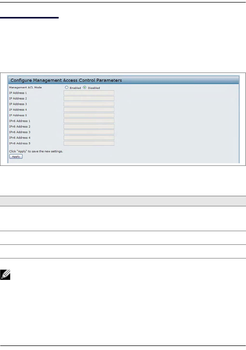
CreatingaManagementAccessControlList
D-Link UnifiedAccessPointAdministrator’sGuide
November2011 Page94
UnifiedAccessPointAdministrator’sGuide
CreatingaManagementAccessControlList
Youcancreateanaccesscontrollist(ACL)thatlistsuptofiveIPv4hostsandfiveIPv6hoststhatareauthorized
toaccesstheAPmanagementinterface.Ifthisfeatureisdisabled,anyonecanaccessthemanagement
interfacefromanynetworkclientbysupplyingthecorrectAPusernameandpassword.
Tocreateanaccesslist,clicktheManagementACLtab.
Figure26:ManagementACL
Table35:ManagementACL
Field Description
ManagementACLMode EnableordisablethemanagementACLfeature.AtleastoneIPv4orIPv6address
shouldbeconfiguredbeforeenablingManagementACLMode.Ifenabled,only
theIPaddressesyouspecifywillhaveWeb,Telnet,SSH,andSNMPaccesstothe
managementinterface.
IPAddress(1–5) EnteruptofiveIPv4addressesthatareallowedmanagementaccesstotheAP.Use
dotted‐decimalformat(forexample,192.168.10.10).
IPv6Address(1–5) EnteruptofiveIPv6addressesthatareallowedmanagementaccesstotheAP.Use
thestandardIPv6addressformat(forexample2001:0db8:1234::abcd).
Note:Afteryouconfigurethesettings,clickApplytoapplythechangesandtosavethesettings.

ConfiguringAccessPointServices
D-Link UnifiedAccessPointAdministrator’sGuide
November2011 Page95
UnifiedAccessPointAdministrator’sGuide
Section5:ConfiguringAccessPointServices
ThissectiondescribeshowtoconfigureservicesontheUAPandcontainsthefollowingsubsections:
•“ConfiguringSNMPontheAccessPoint”
•“WebServerSettings”
•“SettingtheSSHStatus”
•“SettingtheTelnetStatus”
•“ConfiguringQualityofService”
•“ConfiguringEmailAlert”
•“EnablingtheTimeSettings(NTP)”
ConfiguringSNMPontheAccessPoint
SimpleNetworkManagementProtocol(SNMP)definesastandardforrecording,storing,andsharing
informationaboutnetworkdevices.SNMPfacilitatesnetworkmanagement,troubleshooting,and
maintenance.TheAPsupportsSNMPversions1,2,and3.Unlessspecificallynoted,allconfiguration
parametersonthispageapplytoSNMPv1andSNMPv2conly.
KeycomponentsofanySNMP‐managednetworkaremanageddevices,SNMPagents,andamanagement
system.TheagentsstoredataabouttheirdevicesinManagementInformationBases(MIBs)andreturnthis
datatotheSNMPmanagerwhenrequested.ManageddevicescanbenetworknodessuchasAPs,routers,
switches,bridges,hubs,servers,orprinters.
TheUAPcanfunctionasanSNMPmanageddeviceforseamlessintegrationintonetworkmanagementsystems
suchasHPOpenView.
FromtheSNMPpageundertheServicesheading,youcanstartorstopcontrolofSNMPagents,configure
communitypasswords,accessMIBs,andconfigureSNMPTrapdestinations.
FromthepagesundertheSNMPv3heading,youcanmanageSNMPv3usersandtheirsecuritylevelsanddefine
accesscontroltotheSNMPMIBs.ForinformationabouthowtoconfigureSNMPv3views,groups,users,and
targets,see“ConfiguringSNMPv3”onpage111.
ToconfigureSNMP,clicktheSNMPtabundertheServicesheadingandupdatethefieldsdescribedinTable36
onpage96
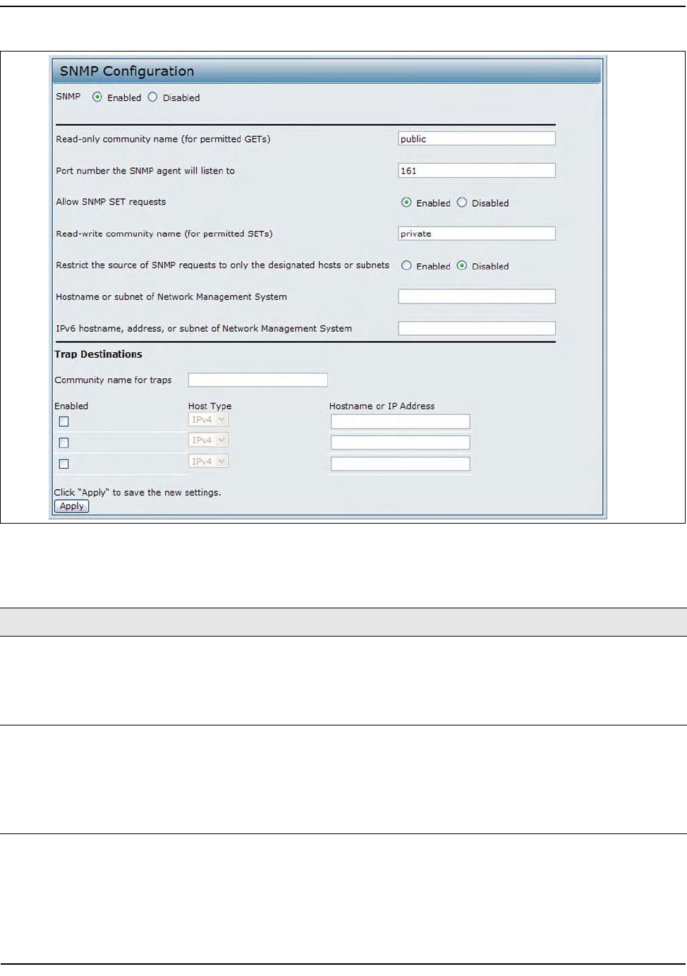
ConfiguringSNMPontheAccessPoint
D-Link UnifiedAccessPointAdministrator’sGuide
November2011 Page96
UnifiedAccessPointAdministrator’sGuide
Figure27:ModifyingSNMPSettings
Table36:SNMPSettings
Field Description
SNMP
Enabled/Disabled
YoucanspecifytheSNMPadministrativemodeonyournetwork.BydefaultSNMP
isenabled.ToenableSNMP,clickEnabled.TodisableSNMP,clickDisabled
.
A
fter
changingthemode,y
oumustclickApplytosaveyourconfigurationchanges.
Note: IfSNMPisdisabled,allremainingfieldsontheSNMPpagearedisabled.This
isaglobalSNMPparameterwhichappliestoSNMPv1,SNMPv2c,andSNMPv3.
Read‐only
communityname
(forpermittedSNMPget
operations)
Enteraread‐onlycommunityname.Thevalidrangeis1‐256characters.
Thecommunityname,asdefinedinSNMPv2c,actsasasimpleauthentication
mechanismtorestrictthemachinesonthenetworkthatcanrequestdatatothe
SNMPagent.Thenamefunctionsasapassword,andtherequestisassumedtobe
authenticifthesenderknowsthepassword.
Thecommunitynamecanbeinanyalphanumericformat.

ConfiguringSNMPontheAccessPoint
D-Link UnifiedAccessPointAdministrator’sGuide
November2011 Page97
UnifiedAccessPointAdministrator’sGuide
PortnumbertheSNMP
agentwill
listento
BydefaultanSNMPagentonlylistenstorequestsfromport161.However,youcan
configurethissotheagentlistenstorequestsonanotherport.
EntertheportnumberonwhichyouwanttheSNMPagentstolistentorequests.
Thevalidrangeis1‐65535.
Note:ThisisaglobalSNMPparameterthatappliestoSNMPv1,SNMPv2c,and
SNMPv3.
AllowSNMPsetrequests YoucanchoosewhetherornottoallowSNMPsetrequestsontheAP.Enabling
SNMPsetrequestsmeansthatmachinesonthenetworkcanexecuteconfiguration
changesviatheSNMPagentontheAPtotheD‐LinkSystemMIB.ToenableSNMP
setrequests,clickEnabled.TodisableSNMPsetrequests,clickDisabled.
Read‐writecommunity
name(forpermitted
SNMPsetoperations)
IfyouhaveenabledSNMPsetrequestsyoucansetaread‐writecommunityname.
Thevalidrangeis1‐256characters.
Settingacommunitynameissimilartosettingapassword.Onlyrequestsfromthe
machinesthatidentifythemselveswiththiscommunitynamewillbeaccepted.
Thecommunitynamecanbeinanyalphanumericformat.
Restrictthesourceof
SNMPrequeststoonly
thedesignatedhostsor
subnets
YoucanrestrictthesourceofpermittedSNMPrequests.
TorestrictthesourceofpermittedSNMPrequests,clickEnabled.
TopermitanysourcesubmittinganSNMPrequest,clickDisabled.
Hostname,addressor
subnetofNetwork
ManagementSystem
SpecifytheIPv4DNShostnameorsubnetofthemachinesthatcanexecutegetand
setrequeststothemanageddevices.Thevalidrangeis1‐256characters.
Aswithcommunitynames,thisprovidesalevelofsecurityonSNMPsettings.The
SNMPagentwillonlyacceptrequestsfromthehostnameorsubnetspecifiedhere.
Tospecifyasubnet,enteroneormoresubnetworkaddressrangesintheform
address/mask_lengthwhereaddressisanIPaddressandmask_lengthisthe
numberofmaskbits.Bothformatsaddress/maskandaddress/
mask_lengtharesupported.Individualhostscanbeprovidedforthis,i.e.I.P
AddressorHostname.Forexample,ifyouenterarangeof
192.168.1.0/24
this
specifiesasubnetworkwithaddress
192.168.1.0
andasubnetmaskof
255.255.255.0
.
TheaddressrangeisusedtospecifythesubnetofthedesignatedNMS.Only
machineswithIPaddressesinthisrangearepermittedtoexecutegetandset
requestsonthemanageddevice.Giventheexampleabove,themachineswith
addressesfrom
192.168.1.1
through
192.168.1.254
canexecuteSNMP
commandsonthedevice.(Theaddressidentifiedbysuffix.0inasubnetworkrange
isalwaysreservedforthesubnetaddress,andtheaddressidentifiedby.255inthe
rangeisalwaysreservedforthebroadcastaddress).
Asanotherexample,ifyouenterarangeof
10.10.1.128/25
machineswithIP
addressesfrom
10.10.1.129
through
10.10.1.254
canexecuteSNMP
requestsonmanageddevices.Inthisexample,
10.10.1.128
isthenetwork
addressand
10.10.1.255
isthebroadcastaddress.126addresseswouldbe
designated.
IPv6HostnameorIPv6
subnetofNetwork
ManagementSystem
SpecifytheIPv6DNShostnameorsubnetofthemachinesthatcanexecutegetand
setrequeststothemanageddevices.
Table36:SNMPSettings(Cont.)
Field Description

ConfiguringSNMPontheAccessPoint
D-Link UnifiedAccessPointAdministrator’sGuide
November2011 Page98
UnifiedAccessPointAdministrator’sGuide
Communitynamefor
traps
EntertheglobalcommunitystringassociatedwithSNMPtraps.Thevalidrangeis
1‐256characters.
Trapssentfromthedevicewillprovidethisstringasacommunityname.
Thecommunitynamecanbeinanyalphanumericformat.Specialcharactersare
notpermitted.
HostnameorIPaddress EntertheDNShostnameofthecomputertowhichyouwanttosendSNMPtraps.
Thevalidrangeis1‐256characters.
AnexampleofaDNShostnameis:snmptraps.foo.com.
SinceSNMPtrapsaresent
randomlyfromtheSNMPagent,itmakessensetospecifywhereexactlythetraps
shouldbesent.YoucanadduptoamaximumofthreeDNShostnames.Ensureyou
selecttheEnabledcheckboxbesidetheappropriatehostname.
Note:AfteryouconfiguretheSNMPsettings,youmustclickApplytoapplythechangesandtosave
thesettings.ChangingsomesettingsmightcausetheAPtostopandrestartsystemprocesses.Ifthis
happens,wirelessclientswilltemporarilyloseconnectivity.WerecommendthatyouchangeAP
settingswhenWLANtrafficislow.
Table36:SNMPSettings(Cont.)
Field Description
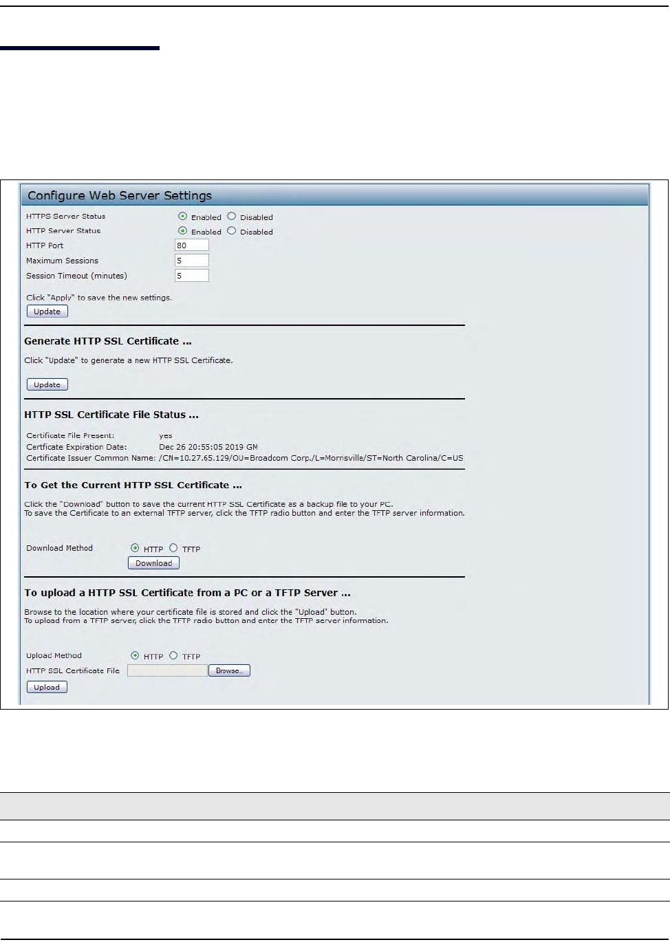
WebServerSettings
D-Link UnifiedAccessPointAdministrator’sGuide
November2011 Page99
UnifiedAccessPointAdministrator’sGuide
WebServerSettings
TheAPcanbemanagedthroughHTTPorsecureHTTP(HTTPS)sessions.BydefaultbothHTTPandHTTPS
accessareenabled.Eitheraccesstypecanbedisabledseparately.
ToconfigureWebserversettings,clickWebServertab.
Figure28:ConfiguringWebServerSettings
Table37:WebServerSettings
Field Description
HTTPSServerStatus EnableordisableaccessthroughaSecureHTTPServer(HTTPS).
HTTPServerStatus EnableordisableaccessthroughHTTP.ThissettingisindependentoftheHTTPSserver
statussetting.
HTTPPort SpecifytheportnumberforHTTPtraffic(defaultis80).
WebServerSettings
D-Link UnifiedAccessPointAdministrator’sGuide
November2011 Page100
UnifiedAccessPointAdministrator’sGuide
MaximumSessions WhenauserlogsontotheAPwebinterface,asessioniscreated.Thissessionis
maintaineduntiltheuserlogsofforthesessioninactivitytimerexpires.
Enterthenumberwebsessions,includingbothHTTPandHTTPs,thatcanexistatthe
sametime.Therangeis1–10sessions.Ifthemaximumnumberofsessionsisreached,
thenextuserwhoattemptstologontotheAPwebinterfacereceivesanerrormessage
aboutthesessionlimit.
SessionTimeout Enterthemaximumamountoftime,inminutes,aninactiveuserremainsloggedonto
theAPwebinterface.Whentheconfiguredtimeoutisreached,theuserisautomatically
loggedofftheAP.Therangeis1–1440minutes(1440minutes=1day).
GenerateSSL
Certificate
SelectthisoptiontogenerateanewSSLcertificateforthesecureWebserver.Thisshould
bedoneoncetheaccesspointhasanIPaddresstoensurethatthecommonnamefor
thecertificatematchestheIPaddressoftheUAP.GeneratinganewSSLcertificatewill
restartthesecureWebserver.Thesecureconnectionwillnotworkuntilthenew
certificateisacceptedonthebrowser.
HTTPSSLCertificate
FileStatus
Indicateswhetheracertificatefileispresentandspecifiesitsexpirationdateandissuer
commonname.
ToGettheCurrent
HTTPSSLCertificate
SaveacopyofthecurrentHTTPSSLcertificateonalocalsystemorTFTPserver.
•HTTP—ClickDownloadandspecifywheretostorethebackupcopyofthecertificate
file.
•TFTP—Provideafilenameforthecertificatefile,includingthefilepath,specifythe
IPaddressoftheTFTPserverwherethecertificatefilecopyistobestored,andthen
clickDownload.
TouploadaHTTP
SSLCertificatefrom
aPCoraTFTP
Server
UploadacertificatefiletotheAPbyusingHTTPorTFTP:
•HTTP—BrowsetothelocationwherethecertificatefileisstoredandclickUpload.
•TFTP—SpecifytheIPaddressoftheTFTPserverwherethecertificatefileislocated
andprovidethefilename,includingthefilepath,thenclickUpload.
Note:ClickApplytoapplythechangesandtosavethesettings.Ifyoudisabletheprotocolyouare
currentlyusingtoaccesstheAPmanagementinterface,thecurrentconnectionwillendandyouwill
notbeabletoaccesstheAPbyusingthatprotocoluntilitisenabled.
Table37:WebServerSettings(Cont.)
Field Description
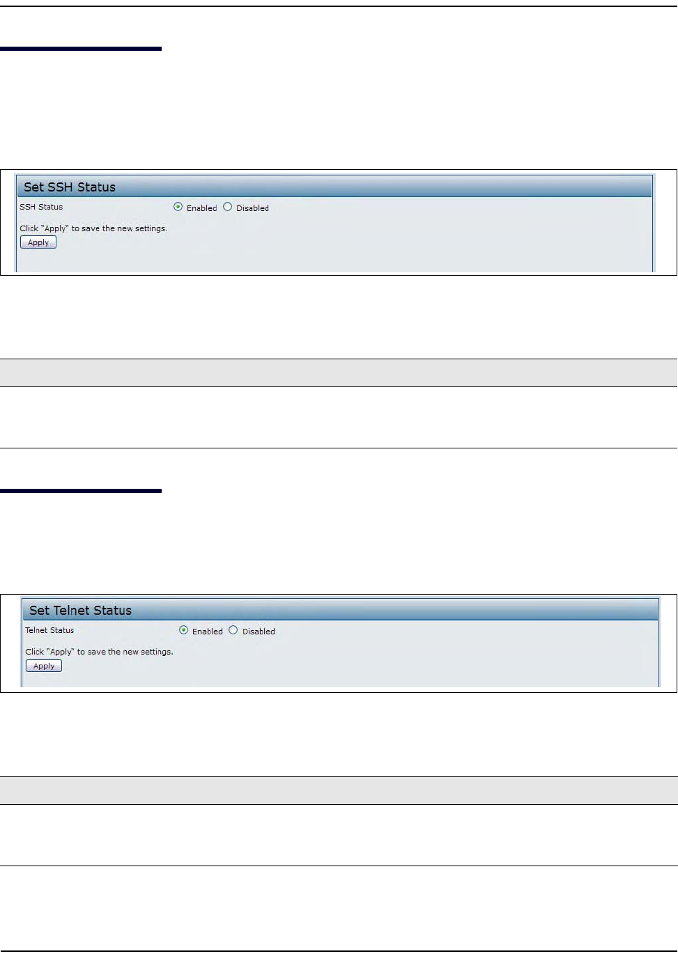
SettingtheSSHStatus
D-Link UnifiedAccessPointAdministrator’sGuide
November2011 Page101
UnifiedAccessPointAdministrator’sGuide
SettingtheSSHStatus
SecureShell(SSH)isaprogramthatprovidesaccesstotheDWL‐x600APCLIfromaremotehost.SSHismore
securethanTelnetforremoteaccessbecauseitprovidesstrongauthenticationandsecurecommunications
overinsecurechannels.FromtheSSHpage,youcanenableordisableSSHaccesstothesystem.
Figure29:SSHStatus
SettingtheTelnetStatus
TelnetisaprogramthatprovidesaccesstotheDWL‐x600APCLIfromaremotehost.FromtheTelnetpage,you
canenableordisableTelnetaccesstothesystem.
Figure30:TelnetStatus
Table38:SSHSettings
Field Description
SSHStatus ChoosetoeitherenableordisableSSHaccesstotheAPCLI:
•TopermitremoteaccesstotheAPbyusingSSH,clickEnabled.
•TopreventremoteaccesstotheAPbyusingSSH,clickDisabled.
Table39:TelnetSettings
Field Description
TelnetStatus ChoosetoeitherenableordisableTelnet accesstotheAPCLI:
•TopermitremoteaccesstotheAPbyusingTelnet,clickEnabled.
•TopreventremoteaccesstotheAPbyusingTelnet,clickDisabled.

ConfiguringQualityofService
D-Link UnifiedAccessPointAdministrator’sGuide
November2011 Page102
UnifiedAccessPointAdministrator’sGuide
ConfiguringQualityofService
QualityofService(QoS)providesyouwiththeabilitytospecifyparametersonmultiplequeuesforincreased
throughputandbetterperformanceofdifferentiatedwirelesstrafficlikeVoice‐over‐IP(VoIP),othertypesof
audio,video,andstreamingmedia,aswellastraditionalIPdataovertheUAP.
ConfiguringQoSontheUAPconsistsofsettingparametersonexistingqueuesfordifferenttypesofwireless
traffic,andeffectivelyspecifyingminimumandmaximumwaittimes(throughContentionWindows)for
transmission.ThesettingsdescribedhereapplytodatatransmissionbehaviorontheAPonly,nottothatof
theclientstations.
APEnhancedDistributedChannelAccess(EDCA)ParametersaffecttrafficflowingfromtheAPtotheclient
station.
StationEnhancedDistributedChannelAccess(EDCA)Parametersaffecttrafficflowingfromtheclientstationto
theAP.
ThedefaultvaluesfortheAPandstationEDCAparametersarethosesuggestedbytheWi‐FiAllianceinthe
WMMspecification.Innormalusethesevaluesshouldnotneedtobechanged.Changingthesevalueswill
affecttheQoSprovided.
TosetupqueuesforQoS,clicktheQoStabundertheServicesheadingandconfiguresettingsasdescribedin
Table40onpage103.
Note:OntheDWL‐6600APandDWL‐8600AP,theQoSsettingsapplytobothradios,butthetrafficfor
eachradioisqueuedindependently.
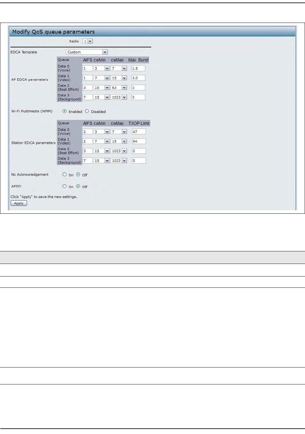
ConfiguringQualityofService
D-Link UnifiedAccessPointAdministrator’sGuide
November2011 Page103
UnifiedAccessPointAdministrator’sGuide
Figure31:ConfiguringQoSSettings
Table40:QoSSettings
Field Description
EDCATemplate Possibleoptionsare:Custom,Default,OptimizedforVoice.
AP EDCA Parameters
Queue QueuesaredefinedfordifferenttypesofdatatransmittedfromAP‐to‐station:
•Data0(Voice)—Highpriorityqueue,minimumdelay.Time‐sensitivedatasuch
asVoIPandstreamingmediaareautomaticallysenttothisqueue.
•Data1(Video)—Highpriorityqueue,minimumdelay.Time‐sensitivevideodata
isautomaticallysenttothisqueue.
•Data2(besteffort)—Mediumpriorityqueue,mediumthroughputanddelay.
MosttraditionalIPdataissenttothisqueue.
•Data3(Background)—Lowestpriorityqueue,highthroughput.Bulkdatathat
requiresmaximumthroughputandisnottime‐sensitiveissenttothisqueue
(FTPdata,forexample).
AIFS
(Inter‐FrameSpace)
TheArbitrationInter‐FrameSpacing(AIFS)specifiesawaittimefordataframes.
Thewaittimeismeasuredinslots.ValidvaluesforAIFSare1through255.

ConfiguringQualityofService
D-Link UnifiedAccessPointAdministrator’sGuide
November2011 Page104
UnifiedAccessPointAdministrator’sGuide
cwMin
(MinimumContention
Window)
Thisparameterisinputtothealgorithmthatdeterminestheinitialrandombackoff
waittime(window)forretryofatransmission.
ThevaluespecifiedforMinimumContentionWindowistheupperlimit(in
milliseconds)ofarangefromwhichtheinitialrandombackoffwaittimeis
determined.
Thefirstrandomnumbergeneratedwillbeanumberbetween0andthenumber
specifiedhere.
Ifthefirstrandombackoffwaittimeexpiresbeforethedataframeissent,aretry
counterisincrementedandtherandombackoffvalue(window)isdoubled.
Doublingwillcontinueuntilthesizeoftherandombackoffvaluereachesthe
numberdefinedintheMaximumContentionWindow.
ValidvaluesforcwMinare1,3,7,15,31,63,127,255,511,or1024.Thevaluefor
cwMinmustbelowerthanthevalueforcwMax.
cwMax
(MaximumContention
Window)
ThevaluespecifiedfortheMaximumContentionWindowistheupperlimit(in
milliseconds)forthedoublingoftherandombackoffvalue.Thisdoublingcontinues
untileitherthedataframeissentortheMaximumContentionWindowsizeis
reached.
OncetheMaximumContentionWindowsizeisreached,retrieswillcontinueuntila
maximumnumberofretriesallowedisreached.
ValidvaluesforcwMaxare1,3,7,15,31,63,127,255,511,or1024.Thevaluefor
cwMaxmustbehigherthanthevalueforcwMin.
Max.BurstLength TheMax.BurstLengthisanAPEDCAparameterandonlyappliestotrafficflowing
fromtheAPtotheclientstation.
Thisvaluespecifies(inmilliseconds)themaximumburstlengthallowedforpacket
burstsonthewirelessnetwork.Apacketburstisacollectionofmultipleframes
transmittedwithoutheaderinformation.Thedecreasedoverheadresultsinhigher
throughputandbetterperformance.
Validvaluesformaximumburstlengthare0.0through999.
Wi-Fi Multimedia Settings
Wi‐FiMultiMedia Wi‐FiMultiMedia(WMM)isenabledbydefault.WithWMMenabled,QoS
prioritizationandcoordinationofwirelessmediumaccessison.WithWMM
enabled,QoSsettingsontheUAPcontroldownstreamtrafficflowingfromtheAPto
clientstation(APEDCAparameters)andtheupstreamtrafficflowingfromthe
stationtotheAP(stationEDCAparameters).
DisablingWMMdeactivatesQoScontrolofstationEDCAparametersonupstream
trafficflowingfromthestationtotheAP.
WithWMMdisabled,youcanstillsetsomeparametersonthedownstreamtraffic
flowingfromtheAPtotheclientstation(APEDCAparameters).
TodisableWMMextensions,clickDisabled.
ToenableWMMextensions,clickEnabled.
Table40:QoSSettings(Cont.)
Field Description

ConfiguringQualityofService
D-Link UnifiedAccessPointAdministrator’sGuide
November2011 Page105
UnifiedAccessPointAdministrator’sGuide
Station EDCA Parameters
Queue Queuesaredefinedfordifferenttypesofdatatransmittedfromstation‐to‐AP:
•Data0(Voice)—Highestpriorityqueue,minimumdelay.Time‐sensitivedata
suchasVoIPandstreamingmediaareautomaticallysenttothisqueue.
•Data1(Video)—Highestpriorityqueue,minimumdelay.Time‐sensitivevideo
dataisautomaticallysenttothisqueue.
•Data2(besteffort)—Mediumpriorityqueue,mediumthroughputanddelay.
MosttraditionalIPdataissenttothisqueue.
•Data3(Background)—Lowestpriorityqueue,highthroughput.Bulkdatathat
requiresmaximumthroughputandisnottime‐sensitiveissenttothisqueue
(FTPdata,forexample).
AIFS
(Inter‐FrameSpace)
TheArbitrationInter‐FrameSpacing(AIFS)specifiesawaittimefordataframes.
Thewaittimeismeasuredinslots.ValidvaluesforAIFSare1through255.
cwMin
(MinimumContention
Window)
Thisparameterisusedbythealgorithmthatdeterminestheinitialrandombackoff
waittime(window)forretryofadatatransmissionduringaperiodofcontentionfor
UnifiedAccessPointresources.ThevaluespecifiedhereintheMinimumContention
Windowistheupperlimit(inmilliseconds)ofarangefromwhichtheinitialrandom
backoffwaittimewillbedetermined.Thefirstrandomnumbergeneratedwillbea
numberbetween0andthenumberspecifiedhere.Ifthefirstrandombackoffwait
timeexpiresbeforethedataframeissent,aretrycounterisincrementedandthe
randombackoffvalue(window)isdoubled.Doublingwillcontinueuntilthesizeof
therandombackoffvaluereachesthenumberdefinedintheMaximumContention
Window.
cwMax
(MaximumContention
Window)
ThevaluespecifiedhereintheMaximumContentionWindowistheupperlimit(in
milliseconds)forthedoublingoftherandombackoffvalue.Thisdoublingcontinues
untileitherthedataframeissentortheMaximumContentionWindowsizeis
reached.
OncetheMaximumContentionWindowsizeisreached,retrieswillcontinueuntila
maximumnumberofretriesallowedisreached.
TXOPLimit TheTXOPLimitisastationEDCAparameterandonlyappliestotrafficflowingfrom
theclientstationtotheAP.TheTransmissionOpportunity(TXOP)isanintervalof
time,inmilliseconds,whenaWMEclientstationhastherighttoinitiate
transmissionsontothewirelessmedium(WM)towardstheUnifiedAccessPoint.
TheTXOPLimitmaximumvalueis65535.
Other QoS Settings
NoAcknowledgement SelectOntospecifythattheAPshouldnotacknowledgeframeswithQosNoAckas
theserviceclassvalue.
APSD SelectOntoenableAutomaticPowerSaveDelivery(APSD),whichisapower
managementmethod.APSDisrecommendedifVoIPphonesaccessthenetwork
throughtheAP.
Note:AfteryouconfiguretheQoSsettings,youmustclickApplytoapplythechangesandtosavethe
settings.ChangingsomesettingsmightcausetheAPtostopandrestartsystemprocesses.Ifthis
happens,wirelessclientswilltemporarilyloseconnectivity.WerecommendthatyouchangeAP
settingswhenWLANtrafficislow.
Table40:QoSSettings(Cont.)
Field Description
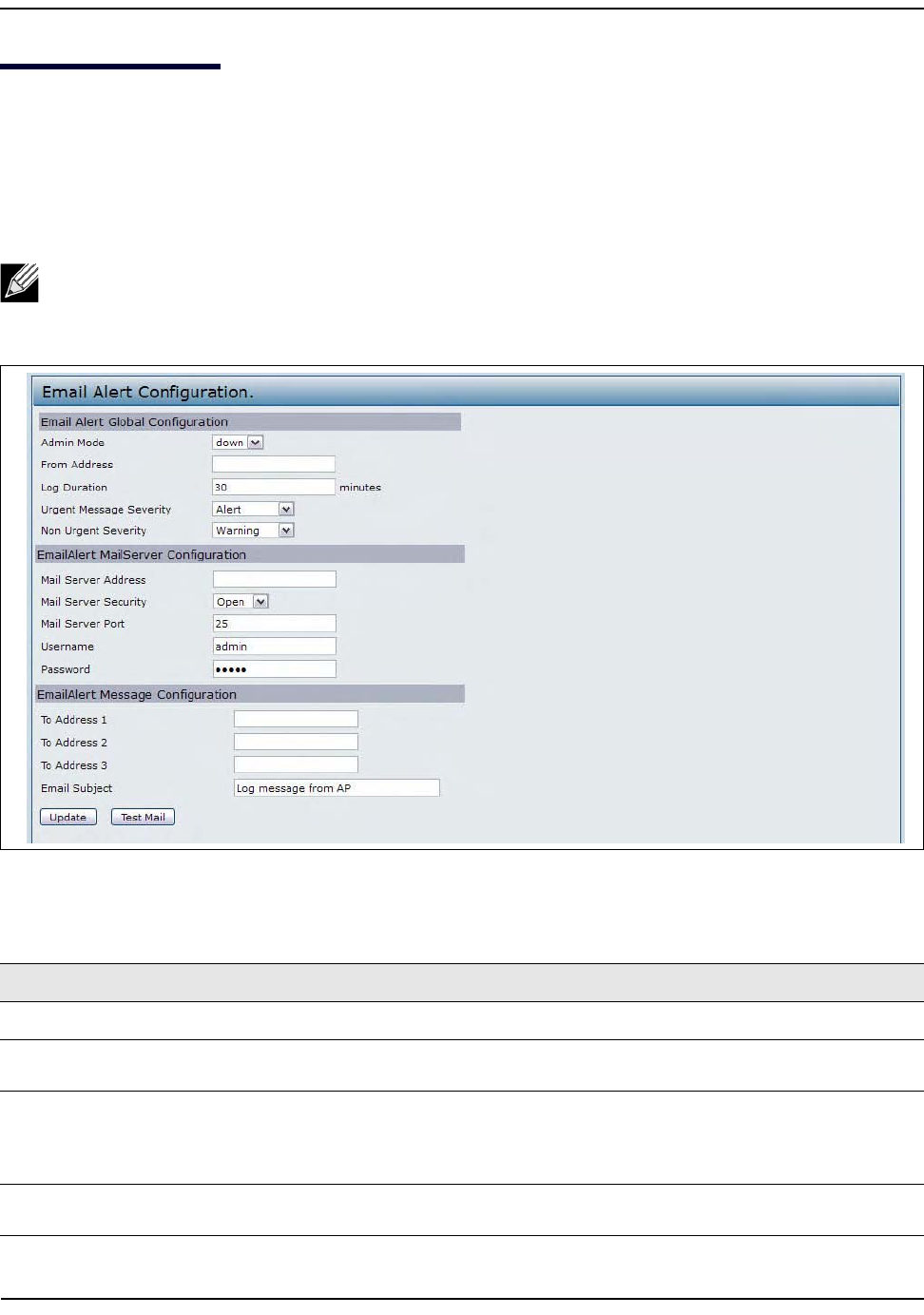
ConfiguringEmailAlert
D-Link UnifiedAccessPointAdministrator’sGuide
November2011 Page106
UnifiedAccessPointAdministrator’sGuide
ConfiguringEmailAlert
TheEmailAlertfeatureallowstheAPtoautomaticallysendemailmessageswhenaneventatorabovethe
configuredseverityleveloccurs.UsetheEmailAlertConfigurationpagetoconfiguremailserversettings,toset
theseveritylevelthattriggersalerts,andtoadduptothreeemailaddresseswhereurgentandnon‐urgent
emailalertsaresent.
Figure32:ConfiguringEmailAlert
Note:EmailalertisoperationallydisabledwhentheAPtransitionstomanagedmode.
Table41:EmailAlertConfiguration
Field Description
EmailAlertGlobalConfiguration
AdminMode GloballyenableordisabletheEmailAlertfeatureontheAP.Bydefault,emailalerts
aredisabled.
FromAddress SpecifytheemailaddressthatappearsintheFromfieldofalertmessagessentfrom
theAP,forexampledlinkAP23@foo.com.Theaddresscanbeamaximumof255
charactersandcancontainonlyprintablecharacters.Bydefault,noaddressis
configured.
LogDuration Thisduration,inminutes,determineshowfrequentlythenoncriticalmessagesare
senttotheSMTPServer.Therangeis30‐1440minutes.Thedefaultis30minutes.
ConfiguringEmailAlert
D-Link UnifiedAccessPointAdministrator’sGuide
November2011 Page107
UnifiedAccessPointAdministrator’sGuide
UrgentMessage
Severity
Configurestheseveritylevelforlogmessagesthatareconsideredtobeurgent.
Messagesinthiscategoryaresentimmediately.Thesecuritylevelyouselectandall
higherlevelsareurgent:
•Emergencyindicatessystemisunusable.Itisthehighestlevelofseverity.
•Alertindicatesactionmustbetakenimmediately.
•C
riticalindicatescriticalconditions.
•Errorindicateserrorconditions.
•Warningindicateswarningconditions.
• Noticeindicatesnormalbutsignificantconditions.
• Informationalindicatesinformationalmessages.
• Debugindicatesdebug‐levelmessages.
NonUrgentSeverity Configurestheseveritylevelforlogmessagesthatareconsideredtobenonurgent.
Messagesinthiscategoryarecollectedandsentinadigestformatthetimeinterval
specifiedbytheLogDurationfield.Thesecuritylevelyouselectandalllevelsupto,
butnotincludingthelowestUrgentlevelareconsiderednonurgent.Messages
belowthesecuritylevelyouspecifyarenotsentviaemail.
SeetheUrgentMessagefielddescriptionforinformationaboutthesecuritylevels.
EmailAlertMailServerConfiguration
MailServerAddress SpecifytheIPaddressorhostnameoftheSMTPserveronthenetwork.
MailServerSecurity SpecifywhethertouseSMTPoverSSL(TLSv1)ornosecurity(Open)for
authenticationwiththemailserver.ThedefaultisOpen.
MailServerPort ConfigurestheTCPportnumberforSMTP.Therangeisavalidportnumberfrom0
to65535.Thedefaultis25,whichisthestandardportforSMTP.
Username Specifytheusernametousewhenauthenticationwiththemailserverisrequired.
Theusernameisa64‐bytecharacterstringwithallprintablecharacters.Thedefault
isadmin.
Password Specifythepasswordassociatedwiththeusernameconfiguredinthepreviousfield.
EmailAlertMessageConfiguration
ToAddress1Configurethefirstemailaddresstowhichalertmessagesaresent.Theaddressmust
beavalidemailaddress.Bydefault,noaddressisconfigured.
ToAddress2Optionally,configurethesecondemailaddresstowhichalertmessagesaresent.The
addressmustbeavalidemailaddress.Bydefault,noaddressisconfigured.
ToAddress3Optionally,configurethethirdemailaddresstowhichalertmessagesaresent.The
addressmustbeavalidemailaddress.Bydefault,noaddressisconfigured.
EmailSubject Specifythetexttobedisplayedinthesubjectoftheemailalertmessage.Thesubject
cancontainupto255alphanumericcharacters.ThedefaultisLogmessagefromAP.
Note:AfteryouconfiguretheEmailAlertsettings,clickApplytoapplythechangesandtosavethe
settings.
Table41:EmailAlertConfiguration(Cont.)
Field Description

ConfiguringEmailAlert
D-Link UnifiedAccessPointAdministrator’sGuide
November2011 Page108
UnifiedAccessPointAdministrator’sGuide
Tovalidatetheconfiguredemailservercredentials,clickTestMail.Youcansendatestemailoncetheemail
serverdetailsareconfigured.
ThefollowingtextshowsanexampleofanemailalertsentfromtheAPtothenetworkadministrator:
From:AP‐192.168.2.10@mailserver.com
Sent:Wednesday,July08,201111:16AM
To:administrator@mailserver.com
Subject:logmessagefromAP
TIMEPriorityProcessIdMessage
Jul803:48:25infologin[1457]rootloginon‘ttyp0’
Jul803:48:26infomini_http‐ssl[1175]Maxconcurrentconnectionsof20reached
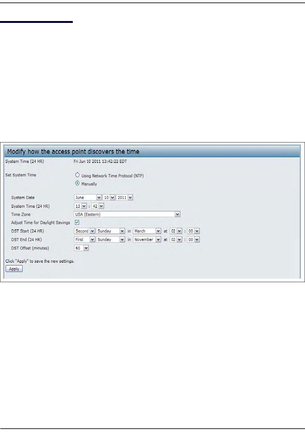
EnablingtheTimeSettings(NTP)
D-Link UnifiedAccessPointAdministrator’sGuide
November2011 Page109
UnifiedAccessPointAdministrator’sGuide
EnablingtheTimeSettings(NTP)
UsetheTimeSettingspagetospecifytheNetworkTimeProtocol(NTP)servertousetoprovidetimeanddate
informationtotheAPortoconfigurethetimeanddateinformationmanually.
NTPisanInternetstandardprotocolthatsynchronizescomputerclocktimesonyournetwork.NTPservers
transmitCoordinatedUniversalTime(UTC,alsoknownasGreenwichMeanTime)totheirclientsystems.NTP
sendsperiodictimerequeststoservers,usingthereturnedtimestamptoadjustitsclock.Thetimestampis
usedtoindicatethedateandtimeofeacheventinlogmessages.
Seehttp://www.ntp.orgformoreinformationaboutNTP.
TosetthesystemtimeeithermanuallyorbyspecifyingtheaddressoftheNTPserverfortheAPtouse,click
theServices>TimeSettings(NTP)tabandupdatethefieldsasdescribedinTable42onpage110.
Figure33:SettingtheSystemTime
EnablingtheTimeSettings(NTP)
D-Link UnifiedAccessPointAdministrator’sGuide
November2011 Page110
UnifiedAccessPointAdministrator’sGuide
Table42:NTPSettings
Field Description
SetSystemTime NTPprovidesawayfortheAPtoobtainandmaintainitstimefromaserveron
thenetwork.UsinganNTPservergivesyourAPtheabilitytoprovidethe
correcttimeofdayinlogmessagesandsessioninformation.
Choosetouseanetworktimeprotocol(NTP)servertodeterminethesystem
time,orsetthesystemtimemanually:
•TopermittheAPtopollanNTPserver,clickUsingNetworkTimeProtocol
(NTP).
•TopreventtheAPfrompollinganNTPserver,clickManually.
NTPServer(UseNTP) IfNTPisenabled,specifytheNTPservertouse.
YoucanspecifytheNTPserverbyhostnameorIPaddress,althoughusingthe
IPaddressisnotrecommendedasthesecanchangemorereadily.
Ifyouspecifyahostname,notethefollowingrequirements:
•Thelengthmustbebetween1–63characters.
• Upperandlowercasecharacters,numbers,andhyphensareaccepted.
•Thefirstcharactermustbealetter(a–zorA–Z),andthelastcharacter
cannotbeahyphen.
SystemDate(Manual
configuration)
Specifythecurrentmonth,day,andyear.
SystemTime(Manual
configuration)
Specifythecurrenttimeinhoursandminutes.Thesystemusesa24‐hour
clock,so6:00PMisconfiguredas18:00.
TimeZone Selectyourlocaltimezonefromthemenu.ThedefaultisUSA(Pacific).
AdjustTimeforDaylight
Savings
SelecttohavethesystemadjustthereportedtimeforDaylightSavingsTime
(DST).Whenthisfieldisselected,fieldstoconfigureDaylightSavingsTime
settingsappear.
DSTStart(24HR) ConfigurethedateandtimetobeginDaylightSavingsTimefortheSystem
Time.
DSTEnd(24HR) ConfigurethedateandtimetoendDaylightSavingsTimefortheSystemTime.
DSTOffset(minutes) SelectthenumberofminutestooffsetDST.Thedefaultis60minutes.
Note:AfteryouconfiguretheTimesettings,youmustclickApplytoapplythechangesandtosave
thesettings.ChangingsomesettingsmightcausetheAPtostopandrestartsystemprocesses.Ifthis
happens,wirelessclientswilltemporarilyloseconnectivity.WerecommendthatyouchangeAP
settingswhenWLANtrafficislow.
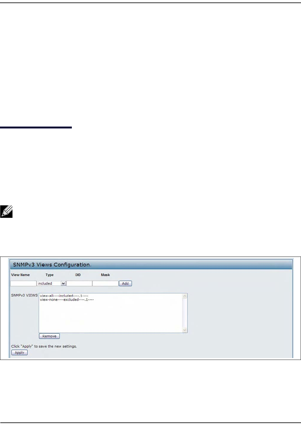
ConfiguringSNMPv3
D-Link UnifiedAccessPointAdministrator’sGuide
November2011 Page111
UnifiedAccessPointAdministrator’sGuide
Section6:ConfiguringSNMPv3
ThissectiondescribeshowtoconfiguretheSNMPv3settingsontheUAPandcontainsthefollowing
subsections:
•ConfiguringSNMPv3Views
•ConfiguringSNMPv3Groups
•ConfiguringSNMPv3Users
•ConfiguringSNMPv3Targets
ConfiguringSNMPv3Views
AMIBviewiscombinationofasetofviewsubtreesorafamilyofviewsubtreeswhereeachviewsubtreeisa
subtreewithinthemanagedobjectnamingtree.YoucancreateMIBviewstocontroltheOIDrangethat
SNMPv3userscanaccess.
AMIBviewcalled"all"iscreatedbydefaultinthesystem.Thisviewcontainsallmanagementobjects
supportedbythesystem.
Figure34:SNMPv3Views
Note:Ifyoucreateanexcludedviewsubtree,createacorrespondingincludedentrywiththesame
viewnametoallowsubtreesoutsideoftheexcludedsubtreetobeincluded.Forexample,tocreatea
viewthatexcludesthesubtree1.3.6.1.4,createanexcludedentrywiththeOID1.3.6.1.4.Then,create
anincludedentrywithOID.1withthesameviewname.
ConfiguringSNMPv3Views
D-Link UnifiedAccessPointAdministrator’sGuide
November2011 Page112
UnifiedAccessPointAdministrator’sGuide
Table43describesthefieldsyoucanconfigureontheSNMPv3Viewspage.
Table43:SNMPv3Views
Field Description
ViewName EnteranametoidentifytheMIBview.
Viewnamescancontainupto32alphanumericcharacters.
Type Specifieswhethertoincludeorexcludetheviewsubtreeorfamilyofsubtreesfromthe
MIBview.
OID EnteranOIDstringforthesubtreetoincludeorexcludefromtheview.
Forexample,thesystemsubtreeisspecifiedbytheOIDstring.1.3.6.1.2.1.1.
Mask TheOIDmaskis47charactersinlength.TheformatoftheOIDmaskisxx.xx.xx(.)...or
xx:xx:xx....(:)andis16octetsinlength.Eachoctetis2hexadecimalcharactersseparated
byeither.(period)or:(colon).Onlyhexcharactersareacceptedinthisfield.For
example,OIDmaskFA.80is11111010.10000000.
Afamilymaskisusedtodefineafamilyofviewsubtrees.Thefamilymaskindicateswhich
sub‐identifiersoftheassociatedfamilyOIDstringaresignificanttothefamily's
definition.
Afamilyofviewsubtreesallowscontrolaccesstoonerowinatable,inamoreefficient
manner.
SNMPv3Views ThisfieldshowstheMIBviewsontheUAP.Toremoveaview,selectitandclickRemove.
Note:AfteryouconfiguretheSNMPv3Viewssettings,youmustclickApplytoapplythechangesand
tosavethesettings.
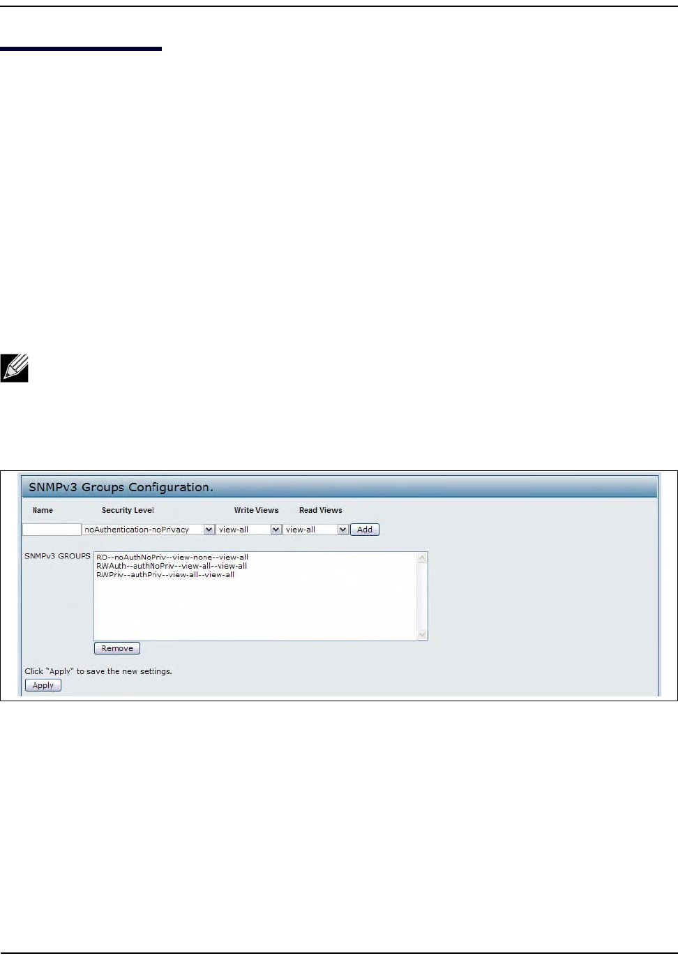
ConfiguringSNMPv3Groups
D-Link UnifiedAccessPointAdministrator’sGuide
November2011 Page113
UnifiedAccessPointAdministrator’sGuide
ConfiguringSNMPv3Groups
SNMPv3groupsallowyoutocombineusersintogroupsofdifferentauthorizationandaccessprivileges.
Bydefault,theUAPhastwogroups:
•RO—Aread‐onlygroupusingauthenticationanddataencryption.UsersinthisgroupuseanMD5key/
passwordforauthenticationandaDESkey/passwordforencryption.BoththeMD5andDESkey/
passwordsmustbedefined.Bydefault,usersofthisgroupwillhavereadonlyaccesstothedefaultallMIB
view,whichcanbemodifiedbytheuser.
•RW—Aread/writegroupusingauthenticationanddataencryption.UsersinthisgroupuseanMD5key/
passwordforauthenticationandaDESkey/passwordforencryption.BoththeMD5andDESkey/
passwordsmustbedefined.Bydefault,usersofthisgroupwillhavereadandwriteaccesstothedefault
allMIBview,whichcanbemodifiedbytheuser.
RWandROgroupsaredefinedbydefault.
Todefineadditionalgroups,navigatetotheSNMPv3GroupspageandconfigurethesettingsthatTable44on
page114describes.
Figure35:SNMPv3Groups
Note:TheUAPsupportsmaximumofeightgroups.
ConfiguringSNMPv3Groups
D-Link UnifiedAccessPointAdministrator’sGuide
November2011 Page114
UnifiedAccessPointAdministrator’sGuide
Table44:SNMPv3Groups
Field Description
Name Specifyanametousetoidentifythegroup.ThedefaultgroupnamesareRWandRO.
Groupnamescancontainupto32alphanumericcharacters.
SecurityLevel Selectoneofthefollowingsecuritylevelsforthegroup:
•noAuthentication‐noPrivacy—Noauthenticationandnodataencryption(no
security).
•Authentication‐noPrivacy—Authentication,butnodataencryption.Withthis
securitylevel,userssendSNMPmessagesthatuseanMD5key/passwordfor
authentication,butnotaDESkey/passwordforencryption.
•Authentication‐Privacy—Authenticationanddataencryption.Withthissecurity
level,userssendanMD5key/passwordforauthenticationandaDESkey/password
forencryption.
Forgroupsthatrequireauthentication,encryption,orboth,youmustdefinetheMD5
andDESkey/passwordsontheSNMPv3Userspage.
WriteViews Selectthewriteaccesstomanagementobjects(MIBs)forthegroup:
•write‐all—Thegroupcancreate,alter,anddeleteMIBs.
•write‐none—Thegroupisnotallowedtocreate,alter,ordeleteMIBS.
ReadViews Selectthereadaccesstomanagementobjects(MIBs)forthegroup:
•view‐all—ThegroupisallowedtoviewandreadallMIBs.
•view‐none—ThegroupcannotvieworreadMIBs.
SNMPv3Groups ThisfieldshowsthedefaultgroupsandthegroupsthatyouhavedefinedontheAP.To
removeagroup,selectthegroupandclickRemove.
Note:AfteryouconfiguretheSNMPv3Groupssettings,youmustclickApplytoapplythechangesand
tosavethesettings.
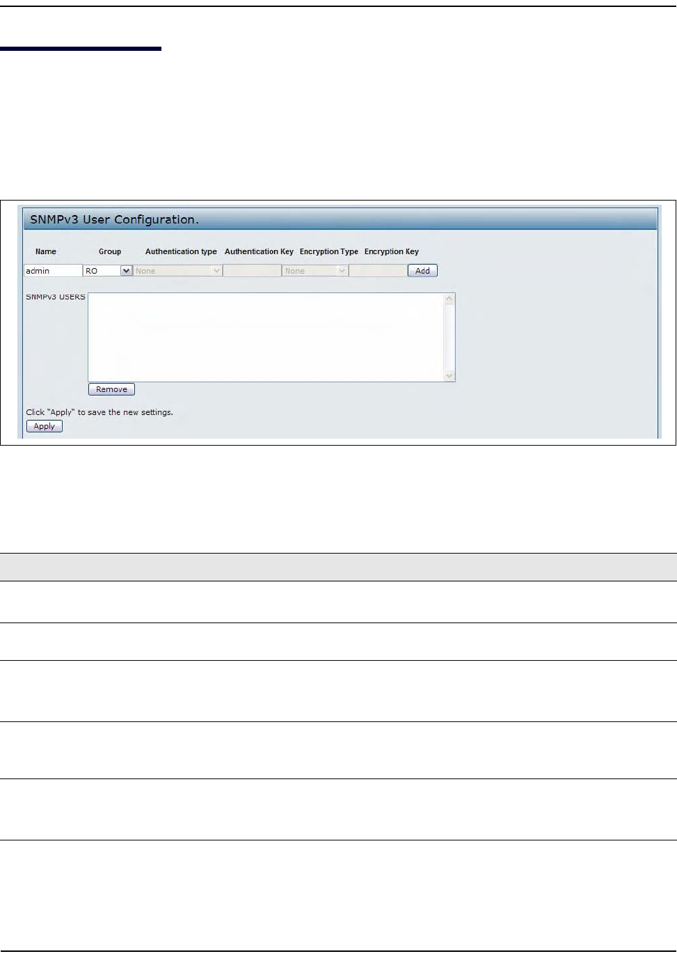
ConfiguringSNMPv3Users
D-Link UnifiedAccessPointAdministrator’sGuide
November2011 Page115
UnifiedAccessPointAdministrator’sGuide
ConfiguringSNMPv3Users
FromtheSNMPv3Userspage,youcandefinemultipleusers,associatethedesiredsecurityleveltoeachuser,
andconfiguresecuritykeys.
Forauthentication,onlyMD5typeissupported,andforencryptiononlyDEStypeissupported.Thereareno
defaultSNMPv3usersontheUAP.
Figure36:SNMPv3Users
Table45describesthefieldstoconfigureSNMPv3users.
Table45:SNMPv3Users
Field Description
Name EntertheusernametoidentifytheSNMPv3user.
Usernamescancontainupto32alphanumericcharacters.
Group Maptheusertoagroup.ThedefaultgroupsareRWAuth,RWPriv,andRO.Youcan
defineadditionalgroupsontheSNMPv3Groupspage.
AuthenticationType SelectthetypeofauthenticationtouseonSNMPrequestsfromtheuser:
•MD5—RequireMD5authenticationonSNMPv3requestsfromtheuser.
•None—SNMPv3requestsfromthisuserrequirenoauthentication.
AuthenticationKey IfyouspecifyMD5astheauthenticationtype,enterapasswordtoenabletheSNMP
agenttoauthenticaterequestssentbytheuser.
Thepassphrasemustbebetween8and32charactersinlength.
EncryptionType SelectthetypeofprivacytouseonSNMPrequestsfromtheuser:
•DES—UseDESencryptiononSNMPv3requestsfromtheuser.
•None—SNMPv3requestsfromthisuserrequirenoprivacy.
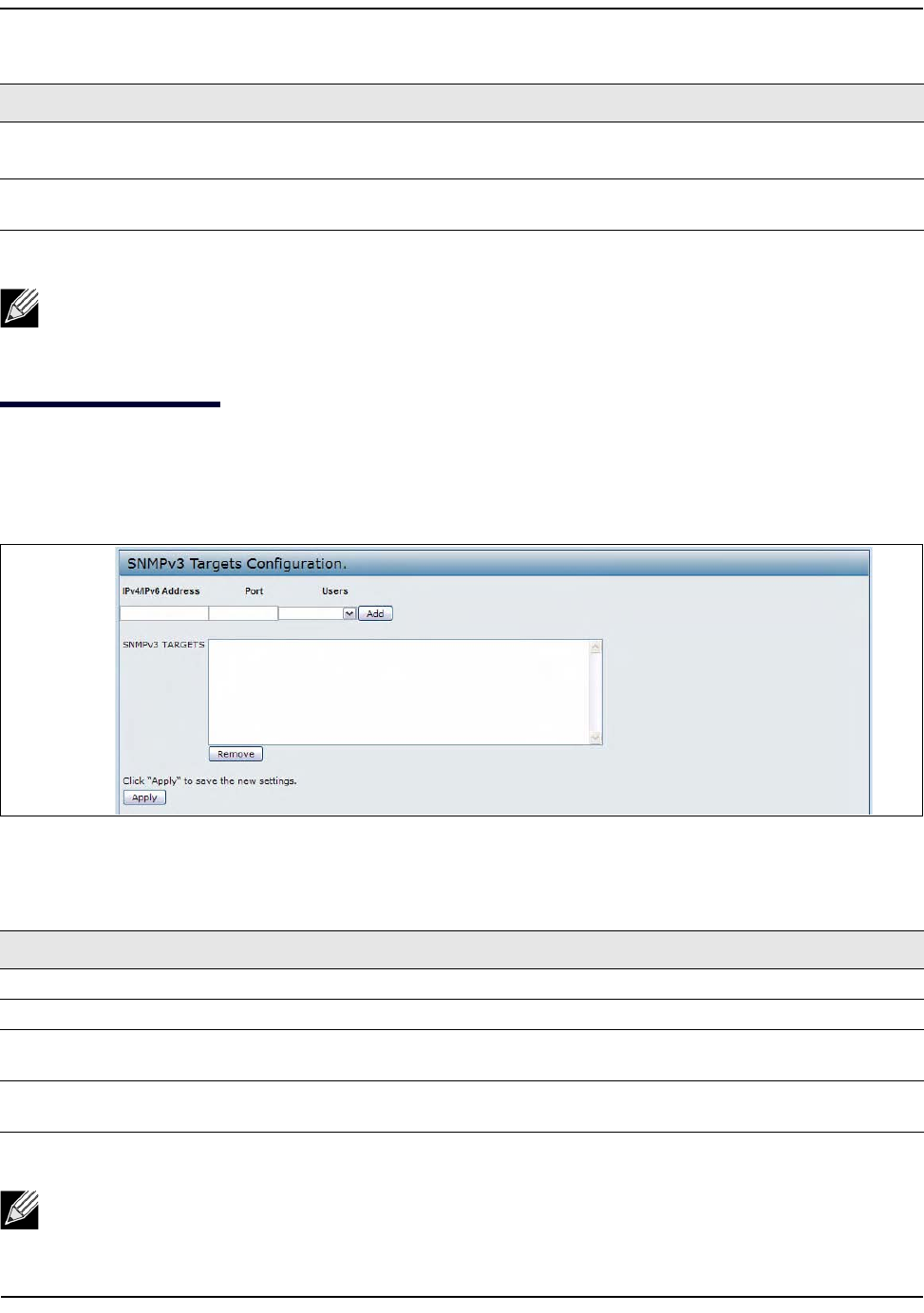
ConfiguringSNMPv3Targets
D-Link UnifiedAccessPointAdministrator’sGuide
November2011 Page116
UnifiedAccessPointAdministrator’sGuide
ConfiguringSNMPv3Targets
SNMPv3Targetssend"inform"messagestotheSNMPmanager.Eachtargetisidentifiedbyatargetnameand
associatedwithtargetIPaddress,UDPport,andSNMPusername.
Figure37:SNMPv3Target
EncryptionKey IfyouspecifyDESastheprivacytype,enterakeytousetoencrypttheSNMPrequests.
Thepassphrasemustbebetween8and32charactersinlength.
SNMPv3Users ThisfieldshowstheusersthatyouhavedefinedontheAP.To removeauser,selectthe
userandclickRemove.
Note:AfteryouconfiguretheSNMPv3Userssettings,youmustclickApplytoapplythechangesand
tosavethesettings.
Table46:SNMPv3Targets
Field Description
IPAddress EntertheIPaddressoftheremoteSNMPmanagertoreceivethetarget.
Port EntertheUDPporttouseforsendingSNMPtargets.
Users EnterthenameoftheSNMPusertoassociatewiththetarget.ToconfigureSNMPusers,
see“ConfiguringSNMPv3Users”onpage115.
SNMPv3Targets ThisfieldshowstheSNMPv3TargetsontheUAP.Toremoveatarget,selectitandclick
Remove.
Note:AfteryouconfiguretheSNMPv3Targetsettings,youmustclickApplytoapplythechangesand
tosavethesettings.
Table45:SNMPv3Users(Cont.)
Field Description
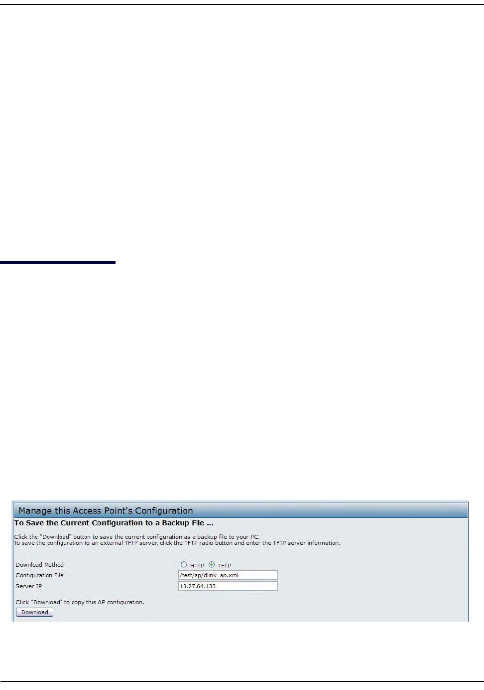
MaintainingtheAccessPoint
D-Link UnifiedAccessPointAdministrator’sGuide
November2011 Page117
UnifiedAccessPointAdministrator’sGuide
Section7:MaintainingtheAccessPoint
ThissectiondescribeshowtomaintaintheUAP.
FromtheUAPAdministratorUI,youcanperformthefollowingmaintenancetasks:
•“SavingtheCurrentConfigurationtoaBackupFile”
•“RestoringtheConfigurationfromaPreviouslySavedFile”
•“PerformingAPMaintenance”
–“ResettingtheFactoryDefaultConfiguration”
–“RebootingtheAccessPoint”
•“UpgradingtheFirmware”
•“PacketCaptureConfigurationandSettings”
SavingtheCurrentConfigurationtoaBackupFile
TheAPconfigurationfileisinXMLformatandcontainsalloftheinformationabouttheAPsettings.Youcan
downloadtheconfigurationfiletoamanagementstationtomanuallyeditthecontentortosaveasaback‐up
copy.
YoucanuseHTTPorTFTPtotransferfilestoandfromtheUAP.Afteryoudownloadaconfigurationfiletothe
managementstation,youcanmanuallyeditthefile,whichisinXMLformat.Then,youcanuploadtheedited
configurationfiletoapplythoseconfigurationsettingstotheAP.
UsethefollowingstepstosaveacopyofthecurrentsettingsonanAPtoabackupconfigurationfilebyusing
TFTP:
1. SelectTFTPforDownloadMethod.
2. Enteraname(1to63characters)forthebackupfileintheFilenamefield,includingthe.xmlfilename
extensionandthepathtothedirectorywhereyouwanttosavethefile.
3. EntertheIPaddressoftheTFTPserver.
.
4. ClickDownloadtosaveacopyofthefiletotheTFTPserver.
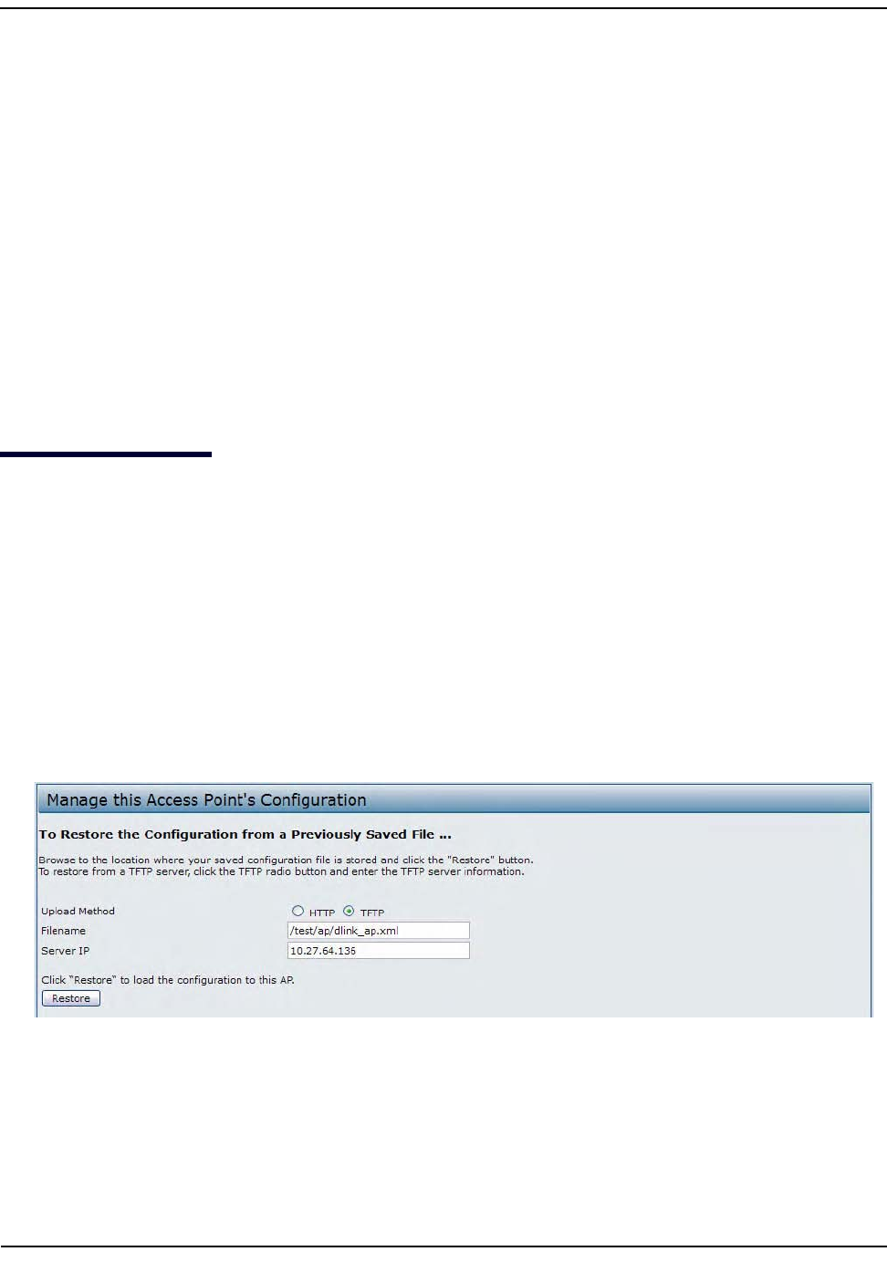
RestoringtheConfigurationfromaPreviouslySavedFile
D-Link UnifiedAccessPointAdministrator’sGuide
November2011 Page118
UnifiedAccessPointAdministrator’sGuide
UsethefollowingstepstosaveacopyofthecurrentsettingsonanAPtoabackupconfigurationfilebyusing
HTTP:
1. SelectHTTPforDownloadMethod.
2. ClicktheDownloadbutton.
Adialogboxdisplaysverifyingthedownload.
3. Toproceedwiththedownload,selectOK.
Adialogboxopensallowingyoutovieworsavethefile.
4. SelecttheSaveFileoptionandselectOK.
5. Usethefilebrowsertonavigatetothedirectorywhereyouwanttosavethefile,andclickOKtosavethe
file.
Youcankeepthedefaultfilename(config.xml)orrenamethebackupfile,butbesuretosavethefilewith
an.xmlextension.
RestoringtheConfigurationfromaPreviouslySavedFile
YoucanuseHTTPorTFTPtotransferfilestoandfromtheUAP.Afteryoudownloadaconfigurationfiletothe
managementstation,youcanmanuallyeditthefile,whichisinXMLformat.Then,youcanuploadtheedited
configurationfiletoapplythoseconfigurationsettingstotheAP.
UsethefollowingprocedurestorestoretheconfigurationonanAPtopreviouslysavedsettingsbyusingTFTP:
1. SelectTFTPforUploadMethod.
2. Enteraname(1to63characters)forthebackupfileintheFilenamefield,includingthe.xmlfilename
extensionandthepathtothedirectorythatcontainstheconfigurationfiletoupload.
3. EntertheIPaddressoftheTFTPserverintheServerIPfield.
4. ClicktheRestorebutton.
TheAPreboots.Arebootconfirmationdialogandfollow‐onrebootingstatusmessagedisplays.Pleasewait
fortherebootprocesstocomplete,whichmighttakeseveralminutes.
TheAdministrationWebUIisnotaccessibleuntiltheAPhasrebooted.

RestoringtheConfigurationfromaPreviouslySavedFile
D-Link UnifiedAccessPointAdministrator’sGuide
November2011 Page119
UnifiedAccessPointAdministrator’sGuide
UsethefollowingstepstosaveacopyofthecurrentsettingsonanAPtoabackupconfigurationfilebyusing
HTTP:
1. SelectHTTPforUploadMethod.
2. UsertheBrowsebuttontoselectthefiletorestore.
3. ClicktheRestorebutton.
AFileUploadorChooseFiledialogboxdisplays.
4. Navigatetothedirectorythatcontainsthefile,thenselectthefiletouploadandclickOpen.
(OnlythosefilescreatedwiththeBackupfunctionandsavedas.xmlbackupconfigurationfilesarevalidto
usewithRestore;forexample,ap_config.xml.)
5. ClicktheRestorebutton.
Adialogboxopensverifyingtherestore.
6. ClickOKtoproceed.
TheAPreboots.Arebootconfirmationdialogandfollow‐onrebootingstatusmessagedisplays.Pleasewait
fortherebootprocesstocomplete,whichmighttakeseveralminutes.
TheAdministrationWebUIisnotaccessibleuntiltheAPhasrebooted.
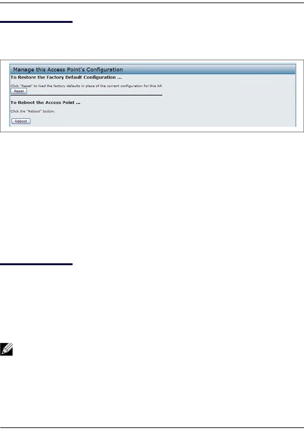
PerformingAPMaintenance
D-Link UnifiedAccessPointAdministrator’sGuide
November2011 Page120
UnifiedAccessPointAdministrator’sGuide
PerformingAPMaintenance
FromtheMaintenancepage,youcanresettheAPtoitsfactorydefaultsettingsorreboottheAP.
Figure38:Maintenance
ResettingtheFactoryDefaultConfiguration
IfyouareexperiencingproblemswiththeUAPandhavetriedallothertroubleshootingmeasures,clickReset.
Thisrestoresfactorydefaultsandclearsallsettings,includingsettingssuchasanewpasswordorwireless
settings.Youcanalsousetheresetbuttononthebackpaneltoresetthesystemtothedefaultconfiguration.
RebootingtheAccessPoint
Formaintenancepurposesorasatroubleshootingmeasure,youcanreboottheUAP.ToreboottheAP,click
theRebootbuttonontheConfigurationpage.
UpgradingtheFirmware
AsnewversionsoftheUAPfirmwarebecomeavailable,youcanupgradethefirmwareonyourdevicestotake
advantageofnewfeaturesandenhancements.TheAPusesaTFTPclientforfirmwareupgrades.Youcanalso
useHTTPtoperformfirmwareupgrades.
Afteryouuploadnewfirmwareandthesystemreboots,thenewlyaddedfirmwarebecomestheprimary
image.Iftheupgradefails,theoriginalfirmwareremainsastheprimaryimage.
UsethefollowingstepstoupgradethefirmwareonanaccesspointbyusingTFTP:
1. SelectTFTPforUploadMethod.
2. Enteraname(1to63characters)fortheimagefileintheImageFilenamefield,includingthepathtothe
directorythatcontainstheimagetoupload.
Note:Whenyouupgradethefirmware,theaccesspointretainstheexistingconfiguration
information.
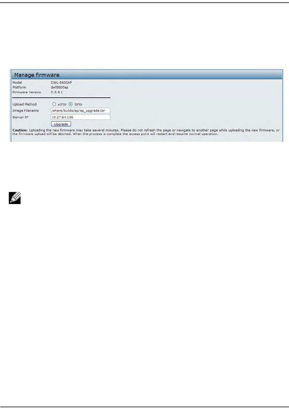
UpgradingtheFirmware
D-Link UnifiedAccessPointAdministrator’sGuide
November2011 Page121
UnifiedAccessPointAdministrator’sGuide
Forexample,touploadtheap_upgrade.tarimagelocatedinthe/share/builds/apdirectory,enter/share/
builds/ap/ap_upgrade.tarintheImageFilenamefield.
Thefirmwareupgradefilesuppliedmustbeatarfile.Donotattempttousebinfilesorfilesofother
formatsfortheupgrade;thesetypesoffileswillnotwork.
3. EntertheIPaddressoftheTFTPserver.
4. ClickUpgrade.
UponclickingUpgradeforthefirmwareupgrade,apopupconfirmationwindowisdisplayedthatdescribes
theupgradeprocess.
5. ClickOKtoconfirmtheupgradeandstarttheprocess.
Theupgradeprocessmaytakeseveralminutesduringwhichtimetheaccesspointwillbeunavailable.Do
notpowerdowntheaccesspointwhiletheupgradeisinprocess.Whentheupgradeiscomplete,the
accesspointrestarts.TheAPresumesnormaloperationwiththesameconfigurationsettingsithadbefore
theupgrade.
6. Toverifythatthefirmwareupgradecompletedsuccessfully,checkthefirmwareversionshownonthe
Upgradepage(ortheBasicSettingspage).Iftheupgradewassuccessful,theupdatedversionnameor
numberisindicated.
UsethefollowingstepstoupgradethefirmwareonanaccesspointbyusingHTTP:
1. SelectHTTPforUploadMethod.
2. Ifyouknowthepathtothenewfirmwareimagefile,enteritintheImageFilenamefield.Otherwise,click
theBrowsebuttonandlocatethefirmwareimagefile.
Thefirmwareupgradefilesuppliedmustbeatarfile.Donotattempttousebinfilesorfilesofother
formatsfortheupgrade;thesetypesoffileswillnotwork.
3. ClickUpgradetoapplythenewfirmwareimage.
UponclickingUpgradeforthefirmwareupgrade,apopupconfirmationwindowisdisplayedthatdescribes
theupgradeprocess.
4. ClickOKtoconfirmtheupgradeandstarttheprocess.
Note:ThefirmwareupgradeprocessbeginsonceyouclickUpgradeandthenOKinthepopup
confirmationwindow.

PacketCaptureConfigurationandSettings
D-Link UnifiedAccessPointAdministrator’sGuide
November2011 Page122
UnifiedAccessPointAdministrator’sGuide
Theupgradeprocessmaytakeseveralminutesduringwhichtimetheaccesspointwillbeunavailable.Do
notpowerdowntheaccesspointwhiletheupgradeisinprocess.Whentheupgradeiscomplete,the
accesspointrestarts.TheAPresumesnormaloperationwiththesameconfigurationsettingsithadbefore
theupgrade.
5. Toverifythatthefirmwareupgradecompletedsuccessfully,checkthefirmwareversionshownonthe
Upgradepage(ortheBasicSettingspage).Iftheupgradewassuccessful,theupdatedversionnameor
numberisindicated.
PacketCaptureConfigurationandSettings
Wirelesspacketcaptureoperatesintwomodes:
•Capturefilemode
•Remotecapturemode
Forcapturefilemode,capturedpacketsarestoredinafileontheAccessPoint.TheAPcantransferthefileto
aTFTPserver.ThefileisformattedinpcapformatandcanbeexaminedusingtoolssuchasWiresharkand
OmniPeek.
Forremotecapturemode,thecapturedpacketsareredirectedinrealtimetoanexternalPCrunningthe
Wireshark®tool.
TheAPcancapturethefollowingtypesofpackets:
•802.11packetsreceivedandtransmittedonradiointerfaces.Packetscapturedonradiointerfacesinclude
the802.11header.
•802.3packetsreceivedandtransmittedontheEthernetinterface.
•802.3packetsreceivedandtransmittedontheinternallogicalinterfacessuchasVAPsandWDSinterfaces.
FromthePacketCaptureConfigurationandSettingspage,youcan:
• Viewthecurrentpacketcapturestatus.
• Configurepacketcaptureparameters.
• Configurepacketfilecapture.
• Configurearemotecaptureport.
•Downloadapacketcapturefile.
Note:ThefirmwareupgradeprocessbeginsonceyouclickUpgradeandthenOKinthepopup
confirmationwindow.
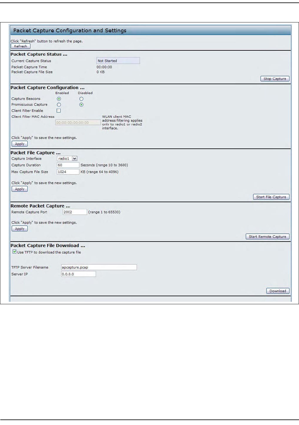
PacketCaptureConfigurationandSettings
D-Link UnifiedAccessPointAdministrator’sGuide
November2011 Page123
UnifiedAccessPointAdministrator’sGuide
Figure39:PacketCaptureConfiguration
PacketCaptureConfigurationandSettings
D-Link UnifiedAccessPointAdministrator’sGuide
November2011 Page124
UnifiedAccessPointAdministrator’sGuide
PacketCaptureStatus
PacketCaptureStatusallowsyoutoviewthestatusofpacketcaptureontheAP.
Table47describesinformationthepacketcapturestatusfieldsdisplay.
PacketCaptureParameterConfiguration
PacketCaptureConfigurationallowsyoutoconfigureparametersthataffecthowpacketcapturefunctionson
theradiointerfaces.
Table48describesthefieldstoconfigurethepacketcapture.
Table47:PacketCaptureStatus
Field Description
CurrentCaptureStatus Showswhetherpacketcaptureisrunningorstopped.
PacketCaptureTime Showselapsedcapturetime.
PacketCaptureFileSize Showsthecurrentcapturefilesize.
Table48:PacketCaptureConfiguration
Field Description
CaptureBeacons Enabletocapturethe802.11beaconsdetectedortransmittedbytheradio.
PromiscuousCapture Enabletoplacetheradioinpromiscuousmodewhenthecaptureisactive.
Inpromiscuousmodetheradioreceivesalltrafficonthechannel,including
trafficthatisnotdestinedtothisAP.Whiletheradioisoperatingin
promiscuousmode,itcontinuesservingassociatedclients.Packetsnot
destinedtotheAParenotforwarded.
Assoonasthecaptureiscompleted,theradiorevertstonon‐promiscuous
modeoperation.
ClientFilterEnable EnabletousetheWLANclientfiltertocaptureonlyframesthatare
transmittedto,orreceivedfromaWLANclientwithaspecifiedMACaddress.
ClientFilterMACAddress SpecifyaMACaddressforWLANclientfiltering.
Note:TheMACfilterisactiveonlywhencaptureisperformedonan802.11
interface.
Note:Changestopacketcaptureconfigurationparameterstakeaffectafterpacketcaptureis
restarted.Modifyingtheparameterswhilethepacketcaptureisrunningdoesn'taffectthecurrent
packetcapturesession.Inordertobeginusingnewparametervalues,anexistingpacketcapture
sessionmustbestoppedandre‐started.

PacketCaptureConfigurationandSettings
D-Link UnifiedAccessPointAdministrator’sGuide
November2011 Page125
UnifiedAccessPointAdministrator’sGuide
PacketFileCapture
InPacketFileCapturemodetheAPstorescapturedpacketsintheRAMfilesystem.
Uponactivation,thepacketcaptureproceedsuntiloneofthefollowingoccurs:
•Thecapturetimereachesconfiguredduration
•Thecapturefilereachesitsmaximumsize
•Theadministratorstopsthecapture
Duringthecapture,youcanmonitorthecapturestatus,elapsedcapturetime,andthecurrentcapturefilesize.
Thisinformationcanbeupdated,whilethecaptureisinprogress,byclickingRefresh.
Table49describesthefieldstoconfigurethepacketcapturestatus.
RemotePacketCapture
RemotePacketCaptureallowsyoutospecifyaremoteportasthedestinationforpacketcaptures.Thisfeature
worksinconjunctionwiththeWiresharknetworkanalyzertoolforWindows.Apacketcaptureserverrunson
theAPandsendsthecapturedpacketsviaaTCPconnectiontotheWiresharktool.
AWindowsPCrunningtheWiresharktoolallowsyoutodisplay,log,andanalyzecapturedtraffic.
Whentheremotecapturemodeisinuse,theAPdoesn'tstoreanycaptureddatalocallyinitsfilesystem.
YourcantraceuptofiveinterfacesontheAPatthesametime.However,youmuststartaseparateWireshark
sessionforeachinterface.YoucanconfiguretheIPportnumberusedforconnectingWiresharktotheAP.The
defaultportnumberis2002.Thesystemuses5consecutiveportnumbersstartingwiththeconfiguredportfor
thepacketcapturesessions.
IfafirewallisinstalledbetweentheWiresharkPCandtheAP,theseportsmustbeallowedtopassthroughthe
firewall.ThefirewallmustalsobeconfiguredtoallowtheWiresharkPCtoinitiateTCPconnectiontotheAP.
Table49:PacketFileCapture
Field Description
CaptureInterface SelectanAPCaptureInterfacenamefromthedrop‐downmenu.APcapture
interfacenamesareeligibleforpacketcaptureare:
• brtrunk‐LinuxbridgeinterfaceintheAP
•eth0‐802.3trafficontheEthernetport.
•wlan0‐VAP0trafficonradio1.
•wlan1‐VAP0trafficonradio2.
•radio1‐802.11trafficonradio1.
•r
adio2‐802.11trafficonradio2.
Note:TheDWL‐3600APhasonlyoneradio.Theavailableoptionsonthe
DWL‐3600APdonotincludewlan0orradio1.
CaptureDuration Specifythetimedurationinsecondsforthecapture(range10to3600).
MaxCaptureFileSize SpecifythemaximumallowedsizeforthecapturefileinKB(range64to4096).

PacketCaptureConfigurationandSettings
D-Link UnifiedAccessPointAdministrator’sGuide
November2011 Page126
UnifiedAccessPointAdministrator’sGuide
ToconfigureWiresharktousetheAPasthesourceforcapturedpackets,youmustspecifytheremoteinterface
inthe"CaptureOptions"menu.ForexampletocapturepacketsonanAPwithIPaddress192.168.1.10onradio
1usingthedefaultIPport,specifythefollowinginterface:
rpcap://192.168.1.10/radio1
TocapturepacketsontheEthernetinterfaceoftheAPandVAP0onradio1usingIPport58000,starttwo
Wiresharksessionsandspecifythefollowinginterfaces:
rpcap://192.168.1.10:58000/eth0
rpcap://192.168.1.10:58000/wlan0
Whenyouarecapturingtrafficontheradiointerface,youcandisablebeaconcapture,butother802.11control
framesarestillsenttoWireshark.Youcansetupadisplayfiltertoshowonly:
•Dataframesinthetrace
•TrafficonspecificBSSIDs
•Trafficbetweentwoclients
Someexamplesofusefuldisplayfiltersare:
• ExcludebeaconsandACK/RTS/CTSframes:
!(wlan.fc.type_subtype==8||wlan.fc.type==1)
•Dataframesonly:
wlan.fc.type==2
•TrafficonaspecificBSSID:
wlan.bssid==00:02:bc:00:17:d0
•Alltraffictoandfromaspecificclient:
wlan.addr==00:00:e8:4e:5f:8e
Inremotecapturemode,trafficissenttothePCrunningWiresharkviaoneofthenetworkinterfaces.
DependingonwheretheWiresharktoolislocatedthetrafficcanbesentonanEthernetinterfaceoroneofthe
radios.Inordertoavoidatrafficfloodcausedbytracingthetracepackets,theAPautomaticallyinstallsa
capturefiltertofilteroutallpacketsdestinedtotheWiresharkapplication.ForexampleiftheWiresharkIPport
isconfiguredtobe58000thenthefollowingcapturefilterisautomaticallyinstalledontheAP:
notportrange58000‐58004.
EnablingthepacketcapturefeatureimpactsperformanceoftheAPandcancreateasecurityissue
(unauthorizedclientsmaybeabletoconnecttotheAPandtraceuserdata).TheAPperformanceisnegatively
impactedevenifthereisnoactiveWiresharksessionwiththeAP
.Theperformanceisnegativelyimpactedto
agreaterextentwhenpacketcaptureisinprogress.
Duetoperformanceandsecurityissues,thepacketcapturemodeisnotsavedinNVRAMontheAP;iftheAP
resets,thecapturemodeisdisabledandtheyoumustre‐enableitinordertoresumecapturingtraffic.Packet
captureparameters(otherthanmode)aresavedinNVRAM.

PacketCaptureConfigurationandSettings
D-Link UnifiedAccessPointAdministrator’sGuide
November2011 Page127
UnifiedAccessPointAdministrator’sGuide
InordertominimizeperformanceimpactontheAPwhiletrafficcaptureisinprogress,youshouldinstall
capturefilterstolimitwhichtrafficissenttotheWiresharktool.Whencapturing802.11traffic,largeportion
ofthecapturedframestendtobebeacons(typicallysentevery100msbyallAccessPoints).Although
Wiresharksupportsadisplayfilterforbeaconframes,itdoesnotsupportacapturefiltertopreventtheAP
fromforwardingcapturedbeaconpacketstotheWiresharktool.Inordertoreduceperformanceimpactof
capturingthe802.11beacons,youcandisablethecapturebeaconsmode.
TheremotepacketcapturefacilityisastandardfeatureoftheWiresharktoolforWindows.
Wiresharkisanopensourcetoolandisavailableforfree;itcanbedownloadedfromhttp://
www.wireshark.org.
Table50describesthefieldstoconfigurethepacketcapturestatus.
PacketCaptureFileDownload
PacketCaptureFileDownloadallowsyoutodownloadthecapturefilebyTFTPtoaconfiguredTFTPserveror
byHTTP(S)toaPC.Thecapturedpacketsarestoredinfile/tmp/apcapture.pcapontheAP.Acaptureis
automaticallystoppedwhenthecapturefiledownloadcommandistriggered.
BecausethecapturefileislocatedintheRAMfilesystem,itdisappearsiftheAPisreset.
Table51describesthefieldstoconfigurethepacketcapturestatus.
Note:RemotepacketcaptureisnotstandardontheLinuxversionofWireshark;theLinuxversion
doesn'tworkwiththeAP.
Table50:RemotePacketCapture
Field Description
RemoteCapturePort Specifytheremoteporttouseasthedestinationforpacketcaptures.(range1
to65530).
Table51:PacketCaptureFileDownload
Field Description
UseTFTPtodownloadthe
capturefile
SelectorclearthisoptiontodeterminewhethertouseTFTPorHTTP(S)to
downloadthecapturefile:
•TodownloadthefilebyusingTFTP,selectthisoptionandcompletethe
additionalfields.
•TodownloadthefilebyusingHTTPorHTTPS,clearthisoptionandclick
Downloadtobrowsetothelocationwherethefileistobesaved.
TFTPServerFilename WhenusingTFTPtodownloadthefile,specifyanameforthepacketcapture
file,includingthe.pcapfilenameextensionandthepathtothedirectory
whereyouwanttosavethefile.
ServerIP WhenusingTFTPtodownloadthefile,specifytheIPaddressoftheTFTP
server.

ConfiguringClientQualityofService
D-Link UnifiedAccessPointAdministrator’sGuide
November2011 Page128
UnifiedAccessPointAdministrator’sGuide
Section8:ConfiguringClientQualityofService
ThissectiondescribeshowtoconfigureQoSsettingsthataffecttrafficfromthewirelessclientstotheAP.By
usingtheUAPClientQoSfeatures,youcanlimitbandwidthandapplyACLsandDiffServpoliciestothewireless
interface.IfaVAPusesWPAEnterprisesecuritytoauthenticateclients,youcanconfiguretheRADIUSserver
toprovideper‐clientQoSinformation.
Thissectiondescribesthefollowingfeatures:
•“ConfiguringVAPQoSParameters”
•“ManagingClientQoSACLs”
•“CreatingaDiffServClassMap”
•“CreatingaDiffServPolicyMap”
•“ConfiguringRADIUS‐AssignedClientQoSParameters”
ConfiguringVAPQoSParameters
TheclientQoSfeaturesontheUAPprovideadditionalcontrolovercertainQoSaspectsofwirelessclientsthat
connecttothenetwork,suchastheamountofbandwidthanindividualclientisallowedtosendandreceive.
Tocontrolgeneralcategoriesoftraffic,suchasHTTPtrafficortrafficfromaspecificsubnet,youcanconfigure
ACLsandassignthemtooneormoreVAPs.
Inadditiontocontrollinggeneraltrafficcategories,ClientQoSallowsyoutoconfigureper‐clientconditioning
ofvariousmicro‐flowsthroughDifferentiatedServices(DiffServ).DiffServpoliciesareausefultoolfor
establishinggeneralmicro‐flowdefinitionandtreatmentcharacteristicsthatcanbeappliedtoeachwireless
client,bothinboundandoutbound,whenitisauthenticatedonthenetwork.
FromtheVAPQoSParameterspage,youcanenabletheClientQoSfeature,specifyclientbandwidthlimits,
andselecttheACLsandDiffServpoliciestouseasdefaultvaluesforclientsassociatedwiththeVAPwhenthe
clientdoesnothavetheirownattributesdefinedbyaRADIUSserver.
ToconfiguretheClientQoSadministrativemodeandtoconfiguretheQoSsettingsforaVAP,clicktheVAPQoS
Parameterstab.
Note:Theweb‐basedUIimagesinthissectionshowtheDWL‐8600APadministrationpages.Pages
fortheDWL‐3600APwillnotdisplayinformationforRadio2becauseithasonlyoneradio.
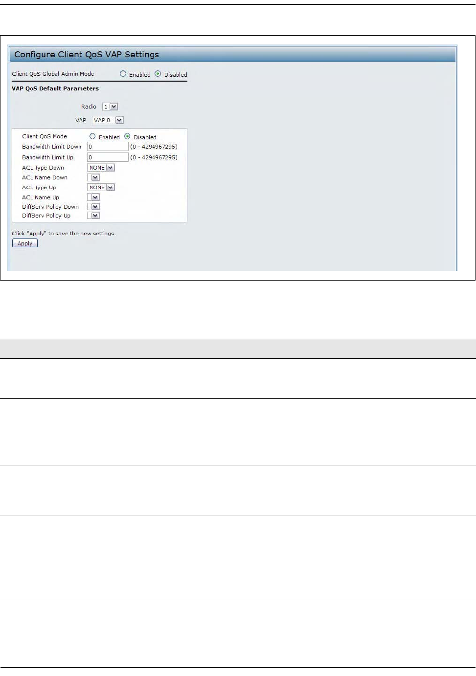
ConfiguringVAPQoSParameters
D-Link UnifiedAccessPointAdministrator’sGuide
November2011 Page129
UnifiedAccessPointAdministrator’sGuide
Figure40:VAPQoSParameters
Table52:VAPQoSParameters
Field Description
ClientQoSGlobalAdmin
Mode
EnableordisableClientQoSoperationontheAP.
ChangingthissettingwillnotaffecttheWMMsettingsyouconfigureonthe
QoSpage.
Radio Fordual‐radioAPs,selectRadio1orRadio2tospecifywhichradioto
configure.
VAP SpecifytheVAPthatwillhavetheClientQoSsettingsthatyouconfigure.
TheQoSsettingsyouconfigurefortheselectedVAPwillnotaffectclientsthat
accessthenetworkthroughotherVAPs.
ClientQoSMode EnableordisableQoSoperationontheVAPselectedintheVAPmenu.
QoSmustbeenabledglobally(fromtheClientQoSGlobalAdminModefield)
andontheVAP(QoSModefield)fortheClientQoSsettingstobeappliedto
wirelessclients.
BandwidthLimitDown EnterthemaximumallowedtransmissionratefromtheAPtothewireless
clientinbitspersecond.Thevalidrangeis0–429496000bits/sec.
Thevalueyouentermustbeamultipleof8000bits/sec,inotherwords,the
valuemustben×8000bits/sec,wheren=0,1,2,3...Ifyouattempttosetthe
limittoavaluethatisnotamultipleof8000bits/sec,theconfigurationwillbe
rejected.Avalueof0meansthatthebandwidthmaximumlimitisnotenforced
inthisdirection.
ConfiguringVAPQoSParameters
D-Link UnifiedAccessPointAdministrator’sGuide
November2011 Page130
UnifiedAccessPointAdministrator’sGuide
BandwidthLimitUp EnterthemaximumallowedclienttransmissionratetotheAPinbitsper
second.Thevalidrangeis0–4294967295bps.
Thevalueyouentermustben×8000bits/sec,wheren=0,1,2,3...Ifyou
attempttosetthelimittoavaluethatisnotamultipleof8000bits/sec,the
configurationwillberejected.Avalueof0meansthatthebandwidth
maximumlimitisnotenforcedinthisdirection.
ACLTypeDown SelectthetypeofACLtoapplytotrafficintheoutbound(down)direction,
whichcanbeoneofthefollowing:
•IPv4:TheACLexaminesIPv4packetsformatchestoACLrules
•IPv6:TheACLexaminesIPv6packetsformatchestoACLrules
•MAC:TheACLexamineslayer2framesformatchestoACLrules
ACLNameDown SelectthenameoftheACLappliedtotrafficintheoutbound(down)direction.
Afterswitchingthepacketorframetotheoutboundinterface,theACL'srules
arecheckedforamatch.Thepacketorframeistransmittedifitispermitted,
anddiscardedifitisdenied.
ACLTypeUp SelectthetypeofACLtoapplytotrafficintheinbound(up)direction,which
canbeoneofthefollowing:
•IPv4:TheACLexaminesIPv4packetsformatchestoACLrules
•IPv6:TheACLexaminesIPv6packetsformatchestoACLrules
•MAC:TheACLexamineslayer2framesformatchestoACLrules
ACLNameUp SelectthenameoftheACLappliedtotrafficenteringtheAPintheinbound
(up)direction.
WhenapacketorframeisreceivedbytheAP,theACL'srulesarecheckedfora
match.Thepacketorframeisprocessedifitispermitted,anddiscardedifitis
denied.
DiffServPolicyDown SelectthenameoftheDiffServpolicyappliedtotrafficfromtheAPinthe
outbound(down)direction.
DiffServPolicyUp SelectthenameoftheDiffServpolicyappliedtotrafficsenttotheAPinthe
inbound(up)direction.
Table52:VAPQoSParameters
Field Description

ManagingClientQoSACLs
D-Link UnifiedAccessPointAdministrator’sGuide
November2011 Page131
UnifiedAccessPointAdministrator’sGuide
ManagingClientQoSACLs
ACLsareacollectionofpermitanddenyconditions,calledrules,thatprovidesecuritybyblockingunauthorized
usersandallowingauthorizeduserstoaccessspecificresources.ACLscanblockanyunwarrantedattemptsto
reachnetworkresources.
TheUAPsupportsupto50IPv4,IPv6,andMACACLs.
IPv4andIPv6ACLs
IPACLsclassifytrafficforLayers3and4.
EachACLisasetofupto10rulesappliedtotrafficsentfromawirelessclientortobereceivedbyawireless
client.Eachrulespecifieswhetherthecontentsofagivenfieldshouldbeusedtopermitordenyaccesstothe
network.Rulescanbebasedonvariouscriteriaandmayapplytooneoremorefieldswithinapacket,suchas
thesourceordestinationIPaddress,thesourceordestinationL4port,ortheprotocolcarriedinthepacket.
MACACLs
MACACLsareLayer2ACLs.Youcanconfiguretherulestoinspectfieldsofaframesuchasthesourceor
destinationMACaddress,theVLANID,ortheClassofService802.1ppriority.Whenaframeentersorexitsthe
APport(dependingonwhethertheACLisappliedintheupordowndirection),theAPinspectstheframeand
checkstheACLrulesagainstthecontentoftheframe.Ifanyoftherulesmatchthecontent,apermitordeny
actionistakenontheframe.
ACLConfigurationProcess
ConfigureACLsandrulesontheClientQoSACLpage(steps1–5),andthenapplytherulestoaspecifiedVAP
ontheAPQoSParameterspage(step6).
UsethefollowinggeneralstepstoconfigureACLs:
1. SpecifyanamefortheACL.
2. SelectthetypeofACLtoadd.
3. AddtheACL
4. AddnewrulestotheACL.
5. Configurethematchcriteriafortherules.
6. ApplytheACLtooneormoreVAPs.
ForanexampleofhowtoconfigureanACL,see“ACLConfiguration”onpage174
ToconfigureanACL,clicktheClientQoSACLtab.
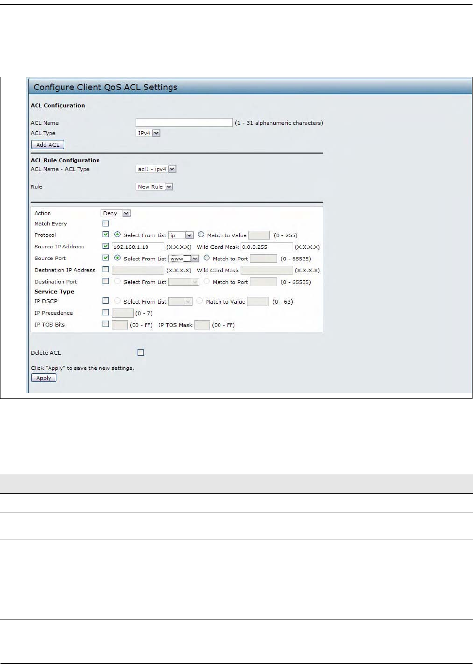
ManagingClientQoSACLs
D-Link UnifiedAccessPointAdministrator’sGuide
November2011 Page132
UnifiedAccessPointAdministrator’sGuide
ThefieldstoconfigureACLrulesappearonlyafteryouhavecreatedanACL.Thefollowingimageshowsthe
configurationofanewrulefortheIPv4ACLnamedacl1.TherulepreventsHTTPtrafficfromallclientsinthe
192.168.20.0networkfrombeingforwarded.
Figure41:ClientQoSACL
ThefollowingtabledescribesthefieldsavailableontheClientQoSACLpage.
Table53:ACLConfiguration
Field Description
ACLConfiguration
ACLName EnteranametoidentifytheACL.Thenamecancontainfrom1–31alphanumeric
characters.Spacesarenotallowed.
ACLType SelectthetypeofACLtoconfigure:
•IPv4
•IPv6
•MAC
IPv4andIPv6ACLscontrolaccesstonetworkresourcesbasedonLayer3andLayer
4criteria.MACACLscontrolaccessbasedonLayer2criteria.

ManagingClientQoSACLs
D-Link UnifiedAccessPointAdministrator’sGuide
November2011 Page133
UnifiedAccessPointAdministrator’sGuide
ACLRuleConfiguration
ACLName‐ACLType SelecttheACLtoconfigurewiththenewrule.ThelistcontainsallACLsaddedinthe
ACLConfigurationsection.
Rule ToconfigureanewruletoaddtotheselectedACL,selectNewRule.Toaddan
existingruletoanACLortomodifyarule,selecttherulenumber.
WhenanACLhasmultiplerules,therulesareappliedtothepacketorframeinthe
orderinwhichyouaddthemtotheACL.Thereisanimplicitdenyallruleasthefinal
rule.
Action SpecifieswhethertheACLrulepermitsordeniesanaction.
•WhenyouselectPermit,theruleallowsalltrafficthatmeetstherulecriteriato
enterorexittheAP(dependingontheACLdirectionyouselect).Trafficthat
doesnotmeetthecriteriaisdropped.
•WhenyouselectDeny,theruleblocksalltrafficthatmeetstherulecriteriafrom
enteringorexitingtheAP(dependingontheACLdirectionyouselect).Traffic
thatdoesnotmeetthecriteriaisforwardedunlessthisruleisthefinalrule.
BecausethereisanimplicitdenyallruleattheendofeveryACL,trafficthatis
notexplicitlypermittedisdropped.
MatchEvery Indicatesthattherule,whicheitherhasapermitordenyaction,willmatchthe
frameorpacketregardlessofitscontents.
Ifyouselectthisfield,youcannotconfigureanyadditionalmatchcriteria.The
MatchEveryoptionisselectedbydefaultforanewrule.Youmustcleartheoption
toconfigureothermatchfields.
IPv4ACL
Protocol SelecttheProtocolfieldtouseanL3orL4protocolmatchconditionbasedonthe
valueoftheIPProtocolfieldinIPv4packetsortheNextHeaderfieldofIPv6packets.
Onceyouselectthefield,choosetheprotocoltomatchbykeywordorentera
protocolID.
SelectFromList
Selectoneofthefollowingprotocolsfromthelist:
•IP
•ICMP
•IGMP
•TCP
•UDP
MatchtoValue
Tomatchaprotocolthatisnotlistedbyname,entertheprotocolID.
TheprotocolIDisastandardvalueassignedbytheIANA.Therangeisanumber
from0–255.
SourceIPAddress Selectthisfieldtorequireapacket'ssourceIPaddresstomatchtheaddresslisted
here.EnteranIPaddressintheappropriatefieldtoapplythiscriteria.
Table53:ACLConfiguration(Cont.)
Field Description

ManagingClientQoSACLs
D-Link UnifiedAccessPointAdministrator’sGuide
November2011 Page134
UnifiedAccessPointAdministrator’sGuide
WildCardMask SpecifiesthesourceIPaddresswildcardmask.
Thewildcardmasksdetermineswhichbitsareusedandwhichbitsareignored.A
wildcardmaskof255.255.255.255indicatesthatnobitisimportant.Awildcardof
0.0.0.0indicatesthatallofthebitsareimportant.ThisfieldisrequiredwhenSource
IPAddressischecked.
Awildcardmaskis,inessence,theinverseofasubnetmask.Forexample,Tomatch
thecriteriatoasinglehostaddress,useawildcardmaskof0.0.0.0.Tomatchthe
criteriatoa24‐bitsubnet(forexample192.168.10.0/24),useawildcardmaskof
0.0.0.255.
SourcePort Selectthisfieldtoincludeasourceportinthematchconditionfortherule.The
sourceportisidentifiedinthedatagramheader.
Onceyouselectthefield,choosetheportnameorentertheportnumber.
SelectFromList
Selectthekeywordassociatedwiththesourceporttomatch:
•ftp
• ftpdata
•http
•smtp
•snmp
•telnet
•tftp
•www
Eachofthesekeywordstranslatesintoitsequivalentportnumber.
MatchtoPort
EntertheIANAportnumbertomatchtothesourceportidentifiedinthedatagram
header.Theportrangeis0–65535andincludesthreedifferenttypesofports:
•0–1023:WellKnownPorts
• 1024–49151:RegisteredPorts
• 49152–65535:Dynamicand/orPrivatePorts
DestinationIPAddress Selectthisfieldtorequireapacket'sdestinationIPaddresstomatchtheaddress
listedhere.EnteranIPaddressintheappropriatefieldtoapplythiscriteria.
WildCardMask SpecifiesthedestinationIPaddresswildcardmask.
Thewildcardmasksdetermineswhichbitsareusedandwhichbitsareignored.A
wildcardmaskof255.255.255.255indicatesthatnobitisimportant.Awildcardof
0.0.0.0indicatesthatallofthebitsareimportant.ThisfieldisrequiredwhenSource
IPAddressischecked.
Awildcardmaskisinessencetheinverseofasubnetmask.Forexample,Tomatch
thecriteriatoasinglehostaddress,useawildcardmaskof0.0.0.0.Tomatchthe
criteriatoa24‐bitsubnet(forexample192.168.10.0/24),useawildcardmaskof
0.0.0.255.
Table53:ACLConfiguration(Cont.)
Field Description

ManagingClientQoSACLs
D-Link UnifiedAccessPointAdministrator’sGuide
November2011 Page135
UnifiedAccessPointAdministrator’sGuide
DestinationPort Selectthisfieldtoincludeadestinationportinthematchconditionfortherule.The
destinationportisidentifiedinthedatagramheader.
Onceyouselectthefield,choosetheportnameorentertheportnumber.
SelectFromList
Selectthekeywordassociatedwiththedestinationporttomatch:
•ftp
•ftpdata
•http
•smtp
•snmp
•telnet
•tftp
•www
Eachofthesekeywordstranslatesintoitsequivalentportnumber.
MatchtoPort
EntertheIANAportnumbertomatchtothedestinationportidentifiedinthe
datagramheader.Theportrangeis0–65535andincludesthreedifferenttypesof
ports:
•0–1023:WellKnownPorts
• 1024–49151:RegisteredPorts
• 49152–65535:Dynamicand/orPrivatePorts
IPDSCP TouseIPDSCPasamatchcriteria,selectthecheckboxandselectaDSCPvalue
keywordorenteraDSCPvaluetomatch.Youcanselectonlyoneservicetype(DSCP,
IPPrecedenceorTOSbits)touseformatchcriteria.
SelectfromList
SelectfromalistofDSCPtypes.
MatchtoValue
EnteraDSCPValuetomatch(0–63).
IPPrecedence Selectthisoptionandenteravaluetousethepacket'sIPPrecedencevalueinthe
IPheaderasmatchcriteria.Youcanselectonlyoneservicetype(DSCP,IP
PrecedenceorTOSbits)touseformatchcriteria.
TheIPPrecedencerangeis0–7.
IPTOSBits Selectthisoptionandenteravaluetousethepacket'sTypeofServicebitsintheIP
headerasmatchcriteria.Youcanselectonlyoneservicetype(DSCP,IPPrecedence
orTOSbits)touseformatchcriteria.
TheIPTOSfieldinapacketisdefinedasalleightbitsoftheServiceTypeoctetin
theIPheader.TheTOSBitsvalueisatwo‐digithexadecimalnumberfrom00toff.
Thehigh‐orderthreebitsrepresenttheIPprecedencevalue.Thehigh‐ordersixbits
representtheIPDifferentiatedServicesCodePoint(DSCP)value.
Table53:ACLConfiguration(Cont.)
Field Description
ManagingClientQoSACLs
D-Link UnifiedAccessPointAdministrator’sGuide
November2011 Page136
UnifiedAccessPointAdministrator’sGuide
IPTOSMask EnteranIPTOSmaskvaluetoidentifythebitpositionsintheTOSBitsvaluethatare
usedforcomparisonagainsttheIPTOSfieldinapacket.
TheTOSMaskvalueisatwo‐digithexadecimalnumberfrom00toff,representing
aninverted(i.e.wildcard)mask.Thezero‐valuedbitsintheTOSMaskdenotethe
bitpositionsintheTOSBitsvaluethatareusedforcomparisonagainsttheIPTOS
fieldofapacket.Forexample,tocheckforanIPTOSvaluehavingbits7and5set
andbit1clear,wherebit7ismostsignificant,useaTOSBitsvalueofa0andaTOS
Maskof00.Thisisanoptionalconfiguration.
IPv6ACL
Protocol SelecttheProtocolfieldtouseanL3orL4protocolmatchconditionbasedonthe
valueoftheIPProtocolfieldinIPv4packetsortheNextHeaderfieldofIPv6packets.
Onceyouselectthefield,choosetheprotocoltomatchbykeywordorprotocolID.
SourceIPv6Address Selectthisfieldtorequireapacket'ssourceIPv6addresstomatchtheaddresslisted
here.EnteranIPv6addressintheappropriatefieldtoapplythiscriteria.
SourceIPv6PrefixLength EntertheprefixlengthofthesourceIPv6address.
SourcePort Selectthisoptiontoincludeasourceportinthematchconditionfortherule.The
sourceportisidentifiedinthedatagramheader.
Onceyouselecttheoption,choosetheportnameorentertheportnumber.
DestinationIPv6Address Selectthisfieldtorequireapacket'sdestinationIPv6addresstomatchtheaddress
listedhere.EnteranIPv6addressintheappropriatefieldtoapplythiscriteria.
DestinationIPv6Prefix
Length
EntertheprefixlengthofthedestinationIPv6address.
DestinationPort Selectthisoptiontoincludeadestinationportinthematchconditionfortherule.
Thedestinationportisidentifiedinthedatagramheader.
Onceyouselecttheoption,choosetheportnameorentertheportnumber.
IPv6FlowLabel Flowlabelis20‐bitnumberthatisuniquetoanIPv6packet.Itisusedbyend
stationstosignifyquality‐of‐servicehandlinginrouters(range0to1048575).
IPv6DSCP TouseIPv6DSCPasamatchcriteria,selectthecheckboxandselectaDSCPvalue
keywordorenteraDSCPvaluetomatch.Youcanselectonlyoneservicetype(DSCP,
IPPrecedenceorTOSbits)touseformatchcriteria.
SelectfromList
SelectfromalistofDSCPtypes.
MatchtoValue
EnteraDSCPValuetomatch(0–63).
Table53:ACLConfiguration(Cont.)
Field Description
ManagingClientQoSACLs
D-Link UnifiedAccessPointAdministrator’sGuide
November2011 Page137
UnifiedAccessPointAdministrator’sGuide
Afteryousetthedesiredrulecriteria,clickApply.TodeleteanACL,selecttheDeleteACLoptionandclick
Apply.
MACACL
EtherType SelecttheEtherTypefieldtocomparethematchcriteriaagainstthevalueinthe
headerofanEthernetframe.
SelectanEtherTypekeywordorenteranEtherTypevaluetospecifythematch
criteria.
SelectfromListSelect
Selectoneofthefollowingprotocoltypes:
• appletalk
•arp
•ipv4
•ipv6
•ipx
•netbios
• pppoe
MatchtoValue
Enteracustomprotocolidentifiertowhichpacketsarematched.Thevalueisafour‐
digithexidecimalnumberintherangeof0600–FFFF.
ClassofService Selectthisfieldandenteran802.1puserprioritytocompareagainstanEthernet
frame.
Thevalidrangeis0–7.Thisfieldislocatedinthefirst/only802.1QVLANtag.
SourceMACAddress SelectthisfieldandenterthesourceMACaddresstocompareagainstanEthernet
frame.
SourceMACMask SelectthisfieldandenterthesourceMACaddressmaskspecifyingwhichbitsinthe
sourceMACtocompareagainstanEthernetframe.
A0indicatesthattheaddressbitissignificant,andanfindicatesthattheaddress
bitistobeignored.AMACmaskof00:00:00:00:00:00matchesasingleMAC
address.
DestinationMAC
Address
SelectthisfieldandenterthedestinationMACaddresstocompareagainstan
Ethernetframe.
DestinationMACMask EnterthedestinationMACaddressmaskspecifyingwhichbitsinthedestination
MACtocompareagainstanEthernetframe.
A0indicatesthattheaddressbitissignificant,andanfindicatesthattheaddress
bitistobeignored.AMACmaskof00:00:00:00:00:00matchesasingleMAC
address.
VLANID SelectthisfieldandentertheVLANIDstocompareagainstanEthernetframe.
Thisfieldislocatedinthefirst/only802.1QVLANtag.
Table53:ACLConfiguration(Cont.)
Field Description

CreatingaDiffServClassMap
D-Link UnifiedAccessPointAdministrator’sGuide
November2011 Page138
UnifiedAccessPointAdministrator’sGuide
CreatingaDiffServClassMap
TheClientQoSfeaturecontainsDifferentiatedServices(DiffServ)supportthatallowstraffictobeclassifiedinto
streamsandgivencertainQoStreatmentinaccordancewithdefinedper‐hopbehaviors.
StandardIP‐basednetworksaredesignedtoprovidebesteffortdatadeliveryservice.Besteffortserviceimplies
thatthenetworkdeliversthedatainatimelyfashion,althoughthereisnoguaranteethatitwill.Duringtimes
ofcongestion,packetsmaybedelayed,sentsporadically,ordropped.FortypicalInternetapplications,suchas
e‐mailandfiletransfer,aslightdegradationinserviceisacceptableandinmanycasesunnoticeable.However,
onapplicationswithstricttimingrequirements,suchasvoiceormultimedia,anydegradationofservicehas
undesirableeffects.
Byclassifyingthetrafficandcreatingpoliciesthatdefinehowtohandlethesetrafficclasses,youcanmakesure
thattime‐sensitivetrafficisgivenprecedenceoverothertraffic.
TheUAPsupportsupto50ClassMaps.
DefiningDiffServ
TouseDiffServforClientQoS,usetheClassMapandPolicyMappagestodefinethefollowingcategoriesand
theircriteria:
•Class:createclassesanddefineclasscriteria
•Policy:createpolicies,associateclasseswithpolicies,anddefinepolicystatements
Onceyoudefinetheclassandassociateitwithapolicy,applythepolicytoaspecifiedVAPontheVAPQoS
Parameterspage.
Packetsareclassifiedandprocessedbasedondefinedcriteria.Theclassificationcriteriaisdefinedbyaclass.
Theprocessingisdefinedbyapolicy'sattributes.Policyattributesmaybedefinedonaper‐classinstancebasis,
anditistheseattributesthatareappliedwhenamatchoccurs.Apolicycancontainmultipleclasses.Whenthe
policyisactive,theactionstakendependonwhichclassmatchesthepacket.
Packetprocessingbeginsbytestingtheclassmatchcriteriaforapacket.Apolicyisappliedtoapacketwhena
classmatchwithinthatpolicyisfound.DiffServissupportedforIPv4andIPv6packets.
UsetheClassMappagetoaddanewDiffservclassname,ortorenameordeleteanexistingclass,anddefine
thecriteriatoassociatewiththeDiffServclass.
ToconfigureaDiffServClassMap,clicktheClassMaptab.
Note:TheClassMappagedisplaystheMatchCriteriaConfigurationfieldsonlyifaClassMaphasbeen
created.TocreateaClassMap,enteranameintheClassMapNamefieldandclickAddClassMap.
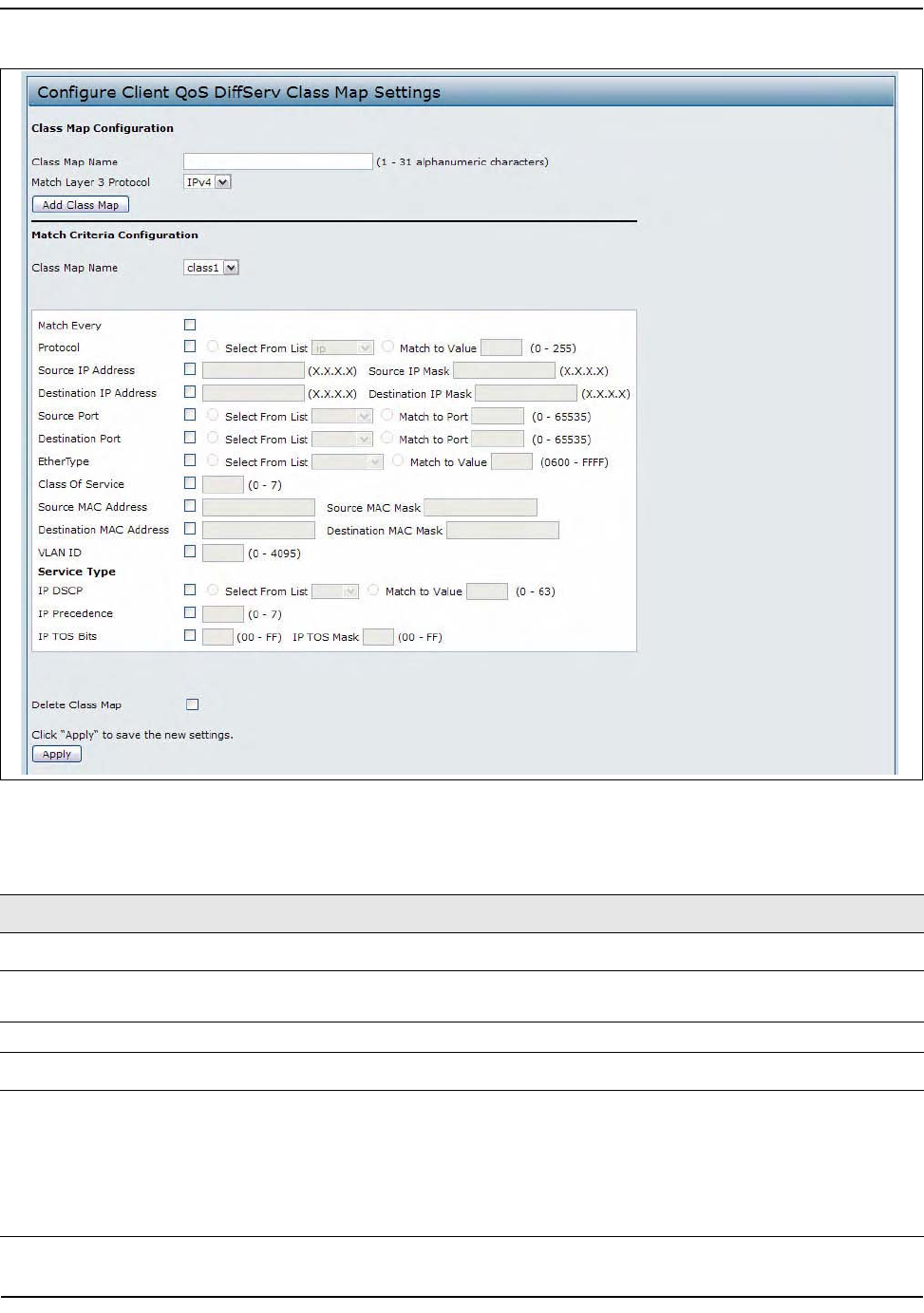
CreatingaDiffServClassMap
D-Link UnifiedAccessPointAdministrator’sGuide
November2011 Page139
UnifiedAccessPointAdministrator’sGuide
Figure42:ClientQoSDiffServClassMap
Table54:DiffServClassMap
Field Description
ClassMapConfiguration
ClassMapName EnteraClassMapNametoadd.Thenamecanrangefrom1to31
alphanumericcharacters.
MatchLayer3Protocol SpecifywhethertoclassifyIPv4orIPv6packets.
MatchCriteriaConfiguration
ClassMapName Selectnameoftheclasstoconfigure.
UsethefieldsintheMatchCriteriaConfigurationareatomatchpacketstoa
class.Selectthecheckboxforeachfieldtobeusedasacriterionforaclassand
enterdataintherelatedfield.Youcanhavemultiplematchcriteriainaclass.
Note:Thematchcriteriafieldsthatareavailabledependonwhethertheclass
mapisanIPv4orIPv6classmap.

CreatingaDiffServClassMap
D-Link UnifiedAccessPointAdministrator’sGuide
November2011 Page140
UnifiedAccessPointAdministrator’sGuide
MatchEvery SelectMatchEverytospecifythatthematchconditionistruetoallthe
parametersinanL3packet.
AllL3packetswillmatchanMatchEverymatchcondition.
Protocol SelecttheProtocolfieldtouseanL3orL4protocolmatchconditionbasedon
thevalueoftheIPProtocolfieldinIPv4packetsortheNextHeaderfieldofIPv6
packets.
Onceyouselectthefield,choosetheprotocoltomatchbykeywordorentera
protocolID.
SelectFromList
Selectoneofthefollowingprotocolsfromthelist:
•IP
•ICMP
•IPv6
•ICMPv6
•IGMP
•TCP
•UDP
MatchtoValue
Tomatchaprotocolthatisnotlistedbyname,entertheprotocolID.
TheprotocolIDisastandardvalueassignedbytheIANA.Therangeisanumber
from0–255.
IPv4ClassMaps
SourceIPAddress Selectthisfieldtorequireapacket'ssourceIPaddresstomatchtheaddress
listedhere.EnteranIPaddressintheappropriatefieldtoapplythiscriteria.
SourceIPMask EnterthesourceIPaddressmask.
ThemaskforDiffServisanetwork‐stylebitmaskinIPdotteddecimalformat
indicatingwhichpart(s)ofthedestinationIPAddresstouseformatching
againstpacketcontent.
ADiffServmaskof255.255.255.255indicatesthatallbitsareimportant,anda
maskof0.0.0.0indicatesthatnobitsareimportant.Theoppositeistruewith
anACLwildcardmask.Forexample,tomatchthecriteriatoasinglehost
address,useaDiffServmaskof255.255.255.255.Tomatchthecriteriatoa24‐
bitsubnet(forexample192.168.10.0/24),useamaskof255.255.255.0.
DestinationIPAddress Selectthisfieldtorequireapacket'sdestinationIPaddresstomatchthe
addresslistedhere.EnteranIPaddressintheappropriatefieldtoapplythis
criteria.
DestinationIPMask EnterthedestinationIPaddressmask.
ThemaskforDiffServisanetwork‐stylebitmaskinIPdotteddecimalformat
indicatingwhichpart(s)ofthedestinationIPAddresstouseformatching
againstpacketcontent.
ADiffServmaskof255.255.255.255indicatesthatallbitsareimportant,anda
maskof0.0.0.0indicatesthatnobitsareimportant.Theoppositeistruewith
anACLwildcardmask.Forexample,tomatchthecriteriatoasinglehost
address,useaDiffServmaskof255.255.255.255.Tomatchthecriteriatoa24‐
bitsubnet(forexample192.168.10.0/24),useamaskof255.255.255.0.
Table54:DiffServClassMap(Cont.)
Field Description
CreatingaDiffServClassMap
D-Link UnifiedAccessPointAdministrator’sGuide
November2011 Page141
UnifiedAccessPointAdministrator’sGuide
IPv6ClassMaps
SourceIPv6Address Selectthisfieldtorequireapacket'ssourceIPv6addresstomatchtheaddress
listedhere.EnteranIPv6addressintheappropriatefieldtoapplythiscriteria.
SourceIPv6PrefixLength EntertheprefixlengthofthesourceIPv6address.
DestinationIPv6Address Selectthisfieldtorequireapacket'sdestinationIPv6addresstomatchthe
addresslistedhere.EnteranIPv6addressintheappropriatefieldtoapplythis
criteria.
DestinationIPv6Prefix
Length
EntertheprefixlengthofthedestinationIPv6address.
IPv6FlowLabelFlowlabelis20‐bitnumberthatisuniquetoanIPv6packet.Itisusedbyend
stationstosignifyquality‐of‐servicehandlinginrouters(range0to1048575).
IPDSCP TouseIPDSCPasamatchcriteria,selectthecheckboxandselectaDSCPvalue
keywordorenteraDSCP.
SelectfromList
SelectfromalistofDSCPtypes.
MatchtoValue
EnteraDSCPValuetomatch(0–63).
IPv4andIPv6ClassMaps
SourcePort Selectthisfieldtoincludeasourceportinthematchconditionfortherule.The
sourceportisidentifiedinthedatagramheader.
Onceyouselectthefield,choosetheportnameorentertheportnumber.
SelectFromList
Selectthekeywordassociatedwiththesourceporttomatch:
•ftp
• ftpdata
•http
•smtp
•snmp
•telnet
•tftp
•www
Eachofthesekeywordstranslatesintoitsequivalentportnumber.
MatchtoPort
EntertheIANAportnumbertomatchtothesourceportidentifiedinthe
datagramheader.Theportrangeis0–65535andincludesthreedifferenttypes
ofports:
•0–1023:WellKnownPorts
•1024–49151:RegisteredPorts
•49152–65535:Dynamicand/orPrivatePorts
Table54:DiffServClassMap(Cont.)
Field Description

CreatingaDiffServClassMap
D-Link UnifiedAccessPointAdministrator’sGuide
November2011 Page142
UnifiedAccessPointAdministrator’sGuide
DestinationPort Selectthisfieldtoincludeadestinationportinthematchconditionforthe
rule.Thedestinationportisidentifiedinthedatagramheader.
Onceyouselectthefield,choosetheportnameorentertheportnumber.
SelectFromList
Selectthekeywordassociatedwiththedestinationporttomatch:
•ftp
•ftpdata
•http
•smtp
•snmp
•telnet
•tftp
•www
Eachofthesekeywordstranslatesintoitsequivalentportnumber.
MatchtoPort
EntertheIANAportnumbertomatchtothedestinationportidentifiedinthe
datagramheader.Theportrangeis0–65535andincludesthreedifferenttypes
ofports:
•0–1023:WellKnownPorts
•1024–49151:RegisteredPorts
•49152–65535:Dynamicand/orPrivatePorts
EtherTypeSelecttheEtherTypefieldtocomparethematchcriteriaagainstthevaluein
theheaderofanEthernetframe.
SelectanEtherTypekeywordorenteranEtherTypevaluetospecifythematch
criteria.
SelectfromListSelect
Selectoneofthefollowingprotocoltypes:
• appletalk
•arp
•ipv4
•ipv6
•ipx
•netbios
• pppoe
MatchtoValue
Enteracustomprotocolidentifiertowhichpacketsarematched.Thevalueis
afour‐digithexidecimalnumberintherangeof0600–FFFF.
ClassofService Selectthefieldandenteraclassofservice802.1puserpriorityvaluetobe
matchedforthepackets.Thevalidrangeis0–7.
SourceMACAddress SelectthisfieldandenterthesourceMACaddresstocompareagainstan
Ethernetframe.
Table54:DiffServClassMap(Cont.)
Field Description
CreatingaDiffServClassMap
D-Link UnifiedAccessPointAdministrator’sGuide
November2011 Page143
UnifiedAccessPointAdministrator’sGuide
TodeleteaClassMap,selecttheDeleteClassMapoptionandclickApply.
SourceMACMask EnterthesourceMACaddressmaskspecifyingwhichbitsinthedestination
MACtocompareagainstanEthernetframe.
Anfindicatesthattheaddressbitissignificant,anda0indicatesthatthe
addressbitistobeignored.AMACmaskofff:ff:ff:ff:ff:ffmatchesasingleMAC
address.
DestinationMACAddress SelectthisfieldandenterthedestinationMACaddresstocompareagainstan
Ethernetframe.
DestinationMACMask EnterthedestinationMACaddressmaskspecifyingwhichbitsinthe
destinationMACtocompareagainstanEthernetframe.
Anfindicatesthattheaddressbitissignificant,anda0indicatesthatthe
addressbitistobeignored.AMACmaskofff:ff:ff:ff:ff:ffmatchesasingleMAC
address.
VLANID SelectthefieldandenteraVLANIDtobematchedforpackets.TheVLANID
rangeis0–4095.
IPv4ClassMaps
ServiceType Youcanspecifyonetypeofservicetouseinmatchingpacketstoclasscriteria.
IPDSCP TouseIPDSCPasamatchcriteria,selectthecheckboxandselectaDSCPvalue
keywordorenteraDSCP.
SelectfromList
SelectfromalistofDSCPtypes.
MatchtoValue
EnteraDSCPValuetomatch(0–63).
IPPrecedence Selectthisfieldtomatchthepacket'sIPPrecedencevaluetotheclasscriteria
IPPrecedencevalue.
TheIPPrecedencerangeis0–7.
IPTOSBits Selectthisfieldandenteravaluetousethepacket'sTypeofServicebitsinthe
IPheaderasmatchcriteria.
TheTOSbitvaluerangesbetween(00–FF).Thehigh‐orderthreebitsrepresent
theIPprecedencevalue.Thehigh‐ordersixbitsrepresenttheIPDifferentiated
ServicesCodePoint(DSCP)value.
IPTOSMask EnteranIPTOSmaskvaluetoperformabooleanANDwiththeTOSfieldinthe
headerofthepacketandcomparedagainsttheTOSenteredforthisrule.
TheTOSMaskcanbeusedtocomparespecificbits(Precedence/Typeof
Service)fromtheTOSfieldintheIPheaderofapacketagainsttheTOSvalue
enteredforthisrule.(00–FF).
DeleteClassMap ChecktodeletetheclassmapselectedintheClassMapNamemenu.Theclass
mapcannotbedeletedifitisalreadyattachedtoapolicy.
Table54:DiffServClassMap(Cont.)
Field Description
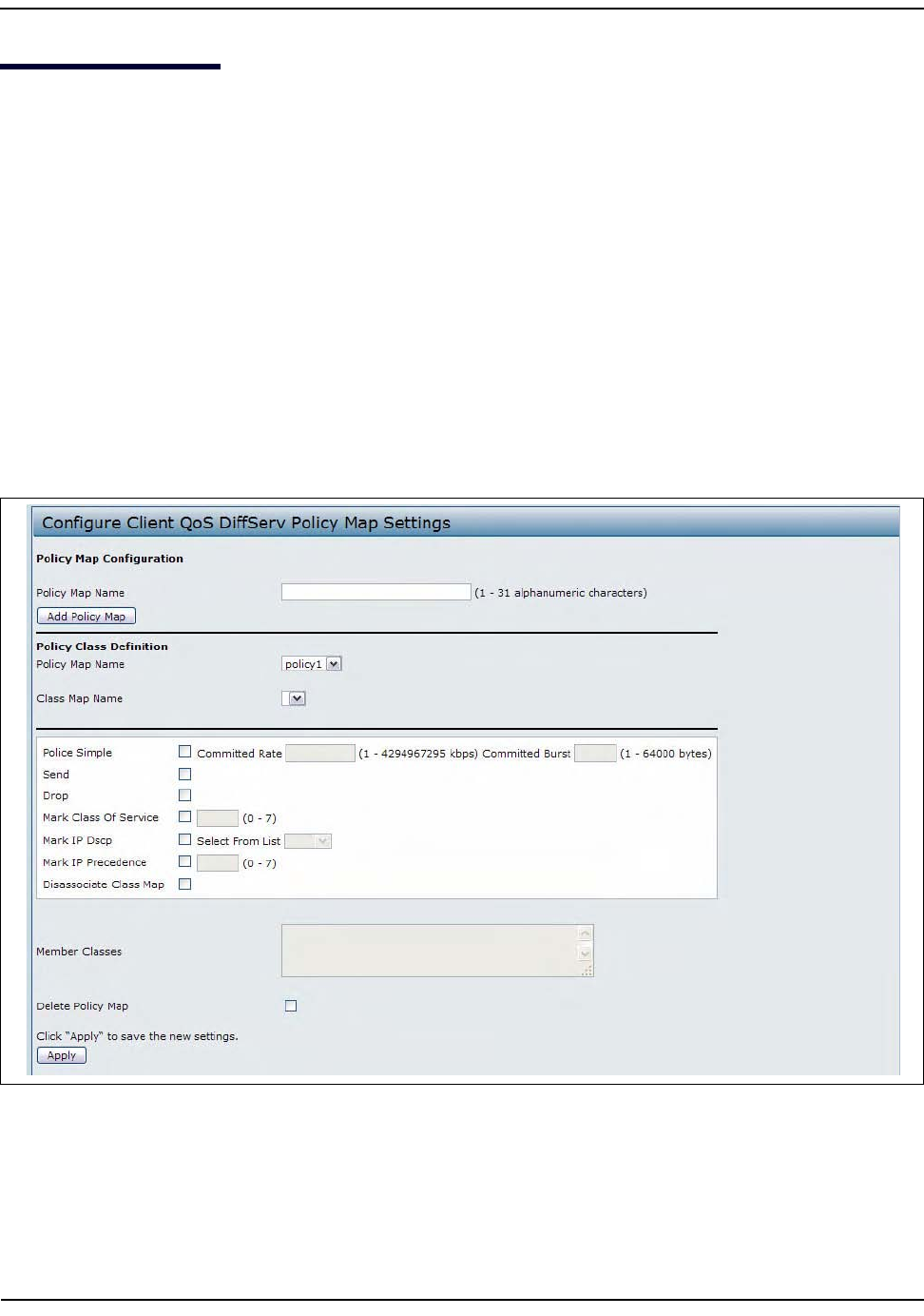
CreatingaDiffServPolicyMap
D-Link UnifiedAccessPointAdministrator’sGuide
November2011 Page144
UnifiedAccessPointAdministrator’sGuide
CreatingaDiffServPolicyMap
UsethePolicyMappagetocreateDiffServpoliciesandtoassociateacollectionofclasseswithoneormore
policystatements.
TheUAPsupportsupto50PolicyMaps.
Packetsareclassifiedandprocessedbasedondefinedcriteria.Theclassificationcriteriaisdefinedbyaclasson
theClassMappage.Theprocessingisdefinedbyapolicy'sattributesonthePolicyMappage.Policyattributes
maybedefinedonaper‐classinstancebasis,anditistheseattributesthatareappliedwhenamatchoccurs.
APolicyMapcancontainupto10ClassMaps.Whenthepolicyisactive,theactionstakendependonwhich
classmatchesthepacket.
Packetprocessingbeginsbytestingtheclassmatchcriteriaforapacket.Apolicyisappliedtoapacketwhena
classmatchwithinthatpolicyisfound.
TocreateaDiffServpolicy,clickthePolicyMaptab.
Figure43:ClientQoSDiffServPolicyMap
CreatingaDiffServPolicyMap
D-Link UnifiedAccessPointAdministrator’sGuide
November2011 Page145
UnifiedAccessPointAdministrator’sGuide
TodeleteaPolicyMap,selecttheDeletePolicyMapoptionandclickApply.
Table55:DiffServPolicyMap
Field Description
PolicyMapName Enterthennameofthepolicymaptoadd.Thenamecancontainupto31
alphanumericcharacters.
PolicyMapName(Policy
ClassDefinition)
Selectthepolicytoassociatewithamemberclass.
ClassMapName(PolicyClass
Definition)
Selectthememberclasstoassociatewiththispolicyname.
PoliceSimple Selectthisoptiontoestablishthetrafficpolicingstylefortheclass.Thesimple
formofthepolicingstyleusesasingledatarateandburstsize,resultingintwo
outcomes:conformandnonconform.
CommittedRate
Enterthecommittedrate,inKbps,towhichtrafficmustconform.
CommittedBurst
Enterthecommittedburstsize,inbytes,towhichtrafficmustconform.
Send SelectSendtospecifythatallpacketsfortheassociatedtrafficstreamareto
beforwardediftheclassmapcriteriaismet.
Drop SelectDroptospecifythatallpacketsfortheassociatedtrafficstreamareto
bedroppediftheclassmapcriteriaismet.
MarkClassofService Selectthisfieldtomarkallpacketsfortheassociatedtrafficstreamwiththe
specifiedclassofservicevalueinthepriorityfieldofthe802.1pheader.Ifthe
packetdoesnotalreadycontainthisheader,oneisinserted.TheCoSvalueis
anintegerfrom0–7.
MarkIPDSCP SelectthisfieldtomarkallpacketsfortheassociatedtrafficstreamwiththeIP
DSCPvalueyouselectfromthelistorspecify.
SelectfromList
SelectfromalistofDSCPtypes.
MatchtoValue
EnteraDSCPValuetomatch(0–63).
MarkIPPrecedence Selectthisfieldtomarkallpacketsfortheassociatedtrafficstreamwiththe
specifiedIPPrecedencevalue.TheIPPrecedencevalueisanintegerfrom0–7.
DisassociateClassMap SelectthisoptionandclickApplytoremovetheclassselectedintheClassMap
NamemenufromthepolicyselectedinthePolicyMapNamemenu.
MemberClasses ListsallDiffServclassescurrentlydefinedasmembersoftheselectedpolicy.If
noclassisassociatedwiththepolicy,thefieldisempty.
DeletePolicyMap SelectthisfieldtodeletethepolicymapshowinginthePolicyMapName
menu.
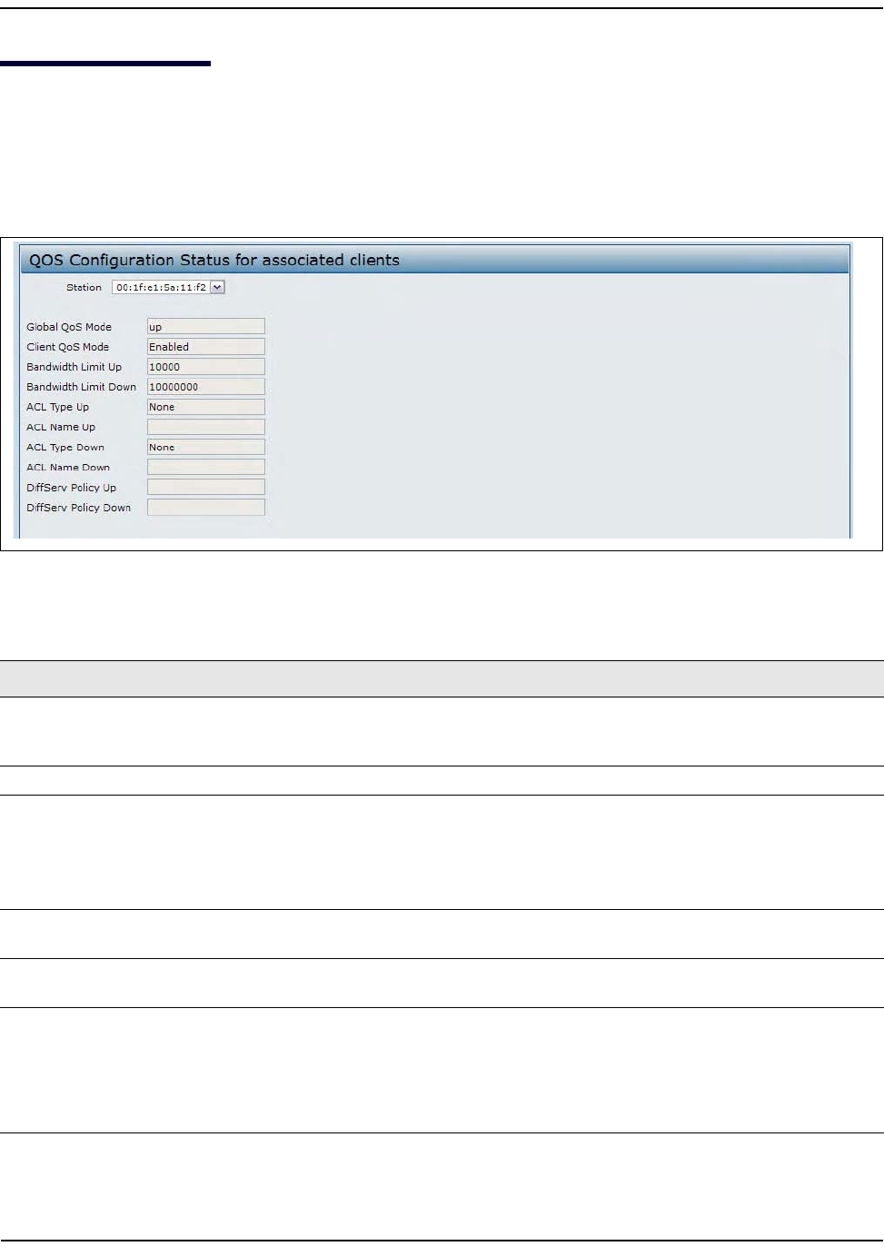
ClientQoSStatus
D-Link UnifiedAccessPointAdministrator’sGuide
November2011 Page146
UnifiedAccessPointAdministrator’sGuide
ClientQoSStatus
TheClientQoSStatuspageshowstheclientQoSsettingsthatareappliedtoeachclientcurrentlyassociated
withtheAP.
ToviewQoSsettingsforanassociatedclient,clicktheClientQoSStatustab.
Figure44:ClientQoSStatus
Table56:ClientQoSStatus
Field Description
Station TheStationmenucontainstheMACaddressofeachclientcurrentlyassociatedwith
theAP.ToviewtheQoSsettingsappliedtoaclient,selectitsMACaddressfromthe
list.
GlobalQoSMode ShowsthecurrentClientQoSGlobalAdminModeontheAP.
ClientQoSMode ShowswhethertheQOSmodefortheselectedclientisenabledordisabled.
Note:FortheQosModetobeenabledonaclient,itmustbegloballyenabledon
theAPandenabledontheVAPtheclientisassociatedwith.UsetheVAPQoS
ParameterspagetoenabletheQoSGlobalAdminmodeandtheper‐VAPQoS
Mode.
BandwidthLimitUp ShowsthemaximumallowedtransmissionratefromtheclienttotheAPinbitsper
second(bps).Thevalidrangeis0–4294967295bps.
BandwidthLimitDown ShowsthemaximumallowedtransmissionratefromtheAPtotheclientinbitsper
second(bps).Thevalidrangeis0–4294967295bps.
ACLTypeUp ShowsthetypeofACLthatisappliedtotrafficintheinbound(client‐to‐AP)
direction,whichcanbeoneofthefollowing:
•IPv4:TheACLexaminesIPv4packetsformatchestoACLrules.
•IPv6:TheACLexaminesIPv6packetsformatchestoACLrules.
•MAC:TheACLexamineslayer2framesformatchestoACLrules.
ConfiguringRADIUS‐AssignedClientQoSParameters
D-Link UnifiedAccessPointAdministrator’sGuide
November2011 Page147
UnifiedAccessPointAdministrator’sGuide
ConfiguringRADIUS‐AssignedClientQoSParameters
IfaVAPisconfiguredtouseWPAEnterprisesecurity,youcanincludeclientQoSinformationintheclient
databaseontheRADIUSserver.Whenaclientsuccessfullyauthenticates,theRADIUSservercaninclude
bandwidthlimitsandidentifytheACLsandDiffServpoliciestoapplytothespecificwirelessclient.ACLsand
DiffServpoliciesreferencedintheRADIUSclientdatabasemustmatchthenamesoftheACLsandDiffServ
policiesconfiguredontheAPtobesuccessfullyappliedtothewirelessclients.
Table57describestheQoSattributesthatcanbeincludedintheclient'sRADIUSserverentry.Ifawireless
clientsuccessfullyauthenticatesusingWPAEnterprise,eachQoSRADIUSattributethatexistsfortheclientis
senttotheAPforprocessing.Theattributesareoptionalanddonotneedtobepresentinthecliententry.If
theattributeisnotpresent,theClientQoSsettingontheAPisused.
ACLNameUp ShowsthenameoftheACLappliedtotrafficenteringtheAPintheinbound
direction.
WhenapacketorframeisreceivedbytheAP,theACL'srulesarecheckedfora
match.Thepacketorframeisprocessedifitispermittedanddiscardedifitis
denied.
ACLTypeDown ShowsthetypeofACLtoapplytotrafficintheoutbound(AP‐to‐client)direction,
whichcanbeoneofthefollowing:
•IPv4:TheACLexaminesIPv4packetsformatchestoACLrules.
•IPv6:TheACLexaminesIPv6packetsformatchestoACLrules
•MAC:TheACLexamineslayer2framesformatchestoACLrules
ACLNameDown ShowsthenameoftheACLappliedtotrafficintheoutbounddirection.
Afterswitchingthepacketorframetotheoutboundinterface,theACL'srulesare
checkedforamatch.Thepacketorframeistransmittedifitispermittedand
discardedifitisdenied.
DiffServPolicyUp ShowsthenameoftheDiffServpolicyappliedtotrafficsenttotheAPintheinbound
(client‐to‐AP)direction.
DiffServPolicyDown ShowsthenameoftheDiffServpolicyappliedtotrafficfromtheAPintheoutbound
(AP‐to‐client)direction.
Table57:ClientQoSRADIUSAttributes
RADIUSAttribute ID Description Type/Range
Vendor‐Specific(26),
WISPr‐Bandwidth‐
Max‐Down
14122,8 Maximumallowedclientreceptionratefrom
theAPinbitspersecond.Ifnonzero,the
specifiedvalueisroundeddowntothenearest
64KbpsvaluewhenusedintheAP(64Kbps
minimum).Ifzero,bandwidthlimitingisnot
enforcedfortheclientinthisdirection.
Type:integer
32‐bitunsignedinteger
value(0‐4294967295)
Table56:ClientQoSStatus(Cont.)
Field Description
ConfiguringRADIUS‐AssignedClientQoSParameters
D-Link UnifiedAccessPointAdministrator’sGuide
November2011 Page148
UnifiedAccessPointAdministrator’sGuide
Vendor‐Specific(26),
WISPr‐Bandwidth‐
Max‐Up
14122,7 Maximumallowedclienttransmissionrateto
theAPinbitspersecond.Ifnonzero,the
specifiedvalueisroundeddowntothenearest
64KbpsvaluewhenusedintheAP(64Kbps
minimum).Ifzero,bandwidthlimitingisnot
enforcedfortheclientinthisdirection.
Type:integer
32‐bitunsignedinteger
value(0‐4294967295)
Vendor‐Specific(26),
LVL7‐Wireless‐Client‐
ACL‐Dn
6132,120 Accesslistidentifiertobeappliedto802.1X
authenticatedwirelessclienttrafficinthe
outbound(down)direction.
IfthisattributereferstoanACLthatdoesnot
existontheAP,allpacketsforthisclientwillbe
droppeduntiltheACLisdefined.
Type:string
5‐36characters(notnull‐
terminated)
Thestringisoftheform
“type:name”where:type=
ACLtypeidentifier:IPV4,
IPV6,MAC
:=requiredseparator
character
name=1‐31alphanumeric
characters,specifyingthe
ACLnumber(IPV4)or
name(IPV6,MAC)
Vendor‐Specific(26),
LVL7‐Wireless‐Client‐
ACL‐Up
6132,121 Accesslistidentifiertobeappliedto802.1X
authenticatedwirelessclienttrafficinthe
inbound(up)direction.
IfthisattributereferstoanACLthatdoesnot
existontheAP,allpacketsforthisclientwillbe
droppeduntiltheACLisdefined.
Type:string
5‐36characters(notnull‐
terminated)Thestringisof
theform“type:name”
where:type=ACLtype
identifier:IPV4,IPV6,MAC
:=requiredseparator
character
name=1‐31alphanumeric
characters,specifyingthe
ACLnumber(IPV4)or
name(IPV6,MAC)
Vendor‐Specific(26),
LVL7‐Wireless‐Client‐
Policy‐Dn
6132,122 NameofDiffServpolicytobeappliedto802.1X
authenticatedwirelessclienttrafficinthe
outbound(down)direction.
Ifthisattributereferstoapolicynamethat
doesnotexistontheAP,allpacketsforthis
clientwillbedroppeduntiltheDiffServpolicyis
defined.
Type:string
1‐31characters(notnull‐
terminated)
Vendor‐Specific(26),
LVL7‐Wireless‐Client‐
Policy‐Up
6132,123 NameofDiffServpolicytobeappliedto802.1X
authenticatedwirelessclienttrafficinthe
inbound(up)direction.
Ifthisattributereferstoapolicynamethat
doesnotexistontheAP,allpacketsforthis
clientwillbedroppeduntiltheDiffServpolicyis
defined.
Type:string
1‐31characters(notnull‐
terminated)
Table57:ClientQoSRADIUSAttributes(Cont.)
RADIUSAttribute ID Description Type/Range

ClusteringMultipleAPs
D-Link UnifiedAccessPointAdministrator’sGuide
November2011 Page149
UnifiedAccessPointAdministrator’sGuide
Section9:ClusteringMultipleAPs
TheUAPsupportsAPclusters.Aclusterprovidesasinglepointofadministrationandletsyouview,deploy,
configure,andsecurethewirelessnetworkasasingleentityratherthanaseriesofseparatewirelessdevices.
ManagingAccessPointsintheCluster
TheAPclusterisadynamic,configuration‐awaregroupofAPsinthesamesubnetofanetwork.Eachcluster
canhaveupto16members.Onlyoneclusterperwirelessnetworkissupported;however,anetworksubnet
canhavemultipleclusters.Clusterscansharevariousconfigurationinformation,suchasVAPsettingsandQoS
queueparameters.
AclustercanbeformedbetweentwoAPsifthefollowingconditionsaremet:
•TheAPsusethesameradiomode(forexample,radio1uses802.11g)
•TheAPsareconnectedonthesamebridgedsegment.
•TheAPsjoiningtheclusterhavethesameClusterName.
• ClusteringmodeisenabledonbothAPs.
ClusteringSingleandDualRadioAPs
Clusteringofsingle‐anddual‐radiosisnotsupported.AclustercancontainamixifDWL‐6600APand
DWL‐8600APaccesspoints,butthisclustershouldnotcontainanyDWL‐3600APs.
ViewingandConfiguringClusterMembers
TheAccessPointspageallowsyoutostartorstopclusteringonanAP,viewtheclustermembers,andconfigure
thelocationandclusternameforaclustermember.FromtheAccessPointspage,youcanalsoclicktheIP
addressofeachclustermembertonavigatetoconfigurationsettingsanddataonanaccesspointinthecluster.
Toviewinformationaboutclustermembersandtoconfigurethelocationandclusterofanindividualmember,
clicktheAccessPointstab.
Note:FortwoAPstobeinthesamecluster,theydonotneedtohavethesamenumberofradios;
however,thesupportedcapabilitiesoftheradiosshouldbesame.
Note:Theweb‐basedUIimagesinthissectionshowtheDWL‐8600APadministrationpages.Pages
fortheDWL‐3600APwillnotdisplayinformationforRadio2becauseithasonlyoneradio.
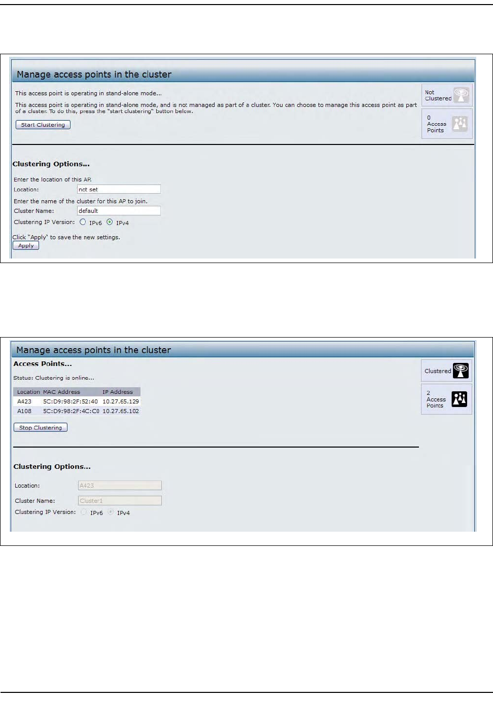
ManagingAccessPointsintheCluster
D-Link UnifiedAccessPointAdministrator’sGuide
November2011 Page150
UnifiedAccessPointAdministrator’sGuide
ThefollowingfigureshowstheCluster>AccessPointspagewhenclusteringisnotenabled.
Figure45:ClusterInformationandMemberConfiguration
ThefollowingfigureshowstheCluster>AccessPointspagewhenclusteringisenabledandtwoaccesspoints
areinthecluster.
Figure46:ClusterInformationandMemberConfiguration
IfclusteringiscurrentlydisabledontheAP,theStartClusteringbuttonisvisible.Ifclusteringisenabled,the
StopClusteringbuttonisvisible.Youcanedittheclusteringoptioninformationwhenclusteringisdisabled.
ManagingAccessPointsintheCluster
D-Link UnifiedAccessPointAdministrator’sGuide
November2011 Page151
UnifiedAccessPointAdministrator’sGuide
ThefollowingtabledescribestheconfigurationandstatusinformationavailableontheclusterAccessPoints
page.
Thefollowingtabledescribestheclusterinformationtoconfigureforanindividualmember.Theclustering
optionsareread‐onlywhenclusteringisenabled.Toconfiguretheclusteringoptions,youmuststopclustering.
RemovinganAccessPointfromtheCluster
Toremoveanaccesspointfromthecluster,dothefollowing.
1. GototheAdministrationWebpagesfortheclusteredaccesspoint.
TheAdministrationWebpagesforthestandaloneaccesspointaredisplayed.
2. ClicktheCluster>AccessPointslinkintheAdministrationpages.
3. ClickStopClustering.
ThechangewillbereflectedunderStatusforthataccesspoint;theaccesspointwillnowshowas
stand‐alone(insteadofcluster).
Table58:AccessPointsintheCluster
Field Description
Status Ifthestatusfieldisvisible,thentheAPisenabledforclustering.Ifclusteringisnotenabled,
thentheAPisoperatinginstand‐alonemodeandnoneoftheinformationinthistableis
visible.
TodisableclusteringontheAP,clickStopClustering.
Location Descriptionofwheretheaccesspointisphysicallylocated.
MACAddress MediaAccessControl(MAC)addressoftheaccesspoint.
TheaddressshownhereistheMACaddressforthebridge(br0).Thisistheaddressby
whichtheAPisknownexternallytoothernetworks.
IPAddress SpecifiestheIPaddressfortheaccesspoint.
EachIPaddressisalinktotheAdministrationWebpagesforthataccesspoint.Youcanuse
thelinkstonavigatetotheAdministrationWebpagesforaspecificaccesspoint.Thisis
usefulforviewingdataonaspecificaccesspointtomakesureaclustermemberispicking
upclusterconfigurationchanges,toconfigureadvancedsettingsonaparticularaccess
point,ortoswitchastandaloneaccesspointtoclustermode.
Table59:ClusteringOptions
Field Description
Location Enteradescriptionofwheretheaccesspointisphysicallylocated.
ClusterName EnterthenameoftheclusterfortheAPtojoin.
TheclusternameisnotsenttootherAPsinthecluster.Youmustconfigurethesame
clusternameoneachAPthatisamemberofthecluster.Theclusternamemustbe
uniqueforeachclusteryouconfigureonthenetwork.
ClusteringIPVersion SpecifytheIPversionthattheAPsintheclusterusetocommunicatewitheach
other.

ManagingAccessPointsintheCluster
D-Link UnifiedAccessPointAdministrator’sGuide
November2011 Page152
UnifiedAccessPointAdministrator’sGuide
AddinganAccessPointtoaCluster
Toaddanaccesspointthatiscurrentlyinstandalonemodebackintoacluster,dothefollowing.
1. GototheAdministrationWebpagesforthestandaloneaccesspoint.
2. ClicktheCluster>AccessPointslinkintheAdministrationpagesforthestand‐aloneaccesspoint.
TheAccessPoints pageforastandaloneaccesspointindicatesthatthecurrentmodeisstandalone.
3. TypethenameorlocationoftheAPintheLocationfieldtoidentifytheAPwithinthecluster.
4. TypethenameoftheclusterfortheAPtojoinintheClusterNamefield.
5. ClickStartClustering.
Theaccesspointisnowaclustermember.ItsStatus(Mode)ontheCluster>AccessPointspagenow
indicatesClusterinsteadofNotClustered.
NavigatingtoConfigurationInformationforaSpecificAP
Ingeneral,theUAPisdesignedforcentralmanagementofclusteredaccesspoints.Foraccesspointsinacluster,
allaccesspointsintheclusterreflectthesameconfiguration.Inthiscase,itdoesnotmatterwhichaccesspoint
youactuallyconnecttoforadministration.
Theremaybesituations,however,whenyouwanttoviewormanageinformationonaparticularaccesspoint.
Forexample,youmightwanttocheckstatusinformationsuchasclientassociationsoreventsforanaccess
point.Inthiscase,youcannavigatetotheAdministrationWebinterfaceforindividualaccesspointsbyclicking
theIPaddresslinksontheAccessPointspage.
AllclusteredaccesspointsareshownontheCluster>AccessPointspage.Tonavigatetoclusteredaccess
points,youcansimplyclickontheIPaddressforaspecificclustermembershowninthelist.
NavigatingtoanAPbyUsingitsIPAddressinaURL
YoucanalsolinktotheAdministrationWebpagesofaspecificaccesspoint,byenteringtheIPaddressforthat
accesspointasaURLdirectlyintoaWebbrowseraddressbarinthefollowingform:
http://IPAddressOfAccessPoint
whereIPAddressOfAccessPointistheaddressoftheparticularaccesspointyouwanttomonitororconfigure.
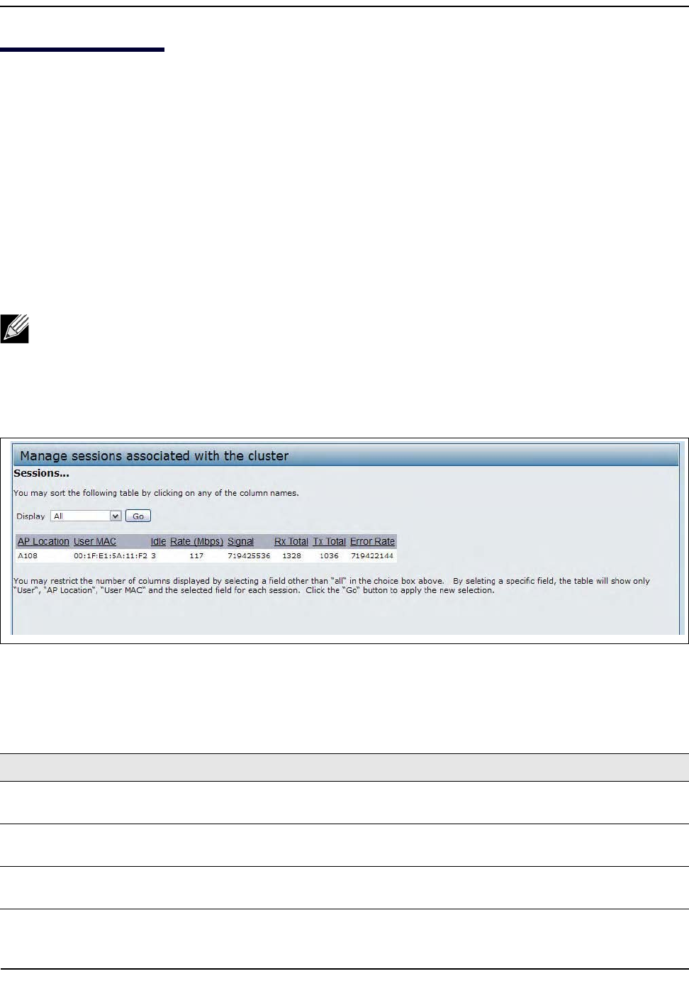
ManagingClusterSessions
D-Link UnifiedAccessPointAdministrator’sGuide
November2011 Page153
UnifiedAccessPointAdministrator’sGuide
ManagingClusterSessions
TheSessionspageshowsinformationaboutclientstationsassociatedwithaccesspointsinthecluster.Each
clientisidentifiedbyitsMACaddress,alongwiththeAP(location)towhichitiscurrentlyconnected.
Toviewaparticularstatisticforclientsessions,selectanitemfromtheDisplaydrop‐downlistandclickGo.You
canviewinformationaboutidletime,datarate,signalstrengthandsoon;allofwhicharedescribedindetail
inthetablebelow.
Asessioninthiscontextistheperiodoftimeinwhichauseronaclientdevice(station)withauniqueMAC
addressmaintainsaconnectionwiththewirelessnetwork.Thesessionbeginswhentheclientlogsontothe
network,andthesessionendswhentheclienteitherlogsoffintentionallyorlosestheconnectionforsome
otherreason.
Tomanagesessionsassociatedwiththecluster,clickCluster>Sessions.
Figure47:SessionManagement
Detailsaboutthesessioninformationshownisdescribedinthefollowingtable.
Note:Asessionisnotthesameasanassociation,whichdescribesaclientconnectiontoaparticular
accesspoint.AclientnetworkconnectioncanshiftfromoneclusteredAPtoanotherwithinthe
contextofthesamesession.AclientstationcanroambetweenAPsandmaintainthesession.
Table60:SessionManagement
Field Description
APLocation Indicatesthelocationoftheaccesspoint.
ThisisderivedfromthelocationdescriptionspecifiedontheBasicSettingspage.
UserMAC IndicatestheMACaddressofthewirelessclientdevice.
AMACaddressisahardwareaddressthatuniquelyidentifieseachnodeofanetwork.
Idle Indicatestheamountoftimethisstationhasremainedinactive.
Astationisconsideredtobeidlewhenitisnotreceivingortransmittingdata.
ConfiguringandViewingChannelManagementSettings
D-Link UnifiedAccessPointAdministrator’sGuide
November2011 Page154
UnifiedAccessPointAdministrator’sGuide
SortingSessionInformation
Tosorttheinformationshowninthetablesbyaparticularindicator,clickthecolumnlabelbywhichyouwant
toorderthings.Forexample,ifyouwanttoseethetablerowsorderedbysignalstrength,clicktheSignal
columnlabel.Theentrieswillbesortedbysignalstrength.
ConfiguringandViewingChannelManagementSettings
WhenChannelManagementisenabled,theUAPautomaticallyassignsradiochannelsusedbyclusteredaccess
points.Theautomaticchannelassignmentreducesmutualinterference(orinterferencewithotheraccess
pointsoutsideofitscluster)andmaximizesWi‐Fibandwidthtohelpmaintaintheefficiencyofcommunication
overthewirelessnetwork.
Youmuststartchannelmanagementtogetautomaticchannelassignments;itisdisabledbydefaultonanew
AP.
Ataspecifiedinterval,theChannelManagermapsAPstochanneluseandmeasuresinterferencelevelsinthe
cluster.Ifsignificantchannelinterferenceisdetected,theChannelManagerautomaticallyre‐assignssomeor
alloftheAPstonewchannelsperanefficiencyalgorithm(orautomatedchannelplan).IftheChannelManager
determinesthatachangeisnecessary,thatinformationissenttoallmembersoftheclusterandasyslog
messageisgeneratedindicatingthesenderAP,newandoldchannelassignments.
TheChannelManagementpageshowsprevious,current,andplannedchannelassignmentsforclustered
accesspoints.Bydefault,automaticchannelassignmentisdisabled.Youcanstartchannelmanagementto
optimizechannelusageacrosstheclusteronascheduledinterval.
Toconfigureandviewthechannelassignmentsfortheclustermembers,clicktheChannelManagementtab.
Rate Thespeedatwhichthisaccesspointistransferringdatatothespecifiedclient.
Thedatatransmissionrateismeasuredinmegabitspersecond(Mbps).
Thisvalueshouldfallwithintherangeoftheadvertisedratesetforthemodeinuseon
theaccesspoint.Forexample,6to54Mbpsfor802.11a.
Signal Indicatesthestrengthoftheradiofrequency(RF)signaltheclientreceivesfromthe
accesspoint.
ThemeasureusedforthisisavalueknownasReceivedSignalStrengthIndication(RSSI),
andwillbeavaluebetween0and100.
RSSIisdeterminedbyamechanismimplementedonthenetworkinterfacecard(NIC)of
theclientstation.
RxTotal Indicatesnumberoftotalpacketsreceivedbytheclientduringthecurrentsession.
TxTotal Indicatesnumberoftotalpacketstransmittedtotheclientduringthissession.
ErrorRate Indicatesthepercentageoftimeframesaredroppedduringtransmissiononthisaccess
point.
Table60:SessionManagement
Field Description
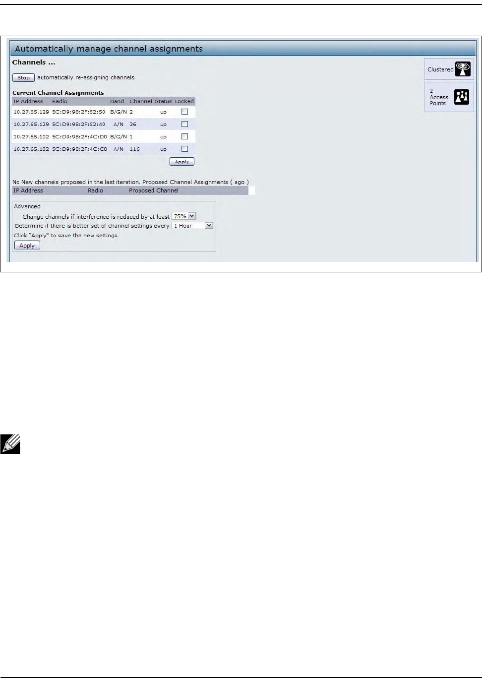
ConfiguringandViewingChannelManagementSettings
D-Link UnifiedAccessPointAdministrator’sGuide
November2011 Page155
UnifiedAccessPointAdministrator’sGuide
Figure48:ChannelManagement
Fromthispage,youcanviewchannelassignmentsforallAPsintheclusterandstoporstartautomaticchannel
management.ByusingtheAdvancedsettingsonthepage,youcanmodifytheinterferencereductionpotential
thattriggerschannelre‐assignment,changethescheduleforautomaticupdates,andre‐configurethechannel
setusedforassignments.
Stopping/StartingAutomaticChannelAssignment
Bydefault,automaticchannelassignmentisdisabled(off).
•ClickStarttoresumeautomaticchannelassignment.
Whenautomaticchannelassignmentisenabled,theChannelManagerperiodicallymapsradiochannels
usedbyclusteredaccesspointsand,ifnecessary,re‐assignschannelsonclusteredAPstoreduce
interference(withclustermembersorotherAPsoutsidethecluster).
•ClickStoptostopautomaticchannelassignment.(Nochannelusagemapsorchannelre‐assignmentswill
bemade.Onlymanualupdateswillaffectthechannelassignment.)
Note:ChannelManagementoverridesthedefaultclusterbehavior,whichistosynchronizeradio
channelsofallAPsacrossacluster.WhenChannelManagementisenabled,theradioChannelis
notsyncedacrosstheclustertootherAPs.
ConfiguringandViewingChannelManagementSettings
D-Link UnifiedAccessPointAdministrator’sGuide
November2011 Page156
UnifiedAccessPointAdministrator’sGuide
ViewingCurrentChannelAssignmentsandSettingLocks
TheCurrentChannelAssignmentssectionshowsalistofallaccesspointsintheclusterbyIPAddress.The
displayshowsthebandonwhicheachAPisbroadcasting(a/b/g/n),thecurrentchannelusedbyeachAP,and
anoptiontolockanAPonitscurrentradiochannelsothatitcannotbere‐assignedtoanother.
ThefollowingtableprovidesdetailsaboutCurrentChannelAssignments.
ViewingtheLastProposedSetofChanges
TheProposedChannelAssignmentsshowsthelastchannelplan.Theplanlistsallaccesspointsinthecluster
byIPAddress,andshowsthecurrentandproposedchannelsforeachAP.Lockedchannelswillnotbere‐
assignedandtheoptimizationofchanneldistributionamongAPswilltakeintoaccountthefactthatlockedAPs
mustremainontheircurrentchannels.APsthatarenotlockedmaybeassignedtodifferentchannelsthanthey
werepreviouslyusing,dependingontheresultsoftheplan.
Table61:ChannelAssignments
Field Description
IPAddress SpecifiestheIPAddressfortheaccesspoint.
Radio IdentifiestheMACaddressoftheradio.
Band Indicatesthebandonwhichtheaccesspointisbroadcasting.
Current IndicatestheradioChannelonwhichthisaccesspointiscurrentlybroadcasting.
Status Showswhethertheradioisup(on)ordown(off).
Locked ClickLockedtoforcetheaccesspointtoremainonthecurrentchannel.
WhenLockedisselected(enabled)foranaccesspoint,automatedchannelmanagement
planswillnotre‐assigntheAPtoadifferentchannelasapartoftheoptimizationstrategy.
Instead,APswithlockedchannelswillbefactoredinasrequirementsfortheplan.
IfyouclickApply,youwillseethatlockedAPsshowthesamechannelfortheCurrent
ChannelandProposedChannelfields.LockedAPswillkeeptheircurrentchannels.
Table62:LastProposedChanges
Field Description
IPAddress SpecifiestheIPAddressfortheaccesspoint.
Radio Indicatestheradiochannelonwhichthisaccesspointiscurrentlybroadcasting.
ProposedChannel Indicatestheradiochanneltowhichthisaccesspointwouldbere‐assignedifthe
ChannelPlanisexecuted.

ConfiguringandViewingChannelManagementSettings
D-Link UnifiedAccessPointAdministrator’sGuide
November2011 Page157
UnifiedAccessPointAdministrator’sGuide
ConfiguringAdvancedSettings
Theadvancedsettingsallowyoutocustomizeandschedulethechannelplanforthecluster.IfyouuseChannel
Managementasprovided(withoutupdatingAdvancedSettings),channelsareautomaticallyfine‐tunedonce
everyhourifinterferencecanbereducedby25percentormore.Channelswillbere‐assignedevenifthe
networkisbusy.Theappropriatechannelsetswillbeused(b/gforAPsusingIEEE802.11b/gandaforAPsusing
IEEE802.11a).
Thedefaultsettingsaredesignedtosatisfymostscenarioswhereyouwouldneedtoimplementchannel
management.
UseAdvancedSettingstomodifytheinterferencereductionpotentialthattriggerschannelre‐assignment,
changethescheduleforautomaticupdates,andre‐configurethechannelsetusedforassignments.Ifthereare
nofieldsshowingintheAdvancedsection,clickthetogglebuttontodisplaythesettingsthatmodifytiming
anddetailsofthechannelplanningalgorithm.
ClickApplyunderAdvancedsettingstoapplythesesettings.
Advancedsettingswilltakeeffectwhentheyareappliedandinfluencehowautomaticchannelmanagement
isperformed.
Table63:AdvancedChannelManagementSettings
Field Description
Changechannelsif
interferenceisreducedbyat
least
Specifytheminimumpercentageofinterferencereductionaproposedplan
mustachieveinordertobeapplied.Thedefaultis75percent.
Usethedrop‐downmenutochoosepercentagesrangingfrom5percentto
75percent.
Thissettingletsyousetagatingfactorforchannelre‐assignmentsothatthe
networkisnotcontinuallydisruptedforminimalgainsinefficiency.
Forexample,ifchannelinterferencemustbereducedby75percentandthe
proposedchannelassignmentswillonlyreduceinterferenceby30percent,
thenchannelswillnotbere‐assigned.However;ifyoure‐settheminimal
channelinterferencebenefitto25percentandclickApply,theproposed
channelplanwillbeimplementedandchannelsre‐assignedasneeded.
Determineifthereisbetterset
ofchannelsevery
Usethedrop‐downmenutospecifythescheduleforautomatedupdates.
Arangeofintervalsisprovided,from30Minutesto6Months
Thedefaultis1Hour(channelusagere‐assessedandtheresultingchannel
planappliedeveryhour).
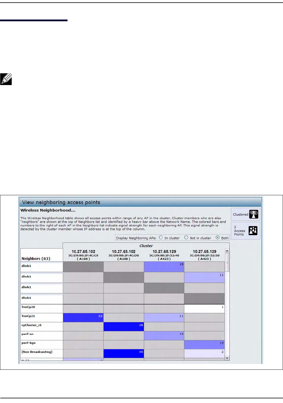
ViewingWirelessNeighborhoodInformation
D-Link UnifiedAccessPointAdministrator’sGuide
November2011 Page158
UnifiedAccessPointAdministrator’sGuide
ViewingWirelessNeighborhoodInformation
TheWirelessNeighborhoodshowsupto20accesspointsperradiowithinrangeofeverymemberofthe
cluster,showswhichaccesspointsarewithinrangeofwhichclustermembers,anddistinguishesbetween
clustermembersandnon‐members.
Foreachneighboraccesspoint,theWirelessNeighborhoodviewshowsidentifyinginformation(SSIDor
NetworkName,IPAddress,MACaddress)alongwithradiostatistics(signalstrength,channel,beaconinterval).
YoucanclickonanAPtogetadditionalstatisticsabouttheAPsinradiorangeofthecurrentlyselectedAP.
TheWirelessNeighborhoodviewcanhelpyou:
• Detectandlocateunexpected(orrogue)accesspointsinawirelessdomainsothatyoucantakeactionto
limitassociatedrisks
• Verifycoverageexpectations.ByassessingwhichAPsarevisibleatwhatsignalstrengthfromotherAPs,
youcanverifythatthedeploymentmeetsyourplanninggoals.
• Detectfaults.Unexpectedchangesinthecoveragepatternareevidentataglanceinthecolorcodedtable.
Figure49:WirelessNeighborhood
Note:TheWirelessNeighborhoodpageshowsupto20accesspointsperradio.Toseealltheaccess
pointsdetectedonagivenclusteraccesspoint,navigatetothatclustermember'swebinterfaceand
gototheStatus>NeighboringAccessPointspage.

ViewingWirelessNeighborhoodInformation
D-Link UnifiedAccessPointAdministrator’sGuide
November2011 Page159
UnifiedAccessPointAdministrator’sGuide
ThefollowingtabledescribesdetailsabouttheWirelessNeighborhoodinformation.
Table64:WirelessNeighborhoodInformation
Field Description
DisplayneighboringAPs Clickoneofthefollowingradiobuttonstochangetheview:
•Incluster—ShowsonlyneighborAPsthataremembersofthecluster
•Notincluster—ShowsonlyneighborAPsthatarenotclustermembers
•Both—ShowsallneighborAPs(clustermembersandnon‐members)
Cluster TheClusterlistatthetopofthetableshowsIPaddressesforallaccesspointsinthe
cluster.(ThisisthesamelistofclustermembersshownontheCluster>Access
Pointstab.)
IfthereisonlyoneAPinthecluster,onlyasingleIPaddresscolumnwillbe
displayedhere;indicatingthattheAPisclusteredwithitself.
YoucanclickonanIPaddresstoviewmoredetailsonaparticularAP.
Neighbors AccesspointswhichareneighborsofoneormoreoftheclusteredAPsarelistedin
theleftcolumnbySSID(NetworkName).
Anaccesspointwhichisdetectedasaneighborofaclustermembercanalsobea
clustermemberitself.Neighborswhoarealsoclustermembersarealwaysshown
atthetopofthelistwithaheavybaraboveandincludealocationindicator.
ThecoloredbarstotherightofeachAPintheNeighborslistshowsthesignal
strengthforeachoftheneighborAPsasdetectedbytheclustermemberwhoseIP
addressisshownatthetopofthecolumn.
Thecolorofthebarindicatesthesignalstrength:
•DarkBlueBar—Adarkbluebarandahighsignalstrengthnumber(forexample
50)indicatesgoodsignalstrengthdetectedfromtheNeighborseenbytheAP
whoseIPaddressislistedabovethatcolumn.
•LighterBlueBar—Alighterbluebarandalowersignalstrengthnumber(for
example20orlower)indicatesmediumorweaksignalstrengthfromthe
NeighborseenbytheAPwhoseIPaddressislistedabovethatcolumn
•WhiteBar—Awhitebarandthenumber0indicatesthataneighboringAPthat
wasdetectedbyoneoftheclustermemberscannotbedetectedbytheAP
whoseIPaddressiflistedabovethatcolumn.
•LightGrayBar—Alightgraybarandnosignalstrengthnumberindicatesa
NeighborthatisdetectedbyotherclustermembersbutnotbytheAPwhose
IPaddressislistedabovethatcolumn.
•DarkGrayBar—Adarkgraybarandnosignalstrengthnumberindicatesthisis
theAPwhoseIPaddressislistedabovethatcolumn(sinceitisnotapplicable
toshowhowwelltheAPcandetectitself).
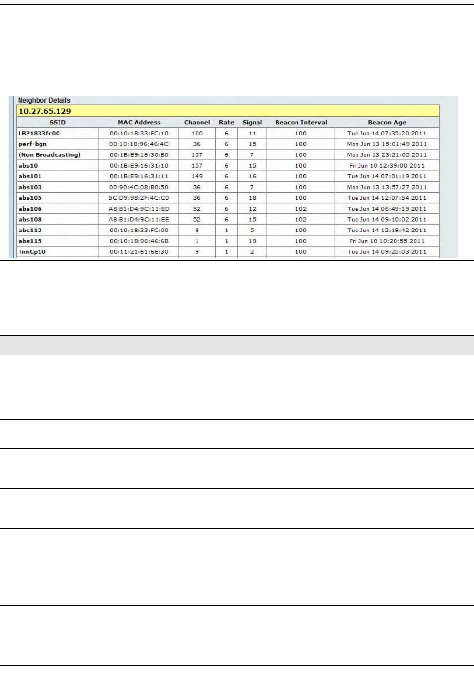
ViewingWirelessNeighborhoodInformation
D-Link UnifiedAccessPointAdministrator’sGuide
November2011 Page160
UnifiedAccessPointAdministrator’sGuide
ViewingDetailsforaClusterMember
ToviewdetailsonaclustermemberAP,clickontheIPaddressofaclustermemberatthetopofthepage.The
followingfigureshowstheNeighborDetailsforRadio1oftheAPwithanIPaddressof10.27.65.66.
Figure50:DetailsforaClusterMemberAP
ThefollowingtableexplainsthedetailsshownabouttheselectedAP.
Table65:ClusterMemberDetails
Field Description
SSID TheServiceSetIdentifier(SSID)fortheaccesspoint.
TheSSIDisanalphanumericstringofupto32charactersthatuniquelyidentifiesa
wirelesslocalareanetwork.ItisalsoreferredtoastheNetworkName.
AGuestnetworkandanInternalnetworkrunningonthesameaccesspointmustalways
havetwodifferentnetworknames.
MACAddress ShowstheMACaddressoftheneighboringaccesspoint.
AMACaddressisahardwareaddressthatuniquelyidentifieseachnodeofanetwork.
Channel Showsthechannelonwhichtheaccesspointiscurrentlybroadcasting.
TheChanneldefinestheportionoftheradiospectrumthattheradiousesfor
transmittingandreceiving.
Rate Showstherate(inmegabitspersecond)atwhichthisaccesspointiscurrently
transmitting.
ThecurrentratewillalwaysbeoneoftheratesshowninSupportedRates.
Signal Indicatesthestrengthoftheradiosignalemittingfromthisaccesspointasmeasuredin
decibels(Db).
BeaconInterval ShowstheBeaconintervalbeingusedbythisaccesspoint.
Beaconframesaretransmittedbyanaccesspointatregularintervalstoannouncethe
existenceofthewirelessnetwork.Thedefaultbehavioristosendabeaconframeonce
every100milliseconds(or10persecond).
BeaconAgeShowsthedateandtimeofthelastbeaconreceivedfromthisaccesspoint.

DefaultAPSettings
D-Link UnifiedAccessPointAdministrator’sGuide
November2011 Page161
UnifiedAccessPointAdministrator’sGuide
AppendixA:DefaultAPSettings
WhenyoufirstpoweronaUAP,ithasthedefaultsettingsshowninthefollowingtable.
Note:TheDWL‐3600APsupportsoneradio,anditiscapableofoperatingintheIEEE802.11b,
802.11g,and802.11n(2.4GHz)modes.Radio1(802.11a/n)settingsdonotapplytothe
DWL‐3600AP.
Table66:UAPDefaultSettings
Feature Default
SystemInformation
UserName admin
Password admin
EthernetInterfaceSettings
ConnectionType DHCP
DHCP Enabled
IPAddress 10.90.90.91(ifnoDHCPserverisavailable)
SubnetMask 255.0.0.0
DNSName None
ManagementVLANID 1
UntaggedVLANID 1
IPv6AdminMode Enabled
IPv6AutoConfigAdminMode Enabled
RadioSettings
Radio(1and2) On
Radio1IEEE802.11Mode 802.11a/n
Radio2IEEE802.11Mode 802.11b/g/n
802.11a/nChannel Auto
802.11b/g/nChannel Auto
Radio1ChannelBandwidth 40MHz
Radio2ChannelBandwidth 20MHz
PrimaryChannel Lower
ShortGuardIntervalSupported Yes
STBCMode On
Protection Auto
MaximumWirelessClients 200
TransmitPower 100percent

DefaultAPSettings
D-Link UnifiedAccessPointAdministrator’sGuide
November2011 Page162
UnifiedAccessPointAdministrator’sGuide
LegacyRateSetsSupported(Mbps) IEEE802.11a:54,48,36,24,18,12,9,6
IEEE802.11b:11,5.5,2,1
IEEE802.11g:54,48,36,24,18,12,11,9,6,5.5,2,1
LegacyRateSets(Mbps)
(Basic/Advertised)
IEEE802.11a:24,12,6
IEEE802.11b:2,1
IEEE802.11g:11,5.5,2,1
MCS(DataRate)Settings
(802.11nonly)
0–15Enabled
Broadcast/MulticastRateLimiting Disabled
FixedMulticastRate Auto
BeaconInterval 100
DTIMPeriod 2
FragmentationThreshold 2346
RTSThreshold 2347
TSPECMode Off
TSPECVoiceACMMode Off
VirtualAccessPointSettings
Status VAP0isenabledonbothradios,allotherVAPsdisabled
VLANID 1
NetworkName(SSID) dlink1throughdlink16
BroadcastSSID Allow
SecurityMode None(plaintext)
MACAuthenticationType None
RADIUSIPAddress 10.90.90.1
RADIUSKey secret
RADIUSAccounting Disabled
RedirectMode None
OtherDefaultSettings
WDSSettings None
STP Disabled
MACAuthentication Nostationsinlist
LoadBalancing Disabled
SNMP Enabled
ROSNMPCommunityName public
SNMPAgentPort 161
SNMPSetRequests Enabled
ManagedAPMode Enabled
Table66:UAPDefaultSettings(Cont.)
Feature Default
DefaultAPSettings
D-Link UnifiedAccessPointAdministrator’sGuide
November2011 Page163
UnifiedAccessPointAdministrator’sGuide
Authentication(802.1XSupplicant) Disabled
ManagementACL Disabled
HTTPAccess Enabled;disabledinManagedMode
HTTPSAccess Enabled;disabledinManagedMode
ConsolePortAccess Enabled
TelnetAccess Enabled;disabledinManagedMode
SSHAccess Enabled;disabledinManagedMode
WMM Enabled
EmailAlertAdminMode Down
Time Manual(Notset)
ClientQoSGlobalAdminMode Disabled
Per‐VAPClientQoSMode Disabled
Clustering Stopped
Table66:UAPDefaultSettings(Cont.)
Feature Default

ConfigurationExamples
D-Link UnifiedAccessPointAdministrator’sGuide
November2011 Page164
UnifiedAccessPointAdministrator’sGuide
AppendixB:ConfigurationExamples
ThisappendixcontainsexamplesofhowtoconfigureselectedfeaturesavailableontheUAP.Eachexample
containsproceduresonhowtoconfigurethefeaturebyusingtheWebinterface,CLI,andSNMP.
Thisappendixdescribeshowtoperformthefollowingprocedures:
•“ConfiguringaVAP”
•“ConfiguringRadioSettings”
•“ConfiguringtheWirelessDistributionSystem”
•“ClusteringAccessPoints”
•“ConfiguringClientQoS”
ForallSNMPexamples,theobjectsyouusetoAPareinaprivateMIB.Thepathtothetablesthatcontainthe
objectsisiso(1).org(3).dod(6).internet(1).private(4).enterprises(1).dlink(171).dlink‐products(10).dwl‐
ap(37).dwlWLANAP(26).
ConfiguringaVAP
ThisexampleshowshowtoconfigureVAP1withthefollowingnon‐defaultsettings:
• VLANID:2
• SSID:Marketing
•Security:WPAPersonalusingWPA2withCCMP(AES)
VAPConfigurationfromtheWebInterface
1. LogontotheAPandnavigatetotheManage>VAPpage.
2. IntheEnabledcolumnforVAP1,selectthecheckbox.
3. Enter2intheVLANIDcolumn.
4. IntheSSIDcolumn,deletetheexistingSSIDandtypeMarketing.
5. SelectWPAPersonalfromthemenuintheSecuritycolumn.
Additionalfieldsappear.
6. SelecttheWPA2andCCMP(AES)options,andcleartheWPAandTKIPoptions.
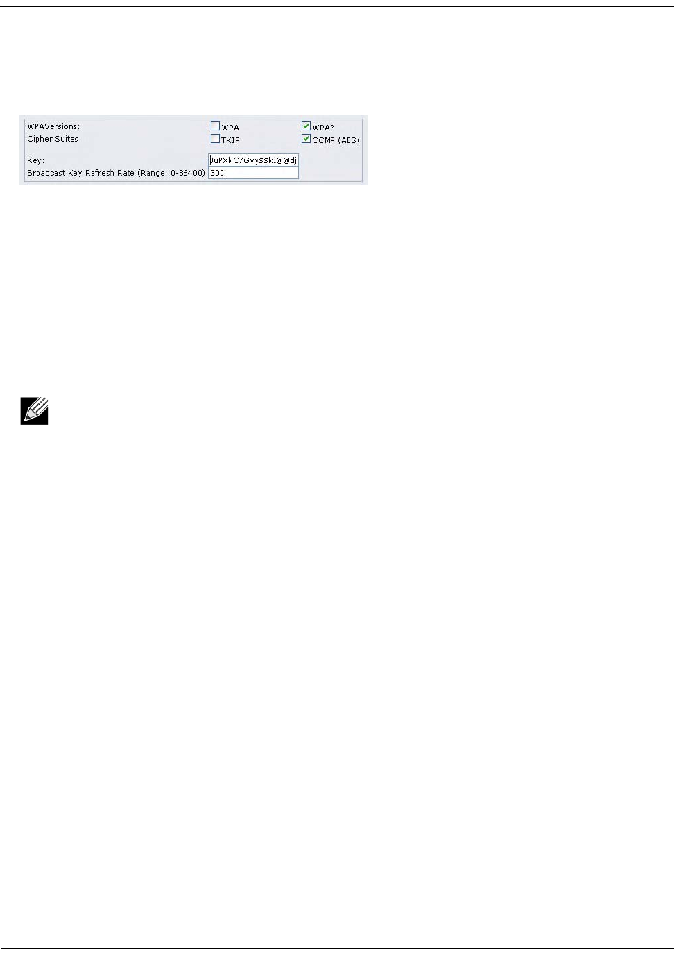
ConfiguringaVAP
D-Link UnifiedAccessPointAdministrator’sGuide
November2011 Page165
UnifiedAccessPointAdministrator’sGuide
7. EnteraWPAencryptionkeyintheKeyfield.
Thekeycanbeamixofalphanumericandspecialcharacters.Thekeyiscasesensitiveandcanbebetween
8and63characters.
8. ClickApplytoupdatetheAPwiththenewsettings.
VAPConfigurationfromtheCLI
1. ConnecttotheAPbyusingTelnet,SSHoraserialconnection.
2. EnableVAP1.
setvapvap1statusup
3. SettheVLANIDto2.
setvapvap1vlan‐id2
4. SettheSSIDtoMarketing.
setinterfacewlan0vap1ssidMarketing
5. SettheSecurityModetoWPAPersonal.
setinterfacewlan0vap1securitywpa‐personal
6. AllowWPA2clients,andnotWPAclients,toconnecttotheAP.
setbsswlan0bssvap1wpa‐allowedoff
setbsswlan0bssvap1wpa2‐allowedon
7. SettheCipherSuitetoCCMP(AES)only.
setbsswlan0bssvap1wpa‐cipher‐tkipoff
setbsswlan0bssvap1wpa‐cipher‐ccmpon
8. SetthePre‐sharedkey.
setinterfacewlan0vap1wpa‐personal‐keyJuPXkC7GvY$moQiUttp2
Ifthesharedsecretkeysincludesspaces,placethekeyinsidequotationmarks.
9. Usethefollowingcommandstoviewandverifythesettings.
getinterfacewlan0vap1detail
getvapvap1detail
Note:ThepreviouscommandsetstheVLANIDto2forVAP1onbothradios.TosettheVLANID
forVAP1onradiooneonly,usethefollowingcommand:set vap 1 with radio wlan0 to
vlan-id 2.

ConfiguringRadioSettings
D-Link UnifiedAccessPointAdministrator’sGuide
November2011 Page166
UnifiedAccessPointAdministrator’sGuide
VAPConfigurationUsingSNMP
1. LoadtheDLINK‐WLAN‐ACCESS‐POINT‐MIBmodule.
2. FromtheMIBtree,navigatetotheobjectsintheapVaptable.
3. WalktheapVapDescriptionobjecttoviewtheinstanceIDforVAP1(wlan0vap1).
VAP1onRadio1isinstance3.
4. UsetheapVapStatusobjecttosetthestatusofVAP1toup(1).
5. UsetheapVapVlanIDobjecttosettheVLANIDofVAP1to2.
6. NavigatetotheobjectsintheapIfConfigtable.
7. WalktheapIfConfigNameobjecttoviewtheinstanceIDforVAP1(wlan0vap1).
VAP1onRadio1isinstance3.
8. Setthevalueofinstance3intheapIfConfigSsidobjecttoMarketing.
9. Setthevalueofinstance3intheapIfConfigSecurityobjecttowpa‐personal(3).
10. Setthevalueofinstance3intheapIfConfigWpaPersonalKeyobjecttoJuPXkC7GvY$moQiUttp2,whichis
theWPApre‐sharedkey.
11. NavigatetotheobjectsintheapRadioBss>apBssTabletable.
12. WalktheapBssDescrobjecttoviewtheinstanceIDforVAP1.
VAP1onRadio1isinstance1.
13. Setthevalueofinstance1intheapBssWpaAllowedobjecttofalse(2).
14. Setthevalueofinstance1intheapBssWpaCipherTkipobjecttofalse(2).
15. Setthevalueofinstance1intheapBssWpaCipherCcmpobjecttotrue(1).
ConfiguringRadioSettings
ThisexampleshowshowtoconfigureRadio2withthefollowingsettings:
•Mode:IEEE802.11b/g/n
•Channel:6
•ChannelBandwidth:40MHz
•MaximumStations:100
•TransmitPower:75%
RadioConfigurationfromtheWebInterface
1. LogontotheAPandnavigatetotheManage>Radiopage.
2. Makesurethenumber2appearsintheRadiofieldandthatthestatusisOn.
3. FromtheModemenu,selectIEEE802.11b/g/n.
4. FromtheChannelfield,select6.
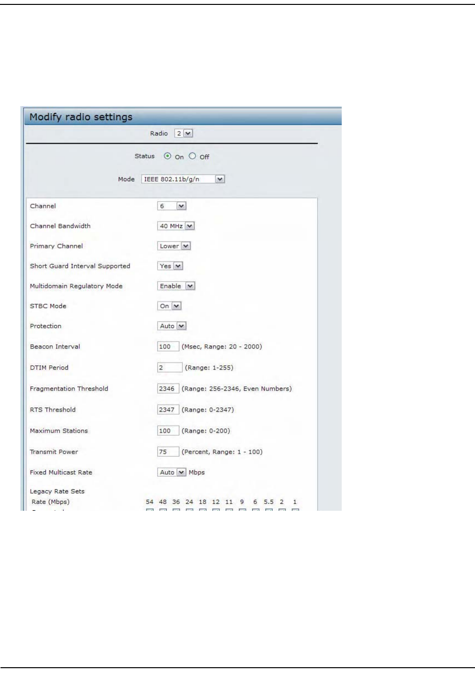
ConfiguringRadioSettings
D-Link UnifiedAccessPointAdministrator’sGuide
November2011 Page167
UnifiedAccessPointAdministrator’sGuide
5. FromtheChannelBandwidthfield,select40MHz.
6. IntheMaximumStationsfield,changethevalueto100.
7. IntheTransmitPowerfield,changethevalueto75.
ThefollowingimageshowstheRadiopagewiththesettingsspecifiedinthisexample.
8. ClickApplytoupdatetheAPwiththenewsettings.

ConfiguringRadioSettings
D-Link UnifiedAccessPointAdministrator’sGuide
November2011 Page168
UnifiedAccessPointAdministrator’sGuide
RadioConfigurationfromtheCLI
1. ConnecttotheAPbyusingTelnet,SSH,oraserialconnection.
2. TurnRadio2onifthestatusisnotcurrentlyup.
setradiowlan1statuson
3. SetthemodetoIEEE802.11b/g/n.
setradiowlan1modebg‐n
4. Setthechannelto6.
setradiowlan1channel‐policystatic
setradiowlan1static‐channel6
5. Setthechannelbandwidthto40MHz.
setradiowlan1n‐bandwidth40
6. Allowamaximumof100stationstoconnecttotheAPatatime.
setbsswlan1bssvap0max‐stations100
7. Setthetransmitpowerto75percent.
setradiowlan1tx‐power75
8. Viewinformationabouttheradiosettings.
getradiowlan1detail
RadioConfigurationUsingSNMP
1. LoadtheDLINK‐WLAN‐ACCESS‐POINT‐MIBmodule.
2. FromtheMIBtree,navigatetotheobjectsintheapRadiotable(apRadioBss>apRadioTable).
3. UsetheapRadioStatusobjecttosetthestatusofRadio2toup(1).
4. UsetheapRadioModeobjecttosettheRadio2modetoIEEE802.11b/g/n,whichisbg‐n(4).
5. UsetheapRadioChannelPolicyobjecttosetthechannelpolicytostatic(1),whichdisablestheautomatic
channelassignment.
6. UsetheapRadioStaticChannelobjecttosetthechannelto6.
7. UsetheapRadioChannelBandwithobjecttosetthechannelbandwidthforRadio2toforty‐MHz(2).
8. UsetheapRadioTxPowerobjecttosetthetransmissionpoweronRadio2to75.
9. NavigatetotheobjectsintheapBssTable.
10. UsetheapBssMaxStationsobjecttosetthevalueofthemaximumallowedstationsto100.
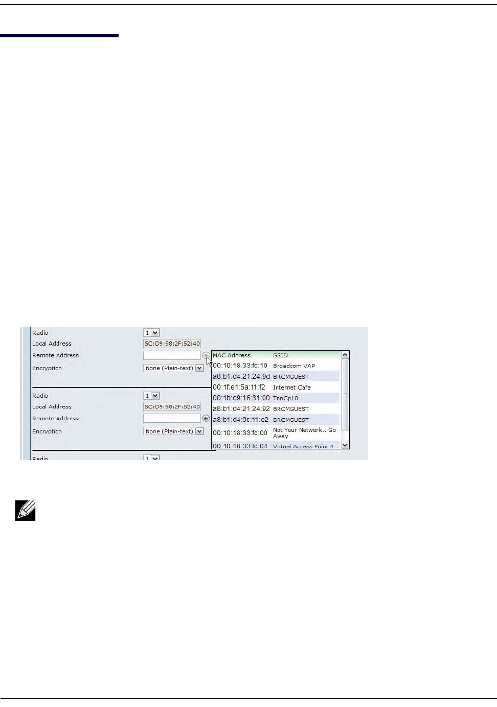
ConfiguringtheWirelessDistributionSystem
D-Link UnifiedAccessPointAdministrator’sGuide
November2011 Page169
UnifiedAccessPointAdministrator’sGuide
ConfiguringtheWirelessDistributionSystem
ThisexamplesshowshowtoconfigureaWDSlinkbetweentwoAPs.ThelocalAPisMyAP1andhasaMAC
addressof00:1B:E9:16:32:40,andtheremoteAPisMyAP2withaMACaddressof00:30:AB:00:00:B0.
TheWDSlinkhasthefollowingsettings,whichmustbeconfiguredonbothAPs:
• Encryption:WPA(PSK)
• SSID:wds‐link
•Key:abcdefghijk
WDSConfigurationfromtheWebInterface
TocreateaWDSlinkbetweenapairofaccesspoints“MyAP1”and“MyAP2”usethefollowingsteps:
1. LogontoMyAP1andnavigatetotheManage>WDSpage.
TheMACaddressforMyAP1(theaccesspointyouarecurrentlyviewing)isautomaticallyprovidedinthe
LocalAddressfield.
2. EntertheMACaddressforMyAP2intheRemoteAddressfield,orclickthearrownexttothefieldandselect
theMACaddressofMyAP2fromthepop‐uplist.
3. SelectWPA(PSK)fromtheEncryptionmenu.
Note:TheWPA(PSK)optionisavailableonlyifVAP0onRadio1usesWPA(PSK)asthesecurity
method.IfVAP0isnotsettoWPAPersonalorWPAEnterprise,youmustchooseeitherNone
(Plain‐text)orWEPforWDSlinkencryption.

ConfiguringtheWirelessDistributionSystem
D-Link UnifiedAccessPointAdministrator’sGuide
November2011 Page170
UnifiedAccessPointAdministrator’sGuide
4. Enterwds‐linkintheSSIDfieldandabcdefghijkintheKeyfield.
5. ClickApplytoapplytheWDSsettingstotheAP.
6. LogontoMyAP2andrepeatsteps2‐5(butbesuretousetheMACaddressofMyAP1intheRemoteAddress
field.
WDSConfigurationfromtheCLI
1. ConnecttotheMyAP1byusingTelnet,SSH,oraserialconnection.
2. ConfiguretheremoteMACaddressforMyAP2.
setinterfacewlan0wds0statusupremote‐mac00:30:AB:00:00:B0
3. SetWPA(PSK)astheencryptiontypeforthelink.
setinterfacewlan0wds0wds‐security‐policywpa‐personal
4. SettheSSIDontheWDSlink.
setinterfacewlan0wds0wds‐ssidwds‐link
5. Configuretheencryptionkey.
setinterfacewlan0wds0wds‐wpa‐psk‐keyabcdefghijk
6. AdministrativelyenabletheWDSlink.
setinterfacewlan0wds0statusup
7. PerformthesameconfigurationstepsonMyAP2.
Note:MyAP1andMyAP2mustbesettothesameIEEE802.11Modeandbetransmittingonthe
samechannel.

ConfiguringtheWirelessDistributionSystem
D-Link UnifiedAccessPointAdministrator’sGuide
November2011 Page171
UnifiedAccessPointAdministrator’sGuide
WDSConfigurationUsingSNMP
1. LoadtheFASTPATH‐WLAN‐ACCESS‐POINT‐MIBmodule.
2. FromtheMIBtree,navigatetotheobjectsintheapIfConfigtable.
3. WalktheapIfConfigNameobjecttoviewtheinstanceIDforthefirstWDSlink(wlan0wds0).
ThefirstWDSlinkisinstance1.
4. Setthevalueofinstance1intheapIfConfigRemoteMacobjectto00:30:AB:00:00:B0.
IntheMG‐Softbrowser,theformatfortheMACaddressvaluetosetis#0x000x300xAB0x000x000xB0.
5. Setthevalueofinstance1intheapIfConfigWdsSecPolicyobjecttoWPAPersonal(3).
6. Setthevalueofinstance1intheapIfConfigSsidobjecttowds‐link.
7. Setthevalueofinstance1intheapIfConfigWdsWpaPskKeyobjecttoabcdefthijk.
SomeMIBbrowsersrequirethatthevaluebeenteredinHEXvaluesratherthanASCIIvalues.
8. PerformthesameconfigurationstepsonMyAP2.
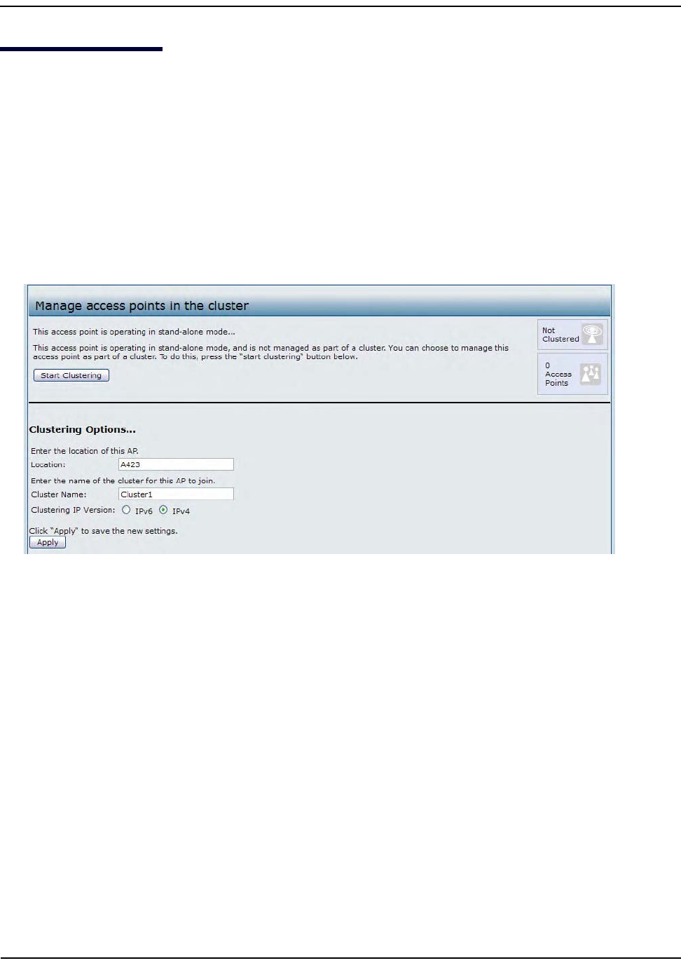
ClusteringAccessPoints
D-Link UnifiedAccessPointAdministrator’sGuide
November2011 Page172
UnifiedAccessPointAdministrator’sGuide
ClusteringAccessPoints
ThisexampleshowshowtoconfigureaclusterwithtwoAPsandtoenableautomaticchannelre‐
assigment.ThelocationofthelocalAPisRoom214,andtheclusternameisMyCluster.
ClusteringAPsbyUsingtheWebInterface
1. LogontotheAPandnavigatetotheCluster>AccessPointspage.
2. Ifclusteringhasstarted,clickStopClusteringsoyoucanchangetheClusteringOptions.
3. EntertheAPlocationandthenameoftheclusterforittojoin.
4. ClickApply.
5. ClickStartClusteringtoenabletheclusteringfeature.
Afteryourefreshthepage,otherAPsthatareonthesamebridgedsegment,haveradiosinthesame
operatingmode,areenabledforclustering,andhavethesameclusternameappearintheAccessPoints
table.
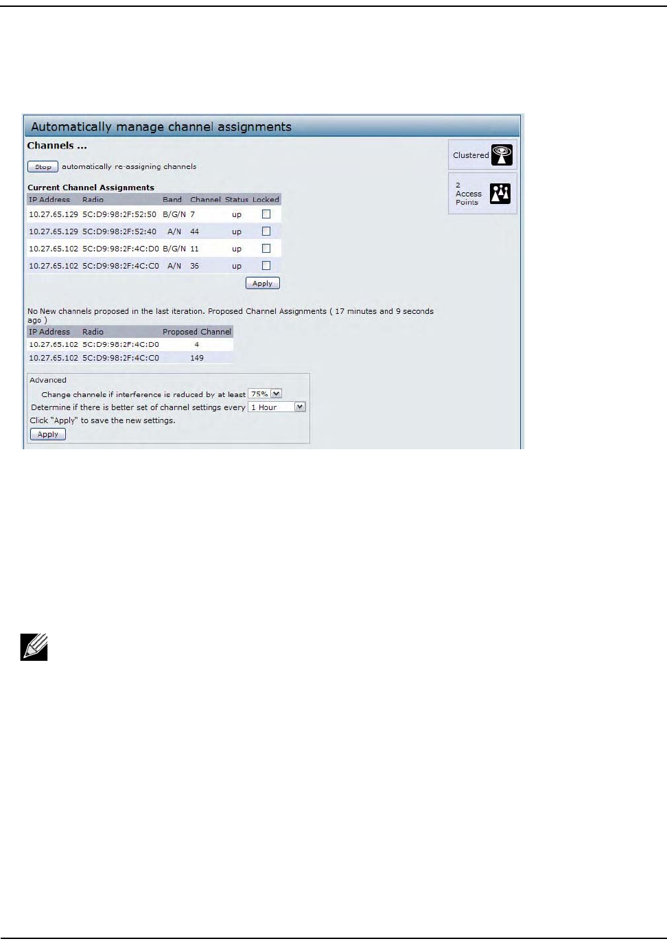
ClusteringAccessPoints
D-Link UnifiedAccessPointAdministrator’sGuide
November2011 Page173
UnifiedAccessPointAdministrator’sGuide
6. GototheChannelManagementpagetoviewthechannelassignments.
Atableonthepagedisplaysthecurrentchannelassignmentsandtheproposedchannelassignments.The
intervalsettingintheAdvancedsectiondeterminehowoftenproposedchangesareapplied.
ClusteringAPsbyUsingtheCLI
1. ConnecttotheAPbyusingTelnet,SSH,oraserialconnection.
2. Stopclusteringsoyoucanchangethelocationandclustername.
setclusterclustered0
3. SettheAPLocation.
setclustercluster‐name“Room214"
4. Settheclustername.
setclusterlocationMyCluster
5. Startclustering.
setclusterclustered1
6. ViewinformationabouttheclustersettingsontheAP.
getclusterdetail
7. Starttheautomaticchannelplanner.
setchannel‐plannerstatusup
8. Viewthesettingsfortheautomaticchannelplanner.
getchannel‐plannerdetail
Note:Iftheclusternameorclusterlocationhasspaces,youmustenclosethetextinquotation
markswhenyouenterthetextintheCLI,asthecommandexampleshows.Youdonotneedtouse
quotationmarkswhenyouentertextbyusingtheWebUI.
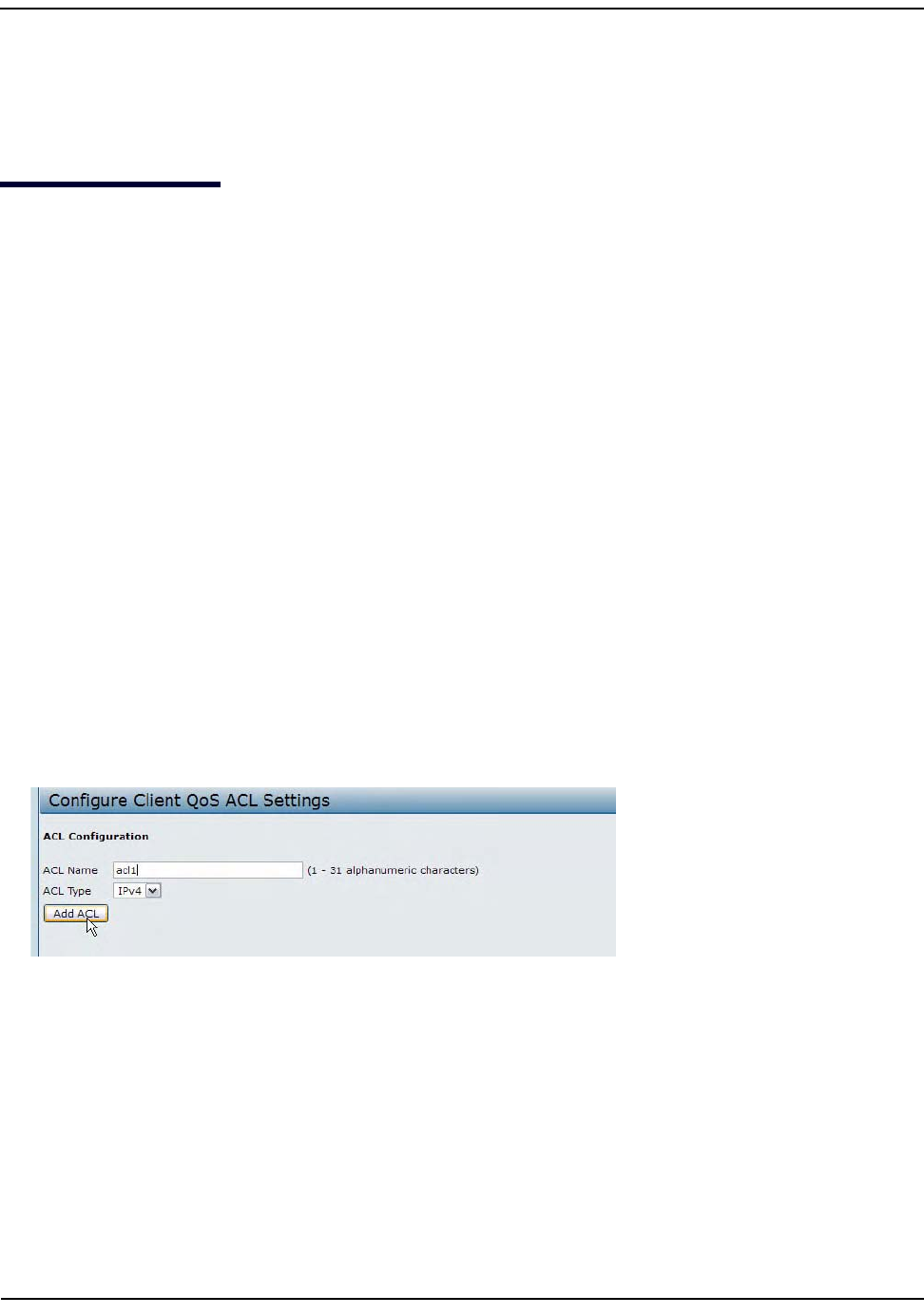
ConfiguringClientQoS
D-Link UnifiedAccessPointAdministrator’sGuide
November2011 Page174
UnifiedAccessPointAdministrator’sGuide
ClusteringAPsbyUsingSNMP
ClusterconfigurationbyusingSNMPisnotsupported.
ConfiguringClientQoS
ThisexampleshowshowtoenableclientQoS,configureanACLandaDiffServpolicyontheAP,andtoapply
theACLandthePolicytotraffictransmittedfromclientsassociatedwithVAP2andreceivedbytheAP.
TheIPv4ACLisnamedacl1andcontainstworules.ThefirstruleallowsHTTPtrafficfromthe192.168.1.0
subnet.ThesecondruleallowsallIPtrafficfromthemanagementstation(192.168.1.23).Allothertrafficis
deniedduetotheimplicitdenyallruleattheendoftheACL.TheACLisappliedtotheinboundinterfaceon
theAPsothatpacketsarecheckedwhentheAPreceivestrafficfromassociatedclients.
TheDiffServpolicyinthisexampleshowshowtoestablishdefaultDiffServbehaviorforclientsassociatingwith
theVAPthatdonotobtainaDiffServpolicynamethroughtheRADIUSserver.Voicetraffic(UDPpackets)
receivedfromclientsinthe192.168.1.0subnetthathastheVoIPserverasitsdestinationaddress
(192.168.2.200),ismarkedwiththeIPDSCPvalueforexpeditedforwardingsothatittakespriorityoverother
traffic.
ConfiguringQoSbyUsingtheWebInterface
ACLConfiguration
1. LogontotheAPandnavigatetotheClientQoS>ClientQoSACLpage.
2. Enteracl1intheACLNamefield,andclickAddACL.
Thescreenrefreshes,andadditionalfieldsappear.
3. FromtheActionmenu,selectPermit.
4. CleartheMatchEveryoption.
5. VerifythattheProtocoloptionisselectedandIPisselectedfromtheSelectFromListmenu.
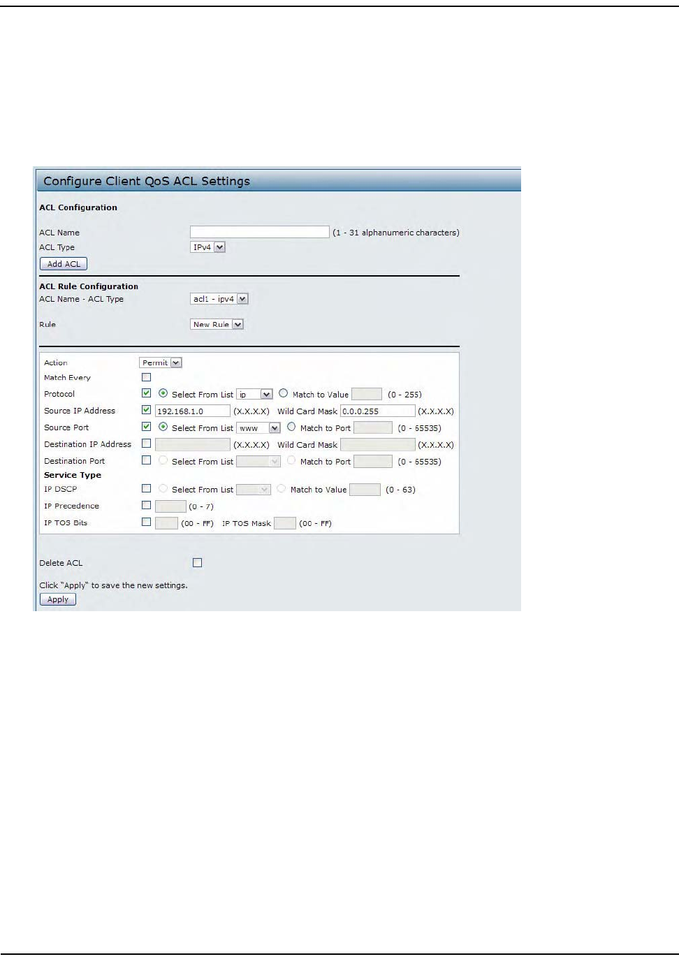
ConfiguringClientQoS
D-Link UnifiedAccessPointAdministrator’sGuide
November2011 Page175
UnifiedAccessPointAdministrator’sGuide
6. Configuretheremainingsettings:
•SourceIPAddress:192.168.1.0
•WildCardMask:0.0.0.255
•SourcePort:Selecttheoption
• SelectFromList(SourcePort):www
7. ClickApplytosavetherule.
8. SelectNewRulefromtheRulemenuandcreateanotherrulewiththefollowingsettings:
•Action:Permit
•MatchEvery:Cleartheoption
•Protocol:IP
• Address:192.168.1.23
•W
ildCardMask:0.0.0.0
9. ClickApplytosavetherule.
10. NavigatetotheClientQoS>VAPQoSParameterspage.
11. FortheClientQoSGlobalAdminModeoption,selectEnabled.
12. FromtheVAPmenu,selectVAP2.
13. SelecttheEnabledoptionforClientQoSMode.
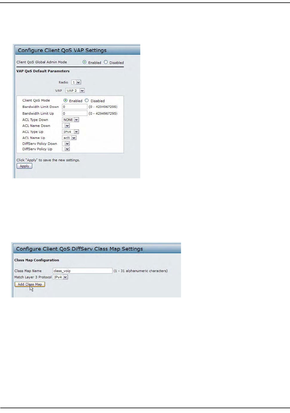
ConfiguringClientQoS
D-Link UnifiedAccessPointAdministrator’sGuide
November2011 Page176
UnifiedAccessPointAdministrator’sGuide
14. FromtheACLTypeUpmenu,selectIPv4.
15. FromtheACLNameUpmenu,selectacl1.
16. ClickApplytoupdatetheAPwiththeQoSsettings.
DiffServConfiguration
1. LogontotheAPandnavigatetotheClientQoS>ClassMappage.
2. Enterclass_voipintheClassMapNamefieldandclickAddClassMap.
Thepagerefreshesandadditionalfieldsappear.
3. SelecttheMatchEveryoptiontoindicatethatallmatchcriteriadefinedfortheclassmustbesatisfiedin
orderforapackettobeconsideredamatch.
4. SelectProtocol,andthenselectUDPfromtheSelectFromListfieldtodefineUDPasamatchcriteria.
5. SelectSourceIPAddressandenterthefollowinginformation:
• Address:192.168.1.0
•SourceIPMask:255.255.255.0
6. SelecttheDestinationIPAddressoptionandenterthefollowinginformationfortheVoIPserver:
• Address:192.168.2.200
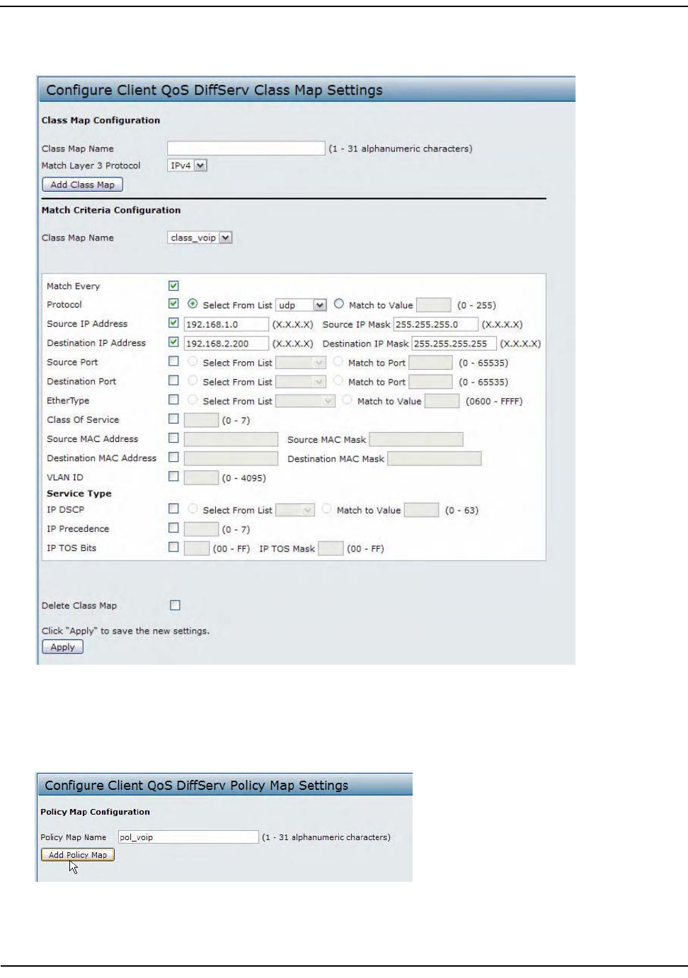
ConfiguringClientQoS
D-Link UnifiedAccessPointAdministrator’sGuide
November2011 Page177
UnifiedAccessPointAdministrator’sGuide
•DestinationIPMask:255.255.255.255
7. ClickApplytosavethematchcriteria.
8. NavigatetotheClientQoS>PolicyMappage.
9. Tocreateapolicy,enterpol_voipintothePolicyMapNamefield,andthenclickAddPolicyMap.
Thepagerefreshesandadditionalfieldsappear.
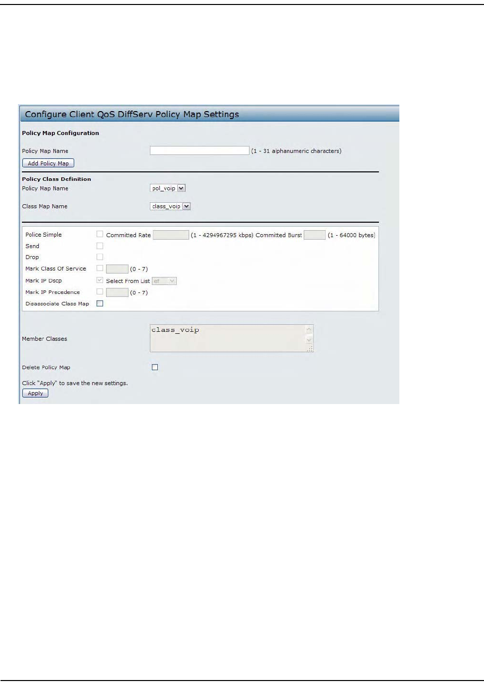
ConfiguringClientQoS
D-Link UnifiedAccessPointAdministrator’sGuide
November2011 Page178
UnifiedAccessPointAdministrator’sGuide
10. Fortheclass_voipclassmap,selecttheIPDSCPoption,andthenselecteffromtheSelectFromListmenu.
11. Trafficthatmeetsthecriteriadefinedintheclass_voipclassismarkedwithaDSCPvalueofEF(expedited
forwarding).
12. ClickApplytosavethepolicy.
13. NavigatetotheClientQoS>VAPQoSParameterspage.
14. SelectVAP2fromtheVAPmenu.
15. MakesurethattheClientQoSGlobalAdminModeandtheQoSModearebothenabled.
16. FromtheDiffServPolicyUpmenu,selectpol_voip.
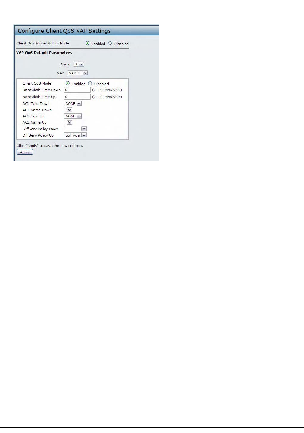
ConfiguringClientQoS
D-Link UnifiedAccessPointAdministrator’sGuide
November2011 Page179
UnifiedAccessPointAdministrator’sGuide
17. ClickApplytoupdatetheAPwiththeQoSsettings.
ConfiguringQoSbyUsingtheCLI
ACLConfiguration
1. ConnecttotheAP.
2. CreateanACLnamedacl1.
addaclacl1acl‐typeipv4
3. Addaruletoacl1thatallowsHTTPtrafficfromthe192.168.1.0subnet.
addruleacl‐nameacl2acl‐typeipv4actionpermitprotocolipsrc‐ip192.168.1.0src‐ip‐mask
0.0.0.255src‐porthttp
4. Addanotherruletoacl1thatallowsalltrafficfromthehostwithanIPaddressof192.168.1.23.
addruleacl‐nameacl2acl‐typeipv4actionpermitprotocolipsrc‐ip192.168.1.23src‐ip‐mask
0.0.0.0
5. EnableClientQoSontheAP.
setclient‐qosmodeup
6. EnableClientQoSonVAP2
setvapwlan0vap2qos‐modeup
7. Applyacl1toVAP2intheinbounddirection(fromtheclienttotheAP).
setvapwlan0vap2def‐acl‐upacl1
DiffServConfiguration
1. LogontotheAPCLI.
2. Createaclassmapnamedclass_voipandconfigureittomatchallUDPpacketsfromthe192.168.1.0
networkthathaveadestinationIPaddressof192.168.2.200(theVoIPserver).
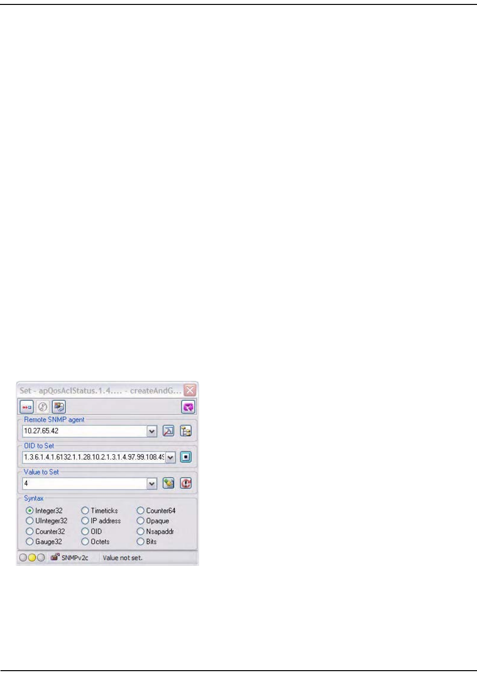
ConfiguringClientQoS
D-Link UnifiedAccessPointAdministrator’sGuide
November2011 Page180
UnifiedAccessPointAdministrator’sGuide
addclass‐mapclass_voipeveryyesprotocoludpsrc‐ip192.168.1.0src‐ip‐mask255.255.255.0dst‐
ip192.168.2.200dst‐ip‐mask255.255.255.255
3. Addapolicymapnamedpol_voip.
addpolicy‐mappol_voip
4. Definethepol_voippolicymapbyaddingtheclass_voipclassmapandspecifyingthatpacketsthatmatch
theclass_voipcriteriawillbemarkedwithaDSCPvalueofEF(expeditedforwarding).
addpolicy‐attrpolicy‐map‐namepol_voipclass‐map‐nameclass_voipmark‐ip‐dscpef
5. EnableClientQoSontheAP.
setclient‐qosmodeup
6. EnableClientQoSonVAP2
setvapwlan0vap2qos‐modeup
7. Applypol_voiptoVAP2intheinbounddirection(fromtheclienttotheAP).
setvapwlan0vap2def‐policy‐uppol_voip
ConfiguringQoSbyUsingSNMP
ACLConfiguration
1. LoadtheDLINK‐WLAN‐ACCESS‐POINT‐MIBmodule.
2. FromtheMIBtree,navigatetotheobjectsintheapQos>apAclTable.
3. UsetheapQosAclStatusobjecttocreatearowentrywithapQosAclNameandapQosAclTypeastheindexes
forapQosAclEntry.
ThenewapQosAclEntryvalueincludestheapQosAclType(1)followedbythenumberofcharactersinthe
name(4),andthentheASCIIcodeforthename.Inthisexample,acl1is97.99.108.49.Thevaluetosetis4,
whichisCreateandGo.
4. Addaruletoacl1thatallowsHTTPtrafficfromthe192.168.1.0subnet.
•Use1.3.6.1.4.1.6132.1.1.28.10.3.1.14.1.4.97.99.108.49.1tosettheapQosAclRuleStatusofRule1to
active(1)
IntheOID,the14(bold)isthesequenceidentifierfortheapQosAclRuleStatussobject,1istheACLtype,
4.97.99.108.49istheACLname(thenumberofcharactersfollowedbytheASCIIcode),andthefinal1
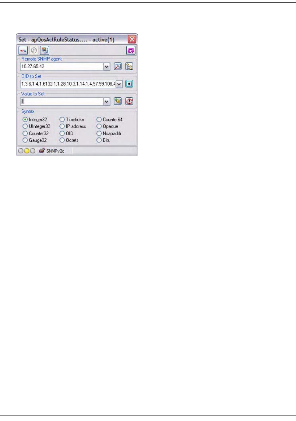
ConfiguringClientQoS
D-Link UnifiedAccessPointAdministrator’sGuide
November2011 Page181
UnifiedAccessPointAdministrator’sGuide
istheACLrulenumber.
•Use1.3.6.1.4.1.6132.1.1.28.10.3.1.4.1.4.97.99.108.49.1tosettheapQosAclRuleSrcIpAddresstoa
valueof192.168.1.0.
•Use1.3.6.1.4.1.6132.1.1.28.10.3.1.5.1.4.97.99.108.49.1tosettheapQosAclRuleSrcIpMasktoavalue
of0.0.0.255.
•Use1.3.6.1.4.1.6132.1.1.28.10.3.1.6.1.4.97.99.108.49.1tosetapQosAclRuleSrcProtocoltoavalueof
80(HTTP).
•Use1.3.6.1.4.1.6132.1.1.28.10.3.1.16.1.4.97.99.108.49.1tosetapQosAclRuleCommittoavalueof1
(true),whichsavestherule.
5. Addanotherruletoacl1thatallowsalltrafficfromthehostwithanIPaddressof192.168.1.23.
•Use1.3.6.1.4.1.6132.1.1.28.10.3.1.14.1.4.97.99.108.49.2tosettheapQosAclRuleStatusofRule2to
active(1)
•Use1.3.6.1.4.1.6132.1.1.28.10.3.1.4.1.4.97.99.108.49.2tosettheapQosAclRuleSrcIpAddresstoa
valueof192.168.1.23.
•Use1.3.6.1.4.1.6132.1.1.28.10.3.1.5.1.4.97.99.108.49.2tosettheapQosAclRuleSrcIpMasktoavalue
of0.0.0.0.
•Use1.3.6.1.4.1.6132.1.1.28.10.3.1.16.1.4.97.99.108.49.2tosetapQosAclRuleCommittoavalueof1
(true),whichsavestherule.
6. UsetheapQosGlobalModeobjecttosetthestatustoup(1),whichenablesClientQoSontheAP.
7. WalktheapVapDescriptionobjecttoviewtheinstanceIDforVAP2(wlan0vap2).
VAP2onRadio1isinstance5.
8. UsetheapVapQosModeobjecttosetthestatusofVAP2toup(1).
9. UsetheapVapAclUpobjecttoapplyacl1toVAP2intheinbounddirection(fromtheclienttotheAP).
TheACLnameisthetextstring,andnottheASCIIcode.
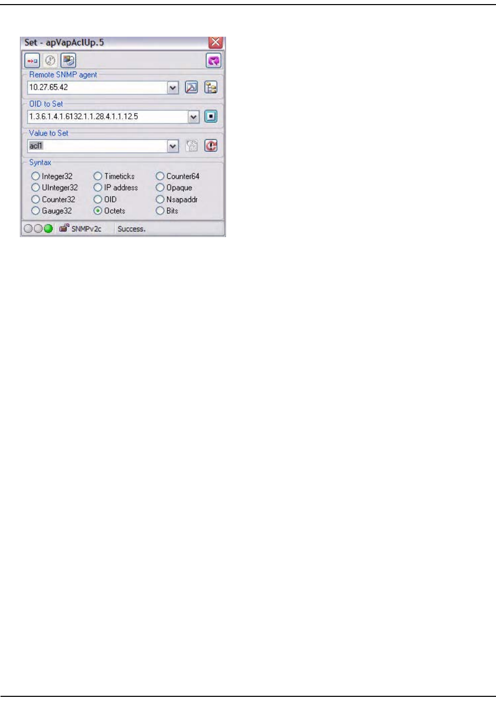
ConfiguringClientQoS
D-Link UnifiedAccessPointAdministrator’sGuide
November2011 Page182
UnifiedAccessPointAdministrator’sGuide
DiffServConfiguration
1. LoadtheDLINK‐WLAN‐ACCESS‐POINT‐MIBmodule.
2. FromtheMIBtree,navigatetotheobjectsintheapQos>apAclTable.
3. UsetheapQosDsClassMapStatusobjecttosetthestatusoftheclassmapnamedclass_voiptoCreateand
Go(4).
TheOIDtosetis1.3.6.1.4.1.6132.1.1.28.10.4.1.2.10.99.108.97.115.115.95.118.111.105.112,where10is
thenumberofcharacters,and99.108.97.115.115.95.118.111.105.112isclass_voipinASCIIcode.
4. Configureclass_voiptomatchallUDPpacketsfromthe192.168.1.0networkthathaveadestinationIP
addressof192.168.2.200(theVoIPserver).
•SetapQosDsClassMapMatchEverytotrue(1).
•SetapQosDsClassMapMatchProtocoltoUDP(17).
•SetapQosDsClassMapMatchSrcIpAddressto192.168.1.0.
•SetapQosDsClassMapMatchSrcIpMaskto255.255.255.0.
•SetapQosDsClassMapMatchDestIpAddressto192.168.2.200.
•SetapQosDsClassMapMatchDestIpMaskto255.255.255.255
•SetapQosDsClassMapMatchCommittotrue(1).
5. Createapolicymapnamedpol_voip(whichis112.111.108.95.118.111.105.112inASCII)bysettingthe
valueoftheOID1.3.6.1.4.1.6132.1.1.28.10.5.1.2.8.112.111.108.95.118.111.105.112toCreateandGo(4).
6. Definethepol_voippolicymapbyaddingtheclass_voipclassmapandspecifyingthatpacketsthatmatch
theclass_voipcriteriawillbemarkedwithaDSCPvalueofEF(expeditedforwarding).
•Set
apQosDsPolicyMapAttrStatus.8.112.111.108.95.118.111.105.112.10.99.108.97.115.115.95.118.111.1
05.112.1toavalueof4(CreateandGo)
•Set
apQosDsPolicyMapAttrMarkIpDscp.8.112.111.108.95.118.111.105.112.10.99.108.97.115.115.95.118.
111.105.112.1to46(whichistheequivalentofef).

ConfiguringClientQoS
D-Link UnifiedAccessPointAdministrator’sGuide
November2011 Page183
UnifiedAccessPointAdministrator’sGuide
7. EnableClientQoSontheAP.
setclient‐qosmodeup
8. UsetheapQosGlobalModeobjecttosetthestatustoup(1),whichenablesClientQoSontheAP.
9. WalktheapVapDescriptionobjecttoviewtheinstanceIDforVAP2(wlan0vap2).
VAP2onRadio1isinstance5.
10. UsetheapVapQosModeobjecttosetthestatusofVAP2toup(1).
11. UsetheapVapPolUpobjecttoapplypol_voiptoVAP2intheinbounddirection(fromtheclienttotheAP).
Thepolicynameisthetextstring,andnottheASCIIcode.
FederalCommunicationCommissionInterferenceStatement
ThisdevicecomplieswithPart15oftheFCCRules.Operationissubjectto
thefollowingtwoconditions:(1)Thisdevicemaynotcauseharmful
interference,and(2)thisdevicemustacceptanyinterferencereceived,
includinginterferencethatmaycauseundesiredoperation.
Thisequipmenthasbeentestedandfoundtocomplywiththelimitsfora
ClassBdigitaldevice,pursuanttoPart15oftheFCCRules. Theselimits
aredesignedtoprovidereasonableprotectionagainstharmfulinterferenceina
residentialinstallation.Thisequipmentgenerates,usesandcanradiateradio
frequencyenergyand,ifnotinstalledandusedinaccordancewiththe
instructions,maycauseharmfulinterferencetoradiocommunications.
However,thereisnoguaranteethatinterferencewillnotoccurinaparticular
installation. Ifthisequipmentdoescauseharmfulinterferencetoradioor
televisionreception,whichcanbedeterminedbyturningtheequipmentoff
andon,theuserisencouragedtotrytocorrecttheinterferencebyoneofthe
followingmeasures:
-Reorientorrelocatethereceivingantenna.
-Increasetheseparationbetweentheequipmentandreceiver.
-Connecttheequipmentintoanoutletonacircuitdifferentfromthat
towhichthereceiverisconnected.
-Consultthedealeroranexperiencedradio/TVtechnicianforhelp.
FCCCaution:Anychangesormodificationsnotexpresslyapprovedbythe
partyresponsibleforcompliancecouldvoidtheuser'sauthoritytooperatethis
equipment.
Thistransmittermustnotbeco-locatedoroperatinginconjunctionwithany
otherantennaortransmitter.

Radiation ExposureStatement:
ThisequipmentcomplieswithFCCradiationexposurelimitssetforthforan
uncontrolledenvironment.Thisequipmentshouldbeinstalledandoperated
withminimumdistance20cmbetweentheradiator&yourbody.
IndustryCanadastatement:
ThisdevicecomplieswithRSS-210oftheIndustryCanadaRules.Operationis
subjecttothefollowingtwoconditions:(1)Thisdevicemaynotcauseharmful
interference,and(2)thisdevicemustacceptanyinterferencereceived,
includinginterferencethatmaycauseundesiredoperation.
Cedispositifestconforme lanormeCNR-210d'IndustrieCanadaapplicable
auxappareilsradioexemptsdelicence.Sonfonctionnementestsujetauxdeux
conditionssuivantes:(1)ledispositifnedoitpasproduiredebrouillage
pr judiciable,et(2)cedispositifdoitacceptertoutbrouillagere u,ycompris
unbrouillagesusceptibledeprovoquerunfonctionnementind sirable.
RadiationExposureStatement:
ThisequipmentcomplieswithICradiationexposurelimitssetforthforan
uncontrolledenvironment.Thisequipmentshouldbeinstalledandoperated
withminimumdistance20cmbetweentheradiator&yourbody.
Dclarationd'expositionauxradiations:
Cet quipementestconformeauxlimitesd'expositionauxrayonnementsIC
tabliespourunenvironnementnoncontr l .Cet quipementdoit treinstall
etutilis avecunminimumde20cmdedistanceentrelasourcede
rayonnementetvotrecorps.
