D Link WL3610APA1 Unified AC Selectable Dual-band PoE Access Point User Manual 0420
D Link Corporation Unified AC Selectable Dual-band PoE Access Point 0420
D Link >
Contents
- 1. Users Manual_1
- 2. Users Manual_2
- 3. User Manual
Users Manual_1

UNIFIED ACCESS POINT
ADMINISTRATOR’S GUIDE
PRODUCT MODEL: DWL-2600AP, DWL-3600AP, DWL-3610AP, DWL-6600AP,
DWL-6610AP, DWL-6700AP, DWL-8600AP, DWL-8610AP, DWL-8710AP
UNIFIED WIRED & WIRELESS ACCESS SYSTEM
RELEASE 6.40
© COPYRIGHT 2016. ALL RIGHTS RESERVED

Unied Access Point Administrator’s Guide
Unied Access Point Administrator’s Guide
Page 2
May 2016
Table of Contents
Section 1 - About This Document ............................................................................................9
Document Organization ......................................................................................................................................... 9
Additional Documentation ..................................................................................................................................... 9
Document Conventions ......................................................................................................................................... 9
Online Help, Supported Browsers, and Limitations ............................................................................................. 10
Section 2 - Getting Started ...................................................................................................... 11
Administrator’s Computer Requirements ............................................................................................................ 11
Wireless Client Requirements ............................................................................................................................. 12
Dynamic and Static IP Addressing on the AP ...................................................................................................... 13
Recovering an IP Address ............................................................................................................................. 13
Discovering a Dynamically Assigned IP Address .......................................................................................... 13
Installing the UAP ................................................................................................................................................ 13
Basic Settings ...................................................................................................................................................... 16
Connecting to the AP Web Interface by Using the IPv6 Address .................................................................. 17
Using the CLI to View the IP Address.................................................................................................................. 17
Conguring the Ethernet Settings ....................................................................................................................... 18
Using the CLI to Congure Ethernet Settings ............................................................................................... 18
Conguring IEEE 802.1X Authentication ............................................................................................................. 19
Using the CLI to Congure 802.1X Authentication Information ..................................................................... 20
Verifying the Installation ...................................................................................................................................... 20
Conguring Security on the Wireless Access Point ............................................................................................. 21
Section 3 - Viewing Access Point Status ...............................................................................22
Viewing Interface Status ...................................................................................................................................... 22
Wired Settings (Internal Interface) ................................................................................................................ 22
Wireless Settings .......................................................................................................................................... 22
Viewing Events .................................................................................................................................................... 23
Conguring Persistent Logging Options ........................................................................................................ 23
Conguring the Log Relay Host for Kernel Messages .................................................................................. 24
Enabling or Disabling the Log Relay Host on the Events Page .................................................................... 24
Viewing Transmit and Receive Statistics ............................................................................................................. 25
Viewing Associated Wireless Client Information ................................................................................................. 26
Viewing TSPEC Client Associations .................................................................................................................... 26
Link Integrity Monitoring ................................................................................................................................ 28
Viewing Rogue AP Detection............................................................................................................................... 28
Saving and Importing the Known AP List ...................................................................................................... 30
Viewing Managed AP DHCP Information ............................................................................................................ 31
Viewing TSPEC Status and Statistics Information .............................................................................................. 31
Viewing TSPEC AP Statistics Information ........................................................................................................... 32
Viewing Radio Statistics Information ................................................................................................................... 33
Viewing Email Alert Operational Status ............................................................................................................... 34
Section 4 - Managing the Access Point .................................................................................35
Ethernet Settings ................................................................................................................................................. 35
Wireless Settings ................................................................................................................................................. 37
Using the 802.11h Wireless Mode ................................................................................................................. 39
Enabling AeroScout™ Engine Support ......................................................................................................... 39
Modifying Radio Settings ..................................................................................................................................... 40
Conguring Radio and VAP Scheduler................................................................................................................ 44
Scheduler Association Settings ........................................................................................................................... 46
Virtual Access Point Settings ............................................................................................................................... 47
None (Plain-text) ........................................................................................................................................... 50
Static WEP .................................................................................................................................................... 50
IEEE 802.1X .................................................................................................................................................. 51
WPA Personal ............................................................................................................................................... 53
WPA Enterprise ............................................................................................................................................. 54
Conguring the Wireless Distribution System (WDS) ......................................................................................... 56
WEP on WDS Links ...................................................................................................................................... 57
WPA/PSK on WDS Links .............................................................................................................................. 58

Unied Access Point Administrator’s Guide
Unied Access Point Administrator’s Guide
Page 3
May 2016
Controlling Access by MAC Authentication ......................................................................................................... 58
Conguring a MAC Filter and Station List on the AP..................................................................................... 59
Conguring MAC Authentication on the RADIUS Server .............................................................................. 59
Conguring Load Balancing ................................................................................................................................ 60
Managed Access Point Overview ........................................................................................................................ 60
Transitioning Between Modes ....................................................................................................................... 61
Conguring Managed Access Point Settings ................................................................................................ 61
Conguring 802.1X Authentication ...................................................................................................................... 62
Creating a Management Access Control List (ACL) ............................................................................................ 63
Section 5 - Conguring Access Point Services ....................................................................65
Web Server Settings ........................................................................................................................................... 65
Conguring SNMP on the Access Point .............................................................................................................. 66
Setting the SSH Status ........................................................................................................................................ 68
Setting the Telnet Status ..................................................................................................................................... 69
Conguring Quality of Service ............................................................................................................................. 69
Conguring Email Alert ........................................................................................................................................ 72
Enabling the Time Settings (NTP) ....................................................................................................................... 73
Section 6 - Conguring SNMPv3 ............................................................................................75
Conguring SNMPv3 Views ................................................................................................................................ 75
Conguring SNMPv3 Groups .............................................................................................................................. 76
Conguring SNMPv3 Users ................................................................................................................................ 77
Conguring SNMPv3 Targets .............................................................................................................................. 78
Section 7 - Maintaining the Access Point ..............................................................................79
Saving the Current Conguration to a Backup File ............................................................................................. 79
Restoring the Conguration from a Previously Saved File .................................................................................. 80
Performing AP Maintenance ................................................................................................................................ 81
Resetting the Factory Default Conguration ................................................................................................. 81
Rebooting the Access Point .......................................................................................................................... 81
Upgrading the Firmware ...................................................................................................................................... 81
Packet Capture Conguration and Settings ........................................................................................................ 83
Packet Capture Status .................................................................................................................................. 83
Packet Capture Parameter Conguration ..................................................................................................... 84
Packet File Capture ....................................................................................................................................... 84
Remote Packet Capture ................................................................................................................................ 85
Packet Capture File Download ...................................................................................................................... 87
Section 8 - Conguring Client Quality of Service (QoS) ......................................................88
Conguring VAP QoS Parameters ...................................................................................................................... 88
Managing Client QoS ACLs ................................................................................................................................. 89
IPv4 and IPv6 ACLs ...................................................................................................................................... 89
MAC ACLs ..................................................................................................................................................... 90
ACL Conguration Process ........................................................................................................................... 90
Creating a DiffServ Class Map ............................................................................................................................ 95
Dening DiffServ ........................................................................................................................................... 96
Creating a DiffServ Policy Map ......................................................................................................................... 100
Client QoS Status .............................................................................................................................................. 101
Conguring RADIUS-Assigned Client QoS Parameters ................................................................................... 102
Section 9 - Clustering Multiple APs .....................................................................................104
Managing Cluster Access Points in the Cluster ................................................................................................. 104
Clustering APs ............................................................................................................................................. 104
Viewing and Conguring Cluster Members ................................................................................................. 104
Removing an Access Point from the Cluster ............................................................................................... 106
Adding an Access Point to a Cluster ........................................................................................................... 106
Navigating to Conguration Information for a Specic AP........................................................................... 106
Navigating to an AP by Using its IP Address in a URL ................................................................................ 106
Managing Cluster Sessions ............................................................................................................................... 106
Sorting Session Information ........................................................................................................................ 107
Conguring and Viewing Channel Management Settings ................................................................................. 108
Stopping/Starting Automatic Channel Assignment ...................................................................................... 108
Viewing Current Channel Assignments and Setting Locks ......................................................................... 109

Unied Access Point Administrator’s Guide
Unied Access Point Administrator’s Guide
Page 4
May 2016
Viewing the Last Proposed Set of Changes ................................................................................................ 109
Conguring Advanced Settings ................................................................................................................... 109
Viewing Wireless Neighborhood Information .................................................................................................... 110
Viewing Details for a Cluster Member ......................................................................................................... 112
Appendix A - Default AP Settings ......................................................................................... 113
Appendix B - Conguration Examples ................................................................................115
Conguring a VAP ............................................................................................................................................. 115
VAP Conguration from the Web Interface ................................................................................................. 115
VAP Conguration from the CLI .................................................................................................................. 116
VAP Conguration Using SNMP ................................................................................................................. 116
Conguring Radio Settings ................................................................................................................................ 117
Radio Conguration from the Web Interface ............................................................................................... 117
Radio Conguration from the CLI ................................................................................................................ 117
Radio Conguration Using SNMP ............................................................................................................... 118
Conguring the Wireless Distribution System ................................................................................................... 118
WDS Conguration from the Web Interface ................................................................................................ 118
WDS Conguration from the CLI ................................................................................................................. 119
WDS Conguration Using SNMP ................................................................................................................ 119
Clustering Access Points ................................................................................................................................... 119
Clustering APs by Using the Web Interface ................................................................................................ 119
Clustering APs by Using the CLI ................................................................................................................. 120
Clustering APs by Using SNMP .................................................................................................................. 120
Conguring Client QoS ..................................................................................................................................... 121
Conguring QoS by Using the Web Interface ............................................................................................. 121
Conguring QoS by Using the CLI .............................................................................................................. 124
Appendix C - DWL-6700AP Prole and Conguration Table .............................................127

Unied Access Point Administrator’s Guide
Unied Access Point Administrator’s Guide
Page 5
May 2016
List of Figures
Figure 1 - Administrator UI Online Help ................................................................................................................... 10
Figure 2 - Web UI Login Prompt .............................................................................................................................. 14
Figure 3 - Provide Basic Settings ............................................................................................................................ 15
Figure 4 - Command Line Interface (CLI) Connection ............................................................................................ 18
Figure 5 - Viewing Interface Status ......................................................................................................................... 22
Figure 6 - Viewing Events ........................................................................................................................................ 23
Figure 7 - Viewing Trafc Statistics ......................................................................................................................... 25
Figure 8 - Viewing Client Association Information ................................................................................................... 26
Figure 9 - Viewing TSPEC Client Associations ....................................................................................................... 27
Figure 10 - Viewing Rogue and Known Access Points............................................................................................ 28
Figure 11 - Managed AP DHCP Information ............................................................................................................ 31
Figure 12 - Viewing TSPEC Status and Statistics ................................................................................................... 31
Figure 13 - View TSPEC Status and Statistics ........................................................................................................ 32
Figure 14 - View Radio Statistics ............................................................................................................................. 33
Figure 15 - Email Alert Operational Status .............................................................................................................. 34
Figure 16 - Modify Ethernet (Wired) settings ........................................................................................................... 35
Figure 17 - Modify Wireless Settings ....................................................................................................................... 37
Figure 18 - Modify Radio Settings ........................................................................................................................... 40
Figure 19 - Scheduler Conguration ....................................................................................................................... 45
Figure 20 - Scheduler Conguration (Modify Rule) ................................................................................................. 46
Figure 21 - Scheduler Association Settings ............................................................................................................. 46
Figure 22 - Modify Virtual Access Point Settings ..................................................................................................... 48
Figure 23 - Modify Virtual Access Point Settings (Static WEP) ............................................................................... 50
Figure 24 - Modify Virtual Access Point Settings (IEEE802.1X) .............................................................................. 52
Figure 25 - Modify Virtual Access Point Settings (WPA Personal) .......................................................................... 53
Figure 26 - Modify Virtual Access Point Settings (WPA Enterprise) ........................................................................ 54
Figure 27 - Congure WDS Bridges ........................................................................................................................ 57
Figure 28 - Congure MAC Authentication .............................................................................................................. 59
Figure 29 - Modify Load Balancing Settings ............................................................................................................ 60
Figure 30 - Congure Managed AP Wireless Switch Parameters ........................................................................... 62
Figure 31 - Modify 802.1X Supplicant Authentication Settings ................................................................................ 63
Figure 32 - Congure Management Access Control Parameters ............................................................................ 64
Figure 33 - Congure Web Server Settings ............................................................................................................. 65
Figure 34 - SNMP Conguration ............................................................................................................................. 67
Figure 35 - Set SSH Status ..................................................................................................................................... 68
Figure 36 - Set Telnet Status ................................................................................................................................... 69
Figure 37 - Modify QoS Queue Parameters ............................................................................................................ 70
Figure 38 - Email Alerts Conguration ..................................................................................................................... 72
Figure 39 - Time Settings (NTP) .............................................................................................................................. 74
Figure 40 - SNMPv3 Views Conguration ............................................................................................................... 75
Figure 41 - SNMPv3 Groups Conguration ............................................................................................................. 76
Figure 42 - SNMPv3 User Conguration ................................................................................................................. 77
Figure 43 - SNMPv3 Targets Conguration ............................................................................................................. 78
Figure 44 - Manage this Access Point’s Conguration - Save (TFTP) .................................................................... 79
Figure 45 - Manage this Access Point’s Conguration - Save (HTTP) .................................................................... 79
Figure 46 - Conrmation Prompt ............................................................................................................................. 80
Figure 47 - Manage this Access Point’s Conguration - Restore (TFTP) ................................................................ 80
Figure 48 - Manage this Access Point’s Conguration - Restore (HTTP) ............................................................... 80
Figure 49 - Performing AP Maintenance ................................................................................................................. 81
Figure 50 - Manage Firmware (TFTP) ..................................................................................................................... 82
Figure 51 - Manage Firmware (HTTP) .................................................................................................................... 82
Figure 52 - Packet Capture Conguration & Settings ............................................................................................. 83
Figure 53 - Packet Capture Status .......................................................................................................................... 84
Figure 54 - Packet Capture Conguration ............................................................................................................... 84
Figure 55 - Packet File Capture .............................................................................................................................. 85
Figure 56 - Remote Packet Capture ........................................................................................................................ 86
Figure 57 - Packet Capture File Download ............................................................................................................. 87
Figure 58 - Congure Client QoS VAP Settings ...................................................................................................... 88
Figure 59 - Congure Client QoS ACL Settings ...................................................................................................... 90

Unied Access Point Administrator’s Guide
Unied Access Point Administrator’s Guide
Page 6
May 2016
Figure 60 - Congure Client QoS DiffServ Class Map Settings .............................................................................. 96
Figure 61 - Congure Client QoS DiffServ Policy Map Settings ............................................................................ 100
Figure 62 - QoS Conguration Status For Associated Clients .............................................................................. 101
Figure 63 - Manage Access Points In The Cluster (Passive) ................................................................................ 104
Figure 64 - Manage Access Points In The Cluster (Active) ................................................................................... 105
Figure 65 - Manage Sessions Associated With The Cluster ................................................................................. 107
Figure 66 - Automatically Manage Channel Assignments ..................................................................................... 108
Figure 67 - View Neighboring Access Points ..........................................................................................................111
Figure 68 - Viewing Details For A Cluster Member ................................................................................................ 112
Figure 69 - VAP Conguration from the Web Interface ......................................................................................... 115
Figure 70 - Radio Conguration from the Web Interface ....................................................................................... 117
Figure 71 - WDS Conguration from the Web Interface ........................................................................................ 118
Figure 72 - Clustering APs by Using the Web Interface (Passive) ........................................................................ 119
Figure 73 - Clustering APs by Using the Web Interface (Active) ........................................................................... 120
Figure 74 - Conguring QoS by Using the Web Interface (ACL Name) ................................................................ 121
Figure 75 - Conguring QoS by Using the Web Interface (Rule1) ........................................................................ 121
Figure 76 - Conguring QoS by Using the Web Interface (Rule2) ........................................................................ 122
Figure 77 - Conguring QoS by Using the Web Interface (VAP QoS Parameters) ............................................... 122
Figure 78 - Conguring QoS by Using the Web Interface (Class Map Name) ...................................................... 123
Figure 79 - Conguring QoS by Using the Web Interface (Rule) .......................................................................... 123
Figure 80 - Congure Client QoS DiffServ Policy Map Settings (Policy Map Name) ............................................ 123
Figure 81 - Congure Client QoS DiffServ Policy Map Settings (Rule) ................................................................. 124
Figure 82 - Congure Client QoS VAP Settings .................................................................................................... 124

Unied Access Point Administrator’s Guide
Unied Access Point Administrator’s Guide
Page 7
May 2016
List of Tables
Table 1 - Typographical Conventions ...................................................................................................................... 10
Table 2 - Requirements for the Administrator’s Computer ....................................................................................... 12
Table 3 - Requirements for Wireless Clients ........................................................................................................... 12
Table 4 - Basic Settings Page ................................................................................................................................. 17
Table 5 - CLI Commands for Ethernet Setting ........................................................................................................ 19
Table 6 - CLI Commands for the 802.1X Supplicant ............................................................................................... 20
Table 7 - Logging Options ....................................................................................................................................... 24
Table 8 - Log Relay Host ......................................................................................................................................... 24
Table 9 - Transmit/Receive ...................................................................................................................................... 26
Table 10 - Associated Clients .................................................................................................................................. 26
Table 11 - TSPEC Client Associations ..................................................................................................................... 28
Table 12 - Rogue AP Detection ............................................................................................................................... 30
Table 13 - TSPEC Status and Statistics .................................................................................................................. 32
Table 14 - TSPEC AP Statistics ............................................................................................................................... 33
Table 15 - Radio Statistics Information .................................................................................................................... 34
Table 16 - Email Alert Status ................................................................................................................................... 34
Table 17 - Ethernet Settings .................................................................................................................................... 36
Table 18 - Wireless Settings .................................................................................................................................... 39
Table 19 - Radio Settings ........................................................................................................................................ 44
Table 20 - Scheduler Conguration ......................................................................................................................... 45
Table 21 - Scheduler Association Settings .............................................................................................................. 47
Table 22 - Virtual Access Point Settings .................................................................................................................. 50
Table 23 - Static WEP .............................................................................................................................................. 51
Table 24 - IEEE 802.1X ........................................................................................................................................... 53
Table 25 - WPA Personal ......................................................................................................................................... 54
Table 26 - WPA Enterprise ....................................................................................................................................... 56
Table 27 - WDS Settings ......................................................................................................................................... 57
Table 28 - WEP on WDS Links ................................................................................................................................ 58
Table 29 - WPA/PSK on WDS Links ........................................................................................................................ 58
Table 30 - MAC Authentication ................................................................................................................................ 60
Table 31 - RADIUS Server Attributes for MAC Authentication ................................................................................. 60
Table 32 - Load Balancing ....................................................................................................................................... 61
Table 33 - Managed Access Point ........................................................................................................................... 62
Table 34 - IEEE 802.1X Supplicant Authentication .................................................................................................. 63
Table 35 - Management ACL ................................................................................................................................... 64
Table 36 - Web Server Settings ............................................................................................................................... 66
Table 37 - SNMP Settings ....................................................................................................................................... 68
Table 38 - SSH Settings .......................................................................................................................................... 69
Table 39 - Telnet Settings ........................................................................................................................................ 69
Table 40 - QoS Settings .......................................................................................................................................... 72
Table 41 - Email Alert Conguration ........................................................................................................................ 73
Table 42 - NTP Settings ........................................................................................................................................... 74
Table 43 - SNMPv3 Views ....................................................................................................................................... 75
Table 44 - SNMPv3 Groups ..................................................................................................................................... 77
Table 45 - SNMPv3 Users ....................................................................................................................................... 77
Table 46 - SNMPv3 Targets ..................................................................................................................................... 78
Table 47 - Packet Capture Status ............................................................................................................................ 84
Table 48 - Packet Capture Conguration ................................................................................................................ 84
Table 49 - Packet File Capture ................................................................................................................................ 85
Table 50 - Remote Packet Capture ......................................................................................................................... 87
Table 51 - Packet Capture File Download ............................................................................................................... 87
Table 52 - VAP QoS Parameters ............................................................................................................................. 89
Table 53 - ACL Conguration ................................................................................................................................... 95
Table 54 - DiffServ Class Map ................................................................................................................................. 99
Table 55 - DiffServ Policy Map .............................................................................................................................. 101
Table 56 - Client QoS Status ................................................................................................................................. 102
Table 57 - Client QoS RADIUS Attributes .............................................................................................................. 103
Table 58 - Access Points in the Cluster ................................................................................................................. 105
Table 59 - Cluster Options ..................................................................................................................................... 105

Unied Access Point Administrator’s Guide
Unied Access Point Administrator’s Guide
Page 8
May 2016
Table 60 - Session Management ........................................................................................................................... 107
Table 61 - Channel Assignments ........................................................................................................................... 109
Table 62 - Last Proposed Changes ....................................................................................................................... 109
Table 63 - Advanced Channel Management Settings ........................................................................................... 110
Table 64 - Wireless Neighborhood Information ......................................................................................................111
Table 65 - Cluster Member Details ........................................................................................................................ 112
Table 66 - UAP Default Settings ............................................................................................................................ 114

Unied Access Point Administrator’s Guide
Unied Access Point Administrator’s Guide
Page 9
May 2016
Section 1 - About This Document
Section 1 - About This Document
This guide describes setup, conguration, administration and maintenance for the D-Link DWL-x600AP Unied Access
Point (UAP) on a wireless network.
Document Organization
The Unied Access Point Administrator’s Guide contains the following sections:
•) “Section 1 - About This Document” on page 9
•) “Section 2 - Getting Started” on page 11
•) “Section 3 - Viewing Access Point Status” on page 22
•) “Section 4 - Managing the Access Point” on page 35
•) “Section 5 - Conguring Access Point Services” on page 65
•) “Section 6 - Conguring SNMPv3” on page 75
•) “Section 7 - Maintaining the Access Point” on page 79
•) “Section 8 - Conguring Client Quality of Service (QoS)” on page 88
•) “Section 9 - Clustering Multiple APs” on page 104
•) “Appendix A - Default AP Settings” on page 113
•) “Appendix B - Conguration Examples” on page 115
Additional Documentation
The following documentation provides additional information about Unied Access Point software:
•) The Unied Access Point CLI Command Reference describes the commands available from the command-line
interface (CLI) for managing, monitoring, and conguring the switch.
•) The User Manual for the D-Link Unied Wired and Wireless System provides information about setting up and
managing the Unied Wireless Switch (UWS), including information about how to use the switch to manage
multiple UAPs.
•) Release notes for the D-Link Unied Wired and Wireless System detail the platform-specic functionality of the
software packages, including issues and workarounds.
Document Conventions
This section describes the conventions this document uses.
Note: A note provides more information about a feature or technology and cross-references to
related topics.
Caution! A caution provides information about critical aspects of AP conguration, combinations of
settings, events, or procedures that can adversely affect network connectivity, security, and so on.
The following table describes the typographical conventions used in this guide.
Symbol Example Description
Bold Click Apply to save your settings. Menu titles, page names, and button names.
Blue Text See “Document Conventions” on
page 9
Hyperlink text.
Courier Font WLAN-AP# show network Screen text, le names, commands, user-typed
command-line entries.
Courier Font
Italics
Value Command parameter, which might be a variable or
xed value.
Square Brackets [ ] [Value] Indicates an optional xed parameter.
Unied Access Point Administrator’s Guide
Unied Access Point Administrator’s Guide
Page 10
May 2016
Section 1 - About This Document
Symbol Example Description
Curly Braces {} {Choice1 | Choice2} Indicates that you must select a parameter from the
list of choices.
Vertical Bars | Choice1 | Choice2 Separates the mutually exclusive choices.
Braces within square
brackets [{}]
[{Choice1 | Choice2}] Indicate a choice within an optional element.
Table 1 - Typographical Conventions
Online Help, Supported Browsers, and Limitations
Online help for the UAP Administration Web pages provides information about all elds and features available from
the user interface (UI). The information in the online help is a subset of the information available in the Unied Access
Point Administrator’s Guide.
Online help information corresponds to each page on the UAP Administration UI.
For information about the settings on the current page, click the Help link on the upper right side of a page.
The following gure shows an example of the online help available from the links on the user interface.
Figure 1 - Administrator UI Online Help
Unied Access Point Administrator’s Guide
Unied Access Point Administrator’s Guide
Page 11
May 2016
Section 2 - Getting Started
Section 2 - Getting Started
The D-Link DWL-x600AP unied access point (UAP) provides continuous, high-speed access between wireless
devices and Ethernet devices. It is an advanced, standards-based solution for wireless networking in businesses of
any size. The UAP enables wireless local area network (WLAN) deployment while providing state-of-the-art wireless
networking features.
The UAP can operate in two modes: Standalone Mode or Managed Mode. In Standalone Mode, the UAP acts
as an individual access point in the network, and you manage it by using the Administrator Web User Interface
(UI), command-line interface (CLI), or SNMP. In Managed Mode, the UAP is part of the D-Link Unied Wired and
Wireless System, and you manage it by using the D-Link Unied Wireless Switch. If an AP is in Managed Mode, the
Administrator Web UI, Telnet, SSH, and SNMP services are disabled.
This document describes how to perform the setup, management, and maintenance of the UAP in Standalone Mode.
For information about conguring the AP in Managed Mode by using the D-Link Unied Wireless Switch, see the User
Manual for the switch.
Before you power on a new UAP, review the following sections to check required hardware and software components,
client congurations, and compatibility issues. Make sure you have everything you need for a successful launch and
test of your new or extended wireless network.
The DWL-6600AP and DWL-8600AP are dual-radio access points and support the IEEE 802.11a, 802.11b, 802.11g,
and 802.11n modes. The DWL-2600AP and DWL-3600AP are single-radio access points and support the IEEE
802.11b, IEEE 802.11g, and 802.11n (2.4 GHz) modes.
This section contains the following topics:
•) “Administrator’s Computer Requirements” on page 11
•) “Wireless Client Requirements” on page 12
•) “Dynamic and Static IP Addressing on the AP” on page 13
•) “Installing the UAP” on page 13
•) “Basic Settings” on page 16
•) “Using the CLI to View the IP Address” on page 17
•) “Conguring the Ethernet Settings” on page 18
•) “Conguring IEEE 802.1X Authentication” on page 19
•) “Verifying the Installation” on page 20
•) “Conguring Security on the Wireless Access Point” on page 21
To manage the UAP by using the Web interface or by using the CLI through Telnet or SSH, the AP needs an IP
address. If you use VLANs or IEEE 802.1X Authentication (port security) on your network, you might need to congure
additional settings on the AP before it can connect to the network.
Note: The WLAN AP is not designed to function as a gateway to the Internet. To connect your
WLAN to other LANs or the Internet, you need a gateway device.
Administrator’s Computer Requirements
The following table describes the minimum requirements for the administrator’s computer for conguration and
administration of the UAP through a Web-based user interface (UI).
Required Software or Component Description
Serial or Ethernet Connection to the
Access Point
The computer used to congure the rst access point must be connected
to the access point by a serial cable or an Ethernet cable.

Unied Access Point Administrator’s Guide
Unied Access Point Administrator’s Guide
Page 12
May 2016
Section 2 - Getting Started
Required Software or Component Description
Wireless Connection to the Network After initial conguration and launch of the rst access point on your
new wireless network, you can make subsequent conguration changes
through the Administration Web pages using a wireless connection to the
internal network.
For wireless connection to the access point, your administration device will
need Wi-Fi capability similar to that of any wireless client:
•) Portable or built-in Wi-Fi client adapter that supports one or more of
the IEEE 802.11 modes in which you plan to run the access point.
•) Wireless client software congured to associate with the UAP.
Web Browser and Operating System Conguration and administration of the UAP is provided through a Web-
based user interface hosted on the access point.
We recommend using one of the following supported Web browsers to
access the access point Administration Web pages:
•) Microsoft® Internet Explorer® version 7.x or 8.x (with up-to-date patch
level for either major version)
•) Mozilla® Firefox version 3.5 or later
•) Safari 5 and later versions
The administration Web browser must have JavaScript™ enabled to
support the interactive features of the administration interface.
Security Settings Ensure that security is disabled on the wireless client used to initially
congure the access point.
Table 2 - Requirements for the Administrator’s Computer
Wireless Client Requirements
The UAP provides wireless access to any client with a properly congured Wi-Fi client adapter for the 802.11 mode
in which the access point is running. The UAP supports multiple client operating systems. Clients can be laptop or
desktop computers, personal digital assistants (PDAs), or any other hand-held, portable or stationary device equipped
with a Wi-Fi adapter and supporting drivers.
To connect to the access point, wireless clients need the software and hardware described in the following table.
Required Component Description
Wi-Fi Client Adapter Portable or built-in Wi-Fi client adapter that supports one or more of the
IEEE 802.11 modes in which you plan to run the access point.
Wireless Client Software Client software, such as Microsoft Windows Supplicant, congured to
associate with the UAP.
Client Security Settings Security should be disabled on the client used to do initial conguration of
the access point.
If the Security mode on the access point is set to anything other than plain
text, wireless clients will need to set a prole to the authentication mode
used by the access point and provide a valid username and password,
certicate, or similar user identity proof. Security modes are Static WEP,
IEEE 802.1X, WPA with RADIUS server, and WPA-PSK.
For information about conguring security on the access point, see “Virtual
Access Point Settings” on page 47.
Table 3 - Requirements for Wireless Clients
Unied Access Point Administrator’s Guide
Unied Access Point Administrator’s Guide
Page 13
May 2016
Section 2 - Getting Started
Dynamic and Static IP Addressing on the AP
When you power on the access point, the built-in DHCP client searches for a DHCP server on the network in order
to obtain an IP Address and other network information. If the AP does not nd a DHCP server on the network, the AP
continues to use its default Static IP Address (10.90.90.91) until you re-assign it a new static IP address (and specify a
static IP addressing policy) or until the AP successfully receives network information from a DHCP server.
To change the connection type and assign a static IP address by using the CLI, see “Conguring the Ethernet
Settings” on page 18 or, by using the Web UI, see “Ethernet Settings” on page 35.
Caution! If you do not have a DHCP server on your internal network, and do not plan to use one,
the rst thing you must do after powering on the access point is change the connection type from
DHCP to static IP. You can either assign a new static IP address to the AP or continue using the
default address. We recommend assigning a new static IP address so that if you bring up another
WLAN AP on the same network, the IP address for each AP will be unique.
Recovering an IP Address
If you experience trouble communicating with the access point, you can recover a static IP address by resetting the AP
conguration to the factory defaults (see “Resetting the Factory Default Conguration” on page 81), or you can get
a dynamically assigned address by connecting the AP to a network that has a DHCP server.
Discovering a Dynamically Assigned IP Address
If you have access to the DHCP server on your network and know the MAC address of your AP, you can view the new
IP address associated with the MAC address of the AP.
If you do not have access to the DHCP server that assigned the IP address to the AP or do not know the MAC address
of the AP, you might need to use the CLI to nd out what the new IP address is. For information about how to discover
a dynamically assigned IP address, see “Using the CLI to View the IP Address” on page 17.
Installing the UAP
To access the Administration Web UI, you enter the IP address of the AP into a Web browser. You can use the default
IP address of the AP (10.90.90.91) to log on to the AP and assign a static IP address, or you can use a DHCP server
on you network to assign network information to the AP. The DHCP client on the AP is enabled by default.
To install the UAP, use the following steps:
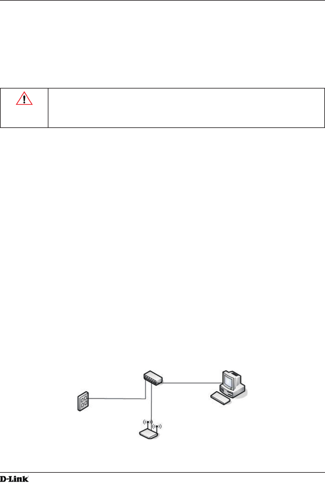
1.) Connect the AP to an administrative PC by using a LAN connection or a direct-cable connection.
•) To use a LAN connection, connect one end of an Ethernet cable to the network port on the access point and
the other end to the same hub where your PC is connected, as shown in the following gure.
The hub or switch you use must permit broadcast signals from the access point to reach all other devices on
the network.
Unied Access Point Administrator’s Guide
Unied Access Point Administrator’s Guide
Page 14
May 2016
Section 2 - Getting Started
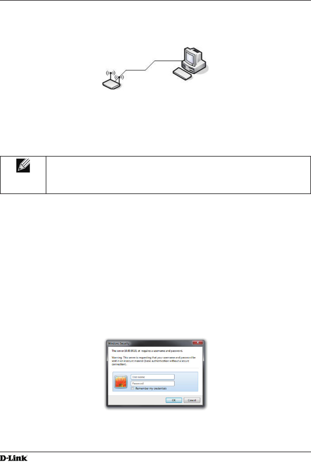
•) To use a direct-cable connection, connect one end of an Ethernet straight-through or crossover cable to the
network port on the access point and the other end of the cable to the Ethernet port on the PC, as shown in
the following gure. You can also use a serial cable to connect the serial port on the AP to a serial port on the
administrative computer.
For initial conguration with a direct Ethernet connection and no DHCP server, be sure to set your PC to a
static IP address in the same subnet as the default IP address on the access point. (The default IP address for
the access point is 10.90.90.91.)
If you use this method, you will need to recongure the cabling for subsequent startup and deployment of the
access point so that the access point is no longer connected directly to the PC but instead is connected to the
LAN (either by using a hub or directly).
Note: It is possible to detect access points on the network with a wireless connection. However,
we strongly advise against using this method. In most environments you may have no way
of knowing whether you are actually connecting to the intended AP. Also, many of the initial
conguration changes required will cause you to lose connectivity with the AP over a wireless
connection.
2.) Connect the power adapter to the power port on the back of the access point, and then plug the other end of the
power cord into a power outlet.
3.) Use your Web browser to log on to the UAP Administration Web pages.
•) If the AP did not acquire an IP address from a DHCP server on your network, enter 10.90.90.91 in the address
eld of your browser, which is the default IP address of the AP.
•) If you used a DHCP server on your network to automatically congure network information for the AP, enter the
new IP address of the AP into the Web browser.
•) If you used a DHCP server and you do not know the new IP address of the AP, use the following procedures to
obtain the information:
•) Connect a serial cable from the administrative computer to the AP and use a terminal emulation program to
access the command-line interface (CLI).
•) At the login prompt, enter admin for the user name and admin for the password. At the command prompt,
enter get management.
•) The command output displays the IP address of the AP. Enter this address in the address eld of your browser.
For a more detailed explanation about how to log on to the CLI by using the console port, see “Using the CLI
to View the IP Address” on page 24.
4.) When prompted, enter admin for the user name and admin for the password, then click Logon.
Figure 2 - Web UI Login Prompt
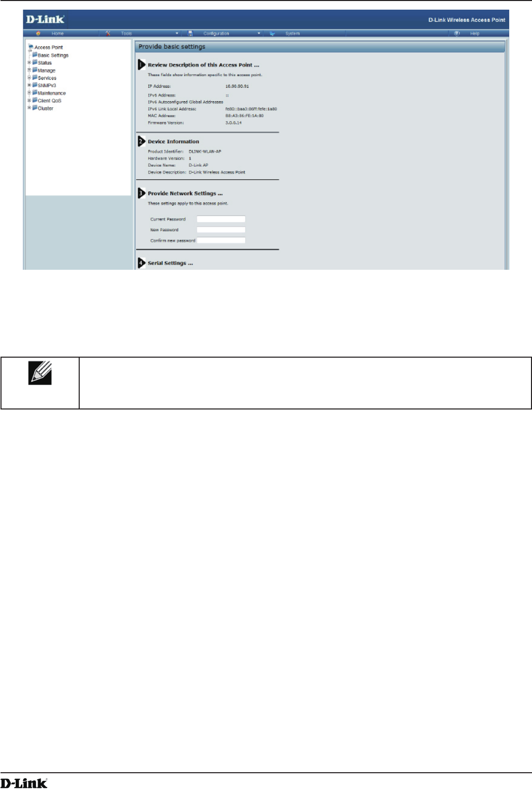
When you rst log in, the Basic Settings page for UAP administration is displayed, as the following gure
shows.
Unied Access Point Administrator’s Guide
Unied Access Point Administrator’s Guide
Page 15
May 2016
Section 2 - Getting Started
Figure 3 - Provide Basic Settings
5.) Verify the settings on the Basic Settings page.
•) Review access point description and provide a new administrator password for the access point if you do not
want to use the default password, which is admin.
•) Click the Apply button to activate the wireless network with these new settings.
Note: The changes you make are not saved or applied until you click Apply. Changing some
access point settings might cause the AP to stop and restart system processes. If this happens,
wireless clients will temporarily lose connectivity. We recommend that you change access point
settings when WLAN trafc is low.
For information about the elds and conguration options on the Basic Settings page, see “Basic Settings” on
page 16.
6.) If you do not have a DHCP server on the management network and do not plan to use one, you must change
the Connection Type from DHCP to Static IP.
You can either assign a new Static IP address to the AP or continue using the default address. We recommend
assigning a new Static IP address so that if you bring up another UAP on the same network, the IP address
for each AP will be unique. To change the connection type and assign a static IP address, see “Conguring the
Ethernet Settings” on page 18 (CLI) or “Ethernet Settings” on page 35 (Web).
7.) If your network uses VLANs, you might need to congure the management VLAN ID or untagged VLAN ID on
the UAP in order for it to work with your network.
For information about how to congure VLAN information, see “Conguring the Ethernet Settings” on page 18
(CLI) or “Ethernet Settings” on page 35 (Web).
8.) If your network uses IEEE 802.1X port security for network access control, you must congure the 802.1X
supplicant information on the AP.
For information about how to congure the 802.1X user name and password, see “Conguring IEEE 802.1X
Authentication” on page 19.

Unied Access Point Administrator’s Guide
Unied Access Point Administrator’s Guide
Page 16
May 2016
Section 2 - Getting Started
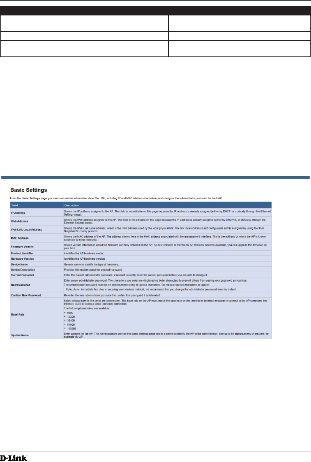
Basic Settings
From the Basic Settings page, you can view various information about the UAP, including IP and MAC address
information, and congure the administrator password for the UAP. The following table describes the elds and
conguration options on the Basic Settings page.
Field Description
IP Address Shows the IP address assigned to the AP. This eld is not editable on this page because
the IP address is already assigned (either by DHCP, or statically through the Ethernet
Settings page).
IPv6 Address Shows the IPv6 address assigned to the AP. This eld is not editable on this page because
the IP address is already assigned (either by DHCPv6, or statically through the Ethernet
Settings page).
IPv6 Address Status Shows the operational status of the static IPv6 address assigned to the management
interface of the AP. The possible values are Operational and Tentative.
IPv6 Autocongured
Global Addresses
Shows each automatically-congured global IPv6 address for the management interface of
the AP.
IPv6 Link Local
Address
Shows the IPv6 Link Local address, which is the IPv6 address used by the local physical
link. The link local address is not congurable and is assigned by using the IPv6 Neighbor
Discovery process.
MAC Address Shows the MAC address of the AP. The address shown here is the MAC address
associated with the management interface. This is the address by which the AP is known
externally to other networks.
Firmware Version Shows version information about the rmware currently installed on the AP. As new
versions of the WLAN AP rmware become available, you can upgrade the rmware on
your APs.
Product Identier Identies the AP hardware model.
Hardware Version Identies the AP hardware version.
Serial Number Shows the AP serial number.
Device Name Generic name to identify the type of hardware.
Device Description Provides information about the product hardware.
Current Password Enter the current administrator password. You must correctly enter the current password
before you are able to change it.
New Password Enter a new administrator password. The characters you enter are displayed as bullet
characters to prevent others from seeing your password as you type.
The administrator password must be an alphanumeric string of up to 8 characters. Do not
use special characters or spaces.
Note: As an immediate rst step in securing your wireless network, we recommend that
you change the administrator password from the default.
Conrm New
Password
Re-enter the new administrator password to conrm that you typed it as intended.
Baud Rate Select a baud rate for the serial port connection. The baud rate on the AP must match the
baud rate on the terminal or terminal emulator to connect to the AP command-line interface
(CLI) by using a serial (console) connection.
The following baud rates are available:
•) 9600
•) 19200
•) 38400
•) 57600
•) 115200
System Name Enter a name for the AP. This name appears only on the Basic Settings page and is a
name to identify the AP to the administrator. Use up to 64 alphanumeric characters, for
example My AP.

Unied Access Point Administrator’s Guide
Unied Access Point Administrator’s Guide
Page 17
May 2016
Section 2 - Getting Started
Field Description
System Contact Enter the name, e-mail address, or phone number of the person to contact regarding
issues related to the AP.
System Location Enter the physical location of the AP, for example Conference Room A.
Table 4 - Basic Settings Page
Connecting to the AP Web Interface by Using the IPv6 Address
To connect to the AP by using the IPv6 global address or IPv6 link local address, you must enter the AP address into
your browser in a special format.
Note: The following instructions and examples work with Microsoft Internet Explorer 7 (IE7) and
might not work with other browsers.
To connect to an IPv6 global address, add square brackets around the IPv6 address. For example, if the AP
global IPv6 address is 2520::230:abff:fe00:2420, type the following address into the IE7 address eld: http://
[2520::230:abff:fe00:2420].
To connect to the iPv6 link local address, replace the colons (:) with hyphens (-), add the interface number preceded
with an “s,” then add “.ipv6-literal.net.” For example, if the AP link local address is fe80::230:abff:fe00:2420, and the
Windows interface is dened as “%6,” type the following address into the IE7 address eld: http://fe80--230-abff-fe00-
2420s6.ipv6-literal.net.
Using the CLI to View the IP Address
The DHCP client on the UAP is enabled by default. If you connect the UAP to a network with a DHCP server, the
AP automatically acquires an IP address. To manage the UAP by using the Administrator UI, you must enter the IP
address of the access point into a Web browser.
If a DHCP server on your network assigns an IP address to the UAP, and you do not know the IP address, use the
following steps to view the IP address of the UAP:
1.) Using a null-modem cable, connect a VT100/ANSI terminal or a workstation to the console (serial) port.
If you attached a PC, Apple, or UNIX workstation, start a terminal-emulation program, such as HyperTerminal or
TeraTerm.
2.) Congure the terminal-emulation program to use the following settings:
•) Baud rate: 115200 bps
•) Data bits: 8
•) Parity: none
•) Stop bit: 1
•) Flow control: none
3.) Press the return key, and a login prompt should appear.
The login name is admin. The default password is admin. After a successful login, the screen shows the
(Access Point Name)# prompt.
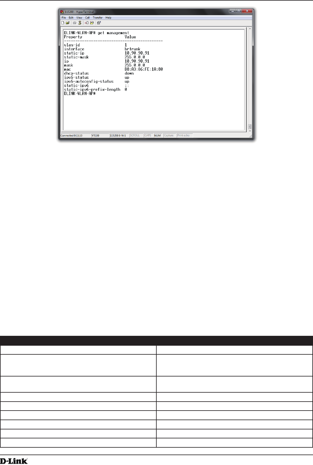
4.) At the login prompt, enter get management.
Information similar to the following prints to the screen.
Unied Access Point Administrator’s Guide
Unied Access Point Administrator’s Guide
Page 18
May 2016
Section 2 - Getting Started
Figure 4 - Command Line Interface (CLI) Connection
Conguring the Ethernet Settings
The default Ethernet settings, which include DHCP and VLAN information, might not work for all networks.
By default, the DHCP client on the UAP automatically broadcasts requests for network information. If you want to
use a static IP address, you must disable the DHCP client and manually congure the IP address and other network
information.
The management VLAN is VLAN 1 by default. This VLAN is also the default untagged VLAN. If you already have
a management VLAN congured on your network with a different VLAN ID, you must change the VLAN ID of the
management VLAN on the access point.
For information about using the Web interface to congure the Ethernet settings, see “Ethernet Settings” on page
35. You can also use the CLI to congure the Ethernet settings, which the following section describes.
Using the CLI to Congure Ethernet Settings
Use the commands shown in the following table to view and set values for the Ethernet (wired) interface. For more
information about each setting, see the description for the eld in the following table.
Action Commands
Get the DNS Name get host id
Set the DNS Name set host id <host_name>
For example:
set host id lab-ap
Get Current Settings for the Ethernet (Wired) Internal
Interface
get management
Set the management VLAN ID set management vlan-id <1-4094>
View untagged VLAN information get untagged-vlan
Enable the untagged VLAN set untagged-vlan status up
Disable the untagged VLAN set untagged-vlan status down
Set the untagged VLAN ID set untagged-vlan vlan-id <1-4094>
View the connection type get management dhcp-status

Unied Access Point Administrator’s Guide
Unied Access Point Administrator’s Guide
Page 19
May 2016
Section 2 - Getting Started
Action Commands
Use DHCP as the connection type set management dhcp-status up
Use a Static IP as the connection type set management dhcp-status down
Set the Static IP address set management static-ip <ip_address>
For example:
set management static-ip 10.10.12.221
Set a Subnet Mask set management static-mask <netmask>
For example:
set management static-mask 255.255.255.0
Set the Default Gateway set static-ip-route gateway <ip_address>
For example:
set static-ip-route gateway 10.10.12.1
View the DNS Nameserver mode Dynamic= up
Manual=down
get host dns-via-dhcp
Set DNS Nameservers to Use Static IP Addresses
(Dynamic to Manual Mode)
set host dns-via-dhcp down
set host static-dns-1 <ip_address>
set host static-dns-2 <ip_address>
For example:
set host static-dns-1 192.168.23.45
Set DNS Nameservers to Use DHCP IP Addressing
(Manual to Dynamic Mode)
set host dns-via-dhcp up
Table 5 - CLI Commands for Ethernet Setting
In the following example, the administrator uses the CLI to set the management VLAN ID to 123 and to disable the
untagged VLAN so that all trafc is tagged with a VLAN ID.
DLINK-WLAN-AP# set management vlan-id 123
DLINK-WLAN-AP# set untagged-vlan status down
DLINK-WLAN-AP# get management
Property Value
--------------------------------------------
vlan-id 123
interface brtrunk
static-ip 10.90.90.91
static-mask 255.0.0.0
ip 10.90.90.91
mask 255.0.0.0
mac 00:05:5E:80:70:00
dhcp-status down
ipv6-status up
ipv6-autocong-status up
static-ipv6 ::
static-ipv6-prex-length 0
DLINK-WLAN-AP# get untagged-vlan
Property Value
---------------
vlan-id 1
status down
DLINK-WLAN-AP#
Conguring IEEE 802.1X Authentication
On networks that use IEEE 802.1X, port-based network access control, a supplicant (client) cannot gain access to
the network until the 802.1X authenticator grants access. If your network uses 802.1X, you must congure 802.1X
authentication information that the AP can supply to the authenticator.
If your network uses IEEE 802.1X see “Conguring IEEE 802.1X Authentication” on page 19 for information about
how to congure 802.1X by using the Web interface.

Unied Access Point Administrator’s Guide
Unied Access Point Administrator’s Guide
Page 20
May 2016
Section 2 - Getting Started
Using the CLI to Congure 802.1X Authentication Information
The following table shows the commands used to congure the 802.1X supplicant information using the CLI.
Action Command
View 802.1X supplicant settings get dot1x-supplicant
Enable 802.1X supplicant set dot1x-supplicant status up
Disable 802.1X supplicant set dot1x-supplicant status down
Set the 802.1X user name set dot1x-supplicant user <name>
Set the 802.1X password set dot1x-supplicant password <password>
Table 6 - CLI Commands for the 802.1X Supplicant
In the following example, the administrator enables the 802.1X supplicant and sets the user name to wlanAP and the
password to test1234.
DLINK-WLAN-AP# set dot1x-supplicant status up
DLINK-WLAN-AP# set dot1x-supplicant user wlanAP
DLINK-WLAN-AP# set dot1x-supplicant password test1234
DLINK-WLAN-AP# get dot1x-supplicant
Property Value
--------------------------
status up
user wlanAP
eap-method md5
debug off
cert-present no
cert-exp-date Not Present
DLINK-WLAN-AP#
Verifying the Installation
Make sure the access point is connected to the LAN and associate some wireless clients with the network. Once you
have tested the basics of your wireless network, you can enable more security and ne-tune the AP by modifying
advanced conguration features.
1.) Connect the access point to the LAN.
•) If you congured the access point and administrator PC by connecting both into a network hub, then your
access point is already connected to the LAN. The next step is to test some wireless clients.
•) If you congured the access point by using a direct cable connection from your computer to the access point,
do the following procedures:
•) Disconnect the cable from the computer and the access point.
•) Connect an Ethernet cable from the access point to the LAN.
•) Connect your computer to the LAN by using an Ethernet cable or a wireless card.
2.) Test LAN connectivity with wireless clients.
Test the UAP by trying to detect it and associate with it from some wireless client devices. For information about
requirements for these clients, see “Wireless Client Requirements” on page 12.
3.) Secure and congure the access point by using advanced features.
Once the wireless network is up and you can connect to the AP with some wireless clients, you can add in layers
of security, create multiple virtual access points (VAPs), and congure performance settings.
Note: The WLAN AP is not designed for multiple, simultaneous conguration changes. If more
than one administrator is logged onto the Administration Web pages and making changes to the
conguration, there is no guarantee that all conguration changes specied by multiple users will
be applied.
By default, no security is in place on the access point, so any wireless client can associate with it and access
your LAN. An important next step is to congure security, as described in “Virtual Access Point Settings” on page
47.

Unied Access Point Administrator’s Guide
Unied Access Point Administrator’s Guide
Page 21
May 2016
Section 2 - Getting Started
Conguring Security on the Wireless Access Point
You congure secure wireless client access by conguring security for each virtual access point (VAP) that you
enable. You can congure up to 16 VAPs per radio that simulate multiple APs in one physical access point. By default,
only one VAP is enabled. For each VAP, you can congure a unique security mode to control wireless client access.
Each radio has 16 VAPs, with VAP IDs from 0-15. By default, only VAP 0 on each radio is enabled. VAP0 has the
following default settings:
•) VLAN ID: 1
•) Broadcast SSID: Enabled
•) SSID: dlink1
•) Security: None
•) MAC Authentication Type: None
•) Redirect Mode: None
All other VAPs are disabled by default. The default SSID for VAPs 1–15 is ”dlinkx” where x is the VAP ID.
To prevent unauthorized access to the UAP, we recommend that you select and congure a security option other than
None for the default VAP and for each VAP that you enable.
For information about how to congure the security settings on each VAP, see “Virtual Access Point Settings” on page
47.
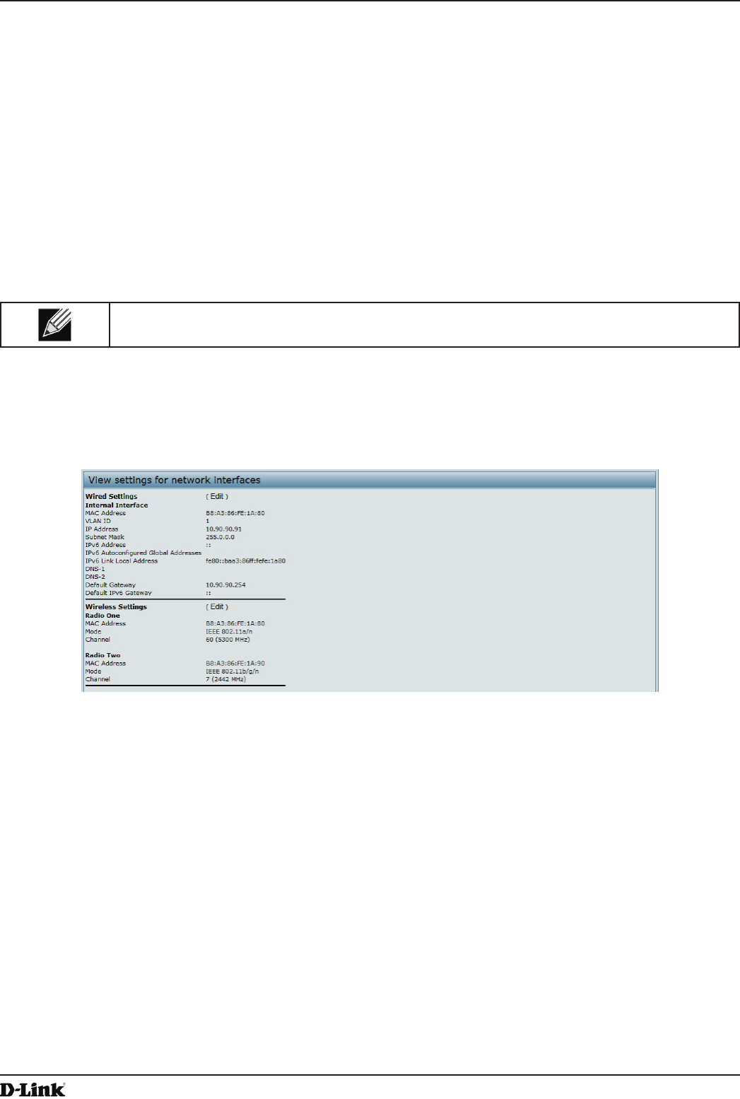
Unied Access Point Administrator’s Guide
Unied Access Point Administrator’s Guide
Page 22
May 2016
Section 3 - Viewing Access Point Status
Section 3 - Viewing Access Point Status
This section describes the information you can view from the tabs under the Status heading on the Administration
Web UI. This section contains the following subsections:
•) “Viewing Interface Status” on page 22
•) “Viewing Events” on page 23
•) “Viewing Transmit and Receive Statistics” on page 25
•) “Viewing Associated Wireless Client Information” on page 26
•) “Viewing TSPEC Client Associations” on page 26
•) “Viewing Rogue AP Detection” on page 28
•) “Viewing Managed AP DHCP Information” on page 31
•) “Viewing TSPEC Status and Statistics Information” on page 31
•) “Viewing TSPEC AP Statistics Information” on page 32
•) “Viewing Radio Statistics Information” on page 33
•) “Viewing Email Alert Operational Status” on page 34
Note: The web-based UI images show the DWL-8600AP administration pages. Pages for the
DWL-2600AP or DWL-3600AP will display information for one radio only.
Viewing Interface Status
To monitor Ethernet LAN (wired) and wireless LAN (WLAN) settings, click the Interfaces tab.
Figure 5 - Viewing Interface Status
This page displays the current settings of the UAP. It displays the Wired Settings and the Wireless Settings.
Wired Settings (Internal Interface)
The Internal interface includes the Ethernet MAC Address, Management VLAN ID, IP Address (IPv4 and IPv6),
Subnet Mask, and DNS information. To change any of these settings, click the Edit link. After you click Edit, you are
redirected to the Ethernet Settings page.
For information about conguring these settings, see “Conguring the Ethernet Settings” on page 18.
Wireless Settings
The Radio Interface includes the AeroScout™ Engine Communication status, Radio Mode and Channel. The
Wireless Settings section also shows the MAC address (read-only) associated with each radio interface.
To change the Radio Mode or Channel settings, click the Edit link. After you click Edit, you are redirected to the
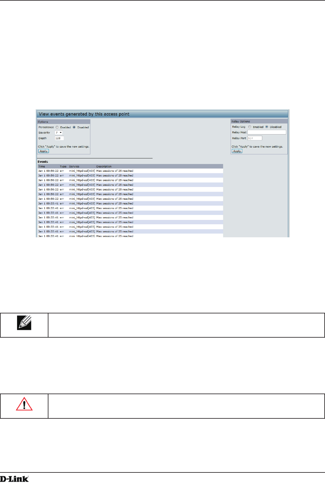
Unied Access Point Administrator’s Guide
Unied Access Point Administrator’s Guide
Page 23
May 2016
Section 3 - Viewing Access Point Status
Modify Wireless Settings page.
For information about conguring these settings, see “Wireless Settings” on page 37 and “Modifying Radio Settings”
on page 40.
Viewing Events
The Events page shows real-time system events on the AP such as wireless clients associating with the AP and being
authenticated.
To view system events, click the Events tab.
Figure 6 - Viewing Events
From the Events page, you can perform the following tasks:
•) View the most recent, high-level events generated by this AP.
•) Enable and congure Persistent logging to write system event logs to non-volatile memory so that the events
are not erased when the system reboots.
•) Set a Severity Level to determine what category of log messages are displayed.
•) Set Depth to determine how many log messages are displayed in the Event log.
•) Enable a remote log relay host to capture all system events and errors in a Kernel Log.
Note: The AP acquires its date and time information using the network time protocol (NTP). This
data is reported in UTC format (also known as Greenwich Mean Time). You need to convert the
reported time to your local time.
Conguring Persistent Logging Options
If the system unexpectedly reboots, log messages can be useful to diagnose the cause. However, log messages are
erased when the system reboots unless you enable persistent logging.
Caution! Enabling persistent logging can wear out the ash (non-volatile) memory and degrade
network performance. You should only enable persistent logging to debug a problem. Make sure
you disable persistent logging after you nish debugging the problem.
To congure persistent logging on the Events page, set the persistence, severity, and depth options as described in
the following table, and then click Apply.
Unied Access Point Administrator’s Guide
Unied Access Point Administrator’s Guide
Page 24
May 2016
Section 3 - Viewing Access Point Status
Field Description
Persistence Choose Enabled to save system logs to non-volatile memory so that the logs are not erased
when the AP reboots. Choose Disabled to save system logs to volatile memory. Logs in
volatile memory are deleted when the system reboots.
Severity Specify the severity level of the log messages to write to non-volatile memory. For example,
if you specify 2, critical, alert, and emergency logs are written to non-volatile memory. Error
messages with a severity level of 3 – 7 are written to volatile memory.
•) 0 — emergency
•) 1 — alert
•) 2 — critical
•) 3 — error
•) 4 — warning
•) 5 — notice
•) 6 — info
•) 7 — debug
Depth You can store up to 128 messages in non-volatile memory. Once the number you congure
in this eld is reached, the oldest log event is overwritten by the new log event.
Table 7 - Logging Options
Note: To apply your changes, click Apply. Changing some settings might cause the AP to stop
and restart system processes. If this happens, wireless clients will temporarily lose connectivity.
We recommend that you change AP settings when WLAN trafc is low.
Conguring the Log Relay Host for Kernel Messages
The Kernel Log is a comprehensive list of system events (shown in the System Log) and kernel messages such as
error conditions, like dropping frames.
You cannot view kernel log messages directly from the Administration Web UI for an AP. You must rst set up a remote
server running a syslog process and acting as a syslog log relay host on your network. Then, you can congure the
UAP to send syslog messages to the remote server.
Remote log server collection for AP syslog messages provides the following features:
•) Allows aggregation of syslog messages from multiple APs
•) Stores a longer history of messages than kept on a single AP
•) Triggers scripted management operations and alerts
To use Kernel Log relaying, you must congure a remote server to receive the syslog messages. The procedure to
congure a remote log host depends on the type of system you use as the remote host.
Note: The syslog process will default to use port 514. We recommend keeping this default port.
However; If you choose to recongure the log port, make sure that the port number you assign to
syslog is not being used by another process.
Enabling or Disabling the Log Relay Host on the Events Page
To enable and congure Log Relaying on the Events page, set the Log Relay options as described in the following
table, and then click Apply.
Field Description
Relay Log Select Enabled to allow the UAP to send log messages to a remote host. Select Disabled
to keep all log messages on the local system.
Relay Host Specify the IP Address or DNS name of the remote log server.
Relay Port Specify the Port number for the syslog process on the Relay Host.
The default port is 514.
Table 8 - Log Relay Host
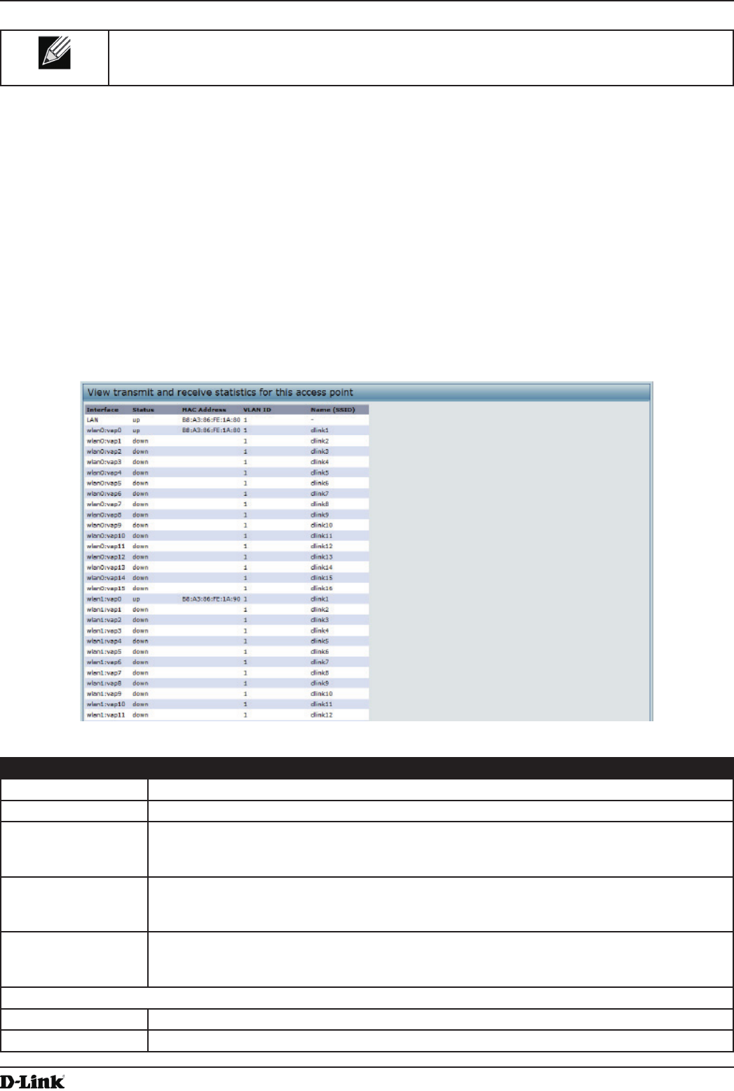
Unied Access Point Administrator’s Guide
Unied Access Point Administrator’s Guide
Page 25
May 2016
Section 3 - Viewing Access Point Status
Note: To apply your changes, click Apply. Changing some settings might cause the AP to stop
and restart system processes. If this happens, wireless clients will temporarily lose connectivity.
We recommend that you change AP settings when WLAN trafc is low.
If you enabled the Log Relay Host, clicking Apply will activate remote logging. The AP will send its kernel messages
real-time for display to the remote log server monitor, a specied kernel log le, or other storage, depending on how
you congured the Log Relay Host.
If you disabled the Log Relay Host, clicking Apply will disable remote logging.
Viewing Transmit and Receive Statistics
The Transmit/Receive page provides some basic information about the current AP and a real-time display of the
transmit and receive statistics for the Ethernet interface on the AP and for the VAPs on all supported radio interfaces.
All transmit and receive statistics shown are totals since the AP was last started. If you reboot the AP, these gures
indicate transmit and receive totals since the reboot.
To view transmit and receive statistics for the AP, click the Transmit/Receive page.
Figure 7 - Viewing Trafc Statistics
Field Description
Interface The name of the Ethernet or VAP interface.
Status Shows whether the interface is up or down.
MAC Address MAC address for the specied interface. The UAP has a unique MAC address for each
interface. Each radio has a different MAC address for each interface on each of its two
radios.
VLAN ID Virtual LAN (VLAN) ID.
You can use VLANs to establish multiple internal and guest networks on the same AP.
The VLAN ID is set on the VAP page. (See “Conguring Load Balancing” on page 60)
Name (SSID) Wireless network name. Also known as the SSID, this alphanumeric key uniquely identies a
wireless local area network.
The SSID is set on the VAP page. (See “Conguring Load Balancing” on page 60)
Transmit and Receive Information
Total Packets Indicates total packets sent (in Transmit table) or received (in Received table) by this AP.
Total Bytes Indicates total bytes sent (in Transmit table) or received (in Received table) by this AP.
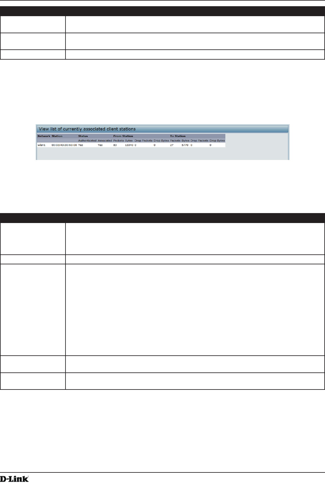
Unied Access Point Administrator’s Guide
Unied Access Point Administrator’s Guide
Page 26
May 2016
Section 3 - Viewing Access Point Status
Field Description
Total Drop Packets Indicates total number of packets sent (in Transmit table) or received (in Received table) by
this AP that were dropped.
Total Drop Bytes Indicates total number of bytes sent (in Transmit table) or received (in Received table) by
this AP that were dropped.
Errors Indicates total errors related to sending and receiving data on this AP.
Table 9 - Transmit/Receive
Viewing Associated Wireless Client Information
To view the client stations associated with a particular access point, click the Client Associations tab.
Figure 8 - Viewing Client Association Information
The associated stations are displayed along with information about packet trafc transmitted and received for each
station.
The following describes the elds on the Client Associations page.
Field Description
Network Shows which VAP the client is associated with. For example, an entry of wlan0vap2 means
the client is associated with Radio 1, VAP 2.
An entry of wlan0 means the client is associated with VAP 0 on Radio 1. An entry of wlan1
means the client is associated with VAP 0 on Radio 2.
Station Shows the MAC address of the associated wireless client.
Status The Authenticated and Associated Status shows the underlying IEEE 802.11 authentication
and association status, which is present no matter which type of security the client uses to
connect to the AP. This status does not show IEEE 802.1X authentication or association
status.
Some points to keep in mind with regard to this eld are:
•) If the AP security mode is None or Static WEP, the authentication and association
status of clients showing on the Client Associations page will be in line with what is
expected; that is, if a client shows as authenticated to the AP, it will be able to transmit
and receive data. (This is because Static WEP uses only IEEE 802.11 authentication.)
•) If the AP uses IEEE 802.1X or WPA security, however, it is possible for a client
association to show on this page as authenticated (via the IEEE 802.11 security) but
actually not be authenticated to the AP via the second layer of security.
From Station Shows the number of packets and bytes received from the wireless client and the number of
packets and bytes that were dropped after being received.
To Station Shows the number of packets and bytes transmitted from the AP to the wireless client and
the number of packets and bytes that were dropped upon transmission.
Table 10 - Associated Clients
Viewing TSPEC Client Associations
The TSPEC Client Association Status and Statistics page provides some basic information about the client
associations status and a real-time display of the transmit and receive statistics for the TSPEC clients. All transmit and
receive statistics shown are totals since the client association started.
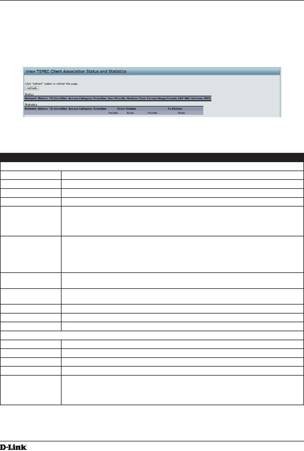
Unied Access Point Administrator’s Guide
Unied Access Point Administrator’s Guide
Page 27
May 2016
Section 3 - Viewing Access Point Status
A TSPEC is a trafc specication that is sent from a QoS-capable wireless client to an AP requesting a certain
amount of network access for the trafc stream (TS) it represents. A trafc stream is a collection of data packets
identied by the wireless client as belonging to a particular user priority. An example of a voice trafc stream is a Wi-Fi
CERTIFIED™ telephone handset that marks its codec-generated data packets as voice priority trafc. An example of
a video trafc stream is a video player application on a wireless laptop that prioritizes a video conference feed from a
corporate server.
To view TSPEC client association statistics, click the TSPEC Client Associations tab.
Figure 9 - Viewing TSPEC Client Associations
The following table describes the information provided on the TSPEC Client Association Status and Statistics
page.
Field Description
Status
Network Radio interface used by the client.
Station Client station MAC address.
TS Identier TSPEC Trafc Session Identier (range 0-7).
Access Category TS Access Category (voice or video).
Direction The trafc direction for this TS. Direction can be:
•) uplink
•) downlink
•) bidirectional
User Priority The User Priority (UP) for this TS. The UP is sent with each packet in the UP portion of the
IP header. Typical values are:
•) 6 or 7 for voice
•) 4 or 5 for video
The value may differ depending on other priority trafc sessions.
Medium Time The time (in 32 microsecond per second units) that the TS trafc occupies the transmission
medium.
Excess Usage
Events
The number of times the client has exceeded the medium time established for its TSPEC.
Minor, infrequent violations are ignored.
VAP The Virtual Access Point associated with this TS client.
MAC Address The Virtual Access Point MAC address.
SSID The service set identier associated with this TS client.
Statistics
Network Radio interface used by the client.
Station Client station MAC address.
TS Identier TSPEC Trafc Session Identier (range 0-7).
Access Category TS Access Category (voice or video).
Direction The trafc direction for this TS. Direction can be:
•) uplink
•) downlink
•) bidirectional
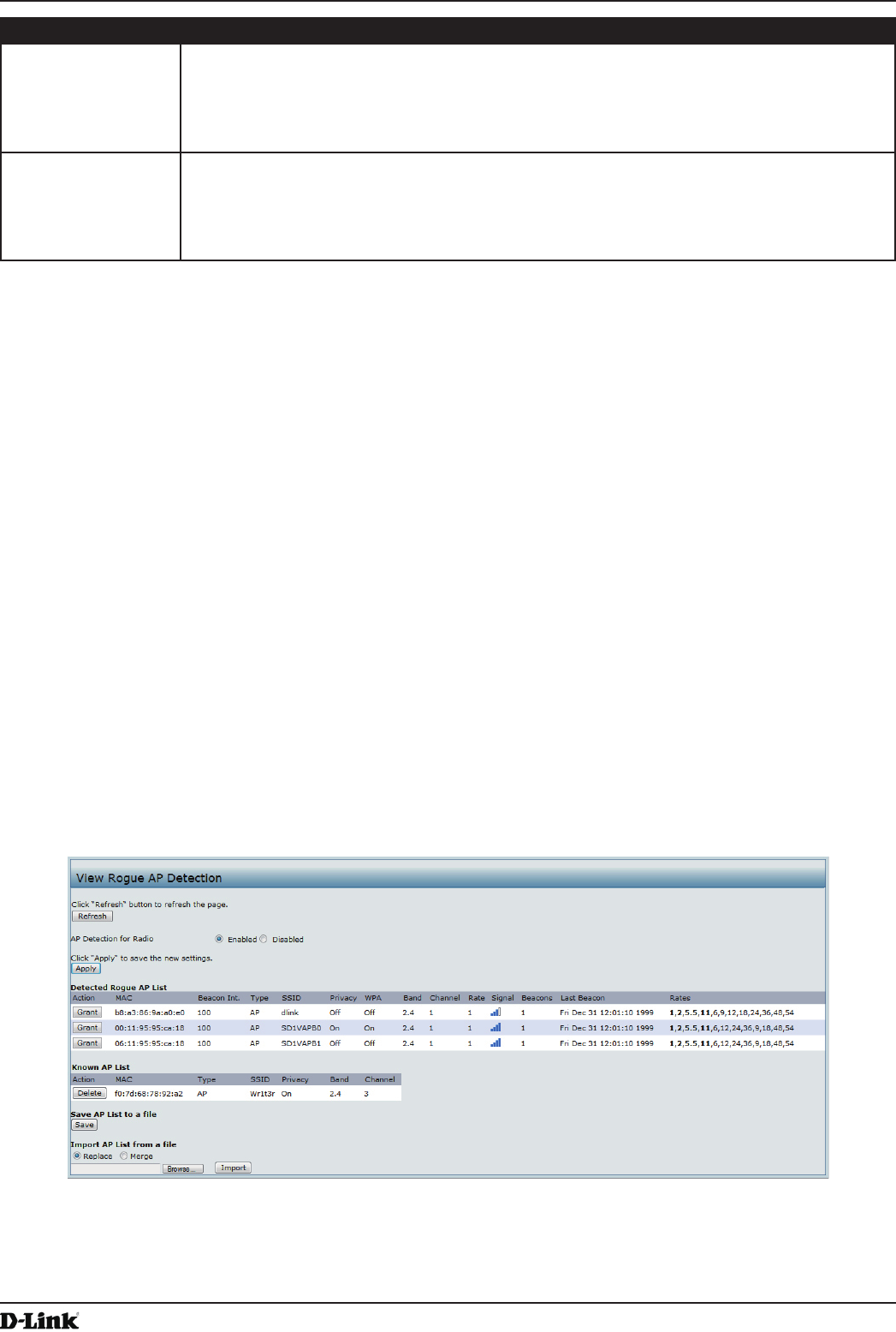
Unied Access Point Administrator’s Guide
Unied Access Point Administrator’s Guide
Page 28
May 2016
Section 3 - Viewing Access Point Status
Field Description
From Station Shows the number of packets and bytes received from the wireless client and the number
of packets and bytes that were dropped after being received. Also shows the number of
packets:
•) in excess of an admitted TSPEC.
•) for which no TSPEC has been established when admission is required by the AP.
To Station Shows the number of packets and bytes transmitted from the AP to the wireless client and
the number of packets and bytes that were dropped upon transmission. Also shows the
number of packets:
•) in excess of an admitted TSPEC.
•) for which no TSPEC has been established when admission is required by the AP.
Table 11 - TSPEC Client Associations
Link Integrity Monitoring
The UAP provides link integrity monitoring to continually verify its connection to each associated client. To do this,
the AP sends data packets to clients every few seconds when no other trafc is passing. This allows the AP to detect
when a client goes out of range, even during periods when no normal trafc is exchanged. The client connection
drops off the list within 300 seconds if these data packets are not acknowledged, even if no disassociation message is
received.
Viewing Rogue AP Detection
The status page to view Rogue AP Detection information provides real-time statistics for all APs within range of the
AP on which you are viewing the Administration Web pages. When AP detection is enabled, the radio will periodically
switch from its operating channel to scan other channels within the same band. Click Refresh to update the screen
and display the most current information.
The Rogue AP Detection page contains the following two lists:
•) Detected Rogue AP List — Lists all APs within range of the AP that have not been acknowledged as known APs.
•) Known AP List — Lists all APs within range of the AP that have been acknowledged as known APs either by
clicking the Grant button associated with an AP in the Detected Rogue AP List or by appearing in an imported
AP list.
To view information about other access points on the wireless network, click the Rogue AP Detection tab.
Figure 10 - Viewing Rogue and Known Access Points
You must enable the AP detection on a radio in order to collect information about other APs within range.
The following table describes the information provided on neighboring access points.

Unied Access Point Administrator’s Guide
Unied Access Point Administrator’s Guide
Page 29
May 2016
Section 3 - Viewing Access Point Status
Field Description
AP Detection for
Radio
To allow the AP radios to perform neighbor AP detection and collect information about
neighbor APs, click Enabled.
To disable neighbor AP detection on the radios, click Disabled.
If you change the AP detection mode, click Apply to save the new settings.
Detected Rogue AP List
Action Click Grant to move the AP from the Detected Rogue AP List to the Known AP List.
Note: The Detected Rouge AP and Known AP lists provide information. The DWL-x600AP
does not have any control over the APs on the list and cannot apply any security policies to
APs detected through the RF scan.
MAC Shows the MAC address of the neighboring AP.
Radio The Radio eld indicates which radio detected the neighboring AP:
•) wlan0 (Radio One)
•) wlan1 (Radio Two)
Beacon Int. Shows the Beacon interval being used by this AP.
Beacon frames are transmitted by an AP at regular intervals to announce the existence
of the wireless network. The default behavior is to send a beacon frame once every 100
milliseconds (or 10 per second).
The Beacon Interval is set on the Radio page.(See “Modifying Radio Settings” on page
40)
Type Indicates the type of device:
•) AP indicates the neighboring device is an AP that supports the IEEE 802.11 Wireless
Networking Framework in Infrastructure Mode.
•) Ad hoc indicates a neighboring station running in Ad hoc Mode. Stations set to ad
hoc mode communicate with each other directly, without the use of a traditional AP.
Ad-hoc mode is an IEEE 802.11 Wireless Networking Framework also referred to as
peer-to-peer mode or an Independent Basic Service Set (IBSS).
SSID The Service Set Identier (SSID) for the AP.
The SSID is an alphanumeric string of up to 32 characters that uniquely identies a wireless
local area network. It is also referred to as the Network Name.
The SSID is set on the VAP page. (See “Conguring Load Balancing” on page 60)
Privacy Indicates whether there is any security on the neighboring device.
•) Off indicates that the Security mode on the neighboring device is set to None (no
security).
•) On indicates that the neighboring device has some security in place.
•) Security is congured on the AP from the VAP page.
WPA Indicates whether WPA security is on or off for this AP.
Band This indicates the IEEE 802.11 mode being used on this AP. (For example, IEEE 802.11a,
IEEE 802.11b, IEEE 802.11g.)
The number shown indicates the mode according to the following map:
•) 2.4 indicates IEEE 802.11b, 802.11g, or 802.11n mode (or a combination of the modes)
•) 5 indicates IEEE 802.11a or 802.11n mode (or both modes)
Channel Shows the Channel on which the AP is currently broadcasting.
The channel denes the portion of the radio spectrum that the radio uses for transmitting
and receiving.
The channel is set in Radio Settings. (See “Modifying Radio Settings” on page 40)
Rate Shows the rate (in megabits per second) at which this AP is currently transmitting.
The current rate will always be one of the rates shown in Supported Rates.
Signal Indicates the strength of the radio signal emitting from this AP. If you hover the mouse
pointer over the bars, a number appears and shows the strength in decibels (dB).
Beacons Shows the total number of beacons received from this AP since it was rst discovered.
Last Beacon Shows the date and time of the last beacon received from this AP.
Rates Shows supported and basic (advertised) rate sets for the neighboring AP. Rates are shown
in megabits per second (Mbps).
All Supported Rates are listed, with Basic Rates shown in bold.
Rate sets are congured on the Radio Settings page. (See “Modifying Radio Settings” on
page 40)

Unied Access Point Administrator’s Guide
Unied Access Point Administrator’s Guide
Page 30
May 2016
Section 3 - Viewing Access Point Status
Field Description
Known AP List
Action An AP can appear in the Known AP List if it has been moved from the Detected Rogue AP
List by clicking the Grant button or if the MAC address of the AP appears in an AP list that
has been imported.
To move the AP from the Known AP List to the Detected Rogue AP List, click Delete.
Note: The Detected Rouge AP and Known AP lists provide information. The DWL-x600AP
does not have any control over the APs on the list and cannot apply any security policies to
APs detected through the RF scan.
MAC Shows the MAC address of the neighboring AP.
Type Indicates the type of device:
•) AP indicates the neighboring device is an AP that supports the IEEE 802.11 Wireless
Networking Framework in Infrastructure Mode.
•) Ad hoc indicates a neighboring station running in Ad hoc Mode. Stations set to ad
hoc mode communicate with each other directly, without the use of a traditional AP.
Ad-hoc mode is an IEEE 802.11 Wireless Networking Framework also referred to as
peer-to-peer mode or an Independent Basic Service Set (IBSS).
SSID The Service Set Identier (SSID) for the AP.
The SSID is an alphanumeric string of up to 32 characters that uniquely identies a wireless
local area network. It is also referred to as the Network Name.
The SSID is set on the VAP page. (See “Conguring Load Balancing” on page 60)
Privacy Indicates whether there is any security on the neighboring device.
•) Off indicates that the Security mode on the neighboring device is set to None (no
security).
•) On indicates that the neighboring device has some security in place.
•) Security is congured on the AP from the VAP page.
Band This indicates the IEEE 802.11 mode being used on this AP. (For example, IEEE 802.11a,
IEEE 802.11b, IEEE 802.11g.)
The number shown indicates the mode according to the following map:
•) 2.4 indicates IEEE 802.11b, 802.11g, or 802.11n mode (or a combination of the modes)
•) 5 indicates IEEE 802.11a or 802.11n mode (or both modes)
Channel Shows the Channel on which the AP is currently broadcasting.
The channel denes the portion of the radio spectrum that the radio uses for transmitting
and receiving.
The channel is set in Radio Settings. (See “Modifying Radio Settings” on page 40)
Table 12 - Rogue AP Detection
Saving and Importing the Known AP List
To save the Known AP list to a le, click Save. The list contains the MAC addresses of all AP that have been added to
the Known AP List. By default, the lename is Rogue1.cfg. You can use a text editor or Web browser to open the le
and view its contents.
Use the Import feature to import a list of Known APs from a saved list. The list might be from another DWL-x600AP or
created from a text le. If the MAC address of an AP appears in the Known AP List, it will not be detected as a rogue.
To import an AP List from a le, use the following steps:
1.) Choose whether to replace the existing Known AP list or add the entries in the imported le to the Known AP list.
•) Select the Replace option to import the list and replace the contents of the Known AP List.
•) Select the Merge option to import the list and add the APs in the imported le to the APs currently displayed in
the Known AP List.
2.) Click Browse and choose the le to import.
•) The le you import must be a plain-text le with a .txt or .cfg extension. Entries in the le are MAC addresses
in hexadecimal format with each octet separated by colons, for example 00:11:22:33:44:55. Separate entries
with a single space. For the AP to accept the le, it must contain only MAC addresses.
3.) Click Import.
•) Once the import is complete, the screen refreshes and the MAC addresses of the APs in the imported le
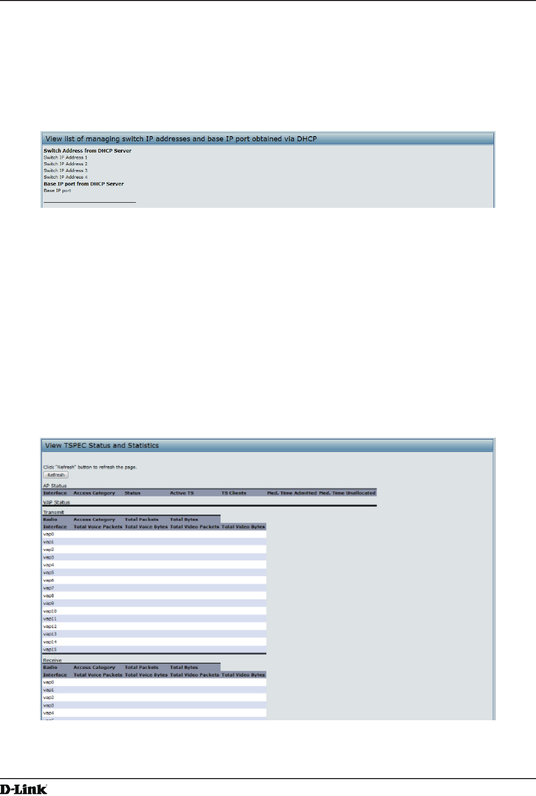
Unied Access Point Administrator’s Guide
Unied Access Point Administrator’s Guide
Page 31
May 2016
Section 3 - Viewing Access Point Status
appear in the Known AP List.
Viewing Managed AP DHCP Information
The UAP can learn about D-Link Unied Wireless Switches on the network through DHCP responses to its initial
DHCP request. The Managed AP DHCP page displays the DNS names or IP addresses of up to four D-Link Unied
Wireless Switches that the AP learned about from a DHCP server on your network.
Figure 11 - Managed AP DHCP Information
For information about how to congure a DHCP server to respond to AP DHCP requests with the switch IP address
information, see the User Manual for the switch.
Viewing TSPEC Status and Statistics Information
The TSPEC Status and Statistics page provides:
•) Summary information about TSPEC sessions by radio
•) Summary information about TSPEC sessions by VAP
•) Real-time transmit and receive statistics for the TSPEC VAPs on all radio interfaces.
All of the transmit and receive statistics shown are totals since the AP was last started. If you reboot the AP, these
gures indicate transmit and receive totals since the reboot.
To view TSPEC status and statistics, click the TSPEC Status and Statistics tab.
Figure 12 - Viewing TSPEC Status and Statistics
The following table describes the information provided on TSPEC Status and Statistics page.
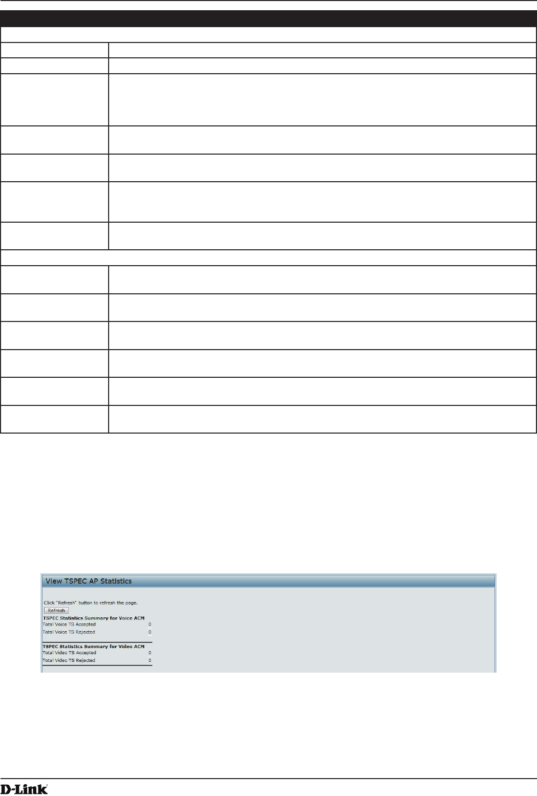
Unied Access Point Administrator’s Guide
Unied Access Point Administrator’s Guide
Page 32
May 2016
Section 3 - Viewing Access Point Status
Field Description
AP and VAP Status
Interface Indicates the name of the Radio or VAP interface.
Access Category Indicates Current Access Category associated with this Trafc Stream (voice or video).
Status Indicates whether the TSPEC session is enabled (up) or not (down) for the corresponding
Access Category.
Note: This is a conguration status (does not necessarily represent the current session
activity).
Active TS Indicates the number of currently active TSPEC Trafc Streams for this radio and Access
Category.
TS Clients Indicates the number of Trafc Stream clients associated with this radio and Access
Category.
Medium Time
Admitted
Time (in 32 microsecond per second units) allocated for this Access Category over the
transmission medium to carry data. This value should be less than or equal to the maximum
bandwidth allowed over the medium for this TS.
Medium Time
Unallocated
Time (in 32 microsecond per second units) of unused bandwidth for this Access Category.
Transmit and Receive Statistics
Total Packets Indicates the total number of TS packets sent (in Transmit table) or received (in Received
table) by this Radio for the specied Access Category.
Total Bytes Indicates the total number of TS bytes sent (in Transmit table) or received (in Received
table) by this Radio for the specied Access Category.
Total Voice Packets Indicates the total number of TS voice packets sent (in Transmit table) or received (in
Received table) by this AP for this VAP.
Total Voice Bytes Indicates the total TS voice bytes sent (in Transmit table) or received (in Received table) by
this AP for this VAP.
Total Video Packets Indicates the total number of TS video packets sent (in Transmit table) or received (in
Received table) by this AP for this VAP.
Total Video Bytes Indicates the total TS video bytes sent (in Transmit table) or received (in Received table) by
this AP for this VAP.
Table 13 - TSPEC Status and Statistics
Viewing TSPEC AP Statistics Information
The View TSPEC AP Statistics page provides information on the voice and video Trafc Streams accepted and
rejected by the AP.
To view TSPEC AP statistics, click the TSPEC AP Statistics tab.
Figure 13 - View TSPEC Status and Statistics
The following table describes the information provided on TSPEC AP Statistics page.
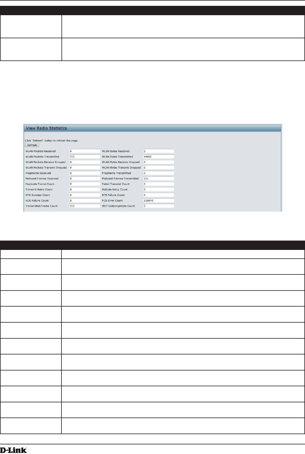
Unied Access Point Administrator’s Guide
Unied Access Point Administrator’s Guide
Page 33
May 2016
Section 3 - Viewing Access Point Status
Field Description
TSPEC Statistics
Summary for Voice
ACM
Indicates the total number of accepted and the total number of rejected voice Trafc
Streams.
TSPEC Statistics
Summary for Video
ACM
Indicates the total number of accepted and the total number of rejected video Trafc
Streams.
Table 14 - TSPEC AP Statistics
Viewing Radio Statistics Information
The Radio Statistics page provides detailed information about the packets and bytes transmitted and received on the
radio interface of this access point.
Figure 14 - View Radio Statistics
The following table describes details about the Radio Statistics information.
Field Description
Radio Choose either radio 1 or radio 2 to view statistics for the selected radio
WLAN Packets
Received
Total packets received by the AP on this radio interface.
WLAN Bytes
Received
Total bytes received by the AP on this radio interface.
WLAN Packets
Transmitted
Total packets transmitted by the AP on this radio interface.
WLAN Bytes
Transmitted
Total bytes transmitted by the AP on this radio interface.
WLAN Packets
Receive Dropped
Number of packets received by the AP on this radio interface that were dropped.
WLAN Bytes
Receive Dropped
Number of bytes received by the AP on this radio interface that were dropped.
WLAN Packets
Transmit Dropped
Number of packets transmitted by the AP on this radio interface that were dropped.
WLAN Bytes
Transmit Dropped
Number of bytes transmitted by the AP on this radio interface that were dropped.
Fragments
Received
Count of successfully received MPDU frames of type data or management.
Fragments
Transmitted
Number of transmitted MPDU with an individual address or an MPDU with a multicast
address of type Data or Management.
Multicast Frames
Received
Count of MSDU frames received with the multicast bit set in the destination MAC address.
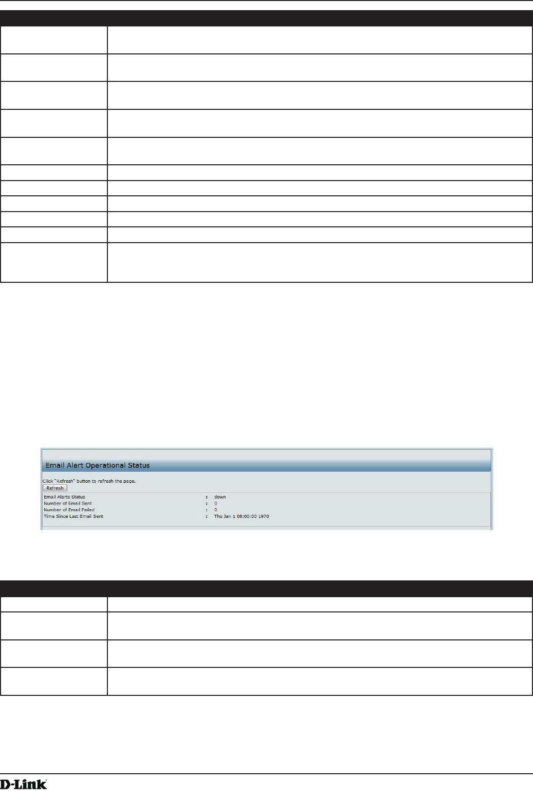
Unied Access Point Administrator’s Guide
Unied Access Point Administrator’s Guide
Page 34
May 2016
Section 3 - Viewing Access Point Status
Field Description
Multicast Frames
Transmitted
Count of successfully transmitted MSDU frames where the multicast bit is set in the
destination MAC address.
Duplicate Frame
Count
Number of times a frame is received and the Sequence Control eld indicates is a duplicate.
Failed Transmit
Count
Number of times an MSDU is not transmitted successfully due to transmit attempts
exceeding either the short retry limit or the long retry limit.
Transmit Retry
Count
Number of times an MSDU is successfully transmitted after one or more retries.
Multiple Retry
Count
Number of times an MSDU is successfully transmitted after more than one retry.
RTS Success Count Count of CTS frames received in response to an RTS frame.
RTS Failure Count Count of CTS frames not received in response to an RTS frame.
ACK Failure Count Count of ACK frames not received when expected.
FCS Error Count Count of FCS errors detected in a received MPDU frame.
Frames Transmitted Count of each successfully transmitted MSDU.
WEP Undecryptable
Count
Count of encrypted frames received and the key conguration of the transmitter indicates
that the frame should not have been encrypted or that frame was discarded due to the
receiving station not implementing the privacy option.
Table 15 - Radio Statistics Information
Viewing Email Alert Operational Status
The Email Alert Operational Status page provides information about the email alerts sent based on the syslog
messages generated in the AP.
To view the Email Alert Operational Status, click the Status > Email Alert Status tab.
To congure the email alerts, see “Conguring Email Alert” on page 72.
Figure 15 - Email Alert Operational Status
The following table describes details about the Email Alert Operational Status.
Field Description
Email Alert Status The Email Alert operational status The status is either Up or Down. The default is Down.
Number of Email
Sent
The total number of email sent so far. The range is an unsigned integer of 32 bits. The
default is 0.
Number of Email
Failed
The total number of email failures so far. The range is an unsigned integer of 32 bits. The
default is 0.
Time Since Last
Email Sent
The time since the last email was sent. Time format is used. The default is 00 days 00 hours
00 minutes 00 seconds.
Table 16 - Email Alert Status
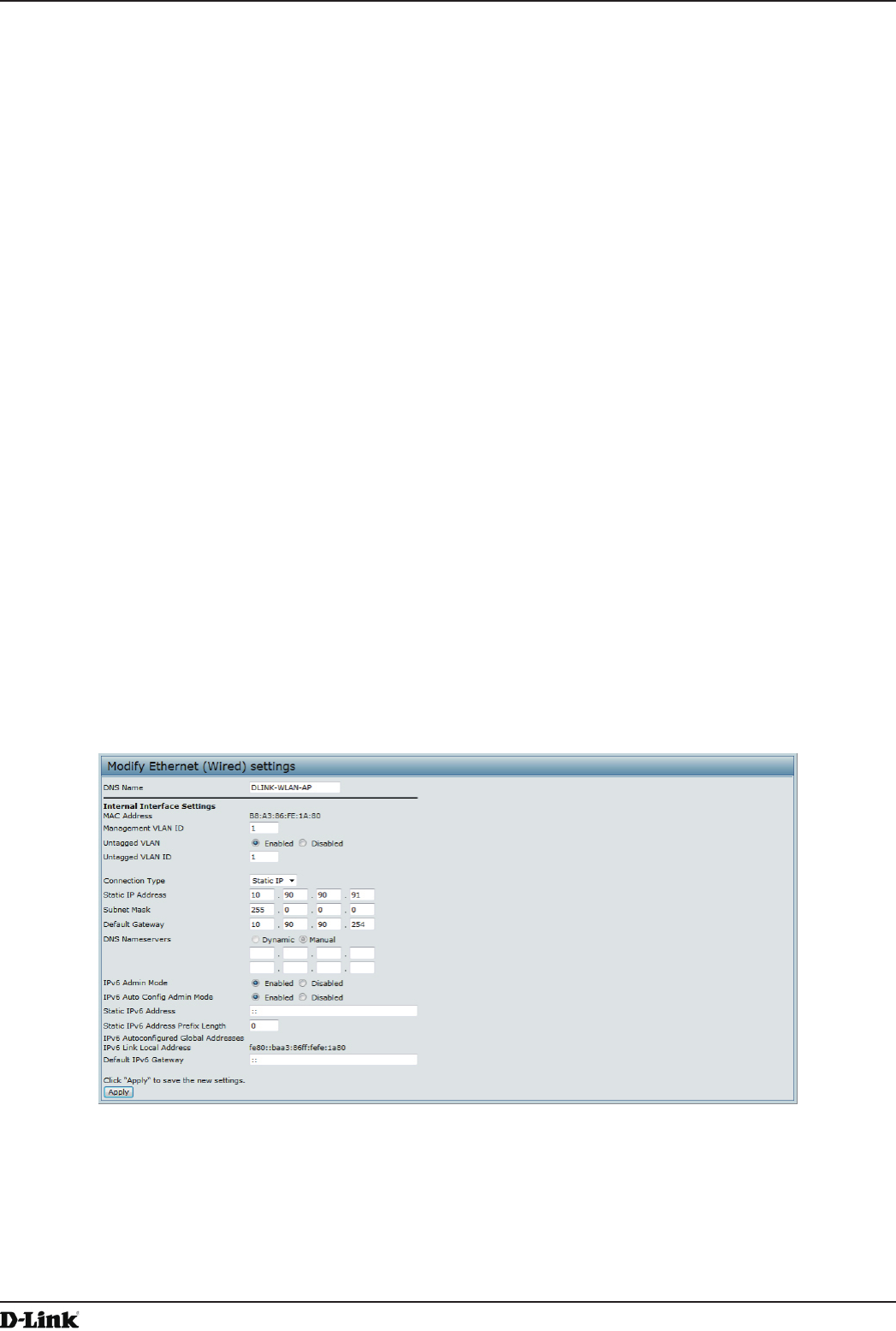
Unied Access Point Administrator’s Guide
Unied Access Point Administrator’s Guide
Page 35
May 2016
Section 4 - Managing the Access Point
Section 4 - Managing the Access Point
This section describes how to manage the UAP and contains the following subsections:
•) “Ethernet Settings” on page 35
•) “Wireless Settings” on page 37
•) “Modifying Radio Settings” on page 40
•) “Conguring Radio and VAP Scheduler” on page 44
•) “Scheduler Association Settings” on page 46
•) “Virtual Access Point Settings” on page 47
•) “Conguring the Wireless Distribution System (WDS)” on page 56
•) “Controlling Access by MAC Authentication” on page 58
•) “Conguring Load Balancing” on page 60
•) “” on page 60
•) “Conguring 802.1X Authentication” on page 62
•) “Creating a Management Access Control List (ACL)” on page 63
The conguration pages for the features in this section are located under the Manage heading on the Administration
Web UI.
Ethernet Settings
The default wired interface settings, which include DHCP and VLAN information, might not work for all networks.
By default, the DHCP client on the UAP automatically broadcasts requests for network information. If you want to
use a static IP address, you must disable the DHCP client and manually congure the IP address and other network
information.
The management VLAN is VLAN 1 by default. This VLAN is also the default untagged VLAN. If you already have
a management VLAN congured on your network with a different VLAN ID, you must change the VLAN ID of the
management VLAN on the AP.
To congure the LAN settings, click the Ethernet Settings tab.
Figure 16 - Modify Ethernet (Wired) settings
The following table describes the elds to view or congure on the Ethernet Settings page.

Unied Access Point Administrator’s Guide
Unied Access Point Administrator’s Guide
Page 36
May 2016
Section 4 - Managing the Access Point
Field Description
Hostname Enter a hostname for the AP. The hostname appears in the CLI prompt.
•) The hostname has the following requirements:
•) The length must be between 1 – 63 characters.
•) Upper and lower case characters, numbers, and hyphens are accepted.
•) The rst character must be a letter (a – z or A – Z), and the last character cannot be a
hyphen.
MAC Address Shows the MAC address for the LAN interface for the Ethernet port on this AP. This is a
read-only eld that you cannot change.
Management VLAN
ID
The management VLAN is the VLAN associated with the IP address you use to access the
AP. The default management VLAN ID is 1.
Provide a number between 1 and 4094 for the management VLAN ID.
Untagged VLAN If you disable the untagged VLAN, all trafc is tagged with a VLAN ID.
By default all trafc on the UAP uses VLAN 1, which is the default untagged VLAN. This
means that all trafc is untagged until you disable the untagged VLAN, change the untagged
trafc VLAN ID, or change the VLAN ID for a VAP or client using RADIUS.
Untagged VLAN ID Provide a number between 1 and 4094 for the untagged VLAN ID. Trafc on the VLAN that
you specify in this eld will not be tagged with a VLAN ID.
Connection Type If you select DHCP, the UAP acquires its IP address, subnet mask, DNS, and gateway
information from a DHCP server.
If you select Static IP, you must enter information in the Static IP Address, Subnet Mask,
and Default Gateway elds.
Static IP Address Enter the static IP address in the text boxes. This eld is disabled if you use DHCP as the
connection type.
Subnet Mask Enter the Subnet Mask in the text boxes.
Default Gateway Enter the Default Gateway in the text boxes.
DNS Nameservers Select the mode for the DNS.
In Dynamic mode, the IP addresses for the DNS servers are assigned automatically via
DHCP. This option is only available if you specied DHCP for the Connection Type.
In Manual mode, you must assign static IP addresses to resolve domain names.
IPv6 Admin Mode Enable or disable IPv6 management access to the AP
IPv6 Auto Cong
Admin Mode
Enable or disable IPv6 auto address conguration on the AP.
When IPv6 Auto Cong Mode is enabled, automatic IPv6 address conguration and gateway
conguration is allowed by processing the Router Advertisements received on the LAN port.
The AP can have multiple auto congured IPv6 addresses.
Static IPv6 Address Enter a static IPv6 address. The AP can have a static IPv6 address even if addresses have
already been congured automatically.
Static IPv6 Address
Prex Length
Enter the static IPv6 prex length, which is an integer in the range of 0 – 128.
IPv6 Autocongured
Global Addresses
If the AP has been assigned one or more IPv6 addresses automatically, the addresses are
listed.
IPv6 Link Local
Address
Shows the IPv6 Link Local address, which is the IPv6 address used by the local physical
link. The link local address is not congurable and is assigned by using the IPv6 Neighbor
Discovery process.
Default IPv6
Gateway
Enter the default IPv6 gateway.
Table 17 - Ethernet Settings
Note: After you congure the wired settings, you must click Apply to apply the changes and
to save the settings. Changing some settings might cause the AP to stop and restart system
processes. If this happens, wireless clients will temporarily lose connectivity. We recommend that
you change AP settings when WLAN trafc is low.
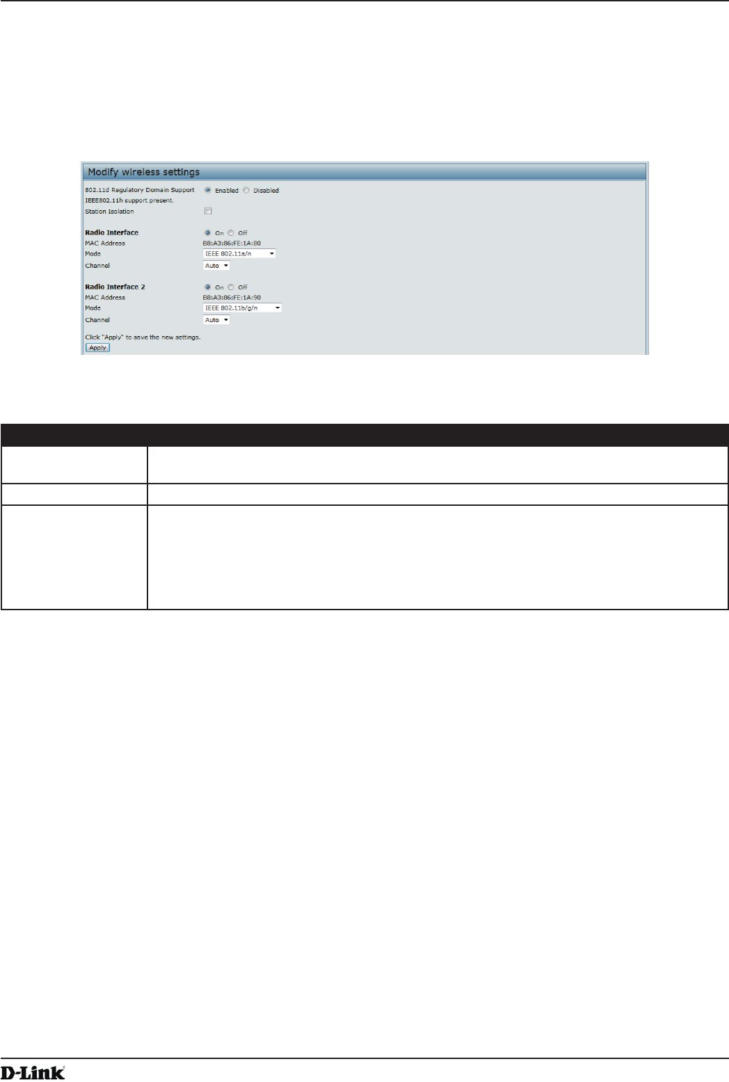
Unied Access Point Administrator’s Guide
Unied Access Point Administrator’s Guide
Page 37
May 2016
Section 4 - Managing the Access Point
Wireless Settings
Wireless settings describe aspects of the local area network (LAN) related specically to the radio device in the
access point (802.11 Mode and Channel) and to the network interface to the access point (MAC address for access
point and Wireless Network name, also known as SSID).
To congure the wireless interface, click the Manage > Wireless Settings tab.
Figure 17 - Modify Wireless Settings
The following table describes the elds and conguration options available on the Wireless Settings page.
Field Description
TSPEC Violation
Interval
Specify the time interval (in seconds) for the AP to report (through the system log and SNMP
traps) associated clients that do not adhere to mandatory admission control procedures.
Radio Interface Specify whether you want the radio interface on or off.
MAC Address Indicates the Media Access Control (MAC) addresses for the interface. Dual-radio APs have
a unique MAC address for each radio.
A MAC address is a permanent, unique hardware address for any device that represents
an interface to the network. The MAC address is assigned by the manufacturer. You cannot
change the MAC address. It is provided here for informational purposes as a unique
identier for an interface.

Unied Access Point Administrator’s Guide
Unied Access Point Administrator’s Guide
Page 38
May 2016
Section 4 - Managing the Access Point
Field Description
Mode The Mode denes the Physical Layer (PHY) standard the radio uses.
Note: The modes available depend on the country code setting and the radio selected.
Select one of the following modes for radio 1:
•) IEEE 802.11a is a PHY standard that species operating in the 5 GHz U-NII band
using orthogonal frequency division multiplexing (OFDM). It supports data rates
ranging from 6 to 54 Mbps.
•) IEEE 802.11a/n operates in the 5 GHz ISM band and includes support for both
802.11a and 802.11n devices. IEEE 802.11n is an extension of the 802.11 standard
that includes multiple-input multiple-output (MIMO) technology. IEEE 802.11n
supports data ranges of up to 248 Mbps and nearly twice the indoor range of 802.11
b, 802.11g, and 802.11a.
•) 5 GHz IEEE 802.11n is the recommended mode for networks with 802.11n devices
that operate in the 5 GHz frequency that do not need to support 802.11a devices.
IEEE 802.11n can achieve a higher throughput when it does not need to be
compatible with legacy devices (802.11a).
Select one of the following modes for radio 2:
•) IEEE 802.11b/g operates in the 2.4 GHz ISM band. IEEE 802.11b is an enhancement
of the initial 802.11 PHY to include 5.5 Mbps and 11 Mbps data rates. It uses direct
sequence spread spectrum (DSSS) or frequency hopping spread spectrum (FHSS)
as well as complementary code keying (CCK) to provide the higher data rates. It
supports data rates ranging from 1 to 11 Mbps. IEEE 802.11g is a higher speed
extension (up to 54 Mbps) to the 802.11b PHY. It uses orthogonal frequency division
multiplexing (OFDM). It supports data rates ranging from 1 to 54 Mbps.
•) IEEE 802.11b/g/n operates in the 2.4 GHz ISM band and includes support for 802.11b,
802.11g, and 802.11n devices.
•) 2.4 GHz IEEE 802.11n is the recommended mode for networks with 802.11n devices
that operate in the 2.4 GHz frequency that do not need to support 802.11b/g
devices. IEEE 802.11n can achieve a higher throughput when it does not need to be
compatible with legacy devices (802.11b/g).
Channel Select the Channel.
The range of available channels is determined by the mode of the radio interface and the
country code setting. If you select Auto for the channel setting, the AP scans available
channels and selects a channel where no trafc is detected.
The Channel denes the portion of the radio spectrum the radio uses for transmitting and
receiving. Each mode offers a number of channels, depending on how the spectrum is
licensed by national and transnational authorities such as the Federal Communications
Commission (FCC) or the International Telecommunication Union (ITU-R).
When automatic channel assignment is enabled on the Channel Management page for
Clustering, the channel policy for the radio is automatically set to static mode, and the Auto
option is not available for the Channel eld. This allows the automatic channel feature to set
the channels for the radios in the cluster.
Station Isolation To enable Station Isolation, select the check box directly beside it.
When Station Isolation is disabled, wireless clients can communicate with one another
normally by sending trafc through the AP.
When Station Isolation is enabled, the AP blocks communication between wireless clients
on the same radio and VAP. The AP still allows data trafc between its wireless clients and
wired devices on the network, across a WDS link, and with other wireless clients associated
with a different VAP, but not among wireless clients associated with the same VAP.
Unied Access Point Administrator’s Guide
Unied Access Point Administrator’s Guide
Page 39
May 2016
Section 4 - Managing the Access Point
Field Description
AeroScout™ Engine
Protocol Support
AeroScout Engine support provides location-based services for wireless networks. Specify
whether to enable support for the AeroScout protocol.
Options are Enabled or Disabled. The default is Disabled. When enabled, Aeroscout
devices are recognized and data is sent to an Aeroscout Engine (AE) for analysis. The AE
determines the geographical location of 802.11 capable devices, such as STAs, APs, and
AeroScout’s line of 802.11 enabled RFID devices, or tags. The AE communicates with APs
that support the AE protocol in order to collect information about the RF devices detected
by the APs. Using the AE protocol, D-Link supports direct communication between AE and
the APs. When operating in managed mode, the AE is congured with the IP address of
the managed access points from which it collects information. The Wireless Switch cannot
communicate with the AE.
For more information about the AeroScout protocol, see “Enabling AeroScout™ Engine
Support” on page 39.
Note: Only AeroScout tag hardware of types T2 and T3 are explicitly supported. Other tag
models are also supported only if their implementation of the AeroScout protocol conforms
to the AeroScout Engine - Access Point Interface Specication, version 2.1.
Note: AeroScout tags operate only in 802.11 b/g mode. Therefore, network administrators
who use the AeroScout tags must congure at least one radio on APs that are expected to
detect tags in either 802.11b/g or 802.11b/g/n mode. The radios congured in 2.4 GHz IEEE
802.11 mode or any of the 5GHz modes cannot detect AeroScout tags.
Note: The AE protocol allows access points to mark detected APs as rogue devices. The
D-Link APs do not support this feature and never report detected APs as rogues.
Table 18 - Wireless Settings
Note: After you congure the wireless settings, you must click Apply to apply the changes and
to save the settings. Changing some settings might cause the AP to stop and restart system
processes. If this happens, wireless clients will temporarily lose connectivity. We recommend that
you change AP settings when WLAN trafc is low.
Using the 802.11h Wireless Mode
For 802.11a radios, if the regulatory domain requires radar detection on the channel, the Dynamic Frequency
Selection (DFS) and Transmit Power Control (TPC) features of 802.11h are automatically activated.
There are a number of key points about the IEEE 802.11h standard:
•) 802.11h only works for the 802.11a band. It is not required for 802.11b or 802.11g.
•) If you are operating in an 802.11h enabled domain, the AP attempts to use the channel you assign. If the channel
has been blocked by a previous radar detection, or if the AP detects a radar on the channel, then the AP
automatically selects a different channel.
•) When 802.11h is enabled, the AP will not be operational in the 5GHz band for at least 60 seconds due to radar
scanning.
•) Setting up WDS links may be difcult when 802.11h is operational. This is because the operating channels of the
two APs on the WDS link may keep changing depending on channel usage and radar interference. WDS will
only work if both the APs operate on the same channel. For more information on WDS, see “Conguring Load
Balancing” on page 60.
Enabling AeroScout™ Engine Support
The AeroScout Engine (AE) is a software platform produced by AeroScout Inc. for location-based services. The AE
can determine the physical location of 802.11 capable AeroScout devices. The AE communicates with APs that have
the AE protocol enabled in order to collect information about the RF devices detected by the APs.
The DWS-4000 Series switch supports only direct communication between the AE and the APs. When operating
in managed mode, the AE is congured with the IP address of the managed access points from which it collects
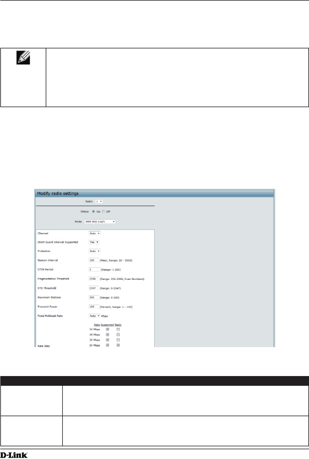
Unied Access Point Administrator’s Guide
Unied Access Point Administrator’s Guide
Page 40
May 2016
Section 4 - Managing the Access Point
information. The DWS-4000 Series switch does not communicate with the AE.
AeroScout tags operate only in 802.11b/g mode. Therefore, network administrators who use the AeroScout tags must
congure at least one radio on APs that are expected to detect tags in either 802.11b/g or 802.11b/g/n mode. The
radios congured in 2.4 GHz IEEE 802.11n mode cannot detect AeroScout tags.
Note: The following notes apply to AeroScout product and protocol support:
•) D-Link does not sell AeroScout products. Contact AeroScout for AeroScout hardware,
software or deployment information.
•) The AE protocol does not support any authentication or encryption between the AE server
and the access point.
•) The AE protocol requires radios to operate in promiscuous mode. This means that the AP
receives and processes all packets detected by the radios, as opposed to processing only
packets destined to the APs BSSID. This can affect AP throughput.
Modifying Radio Settings
Radio settings directly control the behavior of the radio devices in the AP and its interaction with the physical medium;
that is, how and what type of electromagnetic waves the AP emits.
To specify radio settings, click the Radio tab in the Manage section.
Different settings display depending on the mode you select. All settings are described in the table below.
Figure 18 - Modify Radio Settings
The following table describes the elds and conguration options for the Radio Settings page.
Field Description
Radio Select Radio 1or Radio 2 to specify which radio to congure. The rest of the settings on this
page apply to the radio you select in this eld. Be sure to congure settings for both radios.
Radio 1 operates in the 5 GHz band (802.11a/n), and Radio 2 operates in the 2.4 GHz band
(802.11b/g/n).
Status (On/Off) Specify whether you want the radio on or off by clicking On or Off.
If you turn off a radio, the AP sends disassociation frames to all the wireless clients it is
currently supporting so that the radio can be gracefully shutdown and the clients can start
the association process with other available APs.

Unied Access Point Administrator’s Guide
Unied Access Point Administrator’s Guide
Page 41
May 2016
Section 4 - Managing the Access Point
Field Description
Mode The Mode denes the Physical Layer (PHY) standard the radio uses.
Note: The modes available depend on the country code setting and the radio selected.
Select one of the following modes for radio 1:
•) IEEE 802.11a is a PHY standard that species operating in the 5 GHz U-NII band
using orthogonal frequency division multiplexing (OFDM). It supports data rates
ranging from 6 to 54 Mbps.
•) IEEE 802.11a/n operates in the 5 GHz ISM band and includes support for both
802.11a and 802.11n devices. IEEE 802.11n is an extension of the 802.11 standard
that includes multiple-input multiple-output (MIMO) technology. IEEE 802.11n
supports data ranges of up to 248 Mbps and nearly twice the indoor range of 802.11
b, 802.11g, and 802.11a.
•) 5 GHz IEEE 802.11n is the recommended mode for networks with 802.11n devices
that operate in the 5 GHz frequency that do not need to support 802.11a devices.
IEEE 802.11n can achieve a higher throughput when it does not need to be
compatible with legacy devices (802.11a).
Select one of the following modes for radio 2:
•) IEEE 802.11b/g operates in the 2.4 GHz ISM band. IEEE 802.11b is an enhancement
of the initial 802.11 PHY to include 5.5 Mbps and 11 Mbps data rates. It uses direct
sequence spread spectrum (DSSS) or frequency hopping spread spectrum (FHSS)
as well as complementary code keying (CCK) to provide the higher data rates. It
supports data rates ranging from 1 to 11 Mbps. IEEE 802.11g is a higher speed
extension (up to 54 Mbps) to the 802.11b PHY. It uses orthogonal frequency division
multiplexing (OFDM). It supports data rates ranging from 1 to 54 Mbps.
•) IEEE 802.11b/g/n operates in the 2.4 GHz ISM band and includes support for 802.11b,
802.11g, and 802.11n devices.
•) 2.4 GHz IEEE 802.11n is the recommended mode for networks with 802.11n devices
that operate in the 2.4 GHz frequency that do not need to support 802.11b/g
devices. IEEE 802.11n can achieve a higher throughput when it does not need to be
compatible with legacy devices (802.11b/g).
Channel Select the Channel.
The range of available channels is determined by the mode of the radio interface and the
country code setting. If you select Auto for the channel setting, the AP scans available
channels and selects a channel where no trafc is detected.
The channel denes the portion of the radio spectrum the radio uses for transmitting and
receiving. Each mode offers a number of channels, depending on how the spectrum is
licensed by national and transnational authorities such as the Federal Communications
Commission (FCC) or the International Telecommunication Union (ITU-R).
When automatic channel assignment is enabled on the Channel Management page for
Clustering, the channel policy for the radio is automatically set to static mode, and the Auto
option is not available for the Channel eld. This allows the automatic channel feature to set
the channels for the radios in the cluster.
Channel Bandwidth
(802.11n modes
only)
The 802.11n specication allows a 40 MHz wide channel in addition to the legacy 20 MHz
channel available with other modes. The 40 MHz channel enables higher data rates but
leaves fewer channels available for use by other 2.4 GHz and 5 GHz devices.
Set the eld to 20 MHz to restrict the use of the channel bandwidth to a 20 MHz channel.
Primary Channel
(802.11n modes
only)
This setting can be changed only when the channel bandwidth is set to 40 MHz. A 40 MHz
channel can be considered to consist of two 20 MHz channels that are contiguous in the
frequency domain. These two 20 MHz channels are often referred to as the Primary and
Secondary channels. The Primary Channel is used for 802.11n clients that support only a
20 MHz channel bandwidth and for legacy clients.
Select one of the following options:
•) Lower — Set the Primary Channel as the lower 20 MHz channel in the 40 MHz band.
•) Upper — Set the Primary Channel as the upper 20 MHz channel in the 40 MHz band.

Unied Access Point Administrator’s Guide
Unied Access Point Administrator’s Guide
Page 42
May 2016
Section 4 - Managing the Access Point
Field Description
Short Guard Interval
Supported
This eld is available only if the selected radio mode includes 802.11n.
The guard interval is the dead time, in nanoseconds, between OFDM symbols. The guard
interval prevents Inter-Symbol and Inter-Carrier Interference (ISI, ICI). The 802.11n mode
allows for a reduction in this guard interval from the a and g denition of 800 nanoseconds
to 400 nanoseconds. Reducing the guard interval can yield a 10% improvement in data
throughput.
Select one of the following options:
•) Yes — The AP transmits data using a 400ns guard Interval when communicating with
clients that also support the short guard interval.
•) No — The AP transmits data using an 800ns guard interval.
STBC Mode This eld is available only if the selected radio mode includes 802.11n.
Space Time Block Coding (STBC) is an 802.11n technique intended to improve the reliability
of data transmissions. The data stream is transmitted on multiple antennas so the receiving
system has a better chance of detecting at least one of the data streams.
Select one of the following options:
•) On — The AP transmits the same data stream on multiple antennas at the same time.
•) Off — The AP does not transmits the same data on multiple antennas.
Protection The protection feature contains rules to guarantee that 802.11n transmissions do not cause
interference with legacy stations or APs. By default, these protection mechanisms are
enabled (Auto). With protection enabled, protection mechanisms will be invoked if legacy
devices are within range of the AP. This causes more overhead on every transmission,
which will impact performance. However, there is no impact on performance if there are no
legacy devices within range of the AP.
You can disable (Off) these protection mechanisms; however, when 802.11n protection is
off, legacy clients or APs within range can be affected by 802.11n transmissions. The 802.11
protection feature is also available when the mode is 802.11b/g. When protection is enabled
in this mode, it protects 802.11b clients and APs from 802.11g transmissions.
Note: This setting does not affect the ability of the client to associate with the AP.
Beacon Interval Beacon frames are transmitted by an AP at regular intervals to announce the existence
of the wireless network. The default behavior is to send a beacon frame once every 100
milliseconds (or 10 per second).
Enter a value from 20 to 2000 milliseconds.
DTIM Period Specify a DTIM period from 1 to 255 beacons.
The Delivery Trafc Information Map (DTIM) message is an element included in some
Beacon frames. It indicates which client stations, currently sleeping in low-power mode,
have data buffered on the AP awaiting pick-up.
The DTIM period you specify indicates how often the clients served by this AP should check
for buffered data still on the AP awaiting pickup.
The measurement is in beacons. For example, if you set this eld to 1, clients will check
for buffered data on the AP at every beacon. If you set this eld to 10, clients will check on
every 10th beacon.
Fragmentation
Threshold
Specify a number between 256 and 2,346 to set the frame size threshold in bytes.
The fragmentation threshold is a way of limiting the size of packets (frames) transmitted
over the network. If a packet exceeds the fragmentation threshold you set, the fragmentation
function is activated and the packet is sent as multiple 802.11 frames.
If the packet being transmitted is equal to or less than the threshold, fragmentation is not
used.
Setting the threshold to the largest value (2,346 bytes) effectively disables fragmentation.
Fragmentation plays no role when Aggregation is enabled.
Fragmentation involves more overhead both because of the extra work of dividing up and
reassembling of frames it requires, and because it increases message trafc on the network.
However, fragmentation can help improve network performance and reliability if properly
congured.
Sending smaller frames (by using lower fragmentation threshold) might help with some
interference problems; for example, with microwave ovens.
By default, fragmentation is off. We recommend not using fragmentation unless you suspect
radio interference. The additional headers applied to each fragment increase the overhead
on the network and can greatly reduce throughput.

Unied Access Point Administrator’s Guide
Unied Access Point Administrator’s Guide
Page 43
May 2016
Section 4 - Managing the Access Point
Field Description
RTS Threshold Specify a Request to Send (RTS) Threshold value between 0 and 2347.
The RTS threshold indicates the number of octets in an MPDU, below which an RTS/CTS
handshake is not performed.
Changing the RTS threshold can help control trafc ow through the AP, especially one
with a lot of clients. If you specify a low threshold value, RTS packets will be sent more
frequently. This will consume more bandwidth and reduce the throughput of the packet.
On the other hand, sending more RTS packets can help the network recover from
interference or collisions which might occur on a busy network, or on a network experiencing
electromagnetic interference.
Maximum Stations Specify the maximum number of stations allowed to access this AP at any one time.
You can enter a value between 0 and 200.
Transmit Power Enter a percentage value for the transmit power level for this AP.
The default value, which is 100%, can be more cost-efcient than a lower percentage since
it gives the AP a maximum broadcast range and reduces the number of APs needed.
To increase capacity of the network, place APs closer together and reduce the value of the
transmit power. This helps reduce overlap and interference among APs. A lower transmit
power setting can also keep your network more secure because weaker wireless signals are
less likely to propagate outside of the physical location of your network.
Fixed Multicast Rate Select the multicast trafc transmission rate you want the AP to support.
Legacy Rate Sets Check the transmission rate sets you want the AP to support and the basic rate sets you
want the AP to advertise:
•) Rates are expressed in megabits per second.
•) Supported Rate Sets indicate rates that the AP supports. You can check multiple rates
(click a check box to select or de-select a rate). The AP will automatically choose the
most efcient rate based on factors like error rates and distance of client stations from
the AP.
•) Basic Rate Sets indicate rates that the AP will advertise to the network for the
purposes of setting up communication with other APs and client stations on the
network. It is generally more efcient to have an AP broadcast a subset of its
supported rate sets.
MCS (Data Rate)
Settings (802.11n
modes only)
This eld shows the Modulation and Coding Scheme (MCS) index values supported by the
radio. Each index can be enabled and disabled independently.
Broadcast/Multicast
Rate Limiting
Enabling multicast and broadcast rate limiting can improve overall network performance by
limiting the number of packets transmitted across the network.
By default the Multicast/Broadcast Rate Limiting option is disabled. Until you enable
Multicast/Broadcast Rate Limiting, the following elds will be disabled:
•) Rate Limit - Enter the rate limit you want to set for multicast and broadcast trafc. The
limit should be greater than 1, but less than 50 packets per second. Any trafc that
falls below this rate limit will always conform and be transmitted to the appropriate
destination. The default and maximum rate limit setting is 50 packets per second.
•) Rate Limit Burst - Setting a rate limit burst determines how much trafc bursts can
be before all trafc exceeds the rate limit. This burst limit allows intermittent bursts of
trafc on a network above the set rate limit. The default and maximum rate limit burst
setting is 75 packets per second.
TSPEC Mode Regulates the overall TSPEC mode on the AP. The options are:
•) On — The AP handles TSPEC requests according to the TSPEC settings you
congure on the Radio page. Use this setting if the AP handles trafc from QoS-
capable devices, such as a Wi-Fi CERTIFIED phone.
•) Off — The AP ignores TSPEC requests from client stations. Use this setting if you do
not want to use TSPEC to give QoS-capable devices priority for time-sensitive trafc.
TSPEC Voice ACM
Mode
Regulates mandatory admission control (ACM) for the voice access category. The options
are:
•) On — A station is required to send a TSPEC request for bandwidth to the AP before
sending or receiving a voice trafc stream. The AP responds with the result of the
request, which includes the allotted medium time if the TSPEC was admitted.
•) Off — A station can send and receive voice priority trafc without requiring an admitted
TSPEC; the AP ignores voice TSPEC requests from client stations.

Unied Access Point Administrator’s Guide
Unied Access Point Administrator’s Guide
Page 44
May 2016
Section 4 - Managing the Access Point
Field Description
TSPEC Voice ACM
Limit
Specify an upper limit on the amount of trafc the AP attempts to transmit on the wireless
medium using a voice AC to gain access.
TSPEC Video ACM
Mode
Regulates mandatory admission control for the video access category. The options are:
•) On — A station is required to send a TSPEC request for bandwidth to the AP before
sending or receiving a video trafc stream. The AP responds with the result of the
request, which includes the allotted medium time if the TSPEC was admitted.
•) Off — A station can send and receive video priority trafc without requiring an admitted
TSPEC; the AP ignores video TSPEC requests from client stations.
TSPEC Video ACM
Limit
Specify an upper limit on the amount of trafc the AP attempts to transmit on the wireless
medium using a video AC to gain access.
TSPEC AP Inactivity
Timeout
Specify the amount of time for an AP to detect an downlink TS as idle before deleting it.
TSPEC Station
Inactivity Timeout
Specify the amount of time for an AP to detect an uplink TS as idle before deleting it.
TSPEC Legacy
WMM Queue Map
Mode
Select Enable to allow intermixing of legacy trafc on queues operating as ACM.
Table 19 - Radio Settings
Use the Radio page to congure both Radio One and Radio Two. The settings on the page apply only to the radio
that you choose from the Radio drop-down list. After you congure settings for one of the radios, click Apply and then
select and congure the other radio. Be sure to click Apply to apply the second set of conguration settings for the
other radio.
Conguring Radio and VAP Scheduler
The Radio and VAP scheduler is a standalone DWL-x600AP feature. To congure the Radio and VAP scheduler,
select the Scheduler tab in the Manage section. The Radio and VAP Scheduler allows you to congure a rule with a
specic time interval for VAPs or radios to be operational, thereby automating the enabling or disabling of the VAPs
and Radios.
One of the ways you can use this feature is to schedule radios to operate only during the ofce working hours in order
to achieve security and reduce power consumption. You can also use the Scheduler to allow access to VAPs for
wireless clients only during specic times of day.
Each rule species the start time, end time and day (or days) of the week the radio or VAP can be operational. The
rules are periodic in nature and are repeated every week.
A valid rule must contain all of the following parameters:
•) Days of the Week.
•) Start Time (hour and minutes).
•) End Time (hour and minutes).
Only valid rules are added to the prole. Up to 16 rules are grouped together to form a scheduling prole. Any two
periodic rules time entries belonging to the same prole must not overlap. The time granularity for the schedules is
one minute. The DWL-x600AP supports up to 16 proles.
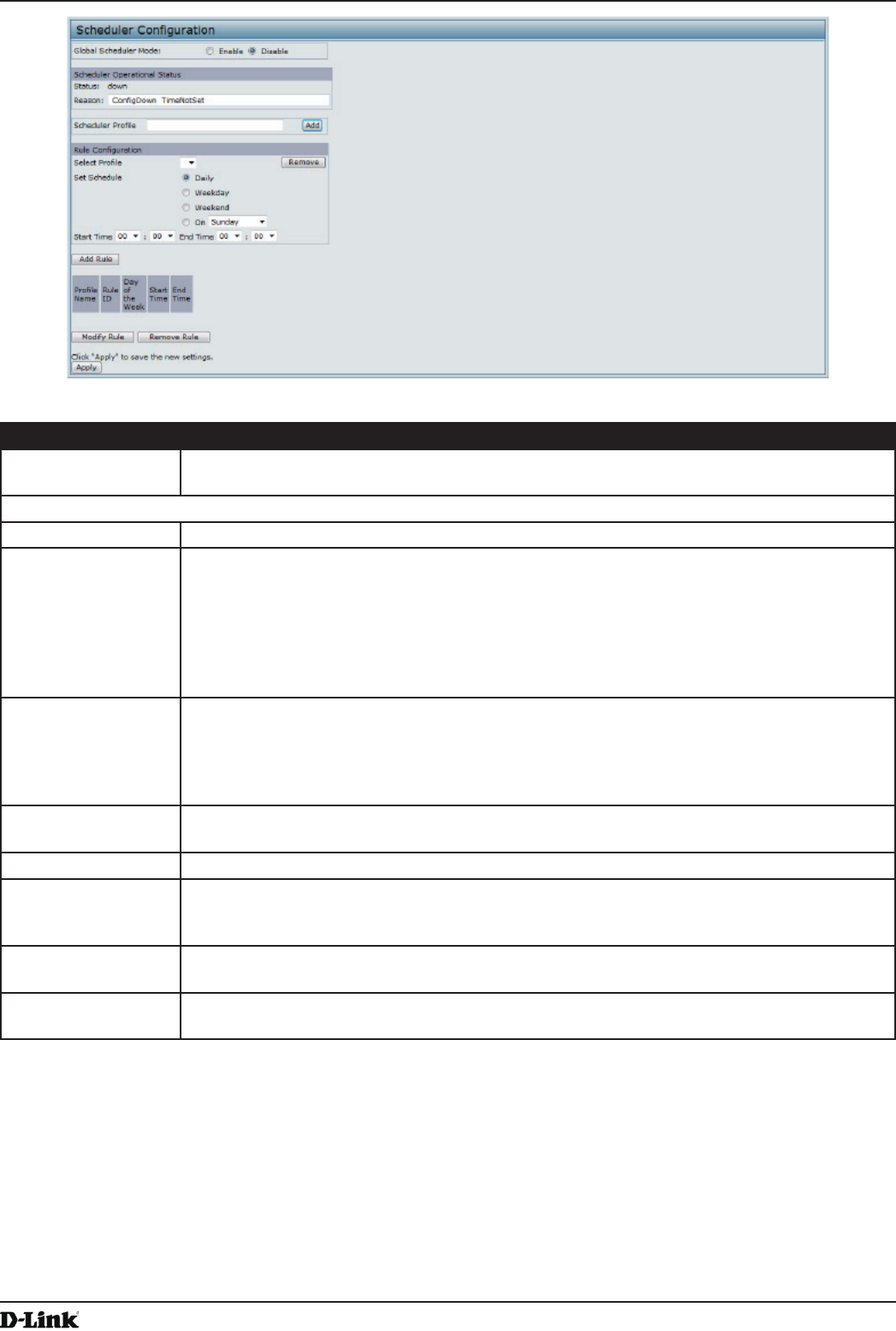
Unied Access Point Administrator’s Guide
Unied Access Point Administrator’s Guide
Page 45
May 2016
Section 4 - Managing the Access Point
Figure 19 - Scheduler Conguration
Field Description
Global Scheduler
Mode
A global switch to enable or disable the scheduler feature. The default is Disable.
Scheduler Operational Status
Status The operational status of the Scheduler. The range is Up or Down. The default is Down.
Reason Provides additional information about the status. The reason can be one or more of the
following:
•) IsActive – Operational status is up.
•) CongDown – Operational status is down because global conguration is disabled.
•) TimeNotSet – Operational status is down because the AP time has not been set,
either manually or by specifying an NTP server to use.
•) ManagedMode– Operational status is down because the AP is in managed mode.
Scheduler Prole The Scheduler prole denes the list of proles names that can be associated to the VAP or
Radio conguration. Rules are associated with a named scheduler prole. You can dene up
to 16 scheduler prole names. By default, no proles are created.
The prole name can be up to 32 alphanumeric characters. Click Add to add the prole
name.
Rule Conguration Each scheduler prole may have up to 16 periodic rules. The list of parameters for each
periodic rule are described below.
Select Prole Select the prole name from the menu.
Set Schedule The day of the week. Range is: Daily, Weekday (Monday to Friday), Weekend (Saturday
and Sunday), Monday, Tuesday, Wednesday, Thursday, Friday, Saturday, Sunday. The
default is Daily.
Start Time The time when the radio or VAP will be operationally enabled. The time is in HH:MM 24-hour
format. The range is <00-24>:<00-59>. The default is 00:00.
End Time The time when the radio or VAP will be operationally disabled. The time is in HH:MM 24-
hour format. The range is <00-24>:<00-59>. The default is 00:00.
Table 20 - Scheduler Conguration
To change an existing rule, select the rule, update the values in the Rule Conguration area, and click Modify Rule.
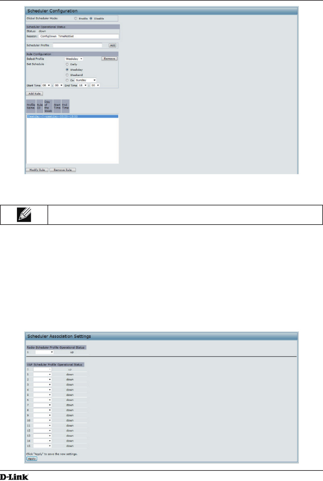
Unied Access Point Administrator’s Guide
Unied Access Point Administrator’s Guide
Page 46
May 2016
Section 4 - Managing the Access Point
Figure 20 - Scheduler Conguration (Modify Rule)
Click Apply to save the new conguration settings.
Note: After making any modications, you must click Apply to apply the changes and to save the
settings.
Scheduler Association Settings
For a Scheduler prole to take effect, you must associate it with at least one radio or VAP interface. To associate the
Scheduler proles, select the Scheduler Association tab in the Manage section. By default, there are no Scheduler
proles created, so no prole is associated to any radio or VAP. The Scheduler prole needs to be explicitly associated
to a radio or VAP conguration. Only one Scheduler prole can be associated to any radio or VAP conguration;
however, a single prole can be associated to multiple radios or VAPs. If the Scheduler prole associated with a VAP
or radio is deleted, then the associated prole to the VAP or radio is removed implicitly. If the radio is operationally
disabled, then all the VAPs associated to that radio are also operationally disabled irrespective of the VAP
conguration.
Figure 21 - Scheduler Association Settings
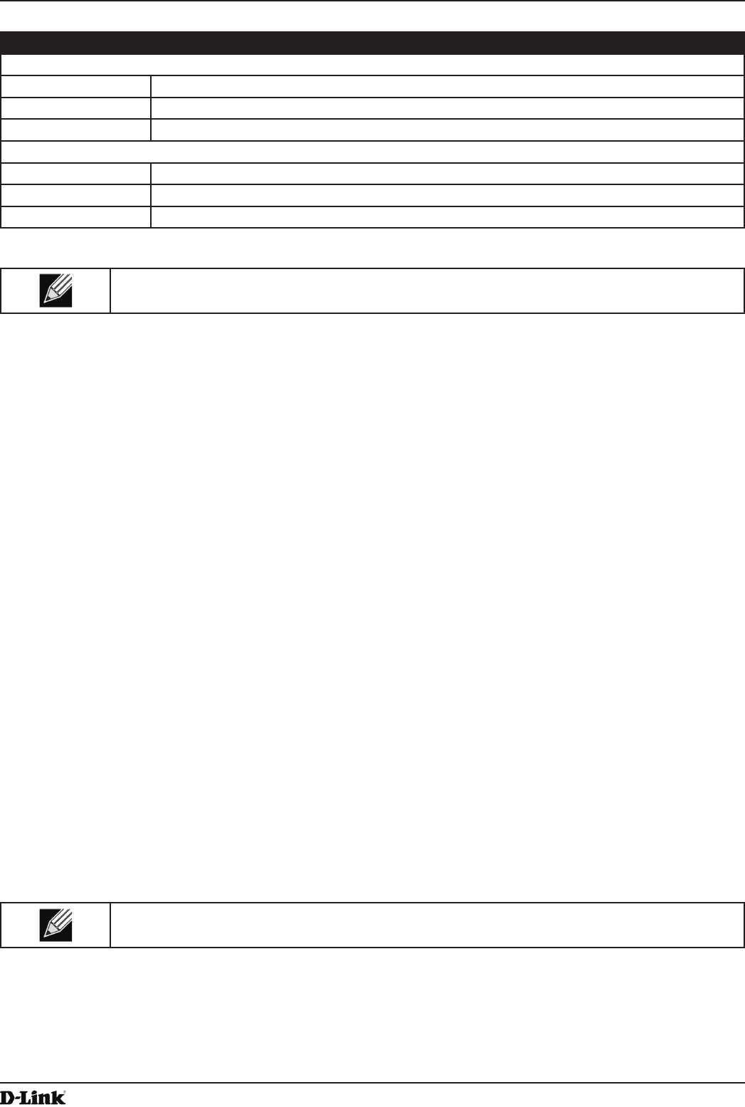
Unied Access Point Administrator’s Guide
Unied Access Point Administrator’s Guide
Page 47
May 2016
Section 4 - Managing the Access Point
Field Description
Radio Scheduler Prole Operational Status
1 or 2 From the menu, select the Scheduler prole to associate with Radio 1 or Radio 2.
Scheduler Prole From the menu, select the Scheduler prole to associate with the Radio.
Status The operational status of the Scheduler. The range is Up or Down.
VAP Scheduler Prole Operational Status
Radio From the menu, select Radio 1 or Radio 2 to associate the VAP Scheduler Prole.
0-15 From the menu, select the Scheduler prole to associate with the respective VAP.
Status The operational status of the Scheduler. The range is Up or Down.
Table 21 - Scheduler Association Settings
Note: After you associate a Scheduler prole with a Radio interface or a VAP interface, you must
click Apply to apply the changes and to save the settings.
Virtual Access Point Settings
To change VAP 0 or to enable and congure additional VAPs, select the VAP tab in the Manage section.
VAPs segment the wireless LAN into multiple broadcast domains that are the wireless equivalent of Ethernet VLANs.
VAPs simulate multiple APs in one physical AP. Each radio supports up to 16 VAPs.
For each VAP, you can customize the security mode to control wireless client access. Each VAP can also have
a unique SSID. Multiple SSIDs make a single AP look like two or more APs to other systems on the network.
By conguring VAPs, you can maintain better control over broadcast and multicast trafc, which affects network
performance.
You can congure each VAP to use a different VLAN, or you can congure multiple VAPs to use the same VLAN,
whether the VLAN is on the same radio or on a different radio. VAP0, which is always enabled on both radios, is
assigned to the default VLAN 1.
The AP adds VLAN ID tags to wireless client trafc based on the VLAN ID you congure on the VAP page or by using
the RADIUS server assignment. If you use an external RADIUS server, you can congure multiple VLANs on each
VAP. The external RADIUS server assigns wireless clients to the VLAN when the clients associate and authenticate.
You can congure up to four global IPv4 or IPv6 RADIUS servers. One of the servers always acts as a primary while
the others act as backup servers. The network type (IPv4 or IPv6) and accounting mode are common across all
congured RADIUS servers. You can congure each VAP to use the global RADIUS server settings, which is the
default, or you can congure a per-VAP RADIUS server set. You can also congure separate RADIUS server settings
for each VAP. For example, you can congure one VAP to use an IPv6 RADIUS server while other VAPs use the
global IPv4 RADIUS server settings you congure.
If wireless clients use a security mode that does not communicate with the RADIUS server, or if the RADIUS server
does not provide the VLAN information, you can assign a VLAN ID to each VAP. The AP assigns the VLAN to all
wireless clients that connect to the AP through that VAP.
Note: Before you congure VLANs on the AP, be sure to verify that the switch and DHCP server
the AP uses can support IEEE 802.1Q VLAN encapsulation.
To set up multiple VAPs, click Manage > VAP.

Unied Access Point Administrator’s Guide
Unied Access Point Administrator’s Guide
Page 48
May 2016
Section 4 - Managing the Access Point
Figure 22 - Modify Virtual Access Point Settings
The following table describes the elds and conguration options on the VAP page.
Field Description
RADIUS IP Address
Type
Specify the IP version that the RADIUS server uses.
You can toggle between the address types to congure IPv4 and IPv6 global RADIUS
address settings, but the AP contacts only the RADIUS server or servers for the address
type you select in this eld.
RADIUS IP Address
RADIUS IPv6
Address
Enter the IPv4 or IPv6 address for the primary global RADIUS server. By default, each VAP
uses the global RADIUS settings that you dene for the AP at the top of the VAP page.
When the rst wireless client tries to authenticate with the AP, the AP sends an
authentication request to the primary server. If the primary server responds to the
authentication request, the AP continues to use this RADIUS server as the primary server,
and authentication requests are sent to the address you specify.
If the IPv4 RADIUS IP Address Type option is selected in the previous eld, enter the IP
address of the RADIUS server that all VAPs use by default, for example 192.168.10.23.
If the IPv6 RADIUS IP Address Type option is selected, enter the IPv6 address of the
primary global RADIUS server, for example 2001:0db8:1234::abcd.
RADIUS IP or IPv6
Address 1–3
Enter up to three IPv4 or IPv6 addresses to use as the backup RADIUS servers. The eld
label is RADIUS IP Address when the IPv4 RADIUS IP Address Type option is selected and
RADIUS IPv6 Address when the IPv6 RADIUS IP Address Type option is selected.
If authentication fails with the primary server, each congured backup server is tried in
sequence. The IPv4 or IPv6 address must be valid in order for the AP to attempt to contact
the server.
RADIUS Key Enter the RADIUS key in the text box.
The RADIUS Key is the shared secret key for the global RADIUS server. You can use up to
63 standard alphanumeric and special characters. The key is case sensitive, and you must
congure the same key on the AP and on your RADIUS server. The text you enter will be
displayed as “*” characters to prevent others from seeing the RADIUS key as you type.
RADIUS Key 1–3 Enter the RADIUS key associated with the congured backup RADIUS servers. The server
at RADIUS IP Address-1 uses RADIUS Key-1, RADIUS IP Address-2 uses RADIUS Key-2,
and so on.
Enable RADIUS
Accounting
Select this option to track and measure the resources a particular user has consumed
such as system time, amount of data transmitted and received, and so on.
If you enable RADIUS accounting, it is enabled for the primary RADIUS server and all
backup servers.
Enable RADIUS
FailThrough
Select this option to allow the secondary RADIUS server to authenticate wireless clients
if the authentication with the primary RADIUS server is unsuccessful, or if the primary
RADIUS server is unavailable.

Unied Access Point Administrator’s Guide
Unied Access Point Administrator’s Guide
Page 49
May 2016
Section 4 - Managing the Access Point
Field Description
Radio Select the radio to congure. VAPs are congured independently on each radio.
VAP You can congure up to 16 VAPs for each radio. VAP0 is the physical radio interface, so to
disable VAP0, you must disable the radio.
Enabled You can enable or disable a congured network.
•) To enable the specied network, select the Enabled option beside the appropriate
VA P.
•) To disable the specied network, clear the Enabled option beside the appropriate VAP.
If you disable the specied network, you will lose the VLAN ID you entered.
VLAN ID When a wireless client connects to the AP by using this VAP, the AP tags all trafc from the
wireless client with the VLAN ID you enter in this eld unless you enter the untagged VLAN
ID or use a RADIUS server to assign a wireless client to a VLAN. The range for the VLAN ID
is 1 – 4094.
If you use RADIUS-based authentication for clients, you can optionally add the following
attributes to the appropriate le in the RADIUS or AAA server to congure a VLAN for the
client:
•) “Tunnel-Type”
•) “Tunnel-Medium-Type”
•) “Tunnel-Private-Group-ID”
The RADIUS-assigned VLAN ID overrides the VLAN ID you congure on the VAP page.
You congure the untagged and management VLAN IDs on the Ethernet Settings page. For
more information, see “Ethernet Settings” on page 35.
SSID Enter a name for the wireless network. The SSID is an alphanumeric string of up to 32
characters. You can use the same SSID for multiple VAPs, or you can choose a unique
SSID for each VAP.
Note: If you are connected as a wireless client to the same AP that you are administering,
resetting the SSID will cause you to lose connectivity to the AP. You will need to reconnect to
the new SSID after you save this new setting.
Broadcast SSID Specify whether to allow the AP to broadcast the Service Set Identier (SSID) in its beacon
frames. The Broadcast SSID parameter is enabled by default. When the VAP does not
broadcast its SSID, the network name is not displayed in the list of available networks on
a client station. Instead, the client must have the exact network name congured in the
supplicant before it is able to connect.
•) To enable the SSID broadcast, select the Broadcast SSID check box.
•) To prohibit the SSID broadcast, clear the Broadcast SSID check box.
Note: Disabling the broadcast SSID is sufcient to prevent clients from accidentally
connecting to your network, but it will not prevent even the simplest of attempts by a hacker
to connect or monitor unencrypted trafc. Suppressing the SSID broadcast offers a very
minimal level of protection on an otherwise exposed network (such as a guest network)
where the priority is making it easy for clients to get a connection and where no sensitive
information is available.
Security Select one of the following Security modes for this VAP:
•) None
•) Static WEP
•) WPA Personal
•) IEEE 802.1X
•) WPA Enterprise
If you select a security mode other than None, additional elds appear. These elds are
explained below.
Note: The Security mode you set here is specically for this VAP.
MAC Authentication
Type
You can congure a global list of MAC addresses that are allowed or denied access to
the network. The drop-down menu for this feature allows you to select the type of MAC
Authentication to use:
•) Disabled: Do not use MAC Authentication.
•) Local: Use the MAC Authentication list that you congure on the MAC Authentication
page.
•) RADIUS: Use the MAC Authentication list on the external RADIUS server.
For more information about MAC Authentication, see “Controlling Access by MAC
Authentication” on page 58.
Table 22 - Virtual Access Point Settings
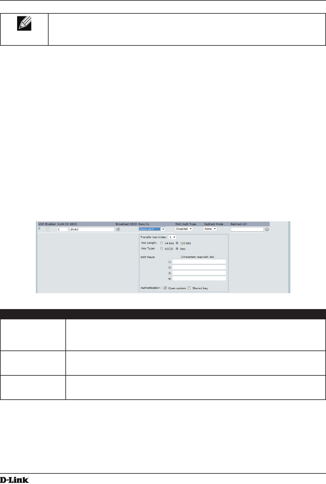
Unied Access Point Administrator’s Guide
Unied Access Point Administrator’s Guide
Page 50
May 2016
Section 4 - Managing the Access Point
Note: After you congure the VAP settings, you must click Apply to apply the changes and to save
the settings. Changing some settings might cause the AP to stop and restart system processes. If
this happens, wireless clients will temporarily lose connectivity. We recommend that you change
AP settings when WLAN trafc is low.
None (Plain-text)
If you select None as your security mode, no further options are congurable on the AP. This mode means that
any data transferred to and from the UAP is not encrypted. This security mode can be useful during initial network
conguration or for problem solving, but it is not recommended for regular use on the Internal network because it is
not secure.
Static WEP
Wired Equivalent Privacy (WEP) is a data encryption protocol for 802.11 wireless networks. All wireless stations and
APs on the network are congured with a static 64-bit (40-bit secret key + 24-bit initialization vector (IV)) or 128-bit
(104-bit secret key + 24-bit IV) Shared Key for data encryption.
Static WEP is not the most secure mode available, but it offers more protection than setting the security mode to None
(Plain-text) as it does prevent an outsider from easily snifng out unencrypted wireless trafc.
WEP encrypts data moving across the wireless network based on a static key. (The encryption algorithm is a stream
cipher called RC4.)
Figure 23 - Modify Virtual Access Point Settings (Static WEP)
Field Description
Transfer Key Index Select a key index from the drop-down menu. Key indexes 1 through 4 are available. The
default is 1.
The Transfer Key Index indicates which WEP key the AP will use to encrypt the data it
transmits.
Key Length Specify the length of the key by clicking one of the radio buttons:
•) 64 bits
•) 128 bits
Key Type Select the key type by clicking one of the radio buttons:
•) ASCII
•) Hex

Unied Access Point Administrator’s Guide
Unied Access Point Administrator’s Guide
Page 51
May 2016
Section 4 - Managing the Access Point
Field Description
WEP Keys You can specify up to four WEP keys. In each text box, enter a string of characters for each
key. The keys you enter depend on the key type selected:
•) ASCII — Includes upper and lower case alphabetic letters, the numeric digits, and
special symbols such as @ and #.
•) Hex — Includes digits 0 to 9 and the letters A to F.
Use the same number of characters for each key as specied in the Characters Required
eld. These are the RC4 WEP keys shared with the stations using the AP.
Each client station must be congured to use one of these same WEP keys in the same slot
as specied here on the AP.
Characters Required: The number of characters you enter into the WEP Key elds is
determined by the Key length and Key type you select. For example, if you use 128-bit
ASCII keys, you must enter 26 characters in the WEP key. The number of characters
required updates automatically based on how you set Key Length and Key Type.
Authentication The authentication algorithm denes the method used to determine whether a client station
is allowed to associate with an AP when static WEP is the security mode.
Specify the authentication algorithm you want to use by choosing one of the following
options:
•) Open System authentication allows any client station to associate with the AP whether
that client station has the correct WEP key or not. This algorithm is also used in
plaintext, IEEE 802.1X, and WPA modes. When the authentication algorithm is set to
Open System, any client can associate with the AP.
Note: Just because a client station is allowed to associate does not ensure it can exchange
trafc with an AP. A station must have the correct WEP key to be able to successfully access
and decrypt data from an AP, and to transmit readable data to the AP.
•) Shared Key authentication requires the client station to have the correct WEP key in
order to associate with the AP. When the authentication algorithm is set to Shared
Key, a station with an incorrect WEP key will not be able to associate with the AP.
•) Both Open System and Shared Key. When you select both authentication
algorithms:
•) Client stations congured to use WEP in shared key mode must have a valid WEP
key in order to associate with the AP.
•) Client stations congured to use WEP as an open system (shared key mode not
enabled) will be able to associate with the AP even if they do not have the correct
WEP key.
Table 23 - Static WEP
Static WEP Rules
If you use Static WEP, the following rules apply:
•) All client stations must have the Wireless LAN (WLAN) security set to WEP, and all clients must have one of the
WEP keys specied on the AP in order to de-code AP-to-station data transmissions.
•) The AP must have all keys used by clients for station-to-AP transmit so that it can de-code the station
transmissions.
•) The same key must occupy the same slot on all nodes (AP and clients). For example if the AP denes abc123
key as WEP key 3, then the client stations must dene that same string as WEP key 3.
•) Client stations can use different keys to transmit data to the access point. (Or they can all use the same key, but
this is less secure because it means one station can decrypt the data being sent by another.)
•) On some wireless client software, you can congure multiple WEP keys and dene a client station “transfer
key index”, and then set the stations to encrypt the data they transmit using different keys. This ensures that
neighboring APs cannot decode each other’s transmissions.
•) You cannot mix 64-bit and 128-bit WEP keys between the access point and its client stations.
IEEE 802.1X
IEEE 802.1X is the standard dening port-based authentication and infrastructure for doing key management.
Extensible Authentication Protocol (EAP) messages sent over an IEEE 802.11 wireless network using a protocol
called EAP Encapsulation Over LANs (EAPOL). IEEE 802.1X provides dynamically-generated keys that are
periodically refreshed. An RC4 stream cipher is used to encrypt the frame body and cyclic redundancy checking
(CRC) of each 802.11 frame.
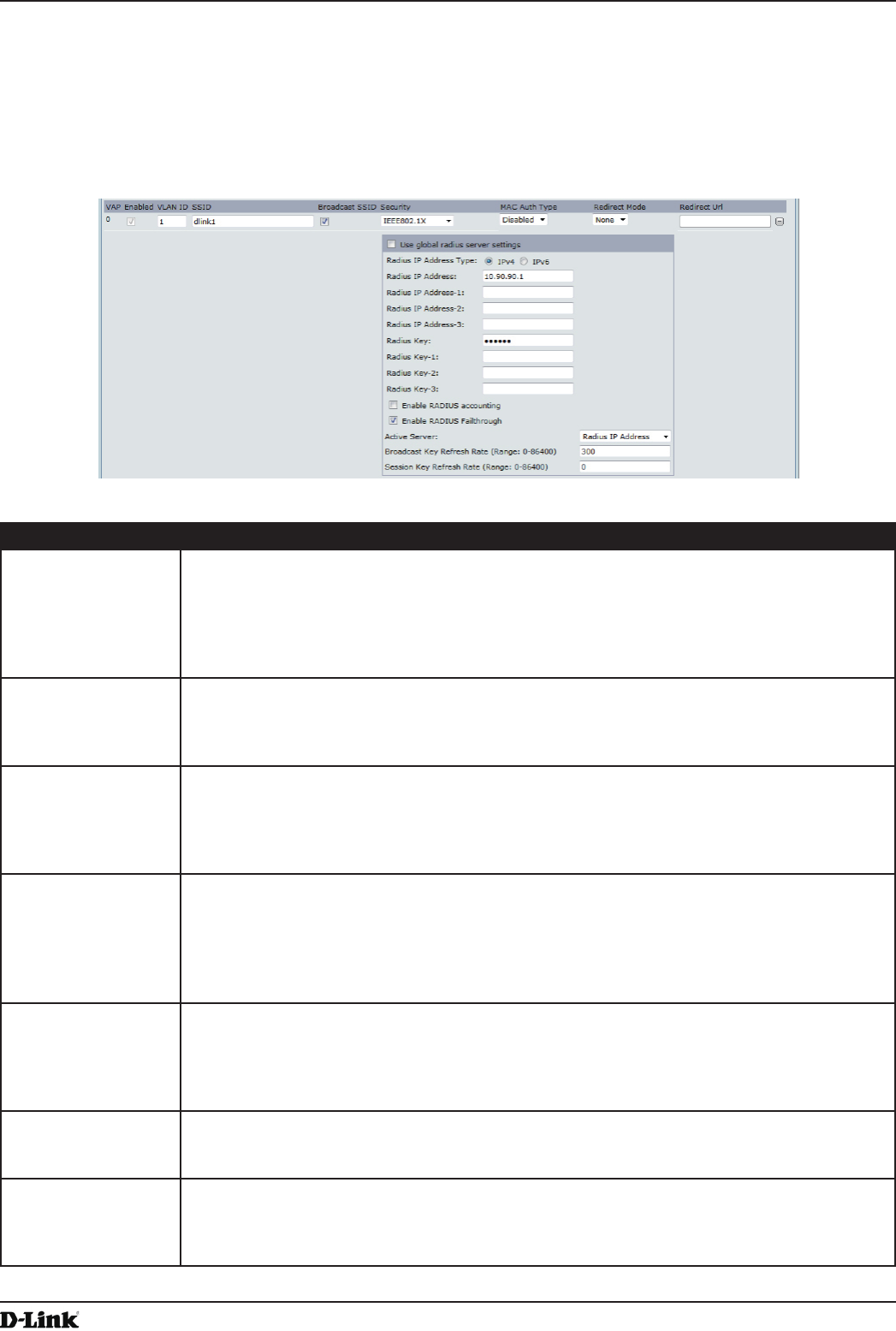
Unied Access Point Administrator’s Guide
Unied Access Point Administrator’s Guide
Page 52
May 2016
Section 4 - Managing the Access Point
This mode requires the use of an external RADIUS server to authenticate users. The AP requires a RADIUS server
capable of EAP, such as the Microsoft Internet Authentication Server. To work with Windows clients, the authentication
server must support Protected EAP (PEAP) and MSCHAP V2.
You can use any of a variety of authentication methods that the IEEE 802.1X mode supports, including certicates,
Kerberos, and public key authentication. You must congure the client stations to use the same authentication method
the AP uses.
Figure 24 - Modify Virtual Access Point Settings (IEEE802.1X)
Field Description
Use Global RADIUS
Server Settings
By default each VAP uses the global RADIUS settings that you dene for the AP at the top
of the VAP page. However, you can congure each VAP to use a different set of RADIUS
servers.
To use the global RADIUS server settings, make sure the check box is selected.
To use a separate RADIUS server for the VAP, clear the check box and enter the RADIUS
server IP address and key in the following elds.
RADIUS IP Address
Type
Specify the IP version that the RADIUS server uses.
You can toggle between the address types to congure IPv4 and IPv6 global RADIUS
address settings, but the AP contacts only the RADIUS server or servers for the address
type you select in this eld.
RADIUS IP Address
RADIUS IPv6
Address
Enter the IPv4 or IPv6 address for the primary RADIUS server for this VAP.
If the IPv4 RADIUS IP Address Type option is selected in the previous eld, enter the IP
address of the RADIUS server that all VAPs use by default, for example 192.168.10.23. If
the IPv6 RADIUS IP Address Type option is selected, enter the IPv6 address of the primary
global RADIUS server, for example 2001:0db8:1234::abcd.
RADIUS IP or IPv6
Address 1–3
Enter up to three IPv4 and/or IPv6 addresses to use as the backup RADIUS servers for this
VAP. The eld label is RADIUS IP Address when the IPv4 RADIUS IP Address Type option
is selected and RADIUS IPv6 Address when the IPv6 RADIUS IP Address Type option is
selected.
If authentication fails with the primary server, each congured backup server is tried in
sequence.
RADIUS Key Enter the RADIUS key in the text box.
The RADIUS Key is the shared secret key for the global RADIUS server. You can use up to
63 standard alphanumeric and special characters. The key is case sensitive, and you must
congure the same key on the AP and on your RADIUS server. The text you enter will be
displayed as “*” characters to prevent others from seeing the RADIUS key as you type.
RADIUS Key 1 – 3 Enter the RADIUS key associated with the congured backup RADIUS servers. The server
at RADIUS IP Address-1 uses RADIUS Key-1, RADIUS IP Address-2 uses RADIUS Key-2,
and so on.
Enable RADIUS
Accounting
Select this option to track and measure the resources a particular user has consumed
such as system time, amount of data transmitted and received, and so on.
If you enable RADIUS accounting, it is enabled for the primary RADIUS server and all
backup servers.
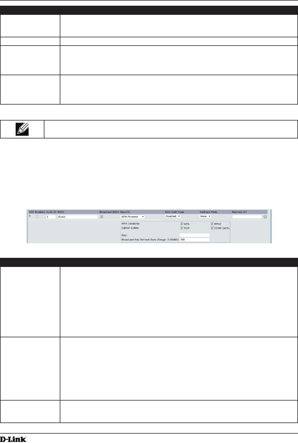
Unied Access Point Administrator’s Guide
Unied Access Point Administrator’s Guide
Page 53
May 2016
Section 4 - Managing the Access Point
Field Description
Enable RADIUS
FailThrough
Select this option to allow the secondary RADIUS server to authenticate wireless clients if
the authentication with the primary RADIUS server is unsuccessful, or if the primary RADIUS
server is unavailable.
Active Server Specify which congured RADIUS server to use as the active RADIUS server.
Broadcast Key
Refresh Rate
Enter a value to set the interval at which the broadcast (group) key is refreshed for clients
associated to this VAP (the default is 300).
The valid range is 0 – 86400 seconds. A value of 0 indicates that the broadcast key is not
refreshed.
Session Key
Refresh Rate
Enter a value to set the interval at which the AP will refresh session (unicast) keys for each
client associated to the VAP.
The valid range is 0 – 86400 seconds. A value of 0 indicates that the broadcast key is not
refreshed.
Table 24 - IEEE 802.1X
Note: After you congure the security settings, you must click Apply to apply the changes and to
save the settings.
WPA Personal
WPA Personal is a Wi-Fi Alliance IEEE 802.11i standard, which includes AES-CCMP and TKIP mechanisms. The
Personal version of WPA employs a pre-shared key (instead of using IEEE 802.1X and EAP as is used in the
Enterprise WPA security mode). The PSK is used for an initial check of credentials only.
This security mode is backwards-compatible for wireless clients that support the original WPA.
Figure 25 - Modify Virtual Access Point Settings (WPA Personal)
Field Description
WPA Versions Select the types of client stations you want to support:
•) WPA. If all client stations on the network support the original WPA but none support the
newer WPA2, then select WPA.
•) WPA2. If all client stations on the network support WPA2, we suggest using WPA2
which provides the best security per the IEEE 802.11i standard.
•) WPA and WPA2. If you have a mix of clients, some of which support WPA2 and others
which support only the original WPA, select both of the check boxes. This lets both
WPA and WPA2 client stations associate and authenticate, but uses the more robust
WPA2 for clients who support it. This WPA conguration allows more interoperability,
at the expense of some security.
Cipher Suites Select the cipher suite you want to use:
•) TKIP
•) CCMP (AES)
•) TKIP and CCMP (AES)
Both TKIP and AES clients can associate with the AP. WPA clients must have one of the
following to be able to associate with the AP:
•) A valid TKIP key
•) A valid AES-CCMP key
Clients not congured to use a WPA Personal will not be able to associate with the AP.
Key The Pre-shared Key is the shared secret key for WPA Personal. Enter a string of at least 8
characters to a maximum of 63 characters. Acceptable characters include upper and lower
case alphabetic letters, the numeric digits, and special symbols such as @ and #.
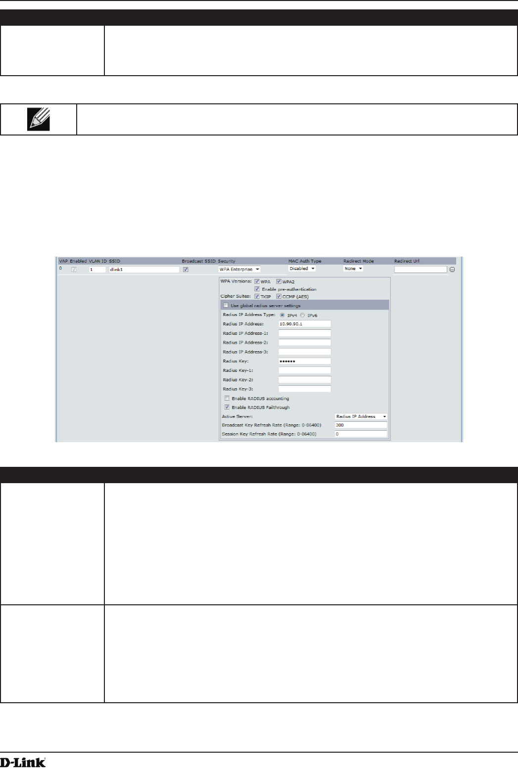
Unied Access Point Administrator’s Guide
Unied Access Point Administrator’s Guide
Page 54
May 2016
Section 4 - Managing the Access Point
Field Description
Broadcast Key
Refresh Rate
Enter a value to set the interval at which the broadcast (group) key is refreshed for clients
associated to this VAP (the default is 300).
The valid range is 0–86400 seconds. A value of 0 indicates that the broadcast key is not
refreshed.
Table 25 - WPA Personal
Note: After you congure the security settings, you must click Apply to apply the changes and to
save the settings.
WPA Enterprise
WPA Enterprise with RADIUS is an implementation of the Wi-Fi Alliance IEEE 802.11i standard, which includes CCMP
(AES), and TKIP mechanisms. The Enterprise mode requires the use of a RADIUS server to authenticate users.
This security mode is backwards-compatible with wireless clients that support the original WPA.
Figure 26 - Modify Virtual Access Point Settings (WPA Enterprise)
Field Description
WPA Versions Select the types of client stations you want to support:
•) WPA. If all client stations on the network support the original WPA but none support the
newer WPA2, then select WPA.
•) WPA2. If all client stations on the network support WPA2, we suggest using WPA2
which provides the best security per the IEEE 802.11i standard.
•) WPA and WPA2. If you have a mix of clients, some of which support WPA2 and others
which support only the original WPA, select both WPA and WPA2. This lets both WPA
and WPA2 client stations associate and authenticate, but uses the more robust WPA2
for clients who support it. This WPA conguration allows more interoperability, at the
expense of some security.
Enable pre-
authentication
If for WPA Versions you select only WPA2 or both WPA and WPA2, you can enable pre-
authentication for WPA2 clients.
Click Enable pre-authentication if you want WPA2 wireless clients to send pre-
authentication packet. The pre-authentication information will be relayed from the AP
the client is currently using to the target AP. Enabling this feature can help speed up
authentication for roaming clients who connect to multiple APs.
This option does not apply if you selected WPA for WPA Versions because the original WPA
does not support this feature.

Unied Access Point Administrator’s Guide
Unied Access Point Administrator’s Guide
Page 55
May 2016
Section 4 - Managing the Access Point
Field Description
Cipher Suites Select the cipher suite you want to use:
•) TKIP
•) CCMP (AES)
•) TKIP and CCMP (AES)
By default both TKIP and CCMP are selected. When both TKIP and CCMP are selected,
client stations congured to use WPA with RADIUS must have one of the following:
•) A valid TKIP RADIUS IP address and RADIUS Key
•) A valid CCMP (AES) IP address and RADIUS Key
Use Global RADIUS
Server Settings
By default each VAP uses the global RADIUS settings that you dene for the AP at the top
of the VAP page. However, you can congure each VAP to use a different set of RADIUS
servers.
To use the global RADIUS server settings, make sure the check box is selected.
To use a separate RADIUS server for the VAP, clear the check box and enter the RADIUS
server IP address and key in the following elds.
RADIUS IP Address
Type
Specify the IP version that the RADIUS server uses.
You can toggle between the address types to congure IPv4 and IPv6 global RADIUS
address settings, but the AP contacts only the RADIUS server or servers for the address
type you select in this eld.
RADIUS IP Address
RADIUS IPv6
Address
Enter the IPv4 or IPv6 address for the primary RADIUS server for this VAP.
If the IPv4 RADIUS IP Address Type option is selected in the previous eld, enter the IP
address of the RADIUS server that all VAPs use by default, for example 192.168.10.23.
If the IPv6 RADIUS IP Address Type option is selected, enter the IPv6 address of the
primary global RADIUS server, for example 2001:0db8:1234::abcd.
RADIUS IP or IPv6
Address 1–3
Enter up to three IPv4 and/or IPv6 addresses to use as the backup RADIUS servers for this
VAP. The eld label is RADIUS IP Address when the IPv4 RADIUS IP Address Type option
is selected and RADIUS IPv6 Address when the IPv6 RADIUS IP Address Type option is
selected.
If authentication fails with the primary server, each congured backup server is tried in
sequence.
RADIUS Key Enter the RADIUS key in the text box.
The RADIUS Key is the shared secret key for the global RADIUS server. You can use up to
63 standard alphanumeric and special characters. The key is case sensitive, and you must
congure the same key on the AP and on your RADIUS server. The text you enter will be
displayed as “*” characters to prevent others from seeing the RADIUS key as you type.
RADIUS Key 1–3 Enter the RADIUS key associated with the congured backup RADIUS servers. The server
at RADIUS IP Address-1 uses RADIUS Key-1, RADIUS IP Address-2 uses RADIUS Key-2,
and so on.
Enable RADIUS
Accounting
Select this option to track and measure the resources a particular user has consumed
such as system time, amount of data transmitted and received, and so on.
If you enable RADIUS accounting, it is enabled for the primary RADIUS server and all
backup servers.
Enable RADIUS
FailThrough
Select this option to allow the secondary RADIUS server to authenticate wireless clients
if the authentication with the primary RADIUS server is unsuccessful, or if the primary
RADIUS server is unavailable.
Active Server Specify which congured RADIUS server to use as the active RADIUS server.
Broadcast Key
Refresh Rate
Enter a value to set the interval at which the broadcast (group) key is refreshed for clients
associated to this VAP (the default is 300).
The valid range is 0–86400 seconds. A value of 0 indicates that the broadcast key is not
refreshed.
Session Key
Refresh Rate
Enter a value to set the interval at which the AP will refresh session (unicast) keys for each
client associated to the VAP.
The valid range is 0–86400 seconds. A value of 0 indicates that the broadcast key is not
refreshed.
Table 26 - WPA Enterprise
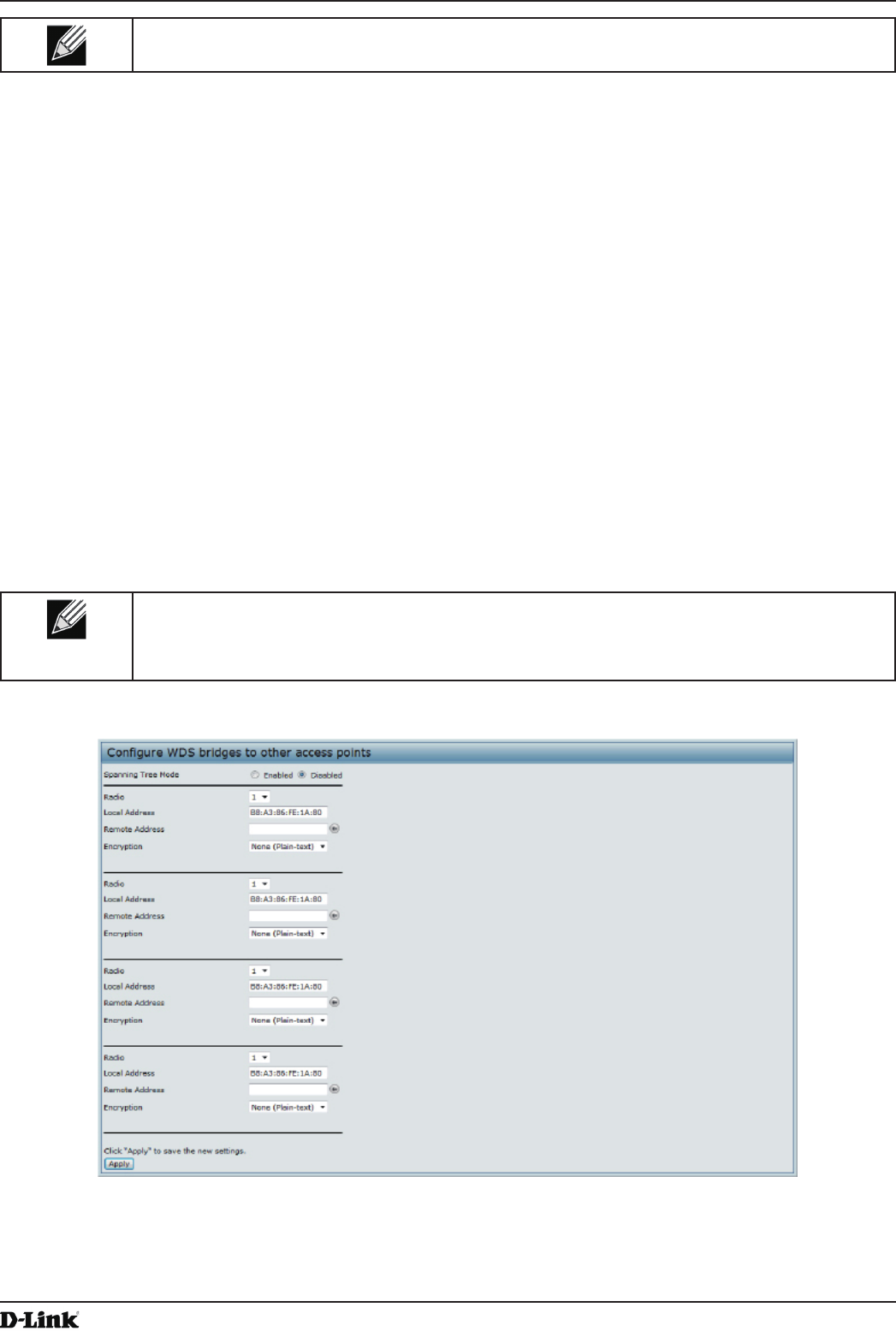
Unied Access Point Administrator’s Guide
Unied Access Point Administrator’s Guide
Page 56
May 2016
Section 4 - Managing the Access Point
Note: After you congure the security settings, you must click Apply to apply the changes and to
save the settings.
Conguring the Wireless Distribution System (WDS)
The Wireless Distribution System (WDS) allows you to connect multiple UAPs. With WDS, APs communicate with one
another without wires in a standardized way. This capability is critical in providing a seamless experience for roaming
clients and for managing multiple wireless networks. It can also simplify the network infrastructure by reducing the
amount of cabling required. You can congure the AP in point-to-point or point-to-multipoint bridge mode based on the
number of links to connect.
In the point-to-point mode, the AP accepts client associations and communicates with wireless clients and other
repeaters. The AP forwards all trafc meant for the other network over the tunnel that is established between the APs.
The bridge does not add to the hop count. It functions as a simple OSI layer 2 network device.
In the point-to-multipoint bridge mode, one AP acts as the common link between multiple APs. In this mode, the
central AP accepts client associations and communicates with the clients and other repeaters. All other APs associate
only with the central AP that forwards the packets to the appropriate wireless bridge for routing purposes.
The UAP can also act as a repeater. In this mode, the AP serves as a connection between two APs that might be
too far apart to be within cell range. When acting as a repeater, the AP does not have a wired connection to the LAN
and repeats signals by using the wireless connection. No special conguration is required for the AP to function as a
repeater, and there are no repeater mode settings. Wireless clients can still connect to an AP that is operating as a
repeater.
Note: When you move an AP from Standalone Mode to Managed Mode, WDS is disabled.
In Managed Mode, you congure the AP by using the D-Link Unied Wireless Switch. The
Administrator UI, as well as Telnet, SSH, and SNMP access are disabled when the AP is in
Managed Mode.
To specify the details of trafc exchange from this access point to others, click the WDS tab.
Figure 27 - Congure WDS Bridges
Before you congure WDS on the AP, note the following guidelines:
•) When using WDS, be sure to congure WDS settings on both APs participating in the WDS link.
•) You can have only one WDS link between any pair of APs. That is, a remote MAC address may appear only
once on the WDS page for a particular AP.
Unied Access Point Administrator’s Guide
Unied Access Point Administrator’s Guide
Page 57
May 2016
Section 4 - Managing the Access Point
•) Both APs participating in a WDS link must be on the same Radio channel and using the same IEEE 802.11
mode. (See “Modifying Radio Settings” on page 40 for information on conguring the Radio mode and
channel.)
•) When 802.11h is operational, setting up two WDS links can be difcult.
To congure WDS on this AP, describe each AP intended to receive handoffs and send information to this AP. For each
destination AP, congure the elds listed in the table below.
Field Description
Spanning Tree
Mode
Spanning Tree Protocol (STP) prevents switching loops. STP is recommended if you
congure WDS links.
Select Enabled to use STP
Select Disabled to turn off STP links (not recommended)
Radio For each WDS link on a two-radio AP, select Radio One or Radio Two. The rest of the
settings for the link apply to the radio selected in this eld. The read-only Local Address will
change depending on which Radio you select in this eld.
Local Address Indicates the MAC addresses for this AP.
For each WDS link on a two-radio AP, the Local Address reects the MAC address for the
internal interface on the selected radio (Radio One on wlan0 or Radio Two on wlan1).
Remote Address Specify the MAC address of the destination AP; that is, the AP on the other end of the WDS
link to which data will be sent or handed-off and from which data will be received.
Click the drop-down arrow to the right of the Remote Address eld to see a list of all the
available MAC Addresses and their associated SSIDs on the network. Select the appropriate
MAC address from the list.
Note: The SSID displayed in the drop-down list is simply to help you identify the correct
MAC Address for the destination AP. This SSID is a separate SSID to that which you set for
the WDS link. The two do not (and should not) be the same value or name.
Encryption You can use no encryption, WEP, or WPA (PSK) on the WDS link.
If you are unconcerned about security issues on the WDS link you may decide not to set
any type of encryption. Alternatively, if you have security concerns you can choose between
Static WEP and WPA (PSK). In WPA (PSK) mode, the AP uses WPA2-PSK with CCMP
(AES) encryption over the WDS link.
Table 27 - WDS Settings
If you select None as your preferred WDS encryption option, you will not be asked to ll in any more elds on the
WDS page. All data transferred between the two APs on the WDS link will be unencrypted.
Note: To disable a WDS link, you must remove the value congured in the Remote Address eld.
WEP on WDS Links
The following table describes the additional elds that appear when you select WEP as the encryption type.
Field Description
Encryption WEP
WEP Select this option if you want to set WEP encryption on the WDS link.
Key Length If WEP is enabled, specify the length of the WEP key:
•) 64 bits
•) 128 bits
Key Type If WEP is enabled, specify the WEP key type:
•) ASCII
•) Hex
Unied Access Point Administrator’s Guide
Unied Access Point Administrator’s Guide
Page 58
May 2016
Section 4 - Managing the Access Point
Field Description
Characters
Required
Indicates the number of characters required in the WEP key.
The number of characters required updates automatically based on how you set Key Length
and Key Type.
WEP Key Enter a string of characters. If you selected ASCII, enter any combination of 0 – 9, a – z, and
A – Z. If you selected HEX, enter hexadecimal digits (any combination of 0 – 9 and a – f or
A – F). These are the RC4 encryption keys shared with the stations using the AP.
Table 28 - WEP on WDS Links
WPA/PSK on WDS Links
The following table describes the aAdditional elds that appear when you select WPA/PSK as the encryption type.
Field Description
Encryption WPA (PSK)
SSID Enter an appropriate name for the new WDS link you have created. This SSID should be
different from the other SSIDs used by this AP. However, it is important that the same SSID
is also entered at the other end of the WDS link. If this SSID is not the same for both APs on
the WDS link, they will not be able to communicate and exchange data.
The SSID can be any alphanumeric combination.
Key Enter a unique shared key for the WDS bridge. This unique shared key must also be
entered for the AP at the other end of the WDS link. If this key is not the same for both APs,
they will not be able to communicate and exchange data.
The WPA-PSK key is a string of at least 8 characters to a maximum of 63 characters.
Acceptable characters include upper and lower case alphabetic letters, the numeric digits,
and special symbols such as @ and #.
Table 29 - WPA/PSK on WDS Links
Note: After you congure the WDS settings, you must click Apply to apply the changes and
to save the settings. Changing some settings might cause the AP to stop and restart system
processes. If this happens, wireless clients will temporarily lose connectivity. We recommend that
you change AP settings when WLAN trafc is low.
Controlling Access by MAC Authentication
A Media Access Control (MAC) address is a hardware address that uniquely identies each node of a network.
All IEEE 802 network devices share a common 48-bit MAC address format, usually displayed as a string of 12
hexadecimal digits separated by colons, for example 00:DC:BA:09:87:65. Each wireless network interface card (NIC)
used by a wireless client has a unique MAC address.
You can use the Administrator UI on the AP or use an external RADIUS server to control access to the network
through the AP based on the MAC address of the wireless client. This feature is called MAC Authentication or MAC
Filtering. To control access, you congure a global list of MAC addresses locally on the AP or on an external RADIUS
server. Then, you set a lter to specify whether the clients with those MAC addresses are allowed or denied access to
the network. When a wireless client attempts to associate with an AP, the AP looks up the MAC address of the client
in the local Stations List or on the RADIUS server. If it is found, the global allow or deny setting is applied. If it is not
found, the opposite is applied.
On the VAP page, the MAC Authentication Type setting controls whether the AP uses the station list congured
locally on the MAC Authentication page or the external RADIUS server. The Allow/Block lter setting on the MAC
Authentication page determines whether the clients in the station list (local or RADIUS) can access the network
through the AP. For more information about setting the MAC authentication type, see “Virtual Access Point Settings”
on page 47.
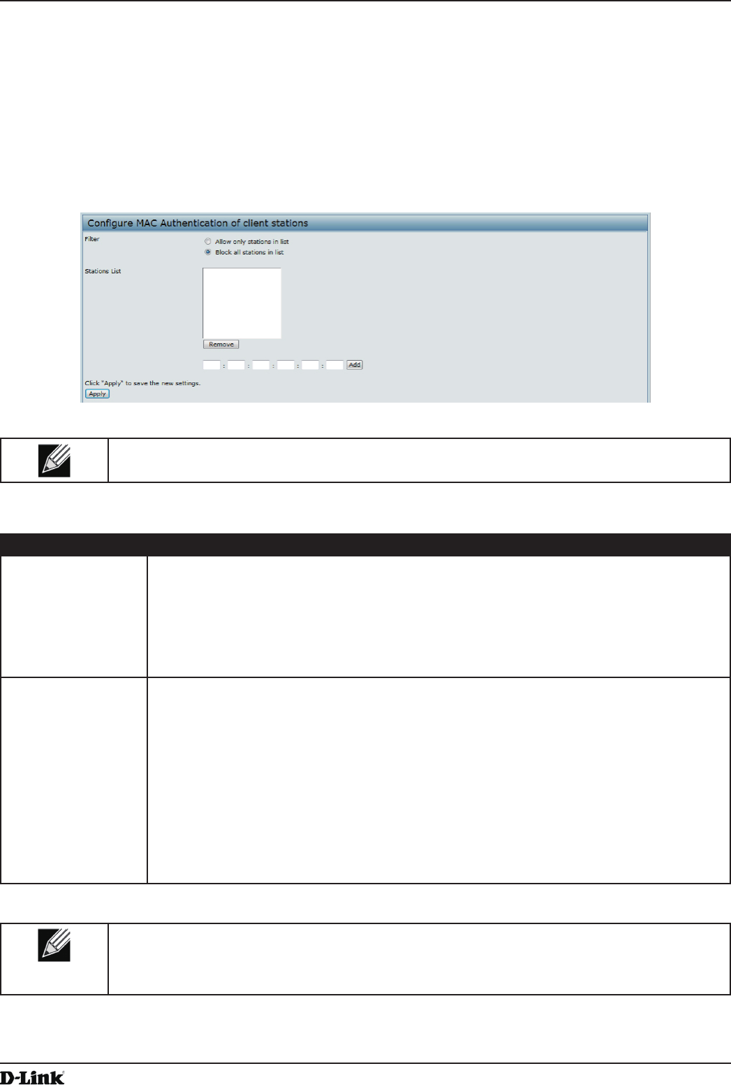
Unied Access Point Administrator’s Guide
Unied Access Point Administrator’s Guide
Page 59
May 2016
Section 4 - Managing the Access Point
Conguring a MAC Filter and Station List on the AP
The MAC Authentication page allows you to control access to UAP based on MAC addresses. Based on how you
set the lter, you can allow only client stations with a listed MAC address or deny access to the stations listed.
When you enable MAC Authentication and specify a list of approved MAC addresses, only clients with a listed MAC
address can access the network. If you specify MAC addresses to deny, all clients can access the network except for
the clients on the deny list.
To enable ltering by MAC address, click the MAC Authentication tab.
Figure 28 - Congure MAC Authentication
Note: Global MAC Authentication settings apply to all VAPs on all supported radios.
The following table describes the elds and conguration options available on the MAC Authentication page.
Field Description
Filter To set the MAC Address Filter, select one of the following options:
•) Allow only stations in the list. Any station that is not in the Stations List is denied
access to the network through the AP.
•) Block all stations in list. Only the stations that appear in the list are denied access to
the network through the AP. All other stations are permitted access.
Note: The lter you select is applied to the clients in the station list, regardless of whether
that station list is local or on the RADIUS server.
Stations List This is the local list of clients that are either permitted or denied access to the network
through the AP. To add a MAC Address to the local Stations List, enter its 48-bit MAC
address into the lower text boxes, then click Add.
To remove a MAC Address from the Stations List, select its 48-bit MAC address, then click
Remove.
The stations in the list will either be allowed or denied access based on how you set the lter
in the previous eld.
Note: If the MAC authentication type for the VAP is set to Local, the AP uses the Stations
List to permit or deny the clients access to the network. If the MAC authentication type is set
to RADIUS, the AP ignores the MAC addresses congured in this list and uses the list that is
stored on the RADIUS server. The MAC authentication type is set on the VAP conguration
page.
Table 30 - MAC Authentication
Note: After you congure local MAC Authentication settings, you must click Apply to apply the
changes and to save the settings. Changing some settings might cause the AP to stop and
restart system processes. If this happens, wireless clients will temporarily lose connectivity. We
recommend that you change AP settings when WLAN trafc is low.
Conguring MAC Authentication on the RADIUS Server
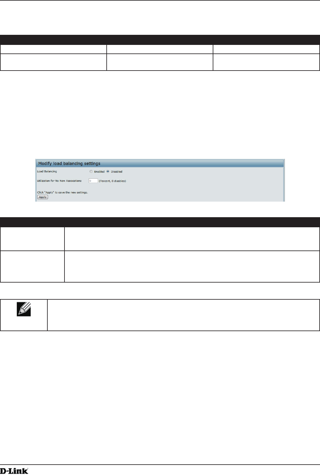
Unied Access Point Administrator’s Guide
Unied Access Point Administrator’s Guide
Page 60
May 2016
Section 4 - Managing the Access Point
If you use RADIUS MAC authentication for MAC-based access control, you must congure a station list on the
RADIUS server. The station list contains client MAC address entries, and the format for the list is described in the
following table.
RADIUS Server Attribute Description Value
User-Name (1) MAC address of the client station. Valid Ethernet MAC Address.
User-Password (2) A xed global password used to
lookup a client MAC entry.
NOPASSWORD
Table 31 - RADIUS Server Attributes for MAC Authentication
Conguring Load Balancing
You can set network utilization thresholds on the UAP to maintain the speed and performance of the wireless network
as clients associate and disassociate with the AP. The load balancing settings apply to all supported radios.
To congure load balancing and set limits and behavior to be triggered by a specied utilization rate of the access
point, click the Load Balancing tab and update the elds shown in the following gure.
Figure 29 - Modify Load Balancing Settings
Field Description
Load Balancing Enable or disable load balancing:
To enable load balancing on this AP, click Enable.
To disable load balancing on this AP, click Disable.
Utilization for No
New Associations
Provide the percentage of network bandwidth utilization allowed on the radio before the AP
stops accepting new client associations.
The default is 0, which means that all new associations will be allowed regardless of the
utilization rate.
Table 32 - Load Balancing
Note: After you congure the load balancing settings, you must click Apply to apply the changes
and to save the settings. Changing some settings might cause the AP to stop and restart system
processes. If this happens, wireless clients will temporarily lose connectivity. We recommend that
you change AP settings when WLAN trafc is low.
Managed Access Point Overview
The UAP can operate in two modes: Standalone Mode or Managed Mode. In Standalone Mode, the UAP acts as
an individual AP in the network, and you manage it by using the Administrator Web User Interface (UI), CLI, or SNMP.
In Managed Mode, the UAP is part of the D-Link Unied Wired and Wireless System, and you manage it by using
the D-Link Unied Wireless Switch. If an AP is in Managed Mode, the Administrator Web UI, Telnet, SSH, and SNMP
services are disabled.
On the UAP, you can congure the IP addresses of up to four D-Link Unied Wireless Switches that can manage it. In
order to manage the AP, the switch and AP must discover each other. There are multiple ways for a switch to discover
an AP. Adding the IP address of the switch to the AP while it is in Standalone Mode is one way to enable switch-to-AP
discovery.
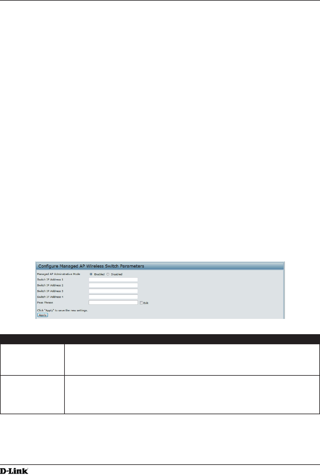
Unied Access Point Administrator’s Guide
Unied Access Point Administrator’s Guide
Page 61
May 2016
Section 4 - Managing the Access Point
Transitioning Between Modes
Every 30 seconds, the D-Link Unied Wireless Switch sends a keepalive message to all of the access points it
manages. Each AP checks for the keepalive messages on the SSL TCP connection. As long as the AP maintains
communication with the switch through the keepalive messages, it remains in Managed Mode.
If the AP does not receive a message within 45 seconds of the last keepalive message, the AP assumes the switch
has failed and terminates its TCP connection to the switch, and the AP enters Standalone Mode.
Once the AP transitions to Standalone Mode, it continues to forward trafc without any loss. The AP uses the
conguration on the VAPs congured in VLAN Forwarding mode (the standard, non-tunneled mode).
While the AP is in Standalone Mode, you can manage it by using the Web interface or the CLI (through Telnet or
SSH).
For any clients that are connected to the AP through tunneled VAPs, the AP sends disassociate messages and
disables the tunneled VAPs.
As long as the Managed AP Administrative Mode is set to Enabled, the AP starts discovery procedures. If the AP
establishes a connection with a wireless switch, which may or may not be the same switch it was connected to
before, the switch sends the AP its conguration and the AP sends the wireless switch information about all currently
associated clients.
After the conguration from the switch is applied, the AP radio(s) restart. Client trafc is briey interrupted until the
radio(s) are up and the clients are re-associated.
Conguring Managed Access Point Settings
To add the IP address of a D-Link Unied Wireless Switch to the AP, click the Managed Access Point tab under the
Manage heading and update the elds shown in the table below.
Figure 30 - Congure Managed AP Wireless Switch Parameters
Field Description
Managed AP
Administrative
Mode
Click Enabled to allow the AP and switch to discover each other. If the AP successfully
authenticates itself with a wireless switch, you will not be able to access the Administrator
UI.
Click Disabled to prevent the AP from contacting wireless switches.
Switch IP Address
(1-4)
Enter the IP address of up to four wireless switches that can manage the AP. You can
enter the IP address in dotted format or as an DNS name.
You can view a list of wireless switches on your network that were congured by using a
DHCP server.
The AP attempts to contact Switch IP Address 1 rst.
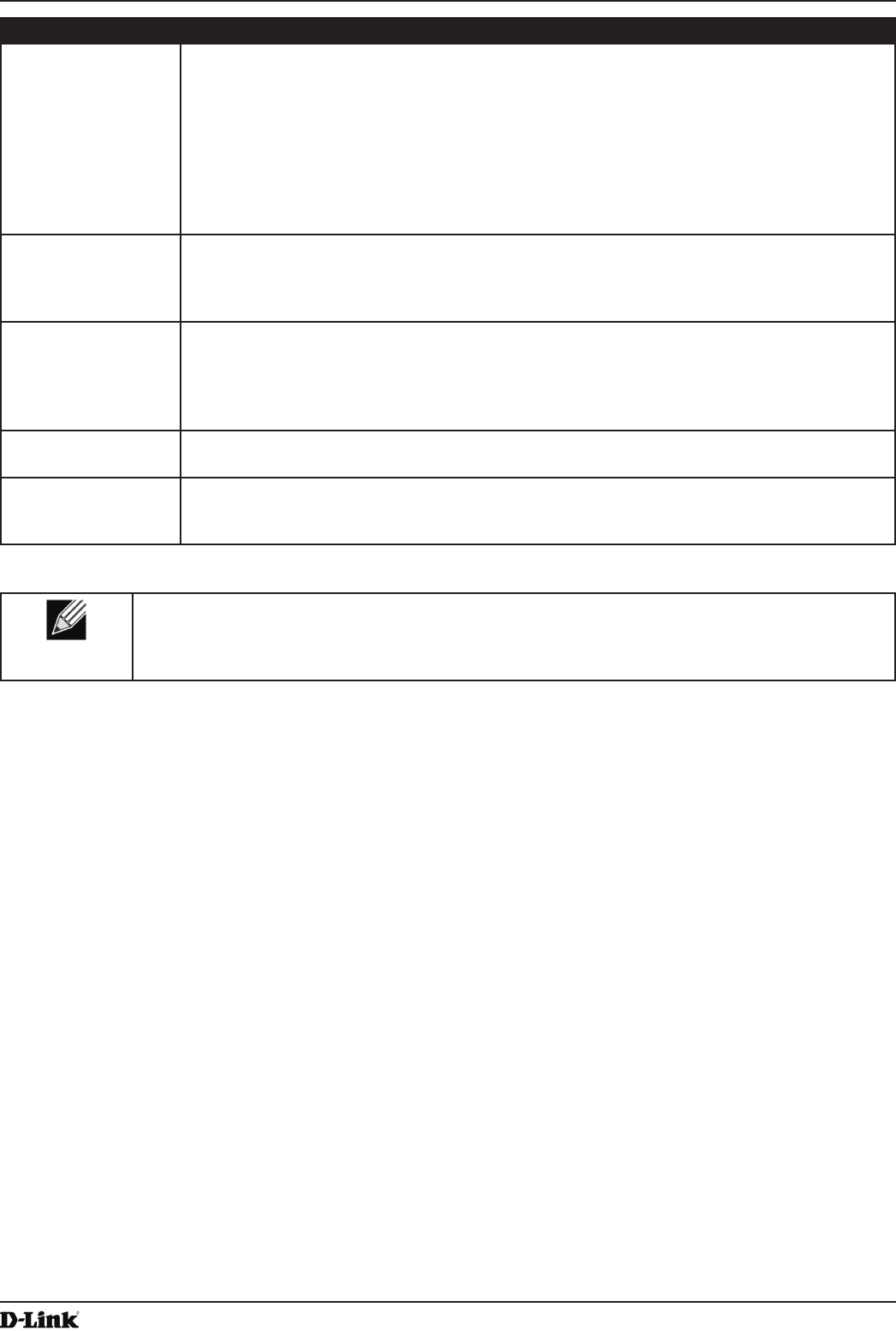
Unied Access Point Administrator’s Guide
Unied Access Point Administrator’s Guide
Page 62
May 2016
Section 4 - Managing the Access Point
Field Description
Base IP Port The starting IP port number used by the wireless feature (in a range of 10 consecutive port
numbers). Only the rst number in the range is congurable. The default value is 57775
(through 57784).
Note: When the wireless Base IP Port number is changed on the switch, the wireless
feature is automatically disabled and re-enabled. The new value is not sent as part of the
global switch conguration in the cluster conguration distribution command; every switch in
the cluster must be congured independently with the new Wireless IP port number.
Note: When the wireless Base IP Port number is changed from its default value on the
switch, it must also be changed on the Access Points.
Pass Phrase Select the Edit option and enter a passphrase to allow the AP to authenticate itself with the
wireless switch. The passphrase must be between 8 and 63 characters.
To remove the password, select Edit, delete the existing password, and then click Apply.
You must congure the same passphrase on the switch.
WDS Managed
Mode
Specify whether the AP will act as a Root AP or Satellite AP within the WDS group:
•) Root AP — Acts as a bridge or repeater on the wireless medium and communicates
with the switch via the wired link.
•) Satellite AP — Communicates with the switch via a WDS link to the Root AP. This
mode enables the Satellite AP to discover and establish WDS link with the Root AP.
WDS Managed
Ethernet Port
Specify whether the Ethernet port is to be enabled or disabled when the AP becomes part
of a WDS group.
WDS Group
Password
Password for WPA2 Personal authentication used to establish the WDS links. Only the
Satellite APs need this conguration. The Root APs get the password from the switch when
they become managed.
Table 33 - Managed Access Point
Note: After you congure the settings on the Managed Access Point page, you must click Apply
to apply the changes and to save the settings. Changing some settings might cause the AP to stop
and restart system processes. If this happens, wireless clients will temporarily lose connectivity.
We recommend that you change AP settings when WLAN trafc is low.
If the UAP successfully authenticates with a D-Link Unied Wireless Switch, you will loose access to the AP through
the Administrator UI.
Conguring 802.1X Authentication
On networks that use IEEE 802.1X, port-based network access control, a supplicant (client) cannot gain access to
the network until the 802.1X authenticator grants access. If your network uses 802.1X, you must congure 802.1X
authentication information that the AP can supply to the authenticator.
To congure the UAP 802.1X supplicant user name and password by using the Web interface, click the
Authentication tab and congure the elds shown in the table below.
Unied Access Point Administrator’s Guide
Unied Access Point Administrator’s Guide
Page 63
May 2016
Section 4 - Managing the Access Point
Figure 31 - Modify 802.1X Supplicant Authentication Settings
Field Description
802.1X Supplicant Click Enabled to enable the Administrative status of the 802.1X Supplicant.
Click Disabled to disable the Administrative status of the 802.1X Supplicant.
EAP Method Select one of the following EAP methods to use for communication between the AP and the
authenticator:
•) MD5
•) PEAP
•) TLS
Username Enter the user name for the AP to use when responding to requests from an 802.1X
authenticator.
The user name can be 1 to 64 characters in length. ASCII printable characters are allowed,
which includes upper and lower case alphabetic letters, the numeric digits, and special
symbols such as @ and #.
Password Enter the password for the AP to use when responding to requests from an 802.1X
authenticator.
The password can be 1 to 64 characters in length. ASCII printable characters are allowed,
which includes upper and lower case letters, numbers, and special symbols such as @ and
#.
Certicate File
Status
Indicates whether a certicate le is present and when that certicate expires.
Certicate File
Upload
Upload a certicate le to the AP by using HTTP or TFTP:
•) HTTP — Browse to the location where the certicate le is stored and click Upload.
•) TFTP — Specify the IP address of the TFTP server where the certicate le is located
and provide the le name, including the le path, then click Upload.
Table 34 - IEEE 802.1X Supplicant Authentication
Note: After you congure the settings on the Authentication page, you must click Apply to apply
the changes and to save the settings. Changing some settings might cause the AP to stop and
restart system processes. If this happens, wireless clients will temporarily lose connectivity. We
recommend that you change AP settings when WLAN trafc is low.
Creating a Management Access Control List (ACL)
You can create an access control list (ACL) that lists up to ve IPv4 hosts and ve IPv6 hosts that are authorized to
access the AP management interface. If this feature is disabled, anyone can access the management interface from
any network client by supplying the correct AP username and password.
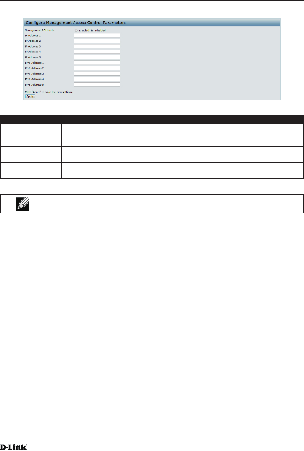
Unied Access Point Administrator’s Guide
Unied Access Point Administrator’s Guide
Page 64
May 2016
Section 4 - Managing the Access Point
To create an access list, click the Management ACL tab.
Figure 32 - Congure Management Access Control Parameters
Field Description
Management ACL
Mode
Enable or disable the management ACL feature. At least one IPv4 address should be
congured before enabling Management ACL Mode. If enabled, only the IP addresses you
specify will have Web, Telnet, SSH, and SNMP access to the management interface.
IP Address (1–5) Enter up to ve IPv4 addresses that are allowed management access to the AP. Use
dotted-decimal format (for example, 192.168.10.10).
IPv6 Address (1–5) Enter up to ve IPv6 addresses that are allowed management access to the AP. Use the
standard IPv6 address format (for example 2001:0db8:1234::abcd).
Table 35 - Management ACL
Note: After you congure the settings, click Apply to apply the changes and to save the settings.
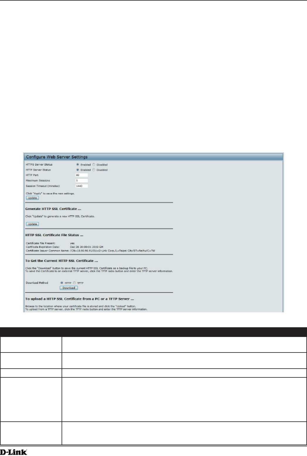
Unied Access Point Administrator’s Guide
Unied Access Point Administrator’s Guide
Page 65
May 2016
Section 5 - Conguring Access Point Services
Section 5 - Conguring Access Point Services
This section describes how to congure services on the UAP and contains the following subsections:
•) “Web Server Settings” on page 65
•) “Conguring SNMP on the Access Point” on page 66
•) “Setting the SSH Status” on page 68
•) “Setting the Telnet Status” on page 69
•) “Conguring Quality of Service” on page 69
•) “Conguring Email Alert” on page 72
•) “Enabling the Time Settings (NTP)” on page 73
Web Server Settings
The AP can be managed through HTTP or secure HTTP (HTTPS) sessions. By default both HTTP and HTTPS access
are enabled. Either access type can be disabled separately.
To congure Web server settings, click Web Server tab.
Figure 33 - Congure Web Server Settings
Field Description
HTTPS Server
Status
Enable or disable access through a Secure HTTP Server (HTTPS).
HTTP Server Status Enable or disable access through HTTP. This setting is independent of the HTTPS server
status setting.
HTTP Port Specify the port number for HTTP trafc (default is 80).
Maximum Sessions When a user logs on to the AP web interface, a session is created. This session is
maintained until the user logs off or the session inactivity timer expires.
Enter the number web sessions, including both HTTP and HTTPs, that can exist at the same
time. The range is 1–10 sessions. If the maximum number of sessions is reached, the next
user who attempts to log on to the AP web interface receives an error message about the
session limit.
Session Timeout Enter the maximum amount of time, in minutes, an inactive user remains logged on to the
AP web interface. When the congured timeout is reached, the user is automatically logged
off the AP. The range is 1–1440 minutes (1440 minutes = 1 day).
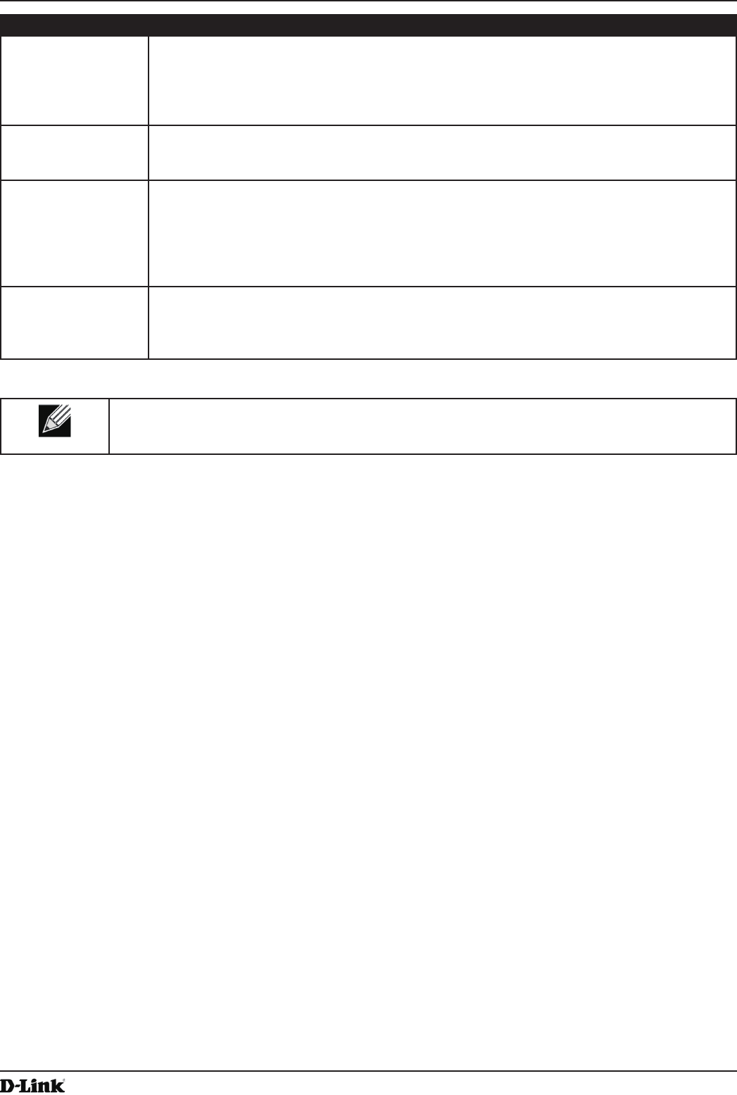
Unied Access Point Administrator’s Guide
Unied Access Point Administrator’s Guide
Page 66
May 2016
Section 5 - Conguring Access Point Services
Field Description
Generate HTTP SSL
Certicate
Select this option to generate a new SSL certicate for the secure Web server. This should
be done once the access point has an IP address to ensure that the common name for the
certicate matches the IP address of the UAP. Generating a new SSL certicate will restart
the secure Web server. The secure connection will not work until the new certicate is
accepted on the browser. Click the Update button to generate the new SSL certicate.
HTTP SSL
Certicate File
Status
Indicates whether a certicate le is present and species its expiration date and issuer
common name.
To Get the
Current HTTP SSL
Certicate
Save a copy of the current HTTP SSL certicate on a local system or TFTP server.
•) HTTP — Click Download and specify where to store the backup copy of the certicate
le.
•) TFTP — Provide a le name for the certicate le, including the le path, specify the
IP address of the TFTP server where the certicate le copy is to be stored, and then
click Download.
To upload a HTTP
SSL Certicate
from a PC or a TFTP
Server
Upload a certicate le to the AP by using HTTP or TFTP:
•) HTTP — Browse to the location where the certicate le is stored and click Upload.
•) TFTP — Specify the IP address of the TFTP server where the certicate le is located
and provide the le name, including the le path, then click Upload.
Table 36 - Web Server Settings
Note: Click Apply to apply the changes and to save the settings. If you disable the protocol you
are currently using to access the AP management interface, the current connection will end and
you will not be able to access the AP by using that protocol until it is enabled.
Conguring SNMP on the Access Point
Simple Network Management Protocol (SNMP) denes a standard for recording, storing, and sharing information
about network devices. SNMP facilitates network management, troubleshooting, and maintenance. The AP supports
SNMP versions 1, 2, and 3. Unless specically noted, all conguration parameters on this page apply to SNMPv1 and
SNMPv2c only.
Key components of any SNMP-managed network are managed devices, SNMP agents, and a management system.
The agents store data about their devices in Management Information Bases (MIBs) and return this data to the SNMP
manager when requested. Managed devices can be network nodes such as APs, routers, switches, bridges, hubs,
servers, or printers.
The UAP can function as an SNMP managed device for seamless integration into network management systems such
as HP OpenView.
From the SNMP page under the Services heading, you can start or stop control of SNMP agents, congure community
passwords, access MIBs, and congure SNMP Trap destinations.
From the pages under the SNMPv3 heading, you can manage SNMPv3 users and their security levels and dene
access control to the SNMP MIBs. For information about how to congure SNMPv3 views, groups, users, and targets,
see “Section 6 - Conguring SNMPv3” on page 75.
To congure SNMP, click the SNMP tab under the Services heading and update the elds described in the table
below.
Unied Access Point Administrator’s Guide
Unied Access Point Administrator’s Guide
Page 67
May 2016
Section 5 - Conguring Access Point Services
Figure 34 - SNMP Conguration
Field Description
SNMP Enabled/
Disabled
You can specify the SNMP administrative mode on your network. By default SNMP is
enabled. To enable SNMP, click Enabled. To disable SNMP, click Disabled. After changing
the mode, you must click Apply to save your conguration changes.
Note: If SNMP is disabled, all remaining elds on the SNMP page are disabled. This is a
global SNMP parameter which applies to SNMPv1, SNMPv2c, and SNMPv3.
Read-only
community name
(for permitted SNMP
get operations)
Enter a read-only community name. The valid range is 1-256 characters.
The community name, as dened in SNMPv2c, acts as a simple authentication mechanism
to restrict the machines on the network that can request data to the SNMP agent. The name
functions as a password, and the request is assumed to be authentic if the sender knows
the password.
The community name can be in any alphanumeric format.
Port number the
SNMP agent will
listen to
By default an SNMP agent only listens to requests from port 161. However, you can
congure this so the agent listens to requests on another port.
Enter the port number on which you want the SNMP agents to listen to requests. The valid
range is 1-65535.
Note: This is a global SNMP parameter that applies to SNMPv1, SNMPv2c, and SNMPv3.
Allow SNMP set
requests
You can choose whether or not to allow SNMP set requests on the AP. Enabling SNMP
set requests means that machines on the network can execute conguration changes via
the SNMP agent on the AP to the D-Link System MIB. To enable SNMP set requests, click
Enabled. To disable SNMP set requests, click Disabled.
Read-write
community name
(for permitted SNMP
set operations)
If you have enabled SNMP set requests you can set a read-write community name. The
valid range is 1-256 characters.
Setting a community name is similar to setting a password. Only requests from the
machines that identify themselves with this community name will be accepted.
The community name can be in any alphanumeric format.
Restrict the source
of SNMP requests to
only the designated
hosts or subnets
You can restrict the source of permitted SNMP requests.
To restrict the source of permitted SNMP requests, click Enabled.
To permit any source submitting an SNMP request, click Disabled.
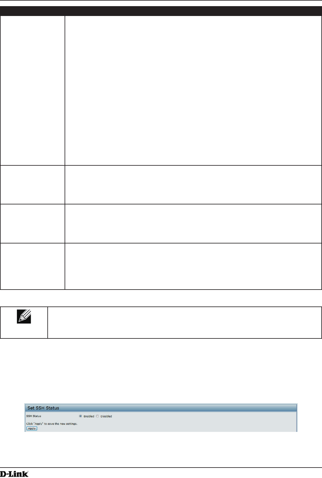
Unied Access Point Administrator’s Guide
Unied Access Point Administrator’s Guide
Page 68
May 2016
Section 5 - Conguring Access Point Services
Field Description
Hostname,
address or subnet
of Network
Management
System
Specify the IPv4 DNS hostname or subnet of the machines that can execute get and set
requests to the managed devices. The valid range is 1-256 characters.
As with community names, this provides a level of security on SNMP settings. The SNMP
agent will only accept requests from the hostname or subnet specied here.
To specify a subnet, enter one or more subnetwork address ranges in the form address/
mask_length where address is an IP address and mask_length is the number of mask bits.
Both formats address/mask and address/mask_length are supported. Individual hosts
can be provided for this, i.e. IP Address or Hostname. For example, if you enter a range of
192.168.1.0/24 this species a subnetwork with address 192.168.1.0 and a subnet mask of
255.255.255.0.
The address range is used to specify the subnet of the designated NMS. Only machines
with IP addresses in this range are permitted to execute get and set requests on the
managed device. Given the example above, the machines with addresses from 192.168.1.1
through 192.168.1.254 can execute SNMP commands on the device. (The address
identied by sufx .0 in a subnetwork range is always reserved for the subnet address, and
the address identied by .255 in the range is always reserved for the broadcast address).
As another example, if you enter a range of 10.10.1.128/25 machines with IP addresses
from 10.10.1.129 through 10.10.1.254 can execute SNMP requests on managed devices. In
this example, 10.10.1.128 is the network address and 10.10.1.255 is the broadcast address.
126 addresses would be designated.
IPv6 Hostname
or IPv6 subnet
of Network
Management
System
Specify the IPv6 DNS hostname or subnet of the machines that can execute get and set
requests to the managed devices.
Community name
for traps
Enter the global community string associated with SNMP traps. The valid range is 1-256
characters.
Traps sent from the device will provide this string as a community name.
The community name can be in any alphanumeric format. Special characters are not
permitted.
Hostname or IP
address
Enter the DNS hostname of the computer to which you want to send SNMP traps. The valid
range is 1-256 characters.
An example of a DNS hostname is: snmptraps.foo.com. Since SNMP traps are sent
randomly from the SNMP agent, it makes sense to specify where exactly the traps should
be sent. You can add up to a maximum of three DNS hostnames. Ensure you select the
Enabled check box beside the appropriate hostname.
Table 37 - SNMP Settings
Note: After you congure the SNMP settings, you must click Apply to apply the changes and
to save the settings. Changing some settings might cause the AP to stop and restart system
processes. If this happens, wireless clients will temporarily lose connectivity. We recommend that
you change AP settings when WLAN trafc is low.
Setting the SSH Status
Secure Shell (SSH) is a program that provides access to the DWL-x600AP CLI from a remote host. SSH is more
secure than Telnet for remote access because it provides strong authentication and secure communications over
insecure channels. From the SSH page, you can enable or disable SSH access to the system.
Figure 35 - Set SSH Status
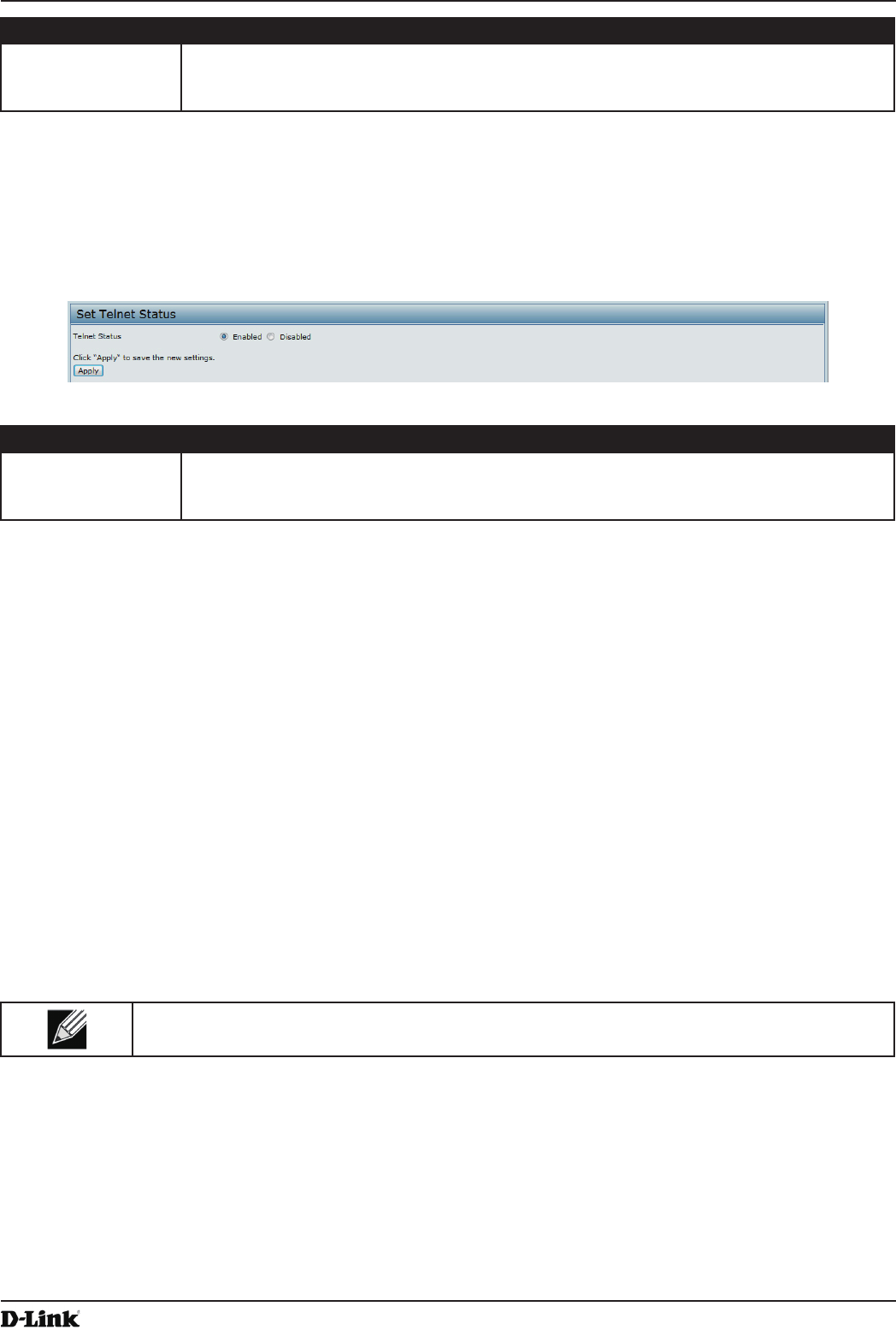
Unied Access Point Administrator’s Guide
Unied Access Point Administrator’s Guide
Page 69
May 2016
Section 5 - Conguring Access Point Services
Field Description
SSH Status Choose to either enable or disable SSH access to the AP CLI:
•) To permit remote access to the AP by using SSH, click Enabled.
•) To prevent remote access to the AP by using SSH, click Disabled.
Table 38 - SSH Settings
Setting the Telnet Status
Telnet is a program that provides access to the DWL-x600AP CLI from a remote host. From the Telnet page, you can
enable or disable Telnet access to the system.
Figure 36 - Set Telnet Status
Field Description
Telnet Status Choose to either enable or disable Telnet access to the AP CLI:
•) To permit remote access to the AP by using Telnet, click Enabled.
•) To prevent remote access to the AP by using Telnet, click Disabled.
Table 39 - Telnet Settings
Conguring Quality of Service
Quality of Service (QoS) provides you with the ability to specify parameters on multiple queues for increased
throughput and better performance of differentiated wireless trafc like Voice-over-IP (VoIP), other types of audio,
video, and streaming media, as well as traditional IP data over the UAP.
Conguring QoS on the UAP consists of setting parameters on existing queues for different types of wireless trafc,
and effectively specifying minimum and maximum wait times (through Contention Windows) for transmission. The
settings described here apply to data transmission behavior on the AP only, not to that of the client stations.
AP Enhanced Distributed Channel Access (EDCA) Parameters affect trafc owing from the AP to the client station.
Station Enhanced Distributed Channel Access (EDCA) Parameters affect trafc owing from the client station to the
A P.
The default values for the AP and station EDCA parameters are those suggested by the Wi-Fi Alliance in the WMM
specication. In normal use these values should not need to be changed. Changing these values will affect the QoS
provided.
Note: On the DWL-6600AP and DWL-8600AP, the QoS settings apply to both radios, but the trafc
for each radio is queued independently.
To set up queues for QoS, click the QoS tab under the Services heading and congure settings as described in the
table below.
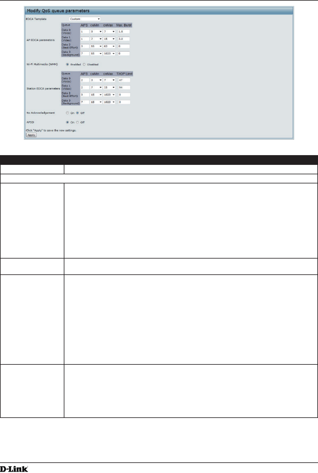
Unied Access Point Administrator’s Guide
Unied Access Point Administrator’s Guide
Page 70
May 2016
Section 5 - Conguring Access Point Services
Figure 37 - Modify QoS Queue Parameters
Field Description
EDCA Template Possible options are: Default, Optimized for Voice, and Custom.
AP EDCA Parameters
Queue Queues are dened for different types of data transmitted from AP-to-station:
•) Data 0 (Voice) — High priority queue, minimum delay. Time-sensitive data such as
VoIP and streaming media are automatically sent to this queue.
•) Data 1(Video) — High priority queue, minimum delay. Time-sensitive video data is
automatically sent to this queue.
•) Data 2 (Best Effort) — Medium priority queue, medium throughput and delay. Most
traditional IP data is sent to this queue.
•) Data 3 (Background) — Lowest priority queue, high throughput. Bulk data that
requires maximum throughput and is not time-sensitive is sent to this queue (FTP
data, for example).
AIFS (Inter-Frame
Space)
The Arbitration Inter-Frame Spacing (AIFS) species a wait time for data frames. The wait
time is measured in slots. Valid values for AIFS are 1 through 255.
cwMin (Minimum
Contention Window)
This parameter is input to the algorithm that determines the initial random back off wait time
(window) for retry of a transmission.
The value specied for Minimum Contention Window is the upper limit (in milliseconds) of a
range from which the initial random back off wait time is determined.
The rst random number generated will be a number between 0 and the number specied
here.
If the rst random back off wait time expires before the data frame is sent, a retry counter
is incremented and the random back off value (window) is doubled. Doubling will continue
until the size of the random back off value reaches the number dened in the Maximum
Contention Window.
Valid values for cwMin are 1, 3, 7, 15, 31, 63, 127, 255, 511, or 1024. The value for cwMin
must be lower than the value for cwMax.
cwMax (Maximum
Contention Window)
The value specied for the Maximum Contention Window is the upper limit (in milliseconds)
for the doubling of the random back off value. This doubling continues until either the data
frame is sent or the Maximum Contention Window size is reached.
Once the Maximum Contention Window size is reached, retries will continue until a
maximum number of retries allowed is reached.
Valid values for cwMax are 1, 3, 7, 15, 31, 63, 127, 255, 511, or 1024. The value for cwMax
must be higher than the value for cwMin.