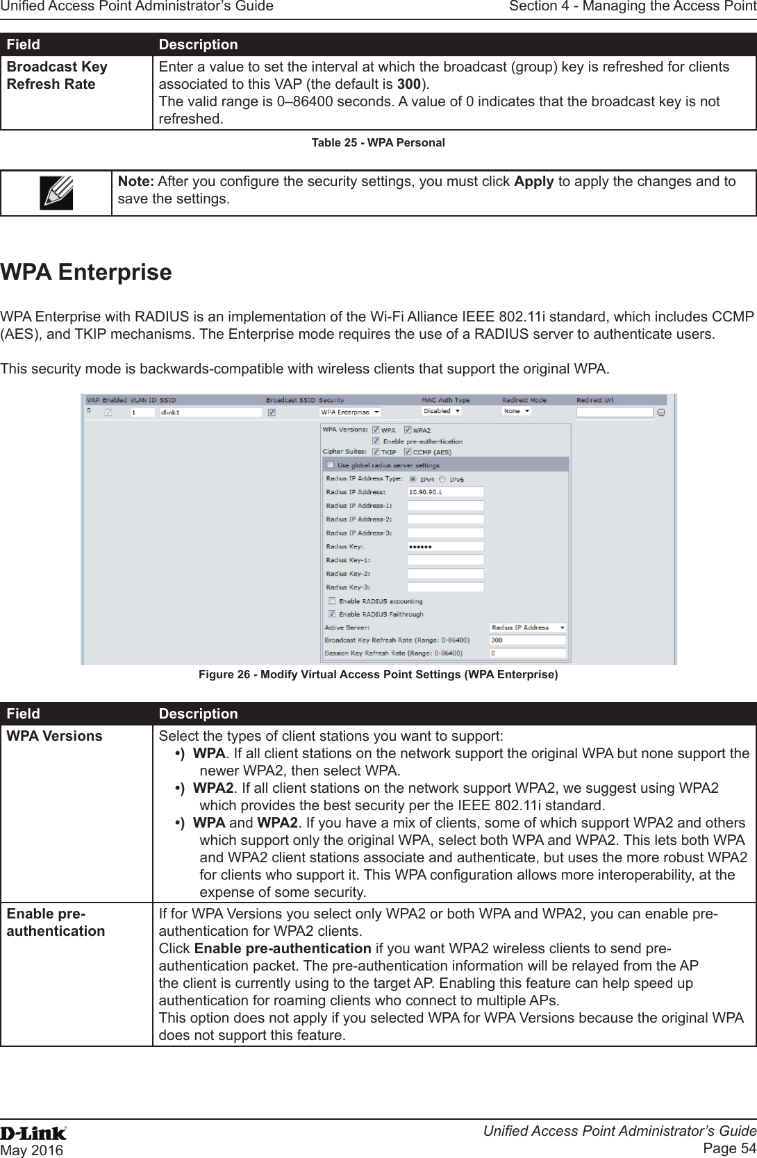
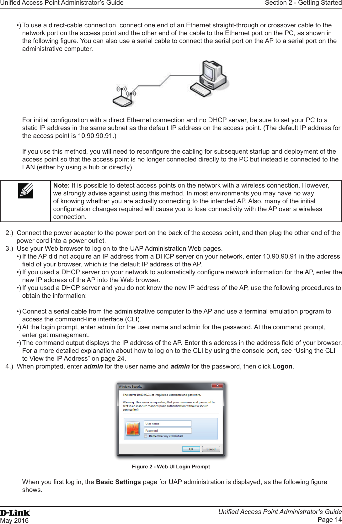
D Link WL3610APA1 Unified AC Selectable Dual-band PoE Access Point User Manual 0420
D Link Corporation Unified AC Selectable Dual-band PoE Access Point 0420
D Link >
Contents
- 1. Users Manual_1
- 2. Users Manual_2
- 3. User Manual
Users Manual_1
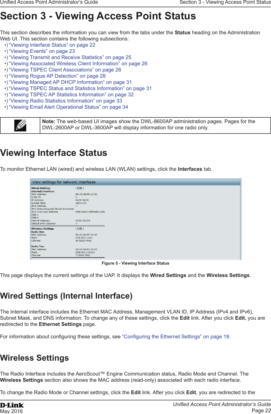
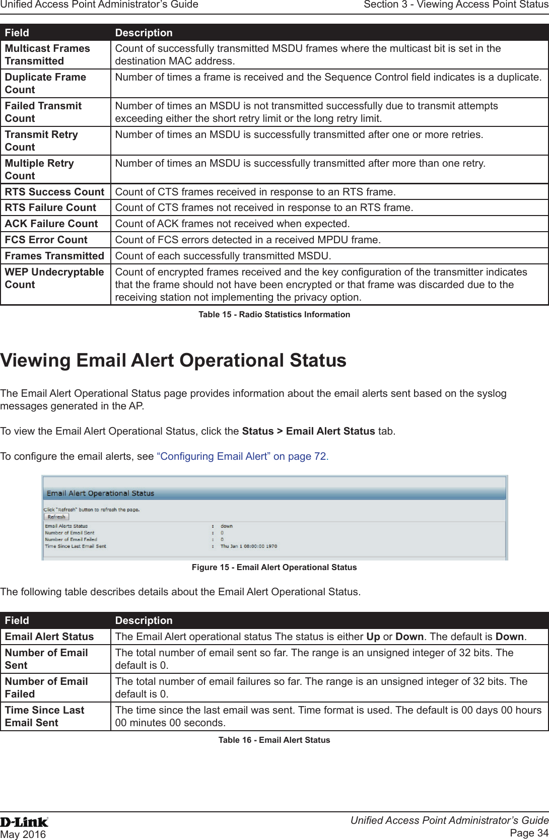
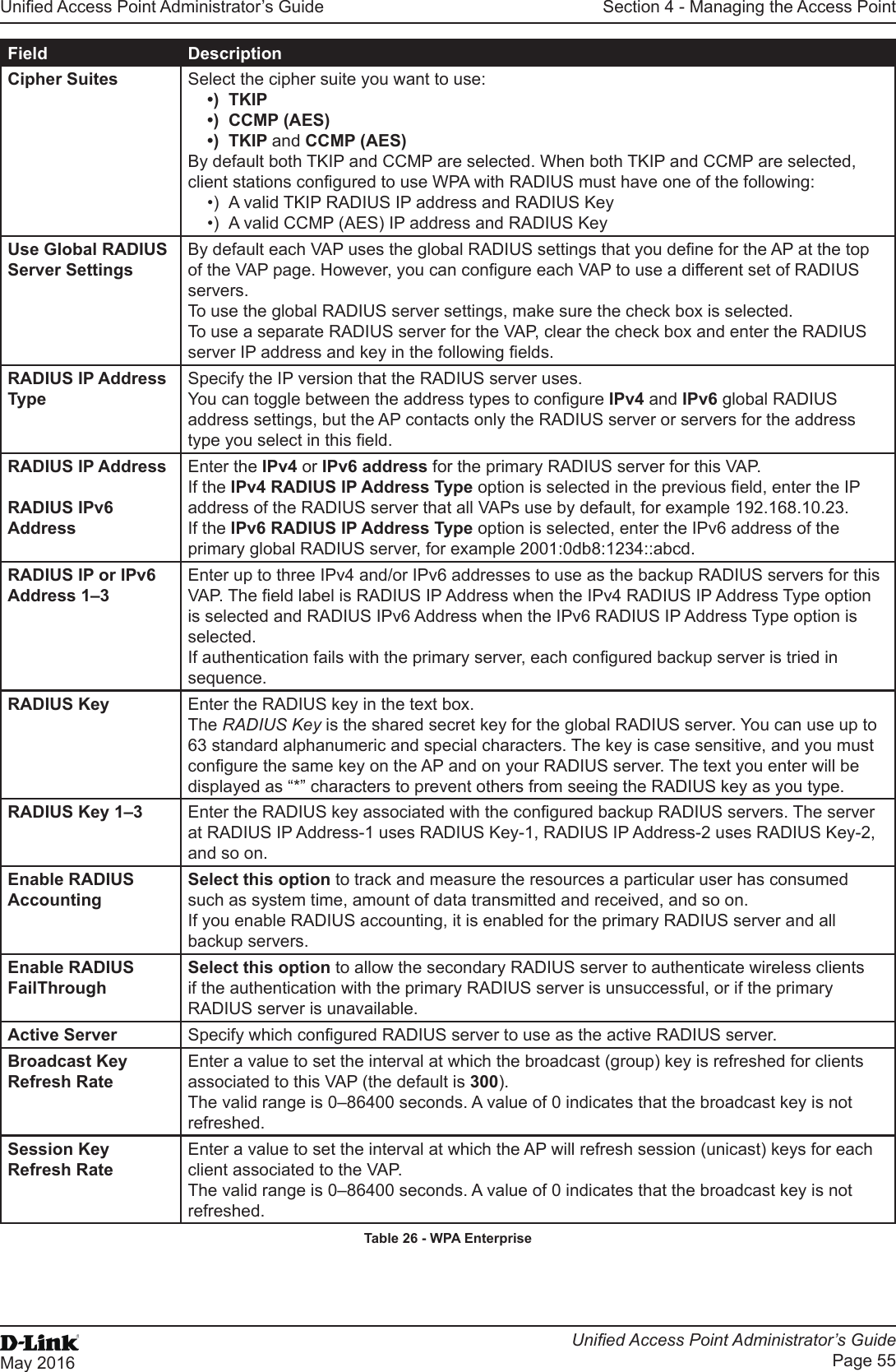
![Unied Access Point Administrator’s GuideUnied Access Point Administrator’s GuidePage 9May 2016Section 1 - About This DocumentSection 1 - About This DocumentThis guide describes setup, conguration, administration and maintenance for the D-Link DWL-x600AP Unied Access Point (UAP) on a wireless network.Document OrganizationThe Unied Access Point Administrator’s Guide contains the following sections:•) “Section 1 - About This Document” on page 9•) “Section 2 - Getting Started” on page 11•) “Section 3 - Viewing Access Point Status” on page 22•) “Section 4 - Managing the Access Point” on page 35•) “Section 5 - Conguring Access Point Services” on page 65•) “Section 6 - Conguring SNMPv3” on page 75•) “Section 7 - Maintaining the Access Point” on page 79•) “Section 8 - Conguring Client Quality of Service (QoS)” on page 88•) “Section 9 - Clustering Multiple APs” on page 104•) “Appendix A - Default AP Settings” on page 113•) “Appendix B - Conguration Examples” on page 115Additional DocumentationThe following documentation provides additional information about Unied Access Point software:•) The Unied Access Point CLI Command Reference describes the commands available from the command-line interface (CLI) for managing, monitoring, and conguring the switch.•) The User Manual for the D-Link Unied Wired and Wireless System provides information about setting up and managing the Unied Wireless Switch (UWS), including information about how to use the switch to manage multiple UAPs. •) Release notes for the D-Link Unied Wired and Wireless System detail the platform-specic functionality of the software packages, including issues and workarounds.Document ConventionsThis section describes the conventions this document uses.Note: A note provides more information about a feature or technology and cross-references to related topics.Caution! A caution provides information about critical aspects of AP conguration, combinations of settings, events, or procedures that can adversely affect network connectivity, security, and so on.The following table describes the typographical conventions used in this guide.Symbol Example DescriptionBold Click Apply to save your settings. Menu titles, page names, and button names.Blue Text See “Document Conventions” on page 9Hyperlink text.Courier Font WLAN-AP# show network Screen text, le names, commands, user-typed command-line entries.Courier Font ItalicsValue Command parameter, which might be a variable or xed value.Square Brackets [ ] [Value] Indicates an optional xed parameter.](https://usermanual.wiki/D-Link/WL3610APA1.Users-Manual-1/User-Guide-3371498-Page-9.png)
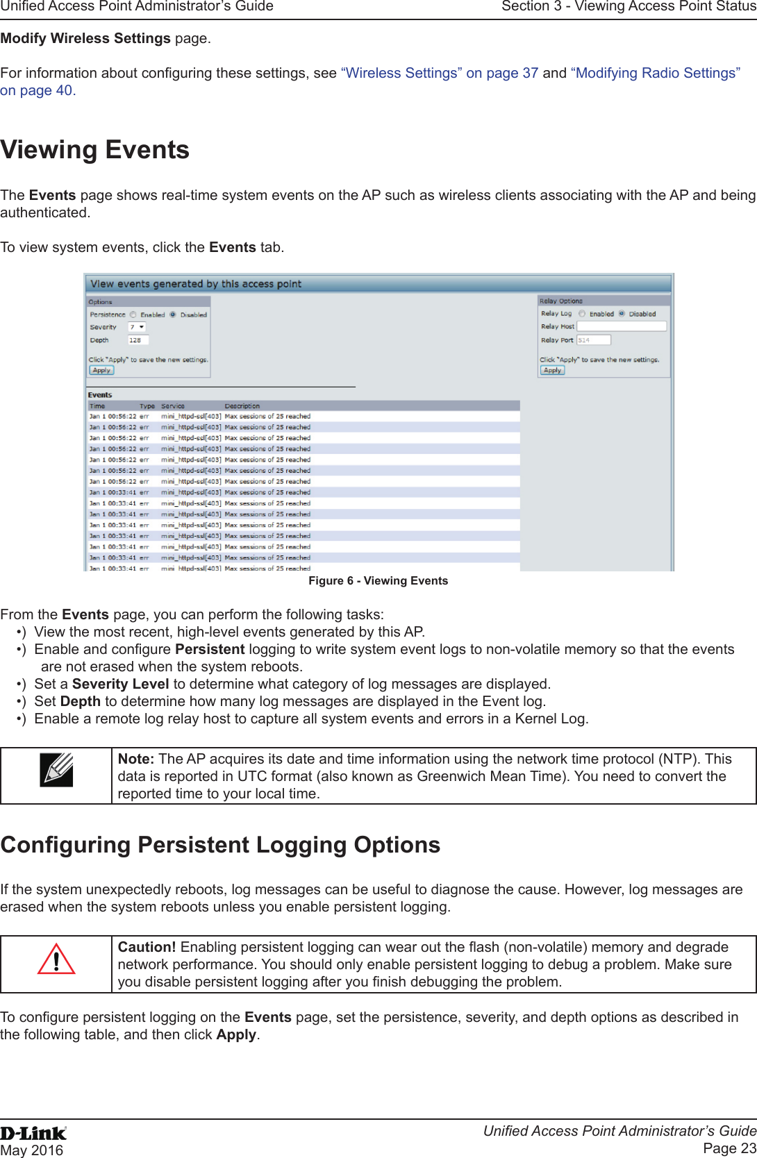
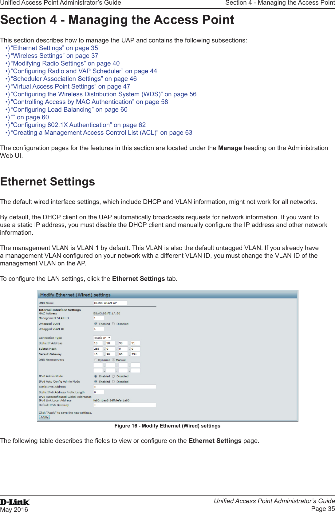
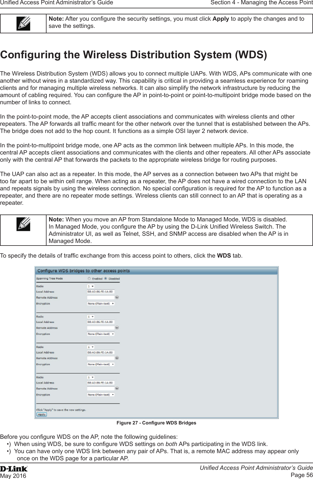
![Unied Access Point Administrator’s GuideUnied Access Point Administrator’s GuidePage 10May 2016Section 1 - About This DocumentSymbol Example DescriptionCurly Braces {} {Choice1 | Choice2} Indicates that you must select a parameter from the list of choices.Vertical Bars | Choice1 | Choice2 Separates the mutually exclusive choices.Braces within square brackets [{}][{Choice1 | Choice2}] Indicate a choice within an optional element.Table 1 - Typographical ConventionsOnline Help, Supported Browsers, and LimitationsOnline help for the UAP Administration Web pages provides information about all elds and features available from the user interface (UI). The information in the online help is a subset of the information available in the Unied Access Point Administrator’s Guide.Online help information corresponds to each page on the UAP Administration UI. For information about the settings on the current page, click the Help link on the upper right side of a page. The following gure shows an example of the online help available from the links on the user interface.Figure 1 - Administrator UI Online Help](https://usermanual.wiki/D-Link/WL3610APA1.Users-Manual-1/User-Guide-3371498-Page-10.png)
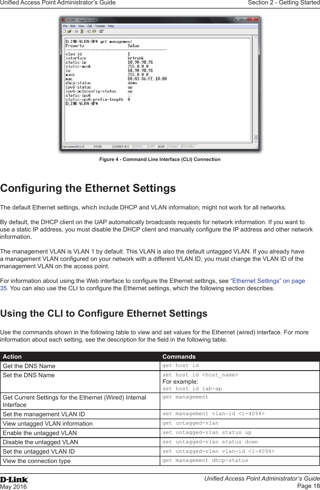
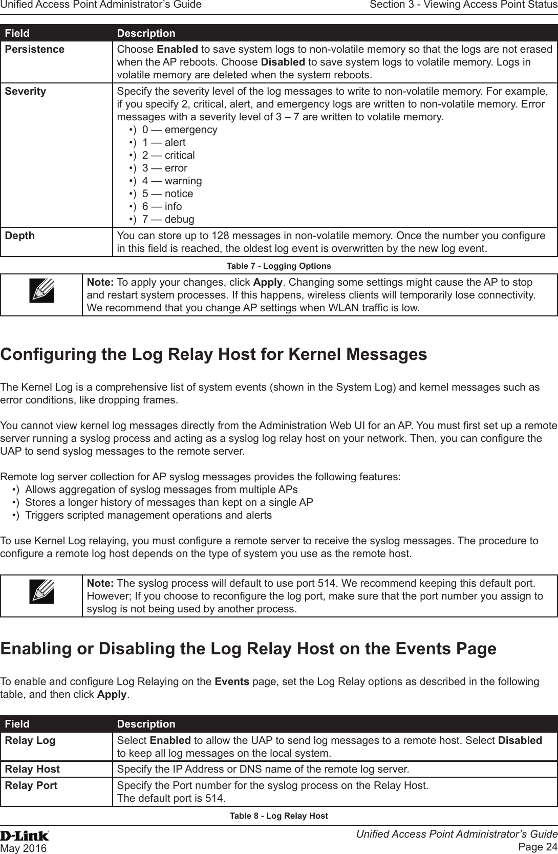
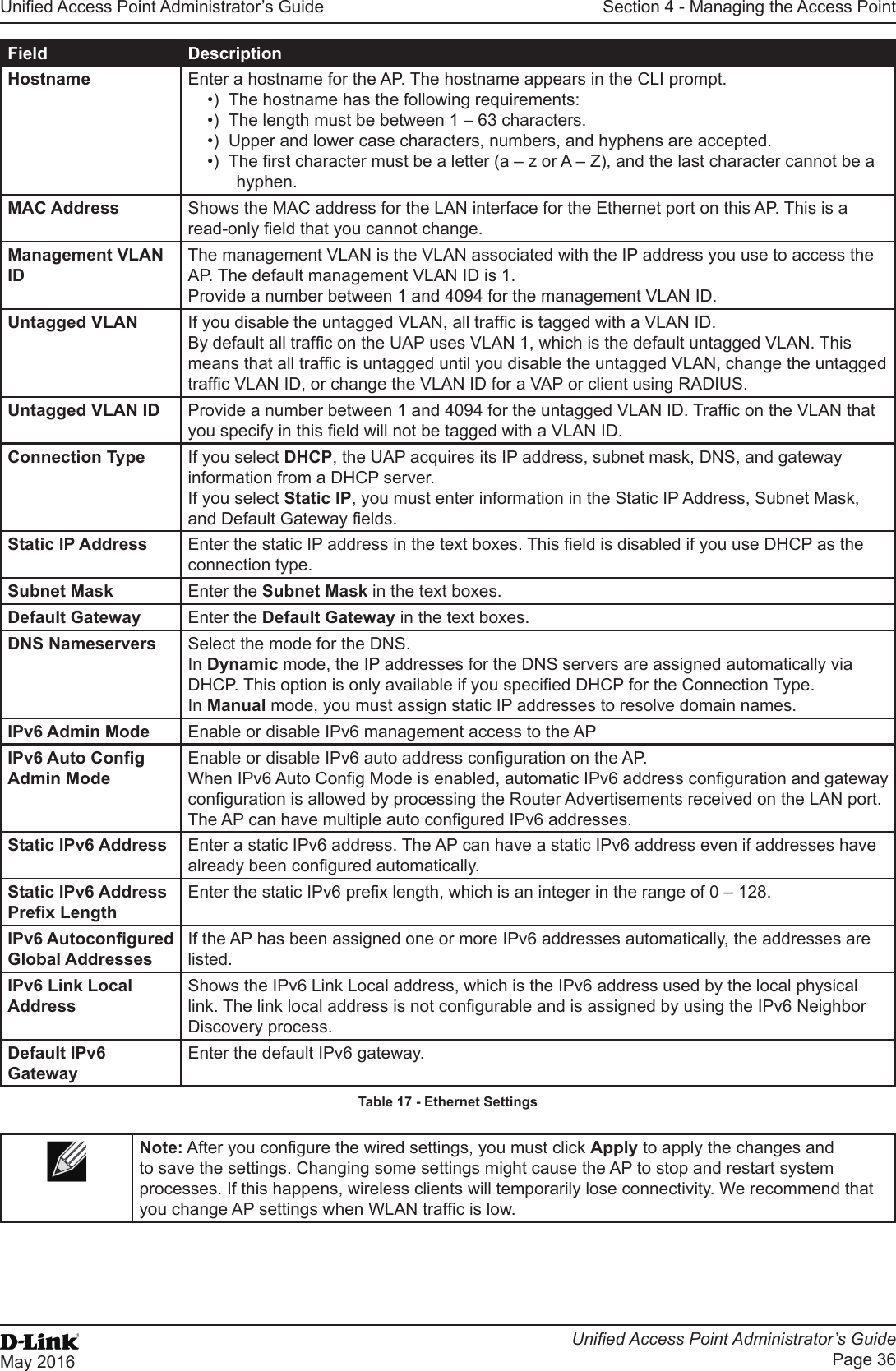
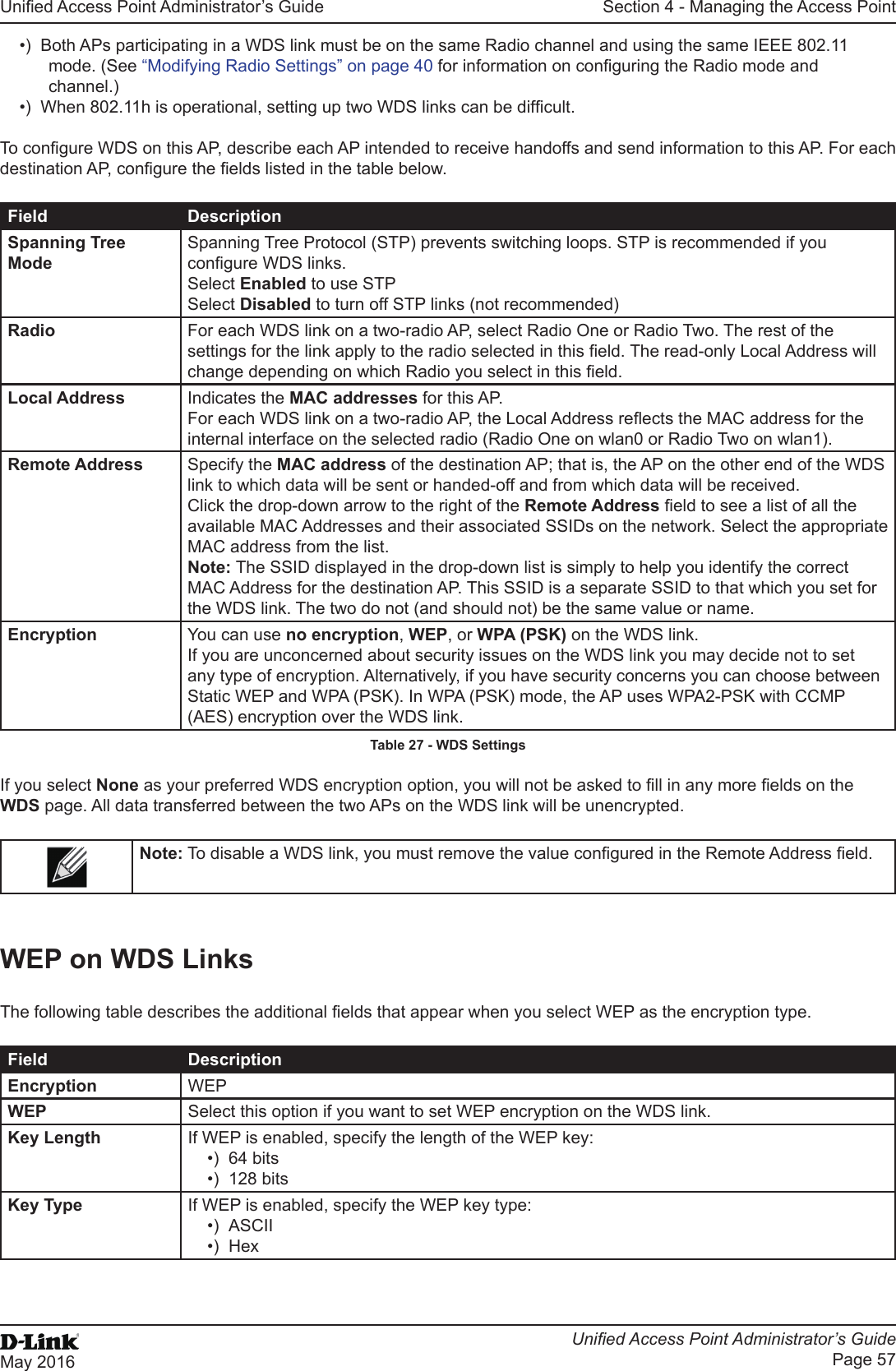
![Unied Access Point Administrator’s GuideUnied Access Point Administrator’s GuidePage 17May 2016Section 2 - Getting StartedField DescriptionSystem Contact Enter the name, e-mail address, or phone number of the person to contact regarding issues related to the AP.System Location Enter the physical location of the AP, for example Conference Room A.Table 4 - Basic Settings PageConnecting to the AP Web Interface by Using the IPv6 AddressTo connect to the AP by using the IPv6 global address or IPv6 link local address, you must enter the AP address into your browser in a special format.Note: The following instructions and examples work with Microsoft Internet Explorer 7 (IE7) and might not work with other browsers.To connect to an IPv6 global address, add square brackets around the IPv6 address. For example, if the AP global IPv6 address is 2520::230:abff:fe00:2420, type the following address into the IE7 address eld: http://[2520::230:abff:fe00:2420].To connect to the iPv6 link local address, replace the colons (:) with hyphens (-), add the interface number preceded with an “s,” then add “.ipv6-literal.net.” For example, if the AP link local address is fe80::230:abff:fe00:2420, and the Windows interface is dened as “%6,” type the following address into the IE7 address eld: http://fe80--230-abff-fe00-2420s6.ipv6-literal.net.Using the CLI to View the IP AddressThe DHCP client on the UAP is enabled by default. If you connect the UAP to a network with a DHCP server, the AP automatically acquires an IP address. To manage the UAP by using the Administrator UI, you must enter the IP address of the access point into a Web browser. If a DHCP server on your network assigns an IP address to the UAP, and you do not know the IP address, use the following steps to view the IP address of the UAP:1.) Using a null-modem cable, connect a VT100/ANSI terminal or a workstation to the console (serial) port.If you attached a PC, Apple, or UNIX workstation, start a terminal-emulation program, such as HyperTerminal or TeraTerm.2.) Congure the terminal-emulation program to use the following settings:•) Baud rate: 115200 bps•) Data bits: 8•) Parity: none•) Stop bit: 1•) Flow control: none3.) Press the return key, and a login prompt should appear.The login name is admin. The default password is admin. After a successful login, the screen shows the (Access Point Name)# prompt. 4.) At the login prompt, enter get management.Information similar to the following prints to the screen.](https://usermanual.wiki/D-Link/WL3610APA1.Users-Manual-1/User-Guide-3371498-Page-17.png)