D Link WL3610APA1 Unified AC Selectable Dual-band PoE Access Point User Manual 0420
D Link Corporation Unified AC Selectable Dual-band PoE Access Point 0420
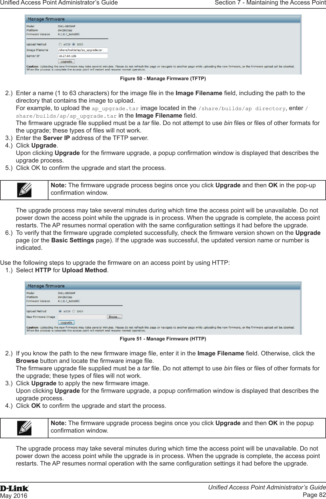
D Link >
Contents
- 1. Users Manual_1
- 2. Users Manual_2
- 3. User Manual
Users Manual_2
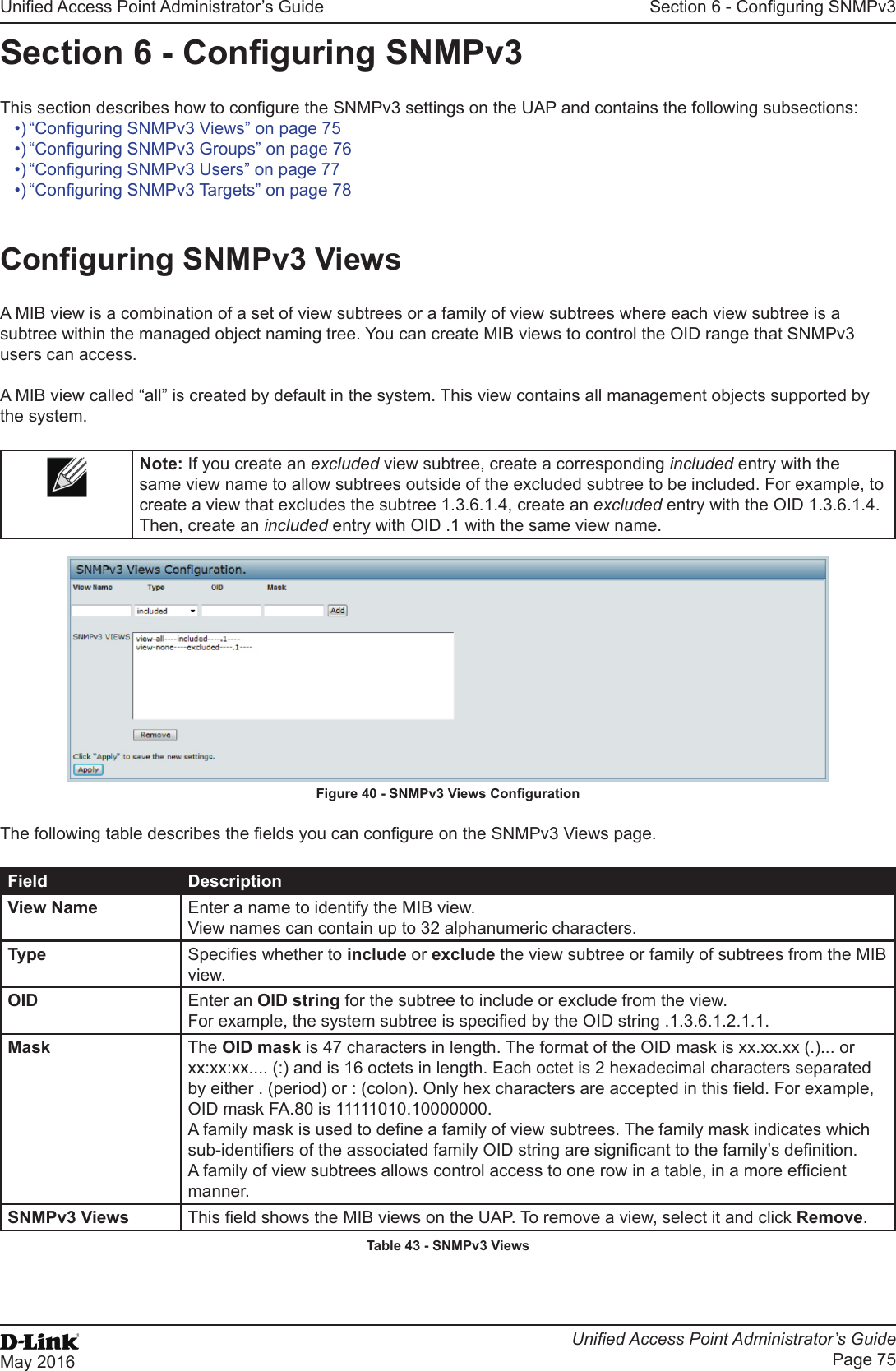
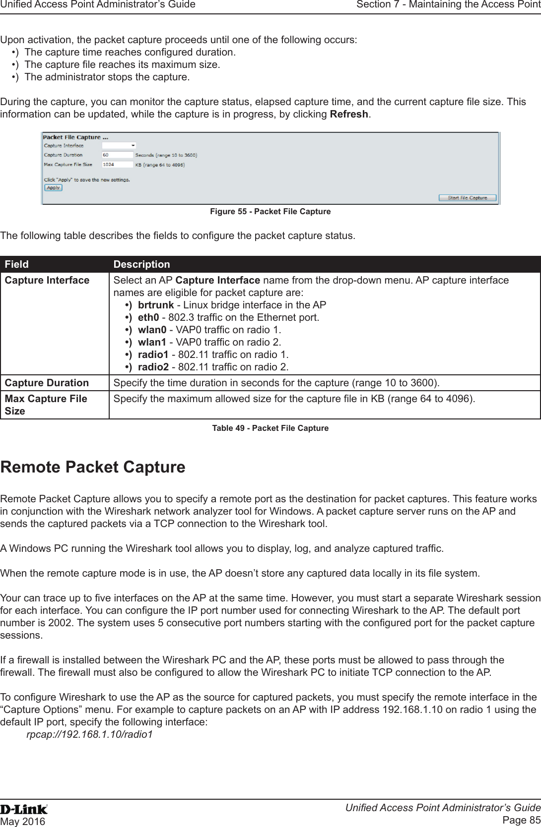
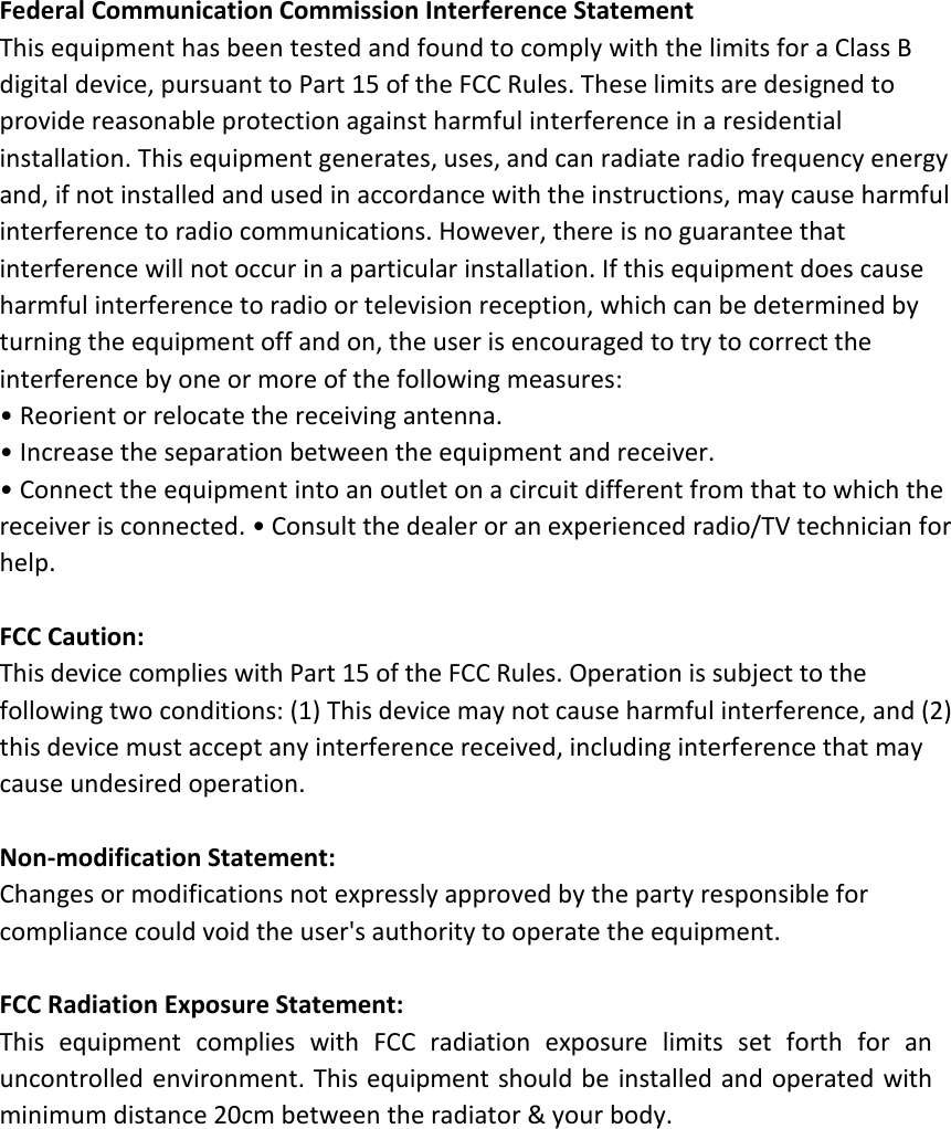
![Unied Access Point Administrator’s GuideUnied Access Point Administrator’s GuidePage 73May 2016Section 5 - Conguring Access Point ServicesField DescriptionNon Urgent Severity Congures the severity level for log messages that are considered to be non-urgent. Messages in this category are collected and sent in a digest form at the time interval specied by the Log Duration eld. The security level you select and all levels up to, but not including the lowest Urgent level are considered non-urgent. Messages below the security level you specify are not sent via email. See the Urgent Message eld description for information about the security levels.Email Alert Mail Server CongurationMail Server Address Specify the IP address or hostname of the SMTP server on the network.Mail Server Security Specify whether to use SMTP over SSL (TLSv1) or no security (Open) for authentication with the mail server. The default is Open.Mail Server Port Congures the TCP port number for SMTP. The range is a valid port number from 0 to 65535. The default is 25, which is the standard port for SMTP.Username Specify the username to use when authentication with the mail server is required. The username is a 64-byte character string with all printable characters. The default is admin.Password Specify the password associated with the username congured in the previous eld.Email Alert Message CongurationTo Address 1 Congure the rst email address to which alert messages are sent. The address must be a valid email address. By default, no address is congured.To Address 2 Optionally, congure the second email address to which alert messages are sent. The address must be a valid email address. By default, no address is congured.To Address 3 Optionally, congure the third email address to which alert messages are sent. The address must be a valid email address. By default, no address is congured.Email Subject Specify the text to be displayed in the subject of the email alert message. The subject can contain up to 255 alphanumeric characters. The default is Log message from AP.Table 41 - Email Alert CongurationNote: After you congure the Email Alert settings, click Apply to apply the changes and to save the settings. To validate the congured email server credentials, click Test Mail. You can send a test email once the email server details are congured.The following text shows an example of an email alert sent from the AP to the network administrator:From: AP-192.168.2.10@mailserver.com Sent: Wednesday, July 08, 2011 11:16 AMTo: administrator@mailserver.comSubject: log message from APTIME Priority Process Id MessageJul 8 03:48:25 info login[1457] root login on ‘ttyp0’Jul 8 03:48:26 info mini_http-ssl[1175] Max concurrent connections of 20 reachedEnabling the Time Settings (NTP)Use the Time Settings page to specify the Network Time Protocol (NTP) server to use to provide time and date information to the AP or to congure the time and date information manually.NTP is an Internet standard protocol that synchronizes computer clock times on your network. NTP servers transmit Coordinated Universal Time (UTC, also known as Greenwich Mean Time) to their client systems. NTP sends periodic time requests to servers, using the returned time stamp to adjust its clock. The timestamp is used to indicate the date and time of each event in log messages.See http://www.ntp.org for more information about NTP.](https://usermanual.wiki/D-Link/WL3610APA1.Users-Manual-2/User-Guide-3371499-Page-3.png)