DASAN Network Solutions H640GW G-PON ONT User Manual H640GW N A QIG EN 130509 V3 ai
DASAN Network Solutions, Inc. G-PON ONT H640GW N A QIG EN 130509 V3 ai
User Manual
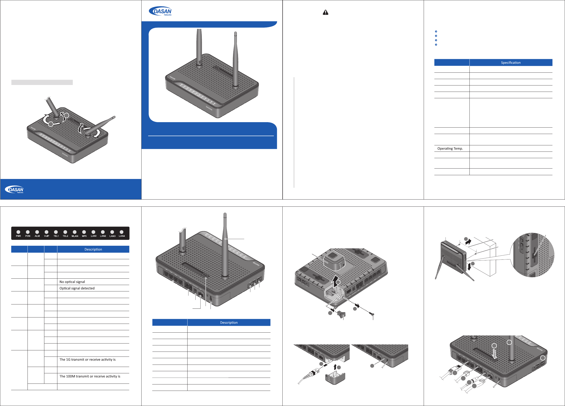
3. Installaon
ⴘLoosen the screw from the opc cover.
ⴙPull the opc cover out from the body.
ⴚRemove the cap from GPON port.
3.1 Connecng to Network (through GPON port)
GPON Opcal Network Terminal (ONT) with VoIP & Wi-Fi
)(8
2*(2VJDL(VJEF
V3
1. Cauon
Informaon furnished by DASAN Networks USA, Inc. is believed to be accurate and reliable. However, no responsibility
is assumed by DASAN Networks for its use, nor for any infringements of patents or other rights of third pares which
may result from its use. No license is granted by implicaon or otherwise under any patent or patent rights of DASAN
Networks. DASAN Networks reserves the rights to change specificaons at any me without noce.
Copyright © 2013 by DASAN Networks USA, Inc. All rights reserved.
DASAN Networks USA, Inc. www.dasannetworksus.com
2. Introducon
2.1 Package Contents
H640GW
RJ45 UTP Cable
Power Adapter
QIG (Quick Guide)
2.2 Specificaon
Item
System Memory 128MB DDR3
Flash Memory 128MB Nand Flash
Uplink Interface 1 GPON port (SC/APC)
Service Interface 4 10/100/1000Base-T ports (RJ45)
VoIP Interface 2 FXS ports (RJ11)
Wireless
IEEE 802.11b/g/n compliant
Bandwidth: 2.4GHz
Two Transmit and Two Receive path (2T2R)
Max. data rate: 54Mbps in 802.11g
300Mbps in 802.11n
Security: WEP, WPA-PSK (TKIP) & WPA2-PSK (AES)
LED
PWR, PON, ALM, VoIP, TEL1~2, WLAN, WPS*, LAN1~4
Power Power port: AC/DC adapter, 12VDC/1.5A
BBU port: For Baery Backup Unit
32 to 104°F (0 to 40°C)
Humidity 5 to 90% (non-condensing)
Dimensions
(W x D x H)
7.48 x 5.90 x 2.44 in (190 × 150 × 62 mm)
(including folded antenna)
Buon On/Off power, WLAN, WPS*, RESET
2.4 Rear View2.3 Front View (LEDs)
Label Light Status
PWR Green On
Off The system is turned off.
The system is turned on.
PON Green On Register OK. The GPON port link is up.
Off Not registered. The GPON port link is down.
ALM Red On
Off
TEL
1~2 Green On Off-hook
Off On-hook
VoIP Green On Register OK
Off Not registered
LAN
1~4
(LNK/
ACT)
Green
On The 1G port link is up.
Blink present on the service port.
Orange
On The 100M port link is up.
Blink present on the service port.
Off Link down
WPS Green
Blink In progress
On Success (for 5 seconds)
Off Disabled or process finished
WLAN Green On Wireless funcon enabled
Off Wireless funcon disabled
Item
ྙ OPTICAL Connect the network.
ྚ LAN1~4 Connect PC or LAN.
ྛ TEL1~2 Connect telephone.
ྜ POWER Connect power adapter.
ྜྷ ON/OFF Turn on/off the unit.
ྞ RESET Reboot the unit.
ྟ WPS Enable WPS process.
ྠ WLAN Enable wireless funcon.
ྡ Antenna Transmit and receive wireless packets.
ྡྷ BBU Connect Baery Backup Unit.
* Wi-Fi Protected Setup, a standard that aempts to automate secure wireless network
set up and connecon
ⴘPlug the Ethernet cable from LAN port to PC.
ⴙPlug the phone cable from TEL port to telephone.
ⴚConnect the power adapter from power port to a live AC outlet.
If necessay, connect a baery backup unit to BBU port instead.
ⴛTurn on the unit by pushing the power switch.
ⴜPush WLAN buon to enable WLAN.
ⴝAdjust antenna direcon for beer wireless communicaon.
For informaon of how to adjust the antenna, see TIP on the last page.
3.3 Connecng Ethernet/VoIP/Power and Enabling WLAN
4. Inial Web Access
You can access H640GW through a web browser by using the inial
LAN IP at first. The detail procedure is as follows:
ⴘ Connect LAN1 port of H640GW to your PC using Ethernet cable.
ⴙ Configure an IP address of your PC to 192.168.1.1~254 (except
192.168.1.100).
ⴚ Open a web browser, and enter hp://192.168.1.100:8080 in a
URL field.
ⴛ Type “user/user” in user name/password field, and log into the
system. Inial page is displayed.
5000 Research Court, Suite 700, Suwanee, GA 30024 www.dasannetworksus.com
DASAN Networks USA, Inc.
Θ
Ι
Κ
ΛΗ
ΜΝΞ
Ο
Π
ⴛPlug in the opc cable (SC/APC-connectorized) to connect the ONT
to the network (OLT).
ⴜAach the opc cover to the unit.
ⴝTighten the screw on the opc cover.
If necessary, you may have your ONT mounted on a wall using mounng
groove and proper screws or nails.
3.2 Mounng on a Wall
Opc Cover
GPON Port Cap
Screw
TIP for Beer Wireless Communicaon
You can make antennas oblique outside or inside the body by lng () and rotang () them
for beer wireless communicaon as like the figure below.
Groove
Screw
5.43
in (138
mm)
- This unit is indoor use and all the communicaon wirings are limited to inside of the building.
- Never look directly at the fiber TX port and fiber cable ends when they are powered on.
- DO NOT use near water.
- DO NOT place near high temperature source.
- DO NOT disassemble the unit.
- DO NOT operate the unit in a locaon where the maximum ambient temperature exceeds 104°F.
- Open opcal connecons must use a protecve cap under all circumstances to protect against
physical damage and dirt.
- Avoid impact stresses when handling connectors. Physical damage to the faces of opcal
connecons impairs transmission quality (higher aenuaon).
- Avoid a bend radius in excess of 1.18 in for fiber opc links.
- Check the available voltage supply.
- Only connect approved accessories.
- It may only be repaired by authorized service personnel.
FCC Cerficaon Requirements
● Cauon
Any changed or modificaons not expressly approved by the party responsible for
compliance could void the user`s authority to operate this equipment.
● FCC RF exposure requirements
The antenna used with this module must be installed to provide a separaon distance of
at least 20cm from all persons, and must not transmit simultaneously with any other
antenna or transmier except in accordance with FCC mul-transmier product
procedures.
● User Informaon
This device complies with Part 15 of the FCC`s Rule. Operaon is subject to the following
to condions;
1. This device may not cause harmful interference, and
2. This device must accept any interference received, including interference that may
cause undesirable operaon.
This equipment has been tested and found to comply with the limits for a Class B digital
device, pursuant to part 15 of the FCC Rules. These limits are designed to provide
reasonable protecon against harmful interference in a residenal installaon. This
equipment generates, uses and can radiate radio frequency energy and, if not installed
and used in accordance with the instrucons, may cause harmful interference to radio
communicaons. However, there is no guarantee that interference will not occur in a
parcular installaon. If this equipment does cause harmful interference to radio or
television recepon, which can be determined by turning the equipment off and on, the
user is encouraged to try to correct the interference by one or more of the following
measures:
- Reorient or relocate the receiving antenna.
- Increase the separaon between the equipment and receiver.
- Connect the equipment into an outlet on a circuit different from that to which the
receiver is connected.
- Consult the dealer or an experienced radio/TV technician for help.