DASAN Zhone Solutions 6768 XDSL 4 Port WiFi 802.11ac Gateway User Manual 66xx 67xx UG 01232016
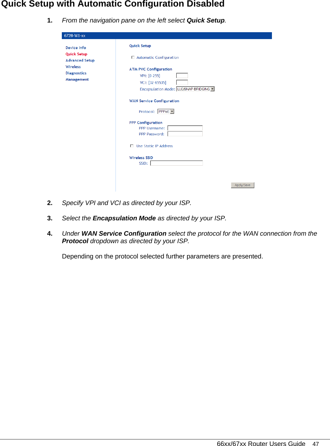
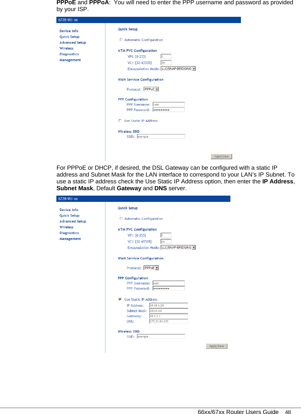
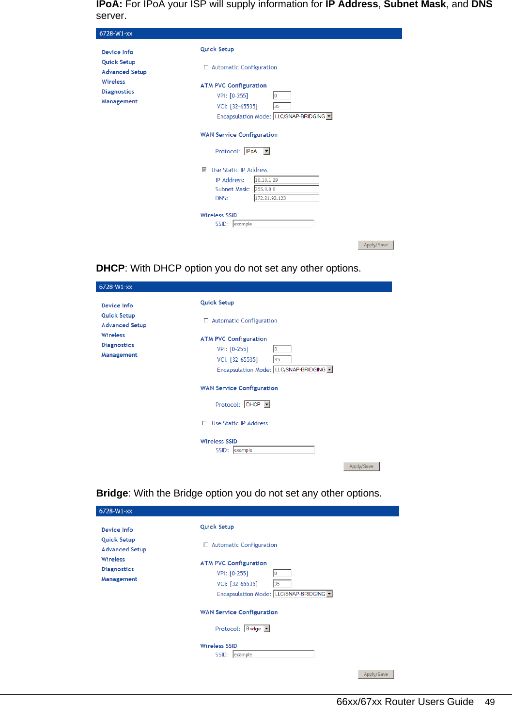
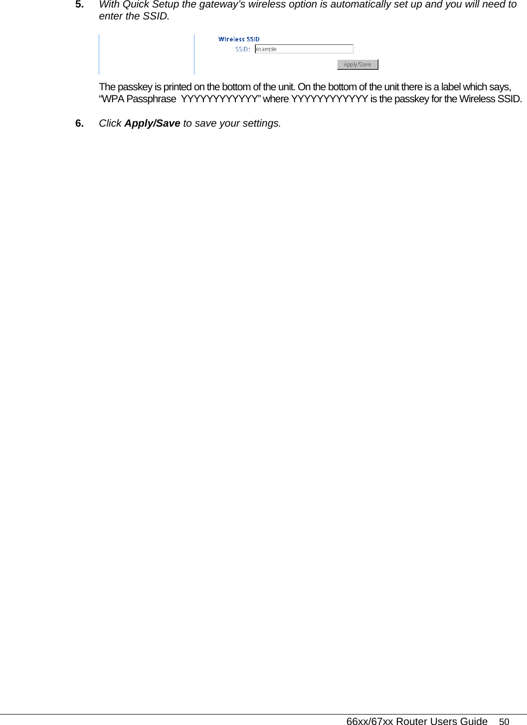
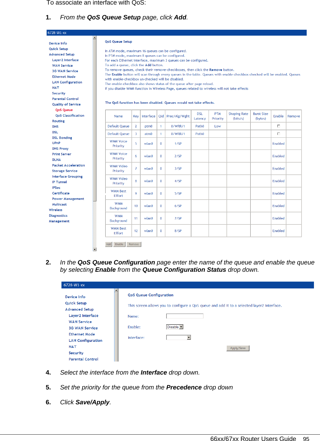
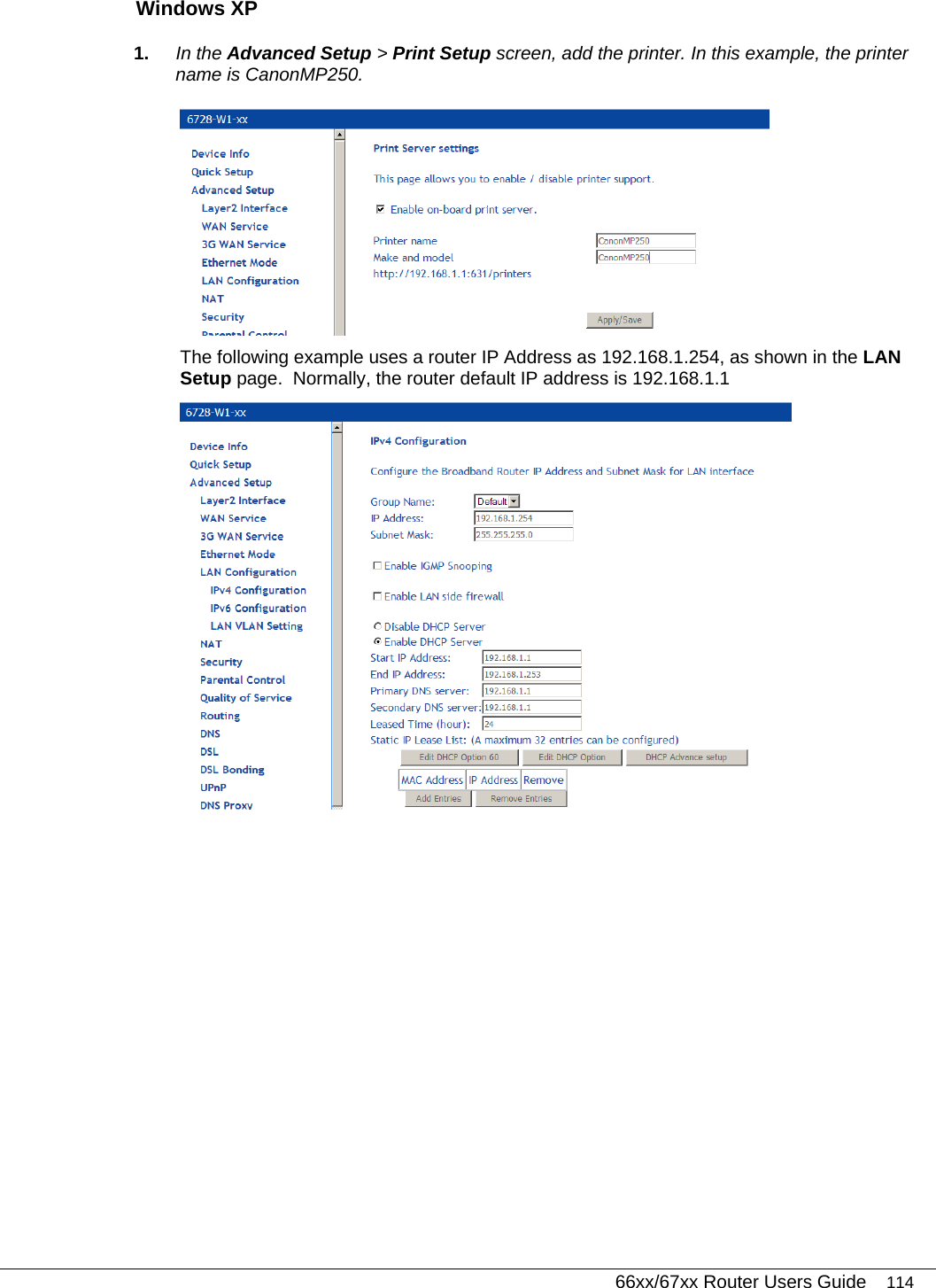
DASAN Zhone Solutions, Inc. XDSL 4 Port WiFi 802.11ac Gateway 66xx 67xx UG 01232016
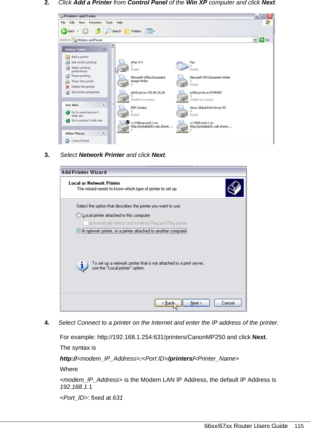
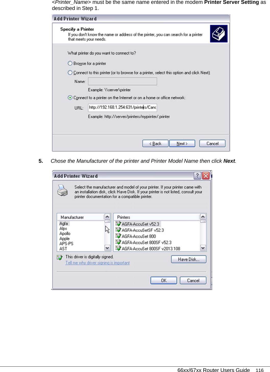
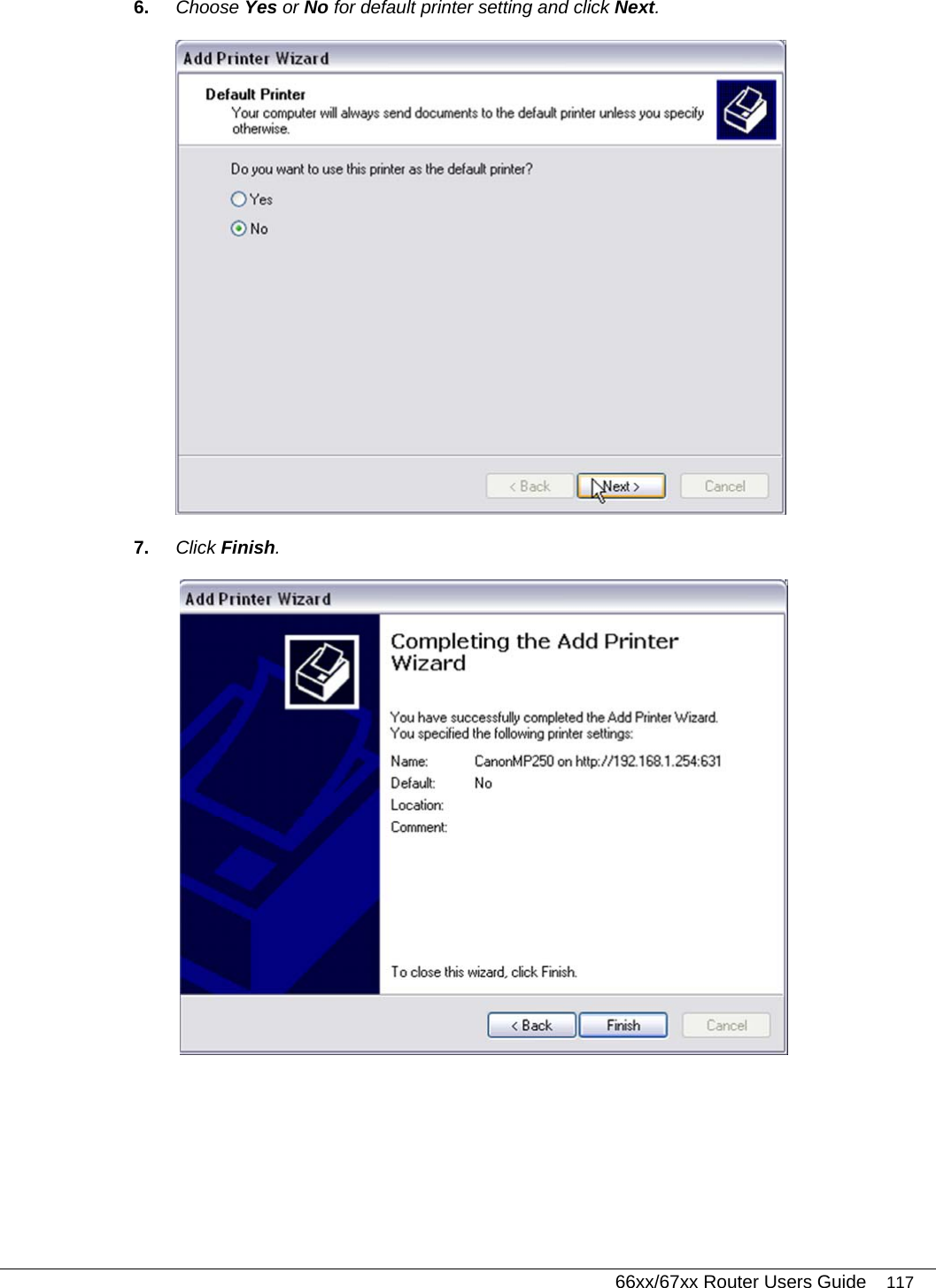
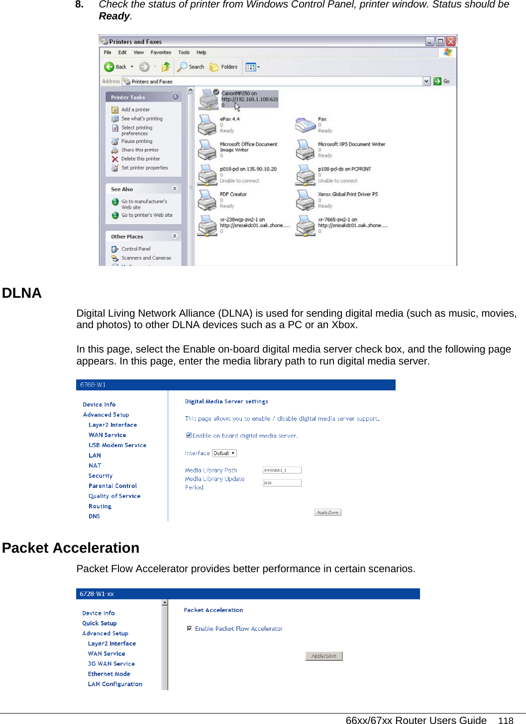
UserManual.wiki
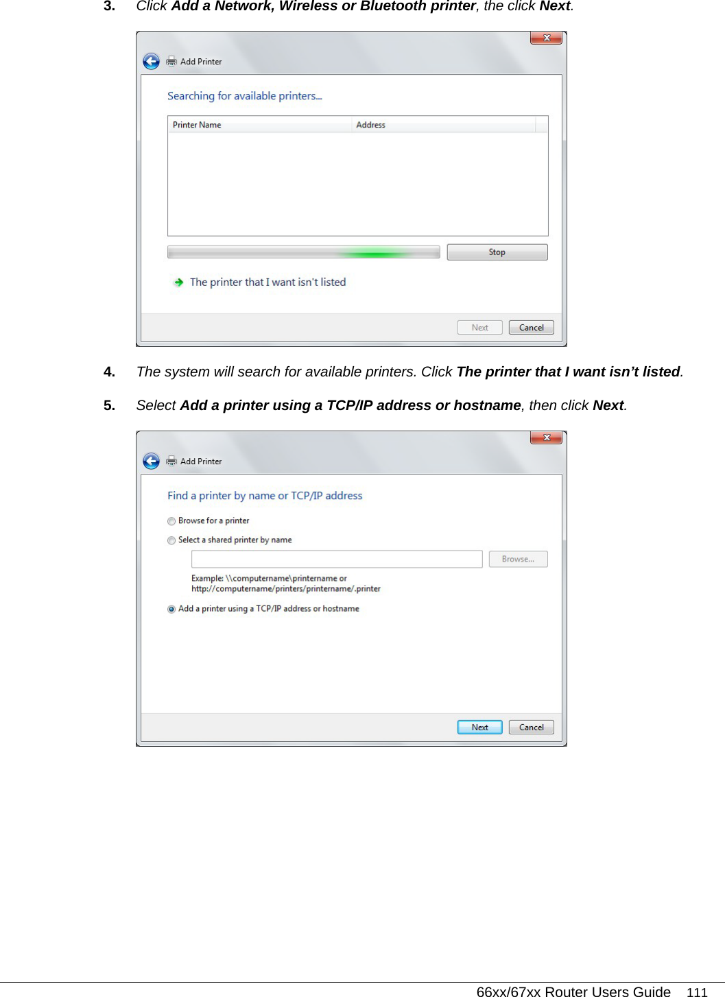
>
DASAN Zhone Solutions
>
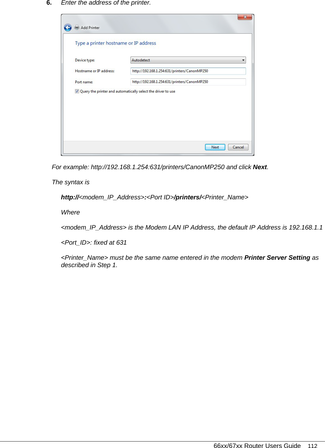
6768 User Manual
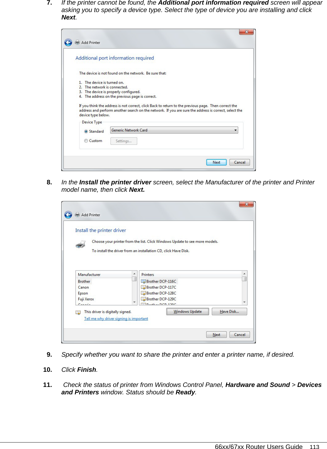
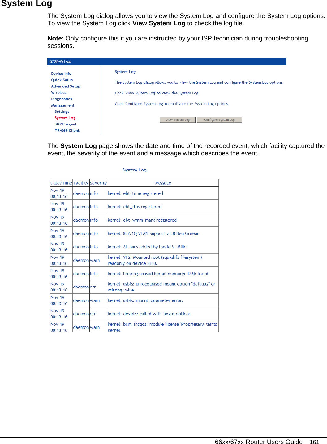
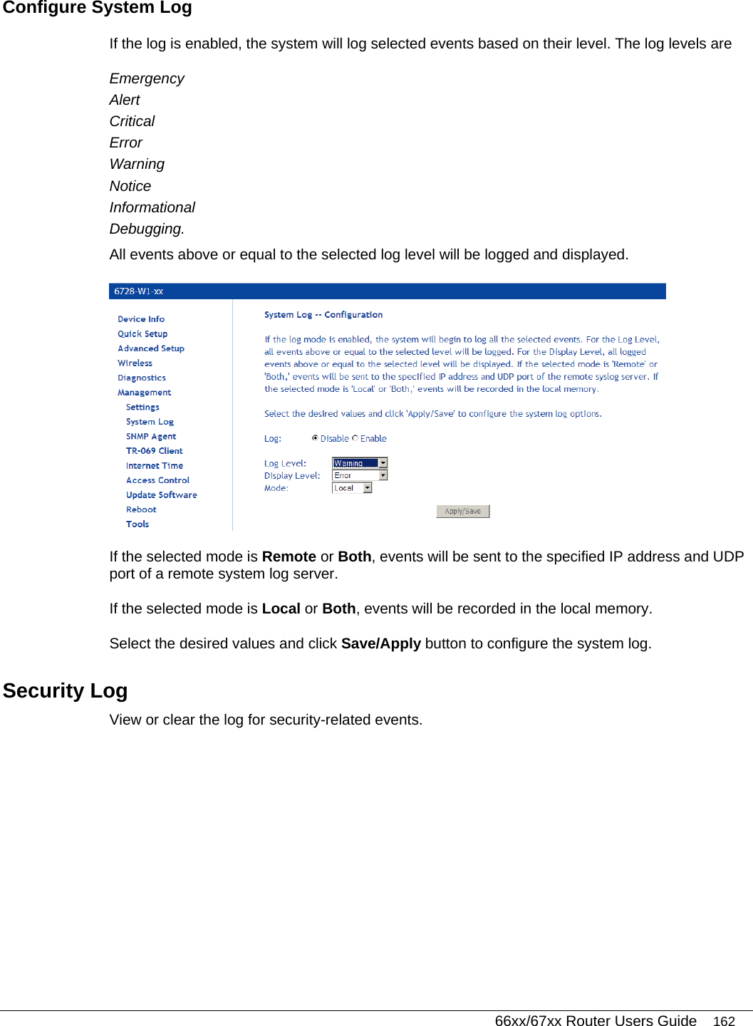
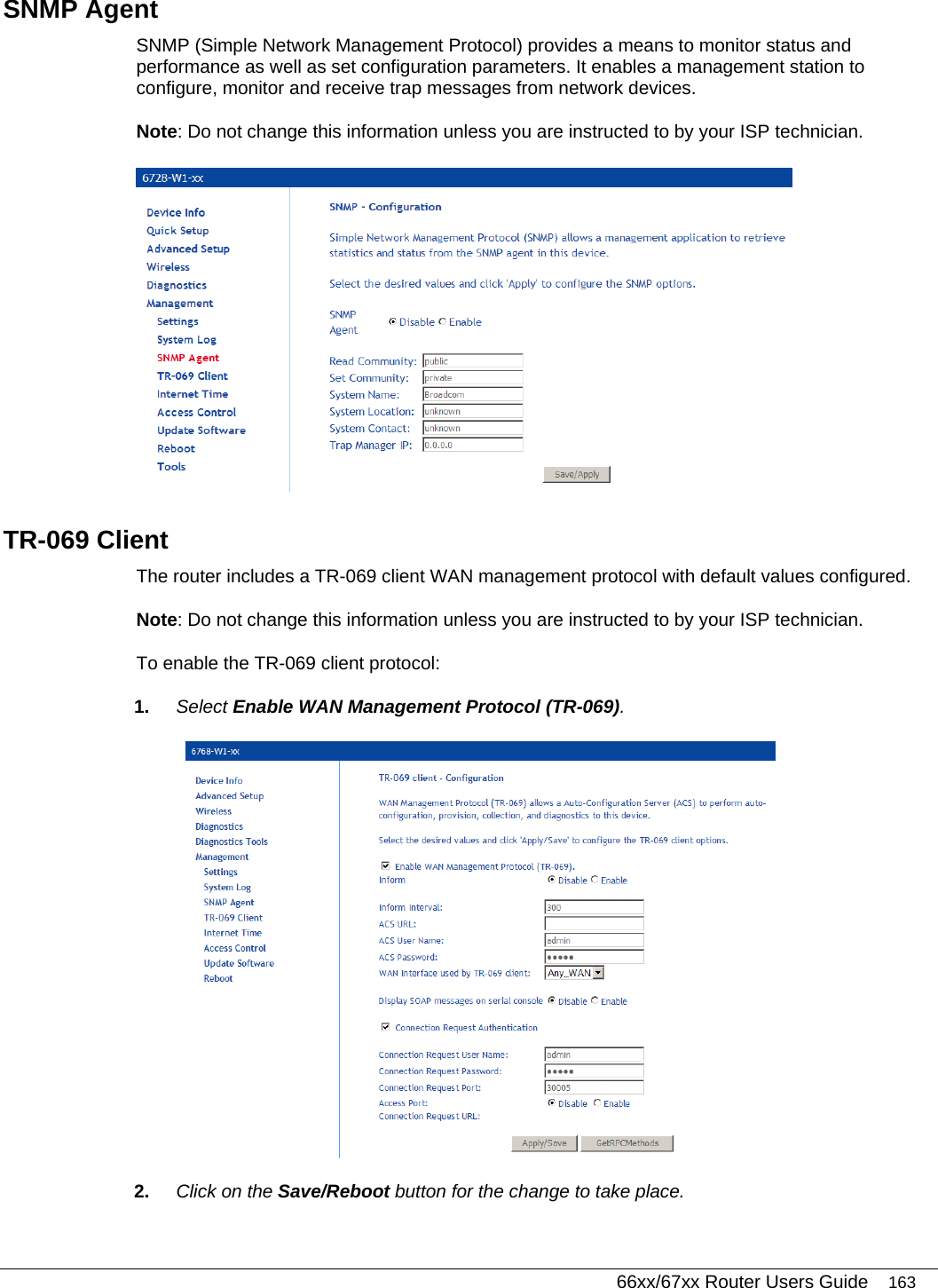
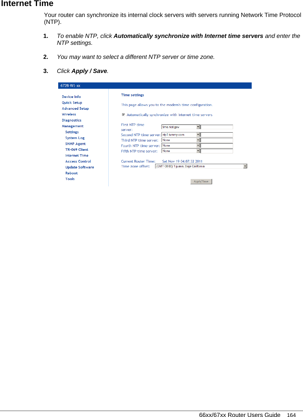
Users Manual
Navigation menu
Upload a User Manual
Namespaces
Wiki Guide
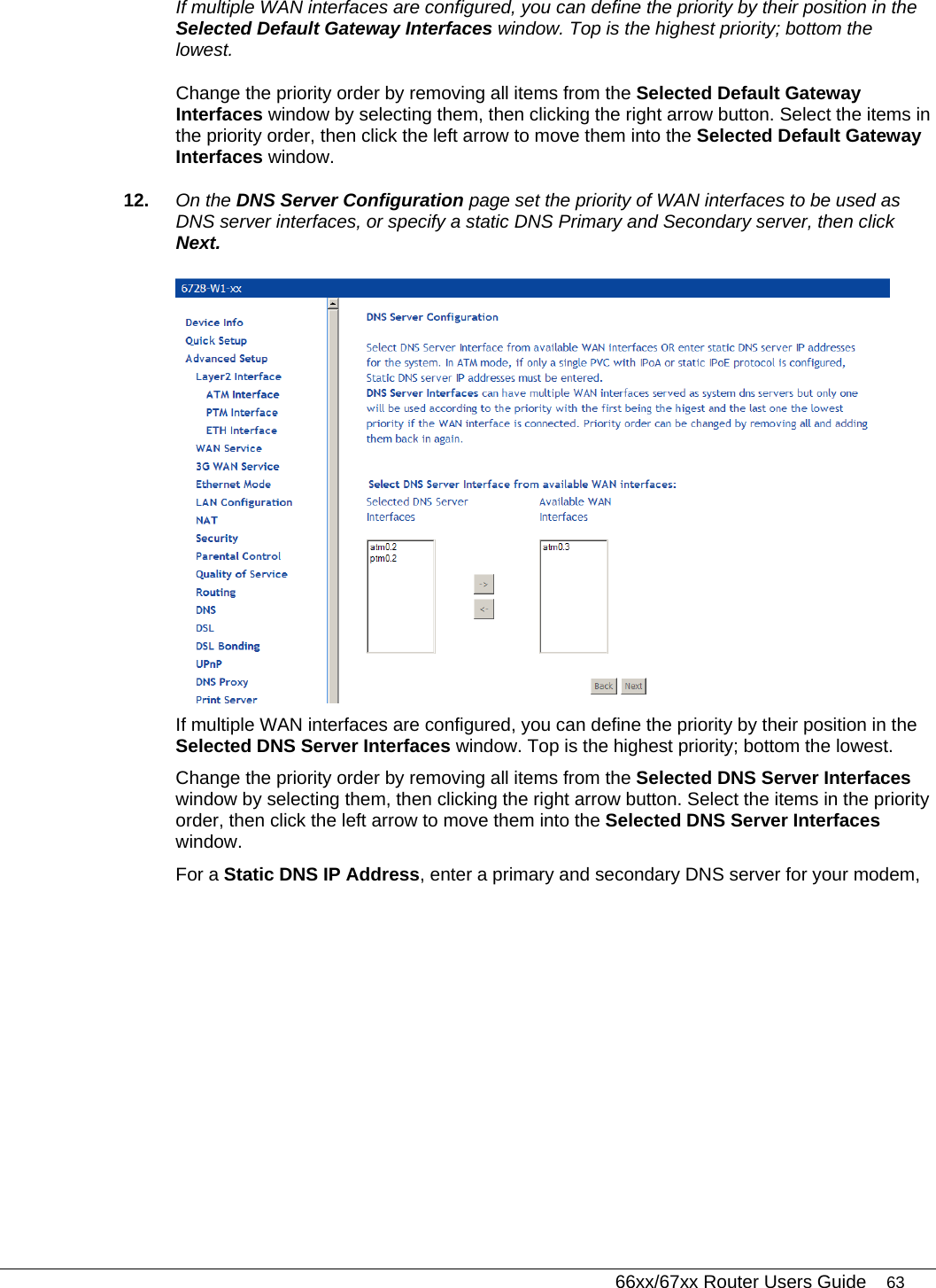
HTML
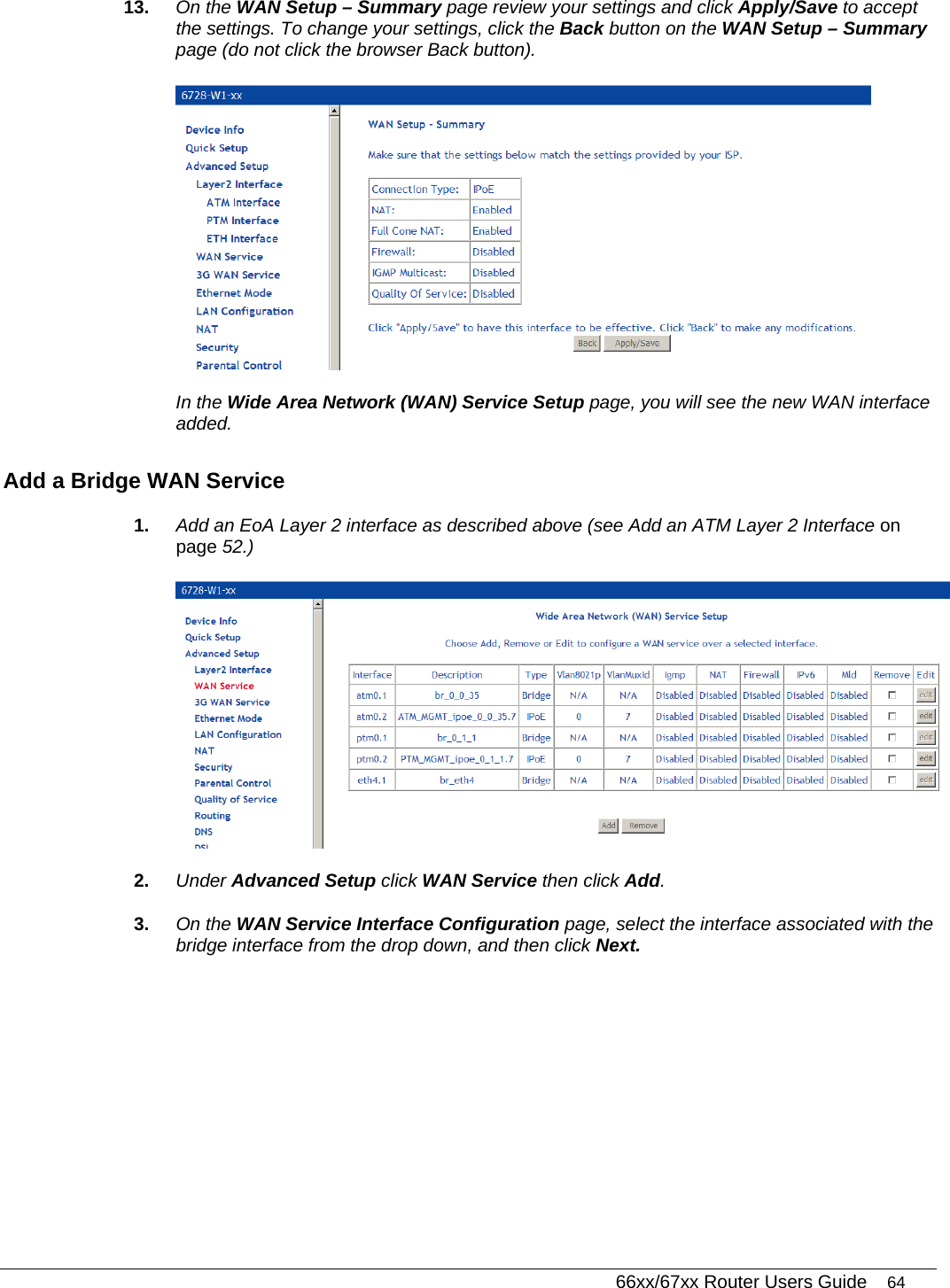
PDF
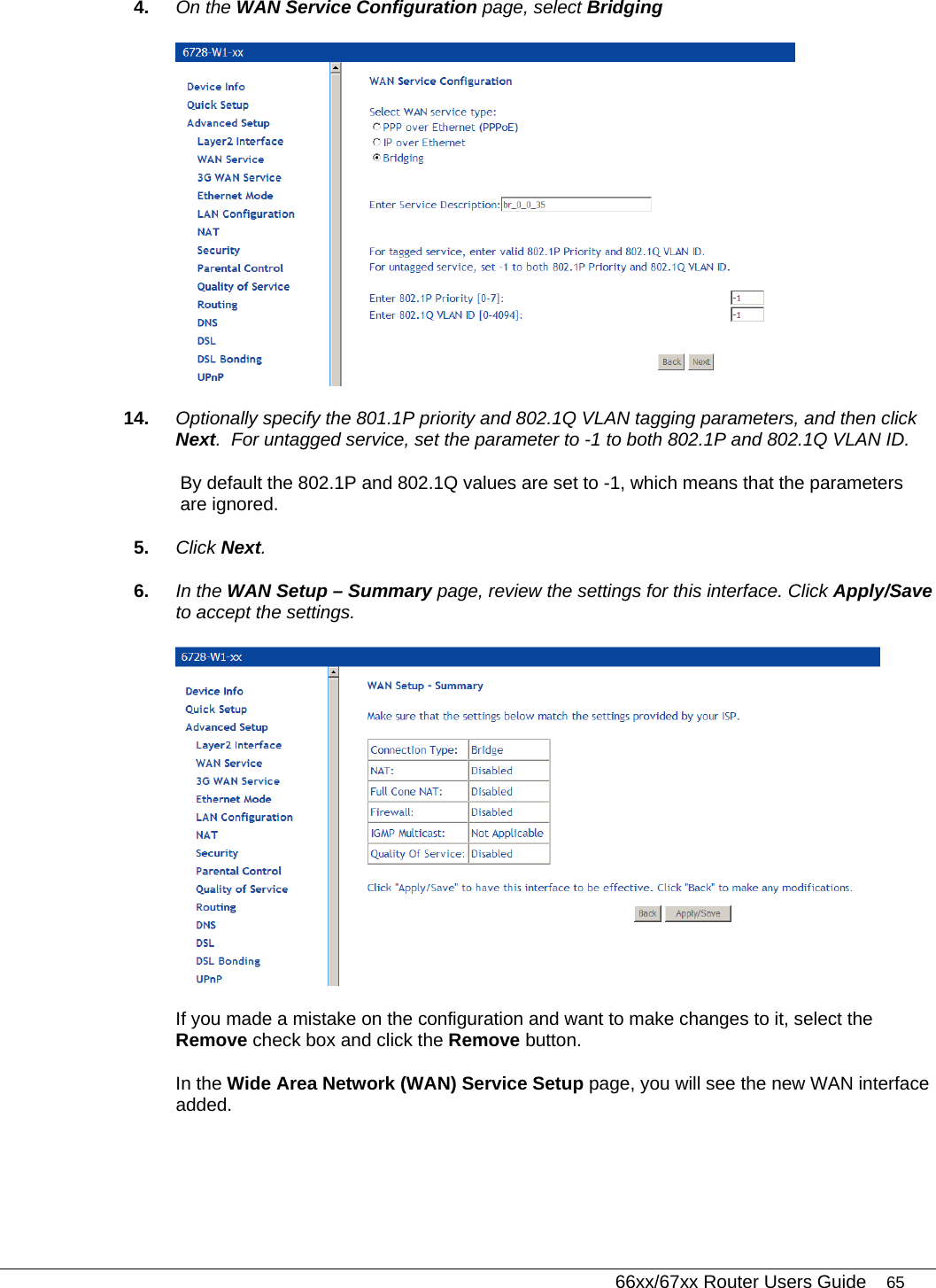
Info
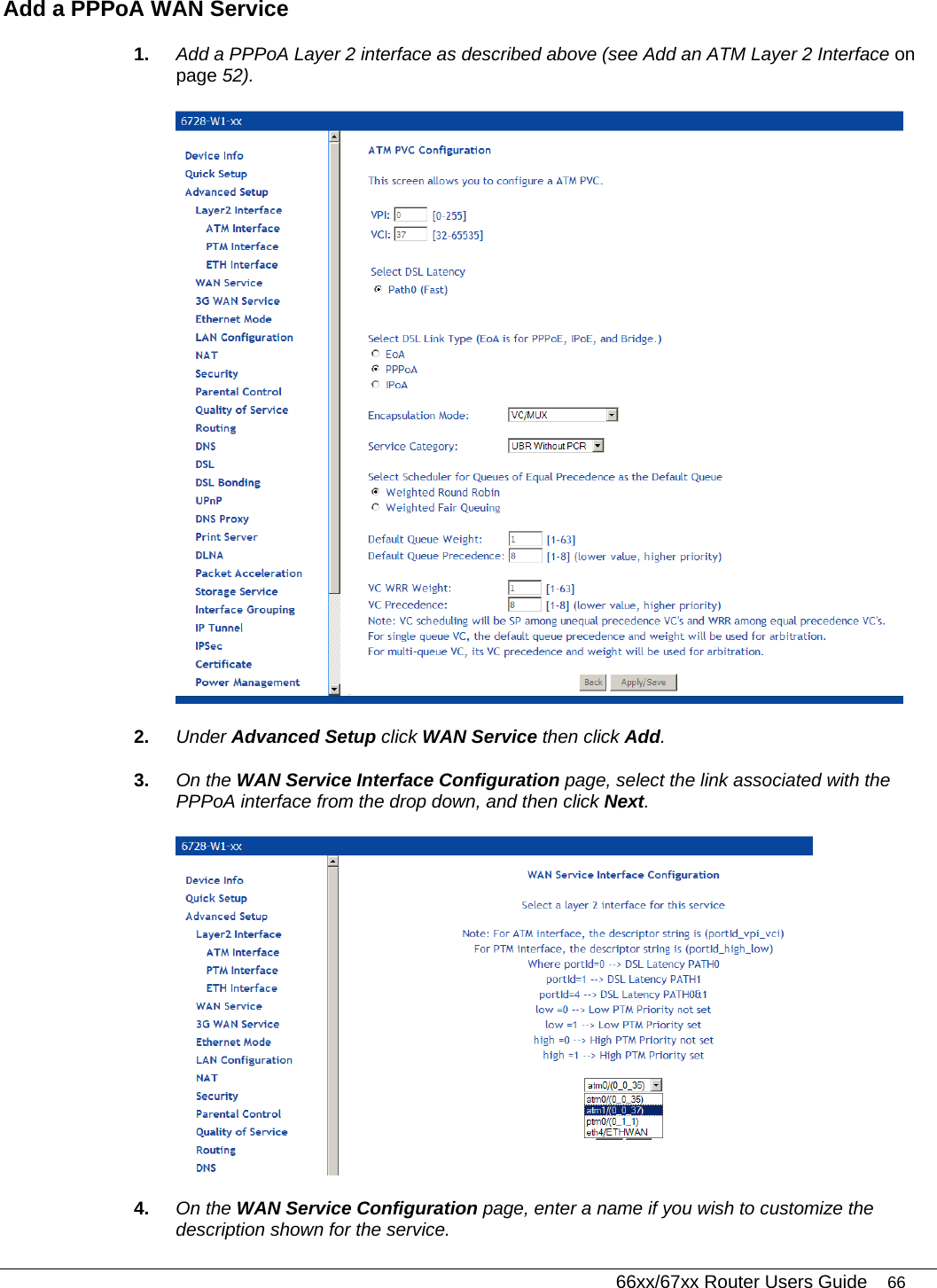
Views
User Manual
Discussion / Help
Navigation
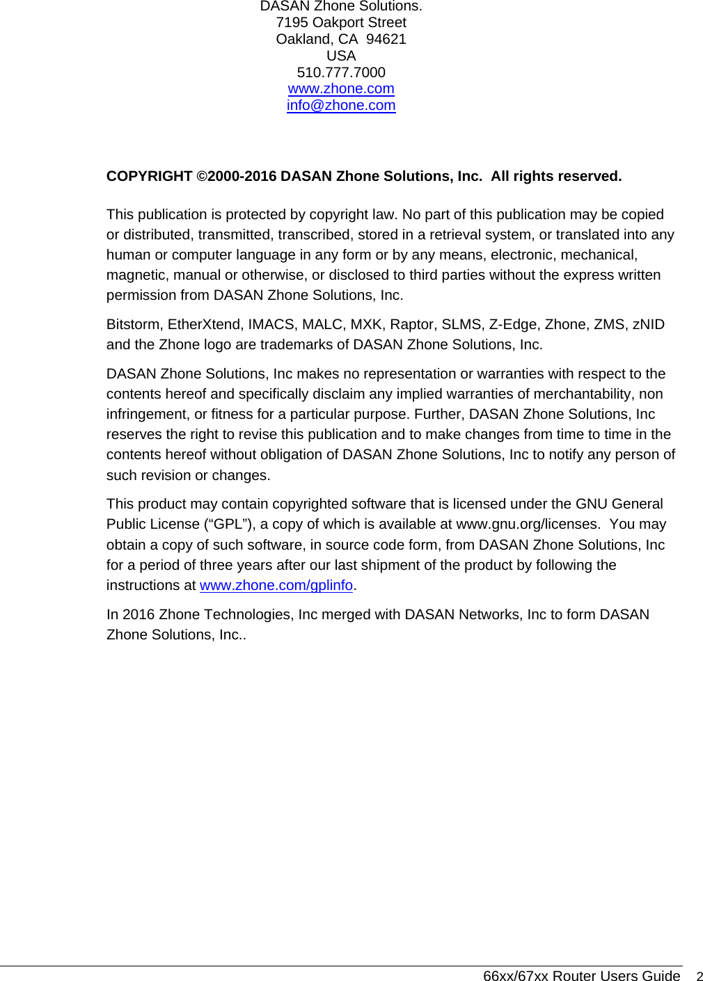
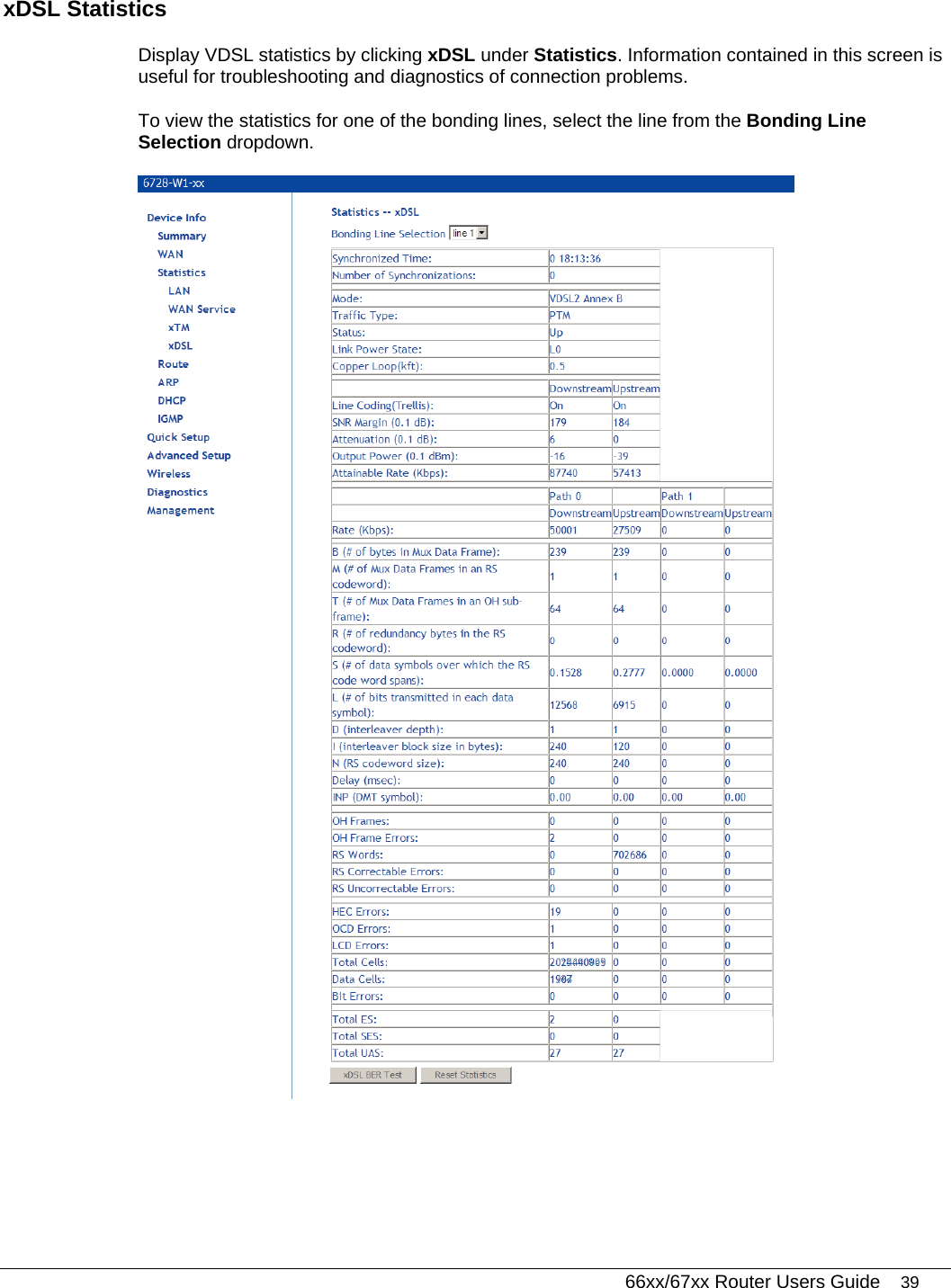
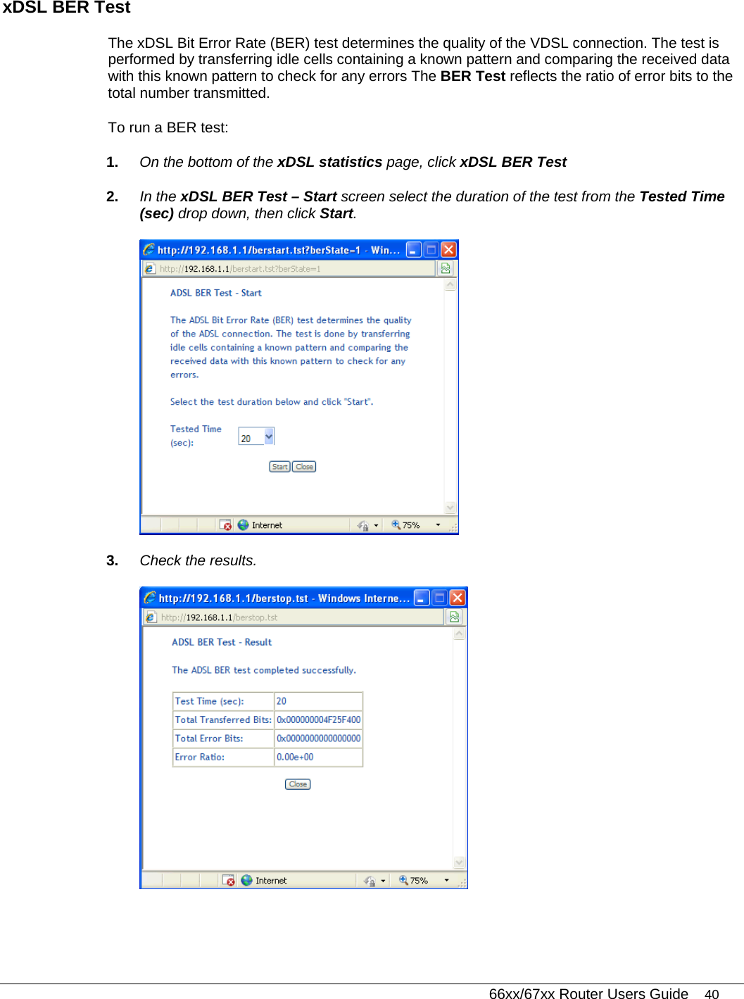
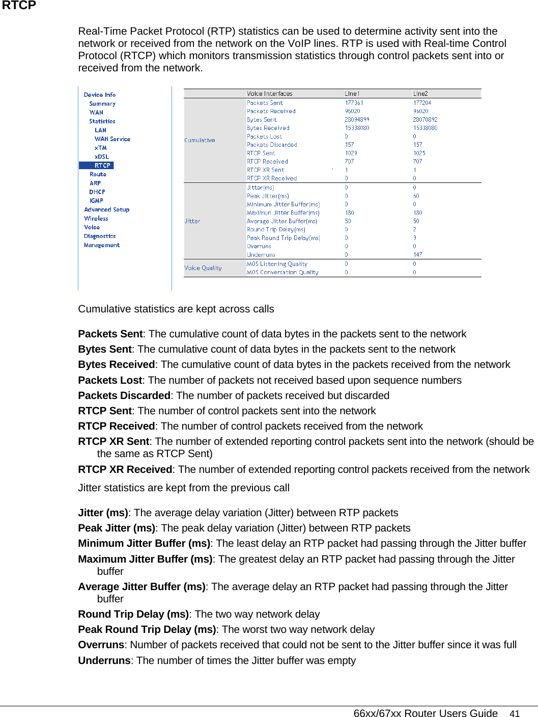
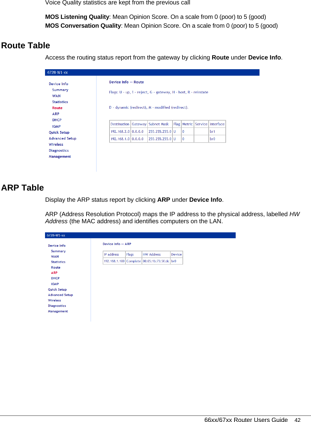
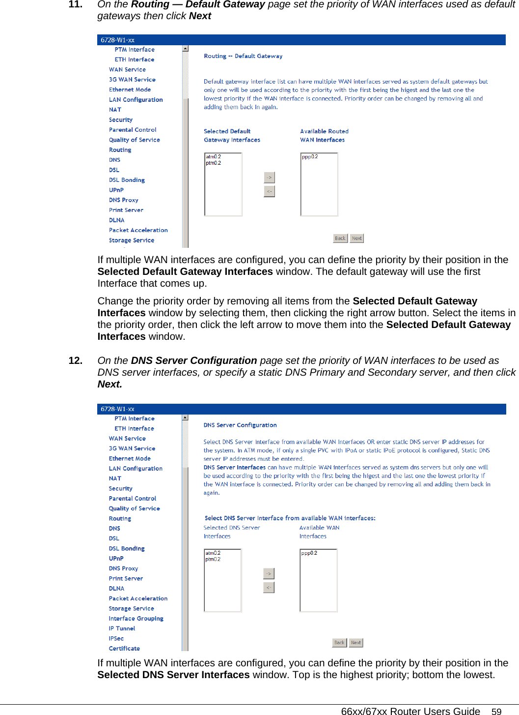
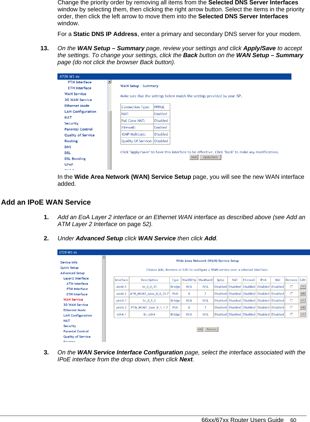
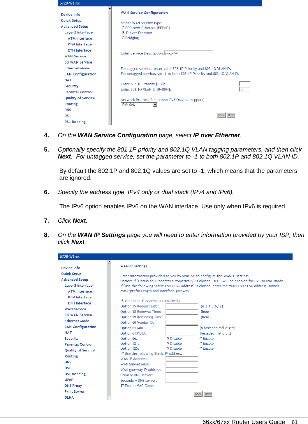
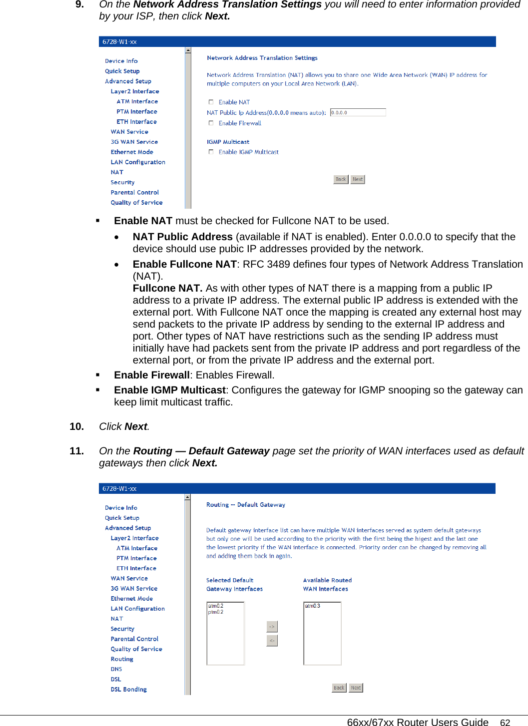
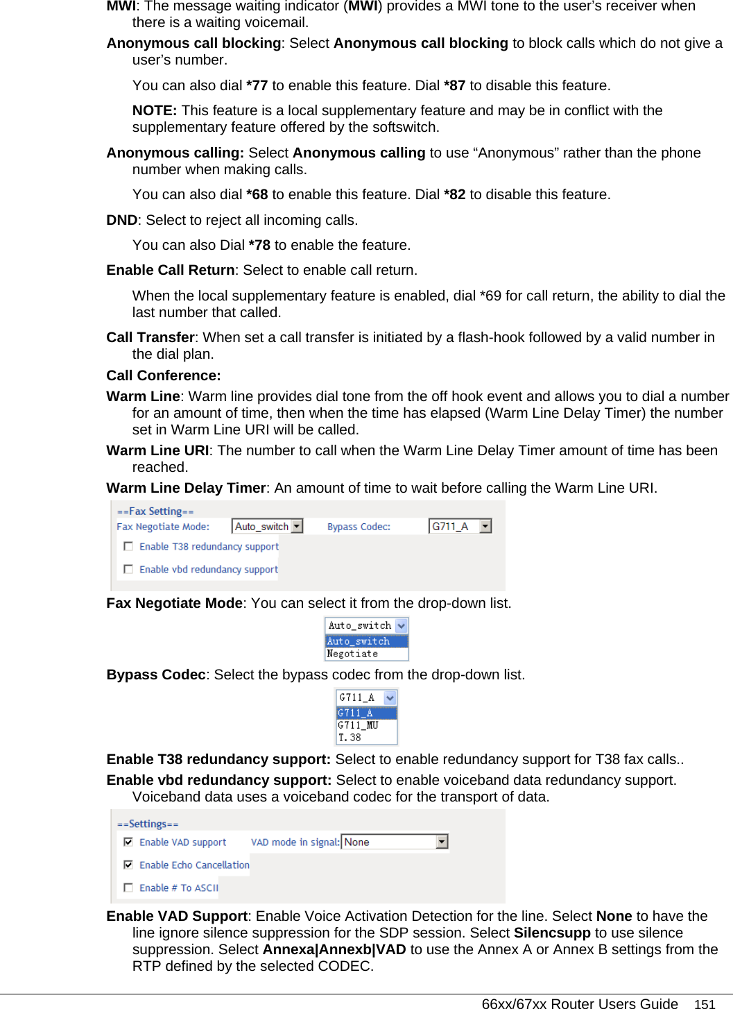
![66xx/67xx Router Users Guide 13 Typographical Conventions The following typographical styles are used in this guide to represent specific types of information. Bold Used for names of buttons, dialog boxes, icons, menus, profiles when placed in body text, and property pages (or sheets). Also used for commands, options, parameters in body text, and user input in body text. Fixed Used in code examples for computer output, file names, path names, and the contents of online files or directories. Fixed Bold Used in code examples for text typed by users. Fixed Bold Italic Used in code examples for variable text typed by users. Italic Used for book titles, chapter titles, file path names, notes in body text requiring special attention, section titles, emphasized terms, and variables. PLAIN UPPER CASE Used for environment variables. Command Syntax Brackets [ ] indicate optional syntax. Vertical bar | indicates the OR symbol. Acronyms The following acronyms are related to DZS products and may appear throughout this manual: Table 1: Acronyms and their descriptions Acronym Description ADSL Asymmetrical Digital Subscriber Line AP Access Point ACS Auto Configuration Server DHCP Dynamic Host Configuration Protocol DSL Digital Subscriber Line EFM Ethernet in the First Mile MALC Multi-Access Line Concentrator MIB Management Information Bases NAT Network Address Translation](https://usermanual.wiki/DASAN-Zhone-Solutions/6768/User-Guide-3288804-Page-13.png)
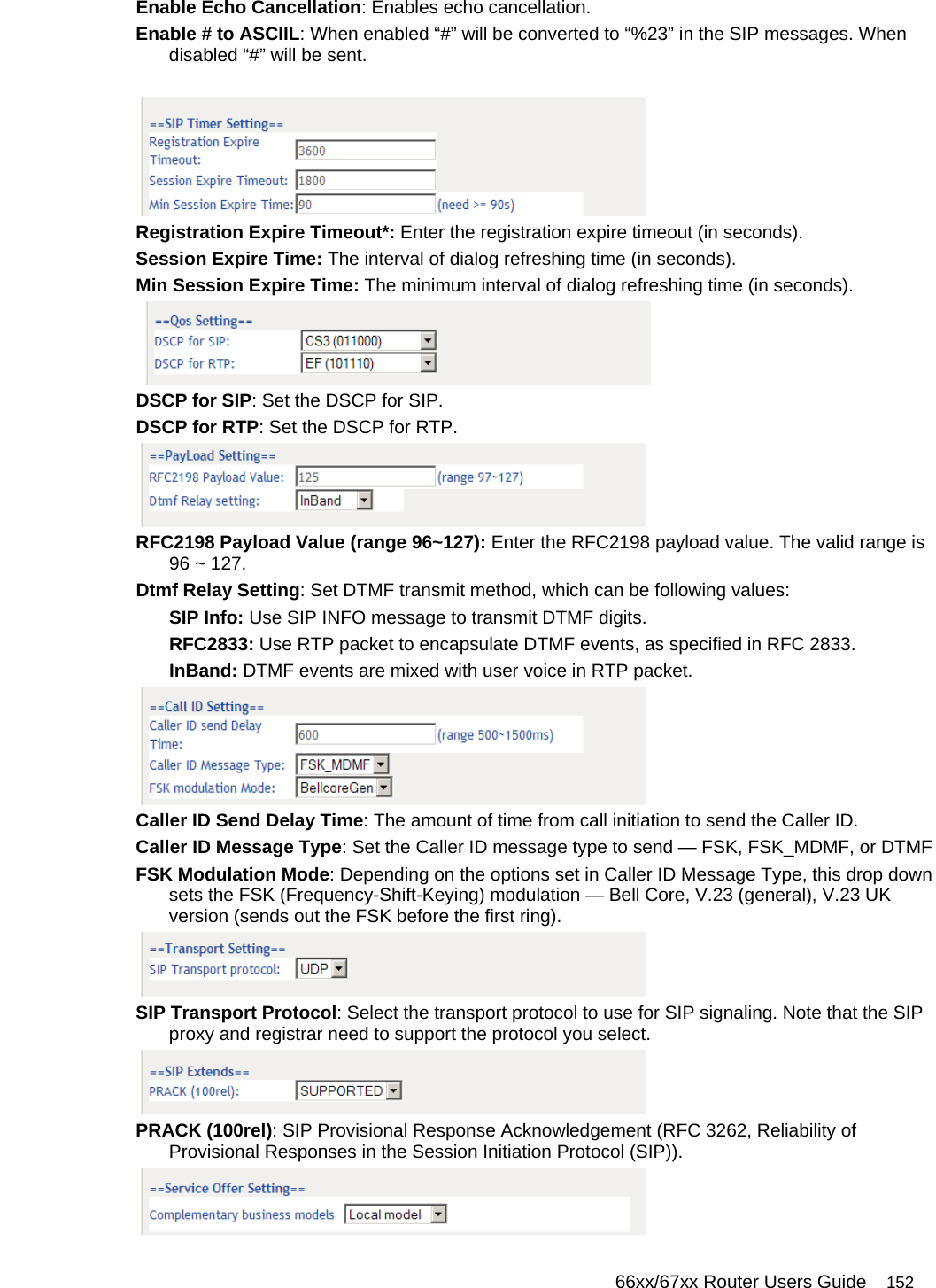
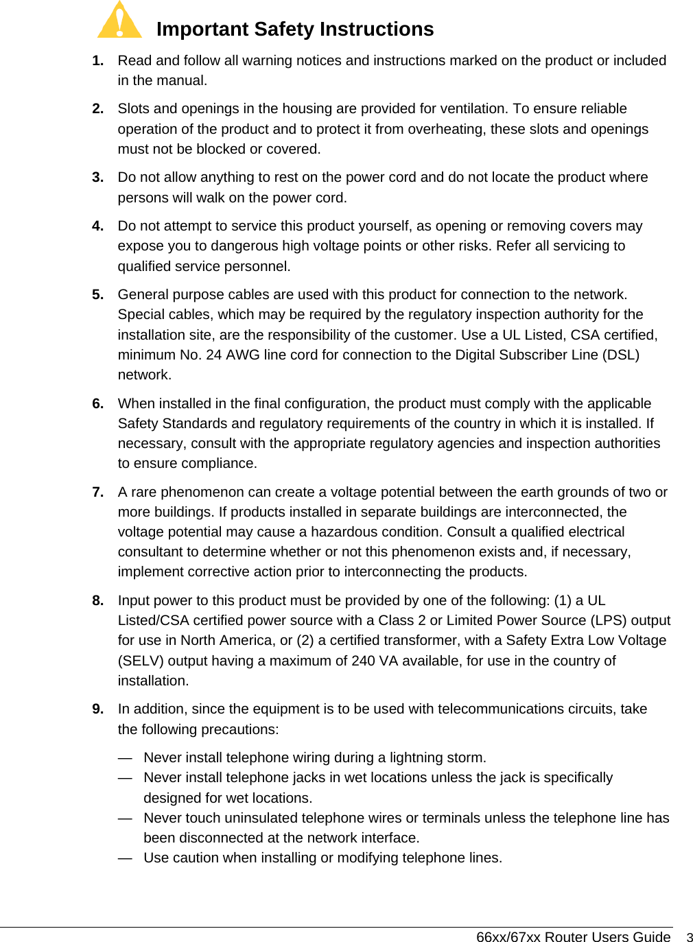
![66xx/67xx Router Users Guide 153 Complimentary Business Models Local Model: The service is supported by the gateway rather than by a SoftSwitch. Server Model: (for softx3000) Flash hook is sent via INFO. IMS Model: (for Hauwei, ZTE IMS) support FLASHHOOK and INFO modes. Undefined Enable Local Supplementary Service: Select to enable the supplementary service settings by the telephone set. If you deselect the checkbox, the supplementary service can not be set by the telephone set. Zhone recommends not selecting Local Supplementary Service. Not selecting Local Supplementary Service allows the softswitch to act upon the * codes based on the supplementary services offered by the softswitch. SIP Digit Map Settings A dialing plan for POTS-to-SIP outgoing calls consists of a series of acceptable dial strings. If an acceptable dialplan is not entered which matches one of the acceptable dial strings entered in the Digit Map Setting window, the call will not proceed. The following rules are used to configure the dialplan: Each dial string is represented as digits, wildcards, and regular-expression-like patterns. Digits “0” to “9” are allowed as well as “*” and “#”. The character “x” indicates a wildcard for 0 or more digits between 0-9. The character “T” or “t” designates an override for the interdigit timeout. Brackets “[]” define digit range. [135] means digits 1, 3, or 5. [1-4] means digits 1, 2, 3, or 4. The use of “.” represents any digit and a ‘|’ character indicates an inclusive OR, so “*.xT | x.T “ indicates star plus any number of digits followed by the inter-digit timeout.](https://usermanual.wiki/DASAN-Zhone-Solutions/6768/User-Guide-3288804-Page-153.png)
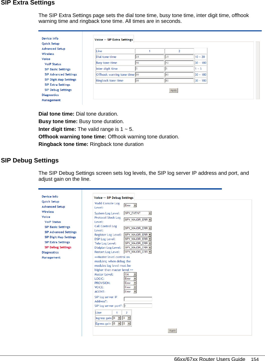

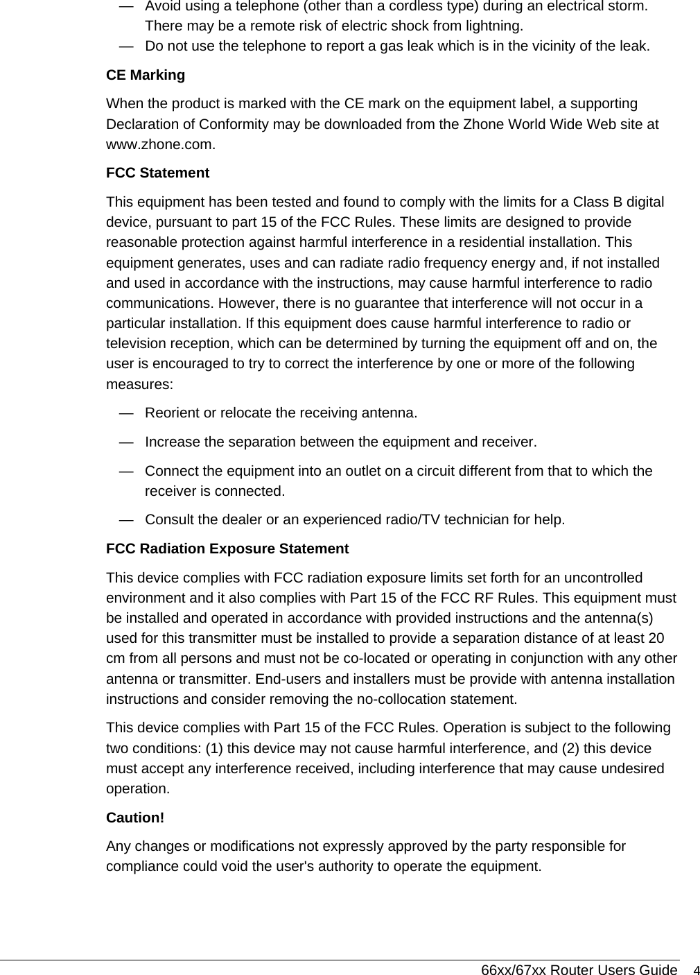
![66xx/67xx Router Users Guide 174 There may be several addresses associated with an Internet name. This is common for web sites that receive heavy traffic; they use multiple, redundant servers to carry the same information. 3. To exit from the nslookup utility, type exit and press [Enter] at the command prompt.](https://usermanual.wiki/DASAN-Zhone-Solutions/6768/User-Guide-3288804-Page-174.png)