DASAN Zhone Solutions 6768 XDSL 4 Port WiFi 802.11ac Gateway User Manual 66xx 67xx UG 01232016
DASAN Zhone Solutions, Inc. XDSL 4 Port WiFi 802.11ac Gateway 66xx 67xx UG 01232016
Users Manual
66xx/67xx-W1
VDSL2/ADSL2+
Gateway Users Guide
Document Part Number: 830-04091-03
January, 2017

66xx/67xx Router Users Guide 2
DASAN Zhone Solutions.
7195 Oakport Street
Oakland, CA 94621
USA
510.777.7000
www.zhone.com
info@zhone.com
COPYRIGHT ©2000-2016 DASAN Zhone Solutions, Inc. All rights reserved.
This publication is protected by copyright law. No part of this publication may be copied
or distributed, transmitted, transcribed, stored in a retrieval system, or translated into any
human or computer language in any form or by any means, electronic, mechanical,
magnetic, manual or otherwise, or disclosed to third parties without the express written
permission from DASAN Zhone Solutions, Inc.
Bitstorm, EtherXtend, IMACS, MALC, MXK, Raptor, SLMS, Z-Edge, Zhone, ZMS, zNID
and the Zhone logo are trademarks of DASAN Zhone Solutions, Inc.
DASAN Zhone Solutions, Inc makes no representation or warranties with respect to the
contents hereof and specifically disclaim any implied warranties of merchantability, non
infringement, or fitness for a particular purpose. Further, DASAN Zhone Solutions, Inc
reserves the right to revise this publication and to make changes from time to time in the
contents hereof without obligation of DASAN Zhone Solutions, Inc to notify any person of
such revision or changes.
This product may contain copyrighted software that is licensed under the GNU General
Public License (“GPL”), a copy of which is available at www.gnu.org/licenses. You may
obtain a copy of such software, in source code form, from DASAN Zhone Solutions, Inc
for a period of three years after our last shipment of the product by following the
instructions at www.zhone.com/gplinfo.
In 2016 Zhone Technologies, Inc merged with DASAN Networks, Inc to form DASAN
Zhone Solutions, Inc..

66xx/67xx Router Users Guide 3
Important Safety Instructions
1. Read and follow all warning notices and instructions marked on the product or included
in the manual.
2. Slots and openings in the housing are provided for ventilation. To ensure reliable
operation of the product and to protect it from overheating, these slots and openings
must not be blocked or covered.
3. Do not allow anything to rest on the power cord and do not locate the product where
persons will walk on the power cord.
4. Do not attempt to service this product yourself, as opening or removing covers may
expose you to dangerous high voltage points or other risks. Refer all servicing to
qualified service personnel.
5. General purpose cables are used with this product for connection to the network.
Special cables, which may be required by the regulatory inspection authority for the
installation site, are the responsibility of the customer. Use a UL Listed, CSA certified,
minimum No. 24 AWG line cord for connection to the Digital Subscriber Line (DSL)
network.
6. When installed in the final configuration, the product must comply with the applicable
Safety Standards and regulatory requirements of the country in which it is installed. If
necessary, consult with the appropriate regulatory agencies and inspection authorities
to ensure compliance.
7. A rare phenomenon can create a voltage potential between the earth grounds of two or
more buildings. If products installed in separate buildings are interconnected, the
voltage potential may cause a hazardous condition. Consult a qualified electrical
consultant to determine whether or not this phenomenon exists and, if necessary,
implement corrective action prior to interconnecting the products.
8. Input power to this product must be provided by one of the following: (1) a UL
Listed/CSA certified power source with a Class 2 or Limited Power Source (LPS) output
for use in North America, or (2) a certified transformer, with a Safety Extra Low Voltage
(SELV) output having a maximum of 240 VA available, for use in the country of
installation.
9. In addition, since the equipment is to be used with telecommunications circuits, take
the following precautions:
— Never install telephone wiring during a lightning storm.
— Never install telephone jacks in wet locations unless the jack is specifically
designed for wet locations.
— Never touch uninsulated telephone wires or terminals unless the telephone line has
been disconnected at the network interface.
— Use caution when installing or modifying telephone lines.

66xx/67xx Router Users Guide 4
— Avoid using a telephone (other than a cordless type) during an electrical storm.
There may be a remote risk of electric shock from lightning.
— Do not use the telephone to report a gas leak which is in the vicinity of the leak.
CE Marking
When the product is marked with the CE mark on the equipment label, a supporting
Declaration of Conformity may be downloaded from the Zhone World Wide Web site at
www.zhone.com.
FCC Statement
This equipment has been tested and found to comply with the limits for a Class B digital
device, pursuant to part 15 of the FCC Rules. These limits are designed to provide
reasonable protection against harmful interference in a residential installation. This
equipment generates, uses and can radiate radio frequency energy and, if not installed
and used in accordance with the instructions, may cause harmful interference to radio
communications. However, there is no guarantee that interference will not occur in a
particular installation. If this equipment does cause harmful interference to radio or
television reception, which can be determined by turning the equipment off and on, the
user is encouraged to try to correct the interference by one or more of the following
measures:
— Reorient or relocate the receiving antenna.
— Increase the separation between the equipment and receiver.
— Connect the equipment into an outlet on a circuit different from that to which the
receiver is connected.
— Consult the dealer or an experienced radio/TV technician for help.
FCC Radiation Exposure Statement
This device complies with FCC radiation exposure limits set forth for an uncontrolled
environment and it also complies with Part 15 of the FCC RF Rules. This equipment must
be installed and operated in accordance with provided instructions and the antenna(s)
used for this transmitter must be installed to provide a separation distance of at least 20
cm from all persons and must not be co-located or operating in conjunction with any other
antenna or transmitter. End-users and installers must be provide with antenna installation
instructions and consider removing the no-collocation statement.
This device complies with Part 15 of the FCC Rules. Operation is subject to the following
two conditions: (1) this device may not cause harmful interference, and (2) this device
must accept any interference received, including interference that may cause undesired
operation.
Caution!
Any changes or modifications not expressly approved by the party responsible for
compliance could void the user's authority to operate the equipment.

66xx/67xx Router Users Guide 5
FCC - PART 68
This equipment complies with Part 68 of the FCC rules and the requirements adopted by
the ACTA. On the bottom of this equipment is a label that contains, among other
information, a product identifier in the format US: 6RTDL01A6768. If requested, this
number must be provided to the telephone company.
This equipment uses the following USOC jacks: RJ-11, RJ-45, USB Jack, Power Jack.
REN (RINGER EQUIVALENT NUMBERS) STATEMENT
Notice: The Ringer Equivalence Number (REN: 0.1) assigned to each terminal device
provides an indication of the maximum number of terminals allowed to be connected to a
telephone interface. The termination on an interface may consist of any combination of
devices subject only to the requirement that the sum of the Ringer Equivalence Numbers
of all the devices does not exceed 5.
ATTACHMENT LIMITATIONS STATEMENT
Notice: This equipment meets telecommunications network protective, operational and
safety requirements as prescribed in the appropriate Terminal Equipment Technical
Requirements document(s). This is confirmed by marking the equipment with the Industry
Canada certification number. The Department does not guarantee the equipment will
operate to the user's satisfaction.
Before installing this equipment, users should ensure that it is permissible to be
connected to the facilities of the local telecommunications company. The equipment must
also be installed using an acceptable method of connection. The customer should be
aware that compliance with the above conditions may not prevent degradation of service
in some situations.
Repairs to certified equipment should be coordinated by a representative designated by
the supplier. Any repairs or alterations made by the user to this equipment, or equipment
malfunctions, may give the telecommunications company cause to request the user to
disconnect the equipment.
Users should ensure for their own protection that the electrical ground connections of the
power utility, telephone lines and internal metallic water pipe system, if present, are
connected together.
This precaution may be particularly important in rural areas. Caution: Users should not
attempt to make such connections themselves, but should contact the appropriate
electric inspection authority, or electrician, as appropriate
CS-03
This product meets the applicable Innovation, Science and Economic Development
Canada technical specifications.
The Ringer Equivalence Number (REN=0.1) indicates the maximum number of devices
allowed to be connected to a telephone interface. The termination of an interface may
consist of any combination of devices subject only to the requirement that the sum of the
RENs of all the devices not exceed five.

66xx/67xx Router Users Guide 6
Le présent produit est conforme aux spécifications techniques applicables d'Innovation,
Sciences et Développement économique Canada.
L'indice d'équivalence de la sonnerie (IES=0.1) sert à indiquer le nombre maximal de
dispositifs qui peuvent être raccordés à une interface téléphonique. La terminaison d'une
interface peut consister en une combinaison quelconque de dispositifs, à la seule
condition que la somme des IES de tous les dispositifs n'excède pas cinq.
Canada Statement
This device complies with Industry Canada’s licence-exempt RSSs. Operation is subject
to the following two conditions:
(1) This device may not cause interference; and
(2) This device must accept any interference, including interference that may cause
undesired operation of the device.
Le présent appareil est conforme aux CNR d’Industrie Canada applicables aux appareils
radio exempts de licence. L’exploitation est autorisée aux deux conditions suivantes :
(1) l’appareil ne doit pas produire de brouillage;
(2) l’utilisateur de l’appareil doit accepter tout brouillage radioélectrique subi, même si le
brouillage est susceptible d’en compromettre le fonctionnement.
The device meets the exemption from the routine evaluation limits in section 2.5 of RSS
102 and compliance with RSS-102 RF exposure, users can obtain Canadian information
on RF exposure and compliance.
Le dispositif rencontre l'exemption des limites courantes d'évaluation dans la section 2.5
de RSS 102 et la conformité à l'exposition de RSS-102 rf, utilisateurs peut obtenir
l'information canadienne sur l'exposition et la conformité de rf.
This transmitter must not be co-located or operating in conjunction with any other
antenna or transmitter. This equipment should be installed and operated with a minimum
distance of 20 centimeters between the radiator and your body.
Cet émetteur ne doit pas être Co-placé ou ne fonctionnant en même temps qu'aucune
autre antenne ou émetteur. Cet équipement devrait être installé et actionné avec une
distance minimum de 20 centimètres entre le radiateur et votre corps.
the device for operation in the band 5150-5250 MHz is only for indoor use to reduce the
potential for harmful interference to co-channel mobile satellite systems
les dispositifs fonctionnant dans la bande 5150-5250 MHz sont réservés uniquement
pour une utilisation à l’intérieur afin de réduire les risques de brouillage préjudiciable aux
systèmes de satellites mobiles utilisant les mêmes canaux.
Users should also be advised that high-power radars are allocated as primary users (i.e.
priority users) of the bands 5250-5350 MHz and 5650-5850 MHz and that these radars
could cause interference and/or damage to LE-LAN devices.
les utilisateurs de radars de haute puissance sont désignés utilisateurs principaux (c.-à-
d., qu'ils ont la priorité) des bandes de 5 250 à 5 350 MHz et de 5 650 à 5 850 MHz et,

66xx/67xx Router Users Guide 7
d’autre part, que ces radars pourraient causer du brouillage et/ou des dommages aux
dispositifs de RL-EL.
Canada - EMI Notice:
This Class B digital apparatus meets all requirements of the Canadian interference-
causing equipment regulations.
Cet appareil numérique de la classe B respecte toutes les exigences du règlement sur le
matérial brouilleur du Canada.
NOTICE: This device complies with RSS-210,IC ID: 6391A-6519-W1, 6391A-67x8-W1,
6391A-673x. Operation is subject to the following two conditions:
1. This device may not cause interference and
2. This device must accept any interference, including interference that may cause
undesired operation of the device.

66xx/67xx Router Users Guide 8
Table of Contents
Important Safety Instructions.................................................................................................................... 3
CE Marking........................................................................................................................................... 4
FCC Statement..................................................................................................................................... 4
FCC Radiation Exposure Statement .................................................................................................... 4
Caution! ................................................................................................................................................ 4
FCC - PART 68..................................................................................................................................... 5
REN (RINGER EQUIVALENT NUMBERS) STATEMENT ................................................................... 5
ATTACHMENT LIMITATIONS STATEMENT........................................................................................ 5
CS-03 ................................................................................................................................................... 5
Canada Statement................................................................................................................................ 6
Canada - EMI Notice:....................................................................................................................... 7
Table of Contents...................................................................................................................................... 8
About This Guide .................................................................................................................................... 12
Style and Notation Conventions ......................................................................................................... 12
Typographical Conventions................................................................................................................ 13
Acronyms............................................................................................................................................ 13
Contacting Customer Service and Technical Support ............................................................................ 14
Chapter 1 Introduction 15
Protocol Support ..................................................................................................................................... 16
System Requirements ............................................................................................................................ 17
Package Contents................................................................................................................................... 17
Safety Instructions .................................................................................................................................. 18
Models .................................................................................................................................................... 19
Front Panel ............................................................................................................................................. 25
LED Descriptions................................................................................................................................ 25
Back Panel.............................................................................................................................................. 27
Side Panel............................................................................................................................................... 28
Unit Dimensions...................................................................................................................................... 28
Wall Mount .............................................................................................................................................. 29
Chapter 2 Hardware Installation and PC Setup 30
Overview................................................................................................................................................. 30
Connecting Your Hardware..................................................................................................................... 30
Configuring Your Computer .................................................................................................................... 33
Windows 2000.................................................................................................................................... 33
Windows XP ....................................................................................................................................... 34
Windows 7.......................................................................................................................................... 34
Chapter 3 The Web User Interface 35
Log in to the Gateway............................................................................................................................. 35
Summary................................................................................................................................................. 36
WAN Information..................................................................................................................................... 37
Statistics ............................................................................................................................................. 37
LAN Statistics ..................................................................................................................................... 37
WAN Statistics .................................................................................................................................... 38
xTM Statistics ..................................................................................................................................... 38
xDSL Statistics.................................................................................................................................... 39
xDSL BER Test................................................................................................................................... 40
RTCP.................................................................................................................................................. 41

66xx/67xx Router Users Guide 9
Route Table............................................................................................................................................. 42
ARP Table............................................................................................................................................... 42
DHCP Table ............................................................................................................................................ 43
IGMP....................................................................................................................................................... 43
System Performance .............................................................................................................................. 44
Chapter 4 Quick Setup 45
Quick Setup with Automatic Configuration ............................................................................................. 45
Quick Setup with Automatic Configuration Disabled .............................................................................. 47
Chapter 5 Advanced Setup 51
Configuration Types................................................................................................................................ 51
Add an ATM Layer 2 Interface ................................................................................................................ 52
Add a PTM Layer 2 Interface.................................................................................................................. 54
Add an Ethernet Layer 2 WAN Interface ................................................................................................ 55
WAN Service........................................................................................................................................... 55
Add a PPPoE WAN Service ............................................................................................................... 56
Add an IPoE WAN Service................................................................................................................. 60
Add a Bridge WAN Service ................................................................................................................ 64
Add a PPPoA WAN Service ............................................................................................................... 66
Add an IPoA WAN Service ................................................................................................................. 69
Remove a Connection........................................................................................................................ 72
Edit a Connection ............................................................................................................................... 72
3G WAN Service..................................................................................................................................... 72
USB Modem Service .............................................................................................................................. 73
VPN......................................................................................................................................................... 74
Ethernet Mode ........................................................................................................................................ 75
LAN Local Area Network (LAN) Setup ................................................................................................... 76
IPv4 Configuration.............................................................................................................................. 76
IPv6 Configuration.............................................................................................................................. 79
LAN VLAN Setup................................................................................................................................ 80
NAT ......................................................................................................................................................... 81
Virtual Servers.................................................................................................................................... 81
Port Triggering.................................................................................................................................... 82
DMZ Host ........................................................................................................................................... 83
ALG .................................................................................................................................................... 84
Security................................................................................................................................................... 85
Firewall ............................................................................................................................................... 85
Add a firewall...................................................................................................................................... 86
Add a rule ........................................................................................................................................... 86
IP Filtering .......................................................................................................................................... 88
MAC Filtering...................................................................................................................................... 90
Parental Control...................................................................................................................................... 92
Time Restriction.................................................................................................................................. 92
URL Filter............................................................................................................................................ 93
Quality of Service.................................................................................................................................... 94
Queue Config ..................................................................................................................................... 94
WLAN Queue ..................................................................................................................................... 96
QoS Classification .............................................................................................................................. 96
QoS Port Shaping............................................................................................................................... 98
Routing.................................................................................................................................................... 99
Default Gateway................................................................................................................................. 99
Static Route ........................................................................................................................................ 99
Policy Routing................................................................................................................................... 100

66xx/67xx Router Users Guide 10
RIP.................................................................................................................................................... 100
DNS ...................................................................................................................................................... 101
DNS Server ...................................................................................................................................... 101
Dynamic DNS................................................................................................................................... 102
DSL....................................................................................................................................................... 103
DSL parameters................................................................................................................................ 104
Modulation Methods..................................................................................................................... 104
Profile Settings............................................................................................................................. 104
USO.............................................................................................................................................. 104
Capability...................................................................................................................................... 105
AuxFeature................................................................................................................................... 105
DSL Advanced Settings.................................................................................................................... 105
DSL Bonding......................................................................................................................................... 107
UPnP..................................................................................................................................................... 108
DNS Proxy ............................................................................................................................................ 108
Basic Configuration .......................................................................................................................... 108
Server Configuration ........................................................................................................................ 108
Print Server........................................................................................................................................... 109
Adding a printer server ..................................................................................................................... 109
Windows 7.................................................................................................................................... 109
Windows XP................................................................................................................................. 114
DLNA .................................................................................................................................................... 118
Packet Acceleration .............................................................................................................................. 118
Storage Service .................................................................................................................................... 119
Storage Device Info .......................................................................................................................... 119
User Accounts .................................................................................................................................. 119
Interface Grouping................................................................................................................................ 121
IP Tunnel............................................................................................................................................... 122
IPv6inIPv4 ........................................................................................................................................ 122
IPv4inIPv6 ........................................................................................................................................ 123
IPSec .................................................................................................................................................... 124
Certificate.............................................................................................................................................. 125
Local................................................................................................................................................. 125
Trusted CA........................................................................................................................................ 127
Power Management.............................................................................................................................. 128
Multicast................................................................................................................................................ 128
Wireless ................................................................................................................................................ 129
5Gand 2.4G...................................................................................................................................... 130
Basic................................................................................................................................................. 131
Security............................................................................................................................................. 133
WPS setup ................................................................................................................................... 133
Manual Setup AP ......................................................................................................................... 134
MAC Filter......................................................................................................................................... 139
Wireless Bridge ................................................................................................................................ 140
Advanced.......................................................................................................................................... 142
Station Info........................................................................................................................................ 144
WiFi Passpoint.................................................................................................................................. 145
Voice ..................................................................................................................................................... 146
VoIP Status ....................................................................................................................................... 146
SIP Basic Settings (Admin) .............................................................................................................. 147
SIP Basic Settings (User)................................................................................................................. 149
SIP Advanced Settings..................................................................................................................... 150
SIP Digit Map Settings...................................................................................................................... 153
SIP Extra Settings ............................................................................................................................ 154
SIP Debug Settings .......................................................................................................................... 154
Diagnostics ........................................................................................................................................... 156

66xx/67xx Router Users Guide 11
Fault Management............................................................................................................................ 157
Ethernet OAM................................................................................................................................... 157
Management......................................................................................................................................... 159
Settings............................................................................................................................................. 159
Backup Settings ........................................................................................................................... 159
Update Settings............................................................................................................................ 159
Restore Default ............................................................................................................................ 160
System Log........................................................................................................................................... 161
Configure System Log...................................................................................................................... 162
Security Log.......................................................................................................................................... 162
SNMP Agent ......................................................................................................................................... 163
TR-069 Client........................................................................................................................................ 163
Internet Time......................................................................................................................................... 164
Access Control...................................................................................................................................... 165
Passwords........................................................................................................................................ 165
Services Control ............................................................................................................................... 166
IP Addresses......................................................................................................................................... 167
Update Software ................................................................................................................................... 168
Reboot .................................................................................................................................................. 169
Diagnostic Tools.................................................................................................................................... 170
Chapter 6 Troubleshooting 171
The Router Is Not Functional................................................................................................................ 171
You Cannot Connect to the Router....................................................................................................... 171
The DSL LED Continues to Blink.......................................................................................................... 171
The DSL LED is Always Off .................................................................................................................. 172
The Internet LED is Always Off............................................................................................................. 172
The Internet LED is Red ....................................................................................................................... 172
Diagnosing Problems using IP Utilities................................................................................................. 172
Ping .................................................................................................................................................. 172
Tracert .............................................................................................................................................. 173
Nslookup........................................................................................................................................... 173
Appendix A – Glossary 175
66xx/67xx Router Users Guide 12
About This Guide
This guide is intended for use by installation technicians, system administrators, and
network administrators. It explains how to install and configure the 66xx/67xx family of
routers/gateways.
Style and Notation Conventions
The following conventions are used in this document to alert users to information that is
instructional, warns of potential damage to system equipment or data, and warns of
potential injury or death. Carefully read and follow the instructions included in this
document.
Caution: A caution alerts users to conditions or actions that could damage equipment or
data.
Note: A note provides important supplemental or amplified information.
Tip: A tip provides additional information that enables users to more readily complete their
tasks.
WARNING! A warning alerts users to conditions or actions that could lead to injury or death.

66xx/67xx Router Users Guide 13
Typographical Conventions
The following typographical styles are used in this guide to represent specific types of
information.
Bold Used for names of buttons, dialog boxes, icons, menus,
profiles when placed in body text, and property pages (or
sheets). Also used for commands, options, parameters in
body text, and user input in body text.
Fixed Used in code examples for computer output, file names, path
names, and the contents of online files or directories.
Fixed Bold Used in code examples for text typed by users.
Fixed Bold
Italic
Used in code examples for variable text typed by users.
Italic Used for book titles, chapter titles, file path names, notes in
body text requiring special attention, section titles,
emphasized terms, and variables.
PLAIN UPPER
CASE
Used for environment variables.
Command Syntax Brackets [ ] indicate optional syntax.
Vertical bar | indicates the OR symbol.
Acronyms
The following acronyms are related to DZS products and may appear throughout this
manual:
Table 1: Acronyms and their descriptions
Acronym Description
ADSL Asymmetrical Digital Subscriber Line
AP Access Point
ACS Auto Configuration Server
DHCP Dynamic Host Configuration Protocol
DSL Digital Subscriber Line
EFM Ethernet in the First Mile
MALC Multi-Access Line Concentrator
MIB Management Information Bases
NAT Network Address Translation

66xx/67xx Router Users Guide 14
Acronym Description
NMS Network Management System
PVC Permanent Virtual Circuit
RADIUS Remote Authentication Dial In User Service
SHDSL Symmetric High-bit-rate Digital Subscriber Line
SLMS Single Line Multi-Service
SNMP Simple Network Management Protocol
TFTP Trivial File Transfer Protocol
VoIP Voice over IP
VPN Virtual Private Network
WEP Wired Equivalent Privacy
Wi-Fi Wireless Fidelity (IEEE 802.11 wireless networking)
WMM Wi-Fi Multimedia
WPA Wi-Fi Protected Access
ZMS Zhone Management System
Contacting Customer Service and Technical Support
Customer service and technical support for this DZS device are provided by your Internet
Service Provider.

66xx/67xx Router Users Guide 15
Chapter 1 Introduction
The 66xx/67xx family of routers/gateways includes the following models.
Model Ethernet
Ports USB
Ports Voice
Ports WiFi Annex
6618-W1 5, 1GE,
4FE 2 (Host) No 802.11b/g/n
2x2
ADSL Annex A, L, M
VDSL 8, 12, 17
6618-W1-
EUB 5, 1GE,
4FE 2 (Host) No 802.11b/g/n
2x2
Annex B, J
VDSL 8, 12, 17
6712-W1 5, 1GE,
4 FE 2 (Host) No No ADSL2+, A, L, M
VDSL 8, 12, 17
6718-W1 5, 1GE,
4 FE 2 (Host) No Internal Antenna
802.11 n 2x2
ADSL2+, A, L, M
VDSL 8, 12, 17
6728-W1 5, 1GE,
4 FE 2 (Host) No 802.11 b/g/n
2x2
ADSL2+, A, L, M
VDSL 8, 12, 17, 30*
6729-W1 5, 5GE,
4 FE 2 (Host) No 802.11 b/g/n
2x2 400mW ADSL2+: A, L, M
VDSL 8, 12, 17, 30*
6732-W1 5, 1GE,
4 FE 2 (Host) No No ADSL2+, A, L, M
VDSL 8, 12, 17, 30
6738-W1 5, 1GE,
4 FE 2 (Host) No Internal Antenna
11N 2x2
ADSL2+, A, L, M
VDSL 8, 12, 17, 30
6748-W1 5, 1GE,
4 FE 2 (Host) 2 x FXS
(SIP) Internal Antenna
11N 2x2
ADSL2+, A, L, M
VDSL 8, 12, 17
6768-W1 5, 5GE 2 (Host) No
802.11b/g/n
802.11ac
2.4GHz 2x2
5GHz 3x3
ADSL2+, A, L, M;
VDSL2 8 12, 17
* Profile 30A can only be set when in single line (not bonded) mode
All models include suffix “-NA” for United States and Canada models
These easily installed routers deliver the performance needed for multimedia
applications.
This User’s Guide will show you how to set up the router, and how to customize the
configuration to get the most out of the product.
The 6xxx family provides the following features:
• 802.11b/802.11g/802.11n/802.11ac WiFi
• Four 10/100BaseT Ethernet ports to provide Internet connectivity to all computers on
your LAN.
• WLAN with high-speed data transfer rates, compatible with IEEE 802.11b/g/n/ac
• USB interfaces to support shared USB storage, shared USB printer, or a 3G WAN

66xx/67xx Router Users Guide 16
data card
• Easy-to-use configuration interface through a standard web browser
• Support for up to 8 permanent virtual circuits (PVC)
• Support for up to 8 PPPoE sessions
• Asynchronous transfer mode (ATM) and digital subscriber line (DSL) support
• Packet Transfer Mode (PTM)
• Ethernet (ETH) Transfer Mode
• Point-to-point protocol (PPP)
• Network/port address translation (NAT/PAT)
• Quality of service (QoS) support
• Wireless LAN security: WPA, 802.1x, RADIUS client
• Universal plug-and-play(UPnP)
• File server for network attached storage (NAS) devices
• Print server
• Web filtering
• Management and control
• Web-based management
• Command line interface (CLI)
• TR-069 WAN management protocol (CWMP)
• Simple Network Management Protocol (SNMP)
• Remote update
• System statistics and monitoring
Protocol Support
The 6xxx family supports the following protocols:
ANSI T1.413 Issue 2
Application level gateway (ALG)
IEEE 802.11b
IEEE 802.11g
IEEE 802.11n
IEEE 802.3
IEEE 802.3u
ITU G.992.1 (G.dmt)
ITU G.992.2 (G.lite)
ITU G.992.3 (ADSL2)
ITU G.992.5 (ADSL2+)
ITU G.993.1 (VDSL)
ITU G.994.1 (G.hs)
ITU G.998.1(ATM Bonded)
ITU G.998.2 (PTM Bonded)
ITU G993.2 (VDSL2)
ITU G.994.1 (G.hs)
PhyR, G.INP, G.Vector

66xx/67xx Router Users Guide 17
System Requirements
In order to use your xDSL router for Internet access, you must have the following:
WAN service from your provider. This can be any one of the following:
DSL
Ethernet
A PC with:
An Ethernet 10/100BaseT network interface card
A processor equivalent to or faster than a Pentium II 133 MHz
32 MB RAM or greater
Windows 95b, 98, 98SE, 2000, ME, NT, XP, Vista or Windows 7. (Note:
Windows 95 requires the installation of the Winsock program, not included.)
(Optional) An Ethernet hub or switch, if you are connecting the device to several
computers on an Ethernet network.
For system monitoring or configuration using the supplied web interface, a web browser
such as Internet Explorer Version 6.0 or later. Netscape is not supported.
Package Contents
In addition to this document, your package should arrive containing the following:
6xxx-W1 xDSL router
12V 2A power adapter
Quick Install Guide
RJ-11 telephone cable
Power supply
6618-W1 12V 1A
671x 12V 1.5A
6728, 673x 12V 2A
6729-W1, 6768-W1 12V 2.5A
For single line xDSL gateways:
RJ-45 Ethernet cable
For bonded xDSL gateways:
Y cable which connects two ports to gateway

66xx/67xx Router Users Guide 18
Safety Instructions
Place your modem on a flat surface close to the cables in a location with sufficient ventilation.
To prevent overheating, do not obstruct the ventilation openings of the device.
Plug the device into a surge protector to reduce the risk of damage from power surges
and lightning strikes.
Operate this equipment only from an electrical outlet with the correct power source as
indicated on the adapter.
Do not open the cover of the device. Opening the cover will void any warranties on the equipment.
Unplug equipment first before cleaning. A damp cloth can be used to clean the
equipment. Do not use liquid / aerosol cleaners or magnetic / static cleaning devices.
66xx/67xx Router Users Guide 19
Models
Note: In 2016 Zhone Technologies, Inc merged with DASAN Network Solutions, Inc to
form DASAN Zhone Solutions, Inc (DZS). Some products may be shipped with DZS
branding as well as Zhone branding. Unless otherwise specified there is no hardware or
software functionality changes between the DZS and Zhone branded products.
6618-W1 interfaces, LEDs and buttons
66xx/67xx Router Users Guide 20
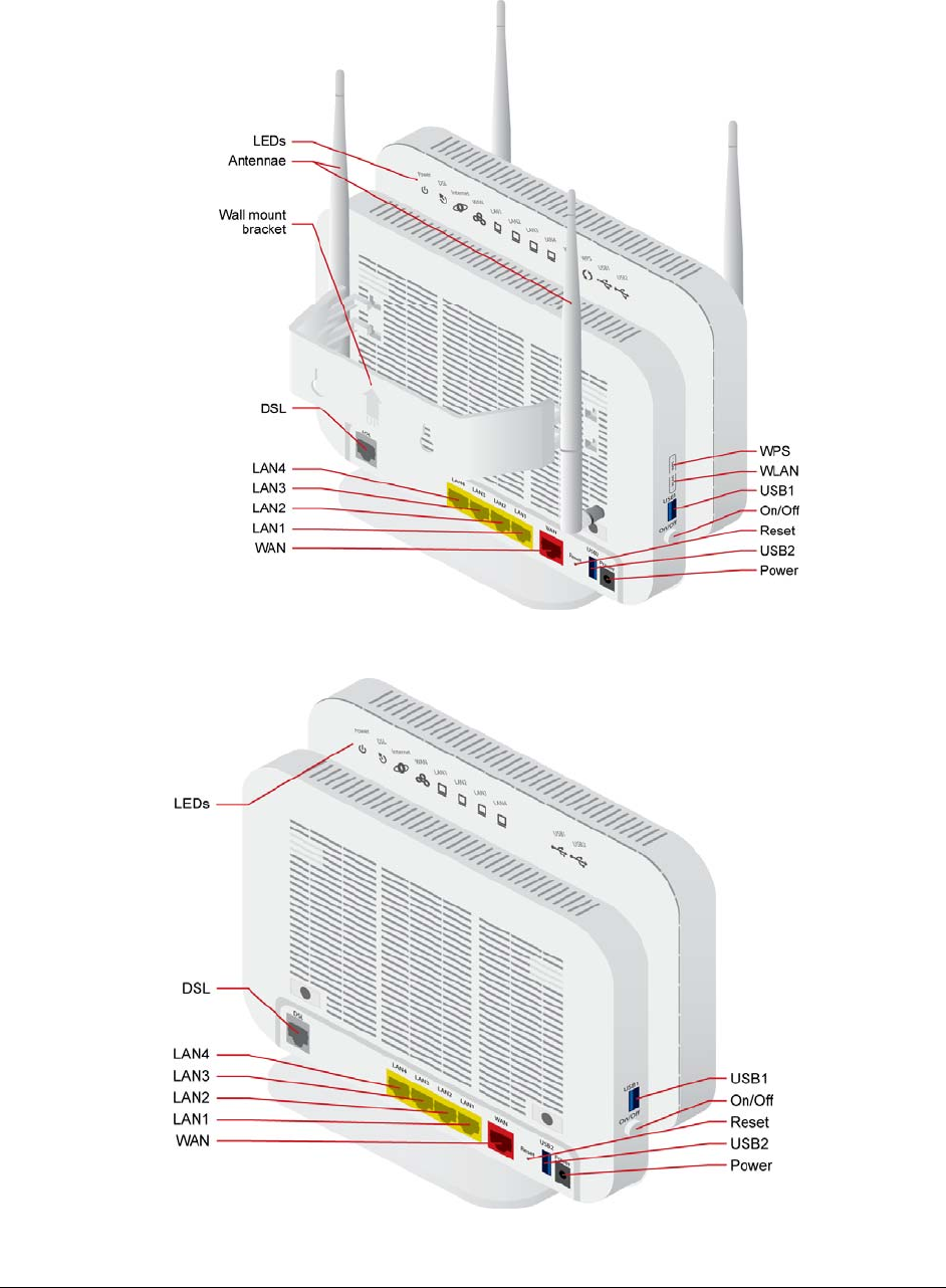
6712-W1 interfaces, LEDs and buttons
6718-W1 interfaces, LEDs and buttons
66xx/67xx Router Users Guide 21
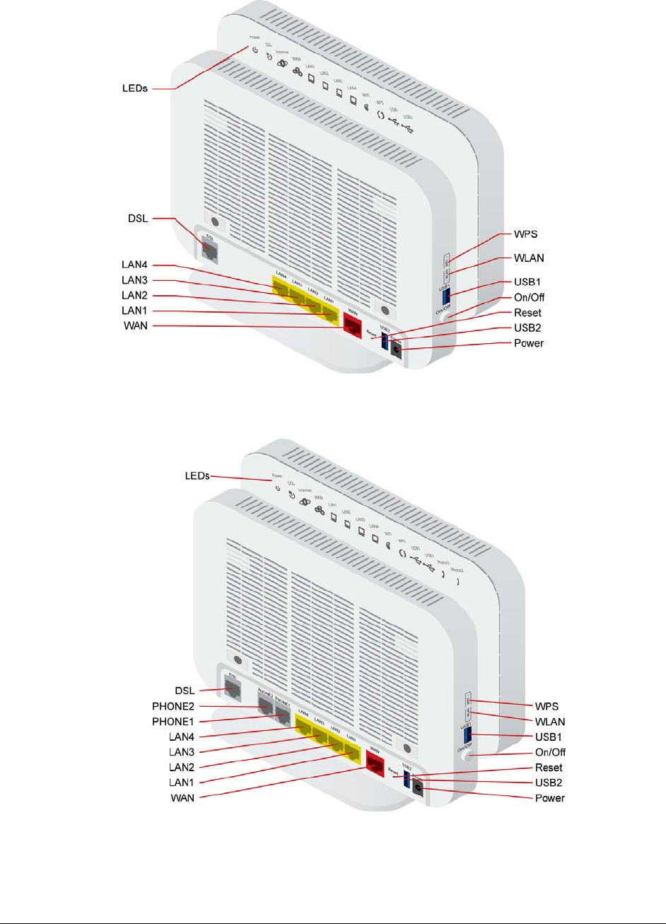
6728-W1 interfaces, LEDs and buttons
66xx/67xx Router Users Guide 22
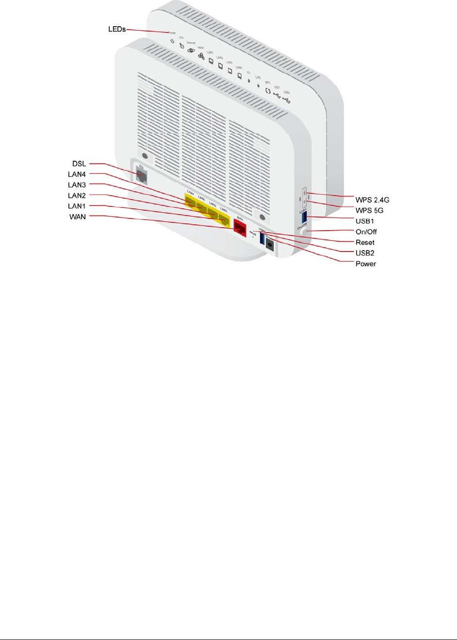
6729-W1 interfaces, LEDs and buttons
6732-W1 interfaces, LEDs and buttons
66xx/67xx Router Users Guide 23
6738-W1 interfaces, LEDs and buttons
6748-W1 interfaces, LEDs and buttons
66xx/67xx Router Users Guide 24
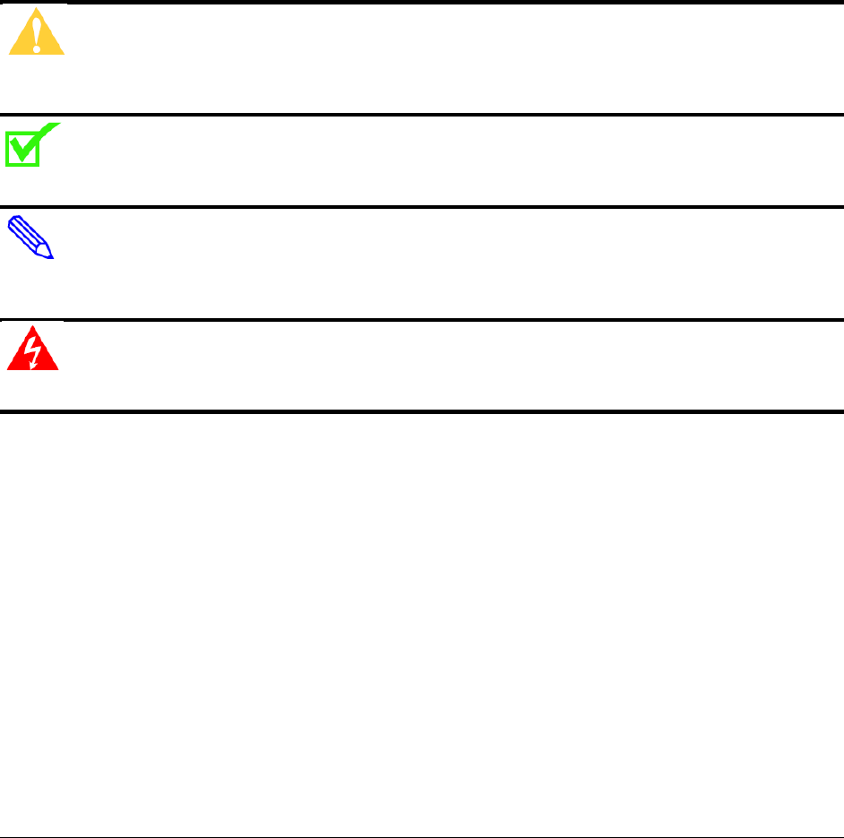
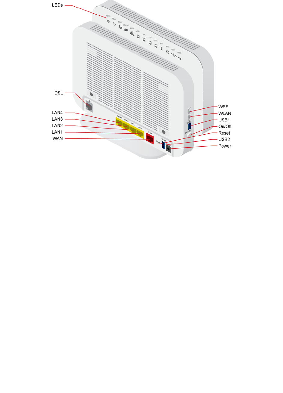
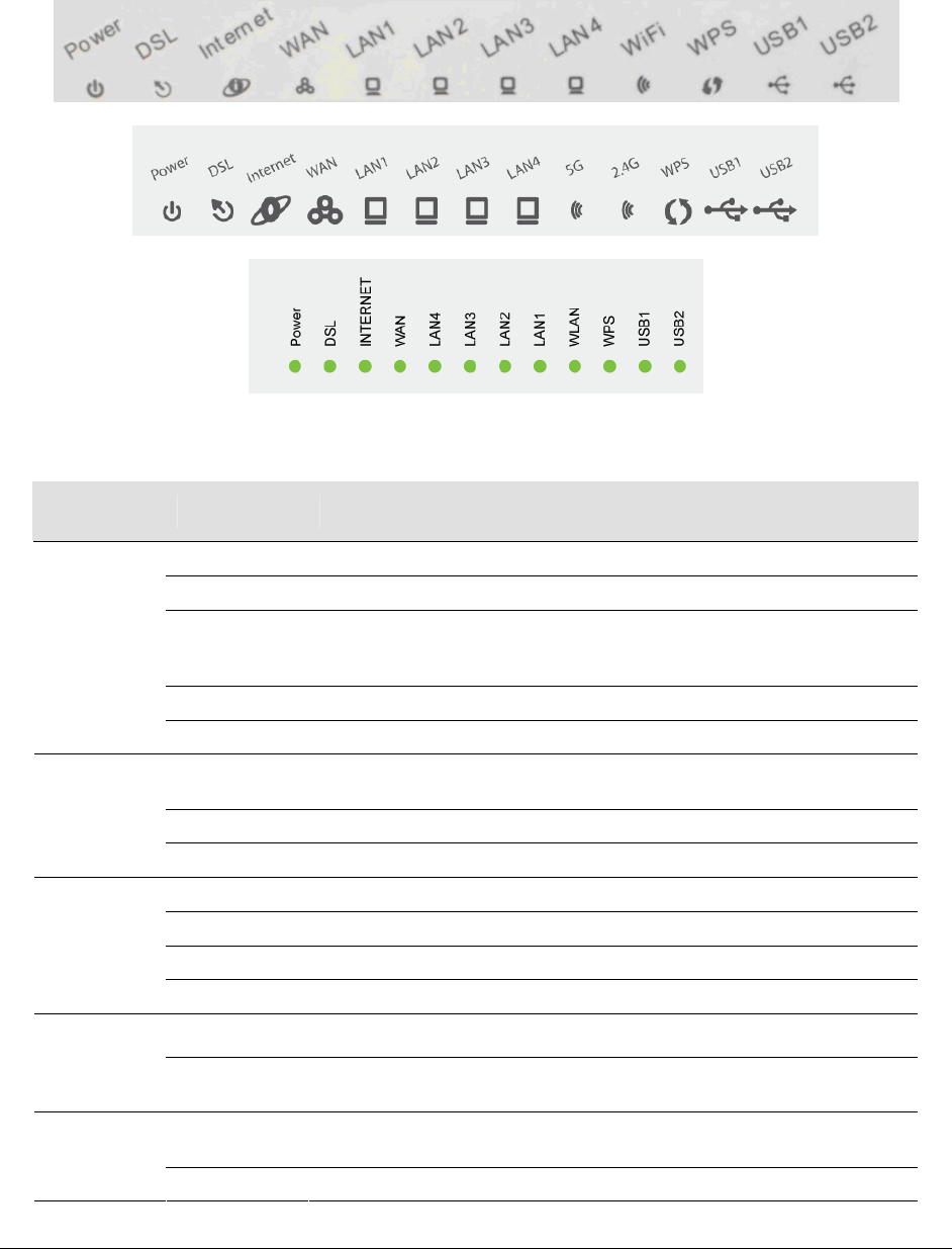
6768-W1 interfaces, LEDs and buttons
66xx/67xx Router Users Guide 25
Front Panel
Note: different models have different LEDs, however the LED behavior is the same.
LED Descriptions
LED Mode Description
Solid green The device is powered on and operating normally.
Blinking green The software is being upgraded.
Off The router may not be turned on. Check if the power adapter is
connected to the router, the router is plugged in and the power switch
button is in the on (pushed in) state.
Solid red Router is booting up.
Power
Blinking red The software is being upgraded.
Solid green Connection established. The router is able to communicate with your ISP
via DSL.
Blinking DSL line is training.
DSL
(DSL1 and
DSL 2 on
bonded units) Off Device is powered off.
Solid green Device is connected to the internet in routing mode.
Blinking green Internet data is being transmitted.
Off Ethernet interface is disconnected.
Internet
Solid red Authentication has failed.
Solid green The Ethernet WAN interface is connected.
WAN
Blinking green The device is sending or receiving data over the Ethernet WAN interface.
Solid green Ethernet interface is successfully connected to a device through the LAN
port.
LAN 1-4
Blinking green The device is sending or receiving data over Ethernet.

66xx/67xx Router Users Guide 26
LED Mode Description
Off Ethernet interface is disconnected.
Solid green Wireless is enabled.
Blinking green Wireless traffic activity.
WiFi
Off Wireless is disabled.
Solid green Connection has been established using the Wi-Fi Protected Setup.
Blinking green Connection is being negotiated using the Wi-Fi Protected Setup.
WPS
Off Wi-Fi Protected Setup disabled.
Solid green 2.4GHz wireless is enabled.
Blinking green 2.4GHz wireless traffic activity.
2.4G
(802.11b/g/n)
Off 2.4GHz wireless is disabled.
Solid green 5GHz wireless is enabled.
Blinking green 5GHz wireless traffic activity.
5GHz
(802.11ac)
Off 5GHz wireless is disabled.
Solid green A connection to a 3G or USB flash disk has established.
Blinking green Data is being transmitted.
USB 1-2
Off No signal detected.
Solid green The phone port is configured
Phone 1-2 Off The phone port is not configured
66xx/67xx Router Users Guide 27
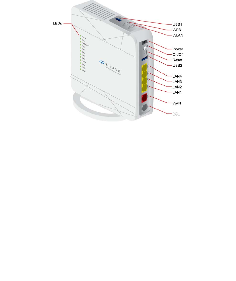
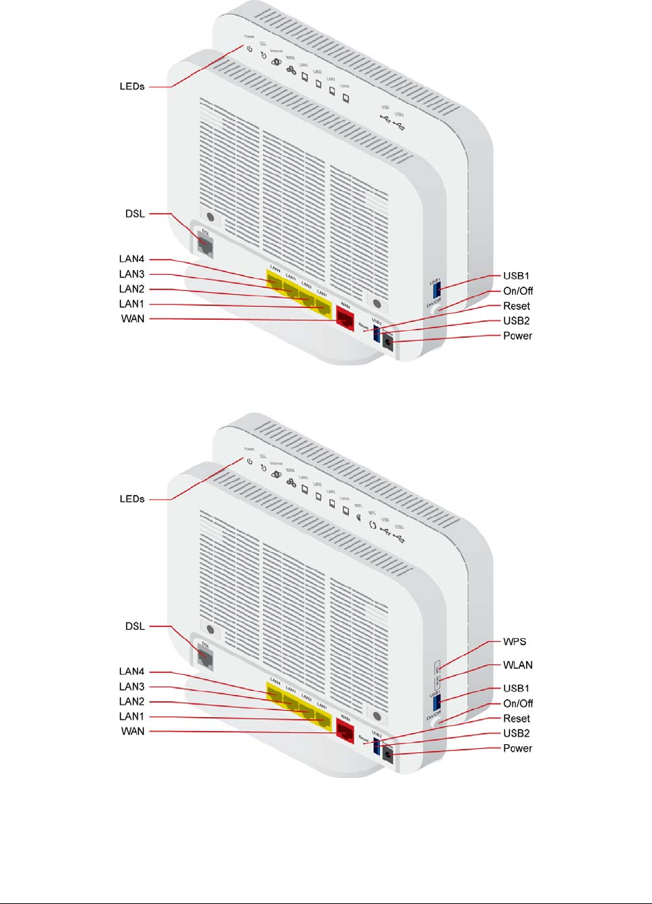
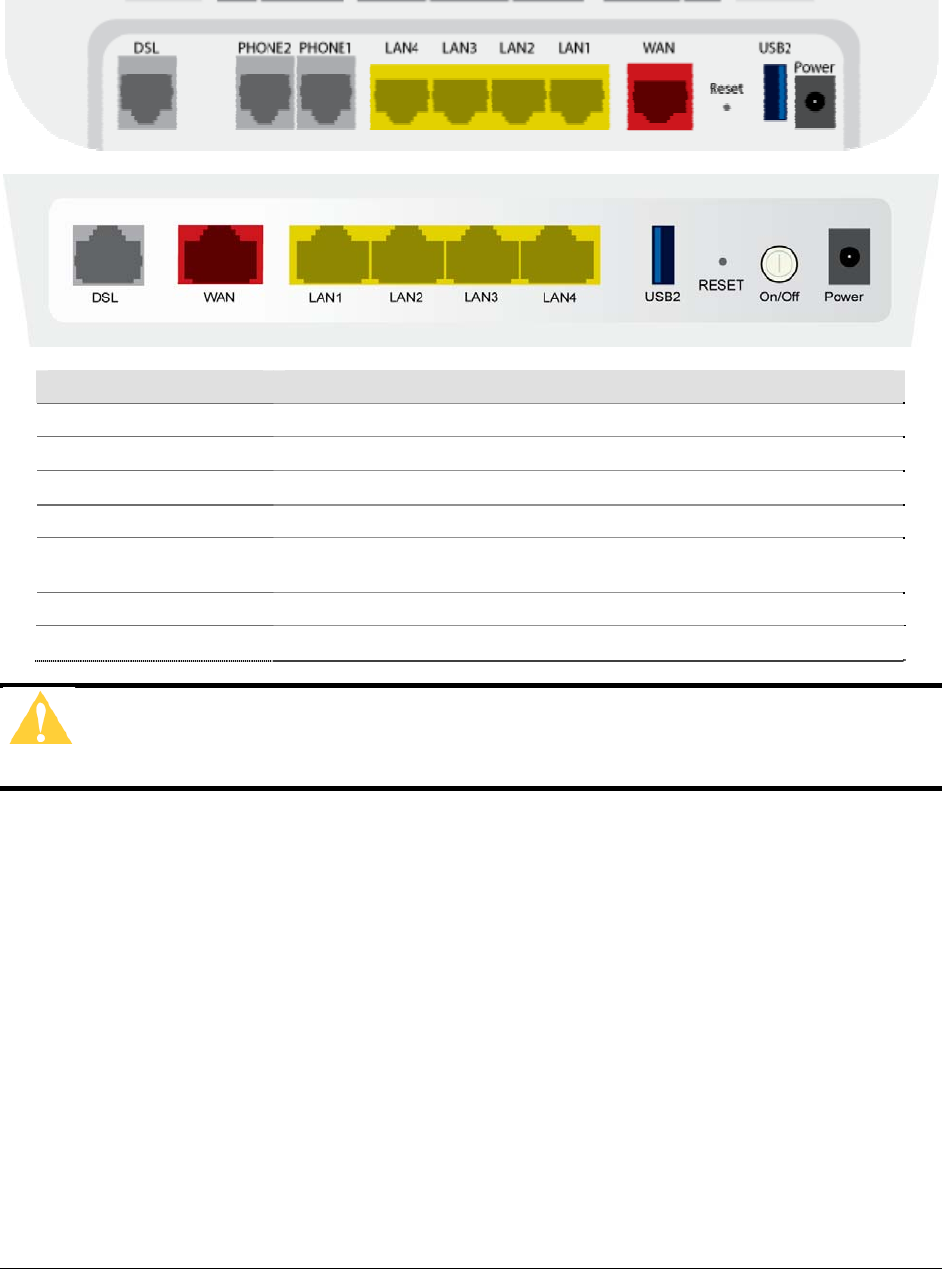
Back Panel
Port Description
DSL RJ-11 cable connects to incoming DSL line
LAN1 – LAN4 RJ-45 connects the unit to an Ethernet device such as a PC or a switch.
PHONE1 – PHONE 2 RJ-11 FXO port. Connect the gateway to a PSTN line with telephone cable.
WAN For connecting Ethernet cable to provide an Ethernet uplink.
Reset / Default Restores the factory default settings. Press the button for at least 1 second
and then release it. The router will reboot and return to its default settings.
USB 2 USB port, for connecting the 3G network card.
Power Connects to a power adapter. See table in Package Contents, page 17
Caution: Do not press the Reset button unless you want to clear the current
settings.
66xx/67xx Router Users Guide 28
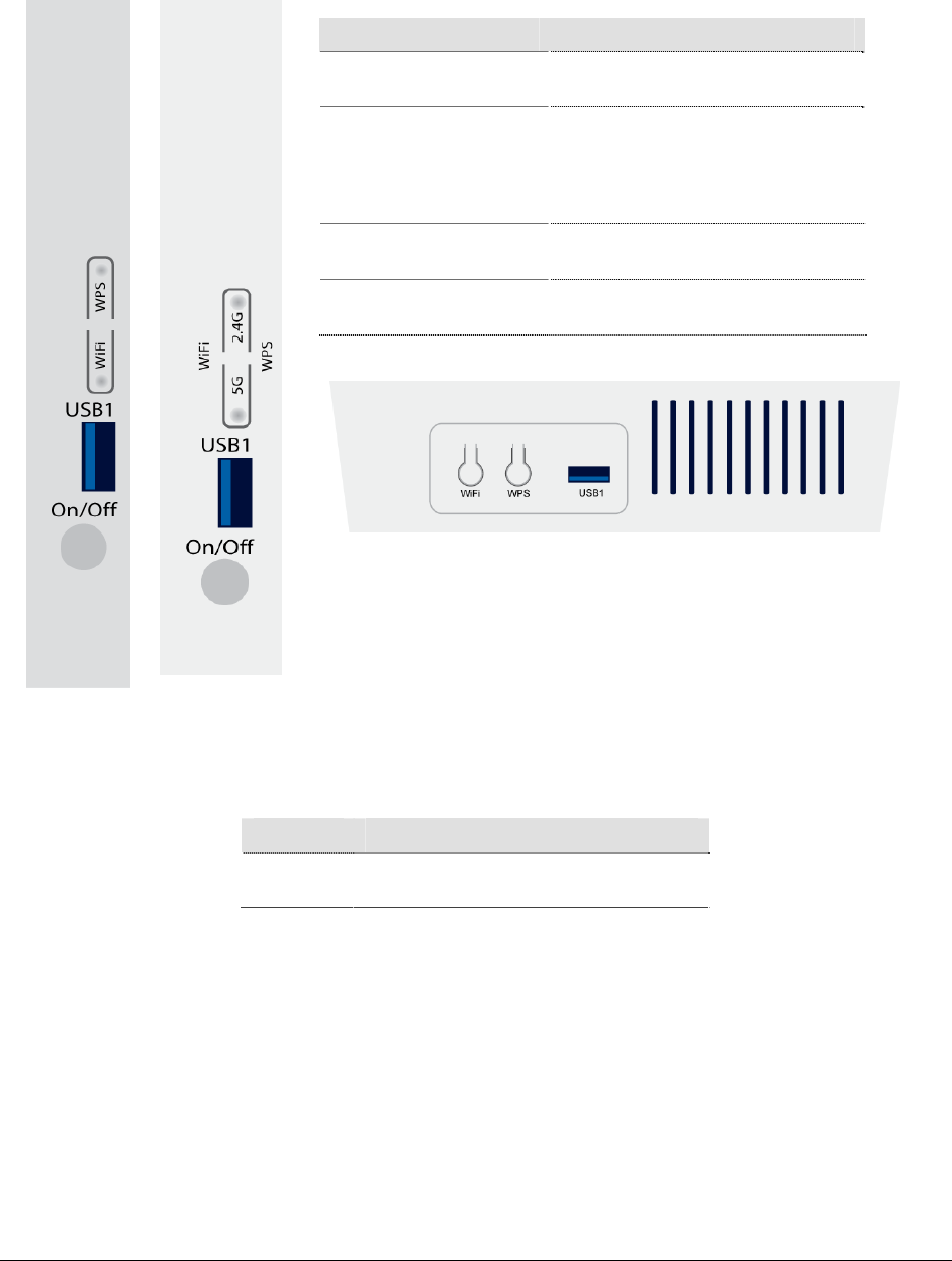
Side Panel
Unit Dimensions
Model Unit Dimensions
6xxx-W1 6.81" (17.30 cm) High x 6.44" (16.36 cm)
Wide x 2.44" (6.20 cm) Deep
Port Description
WiFi WLAN switch, for enabling or
disabling the WLAN function.
WPS
Enables WPS Push Button Connect
(PBC) mode. If WPS is enabled,
press this button, and then the
wireless router starts the negotiation
of PBC mode.
USB1 USB port, for connecting USB
storage devices.
On/Off Power on (depressed) or power off
for the router.
66xx/67xx Router Users Guide 29
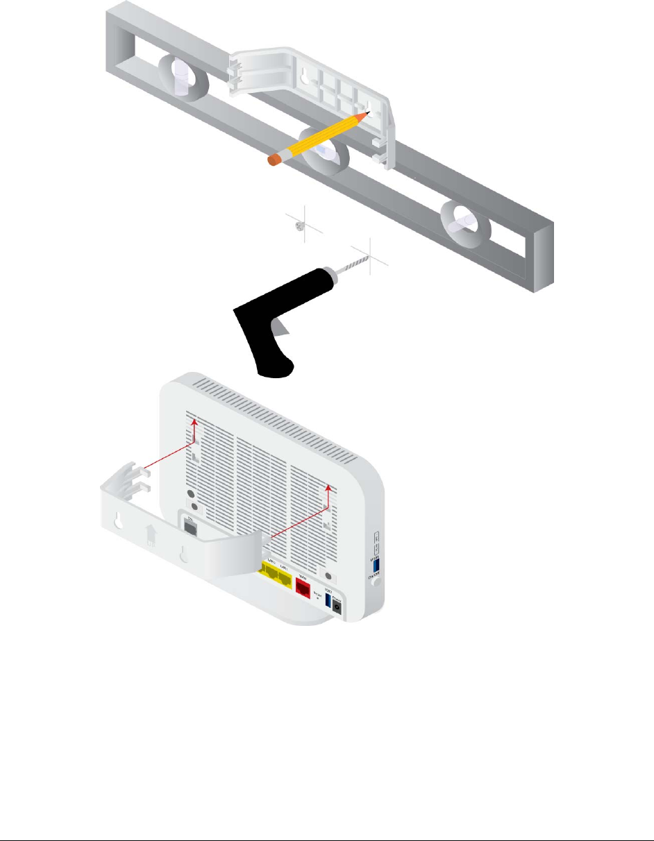
Wall Mount
Newer 6xxx units may be wall mounted with the wall mounting bracket that comes with
the unit.

66xx/67xx Router Users Guide 30
Chapter 2 Hardware Installation and PC Setup
Overview
This chapter provides basic instructions for connecting the gateway to a computer or a
LAN, a telephone, and to the Internet using the WAN interface. The first part provides
instructions to set up the hardware, and the second part describes how to prepare your
PC for use with the gateway. Refer to Chapter 3, The Web User Interface on page 35 for
configuration instructions.
It is assumed that you have already subscribed to WAN service with your telephone
company or other Internet service provider (ISP).
Connecting Your Hardware
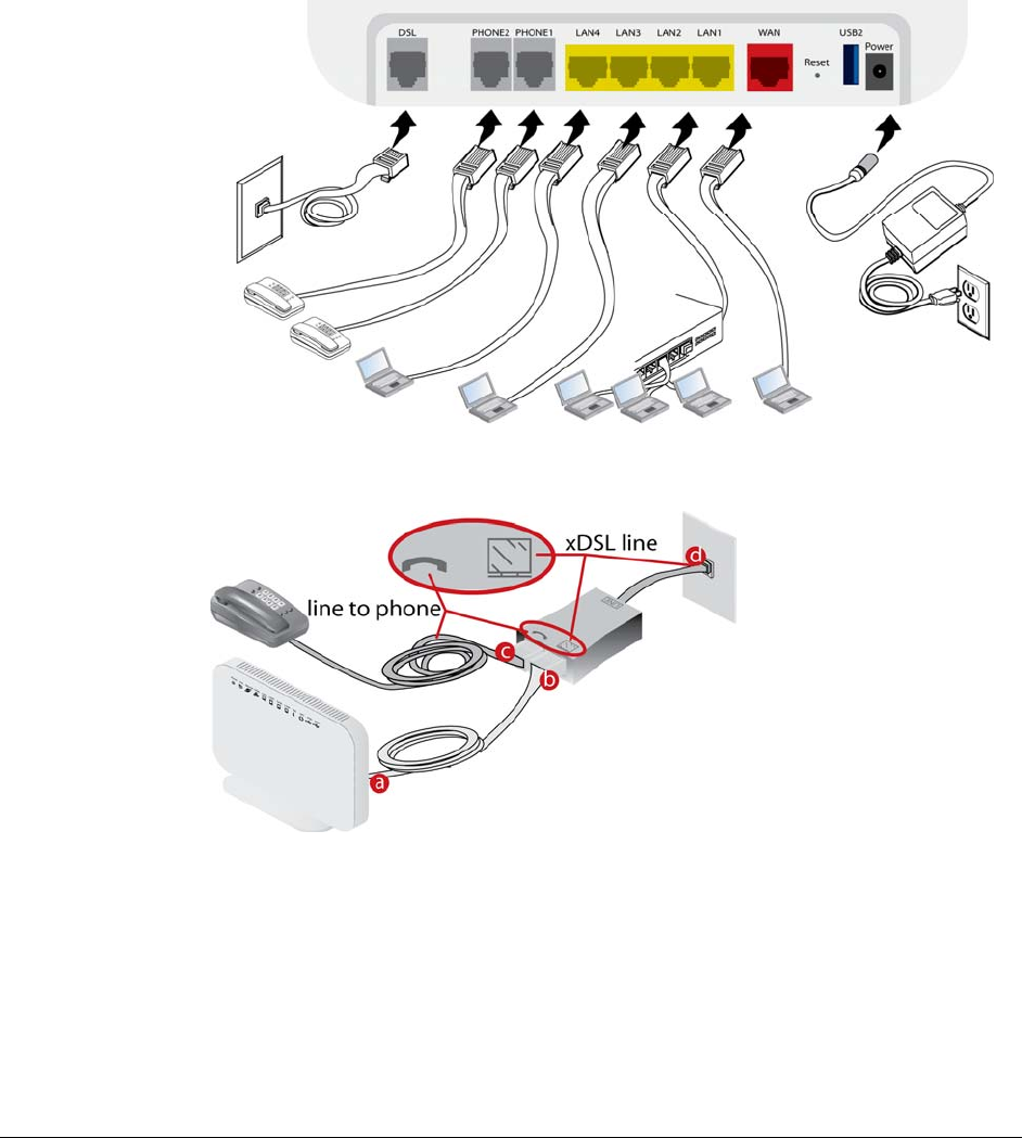
Shut down your PC before connecting the gateway. To connect the gateway:
1. Connect the WAN interface:
The 6xxx-W1 devices support different WAN interfaces: DSL or Ethernet.
Note: Only one WAN interface can be active at a time.
2. Connect the PC to the gateway
To use the Ethernet connection, connect the Ethernet cable from the computer
directly to one of the four ports labelled LAN on the back of the gateway.
66xx/67xx Router Users Guide 31
3. Connect the power adapter
Complete the process by connecting the AC power adapter to the Power connector
on the back of the device and plug the adapter into a wall outlet or power strip. Then
turn on and boot up your PC and any LAN devices, such as hubs or switches, and
any computers connected to them.
For single line gateways (non bonded xDSL)
Complete the process by connecting the AC power adapter to the Power connector
on the back of the device and plug the adapter into a wall outlet or power strip. Then
turn on and boot up your PC and any LAN devices, such as hubs or switches, and
any computers connected to them.
For situations where a phone is also used:
66xx/67xx Router Users Guide 32
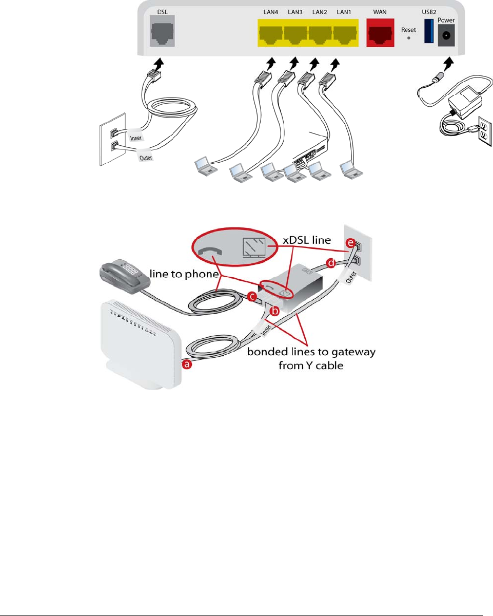
For bonded gateways (6728-W1):
The 6728-W1 can be configured for single or bonded line operation. A Y–cable is
provided. Use both the wire pairs marked “Inner” and “Outer” connected to two
network interface outlets for bonded operation. For single line operation, use only
the wire marked “Outer.”
For bonded situations where a phone is also used:

66xx/67xx Router Users Guide 33
Configuring Your Computer
Prior to accessing the gateway through the LAN or the USB port, note the following
necessary configurations:
Your PC’s TCP/IP address: 192.168.1.__( the last number is any number between 2 and
254)
The gateway’s default IP address: 192.168.1.1
Subnet mask: 255.255.255.0
Below are the procedures for configuring your computer. Follow the instructions for the
operating system that you are using.
If you used the Ethernet cable to connect your gateway and PC, you do not need any
specific driver installation.
Windows 2000
1. In the Windows taskbar, click the Start button and point to Settings, Control Panel,
and Network and Dial-up Connections (in that order).
2. Click Local Area Connection. When you have the Local Area Connection Status
window open, click Properties.
3. Listed in the window are the installed network components. If the list includes
Internet Protocol (TCP/IP), then the protocol has already been enabled, and you
can skip to Step 9.
4. If Internet Protocol (TCP/IP) does not appear as an installed component, then click
Install.
5. In the Select Network Component Type window, click on protocol and then the
Add button.
6. Select Internet Protocol (TCP/IP) from the list and then click on OK.
7. If prompted to restart your computer with the new settings, click OK.
8. After your computer restarts, click the Network and Dial-up Connections icon
again, and right click on the Local Area Connection icon and then select
Properties.
9. In the Local Area Connection Properties dialog box, select Internet Protocol
(TCP/IP) and then click Properties.
10. In the Internet Protocol (TCP/IP) Properties dialog box, click the radio button
labelled Use the following IP address and type 192.168.1.x (where x is any
number between 2 and 254) and 255.255.255.0 in the IP address field and Subnet
Mask field.
11. Click OK twice to save your changes and then close the Control Panel.

66xx/67xx Router Users Guide 34
Windows XP
1. In the Windows taskbar, click the Start button and point to Settings and then click
Network Connections.
2. In the Network Connections window, right click on the Local Area Connection
icon and click on Properties.
3. Listed in the Local Area Connection window are the installed network components.
Make sure the box for Internet Protocol (TCP/IP) is checked and then click
Properties.
4. In the Internet Protocol (TCP/IP) Properties dialog box, click the radio button
labelled Use the following IP address and type 192.168.1.x (where x is any
number between 2 and 254) and 255.255.255.0 in the IP address field and Subnet
Mask field.
5. Click OK twice to save your changes and then close the Control Panel.
Windows 7
1. In the Windows taskbar, click the Start button and point to Control Panel and then
click Network and Internet.
2. In the Network and Internet window, click Network and Sharing Center.
3. In the left panel click Change adapter settings.
4. In the Network Connections screen, right click Local Area Connection and select
Properties.
5. Listed in the Local Area Connection window are the installed network components.
Select Internet Protocol Version 4 (TCP/IP v4) is checked and then click
Properties.
6. In the Internet Protocol Version 4 (TCP/IP v4) dialog box, click the radio button
labelled Use the following IP address and type 192.168.1.x (where x is any
number between 2 and 254) and 255.255.255.0 in the IP address field and Subnet
Mask field.
7. Click OK the Close to save your changes and then close the Control Panel.
66xx/67xx Router Users Guide 35
Chapter 3 The Web User Interface
The 6xxx gateways have a Wide Area Network (WAN) connection which connects to your
Internet Service Provider (ISP) via a DSL, Ethernet interface, or a 3G connection. The Local Area
Network (LAN) connections are where you plug in your local computers to the gateway. The 6xxx
also has a wireless interface. The gateway is normally configured to automatically provide all the
PCs on your network with Internet addresses.
Your gateway may be pre-configured with your ISP configuration to ease your installation.
Please contact your ISP if you need information on how to connect the gateway to your ISP. To
set up your gateway with a basic configuration required by your service provider, you can use the
Quick Setup form the top of the navigation bar. In order for this to work, all other WAN services
must first be removed. To remove services, from the top navigation bar select Quick Setup.
If you connected a PC (rather than a hub or a switch) directly to the gateway, your LAN consists
of that PC. You may also create connections for various protocol options by creating new
connections.
To configure your device you will first need to log in to the gateway.
Note: Before configuring your gateway, make sure you have followed the instructions in Chapter
2, Hardware Installation and PC Setup on page 30. You should have your PCs configured for
DHCP mode (if your gateway will be), and have proxies disabled on your browser. If you see a
login redirection screen when you access the web interface, verify that JavaScript support is
enabled in your browser. Also, if you do not get the screen shown below, you may need to delete
your temporary Internet files.
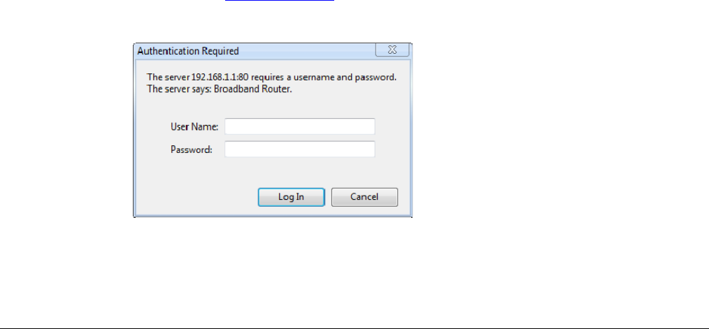
Log in to the Gateway
This section explains how to log in to your gateway.
1. Launch your web browser.
2. Enter the URL http://192.168.1.1 in the address bar and press Enter.
A login screen like the one below will be displayed after you connect to the user interface.
3. Enter your user name and password, and then click on OK to display the user interface.
The default admin user name / password is admin / adminXXXXXX, where XXXXXX is the
last six digits of the serial number of the unit; both user name and password are case
sensitive.
66xx/67xx Router Users Guide 36
Note: For security reasons you should change your password as soon as possible.
Note: There are three default user name and password combinations; admin, support, and user.
The user / user name and password combination provides limited access to the gateway. With
this password you can view the configuration, run diagnostics, and change the LAN side
configuration such as the WiFi, but you cannot change the WAN configuration.
The support/supportXXXXXX combination allows an ISP technician to access the gateway from
the WAN only to perform maintenance and run diagnostics. The XXXXXX are the last six
digits of the serial number of the unit.
The admin / adminXXXXXX combination can perform all functions.
All passwords are case sensitive and can be changed at any time. For information about password
administration, see Passwords on page 165.
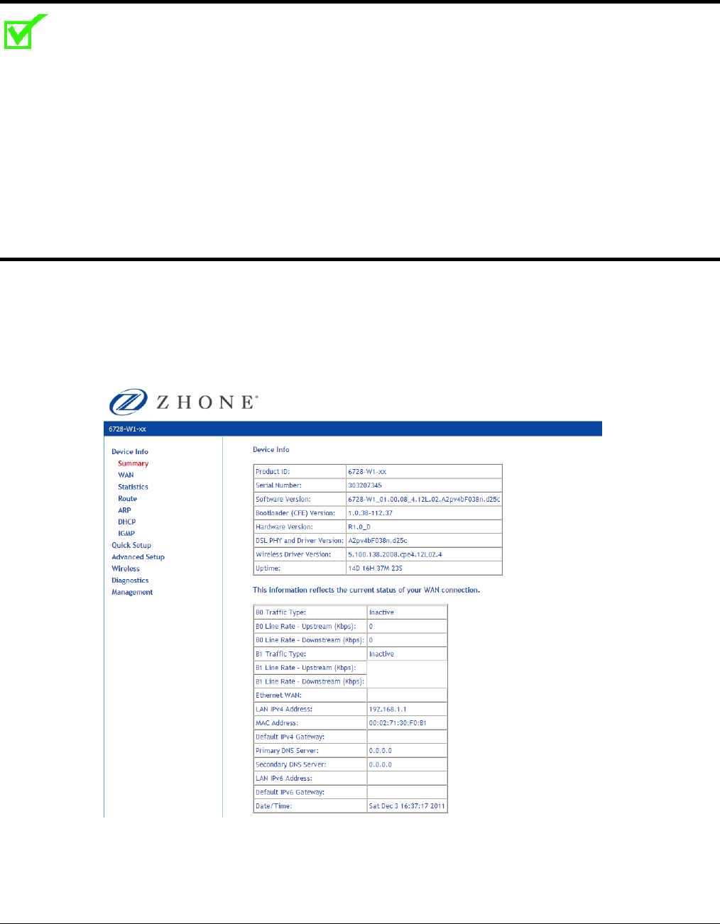
Summary
Access the general information of the gateway by clicking Summary under Device Info. This
screen shows details of the gateway such as the version of the software, bootloader, LAN IP
address, etc. It also displays the current status of your WAN connection as shown below.
66xx/67xx Router Users Guide 37
WAN Information
Display the WAN status report from the gateway by clicking WAN under Device Info. The graphic
below shows the screen when a WAN connection is set up.
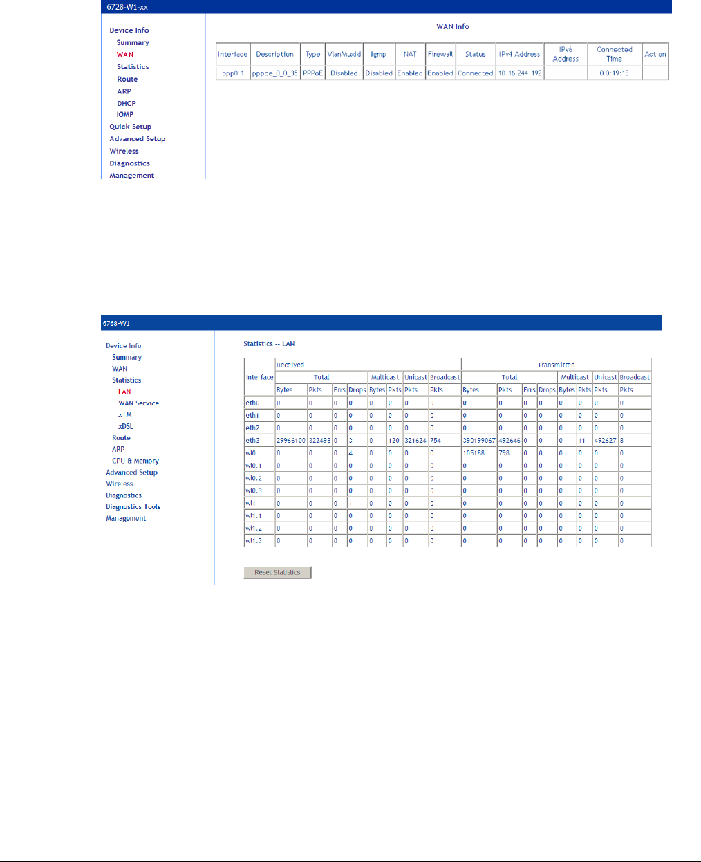
Statistics
LAN Statistics
Display LAN statistics by clicking LAN under Statistics
66xx/67xx Router Users Guide 38
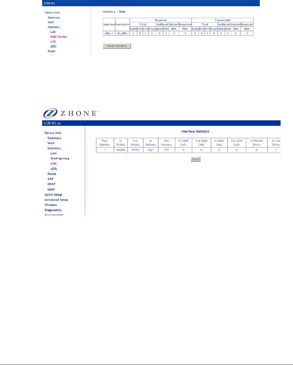
WAN Statistics
Display WAN statistics by clicking WAN Service under Statistics.
xTM Statistics
Display ATM statistics by clicking xTM under Statistics.
66xx/67xx Router Users Guide 39
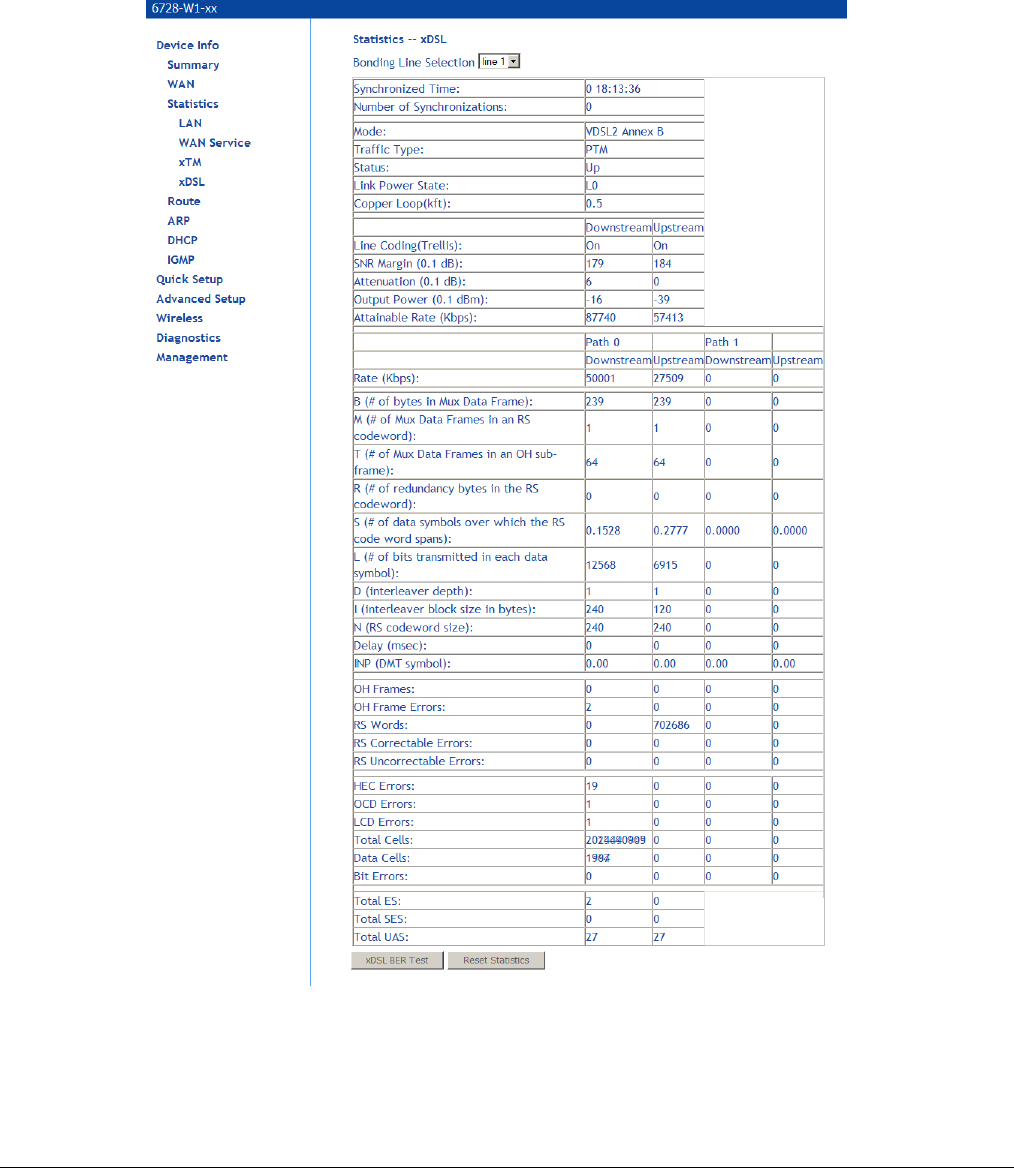
xDSL Statistics
Display VDSL statistics by clicking xDSL under Statistics. Information contained in this screen is
useful for troubleshooting and diagnostics of connection problems.
To view the statistics for one of the bonding lines, select the line from the Bonding Line
Selection dropdown.
66xx/67xx Router Users Guide 40
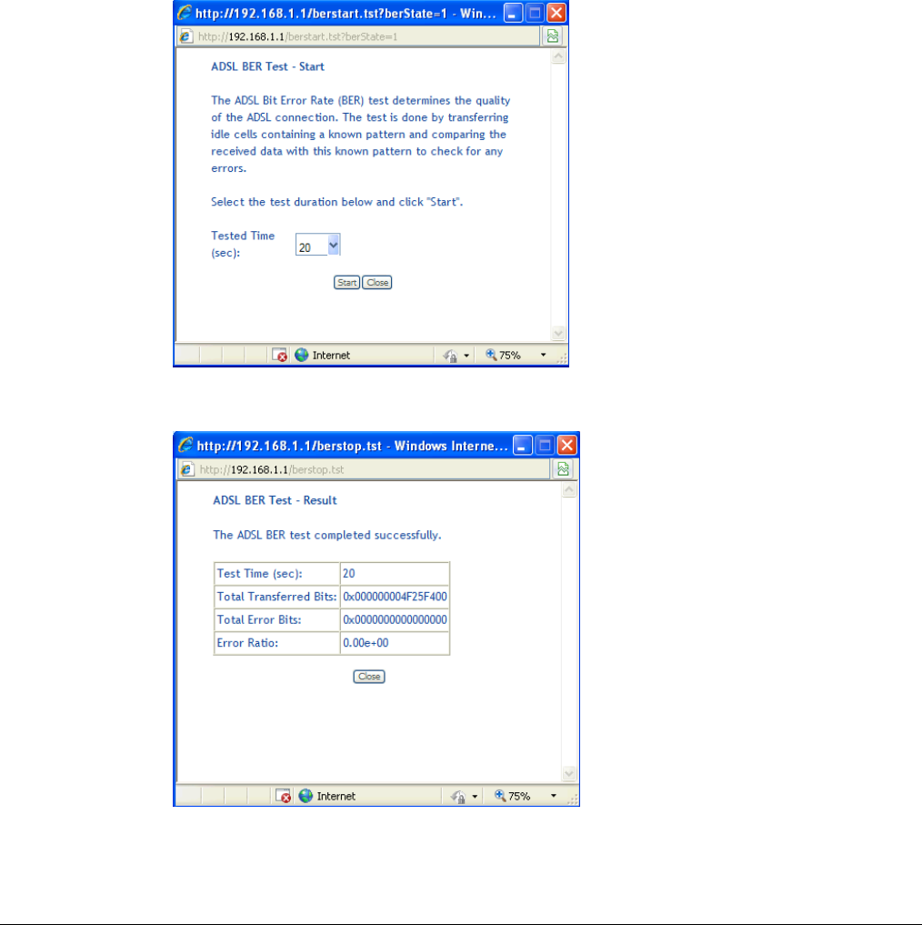
xDSL BER Test
The xDSL Bit Error Rate (BER) test determines the quality of the VDSL connection. The test is
performed by transferring idle cells containing a known pattern and comparing the received data
with this known pattern to check for any errors The BER Test reflects the ratio of error bits to the
total number transmitted.
To run a BER test:
1. On the bottom of the xDSL statistics page, click xDSL BER Test
2. In the xDSL BER Test – Start screen select the duration of the test from the Tested Time
(sec) drop down, then click Start.
3. Check the results.
66xx/67xx Router Users Guide 41
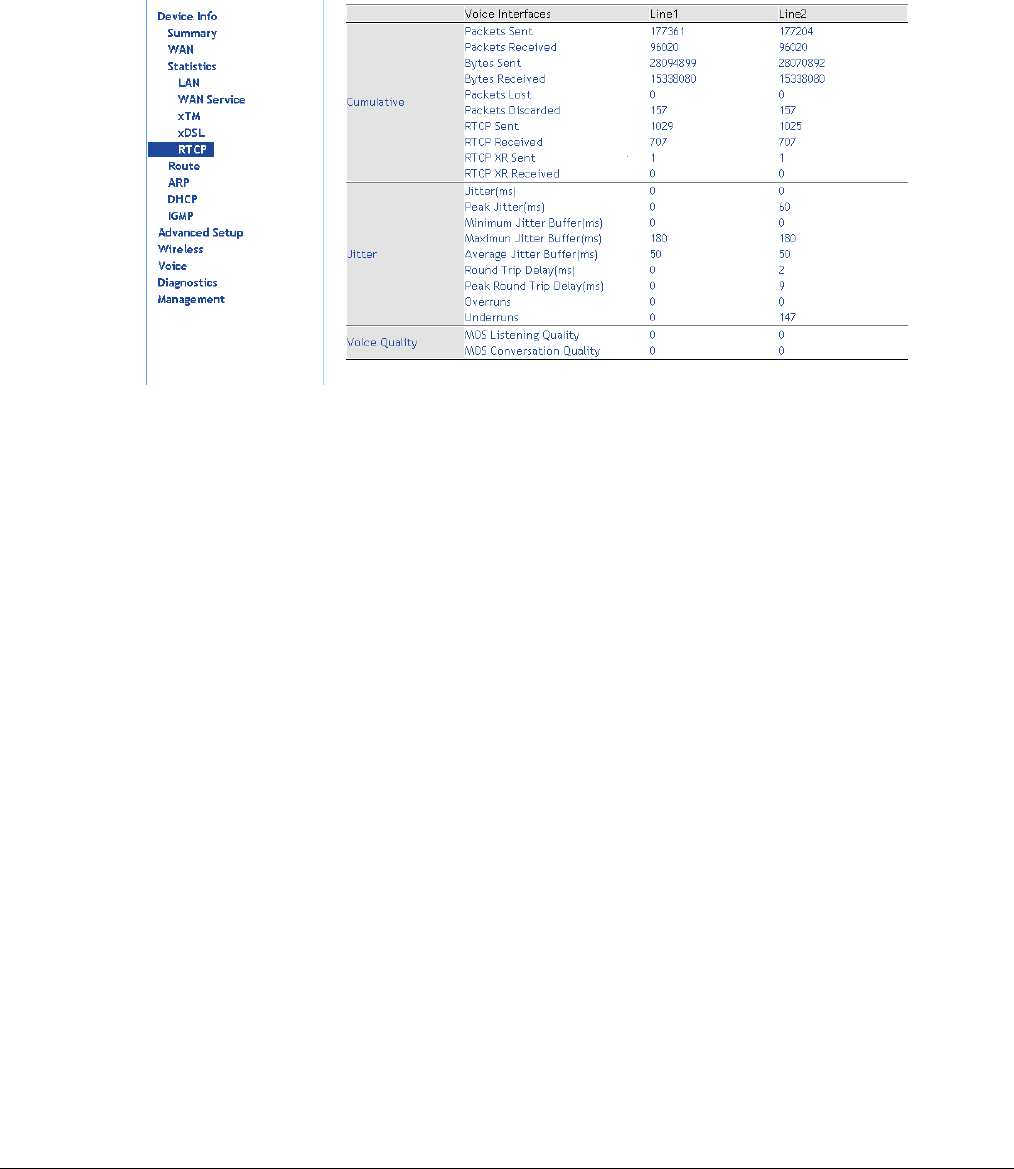
RTCP
Real-Time Packet Protocol (RTP) statistics can be used to determine activity sent into the
network or received from the network on the VoIP lines. RTP is used with Real-time Control
Protocol (RTCP) which monitors transmission statistics through control packets sent into or
received from the network.
Cumulative statistics are kept across calls
Packets Sent: The cumulative count of data bytes in the packets sent to the network
Bytes Sent: The cumulative count of data bytes in the packets sent to the network
Bytes Received: The cumulative count of data bytes in the packets received from the network
Packets Lost: The number of packets not received based upon sequence numbers
Packets Discarded: The number of packets received but discarded
RTCP Sent: The number of control packets sent into the network
RTCP Received: The number of control packets received from the network
RTCP XR Sent: The number of extended reporting control packets sent into the network (should be
the same as RTCP Sent)
RTCP XR Received: The number of extended reporting control packets received from the network
Jitter statistics are kept from the previous call
Jitter (ms): The average delay variation (Jitter) between RTP packets
Peak Jitter (ms): The peak delay variation (Jitter) between RTP packets
Minimum Jitter Buffer (ms): The least delay an RTP packet had passing through the Jitter buffer
Maximum Jitter Buffer (ms): The greatest delay an RTP packet had passing through the Jitter
buffer
Average Jitter Buffer (ms): The average delay an RTP packet had passing through the Jitter
buffer
Round Trip Delay (ms): The two way network delay
Peak Round Trip Delay (ms): The worst two way network delay
Overruns: Number of packets received that could not be sent to the Jitter buffer since it was full
Underruns: The number of times the Jitter buffer was empty
66xx/67xx Router Users Guide 42
Voice Quality statistics are kept from the previous call
MOS Listening Quality: Mean Opinion Score. On a scale from 0 (poor) to 5 (good)
MOS Conversation Quality: Mean Opinion Score. On a scale from 0 (poor) to 5 (good)
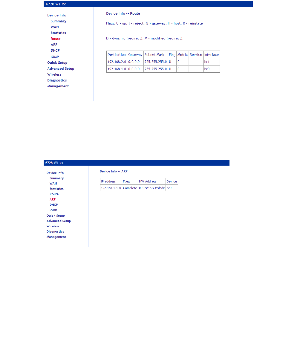
Route Table
Access the routing status report from the gateway by clicking Route under Device Info.
ARP Table
Display the ARP status report by clicking ARP under Device Info.
ARP (Address Resolution Protocol) maps the IP address to the physical address, labelled HW
Address (the MAC address) and identifies computers on the LAN.
66xx/67xx Router Users Guide 43
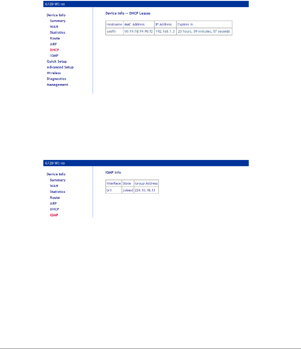
DHCP Table
Display the DHCP lease information by clicking DHCP under Device Info.
DHCP (Dynamic Host Control Protocol) allows the modem to automatically assign IP addresses,
to connected devices. By default, your modem gateway set up to assign devices addresses from
192.168.1.2 to 192.168.1.254.
IGMP
Display the IGMP stream information by clicking IGMP under Device Info.
IGMP (Internet Group Management Protocol) is used to create group memberships for multicast
streams. Normally IGMP is used for streaming video and other applications such as gaming, to
provide more efficient use of the network resources for these types of applications.
66xx/67xx Router Users Guide 44
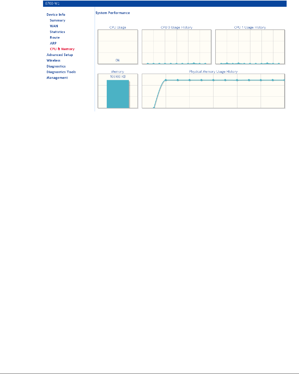
System Performance
Graphically displays the CPU and memory performance of the device.
66xx/67xx Router Users Guide 45
Chapter 4 Quick Setup
The Automatic Configuration feature will automatically detect the first usable PVC and
automatically detect PPPoE, PPPoA, and Bridge Protocol (with DHCP Server available). To use
the Automatic Configuration feature, check the Automatic Configuration option.
Note: In order for the automatic configuration to work, all previously defined WAN configurations must
be removed.
Quick Setup with Automatic Configuration
To enable the Automatic Configuration feature:
1. From the navigation pane on the left select Quick Setup.
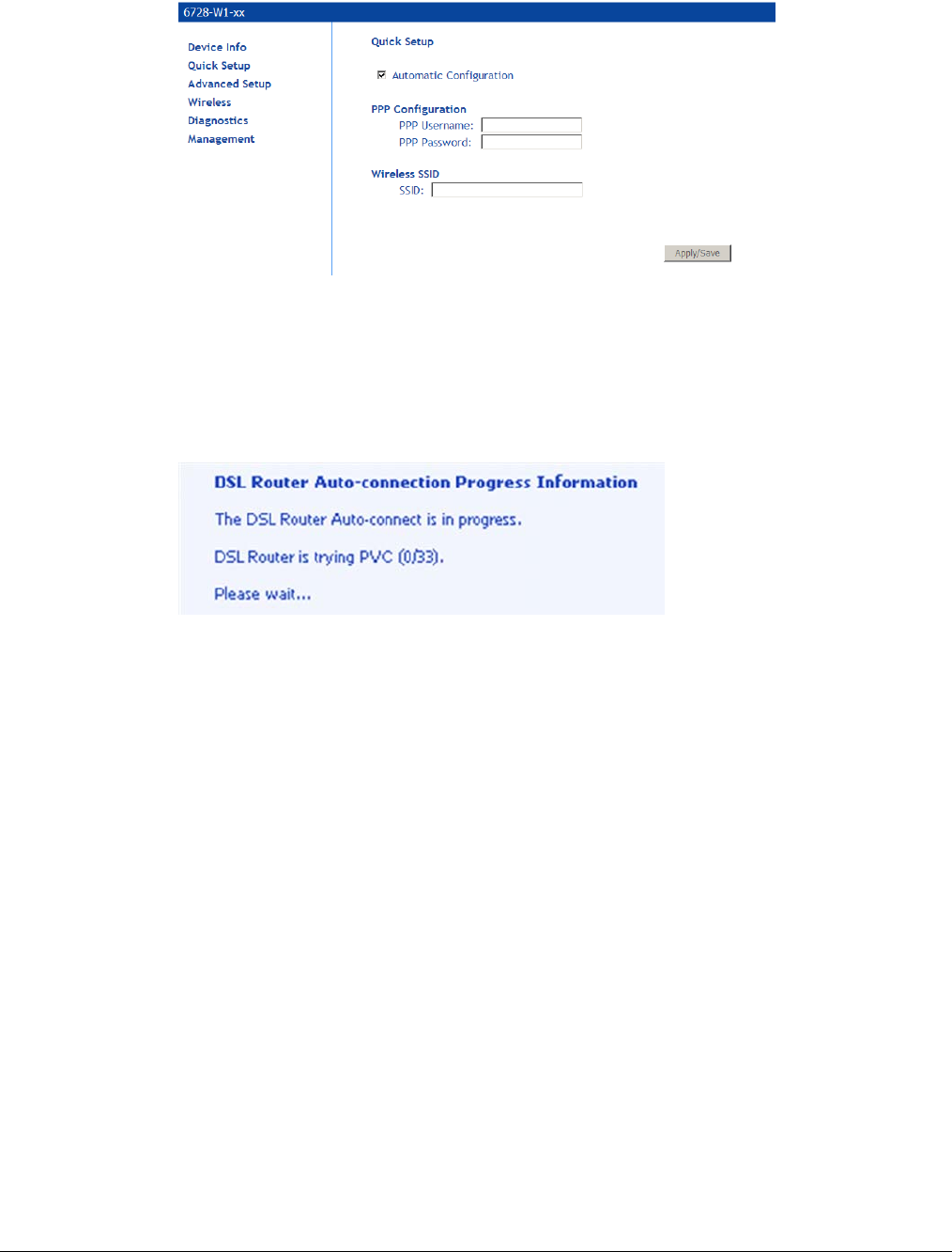
66xx/67xx Router Users Guide 46
2. Select Automatic Configuration.
3. Enter the SSID.
4. You will need to enter the PPP username and password as provided by your ISP.
5. Click Apply/Save.
You will see a progress screen:
When the connection is complete you will see the Service Setup summary screen.
66xx/67xx Router Users Guide 47
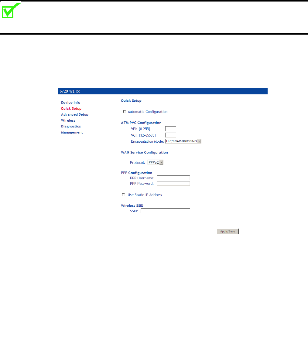
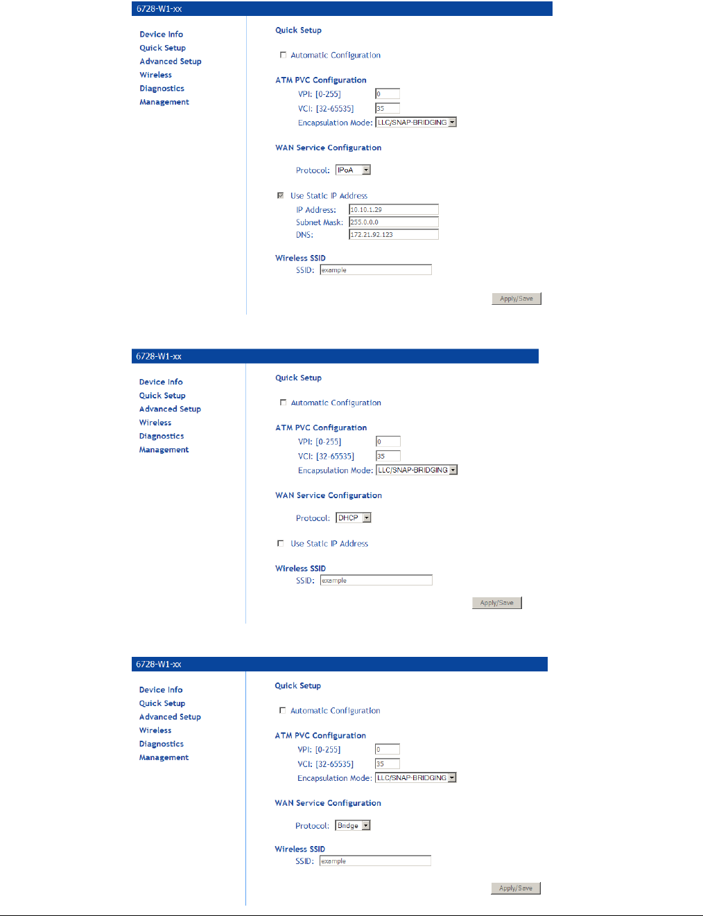
Quick Setup with Automatic Configuration Disabled
1. From the navigation pane on the left select Quick Setup.
2. Specify VPI and VCI as directed by your ISP.
3. Select the Encapsulation Mode as directed by your ISP.
4. Under WAN Service Configuration select the protocol for the WAN connection from the
Protocol dropdown as directed by your ISP.
Depending on the protocol selected further parameters are presented.
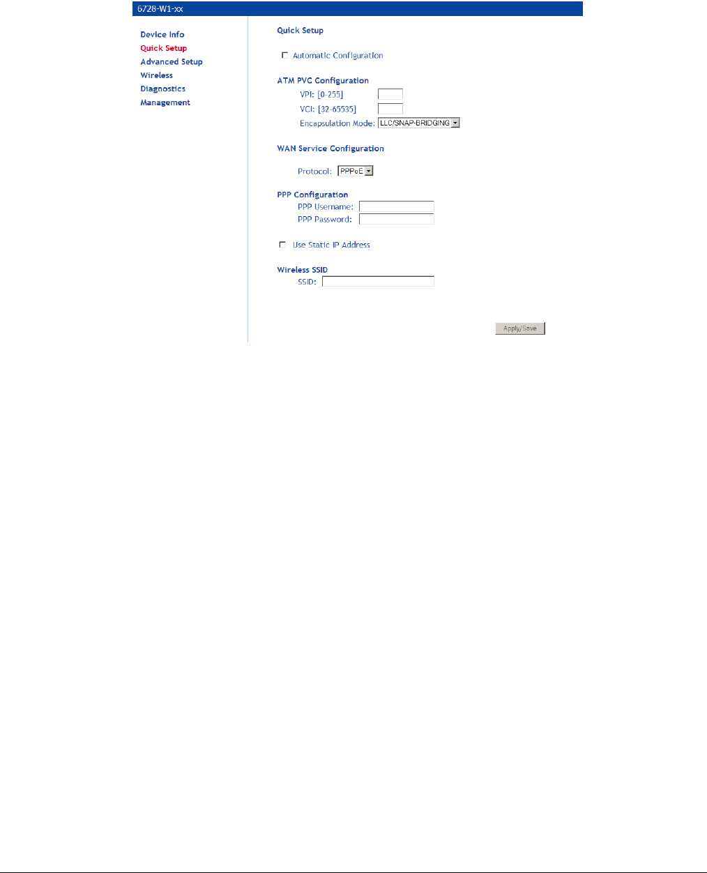
66xx/67xx Router Users Guide 48
PPPoE and PPPoA: You will need to enter the PPP username and password as provided
by your ISP.
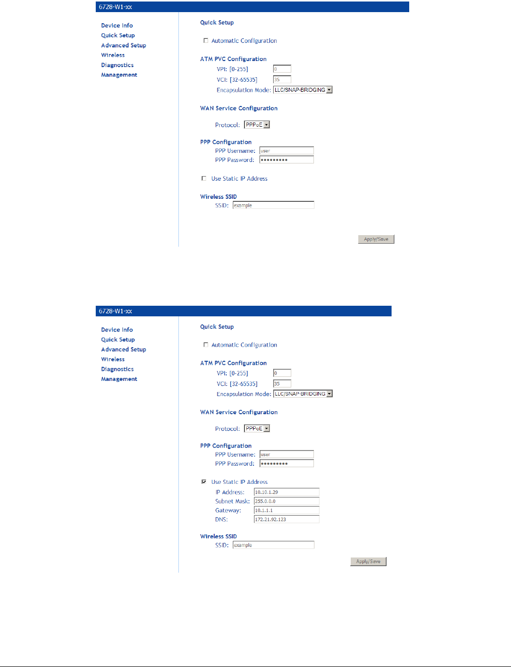
For PPPoE or DHCP, if desired, the DSL Gateway can be configured with a static IP
address and Subnet Mask for the LAN interface to correspond to your LAN’s IP Subnet. To
use a static IP address check the Use Static IP Address option, then enter the IP Address,
Subnet Mask, Default Gateway and DNS server.
66xx/67xx Router Users Guide 49
IPoA: For IPoA your ISP will supply information for IP Address, Subnet Mask, and DNS
server.
DHCP: With DHCP option you do not set any other options.
Bridge: With the Bridge option you do not set any other options.

66xx/67xx Router Users Guide 50
5. With Quick Setup the gateway’s wireless option is automatically set up and you will need to
enter the SSID.
The passkey is printed on the bottom of the unit. On the bottom of the unit there is a label which says,
“WPA Passphrase YYYYYYYYYYYY” where YYYYYYYYYYYY is the passkey for the Wireless SSID.
6. Click Apply/Save to save your settings.

66xx/67xx Router Users Guide 51
Chapter 5 Advanced Setup
This section contains advanced setup settings. To create a connection you need to define the
Layer 2 interface and the WAN service.
Configuration Types
VDSL is a PTM or ATM (ADSL fallback) based technology. The gateway supports Bridging and
Ethernet over ATM (EoA) configurations and ATM based configurations:
Bridging
Bridging (Layer 2 MAC addressing); uses Ethernet frames.
PPPoE
Point to Point Protocol over Ethernet; encapsulates PPP packet in Ethernet. (RFC 2516)
IPoE
IP over Ethernet (Layer 3 Internet Protocol addressing in Ethernet frames)
PPPoA
Point to Point Protocol over ATM, encapsulates PPP frames in ATM adaption layer 5 (AAL5)
packets.
IPoA
IP over ATM (Layer 3 Internet Protocol addressing in AAL5 packets
The table below describes the supported WAN interfaces and services supported on each interface.
WAN Interface Supported WAN Service
ATM Bridging
IPoA
IPoE/DHCP
PPPoA
PPPoE
PTM Bridging
IPoE/DHCP
PPPoE
Ethernet Bridging
IPoE/DHCP
PPPoE
To configure a connection, you first configure the connection type. EoA, PPPoA, or IPoA.
1. Add a Layer 2 interface and select the connection type.
EoA is used for PPPoE, IPoE and Bridge connections. PPPoA and IPoA are AAL5 based connections.
2. Set the WAN interface.
The WAN interface options to select are determined by the Layer 2 interface type.
66xx/67xx Router Users Guide 52
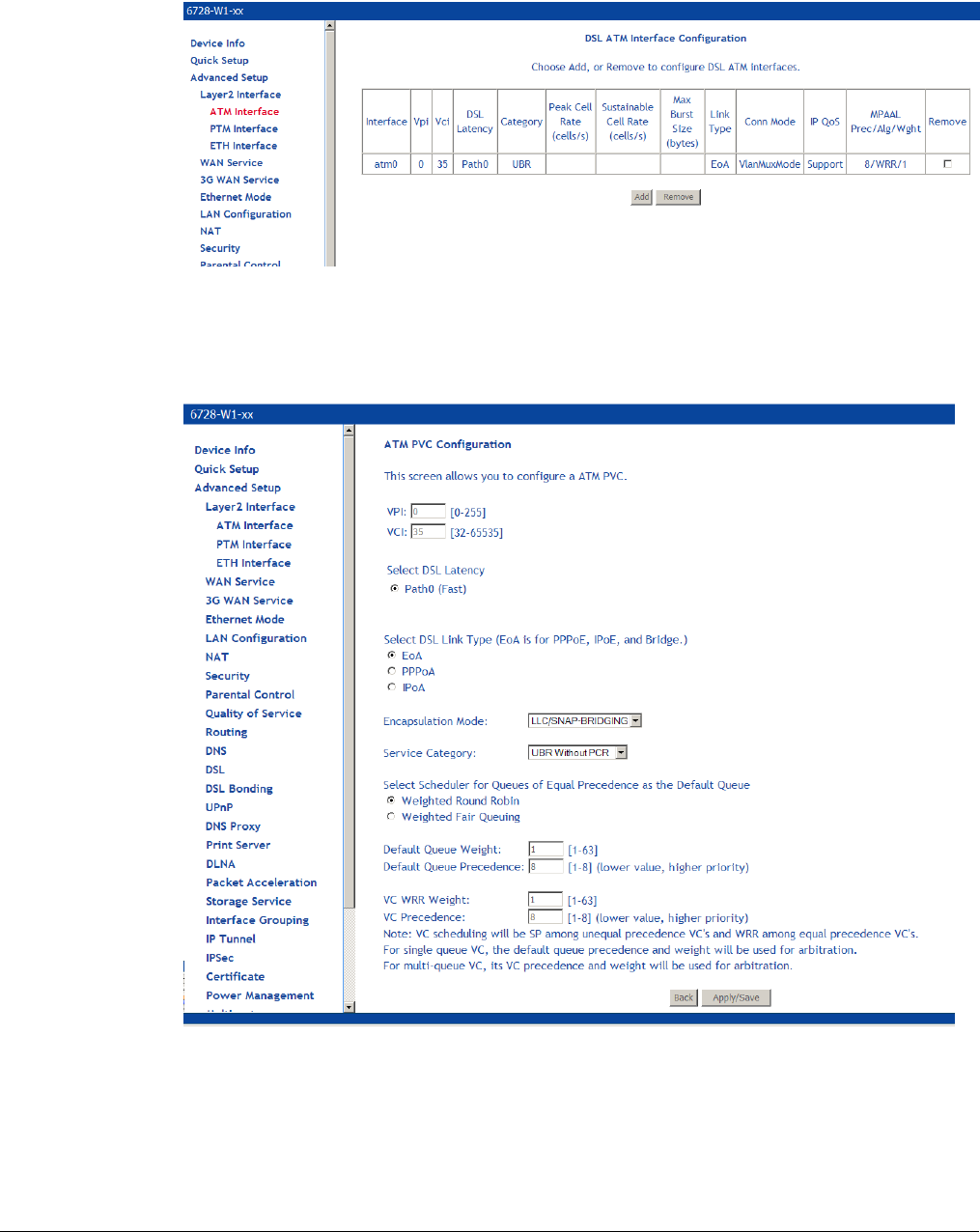
Add an ATM Layer 2 Interface
1. In the left hand menu pane, click Advanced Setup.
2. Under Advanced Setup, click Layer2 Interface then ATM Interface, then click the Add
button.
3. In the VPI and VCI text boxes enter appropriate VPI/VCI numbers.
VPI/VCI (Virtual Path Identifier/Virtual Circuit Identifier) values essentially define the “pipe”
which sends data from the upstream device to the gateway. The VPI/VCI values will be
given to you by your ISP.
4. In the DSL Latency field, select Fast and/or Interleaved.
Use the default settings. Only change to increase precedence if the interface is dedicated
for video or voice applications.

66xx/67xx Router Users Guide 53
5. Under Select DSL Link Type select the appropriate DSL link type: Select EoA for PPPoE,
IPoE, and Bridge connections.
6. From the Encapsulation Mode drop down select the appropriate option:
For EoA options (PPPoE, IPoE, Bridge) select LLC/SNAP BRIDGING
For PPPoA select VC/MUX
For IPoA select LLC/SNAP ROUTING
7. From the Service Category drop down select the type of service.
The service category selection will be provided by your ISP. The service category defines
five classes of traffic:
UBR Without PCR (Unspecified Bit Rate without Peak Cell Rate)—UBR service is suitable
for applications that can tolerate variable delays and some cell losses. Applications suitable
for UBR service include text/data/image transfer, messaging, distribution, and retrieval and
also for remote terminal applications such as telecommuting.
UBR With PCR (Unspecified Bit Rate with Peak Cell Rate).
• Specify a Peak cell Rate. The Peak cell rate is 1-3442 (cells / sec).
CBR (Constant Bit Rate): used by applications that require a fixed data rate that is
continuously available during the connection time. It is commonly used for
uncompressed audio and video information such as videoconferencing, interactive audio
(telephony), audio / video distribution (e.g. television, distance learning, and pay-per-
view), and audio / video retrieval (e.g. video-on-demand and audio library).
• Specify a Peak cell Rate. The Peak Cell Rate is rate is 1-3442 (cells / sec).
Non Realtime VBR (Non-Real-time Variable Bit Rate): can be used for data transfers
that have critical response-time requirements such as airline reservations, banking
transactions, and process monitoring.
• Specify a Peak cell Rate. The Peak Cell Rate is rate is 1-3442 (cells / sec).
• Sustainable Cell Rate. The maximum Sustainable Cell Rate is rate is 1-3442
(cells / sec).1-3442 (cells / sec).
• Maximum Burst Size. The maximum number of contiguous cells that can be sent
at the Peak Cell Rate. The maximum burst size is 1-1000000 (cells / sec).
Realtime VBR (Real-time Variable Bit Rate)—used by time-sensitive applications such
as real-time video. Rt-VBR service allows the network more flexibility than CBR.
• Specify a Peak cell Rate. The Peak Cell Rate is rate is 1-3442 (cells / sec).
• Sustainable Cell Rate. The maximum Sustainable Cell Rate is rate is 1-3442
(cells / sec).1-3442 (cells / sec).
• Maximum Burst Size. The maximum number of contiguous cells that can be sent
at the Peak Cell Rate. The maximum burst size is 1-1000000 (cells / sec).
If using UBR without PCR, select the IP Quality of Service (QoS) algorithm. The options
are Weighted Round Robin or Weighted Fair Queuing.
8. Select the queuing option, either Weighted Round Robin or Weighted Fair Queuing.
Use the default values unless directed by your ISP to change the values.
9. Click Apply/Save to add the appropriate WAN service.
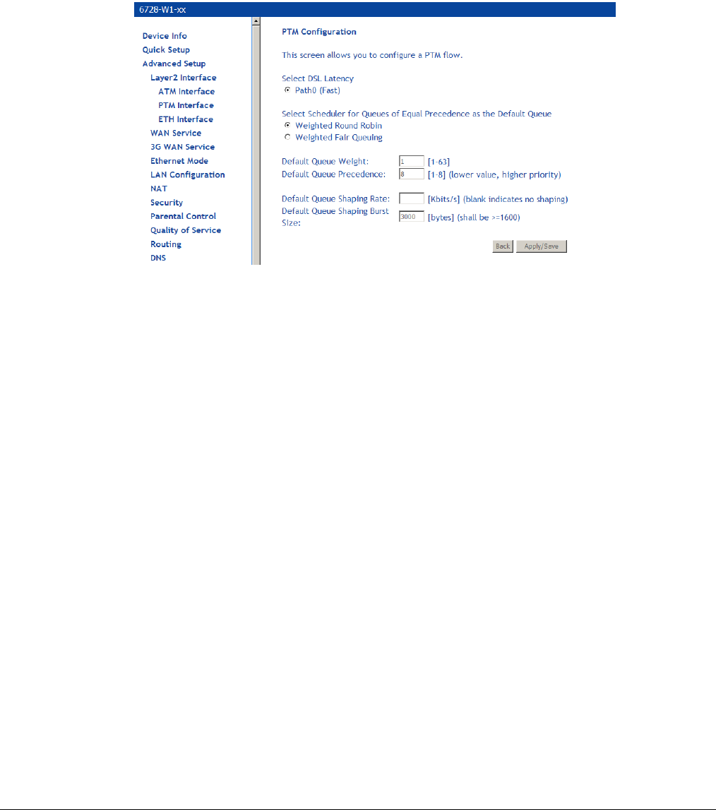
66xx/67xx Router Users Guide 54
Add a PTM Layer 2 Interface
1. In the left hand menu pane, click Advanced Setup.
2. Under Advanced Setup, click Layer2 Interface then PTM Interface, then click the Add
button.
3. Select Weighted Round Robin or Weighted Fair Queuing.
4. Enter a Default Queue Weight and a Default Queue Precedence.
5. Enter a Default Queue Shaping Rate and a Default Queue Shaping Burst Rate.
6. Click Apply/Save to add the appropriate WAN service.
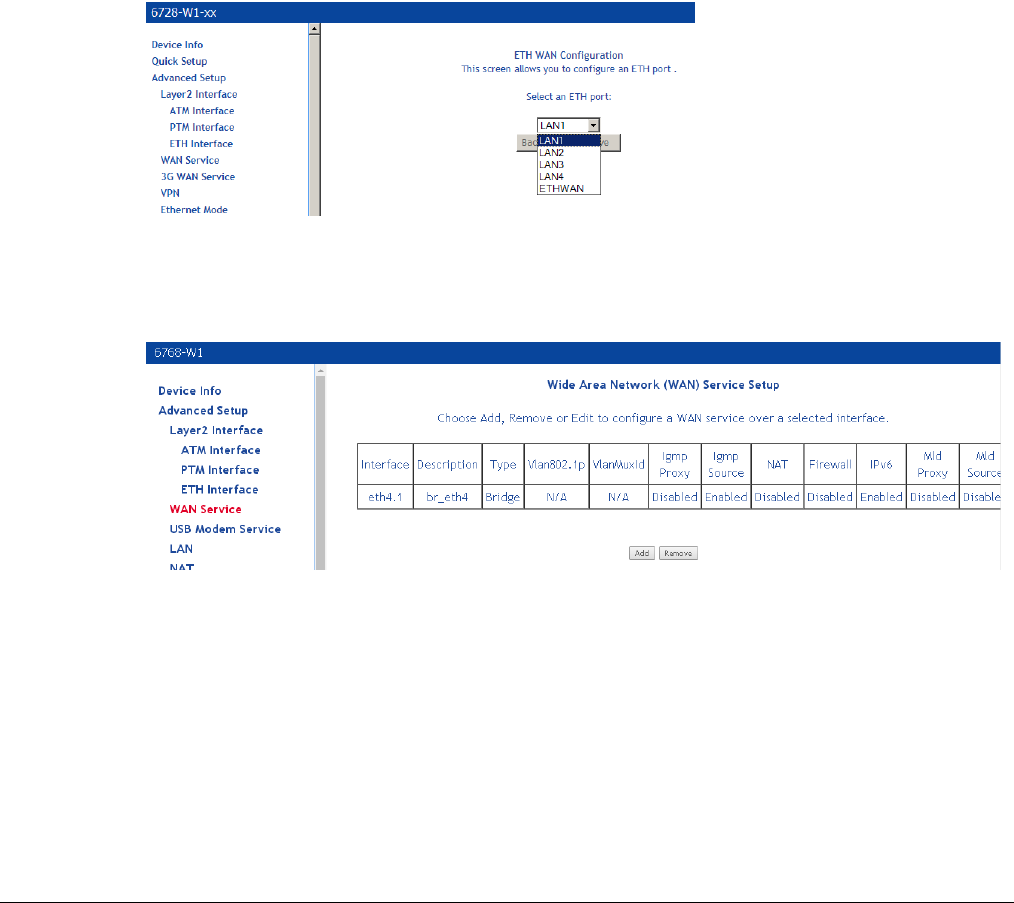
66xx/67xx Router Users Guide 55
Add an Ethernet Layer 2 WAN Interface
You can specify any of the gateway’s Ethernet ports as a WAN interface or LAN interface. In
other words, the GE WAN (ETHWAN) interface may be used as a LAN interface, and any of
LAN1, LAN2, LAN3 and LAN 4 may be used as a WAN interface. Only one of the Ethernet
interfaces may be selected as a WAN interface. All of the other Ethernet interfaces may be use
as LAN interfaces.
1. In the left hand menu pane, click Advanced Setup.
2. Under Advanced Setup, click Layer2 Interface then ETH Interface, then click the Add
button.
3. Select the Ethernet port for the WAN interface.
Normally you would select ETHWAN, the GigE Ethernet port, though one of the LAN ports
could be selected as well.
4. Click Apply/Save to add the appropriate WAN service.
WAN Service
Use the WAN Service page to create a PPPoE, IPoE or Bridging Interface.
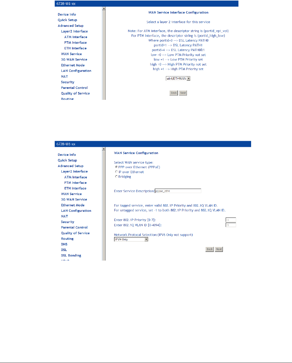
66xx/67xx Router Users Guide 56
Add a PPPoE WAN Service
1. Add an EoA Layer 2 interface or an Ethernet WAN interface as described above (see Add an
ATM Layer 2 Interface on page 52).
2. Under Advanced Setup click WAN Service then click Add.
3. On the WAN Service Interface Configuration page, select the interface associated with the
PPPOE interface from the drop down, then click Next.
4. On the WAN Service Configuration page, select PPP over Ethernet (PPPoE).
5. Optionally enter a name if you wish to customize the description shown for the service.
6. Optionally specify the 801.1P priority and 802.1Q VLAN tagging parameters, and then click
Next. For untagged service, set the parameter to -1 to both 802.1P and 802.1Q VLAN ID.
By default the 802.1P and 802.1Q values are set to -1, which means that the parameters
are ignored.
7. Specify the address type, IPv4 only or dual stack (IPv4 and IPv6).
The IPv6 option enables IPv6 on the WAN interface. Use only when IPv6 is required.
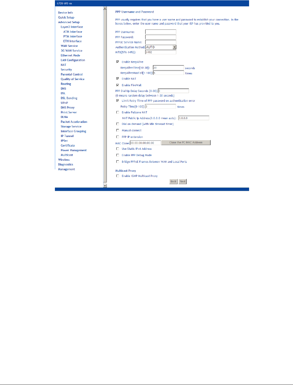
66xx/67xx Router Users Guide 57
8. Click Next.
9. On the PPP Username and Password page you will need the following information:
PPP Username: Your account from ISP to access Internet.
PPP Password: The password assigned by your ISP.
Note: If you set the username/password to default/default, the modem will redirect the
user to a web page within the modem to change their password when they first log on.
PPPoE Service Name: Server name of network ISP. No need to set this.
Authentication Method: Authentication mode of network ISP. Default is AUTO.
MTU: the Maximum transmission unit (MTU) value may be set for your needs. Higher
MTU can provide for a more efficient link because each packet will carry more data while
the overhead in the packet such as header information does not get larger with the size
of the packet. So the bulk throughput on the link will go up. Generally a large packet size
can occupy the time on the link, so the higher MTU can increase lag time and minimum
latency which is not appropriate for all applications.
MTU size can be 576-1492.
Enable KeepAlive:
• KeepAlive Time: The interval in which the PPPoE client will send out keep alive
message to the PPPoE server to keep the PPPoE session up.
• KeepAlive Max Fail: The maximum number of retries the gateway will attempt if the
PPP client encounters an error. For example if the number is 1 the gateway will only
retry once.
Enable NAT: Enables Network Address Translation. See NAT on page 81.
Enable FireWall: Enables Firewall. See Firewall on page 85.
PPP Dial Up Delay Seconds: The number of seconds the gateway will pause before

66xx/67xx Router Users Guide 58
attempting PPP authentication. The default (0) means that the gateway will pause a
random number of seconds before attempting authentication. This helps prevents the
PPP server from being flooded with authentication requests after a power shutdown or a
reset.
Limit Retry Time of PPP Password on Authentication Error: Number of times the
gateway should re-attempt PPPoE authentication after a failure. When the Retry Timer is
disabled, the device will keep retrying using the PPP username and password.
NAT Public Address (available if NAT is enabled). Enter 0.0.0.0 to specify that the
device should use pubic IP addresses provided by the network.
Enable Fullcone NAT: RFC 3489 defines four types of Network Address Translation
(NAT). Fullcone NAT. As with other types of NAT there is a mapping from a public IP
address to a private IP address. The external public IP address is extended with the
external port. With Fullcone NAT once the mapping is created any external host may
send packets to the private IP address by sending to the external IP address and port.
Other types of NAT have restrictions such as the sending IP address must initially have
had packets sent from the private IP address and port regardless of the external port, or
from the private IP address and the external port.
Dial on demand: When this mode is selected, the connection that has no traffic within
assigned disconnect timeout (e.g. 1 minute) will be automatically disconnected. The
connection will be activated again when traffic arrives. This function is advantageous for
users who are charged with online time. It should be noted that some programs
automatically link to Internet. Connections will not be disconnected under these data
streams.
• Inactivity Timeout: When Dial on demand is selected, this input box indicates that
after how long the connection will be disconnected in the absence of traffic. If the
value is 0, connection will not be disconnected.
Manual Connect: connect/disconnect PPPoE connection manually
PPP IP extension: Allows only one PC on the LAN. The public IP address assigned by
the remote using the PPP/IPCP protocol is actually not used on the WAN PPP interface.
Instead, it is forwarded to the PC’s LAN interface through DHCP.
Only one PC on the LAN can be connected to the remote since the DHCP server within
the VDSL gateway has only a single IP address to assign to a LAN device. NAT and
firewall are disabled when this option is selected. The VDSL gateway becomes the
default gateway and DNS server to the PC through DHCP using the LAN interface IP
address. The VDSL gateway extends the IP subnet at the remote service provider to the
LAN PC. That is, the PC becomes a host belonging to the same IP subnet. The VDSL
gateway bridges the IP packets between WAN and LAN ports, unless the packet is
addressed to the gateway’s LAN IP address.
MAC Clone: Clicking the Clone the PC MAC Address button will use the MAC address
from the connected PC for the MAC address of the gateway.
Use Static Ipv4 Address: Enter the Static IP V4 address
Enable PPP Debug Mode: Used to debug PPPoE issues. Use only when instructed by
your ISP.
Bridge PPPoE Frames Between WAN and Local Ports: By default the bridge PPPoE
frame between WAN and local ports is on. This allows a PC behind the modem to be the
PPPoE termination point. PPPoE authentication is passed on to the PC instead of to the
gateway. If there are multiple PCs then, each one will have a PPPoE authentication. Note
that this option is not applicable for PPPoA.
Enable IGMP Multicast Proxy: Configures the gateway for IGMP snooping so the
gateway can keep limit multicast traffic.
Enable MLD Multicast Proxy: Configures the gateway to act as a proxy by issuing MLD
host messages for the hosts that have been discovered through MLD interfaces.
Enable MLD Multicast Proxy is for IGMP in IPv6 mode.
10. Click Next.
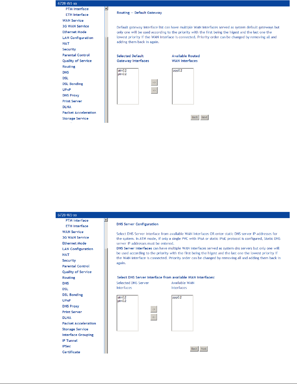
66xx/67xx Router Users Guide 59
11. On the Routing — Default Gateway page set the priority of WAN interfaces used as default
gateways then click Next
If multiple WAN interfaces are configured, you can define the priority by their position in the
Selected Default Gateway Interfaces window. The default gateway will use the first
Interface that comes up.
Change the priority order by removing all items from the Selected Default Gateway
Interfaces window by selecting them, then clicking the right arrow button. Select the items in
the priority order, then click the left arrow to move them into the Selected Default Gateway
Interfaces window.
12. On the DNS Server Configuration page set the priority of WAN interfaces to be used as
DNS server interfaces, or specify a static DNS Primary and Secondary server, and then click
Next.
If multiple WAN interfaces are configured, you can define the priority by their position in the
Selected DNS Server Interfaces window. Top is the highest priority; bottom the lowest.
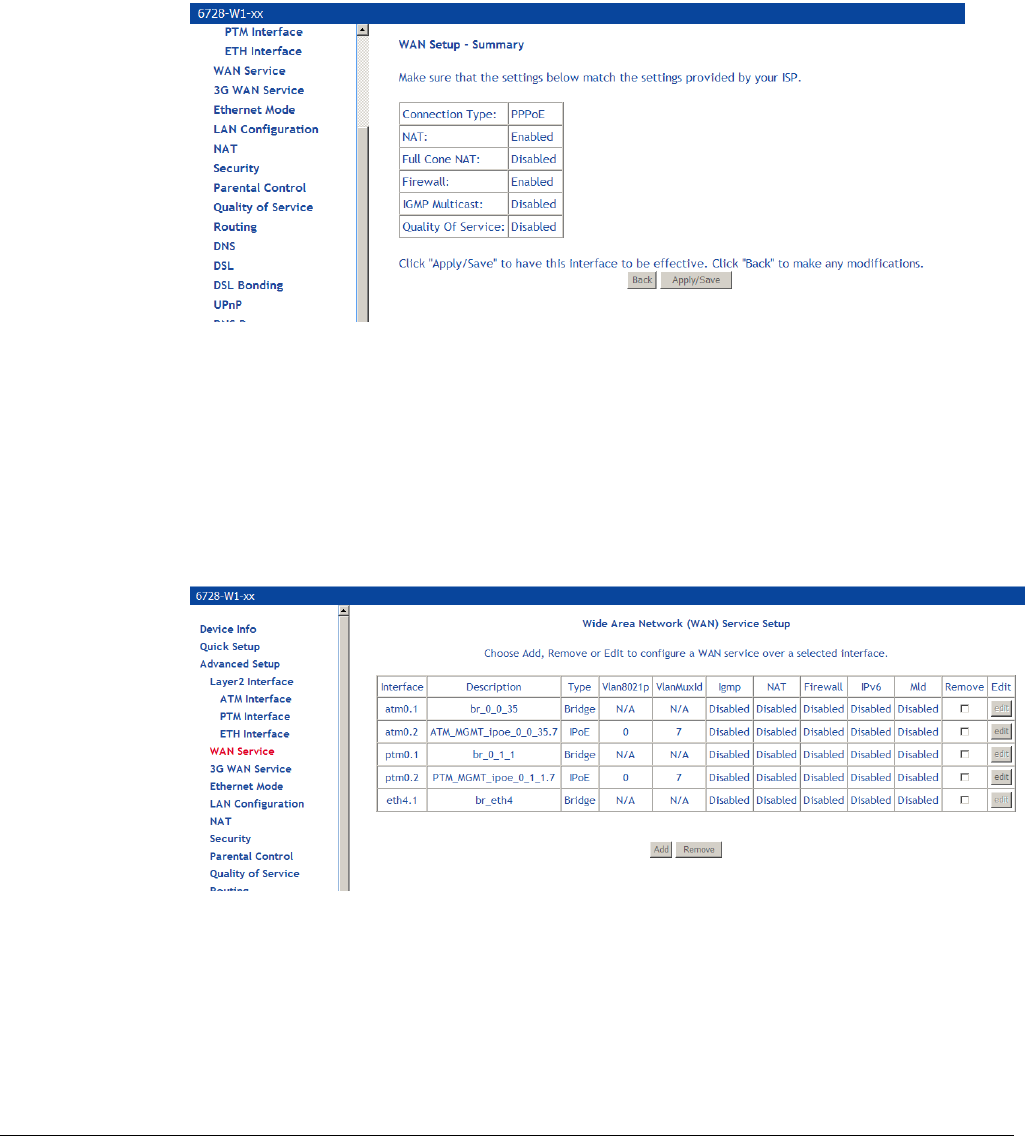
66xx/67xx Router Users Guide 60
Change the priority order by removing all items from the Selected DNS Server Interfaces
window by selecting them, then clicking the right arrow button. Select the items in the priority
order, then click the left arrow to move them into the Selected DNS Server Interfaces
window.
For a Static DNS IP Address, enter a primary and secondary DNS server for your modem.
13. On the WAN Setup – Summary page, review your settings and click Apply/Save to accept
the settings. To change your settings, click the Back button on the WAN Setup – Summary
page (do not click the browser Back button).
In the Wide Area Network (WAN) Service Setup page, you will see the new WAN interface
added.
Add an IPoE WAN Service
1. Add an EoA Layer 2 interface or an Ethernet WAN interface as described above (see Add an
ATM Layer 2 Interface on page 52).
2. Under Advanced Setup click WAN Service then click Add.
3. On the WAN Service Interface Configuration page, select the interface associated with the
IPoE interface from the drop down, then click Next.
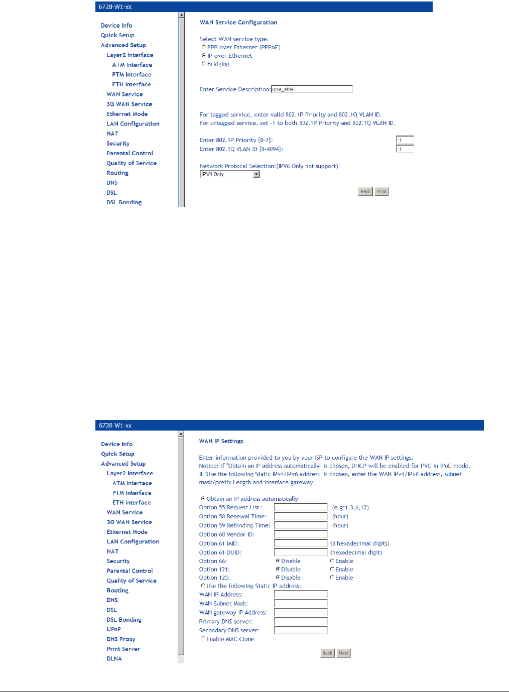
66xx/67xx Router Users Guide 61
4. On the WAN Service Configuration page, select IP over Ethernet.
5. Optionally specify the 801.1P priority and 802.1Q VLAN tagging parameters, and then click
Next. For untagged service, set the parameter to -1 to both 802.1P and 802.1Q VLAN ID.
By default the 802.1P and 802.1Q values are set to -1, which means that the parameters
are ignored.
6. Specify the address type, IPv4 only or dual stack (IPv4 and IPv6).
The IPv6 option enables IPv6 on the WAN interface. Use only when IPv6 is required.
7. Click Next.
8. On the WAN IP Settings page you will need to enter information provided by your ISP, then
click Next.
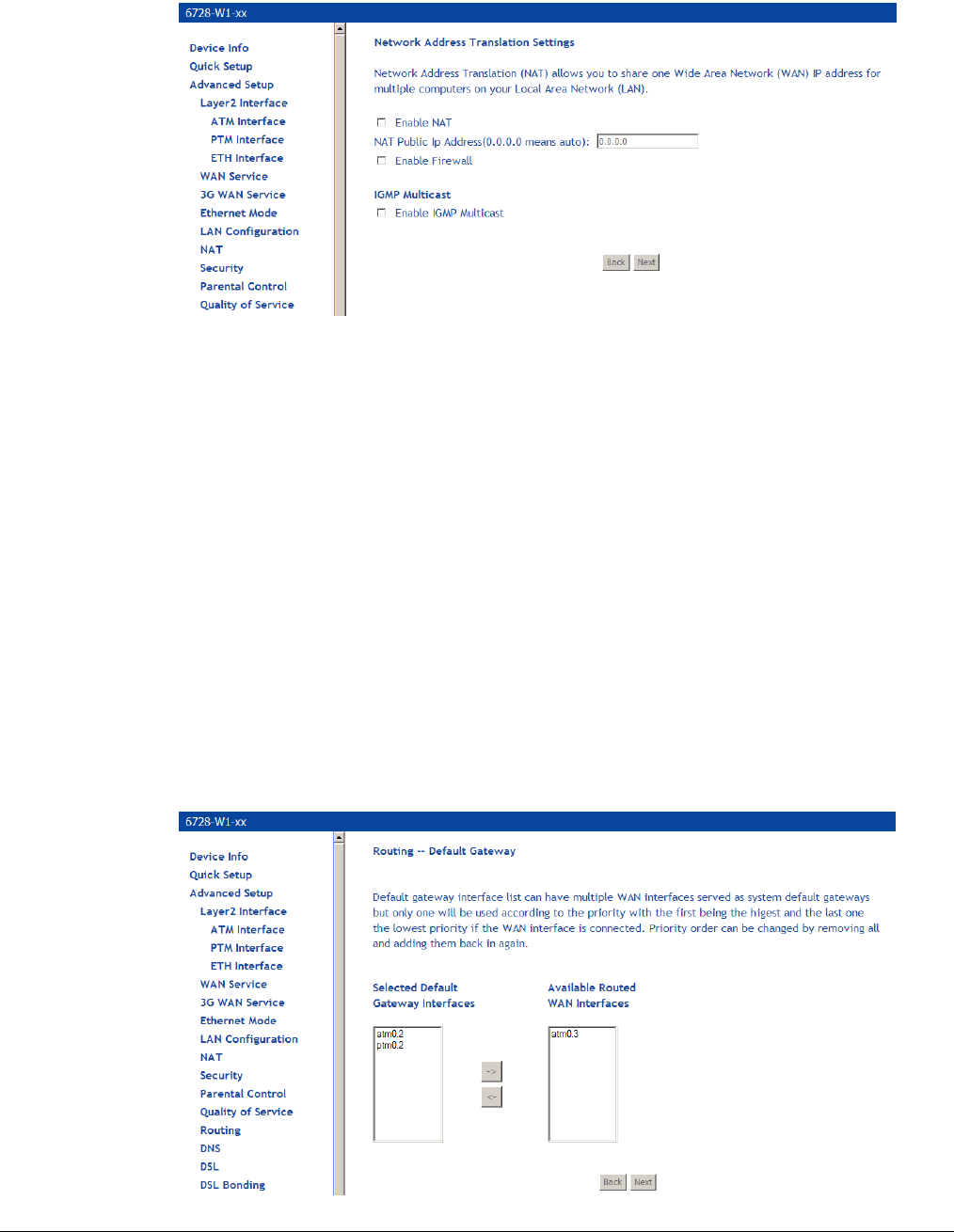
66xx/67xx Router Users Guide 62
9. On the Network Address Translation Settings you will need to enter information provided
by your ISP, then click Next.
Enable NAT must be checked for Fullcone NAT to be used.
• NAT Public Address (available if NAT is enabled). Enter 0.0.0.0 to specify that the
device should use pubic IP addresses provided by the network.
• Enable Fullcone NAT: RFC 3489 defines four types of Network Address Translation
(NAT).
Fullcone NAT. As with other types of NAT there is a mapping from a public IP
address to a private IP address. The external public IP address is extended with the
external port. With Fullcone NAT once the mapping is created any external host may
send packets to the private IP address by sending to the external IP address and
port. Other types of NAT have restrictions such as the sending IP address must
initially have had packets sent from the private IP address and port regardless of the
external port, or from the private IP address and the external port.
Enable Firewall: Enables Firewall.
Enable IGMP Multicast: Configures the gateway for IGMP snooping so the gateway can
keep limit multicast traffic.
10. Click Next.
11. On the Routing — Default Gateway page set the priority of WAN interfaces used as default
gateways then click Next.
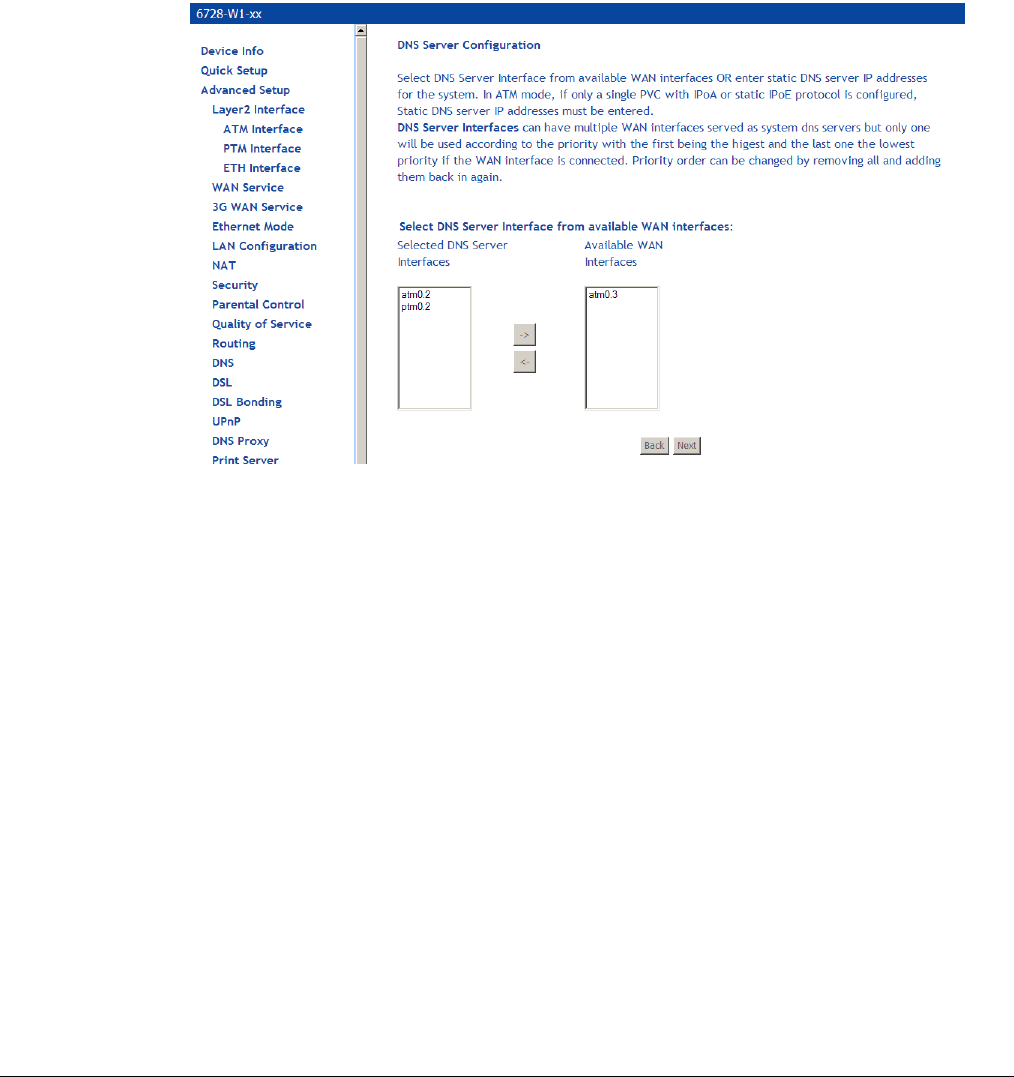
66xx/67xx Router Users Guide 63
If multiple WAN interfaces are configured, you can define the priority by their position in the
Selected Default Gateway Interfaces window. Top is the highest priority; bottom the
lowest.
Change the priority order by removing all items from the Selected Default Gateway
Interfaces window by selecting them, then clicking the right arrow button. Select the items in
the priority order, then click the left arrow to move them into the Selected Default Gateway
Interfaces window.
12. On the DNS Server Configuration page set the priority of WAN interfaces to be used as
DNS server interfaces, or specify a static DNS Primary and Secondary server, then click
Next.
If multiple WAN interfaces are configured, you can define the priority by their position in the
Selected DNS Server Interfaces window. Top is the highest priority; bottom the lowest.
Change the priority order by removing all items from the Selected DNS Server Interfaces
window by selecting them, then clicking the right arrow button. Select the items in the priority
order, then click the left arrow to move them into the Selected DNS Server Interfaces
window.
For a Static DNS IP Address, enter a primary and secondary DNS server for your modem,
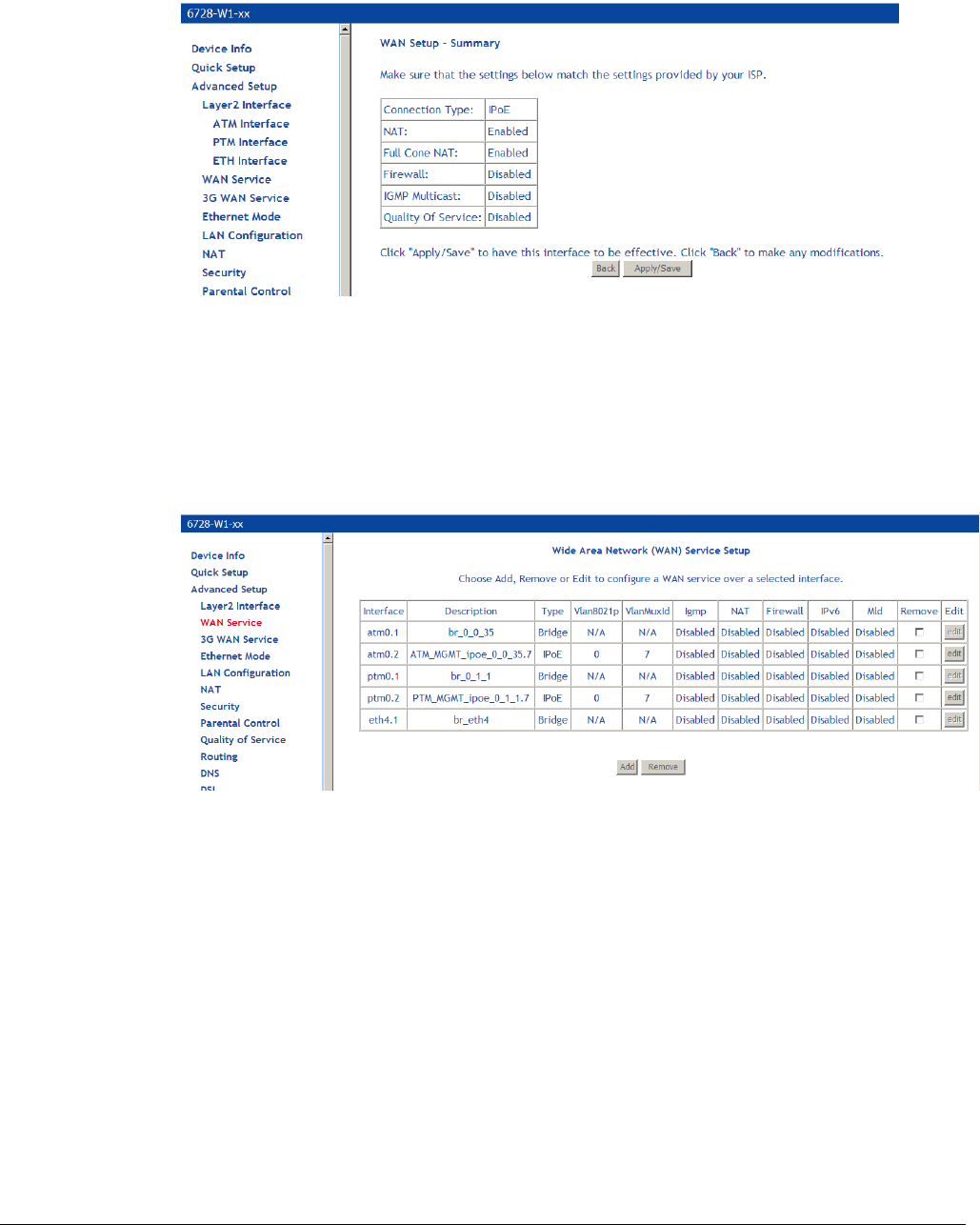
66xx/67xx Router Users Guide 64
13. On the WAN Setup – Summary page review your settings and click Apply/Save to accept
the settings. To change your settings, click the Back button on the WAN Setup – Summary
page (do not click the browser Back button).
In the Wide Area Network (WAN) Service Setup page, you will see the new WAN interface
added.
Add a Bridge WAN Service
1. Add an EoA Layer 2 interface as described above (see Add an ATM Layer 2 Interface on
page 52.)
2. Under Advanced Setup click WAN Service then click Add.
3. On the WAN Service Interface Configuration page, select the interface associated with the
bridge interface from the drop down, and then click Next.
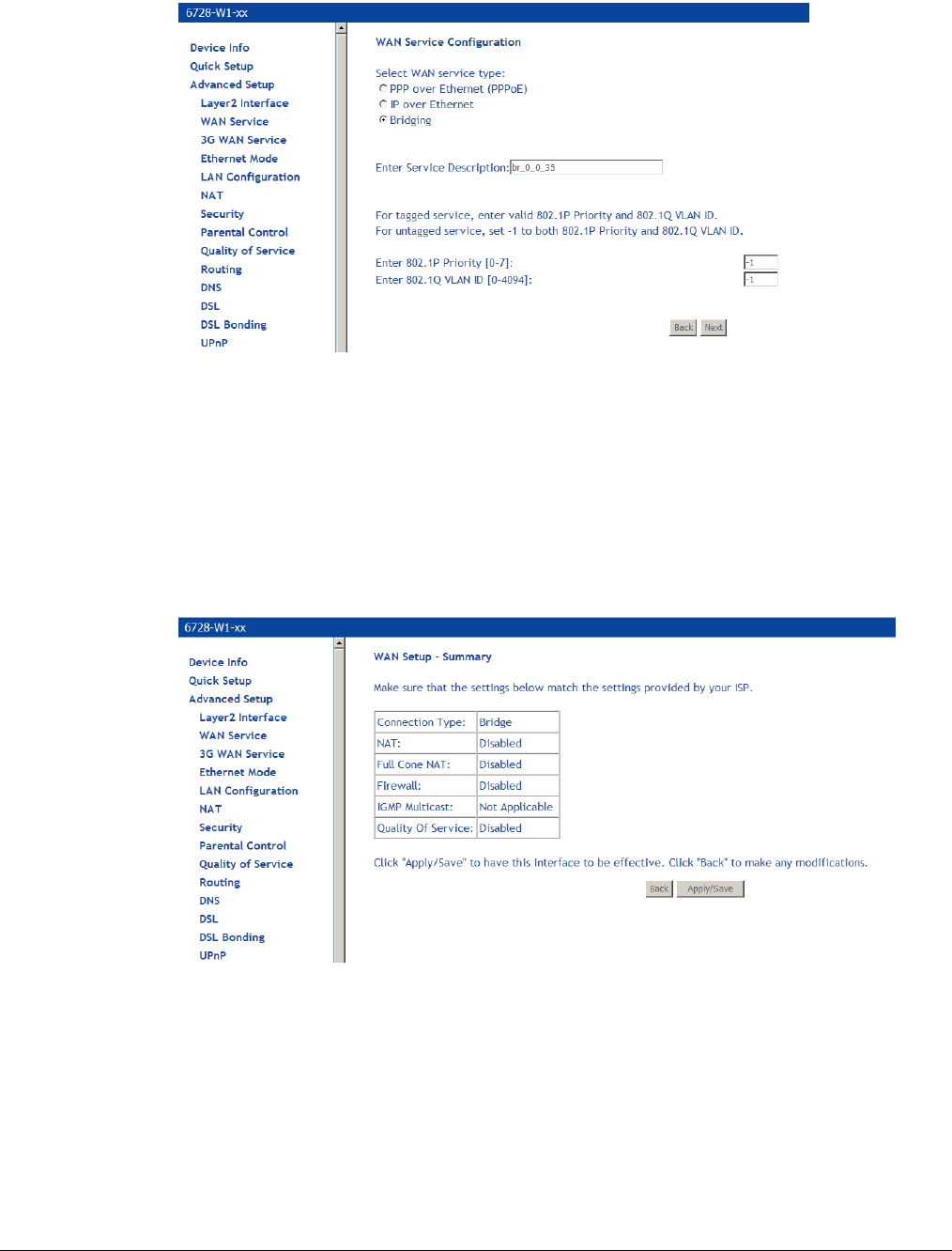
66xx/67xx Router Users Guide 65
4. On the WAN Service Configuration page, select Bridging
14. Optionally specify the 801.1P priority and 802.1Q VLAN tagging parameters, and then click
Next. For untagged service, set the parameter to -1 to both 802.1P and 802.1Q VLAN ID.
By default the 802.1P and 802.1Q values are set to -1, which means that the parameters
are ignored.
5. Click Next.
6. In the WAN Setup – Summary page, review the settings for this interface. Click Apply/Save
to accept the settings.
If you made a mistake on the configuration and want to make changes to it, select the
Remove check box and click the Remove button.
In the Wide Area Network (WAN) Service Setup page, you will see the new WAN interface
added.
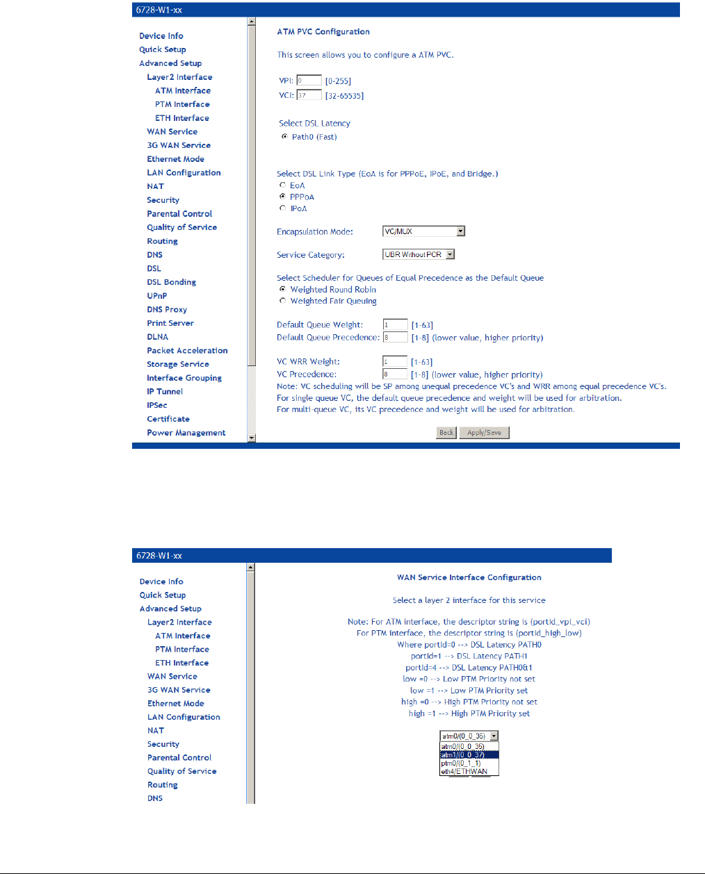
66xx/67xx Router Users Guide 66
Add a PPPoA WAN Service
1. Add a PPPoA Layer 2 interface as described above (see Add an ATM Layer 2 Interface on
page 52).
2. Under Advanced Setup click WAN Service then click Add.
3. On the WAN Service Interface Configuration page, select the link associated with the
PPPoA interface from the drop down, and then click Next.
4. On the WAN Service Configuration page, enter a name if you wish to customize the
description shown for the service.

66xx/67xx Router Users Guide 67
5. Specify the address type, IPv4 only or dual stack (IPv4 and IPv6).
6. Click Next.
7. On the PPP Username and Password page you will need to enter information provided by
your ISP. When you are done, click Next.
PPP Username: Your account from ISP to access Internet.
PPP Password: The password assigned by your ISP.
Authentication Method: Authentication mode of network ISP. Default is AUTO.
MTU: the Maximum transmission unit (MTU) value may be set for your needs. Higher
MTU can provide for a more efficient link because each packet will carry more data while
the overhead in the packet such as header information does not get larger with the size
of the packet. So the bulk throughput on the link will go up. Generally a large packet size
can occupy the time on the link, so the higher MTU can increase lag time and minimum
latency which is not appropriate for all applications.
Enable KeepAlive: Enables/disables TCP keep alive packets.
• KeepAlive Timer: When Enable KeepAlive is selected, this input box indicates
how often the device should send keep alive packets.
• KeepAlive Max Fail: Number of times the gateway should re-attempt the
connection after a failure.
PPP Dial Up Delay Seconds: The number of seconds the gateway will pause before
attempting PPP authentication. The default (0) means that the gateway will pause a
random number of seconds before attempting authentication. This helps prevents the
PPP server from being flooded with authentication requests after a power shutdown or a
reset.
Limit Retry Time of PPP Password on Authentication Error: Number of times the
gateway should re-attempt PPPoE authentication after a failure.
NAT Public Address (available if NAT is enabled). Enter 0.0.0.0 to specify that the
device should use pubic IP addresses provided by the network.
Enable Fullcone NAT: RFC 3489 defines four types of Network Address Translation
(NAT). Fullcone NAT. As with other types of NAT there is a mapping from a public IP
address to a private IP address. The external public IP address is extended with the
external port. With Fullcone NAT once the mapping is created any external host may
send packets to the private IP address by sending to the external IP address and port.
Other types of NAT have restrictions such as the sending IP address must initially have
had packets sent from the private IP address and port regardless of the external port, or
from the private IP address and the external port.
Dial on demand: When this mode is selected, the connection that has no traffic within
assigned disconnect timeout (e.g. 1 minute) will be automatically disconnected. The
connection will be activated again when traffic arrives. This function is advantageous for
users who are charged with online time. It should be noted that some programs
automatically link to Internet. Connections will not be disconnected under these data
streams.
• Inactivity Timeout: When Dial on demand is selected, this setting indicates that
after how long the connection will be disconnected in the absence of traffic. If the
value is 0, connection will not be disconnected.
Manual Connect: connect/disconnect PPPoE connection manually.
MAC Clone: Clicking the Clone the PC MAC Address button will use the MAC address
from the connected PC for the MAC address of the gateway.
Use Static IPv4 Address: Defines a static IP address (v4) which you enter in the IPv4
Address text box which is displayed when the Use Static IPv4 Address check box is
selected.
Enable PPP Debug Mode: Used to debug PPPoE issues. Use only when instructed by
your ISP.
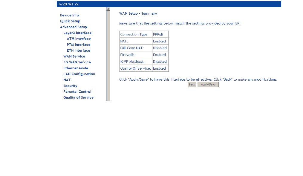
66xx/67xx Router Users Guide 68
Enable IGMP Multicast Proxy: Configures the gateway for IGMP snooping so the
gateway can keep limit multicast traffic.
8. On the Routing — Default Gateway page set the priority of WAN interfaces used as default
gateways then click Next
If multiple WAN interfaces are configured, you can define the priority by their position in the
Selected Default Gateway Interfaces window. Top is the highest priority; bottom the
lowest.
Change the priority order by removing all items from the Selected Default Gateway
Interfaces window by selecting them, then clicking the right arrow button. Select the items in
the priority order, then click the left arrow to move them into the Selected Default Gateway
Interfaces window.
9. On the DNS Server Configuration page set the priority of WAN interfaces to be used as
DNS server interfaces then click Next
If multiple WAN interfaces are configured, you can define the priority by their position in the
Selected DNS Server Interfaces window. Top is the highest priority; bottom the lowest.
Change the priority order by removing all items from the Selected DNS Server Interfaces
window by selecting them, then clicking the right arrow button. Select the items in the priority
order, then click the left arrow to move them into the Selected DNS Server Interfaces
window.
For a Static DNS IP Address, enter a primary and secondary DNS server for your modem,
10. On the WAN Setup – Summary page review your settings and click Apply/Save to accept
the settings. To change your settings, click the Back button on the WAN Setup – Summary
page (do not click the browser Back button).
In the Wide Area Network (WAN) Service Setup page, you will see the new WAN interface
added.
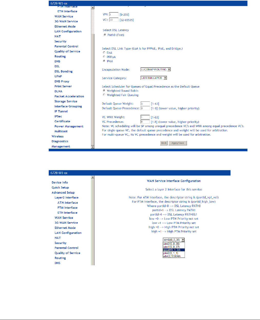
66xx/67xx Router Users Guide 69
Add an IPoA WAN Service
1. Add an IPoA Layer 2 interface as described above (see Add an ATM Layer 2 Interface on
page 52).
1. Under Advanced Setup click WAN Service then click Add.
2. WAN Service Interface Configuration page, select the interface associated with the IPoA
interface from the drop down, then click Next
3. On the WAN Service Configuration page, enter a name if you wish to customize the
description shown for the service, then click Next.
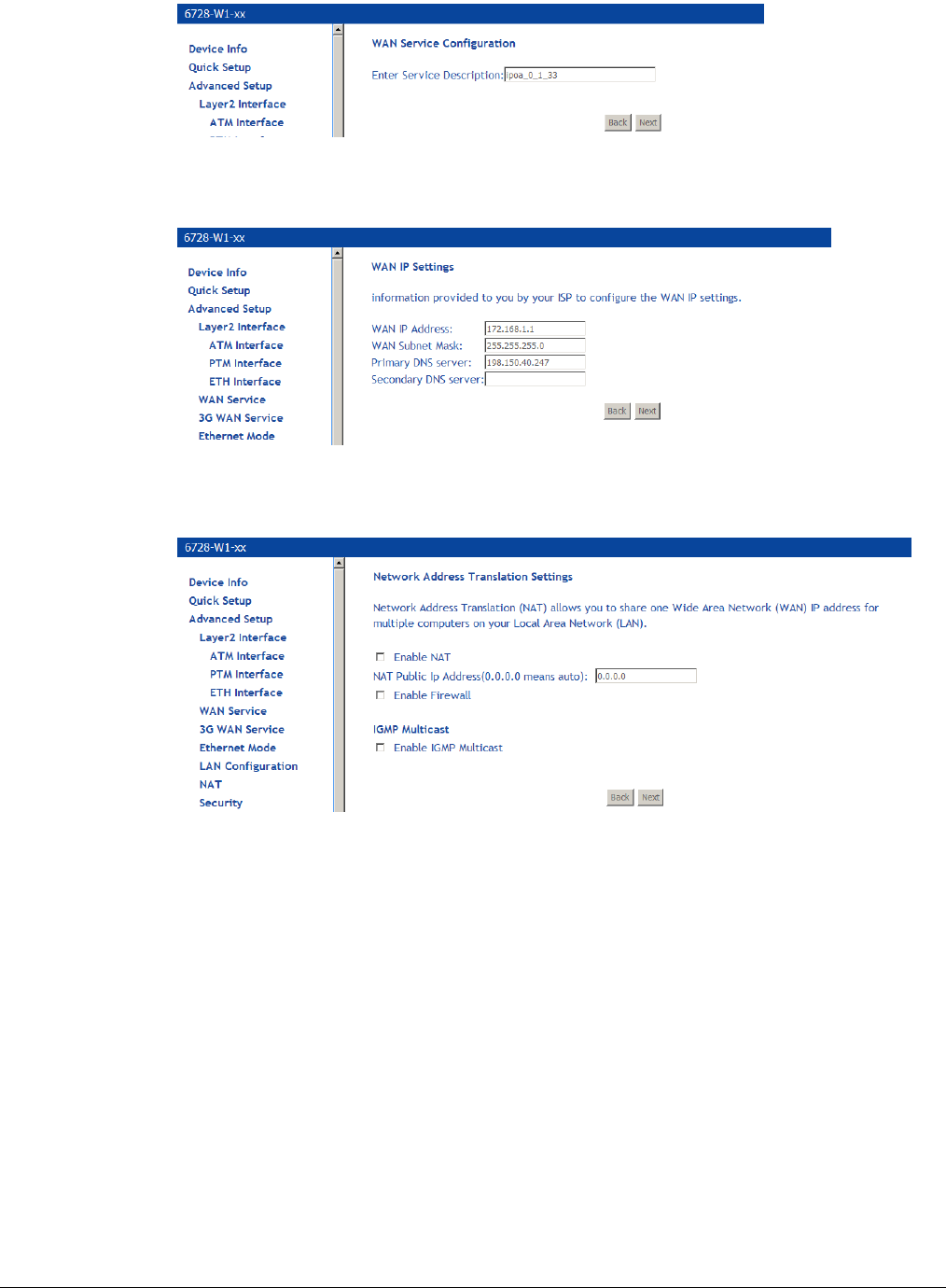
66xx/67xx Router Users Guide 70
4. On the WAN IP Settings page enter a WAN IP address, WAN subnet mask, and DNS
server settings as instructed by your ISP, then click Next.
5. On the Network Address Translation Settings you will need to enter information provided
by your ISP, then click Next.
Enable NAT must be checked for Fullcone NAT to be used.
• NAT Public Address (available if NAT is enabled). Enter 0.0.0.0 to specify that the
device should use pubic IP addresses provided by the network.
• Enable Fullcone NAT: RFC 3489 defines four types of Network Address Translation
(NAT). Fullcone NAT. As with other types of NAT there is a mapping from a public IP
address to a private IP address. The external public IP address is extended with the
external port. With Fullcone NAT once the mapping is created any external host may
send packets to the private IP address by sending to the external IP address and
port. Other types of NAT have restrictions such as the sending IP address must
initially have had packets sent from the private IP address and port regardless of the
external port, or from the private IP address and the external port.
Enable Firewall: Enables Firewall.
Enable IGMP Multicast: Configures the gateway for IGMP snooping so the gateway can
keep limit multicast traffic.
6. On the Routing — Default Gateway page set the priority of WAN interfaces used as default
gateways then click Next
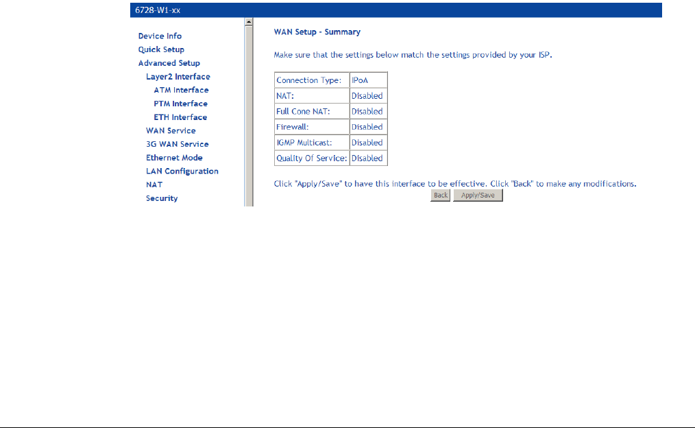
66xx/67xx Router Users Guide 71
If multiple WAN interfaces are configured, you can define the priority by their position in the
Selected Default Gateway Interfaces window. Top is the highest priority; bottom the
lowest.
Change the priority order by removing all items from the Selected Default Gateway
Interfaces window by selecting them, then clicking the right arrow button. Select the items in
the priority order, then click the left arrow to move them into the Selected Default Gateway
Interfaces window.
7. On the DNS Server Configuration page set the priority of WAN interfaces to be used as
DNS server interfaces then click Next
If multiple WAN interfaces are configured, you can define the priority by their position in the
Selected DNS Server Interfaces window. Top is the highest priority; bottom the lowest.
Change the priority order by removing all items from the Selected DNS Server Interfaces
window by selecting them, then clicking the right arrow button. Select the items in the priority
order, then click the left arrow to move them into the Selected DNS Server Interfaces
window.
8. For a Static DNS IP Address, enter a primary and secondary DNS server for your modem,
9. On the WAN Setup – Summary page review your settings and click Apply/Save to accept
the settings. To change your settings, click the Back button on the WAN Setup – Summary
page (do not click the browser Back button).
In the Wide Area Network (WAN) Service Setup page, you will see the new WAN interface
added.
10. WAN Setup — Summary
When the settings are complete, the next screen shows a WAN Setup – Summary screen
displaying the WAN configurations made.
Make sure that the settings on the WAN Setup - Summary screen match the settings provided
by your ISP. If all settings are correct, click the Apply/Save button to save these settings; if not,
click Back to make any modifications (do not click the browser Back button).. If you want to
change any item after saving, click Edit to make any modifications.
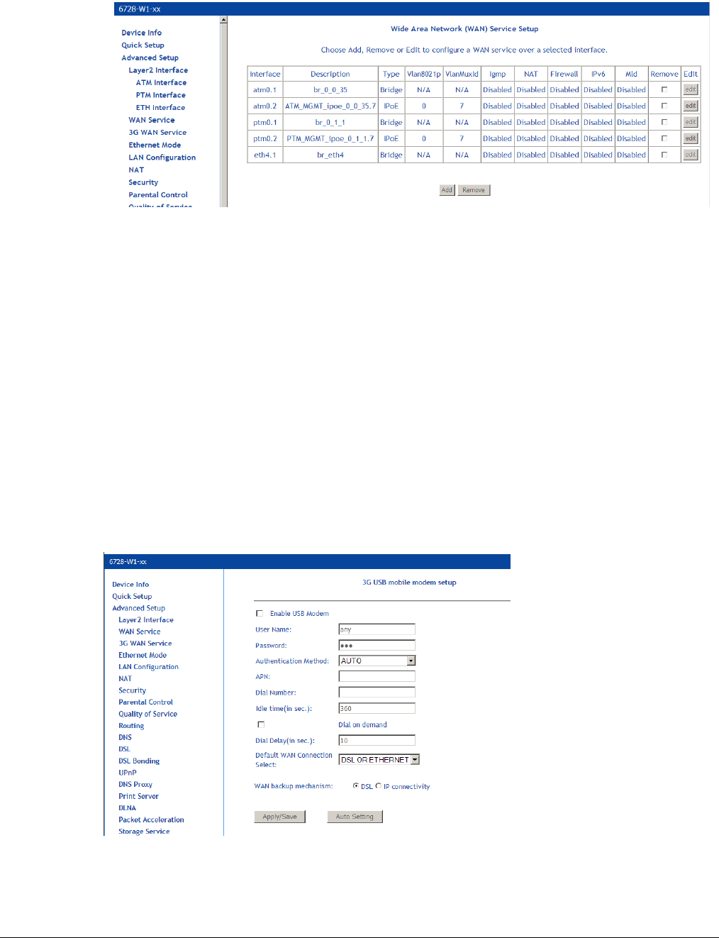
66xx/67xx Router Users Guide 72
After the settings are saved, the below screen will follow displaying the WAN settings that you
made with the option to Add or Remove any of the connections that you have made.
Remove a Connection
If you want to delete a connection from the listed WAN setup, click the Remove check box next to
the connection, then click Remove.
Edit a Connection
If you want to modify a connection from the listed WAN setup, click the Edit button next to the
connection.
NOTE: Some connection settings cannot be edited after they have been created. You will need to
delete and re-add the connection to change some settings.
3G WAN Service
3G WAN service allows you to set up a WAN service for 3G mobile networks as a back up if the
DSL WAN service becomes unavailable.
Some parameters depend on the requirements of the 3G provider.
User Name/Password: Username/password for the dial up 3G WAN service. (Not all providers
require User Name/Password.)
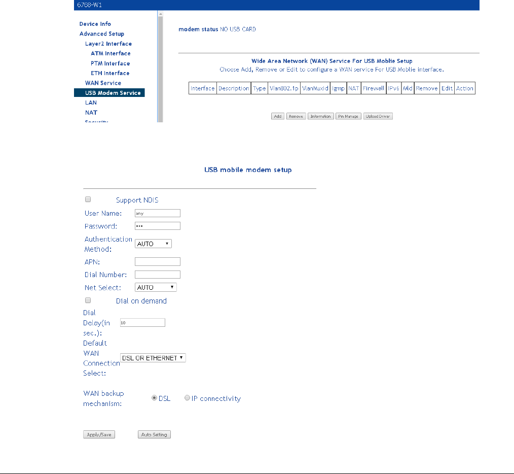
66xx/67xx Router Users Guide 73
Authentication Method Authentication methods for connecting to the 3G mobile network. Auto is
recommended. Please follow the guidance of your ISP.
APN: The name of the access point
Dial Number: The dial up number
Idle time (in sec.): If no activity on the 3G WAN service for the designated duration the 3G
connection will be dropped.
Dial on demand: Leave blank (for manual dialing).
Dial Delay (in sec.): How long from the time DSL stops working before switching to 3G WAN
service mode. Shortening the Dial Delay could lead to excessive use of 3G service.
Default WAN Connection Select: Select the DSL OR ETHERNET option.
WAN backup mechanism: If you are using ADSL or VDSL for the WAN connection, select DSL.
USB Modem Service
USB Modem Service page displays the USB Modem service. Click add to create a USB Modem
service.
USB mobile modem setup
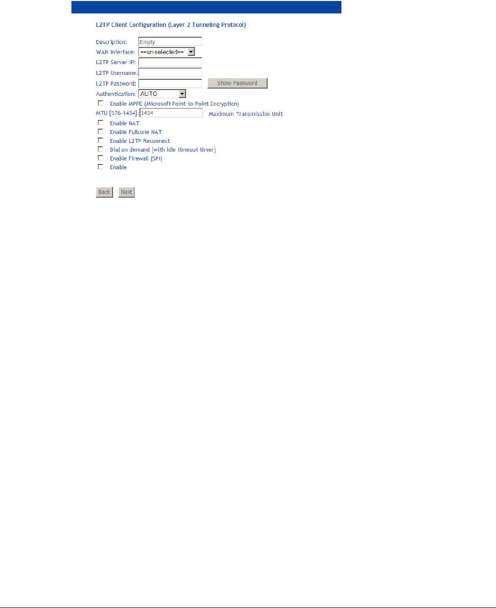
66xx/67xx Router Users Guide 74
VPN
The VPN (Virtual Private Network) option creates a layer 2 tunnel, so even though separated by
distance and other intervening layer 2 devices, the downstream devices appears to be on the
same IP subnet.
The Layer 2 connection uses Point to Point Protocol (PPP). A PPPoE WAN interface must be
created first so it can be selected as the WAN Interface.
Description: A descriptive name for the VPN tunnel
WAN Interface: The WAN Interface for the VPN tunnel.
L2TP Server IP: The IP address for the Layer 2 server.
L2TP Username/Password: The username and password to connect to the Layer 2 server.
Authentication: The authentication method to use when connecting to the Layer 2 server.
Enable MPPE: Enables Microsoft Point-to-Point Encryption.
MTU: The Maximum Transmission Unit size for communications between the device and the
Layer 2 server.
Enable NAT: Enable Network Address Translation.
Enable Fullcone NAT: Enable NAT with extended port numbering for the public IP address.
Enable L2TP Reconnect: Enable reconnection to the Layer 2 Server. When selected, also enter
the snooze time-out PPP in seconds (the amount of time between activities to reconnect)
and the number of retries.
Dial on demand (with idle timeout timer): Enables the ability to dynamically connect to L2TP
server when data is detected on the LAN interface for the L2TP tunnel.
Enable Firewall (SPI): Enables the Firewall with stateful packet inspection.
Once configured, click Next, then in the next screens (as with other WAN interfaces), move the
new Available Routed WAN Interfaces and Available WAN Interface to the selected region for
the Default Gateway and the DNS Server Configuration screens, then click Next and
Apply/Save in the Summary screen.
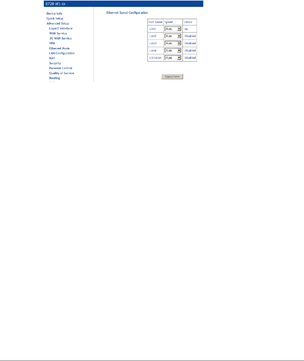
66xx/67xx Router Users Guide 75
Ethernet Mode
Ethernet mode allows you to select the speed of your LAN Ethernet connections. (Configure the
WAN Ethernet interface in the Advanced Setup, Layer 2, ETH Interface screen.) Modes
include—auto, 100 full, 100 half, 10 full and 10 half. If you select auto then the gateway will use
the common mode that all the connected interfaces can operate at.
If the GE WAN port is the Ethernet WAN interface, it may be deleted as an Ethernet WAN
interface, so the port may be used as a LAN port.
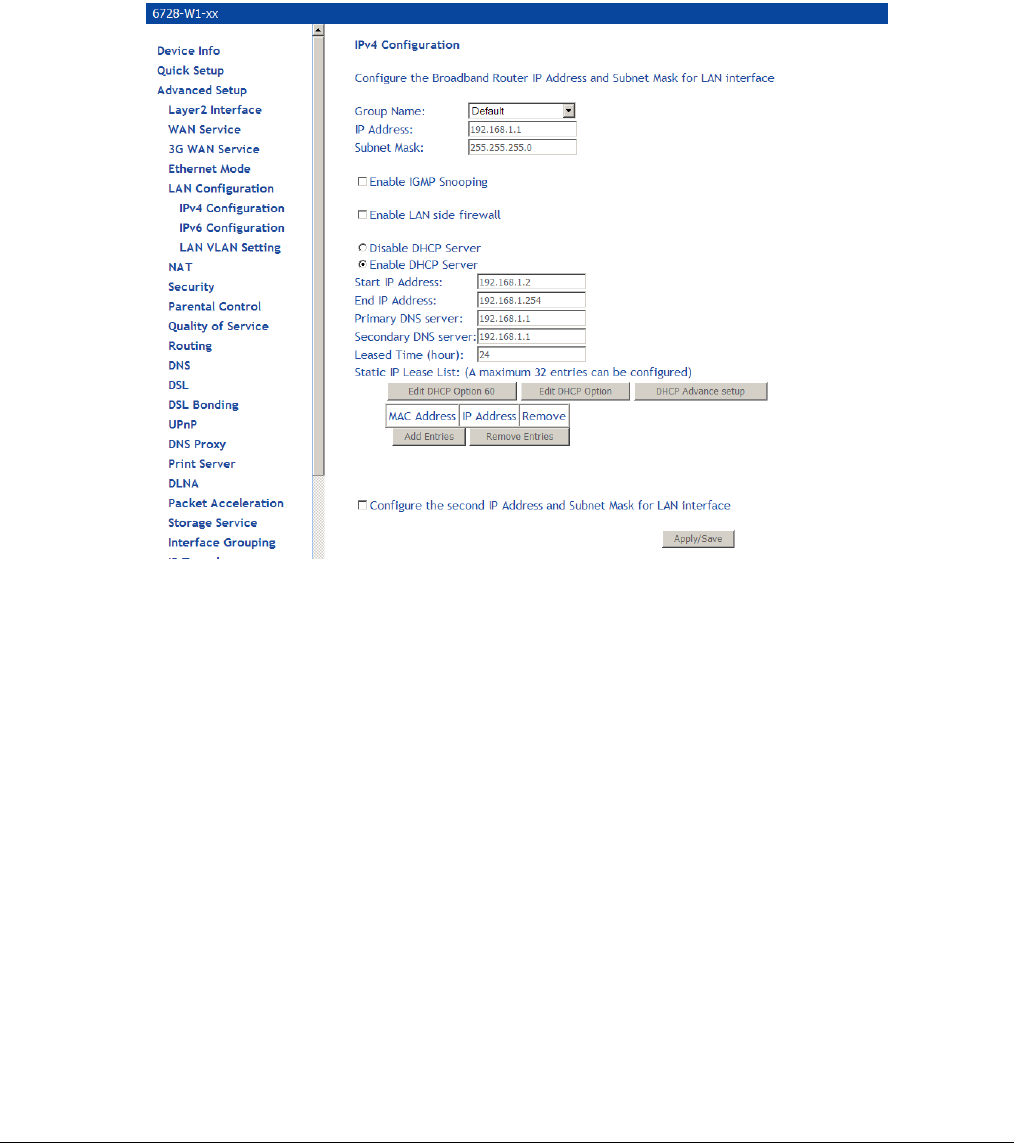
66xx/67xx Router Users Guide 76
LAN Local Area Network (LAN) Setup
The 6718 may be configured for IPv4 or IPv6.
IPv4 Configuration
You can configure the DSL Gateway IP address and Subnet Mask for the LAN interface to
correspond to your LAN’s IP Subnet.
Note: Changing the IP address here may cause your browser to be disconnected from the
modem. You will need to set your PC to the same subnet as the modem’s IP address to access
the gateway again.
• Group Name: Select a Group Name. The Group Name is created in the Interface
Grouping screen.
• IP Address—Specify an IP address for the selected Group. The default address of
192.168.1.1 is given to the first group. The default address of 192.168.2.1 is given to the
second group and so on for additional groups.
• Subnet Mask—Specify the netmask for the LAN interface.
• IGMP snooping—with IGMP snooping enabled, the gateway will snoop IGMP packets
and record the information so that it can send packets to the LAN ports. This avoids
flooding the LAN ports with multicast traffic.
Select Standard Mode or Blocking Mode.
• DHCP—If the selected group is associated with a routed WAN interface, the DHCP
option is displayed. The option is not displayed for groups associated with a bridge WAN
interface.
If you want the DHCP server to automatically assign IP addresses, enable the DHCP
server and enter the range of IP addresses that the DHCP server can assign to your
computers. Disable the DHCP server if you would like to manually assign IP addresses.
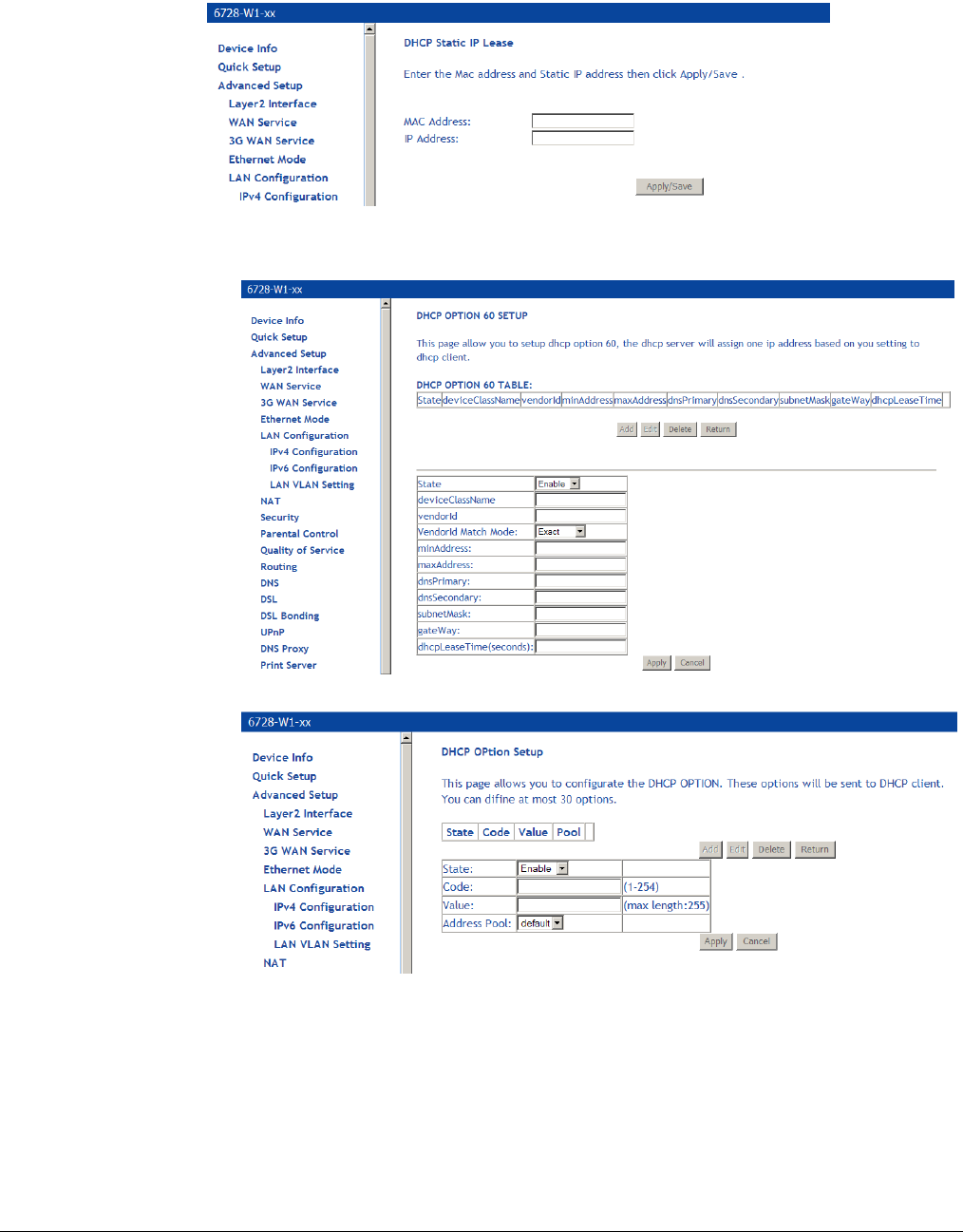
66xx/67xx Router Users Guide 77
• Static IP Lease list – you can configure the DHCP server to set aside up to 32 static IP
addresses based on the MAC addresses of the device connected to the gateway by
clicking the Add Entries button.
The static IP addresses may be enhanced with the following options:
• Edit DHCP Option 60 —
• Edit DHCP Option —
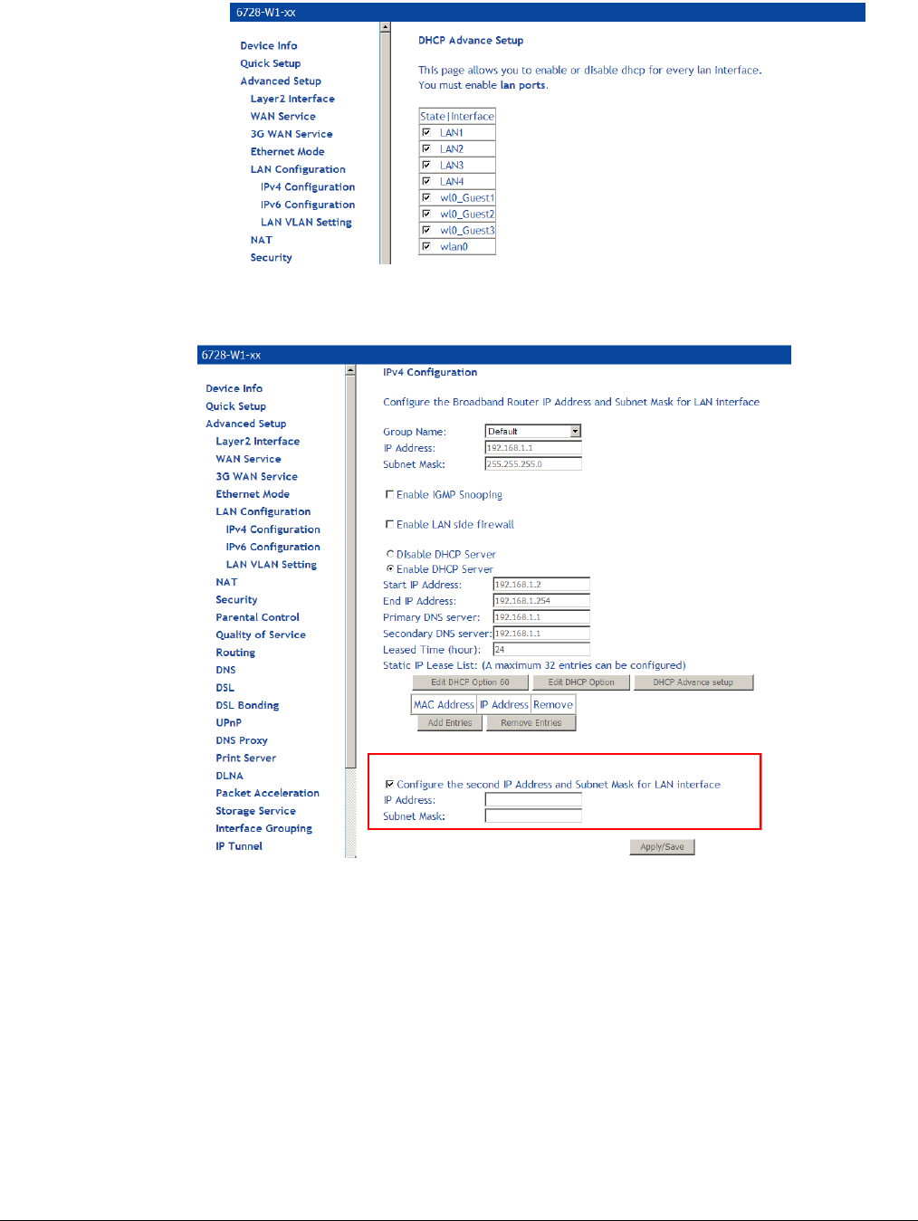
66xx/67xx Router Users Guide 78
• DHCP Advance setup —
• You may be able to assign a second IP address for the gateway. To do that, click the
check box Configure the second IP Address and enter the IP address and subnet
mask.
To remove the Static IP address, click the check box next to the MAC address and click Remove
Entries.
Click the Apply/Save button to save the LAN configuration data.
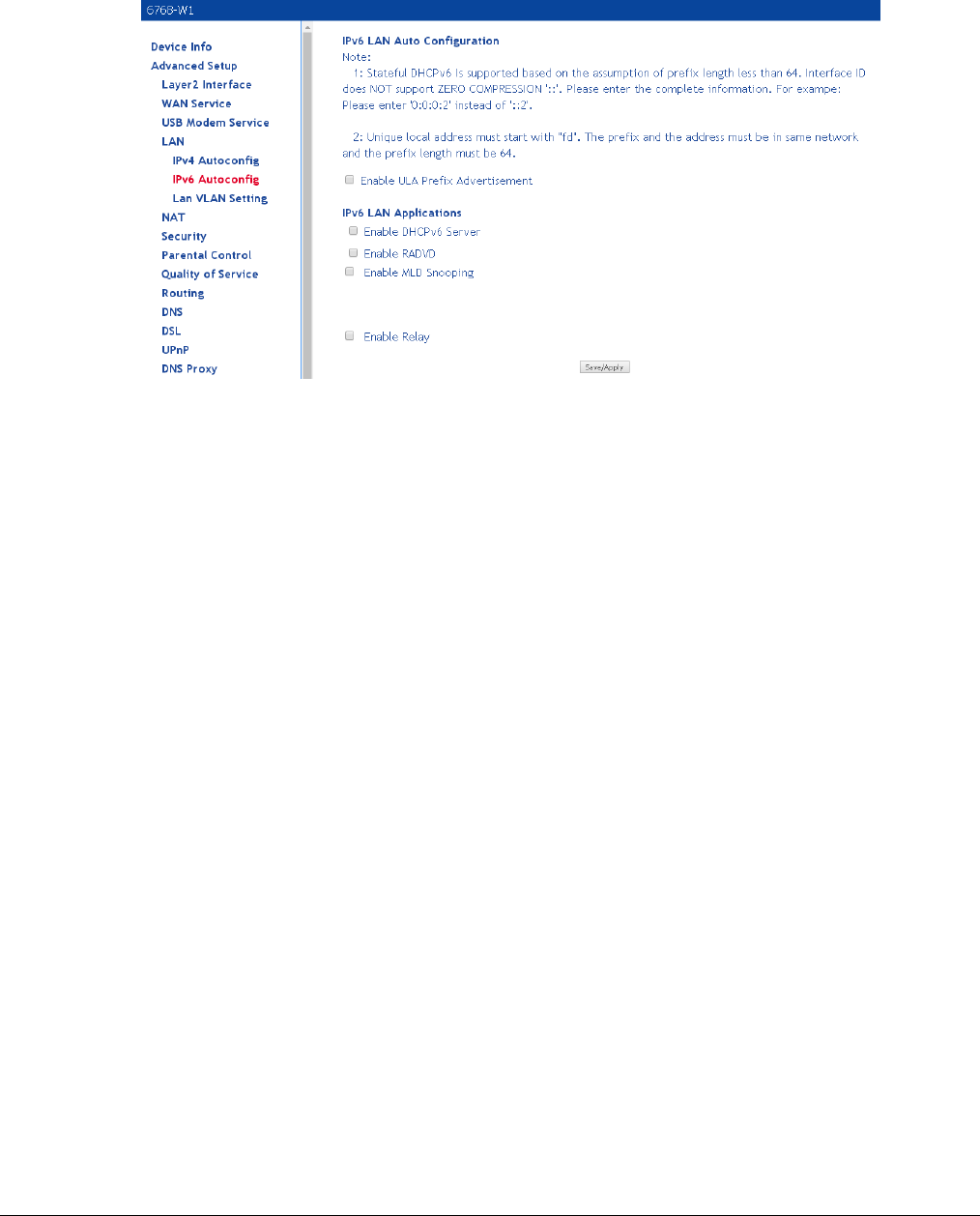
66xx/67xx Router Users Guide 79
IPv6 Configuration
In this screen, you can set an IP v6 address for the DSL IPv6 gateway, enable the DHCPv6
server, enable RADVD and enable the MLD snooping function.
• Enable ULA Prefix Advertisement: Advertises the Unique Local Address (ULA). ULAs are
used for private networks.
• Enable DHCPv6 Server: Enables the IPv6 DHCP server.
• Enable RADVD: The gateway advertisement daemon (RADVD) is run by Linux or BSD
systems acting as IPv6 routers. It sends router advertisement messages, specified by
RFC2461, to a local Ethernet LAN periodically and when requested by a node sending a
router solicitation message. These messages are required for IPv6 stateless auto-
configuration.
• Enable MLD Snooping: Multicast Listener Discovery Snooping (MLD Snooping) is an IPv6
multicast constraining mechanism that runs on Layer 2 devices to manage and control IPv6
multicast groups. By analyzing received MLD messages, a Layer 2 device running MLD
Snooping establishes mappings between ports and multicast MAC addresses and forwards
IPv6 multicast data based on these mappings.
• Enable Relay: When the unit is used as a relay agent for the DHCPv6 server
Click the Apply/Save button to save the IPv6 auto-configuration data.
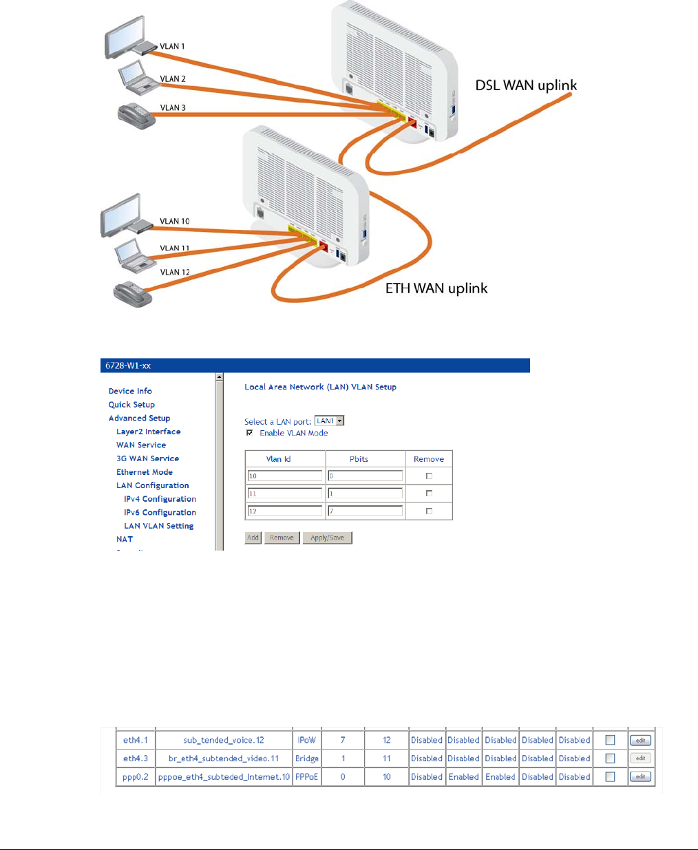
66xx/67xx Router Users Guide 80
LAN VLAN Setup
The LAN VLAN setup provides a mechanism for subtending another 6xxx from a 6xxx. Using an
Ethernet link from the downstream device connected to an Ethernet port, you need to instruct the
6xxx to forward
On the subtended device set it up to use the LAN1 interface for the VLANs.
Following this example, you could set up the interfaces in this way:
the voice service is using the IPoE WAN service on VLAN 12 with 802.1P set to 7 (highest
priority)
the video service is using a bridge WAN service on VLAN 11 witth 802.P set to 1
internet service is using PPPoE WAN service on VLAN 10 with no setting on 801.1P (lowest
priority)
The interfaces from the example, as displayed in the Device Info | Summary screen:
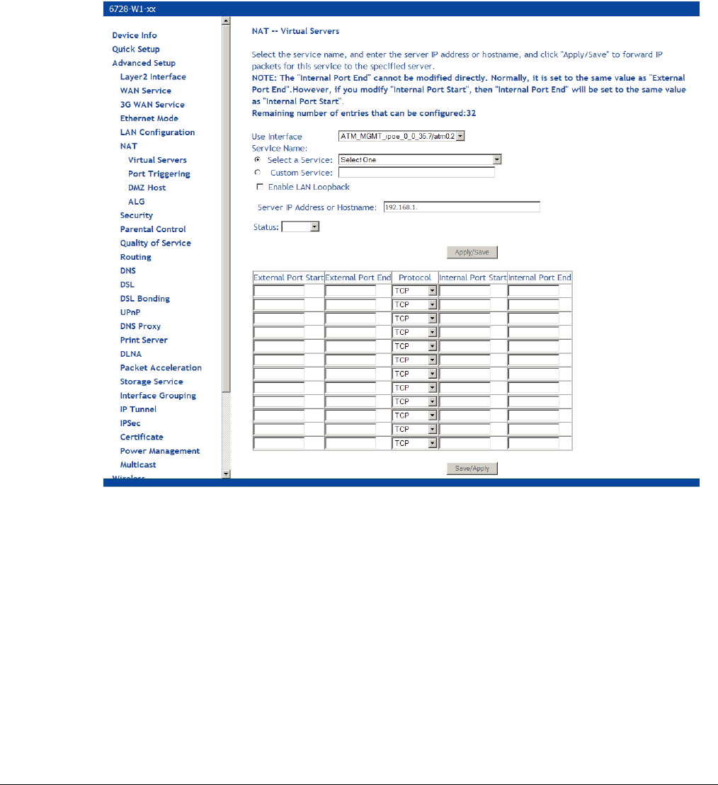
66xx/67xx Router Users Guide 81
NAT
You can configure Virtual Servers, Port Triggering, and DMZ Host when NAT (Network Address
Translation) is enabled.
Virtual Servers
A virtual server allows you to direct incoming traffic from the WAN side to a specific IP address on
the LAN side. The following figure shows the screen that allows you to configure your virtual
server(s).
To direct incoming traffic from a service (or other server):
1. Click Add to configure a virtual server.
2. Either select a service (by using the Select a Service dropdown) or select a custom server
(by entering the IP address of the server in the Custom Server text box).
You can select a Service or make a new one.
3. Enter the IP address of the LAN side PC in the Server IP Address text box.
4. Click Save / Apply to submit the configuration.
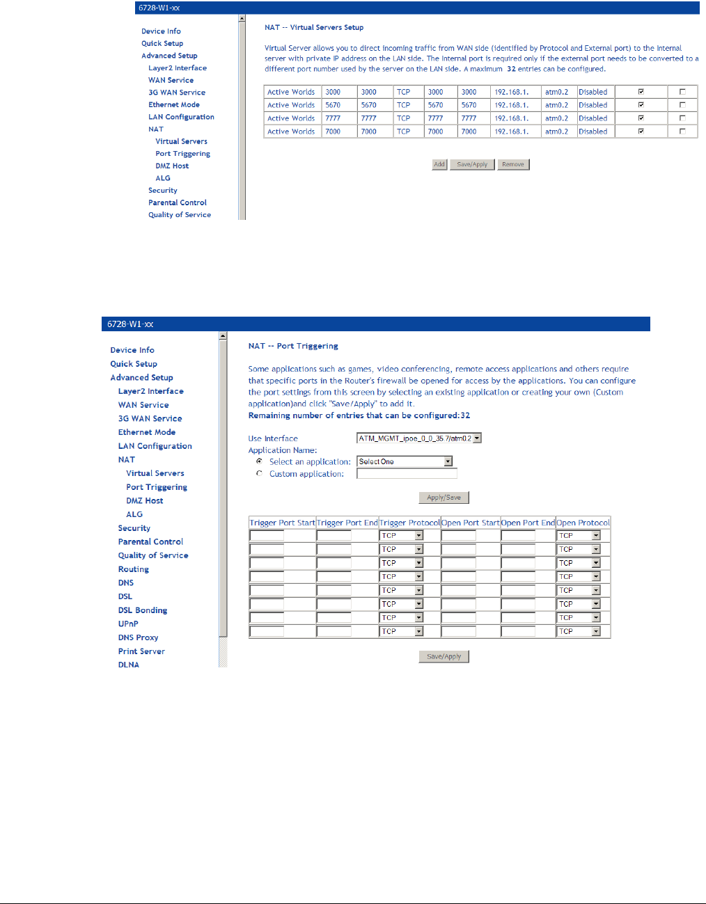
66xx/67xx Router Users Guide 82
The NAT – Virtual Servers Setup screen appears after you save your selection. To add
additional virtual servers, click Add. If you need to remove any of the server names, select
the check box for the item and click Remove.
Port Triggering
Click Add to add Port Triggering to your Internet application.
The NAT – Port Triggering screen appears when you click Add allowing you to select the
application that you want to set the port settings for. After a selection has been made, click Save /
Apply to save your settings.
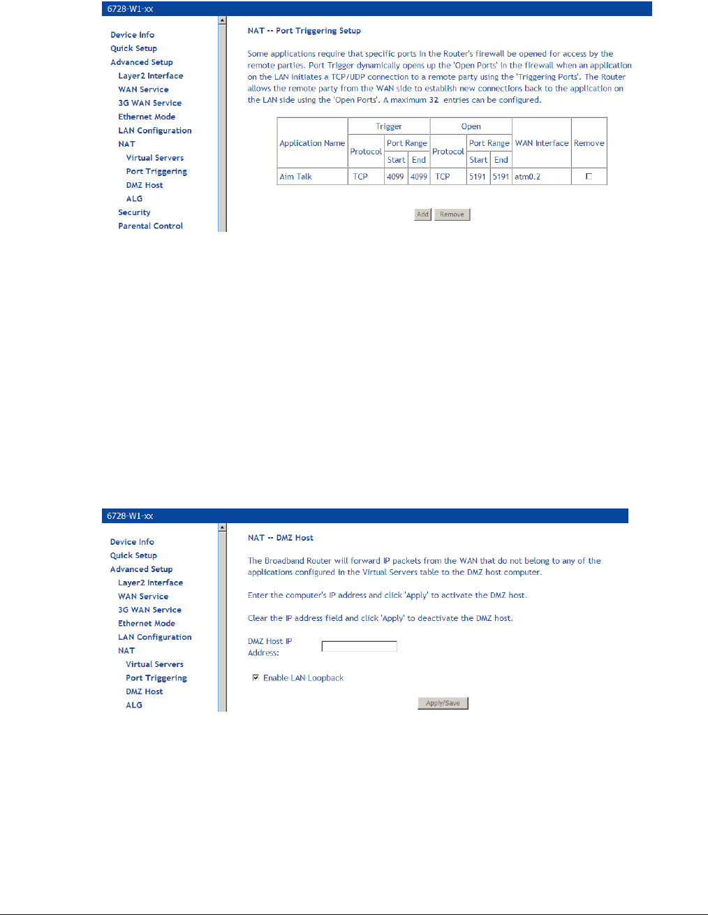
66xx/67xx Router Users Guide 83
The NAT – Port Triggering Setup screen appears after you save your selections. You will be
able to add or remove selections made by clicking on the Add and Remove buttons.
DMZ Host
Normally, you do not want hosts on your gateway’s network to be accessible from the internet.
But if you want set up a service (such as an FTP or a web server or a Web) that must be
accessed from outside your network, you can set up DMZ (de-militarized zone) host. The DMZ
host will accept IP traffic from the Internet.
Set the IP address of the PC to be DMZ host, so that the DMZ host will not be blocked by firewall.
LAN loopback maps the WAN IP address to the local server’s IP address, so that locally hosted
servers on LAN side subnets or the DMZ have access to or from the Internet.
You can define the IP address of the DMZ Host on this screen. Enter the IP address and click
Save / Apply.
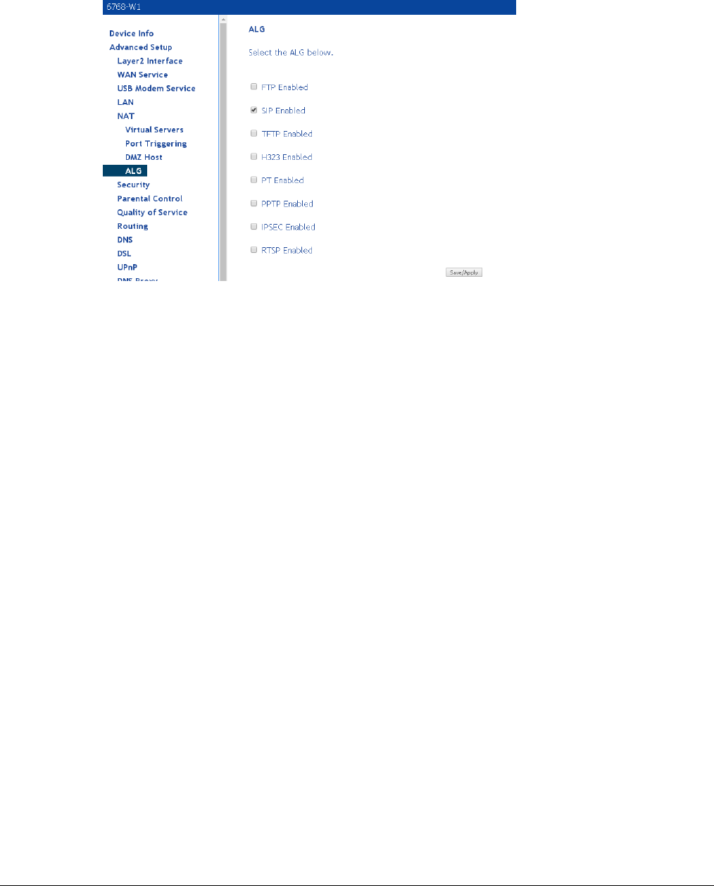
66xx/67xx Router Users Guide 84
ALG
ALG, Application Layer Gateway can be used to allow firewall traversal with SIP. To enable voice
packets to successfully pass through firewalls and NAT, click on the SIP enabled checkbox.
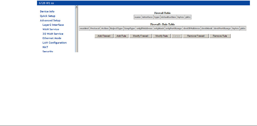
66xx/67xx Router Users Guide 85
Security
Firewall
Note: For security reasons, firewall options can be configured only from the LAN side of the
router.
Firewalls can prevent unexpected traffic on the Internet from your host on the LAN.
To add a firewall:
1. On the Security | Firewall screen, click Add Firewall.
2. In the name text box, enter a name for the firewall.l
3. Select the interface and whether this will be for ingress (type: IN) or egress (type: OUT).
4. Select the action when the rules are met from the defaultaction dropdown to Permit the
packet or Drop the packet.
5. Click Save&Apply.
6. Add rule(s) as described below)
To add a rule:
1. Select the firewall from the Firewall Table (the selected firewall is highlighted in red.)
2. Click Add Rule.
3. Define the rule from the options listed (descriptions below).
4. Click Save&Apply.
A firewall will have a number of rules to define the item to match.
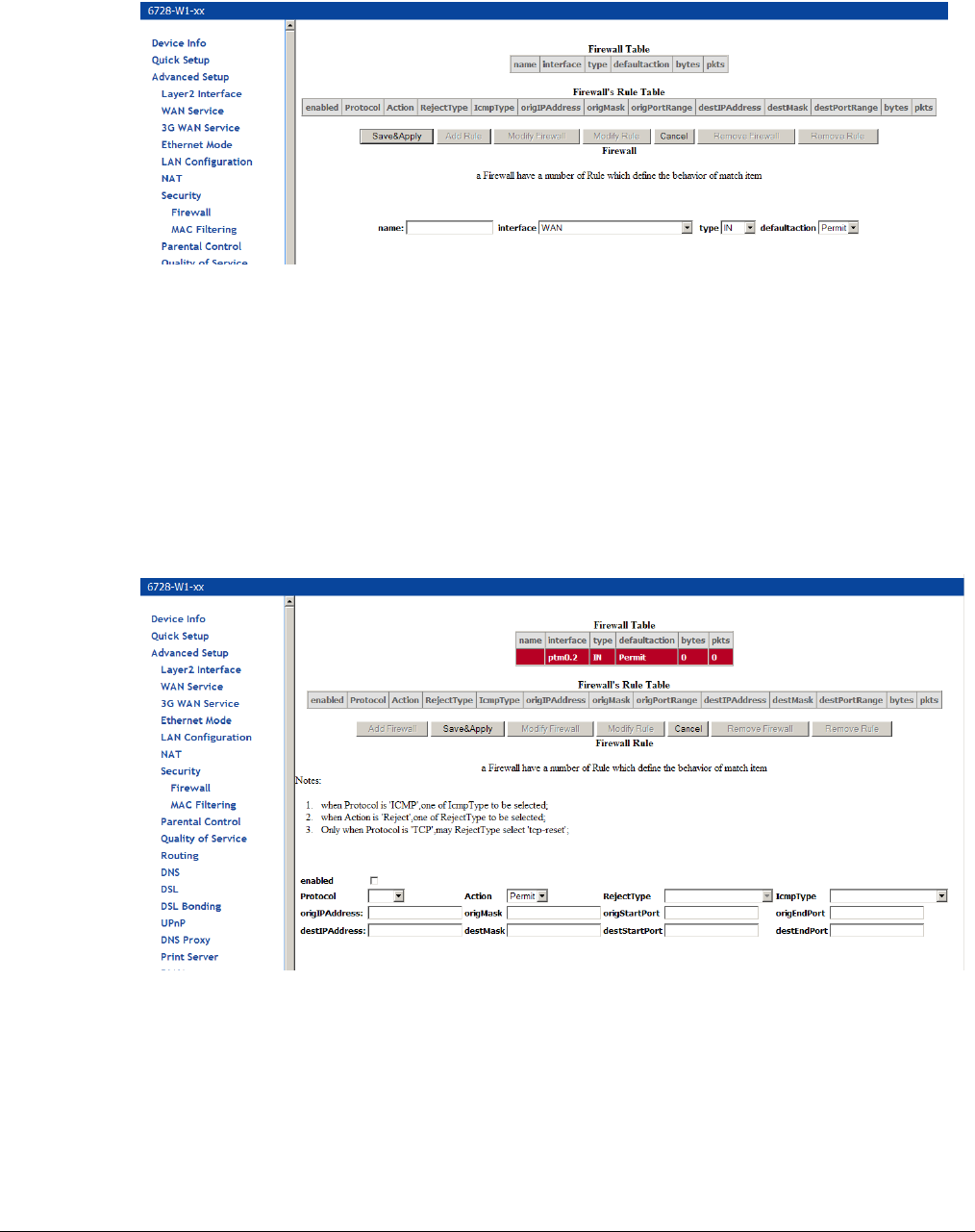
66xx/67xx Router Users Guide 86
Add a firewall
Click the Add Firewall button to add a firewall.
Name: The name of firewall.
Interface: Select WAN or mobile.
Type: Select IN or OUT.
Default Action: Select Permit or Drop.
Add a rule
Click the Add Rule button to add a rule to a firewall.
Rule options
Enabled: Select to enable the firewall rule.
Protocol: You can select UDP, TCP, or ICMP from the drop-down list.
Action: You can select Permit, Drop, or Reject from the drop-down list.
RejectType: You can select the reject type, when you select Reject as the action.
IcmpType: You can select the type of ICMP packet, when you select ICMP as the protocol.
(Displayed if ICMP is

66xx/67xx Router Users Guide 87
origIPAddress: The original IP address.
origMask: The original subnet mask.
origStartPort: The original start port.
origEndPort: The original end port.
destIPAddress: The destination IP address.
destMask: The destination subnet mask.
destStartPort: The destination start port.
destEndPort: The destination end port.
After defining the rule, click Save&Apply to save and activate the rule.
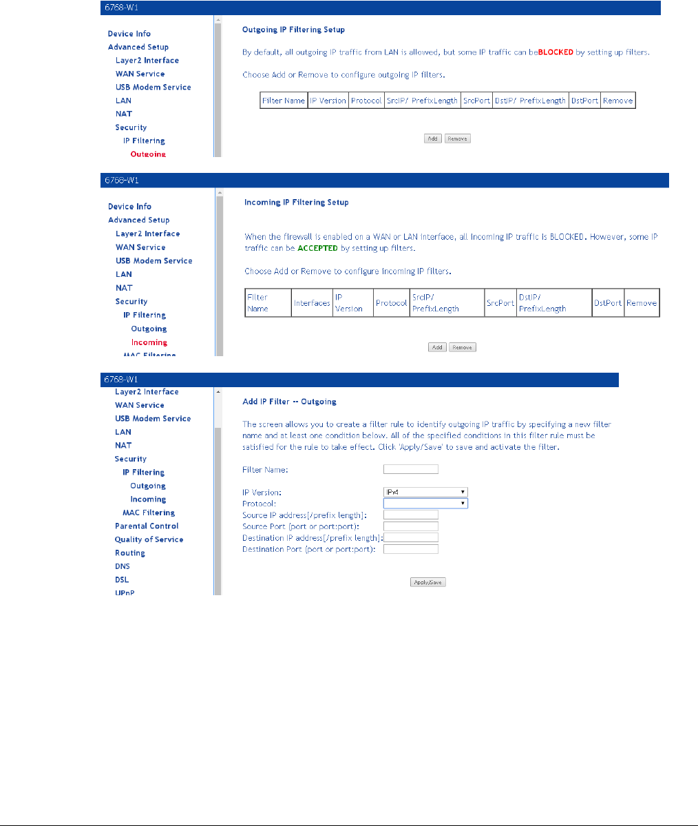
66xx/67xx Router Users Guide 88
IP Filtering
IP filters provide the mechanism for white listing (only defined xxxx are allowed) or blacklisting
(only defined xxxx are blocked) on ingress (IN) or egress (OUT) of an interface.
Some models use the Firewall screen. Others use the IP Filtering, Outgoing or Incoming screens.
The filter type (Outgoing interface blocking in this example) is defined in the firewall rule.
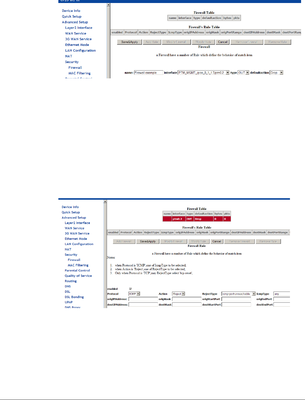
66xx/67xx Router Users Guide 89
1. In the Firewall screen, click Add Firewall and then enter a name in the name text box
2. Select the interface from the interface dropdown
3. Select OUT from the type dropdown
4. Select Drop from the default action dropdown
5. Click Save & Apply
The new rule will be displayed in red in the Firewall table
6. click Add Rule
7. Enter a check in the enabled checkbox
8. Define the rule
The text boxes define the information which will be used to identify the filter (IP address,
mask, Start Port or End Port — whether source or destination). If the field is left empty that
filter is not used for the filtering rule.
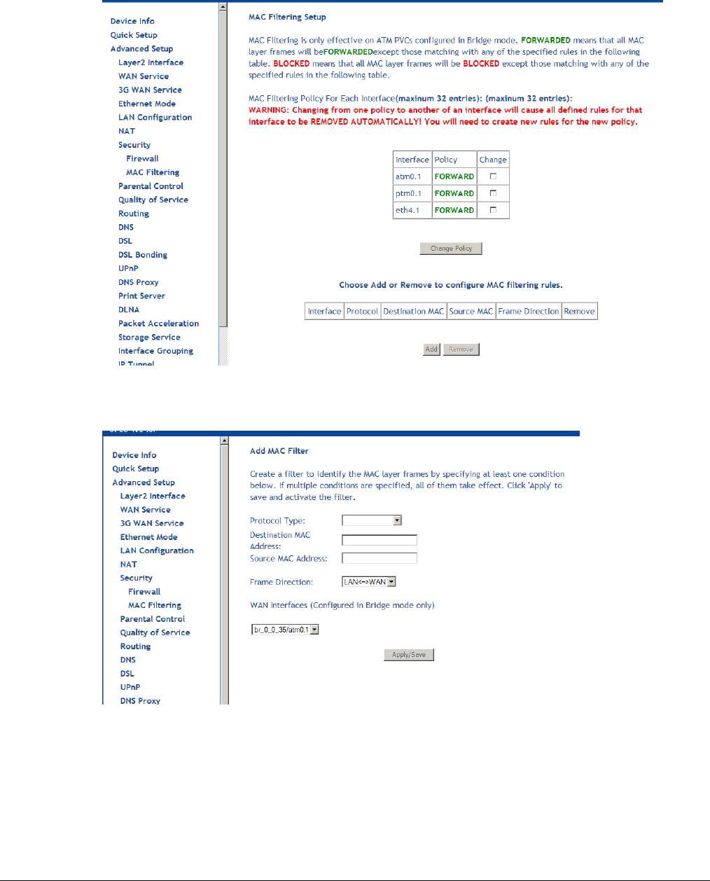
66xx/67xx Router Users Guide 90
MAC Filtering
MAC filtering is used over bridges to forward or block traffic by MAC address. You can change
the policy or add settings to the MAC filtering table in the MAC Filtering Setup screen.
To add a setting to the MAC filtering table, then click Add to access the Add MAC Filter screen,
then configure the MAC filter.
• Protocol type: Type of protocol to filter.
• PPPoE
• IPv4
• IPv6
• AppleTalk
• IPX
• NetBEUI
• IGMP
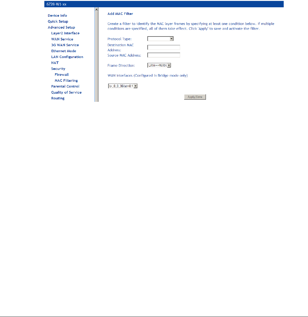
66xx/67xx Router Users Guide 91
• Destination MAC Address: the destination MAC address you want to filter
• Source MAC Address: define the source MAC address
• Frame Direction: You can define the direction of the filter. Options are
• LAN TO WAN and WAN TO LAN
• WAN to LAN
• LAN to WAN
• WAN Interfaces: defines the WAN interface for this filter. This drop down list will show all
the available WAN interfaces.
Click Save/Apply to save the MAC filter.
When you Save / Apply the IP filter, the MAC Filtering Setup screen appears. The MAC
Filtering Setup screen lists the MAC filters, including filters which were added from the previous
screen.
You can view, add or delete MAC filters. The Remove button appears only when you have an
existing IP filter already set up.
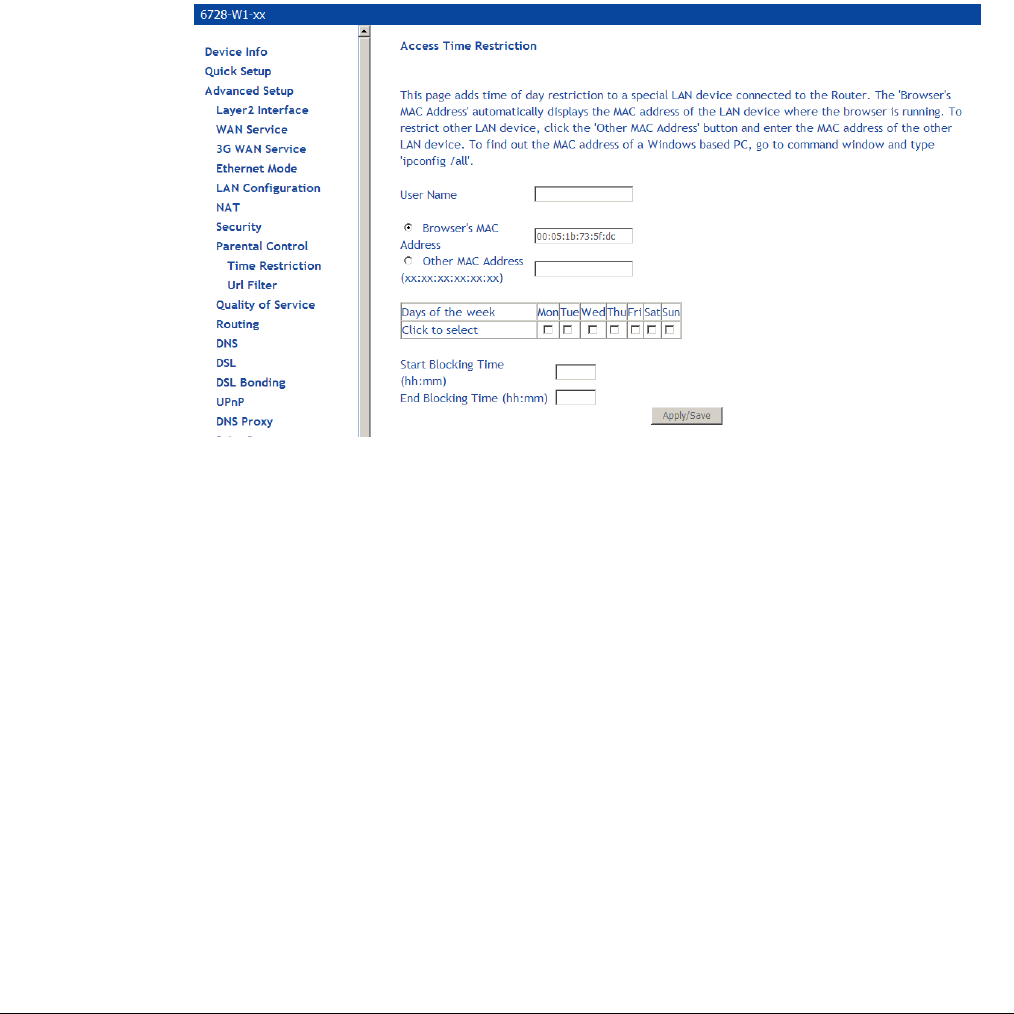
66xx/67xx Router Users Guide 92
Parental Control
Use the Parental Control feature to restrict the days and times a particular device is allowed to
access the Internet.
Time Restriction
To setup parental controls:
1. Click Parental Control.
2. Click Add to set up the restrictions.
The Access Time Restriction screen appears.
3. Enter a User Name to identify the target of the restrictions. . This is equivalent to the host
name of the IP clients (refer to the DHCP status screen check to see the host names)
4. Enter the MAC address of the network adapter to be restricted, and, optionally, another MAC
address.
5. Select the days of the week the restriction is in force.
6. Specify the start and end times the restriction is in force. Use the form hh:mm, where 23:59,
for example, is one minute before midnight.
7. Click Save / Apply to save the settings and to continue.
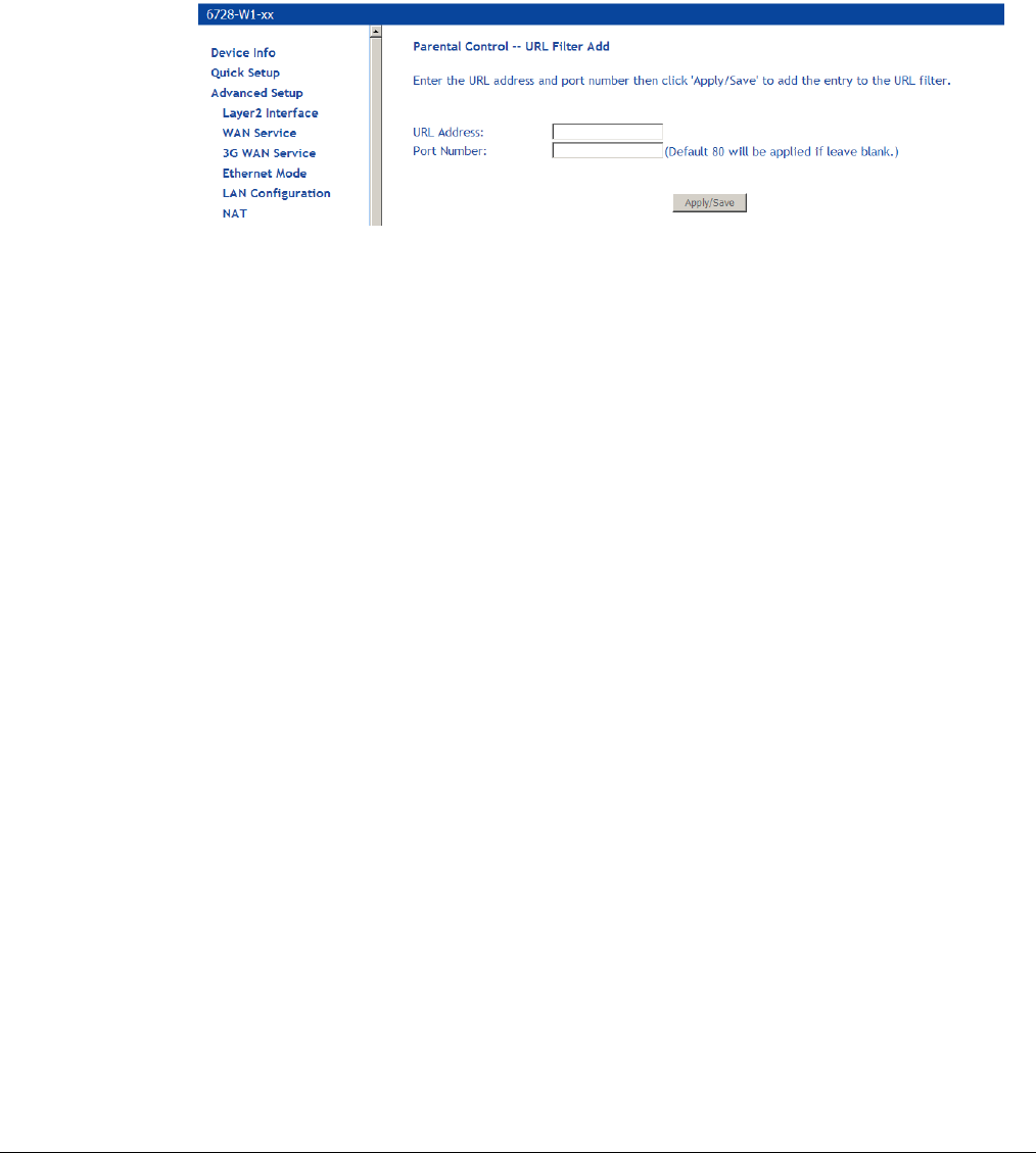
66xx/67xx Router Users Guide 93
URL Filter
Access to websites can be blocked by creating a URL filter. Two types of lists can be created,
either an exclude or include list.
1. Select the Exclude button or Include button to specify the web sites you want to block or
allow access.
2. Click Add to continue to the next screen to enter the URL address.
3. In URL Address enter the URL address; in Port Number enter the port number and click
Save / Apply.
If no port number is entered, the default 80 port will be applied. Continue this process until all
the necessary websites are entered.
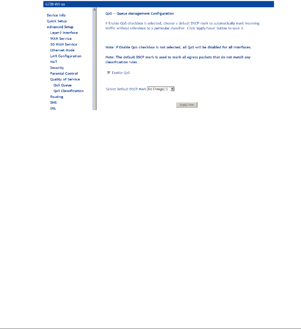
66xx/67xx Router Users Guide 94
Quality of Service
You can configure the Quality of Service to apply different priorities to traffic on the router.
Queue Config
In the QoS -- Queue Management Configuration page you can enable a queue for a network
interface. Each interface associated with QoS is allocated three queues. Lower Queue
Precedence values denote a higher priority for the queue, so “1” has higher priority than “2.”
To enable QoS:
1. From the Quality of Services page, check Enable QoS.
2. From the Select Default DSCP Mark drop down select the option as directed by your ISP.
Differentiated Services Code Point (DSCP) is a means to classify packets in the IP header of
the packet.
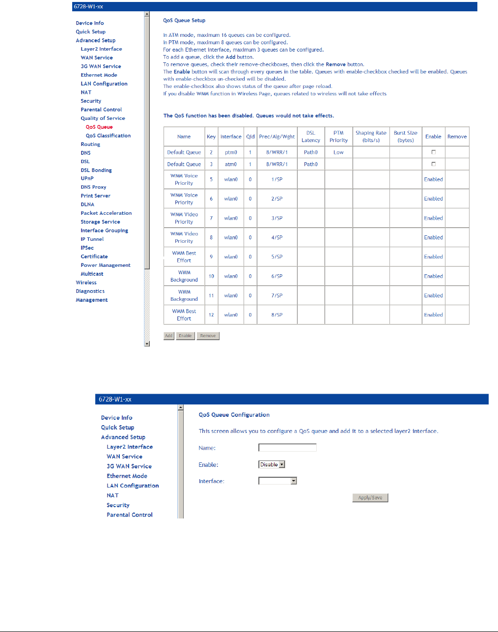
66xx/67xx Router Users Guide 95
To associate an interface with QoS:
1. From the QoS Queue Setup page, click Add.
2. In the QoS Queue Configuration page enter the name of the queue and enable the queue
by selecting Enable from the Queue Configuration Status drop down.
4. Select the interface from the Interface drop down.
5. Set the priority for the queue from the Precedence drop down
6. Click Save/Apply.
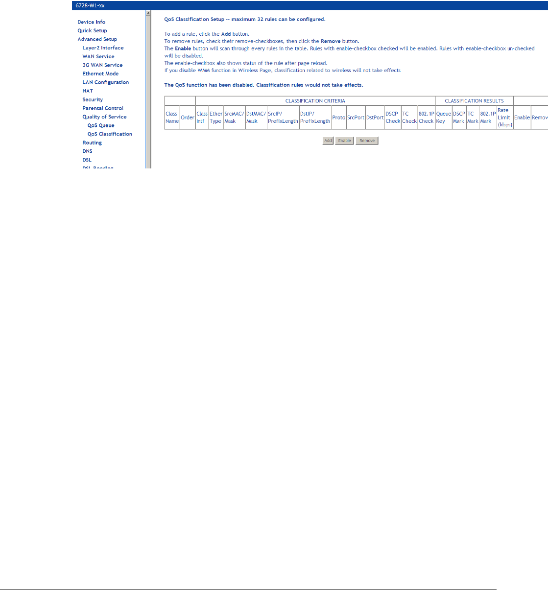
66xx/67xx Router Users Guide 96
WLAN Queue
QoS Classification
You can configure the Quality of Service to apply different priorities to traffic on the router.
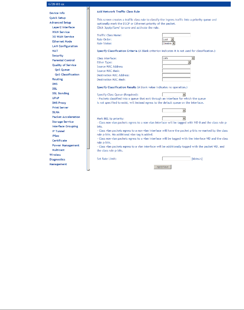
66xx/67xx Router Users Guide 97
To add a rule:
1. In the Quality of Service—QoS Classification screen, click Add.
2. In the Add Network Traffic Class Rule screen give a name to this traffic class.
3. Assign a rule order to this traffic class.
4. Enable the rule in the Rule Status.
5. Enter Security Classification Criteria:
Class Interface: The interface to apply the rule on. Depending on the class of interface
options for the traffic rule will change.
Ether Type: Type of Ethernet packet used on the interface. Depending on the Ether Type
selected, options for the traffic rule will change.
6. Enter Classification Results.
7. Click Save / Apply to save the settings.
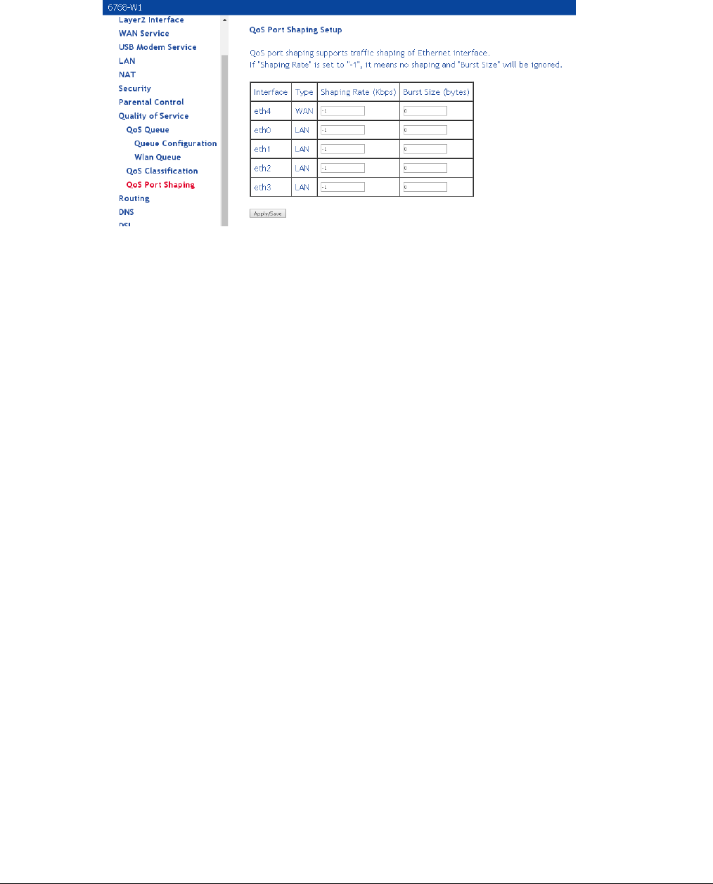
66xx/67xx Router Users Guide 98
QoS Port Shaping
Shapes the traffic on Ethernet interfaces in rate and burst size. If Shaping Rate is set to -1 then
there will be no traffic shaping and the burst size will also be ignored.
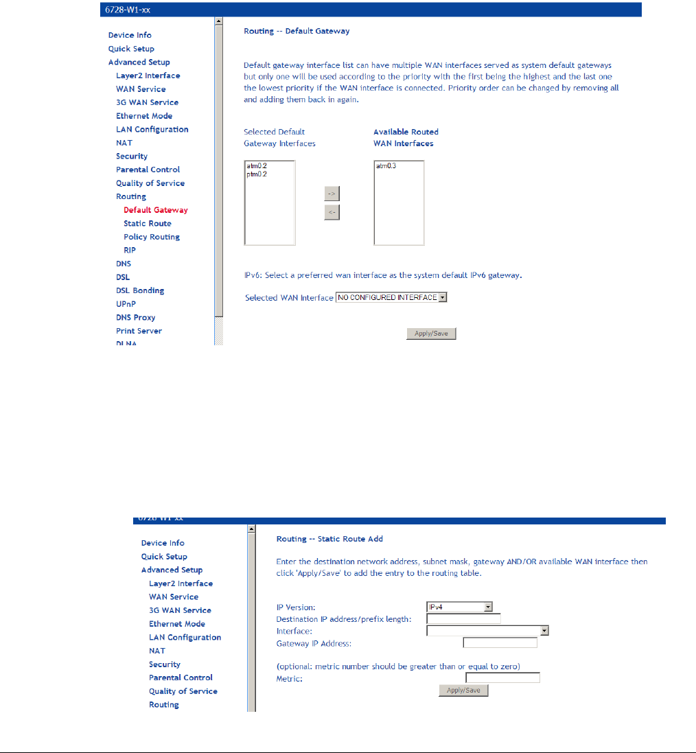
66xx/67xx Router Users Guide 99
Routing
Under the Routing heading you assign a default gateway, create a routing table (in Static Route),
create routing policy rules, and activate Routing Information Protocol (RIP) on the device.
Default Gateway
You can enable an automatic assigned default gateway on the Routing – Default Gateway
screen or specify a static default gateway. By default, the router will use an available WAN
interface as the default gateway.
If you change the automatic assigned default gateway address, you must reboot the router for the
change to take effect.
Static Route
To add a routing table use the Static Route page. A maximum of 32 entries can be added.
1. Click Add.
2. Enter the route information and then click Apply/Save.
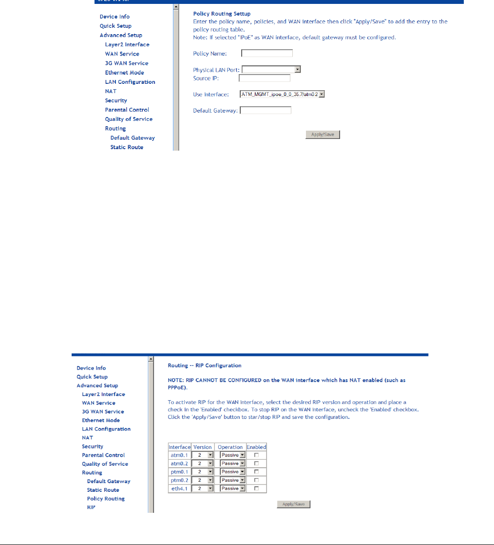
66xx/67xx Router Users Guide 100
Policy Routing
The policy routing feature allows the administrator to have more control over how packets should
flow through the modem and into their networks. The feature allows administrator to route IP
packets according to their Source Interface; Source/Destination IP address/subnets; IP Protocols;
Source/Destination Ports to specific Gateway address and/or Gateway Interfaces.
To add a policy routing rule:
1. Click Add.
2. Enter a unique name for the rule in the Policy Name text box.
3. Select the interface to associate with the rule from the Physical LAN Port drop down.
4. Specify a Source IP Address.
5. Select the interface to use in the Use Interface drop down.
6. Specify a Default Gateway.
7. Click Save/Apply.
RIP
To enable RIP on an interface, open the Routing – RIP Configuration page.
Enter the RIP configuration and then click Apply/Save.
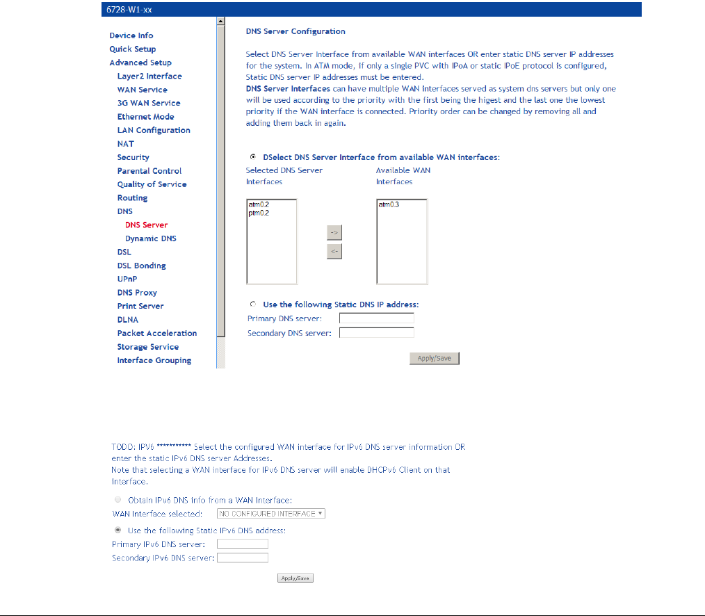
66xx/67xx Router Users Guide 101
DNS
The DNS pages configure the device to identify domain name servers (DNS) on various
interfaces and in the Dynamic DNS page to alias a dynamic IP address to a static hostname.
DNS Server
The DNS Server Configuration configures the DNS server settings for your router.
If multiple WAN interfaces are configured, you can define the priority by their position in the
Selected DNS Server Interfaces window. Top is the highest priority; bottom the lowest.
Change the priority order by removing all items from the Selected DNS Server Interfaces
window by selecting them, then clicking the right arrow button. Select the items in the priority
order, then click the left arrow to move them into the Selected DNS Server Interfaces window.
For a Static DNS IP Address, enter a primary and secondary DNS server for your router.
After you have configured the DNS settings, click Apply / Save.
For IPv6 select the configured WAN interface for the IPv6 DNS server or the static IPv6 DNS
server addresses.
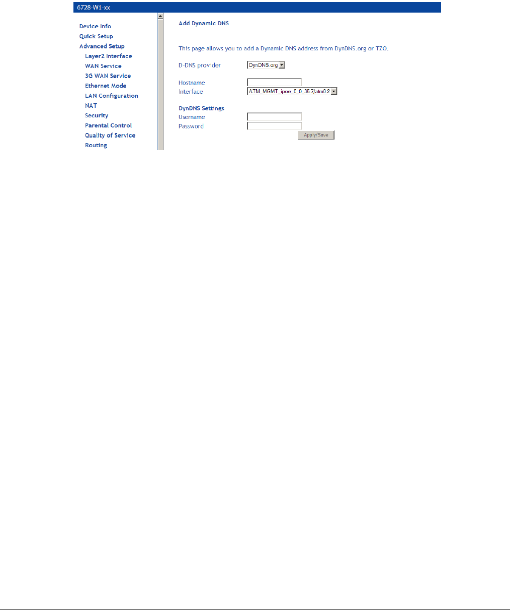
66xx/67xx Router Users Guide 102
Dynamic DNS
This screen allows you to enable dynamic DNS service.
To configure the DDNS, select the DDNS provider from the drop down list and enter the
information provided by the DDNS provider.
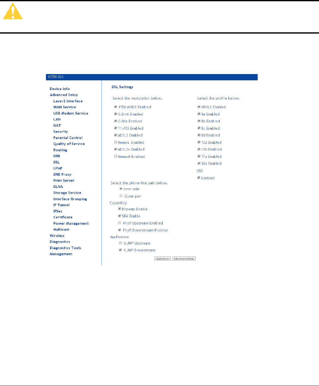
66xx/67xx Router Users Guide 103
DSL
The DSL settings page contains sections—modulation and capability—that should be specified
by your ISP. Consult with your ISP to select the correct settings for each.
Caution: Do not change DSL settings unless so directed by your ISP.
Click on Save / Apply if you are finished or click on Advanced Settings if you want to configure
more advanced settings.

66xx/67xx Router Users Guide 104
DSL parameters
When in ADSL2 mode, by default the device will detect if the upstream DSLAM supports
ADSL/PTM. If the upstream DLSAM does not support ADSL/PTM, the device will use ADSL/ATM
mode
Modulation Methods
The following modulation methods are supported:
G.dmt Enabled
G.lite Enabled
T1.413 Enabled
ADSL Enabled
Annex L Enabled
ADSL2+ Enabled
AnnexM Enabled (Disabled by default)
Do not change this setting unless so directed by your ISP.
Profile Settings
VDSL2 Enabled (must be enabled to select profiles.
8a Enabled
8b Enabled
8c Enabled
8d Enabled
12a Enabled
12b Enabled
17a Enabled
30a Enabled
Refer to the table on page 13 for which models provide Profile 30a support. For 6728, 30a is
supported only in single line mode (not bonded). If this option is selected the configuration will
change to single line mode and will require a reboot of the device.
Note: Use the cable labeled “Outer” when using single line mode.
USO
Enable or disable USO
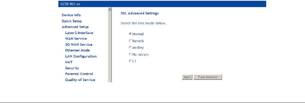
66xx/67xx Router Users Guide 105
Capability
Bitswap Enable
SRA (Seamless Rate Adaptation) Enable
SESdrop Enabled
PhyR Upstream Enabled
PhyR Downstream Enabled
Do not change these settings unless so directed by your ISP.
AuxFeature
G.INP Upstream
G.INP Downstream
Do not change these settings unless so directed by your ISP. For G.INP to work the option must
be enabled on the other side of the connection.
G.Vector is enabled by default. The configuration of G.Vector on the gateway is controlled by the
CO device.
DSL Advanced Settings
Do not change the DSL Advanced Settings unless so directed by your ISP.
To view the DSL Advanced Settings screen, click Advanced Settings button on the DSL
Settings screen.
The test mode can be selected from the DSL Advanced Settings page. There are five test modes
between the router and your ISP:
• Normal test: Puts the router in a test mode in which it only sends a Normal signal.
• Reverb test: Puts the router in a test mode in which it only sends a Reverb signal.
• Medley test: Puts the router in a test mode in which it only sends a Medley signal.
• No Retrain: In this mode the router will try to establish a connection as in normal mode, but
once the connection is up it will not retrain if the signal is lost.
• L3: Puts the router into the L3 power state.
To run a test:
1. Select a test mode and click Apply.
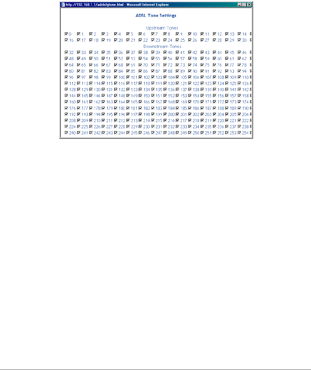
66xx/67xx Router Users Guide 106
2. Click Tone Selection.
The frequency band of VDSL is split up into 256 separate tones, each spaced 4.3125 kHz
apart. With each tone carrying separate data, the technique operates as if 256 separate
modems were running in parallel. The tone range is from 0 to 31 for upstream and from 32 to
255 for downstream. Do not change these settings unless directed by your ISP.
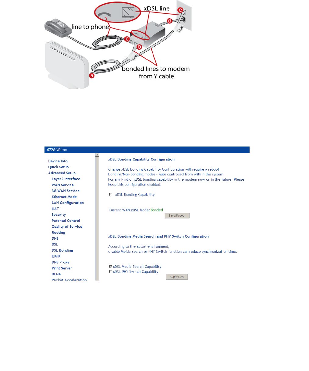
66xx/67xx Router Users Guide 107
DSL Bonding
To use bonding for the 6728-W1, use the Y cable attached as shown below. When voice service
is also delivered to the home an inline splitter may be used to provide phone service on the same
line as xDSL service.
Enter a check in the Enable DSL Bonding checkbox once the modem is properly cabled to
enable the bonding.
When Enable DSL Bonding is checked, the modem expects the WAN service to be in bonded
mode. If the WAN service does not use bonded lines, the modem will attempt to synch is single
line mode and will disable the DSL Bonding mode.
Bonding mode and xDSL profiles may be extended by the following paratmeters:
• xDSL Media Search Capability: Allows the modem to automatically scan the best xDSL
profile.
• xDSL PHY Switch Capability. Enables the modem to use single or bonded mode depending
on the CO line configuration. When the xDSL PHY Switch Capability is not selected bonding
will be determined by the xDSL Bonding Capability.
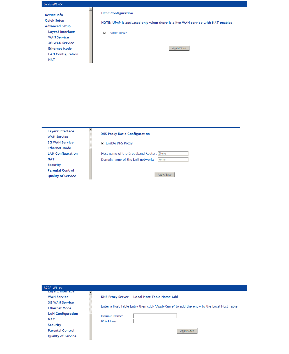
66xx/67xx Router Users Guide 108
UPnP
Universal Plug and Play (UPnP) is used to connect devices such as game consoles or printers
that are on the same subnet. Game consoles such as xBox or PS3 which requires network
connections can use UPnP to be connected to the Internet.
DNS Proxy
Basic Configuration
By default the router has a Domain Name Service (DNS) running. All DNS resolution is performed
by the router.
1. In the Host name of the Broadband Router text box enter the host name for the DNS
server to be used.
2. In the Domain name of the LAN network text box enter the domain name of the local
network.
3. Click Save / Apply.
Server Configuration
The DNS Proxy Server Configuration supports Microsoft Media Room (MMR) server. The Domain
name and the IP address of the MMR server is entered on this page and the model will provide
the IP address for the Set Top Box to boot properly.
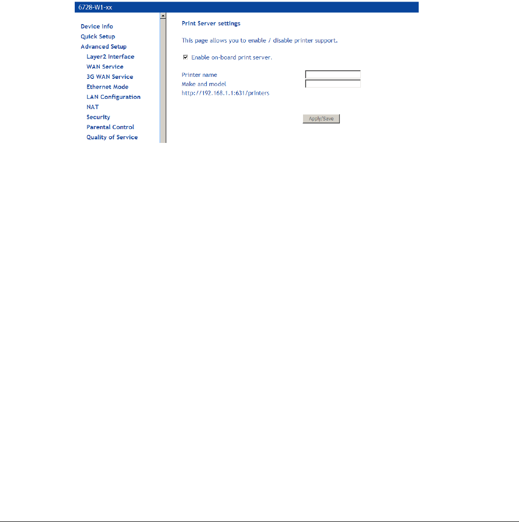
66xx/67xx Router Users Guide 109
1. On the DNS Proxy Server Configuration page click Add.
2. In the Domain name of the LAN network text box enter the domain name of the local
network.
3. In the IP Address text box enter the IP address of the Domain Name Server to add it to the
Local Host Table.
4. Click Save / Apply.
Print Server
Enable or disable a printer server on the router. This requires that you plug in a USB drive into
the USB port 2 on the router.
Adding a printer server
This section explains how to add a printer server the router for Windows 7 and Windows XP. For
other operating systems, refer the documentation for your device. When adding a printer server
for the router, use the following syntax:
http://<modem_IP_Address>:<Port ID>/printers/<Printer_Name>
Where
<modem_IP_Address> is the Modem LAN IP Address, the default IP Address is 192.168.1.1
<Port_ID>: fixed at 631
<Printer_Name> must be the same name entered in the modem Printer Server Setting screen.
Windows 7
1. In the Advanced Setup > Print Setup screen, add the printer. In this example, the printer
name is CanonMP250.
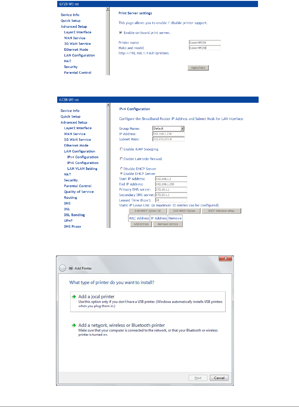
66xx/67xx Router Users Guide 110
The following example uses a router IP Address as 192.168.1.254, as shown in the LAN
Setup page. Normally, the router default IP address is 192.168.1.1
2. From the Control Panel, Hardware and Sound > Devices and Printers screen click Add a
Printer.
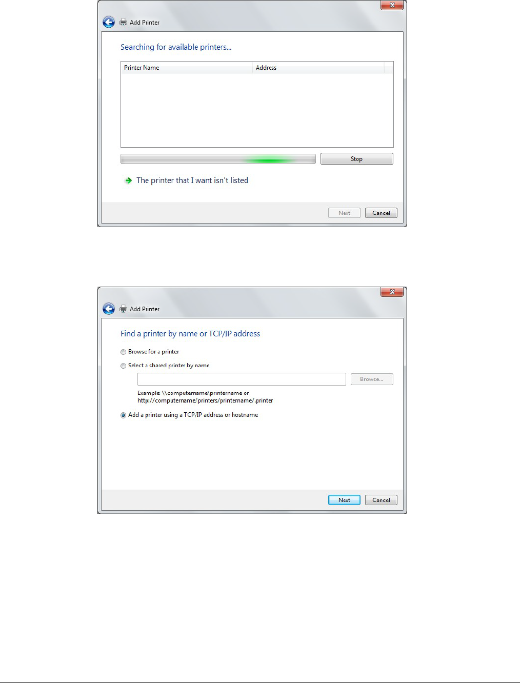
66xx/67xx Router Users Guide 111
3. Click Add a Network, Wireless or Bluetooth printer, the click Next.
4. The system will search for available printers. Click The printer that I want isn’t listed.
5. Select Add a printer using a TCP/IP address or hostname, then click Next.
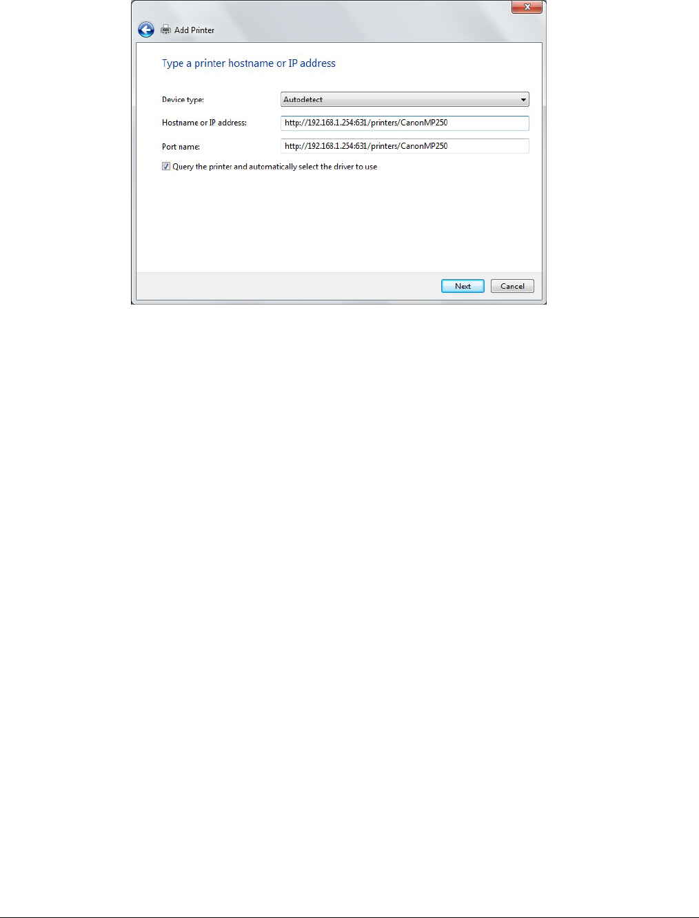
66xx/67xx Router Users Guide 112
6. Enter the address of the printer.
For example: http://192.168.1.254:631/printers/CanonMP250 and click Next.
The syntax is
http://<modem_IP_Address>:<Port ID>/printers/<Printer_Name>
Where
<modem_IP_Address> is the Modem LAN IP Address, the default IP Address is 192.168.1.1
<Port_ID>: fixed at 631
<Printer_Name> must be the same name entered in the modem Printer Server Setting as
described in Step 1.
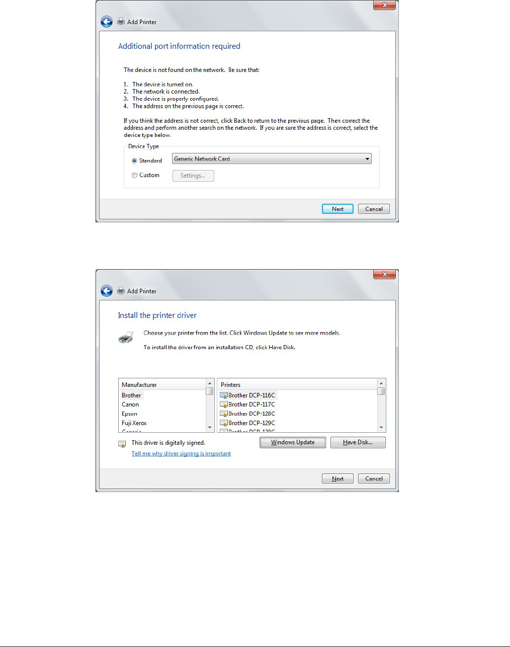
66xx/67xx Router Users Guide 113
7. If the printer cannot be found, the Additional port information required screen will appear
asking you to specify a device type. Select the type of device you are installing and click
Next.
8. In the Install the printer driver screen, select the Manufacturer of the printer and Printer
model name, then click Next.
9. Specify whether you want to share the printer and enter a printer name, if desired.
10. Click Finish.
11. Check the status of printer from Windows Control Panel, Hardware and Sound > Devices
and Printers window. Status should be Ready.
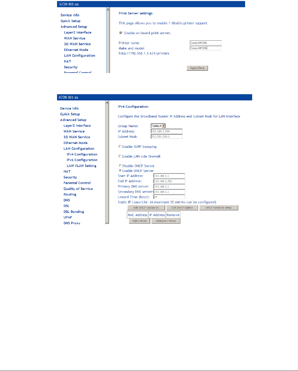
66xx/67xx Router Users Guide 114
Windows XP
1. In the Advanced Setup > Print Setup screen, add the printer. In this example, the printer
name is CanonMP250.
The following example uses a router IP Address as 192.168.1.254, as shown in the LAN
Setup page. Normally, the router default IP address is 192.168.1.1
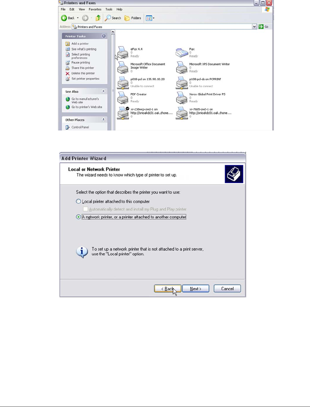
66xx/67xx Router Users Guide 115
2. Click Add a Printer from Control Panel of the Win XP computer and click Next.
3. Select Network Printer and click Next.
4. Select Connect to a printer on the Internet and enter the IP address of the printer.
For example: http://192.168.1.254:631/printers/CanonMP250 and click Next.
The syntax is
http://<modem_IP_Address>:<Port ID>/printers/<Printer_Name>
Where
<modem_IP_Address> is the Modem LAN IP Address, the default IP Address is
192.168.1.1
<Port_ID>: fixed at 631
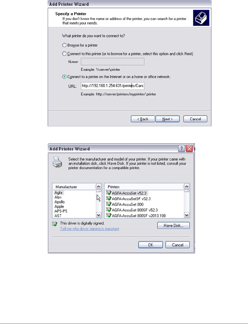
66xx/67xx Router Users Guide 116
<Printer_Name> must be the same name entered in the modem Printer Server Setting as
described in Step 1.
5. Chose the Manufacturer of the printer and Printer Model Name then click Next.
.
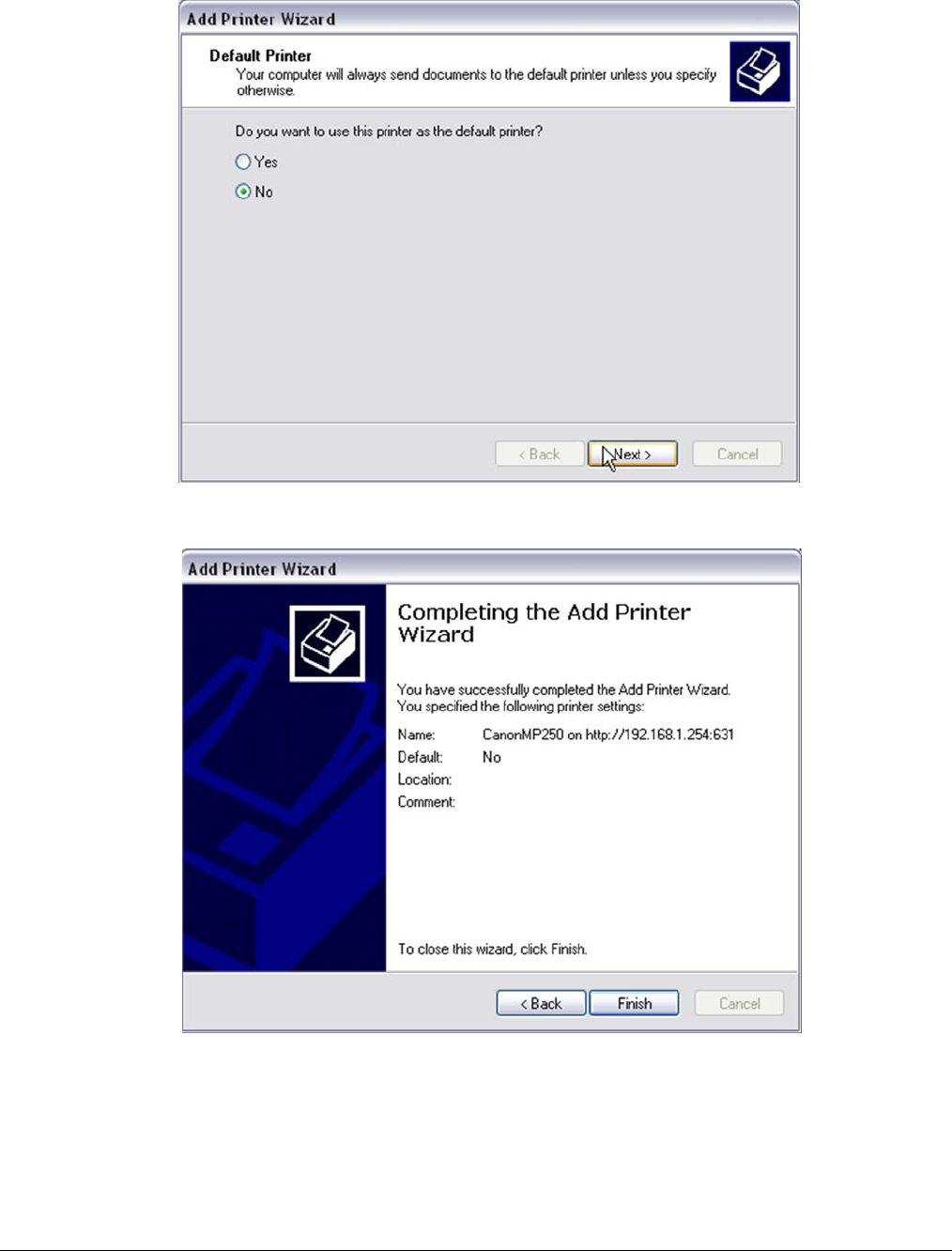
66xx/67xx Router Users Guide 117
6. Choose Yes or No for default printer setting and click Next.
7. Click Finish.
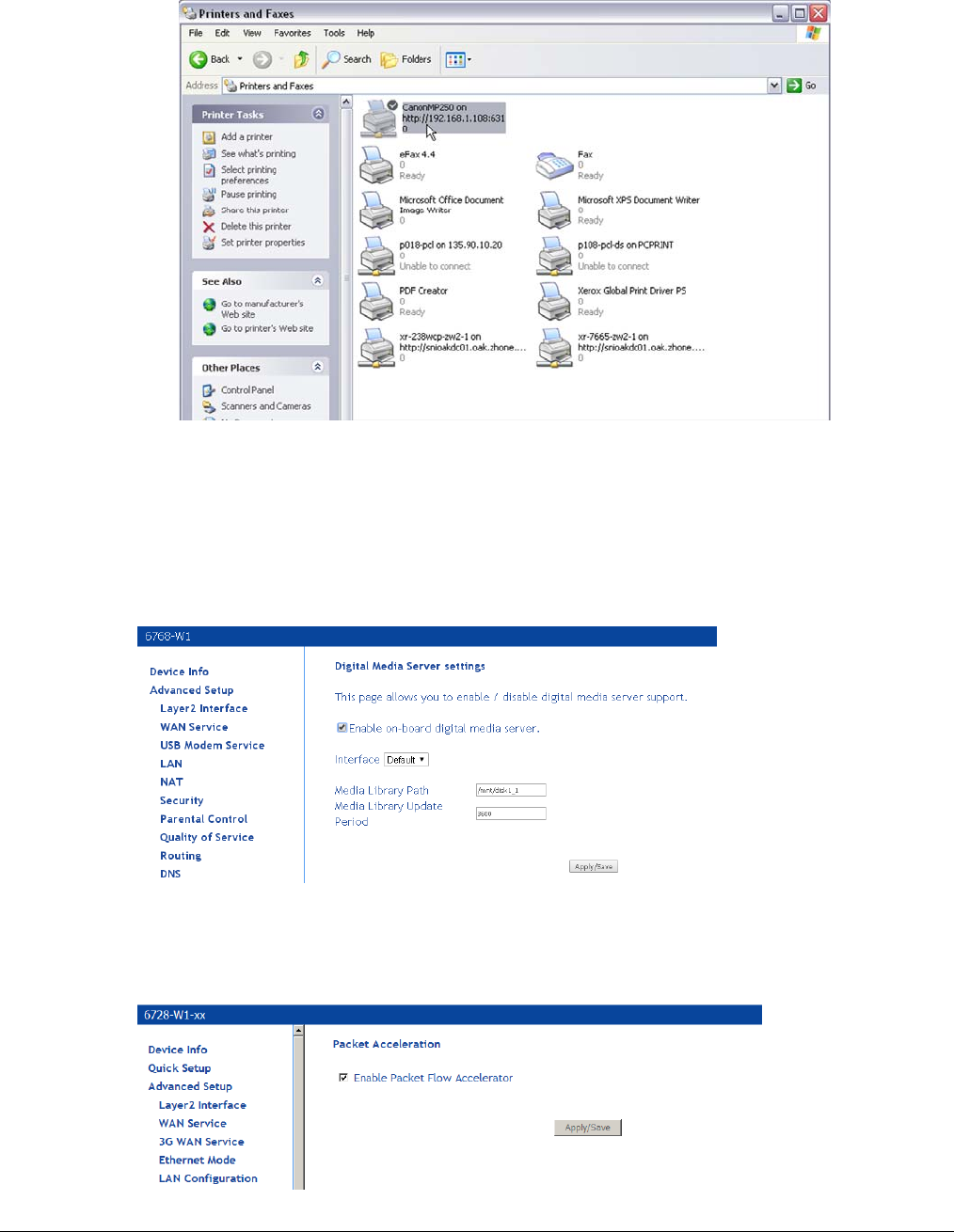
66xx/67xx Router Users Guide 118
8. Check the status of printer from Windows Control Panel, printer window. Status should be
Ready.
DLNA
Digital Living Network Alliance (DLNA) is used for sending digital media (such as music, movies,
and photos) to other DLNA devices such as a PC or an Xbox.
In this page, select the Enable on-board digital media server check box, and the following page
appears. In this page, enter the media library path to run digital media server.
Packet Acceleration
Packet Flow Accelerator provides better performance in certain scenarios.
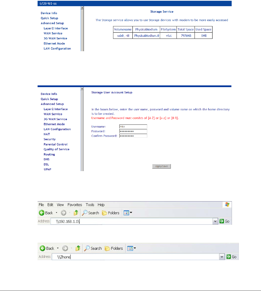
66xx/67xx Router Users Guide 119
Storage Service
This page is used to display the information of the storage device that connects to the DSL router.
Storage Device Info
Click Storage Device Info to view information about the storage device.
Note: Connect the storage device to the USB 2 port.
User Accounts
This screen configures user access to the storage device.
To access the shared storage device:
1. Open the file manager and enter the IP address of the modem
or use the DNS proxy name (default is Zhone).
The pop up screen is displayed; enter the username and password.
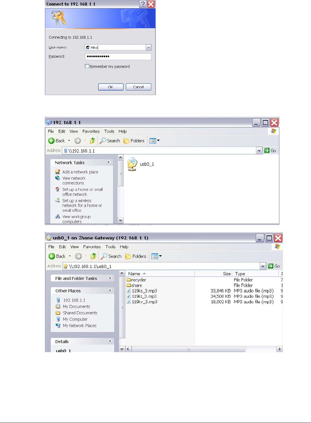
66xx/67xx Router Users Guide 120
When successfully login, you will be able to access the content of the storage device
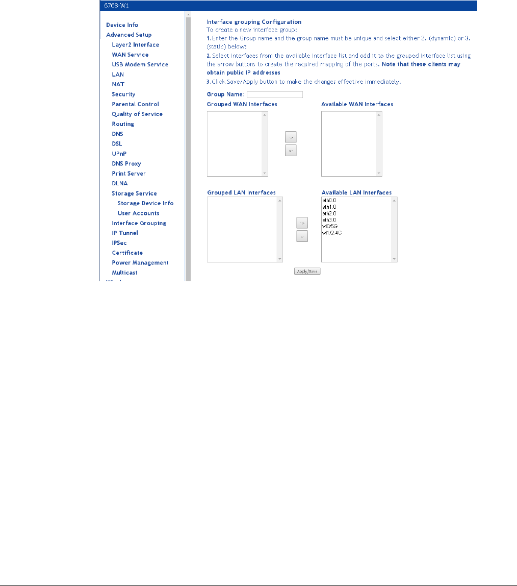
66xx/67xx Router Users Guide 121
Interface Grouping
The interface group feature allows you to open ports to allow certain Internet applications on the
WAN side to pass through the firewall and enter your LAN. To use this feature, mapping groups
should be created.
To create a new mapping group:
1. Click the Add button.
2. Enter a unique Group name.
3. Select interfaces from the available interface list and add them to the grouped interface list
using the arrow buttons to create the required mapping of the ports.
4. Click Save/Apply.
After clicking the Apply/Save button, the Interface Grouping Configuration screen
appears.
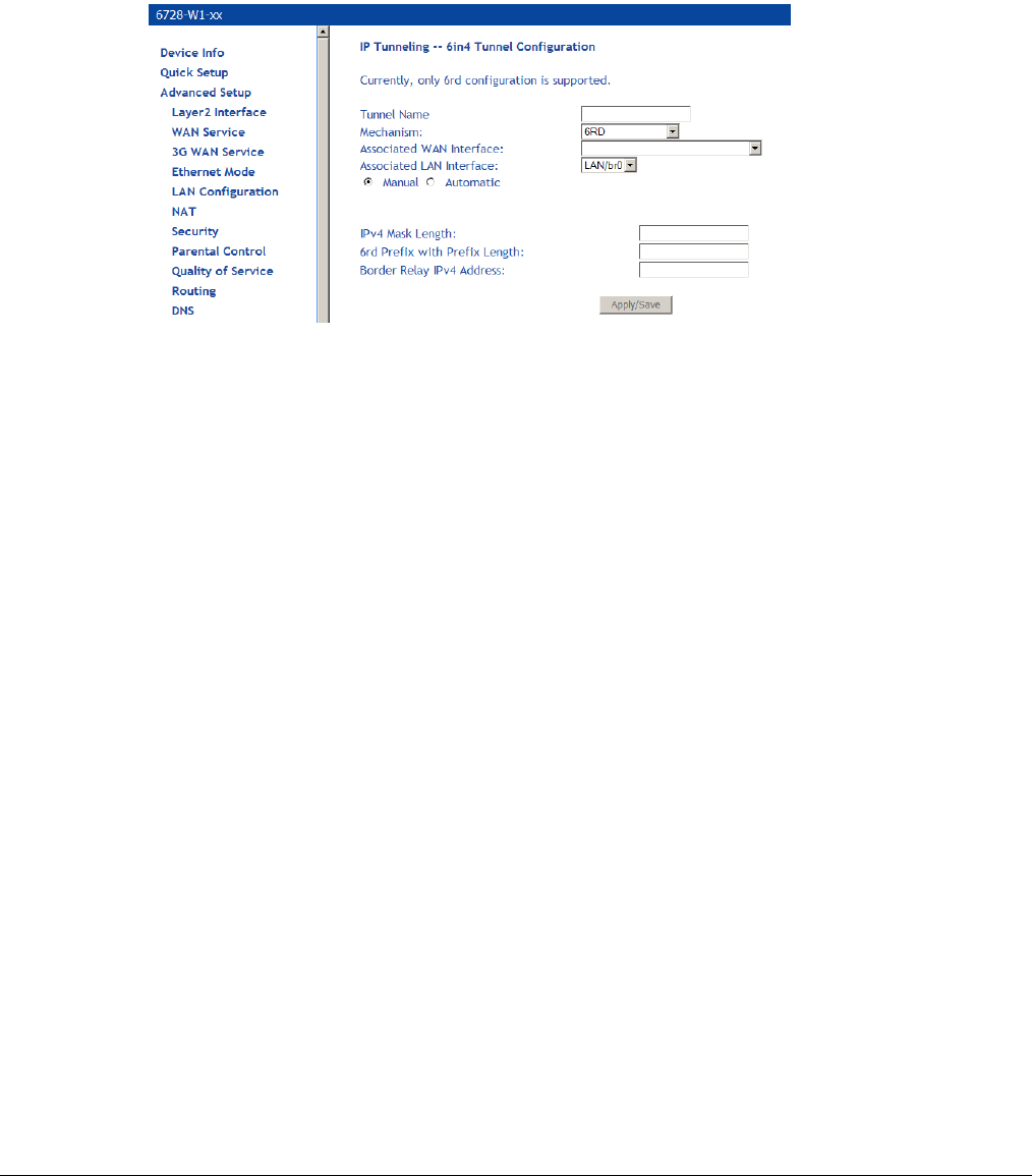
66xx/67xx Router Users Guide 122
IP Tunnel
The IP Tunnel page allows you to configure an IPv6 tunnel in an IPv4 network or an IPv4 tunnel
in an IPv6 tunnel.
IPv6inIPv4
To configure an IPv6 tunnel in a IPv4 network, select IPv6inIPv4.
• Tunnel Name: Specify a name for the tunnel.
• Mechanism: Only 6RD is supported.
• Associated WAN Interface: Select a WAN interface for the tunnel.
• Associated LAN Interface: Select a LAN interface for the tunnel.
The following parameters are only required if you select to manually configure a LAN
interface.
• IPv4 Mask Length: Specify a IPv4 mask length. Value is 0 ~ 32.
• 6rd Prefix with Prefix Length: Specify a prefix/length, such as: 2002::/64.
• Border Relay IPv4 Address: Specify an IPv4 address.

66xx/67xx Router Users Guide 123
IPv4inIPv6
To configure an IPv6 tunnel in an IPv4 network, select IPv4inIPv6.
• Tunnel Name: Specify a name for the tunnel.
• Mechanism: Only DSL-Lite is supported.
• Associated WAN Interface: Select a WAN interface for the tunnel.
• Associated LAN Interface: Select a LAN interface for the tunnel.
The following parameter is only required if you select to manually configure a LAN interface.
• Remote IPv6 Address: Specify an IPv6 address.
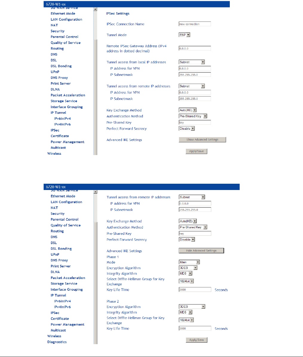
66xx/67xx Router Users Guide 124
IPSec
Internet Protocol Security (IPSec) allows you to set up secure tunnel access between two IP
addresses. Encryption and key exchange make this a secure way to access remote networks.
Contact your ISP for the necessary information to correctly configure this connection.
Click Add New Connection to access the IPSec Settings screen to enter your configurations.
The Show Advanced Settings button at the bottom of the screen provides additional encryption
settings.
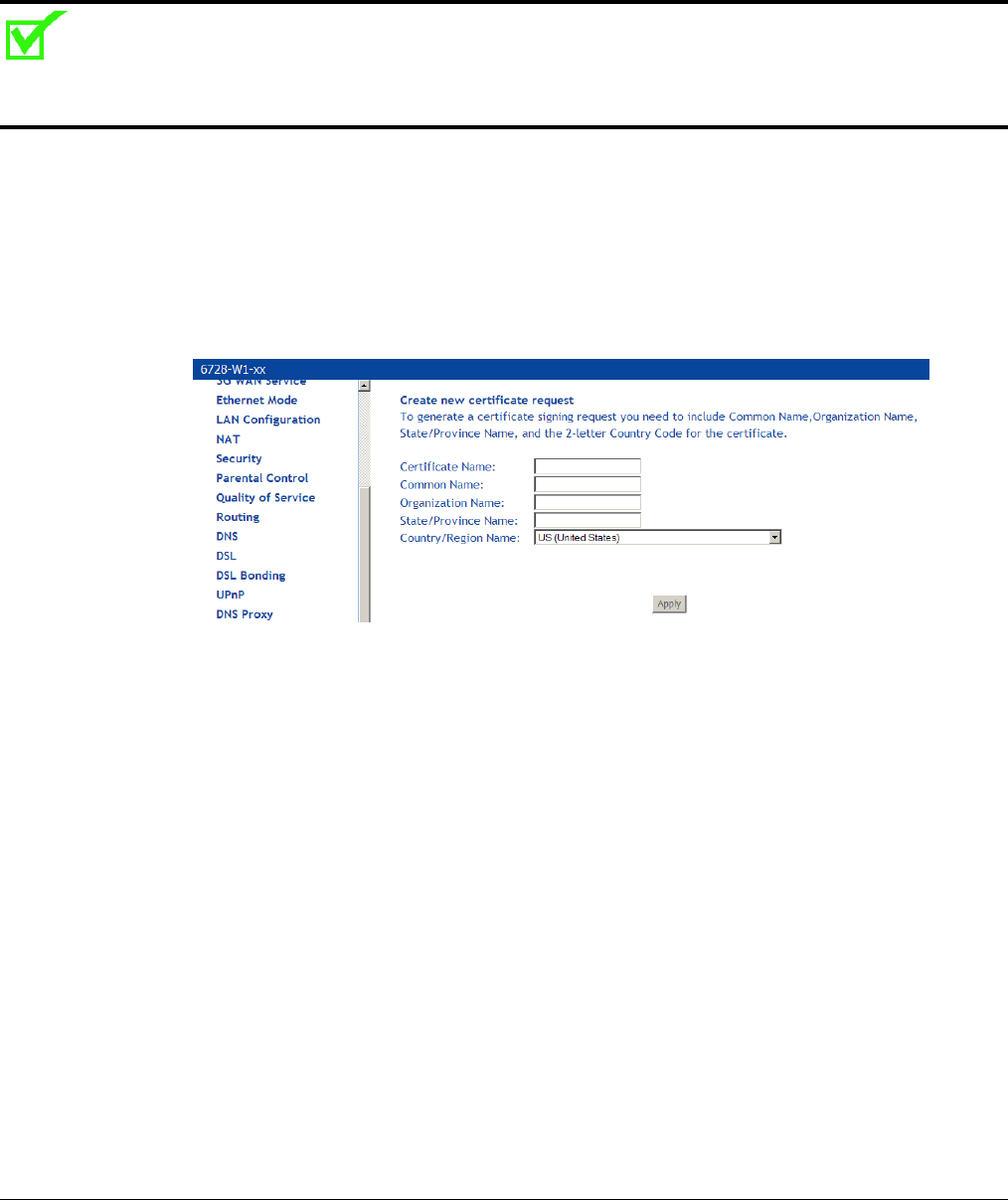
66xx/67xx Router Users Guide 125
Certificate
Use the Certificate screen to add, view, or remove a certificate for use by a peer to verify your
identity. A maximum of four certificates can be stored. You can add a certificate either by creating
a new one or importing an existing one from a location where one is stored.
Note: Certificates are used with TR-069. Firmware that does not support TR-069 will not support
certificates.
Local
A local certificate identifies your device over the network.
To apply for a certificate:
1. Click Create Certificate Request
The Create new certificate request screen allows you to create a new certificate request.
1. Follow the screens that appear to configure a new certificate.
2. Click Apply to submit the request.
If you have an existing certificate, click on Import Certificate to retrieve it. Paste the
certificate content and private key into the space provided. Click Apply to submit the
request to import the certificate.
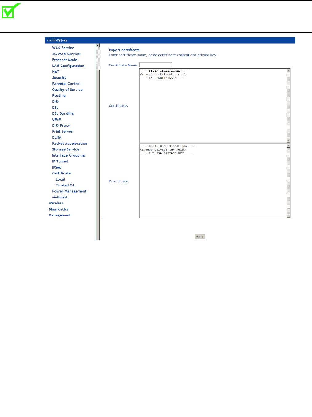
66xx/67xx Router Users Guide 126
Note: Importing a certificate requires you to reboot the router.
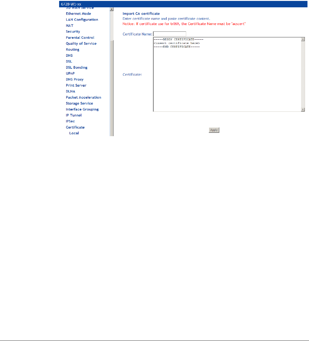
66xx/67xx Router Users Guide 127
Trusted CA
The trusted certificate authority (CA) allows you to verify the certificates of your peers.
The Trusted CA (Certificate Authority) Certificates screen also allows you to view certificates.
You can store up to 4 certificates.
To Import a certificate:
1. Click on Import Certificate
3. Enter the certificate name in the Certificate text box.
4. In the Certificate text window paste the content of the certificate.
5. Click Apply.
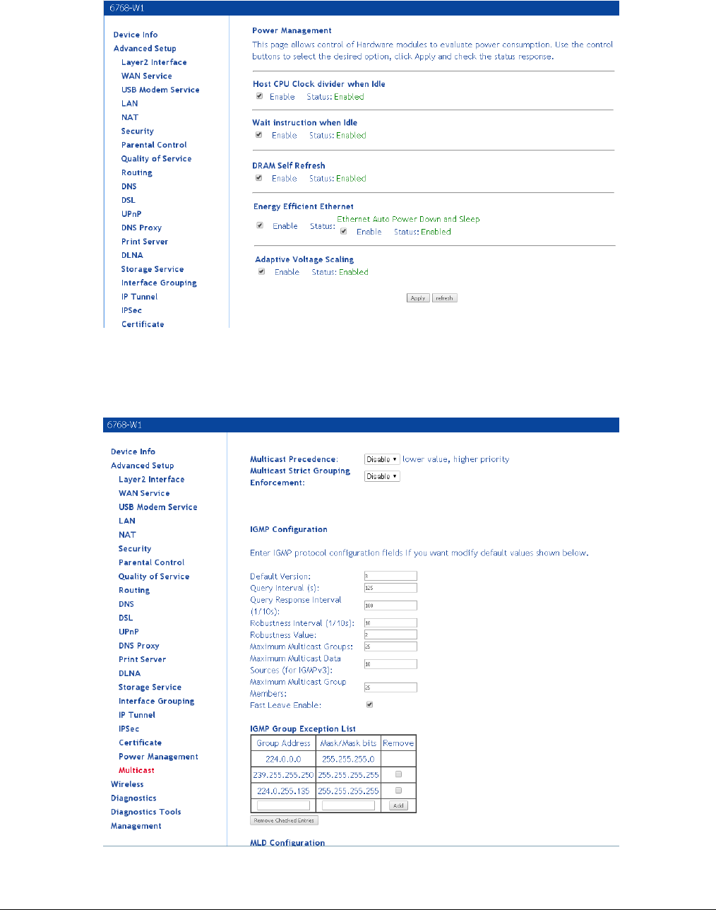
66xx/67xx Router Users Guide 128
Power Management
This page allows control of Hardware modules to evaluate power consumption.
Multicast
The Multicast screen allows you to configure IGMP settings or MLD settings for multicast.
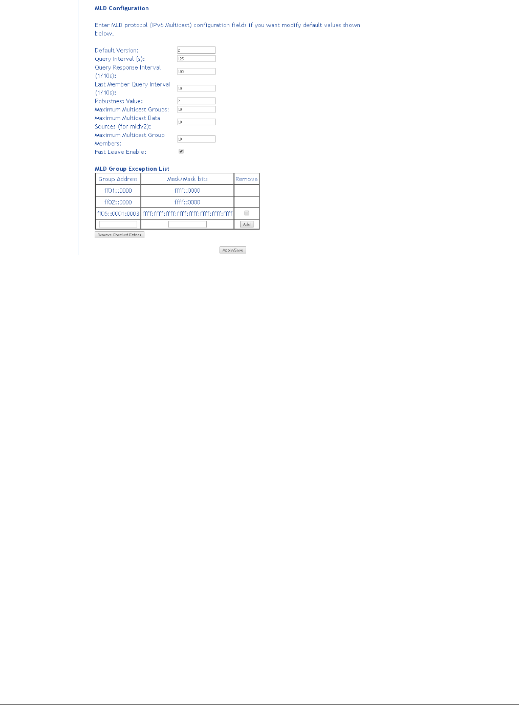
66xx/67xx Router Users Guide 129
Wireless
The router’s wireless feature can be configured to your needs. Sections covered under the
wireless section include
• Basic
• Security
• MAC filter
• Wireless bridge
• Advanced
• Station info.
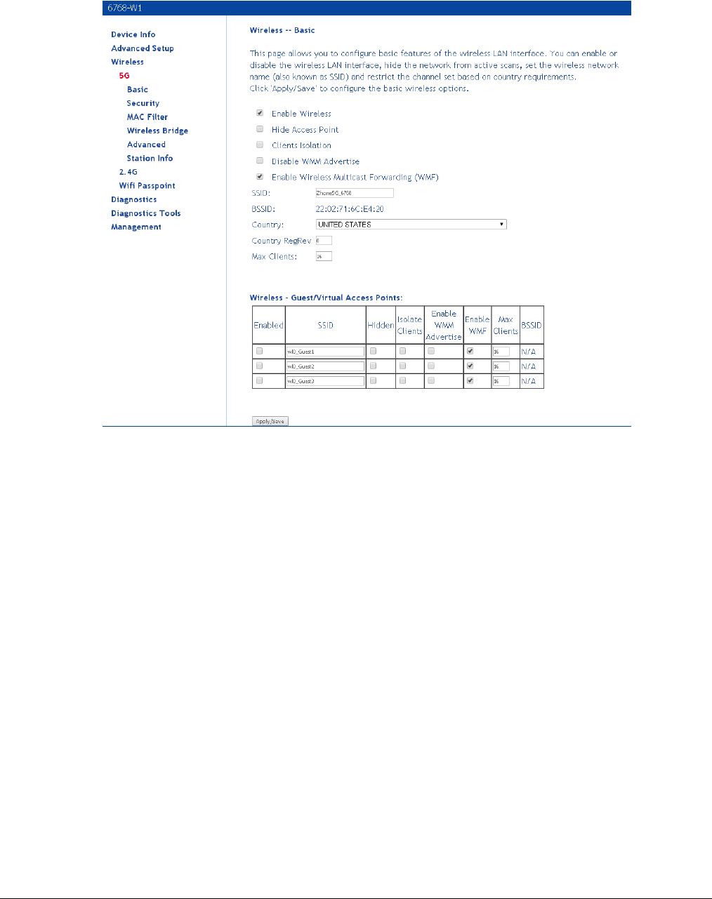
66xx/67xx Router Users Guide 130
5Gand 2.4G
For units with 5G and 2.4G in the same device, there is a menu for the 5G and 2.4 settings.
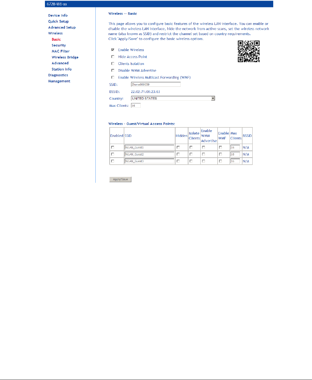
66xx/67xx Router Users Guide 131
Basic
The Wireless – Basic screen allows you to enable or disable the wireless function. You can also
hide the access point so others cannot see your ID on the network. If you enable wireless, be
sure to enter an SSID, your wireless network name and select the country that you are in.
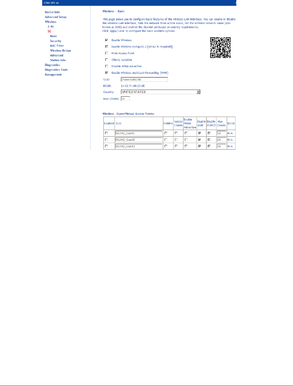
66xx/67xx Router Users Guide 132
The screens for the different variation of wireless, 2.4G and 5G, are very similar.
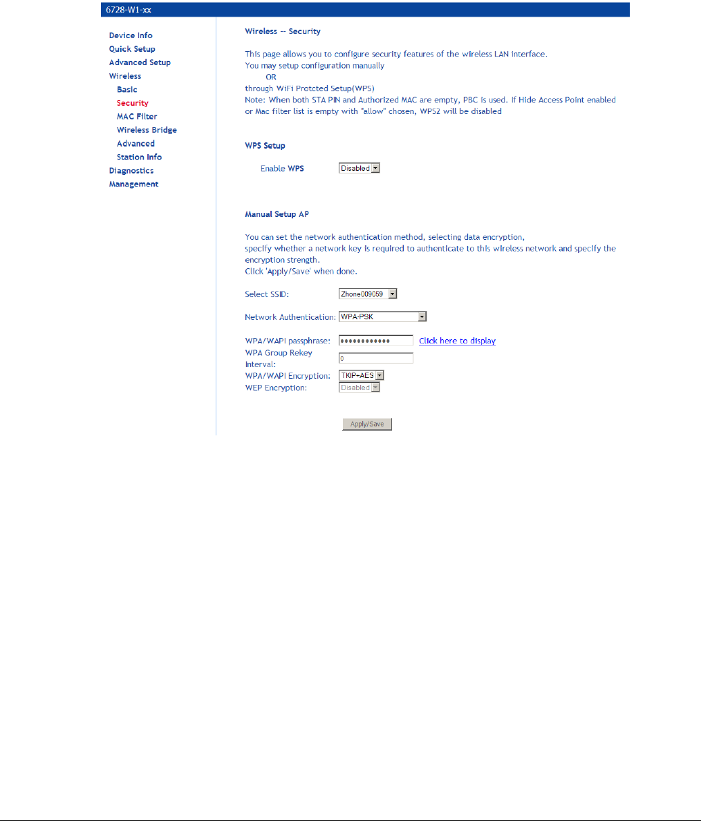
66xx/67xx Router Users Guide 133
Security
The Wireless – Security screen allows you to select the network authentication method and to
enable or disable WPS (WiFi Protected Setup).
The default setting is WiFi enable with WPS/PSK security. The pass phrase is printed on the label
at the bottom of the unit.
Note that depending on whether WPS is enabled and the network authentication method that is
selected, the screen will change accordingly so additional fields can be configured for the specific
authentication method.
WPS setup
• Enable WPS: WPS securely allows client access to the router. When you enable WPS,
clients must start the access process within two minutes. The router supports the PIN WPS
method only.
• Add Client: For WPA-PSK, WPA2 PSK or OPEN modes, enter a PIN, then click Add
Enrollee. The client must enter this PIN within two minutes to start the WPS procedure.
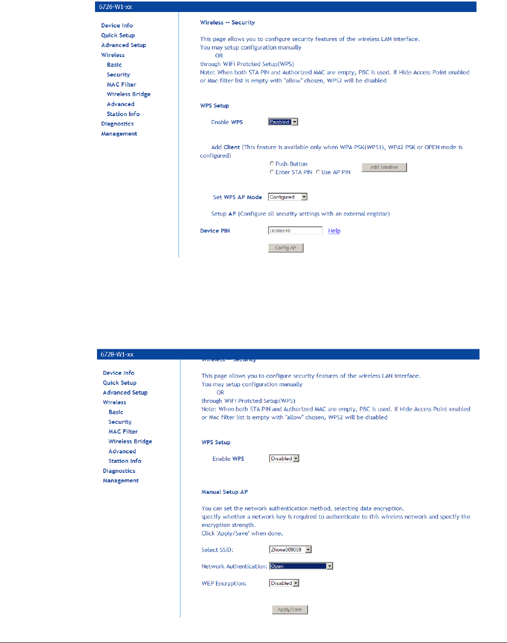
66xx/67xx Router Users Guide 134
• Set WPS AP Mode: If your provider is using an external registrar for security, select
Configured. The PIN for AP mode is specified by the registrar. Provide this PIN to the client.
Click Config AP to begin the registration process with the client.
Manual Setup AP
Network authentication methods include the following:
• Open: anyone can access the network. The default is a disabled WEP encryption setting.
Shared: WEP encryption is enabled and encryption key strength of 64-bit or 128-bit needs to be
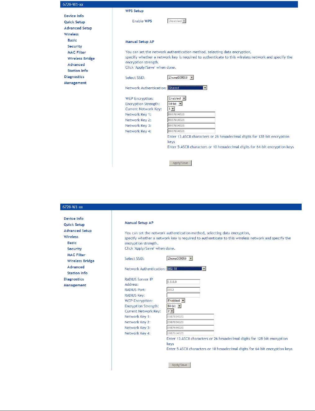
66xx/67xx Router Users Guide 135
selected. Click on Set Encryption Keys to manually set the network encryption keys. Up to 4
different keys can be set and you can come back to select which one to use at anytime.
802.1X: requires mutual authentication between a client station and the router by including a
RADIUS-based authentication server. Information about the RADIUS server such as its IP
address, port and key must be entered. WEP encryption is also enabled and the encryption
strength must also be selected.
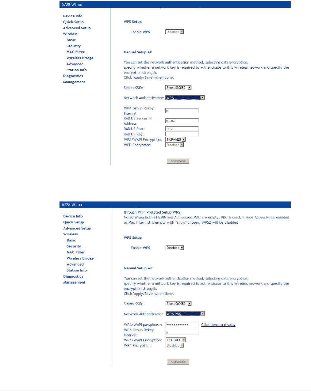
66xx/67xx Router Users Guide 136
WPA (Wi-Fi Protected Access): usually used for the larger Enterprise environment, it uses a
RADIUS server and TKIP (Temporal Key Integrity Protocol) encryption (instead of WEP
encryption which is disabled). TKIP uses 128-bit dynamic session keys (per user, per
session, and per packet keys).
WPA-PSK (Wi-Fi Protected Access – Pre-Shared Key): WPA for home and SOHO environments
also using the same strong TKIP encryption, per-packet key construction, and key
management that WPA provides in the enterprise environment. The main difference is that
the password is entered manually. A group re-key interval time is also required.
WPA2 (Wi-Fi Protected Access 2): second generation WPA which uses AES (Advanced
Encryption Standard) instead of TKIP as its encryption method. Network re-authorization
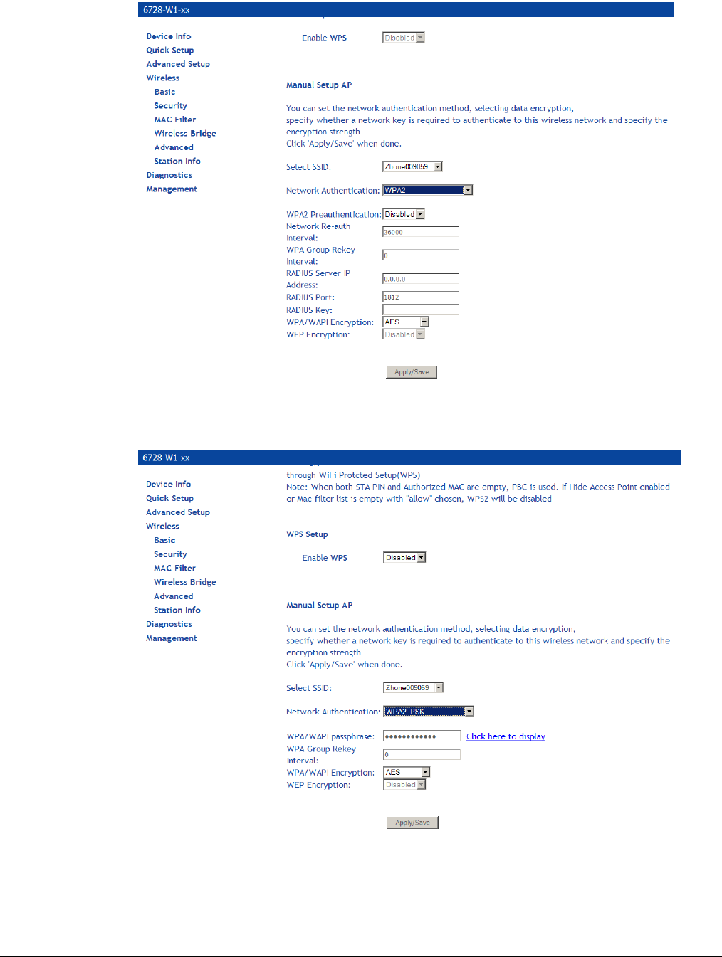
66xx/67xx Router Users Guide 137
interval is the time in which another key needs to be dynamically issued.
WPA2-PSK (Wi-Fi Protected Access 2 – Pre-Shared Key): suitable for home and SOHO
environments, it also uses AES encryption and requires you to enter a password and a re-key
interval time.
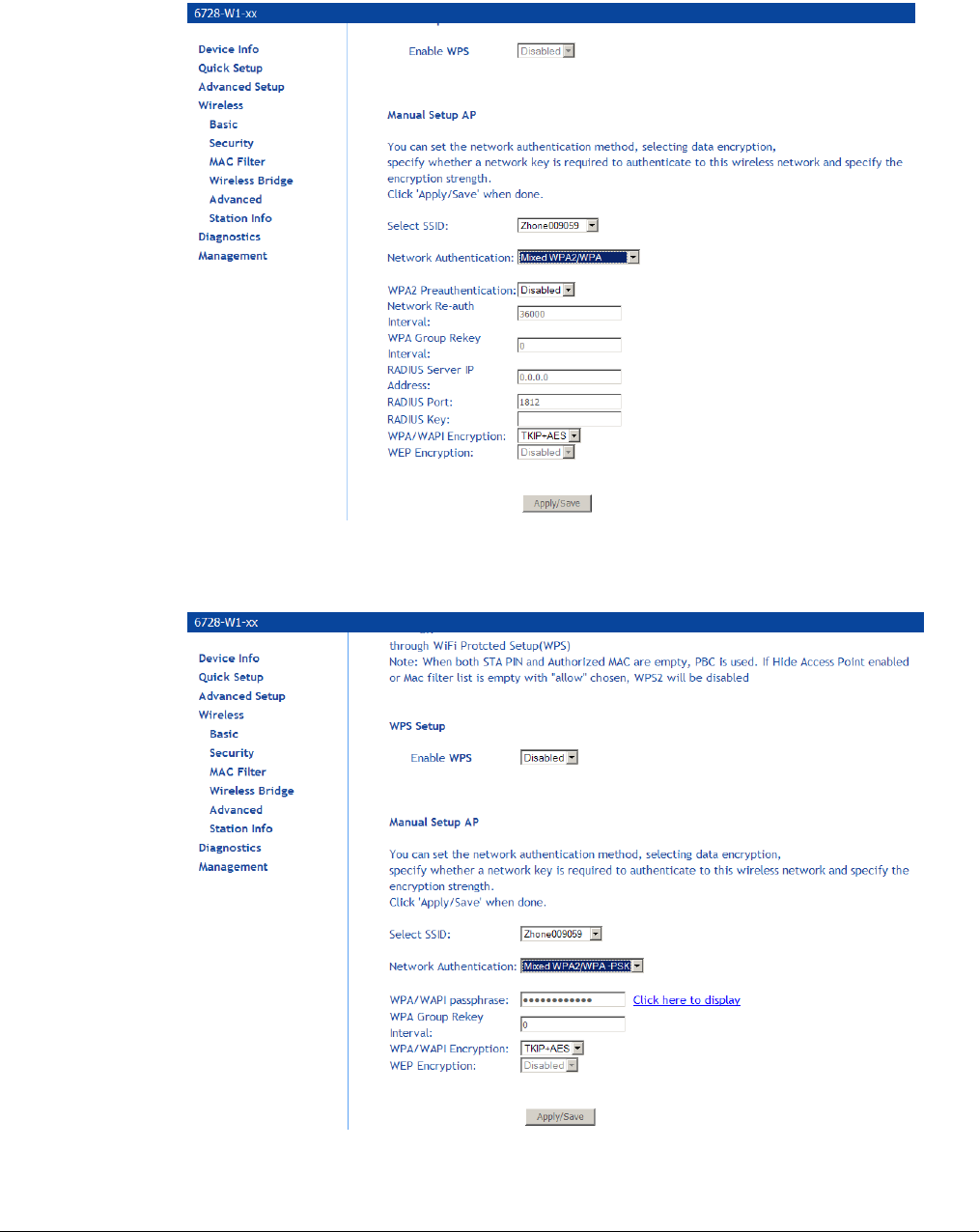
66xx/67xx Router Users Guide 138
Mixed WPA2 / WPA: useful during transitional times for upgrades in the enterprise environment,
this mixed authentication method allows “upgraded” and users not yet “upgraded” to access
the network via the router. RADIUS server information must be entered for WPA and a as
well as a group re-key interval time. Both TKIP and AES are used.
Mixed WPA2 / WPA-PSK: useful during transitional times for upgrades in the home or SOHO
environment, a pre-shared key must be entered along with the group re-key interval time.
Both TKIP and AES are also used.
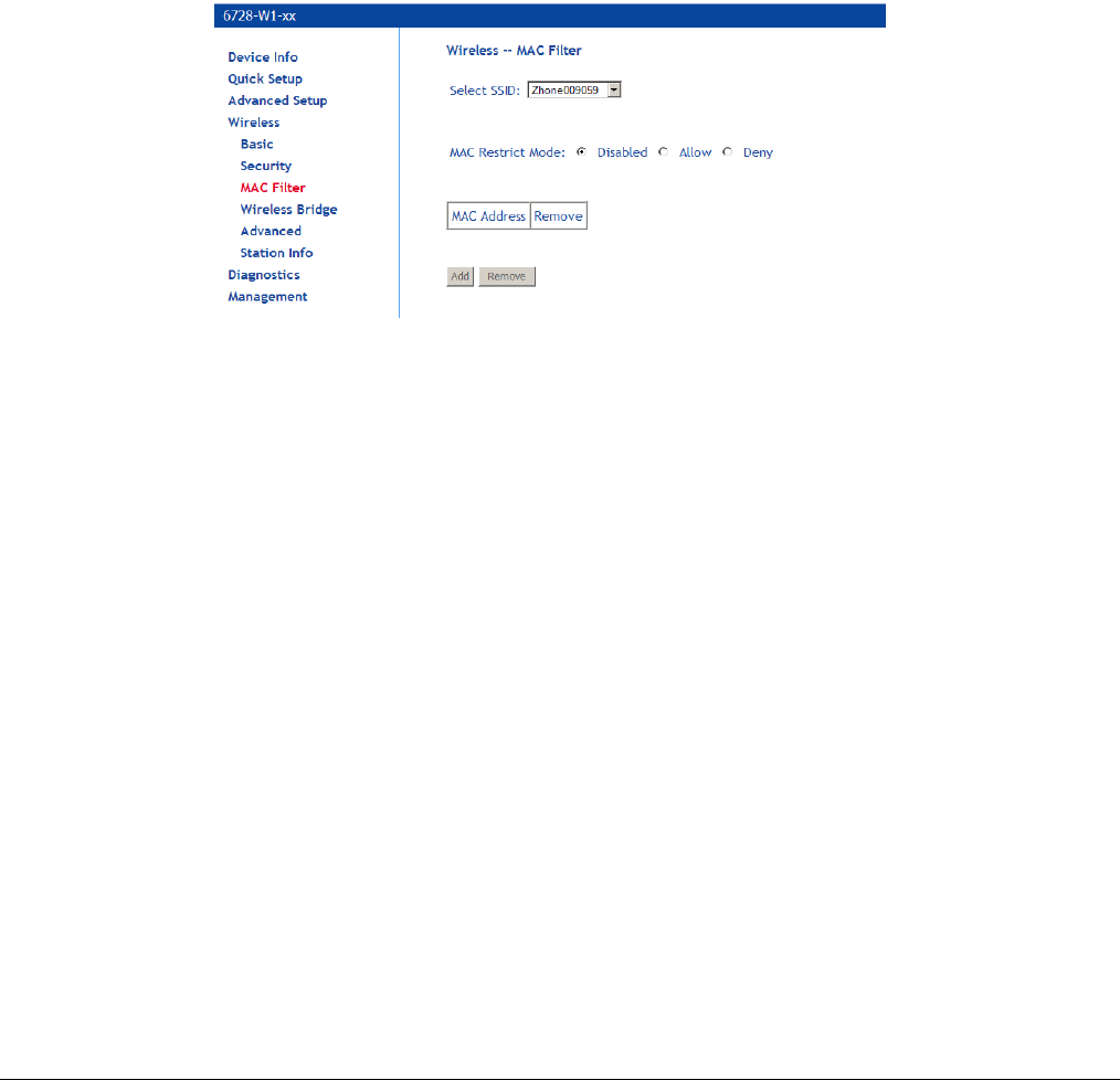
66xx/67xx Router Users Guide 139
MAC Filter
By default, MAC filter is disabled meaning any WiFi clients with the correct access will be allowed
to access the Access Point. The MAC filter screen allows you to control what WiFi clients are
allowed or deny to access the WiFi Access Point using the MAC address of the devices.
1. In the Wireless — MAC Filter page, select the SSID you want configure for WiFi client
access.
2. From one of the MAC Restrict Mode radio buttons, select Disabled, Allow or Deny, then
click on Add to add the MAC addresses you want to be able to access the WiFi network.
3. To block certain WiFi Clients from accessing the WiFi network, select Deny, then click Add
to add the MAC address of the WiFi client you want to block from Accessing the WiFi
network.
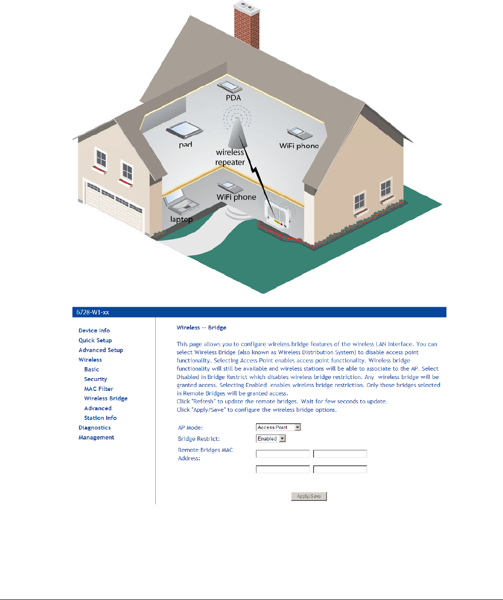
66xx/67xx Router Users Guide 140
Wireless Bridge
In the Wireless — Wireless Bridge screen, you can select the mode for the router, either access
point or wireless bridge. If you enable the bridge restrict option, then proceed to enter the MAC
addresses of the remote bridges.
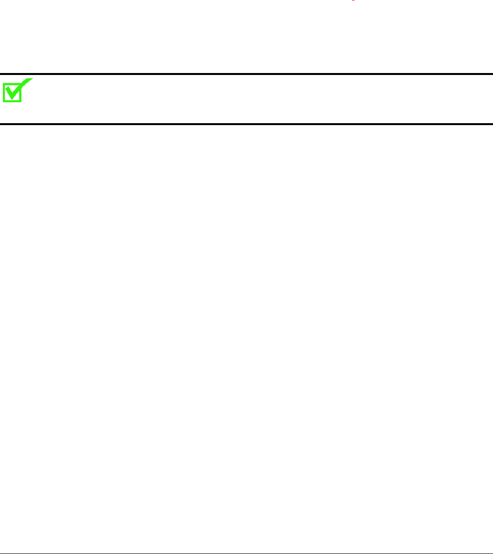
66xx/67xx Router Users Guide 141
To restrict a wireless bridge:
1. In the Wireless — Wireless Bridge screen select the access point mode from the AP Mode
dropdown.
AP Mode options are
Access Point
Wireless Bridge
2. From the Bridge Restrict dropdown select Enable, Disable or Refresh (Enabled Scan. If
you have chosen to enable access point, in the Remote Bridges MAC Address text
box(es) MAC address(es) for the bridge(s).
3. If you have chosen access point Enabled (Scan), select the MAC addresses to restrict.
Note: The wireless repeater may be required to be configured with the same SSID as the gateway.
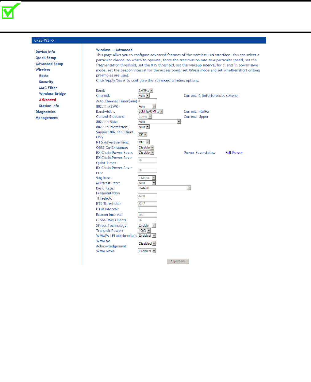
66xx/67xx Router Users Guide 142
Advanced
The Advanced page configures advanced features of the wireless LAN interface.
Note: Do not change the settings on this screen if you are not familiar with WiFi settings.
Band: a default setting at 2.4GHz – 802.11g
Channel: 802.11b , 802.11g and 802.11n use channels to limit interference from other devices. If
you are experiencing interference with another 2.4Ghz device such as a baby monitor,
security alarm, or cordless phone, then change the channel on your router.
Auto Channel Timer: (available if Channel is set to Auto) a timer that rescans and finds the best
available channel for use on your wireless network.
802.11n/EWC. Select Disabled for 54g. Select Auto to enable 802.11n.
Control Sideband: If you select 20MHz in Both Bands or 20MHz in 2.4G Band and 40MHz in 5G
Band, the service of control sideband does not work. When you select 40MHz in Both Bands
as the bandwidth, the following page appears. Then you can select Lower or Upper as the
value of sideband. As the control sideband, when you select Lower, the channel is 1~7.
When you select Upper, the channel is 5~11.
Bandwidth: Select the bandwidth.

66xx/67xx Router Users Guide 143
802.11n Rate: 802.11n data rate. Set to Auto to use the highest rate possible
802.11n Protection: Select Auto or Off.
Support 802.11n Client Only: Whether only 802.11n clients are able to connect.
RIFS Advertisement: Select Auto or Off.
OBSS Co-Existence: Select Enable or Disable.
RX Chain Power Save: Select Enable or Disable, then set the timing parameters. When enabled,
the WiFi receiver will shutdown when the period defined in RX Chain Power Save Quiet
Time occurs.
RX Chain Power Save Quiet Time: The Access Point will change to power save mode after the
number of seconds designated when RX Chain Power Save is set to Enable.
RX Chain Power Save PPS: The duration in seconds the Access Point will be in power save
mode.
54g Rate: The rate at which information will be transmitted and received on your wireless
network. Not settable when the router is set to 802.11n.
Multicast Rate: the rate at which a message is sent to a specified group of recipients.
Basic Rate: the set of data transfer rates that all the stations will be capable of using to receive
frames from a wireless medium.
Fragmentation Threshold: used to fragment packets which help improve performance in the
presence of radio frequency (RF) interference.
RTS Threshold (Request to Send Threshold): determines the packet size of a transmission
through the use of the router to help control traffic flow.
DTIM Interval: sets the Wake-up interval for clients in power-saving mode.
Beacon Interval: a packet of information that is sent from a connected device to all other devices
where it announces its availability and readiness. A beacon interval is a period of time (sent
with the beacon) before sending the beacon again. The beacon interval may be adjusted in
milliseconds (ms).
Global Max Clients: maximum number of clients allowed to connect to the router
Xpress Technology: a technology that utilizes standards based on frame bursting to achieve
higher throughput. With Xpress Technology enabled, aggregate throughput (the sum of the
individual throughput speeds of each client on the network) can improve by up to 25% in
802.11g only networks and up to 75% in mixed networks comprised of 802.11g and 802.11b
equipment.
Transmit Power: select from 20%, 40%, 60%, 80% and 100%. The default value is 100% but
can be changed.
WMM (Wi-Fi Multimedia): prioritizes traffic from different applications such as voice, audio and
video applications under different environments and conditions.
WMM No Acknowledgement: the acknowledgement policy used on the MAC level. Enabling no-
acknowledgement can result in efficient throughput but higher error rates in a noisy Radio
Frequency (RF) environment.
WMM APSD: APSD (Automatic Power Save Delivery). APSD manages radio usage for battery-
powered devices to allow battery life in certain conditions. APSD allows a longer beacon
interval until an application: VoIP for example: requiring a short packet exchange interval
starts. Only if the wireless client supports APSD does APSD affect radio usage and battery
life.

66xx/67xx Router Users Guide 144
Station Info
The Station Info page shows stations that have been authorized access to the router over WiFi.
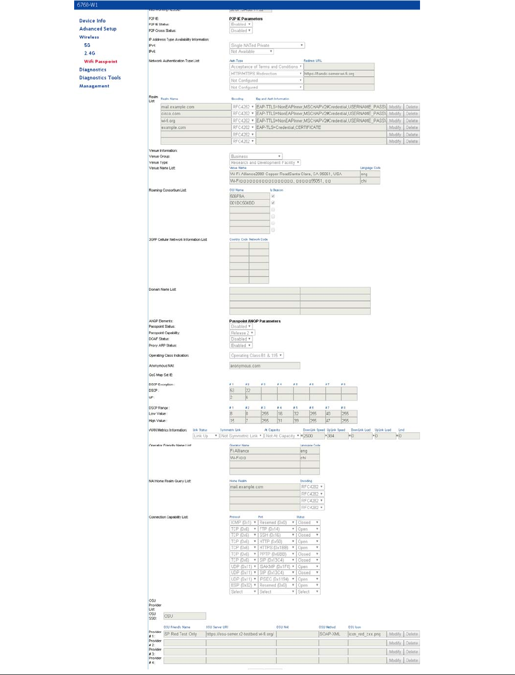
66xx/67xx Router Users Guide 145
WiFi Passpoint
66xx/67xx Router Users Guide 146
Voice
VoIP Status
The VoIP Status screen provides status of accounts and call times
The values for Registration Status
Up: The POTS line has been successfully registered
Down: The POTS line has not registered successfully
Disable: The account is not enabled
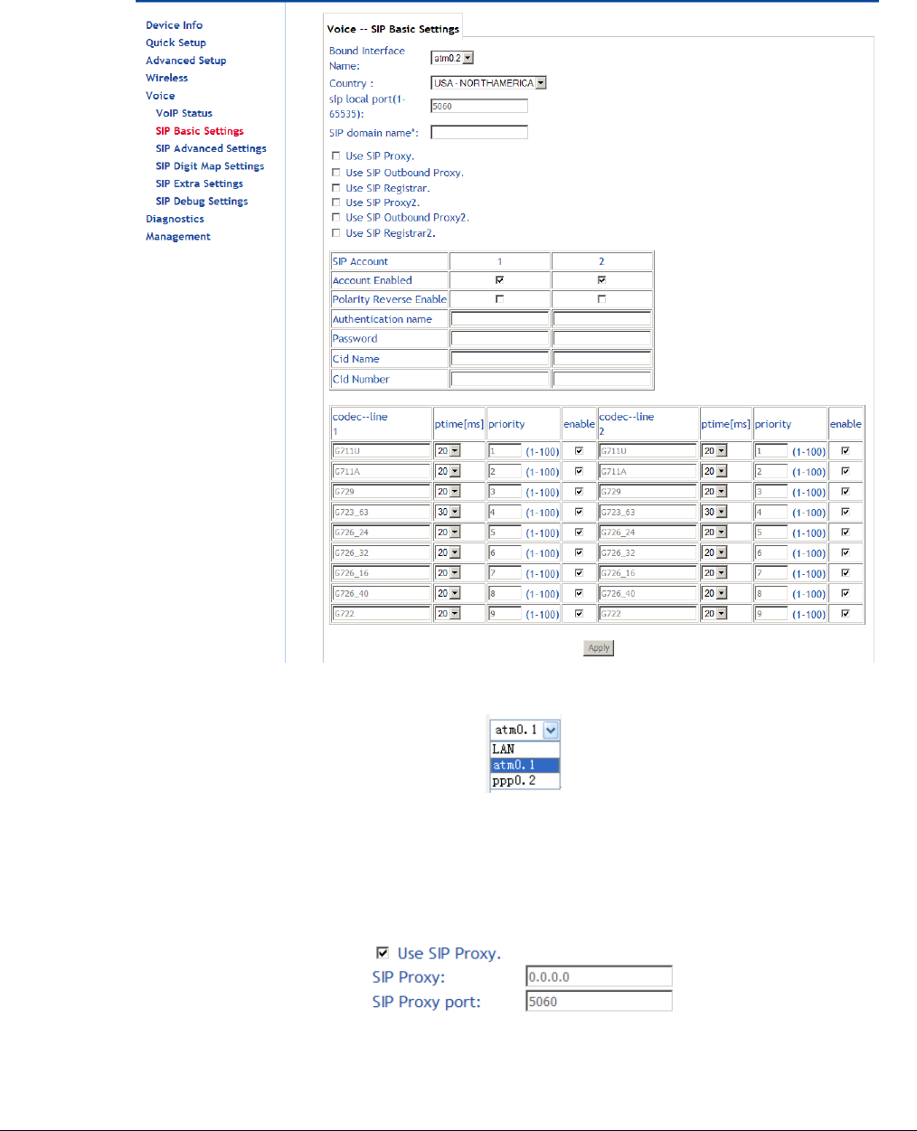
66xx/67xx Router Users Guide 147
SIP Basic Settings (Admin)
The SIP Basic Settings page configures many basic SIP settings.
Bound Interface Name: Select the interface to bind to the settings from the drop-down list.
SIP Local Port: Set the SIP local port of the gateway, the default value is 5060. SIP local port is
the SIP UA (user agent) port.
SIP domain name: Enter the SIP domain name.
Use SIP Proxy: If your DSL router uses a SIP proxy, select Use SIP Proxy. SIP proxy allows
other parties to call DSL router through it. When it is selected, the following fields appear.
SIP Proxy: The IP address of the proxy.
SIP Proxy port: The port which this proxy is listening on. By default, the port value is 5060.
Use SIP Outbound Proxy: Some network service providers require the use of an outbound
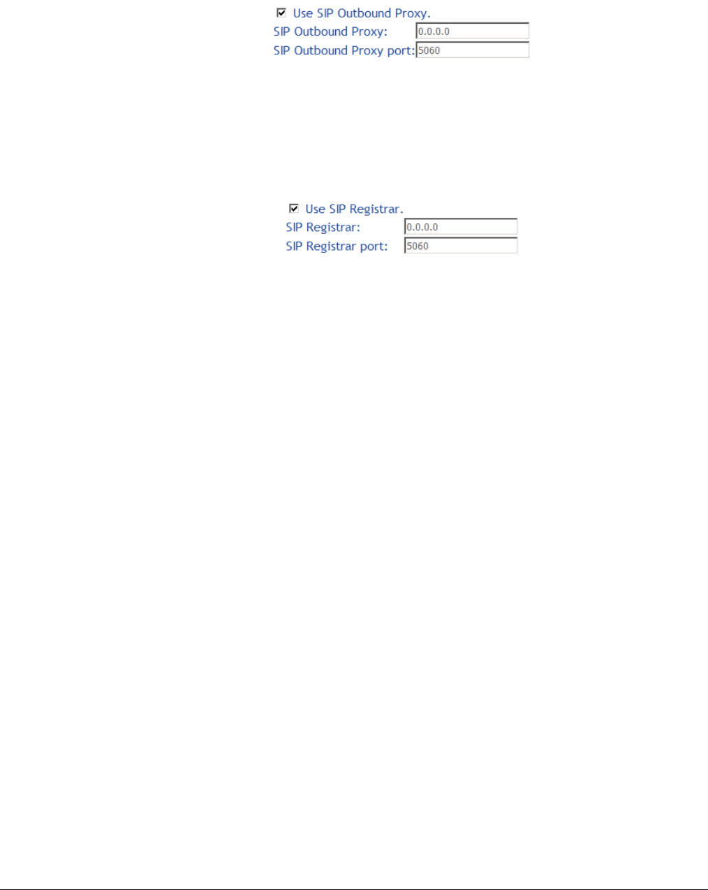
66xx/67xx Router Users Guide 148
proxy. This is an additional proxy through which all outgoing calls are directed. In some
cases, the outbound proxy is placed alongside the firewall and is the only way to let SIP
traffic pass from the internal network to the Internet. When SIP Outbound Proxy is selected,
the following fields appear.
SIP Outbound Proxy: The IP address of the outbound proxy.
SIP Outbound Proxy port: The port that the outbound proxy is listening on. By default, the port
value is 5060.
Use SIP Registrar: Select the checkbox of Use SIP Registrar to register with the proxy. You can
register your user ID on the SIP registrar. SIP registrar works with SIP proxy, allowing other
parties to call DSL router through it. When it is selected, the following fields appear.
SIP Registrar: The IP address of the SIP registrar.
SIP Registrar port: The port that SIP registrar is listening on. By default, the port value is 5060.
Account Enabled: If Account Enabled is not selected, the corresponding account is disabled.
You can not use the account to initiate or accept any call.
Polarity Reverse Enable: Enable or disable this function.
Authentication name: Set the user name of authentication.
Password: Set the password of authentication.
Cid Name: User name. It is the Display Name.
Cid Number: Set the caller number. It must be a number of 0~9.
ptime: You can use the ptime parameter to set the packetization time (PT). The PT is the length
of the digital voice segment that each packet holds. The default setting is to create 20
millisecond packets. Selecting 10 milliseconds for the parameter may improve the voice
quality. Because of the packet loss, less information is lost, but because there are more
packets and a smaller payload to overhead ratio per packet, selecting 10 milliseconds puts a
heavier load on the network traffic.
Priority: The priority of codec is defined in a range from 1-100. Codecs define the method of
relaying voice data. Different codecs have different characteristics, such as data compression
and voice quality. For Example, G723 is a codec that uses compression, therefore, it is a
good option when bandwidth is limited, however the voice quality for G723 is not good as
other codecs, such as the G711. If no codec is specified, the DSL router chooses the codec
automatically.
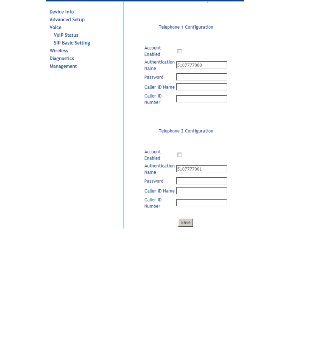
66xx/67xx Router Users Guide 149
SIP Basic Settings (User)
The user may configure some basic SIP settings as well. The subscriber can enable the VoIP
account using information from ISP
The ISP would only need to populate the SIP server information and leave the user account
empty (and SIP account disabled). When Subscriber VoIP services are given, the user can then
add the information provided by ISP
See above “SIP Basic Settings (Admin)” for descriptions of the items.
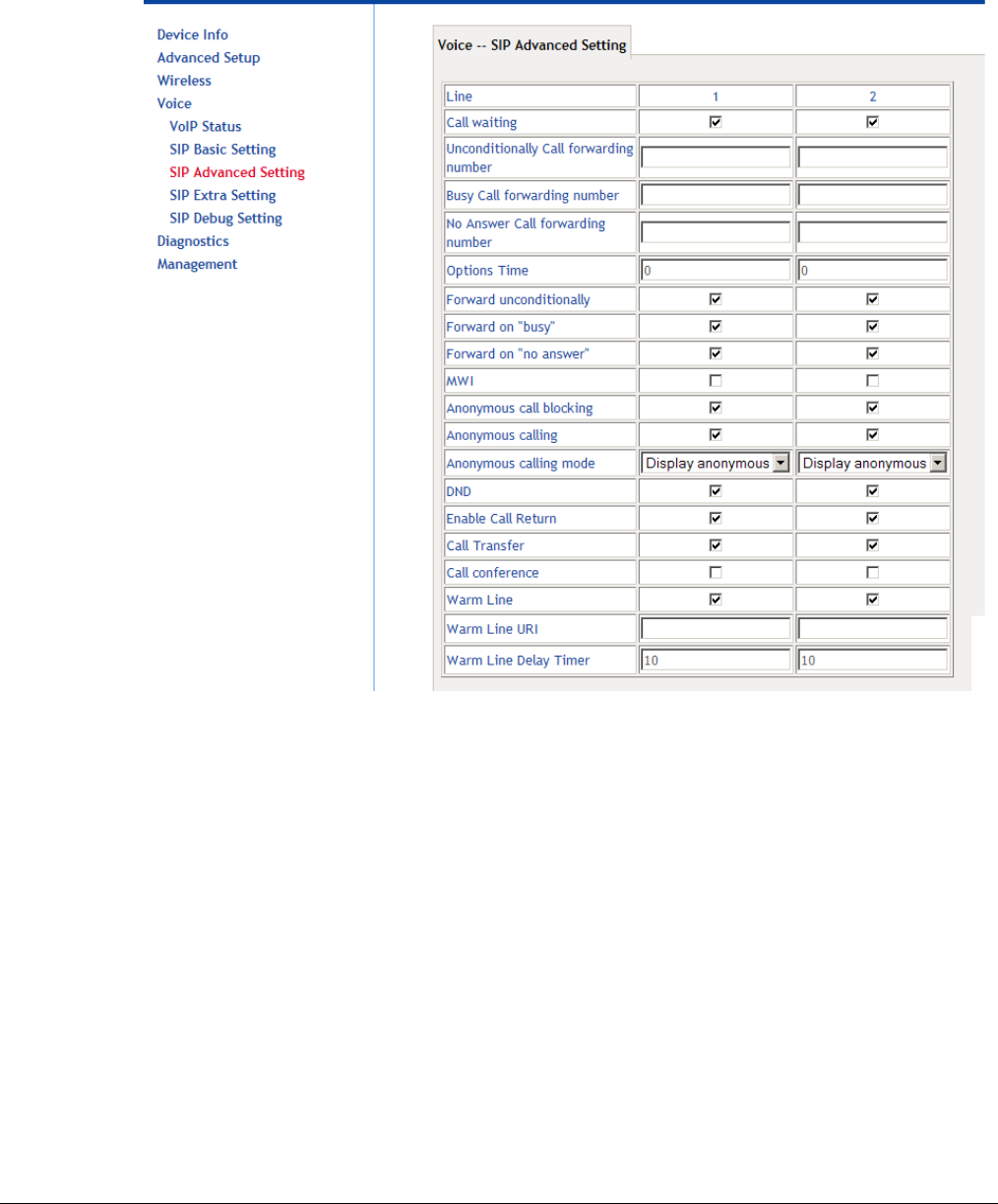
66xx/67xx Router Users Guide 150
SIP Advanced Settings
The advanced settings cover many important features such as call waiting, call forwarding,
showing that a voicemail is waiting, blocking calls from anonymous sources, or making
anonymous calls.
Line: The line to configure.
Call waiting: If call waiting is enabled on a line, you can hear the call waiting tone during a call,
press FLASH on the phone to answer the second call. The first call is automatically placed
on hold. To switch between calls, press FLASH again.
Note: The call forward feature settings (Busy or All) take priority over the call waiting feature.
Note: The call waiting feature is ignored on new incoming calls if there is already a call on hold or
in conference.
Unconditionally Call forwarding number: Enter the number to which all incoming calls will be
forwarded.
Busy Call forwarding number: Enter the number to which incoming calls will be forwarded when
the line is busy.
No Answer Call forwarding number: Enter the number to which incoming calls will be
forwarded when the call is not answered.
Options Time: Set the time interval for sending the Options message.
Forward unconditionally: Select to enable forwarding all incoming calls.
Forward on "busy": Select to enable forwarding incoming calls when the line is busy.
Forward on "no answer": Select to enable forwarding when the call is not answered.
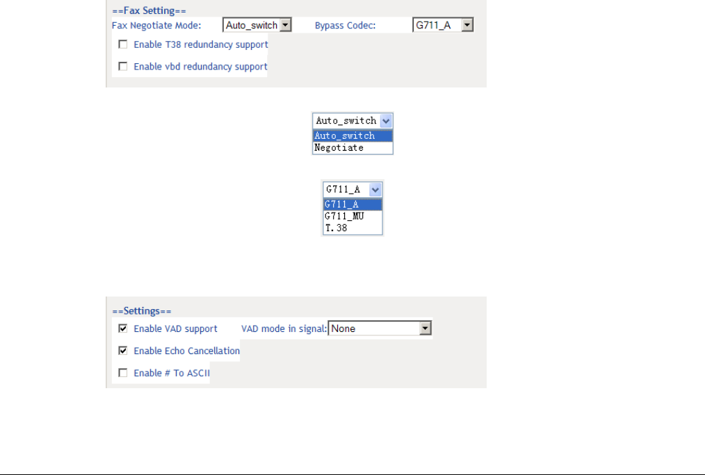
66xx/67xx Router Users Guide 151
MWI: The message waiting indicator (MWI) provides a MWI tone to the user’s receiver when
there is a waiting voicemail.
Anonymous call blocking: Select Anonymous call blocking to block calls which do not give a
user’s number.
You can also dial *77 to enable this feature. Dial *87 to disable this feature.
NOTE: This feature is a local supplementary feature and may be in conflict with the
supplementary feature offered by the softswitch.
Anonymous calling: Select Anonymous calling to use “Anonymous” rather than the phone
number when making calls.
You can also dial *68 to enable this feature. Dial *82 to disable this feature.
DND: Select to reject all incoming calls.
You can also Dial *78 to enable the feature.
Enable Call Return: Select to enable call return.
When the local supplementary feature is enabled, dial *69 for call return, the ability to dial the
last number that called.
Call Transfer: When set a call transfer is initiated by a flash-hook followed by a valid number in
the dial plan.
Call Conference:
Warm Line: Warm line provides dial tone from the off hook event and allows you to dial a number
for an amount of time, then when the time has elapsed (Warm Line Delay Timer) the number
set in Warm Line URI will be called.
Warm Line URI: The number to call when the Warm Line Delay Timer amount of time has been
reached.
Warm Line Delay Timer: An amount of time to wait before calling the Warm Line URI.
Fax Negotiate Mode: You can select it from the drop-down list.
Bypass Codec: Select the bypass codec from the drop-down list.
Enable T38 redundancy support: Select to enable redundancy support for T38 fax calls..
Enable vbd redundancy support: Select to enable voiceband data redundancy support.
Voiceband data uses a voiceband codec for the transport of data.
Enable VAD Support: Enable Voice Activation Detection for the line. Select None to have the
line ignore silence suppression for the SDP session. Select Silencsupp to use silence
suppression. Select Annexa|Annexb|VAD to use the Annex A or Annex B settings from the
RTP defined by the selected CODEC.
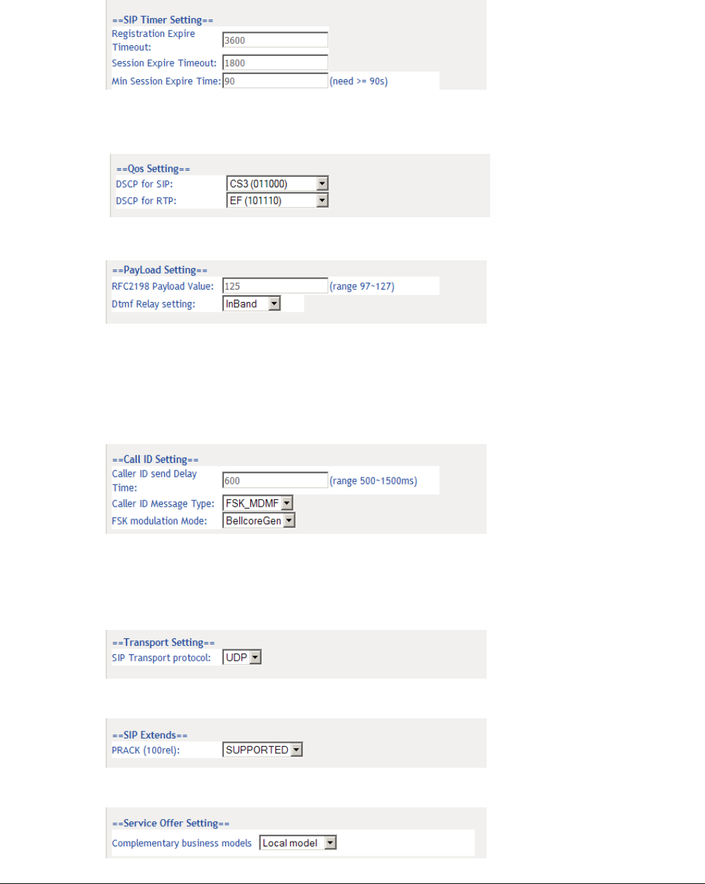
66xx/67xx Router Users Guide 152
Enable Echo Cancellation: Enables echo cancellation.
Enable # to ASCIIL: When enabled “#” will be converted to “%23” in the SIP messages. When
disabled “#” will be sent.
Registration Expire Timeout*: Enter the registration expire timeout (in seconds).
Session Expire Time: The interval of dialog refreshing time (in seconds).
Min Session Expire Time: The minimum interval of dialog refreshing time (in seconds).
DSCP for SIP: Set the DSCP for SIP.
DSCP for RTP: Set the DSCP for RTP.
RFC2198 Payload Value (range 96~127): Enter the RFC2198 payload value. The valid range is
96 ~ 127.
Dtmf Relay Setting: Set DTMF transmit method, which can be following values:
SIP Info: Use SIP INFO message to transmit DTMF digits.
RFC2833: Use RTP packet to encapsulate DTMF events, as specified in RFC 2833.
InBand: DTMF events are mixed with user voice in RTP packet.
Caller ID Send Delay Time: The amount of time from call initiation to send the Caller ID.
Caller ID Message Type: Set the Caller ID message type to send — FSK, FSK_MDMF, or DTMF
FSK Modulation Mode: Depending on the options set in Caller ID Message Type, this drop down
sets the FSK (Frequency-Shift-Keying) modulation — Bell Core, V.23 (general), V.23 UK
version (sends out the FSK before the first ring).
SIP Transport Protocol: Select the transport protocol to use for SIP signaling. Note that the SIP
proxy and registrar need to support the protocol you select.
PRACK (100rel): SIP Provisional Response Acknowledgement (RFC 3262, Reliability of
Provisional Responses in the Session Initiation Protocol (SIP)).
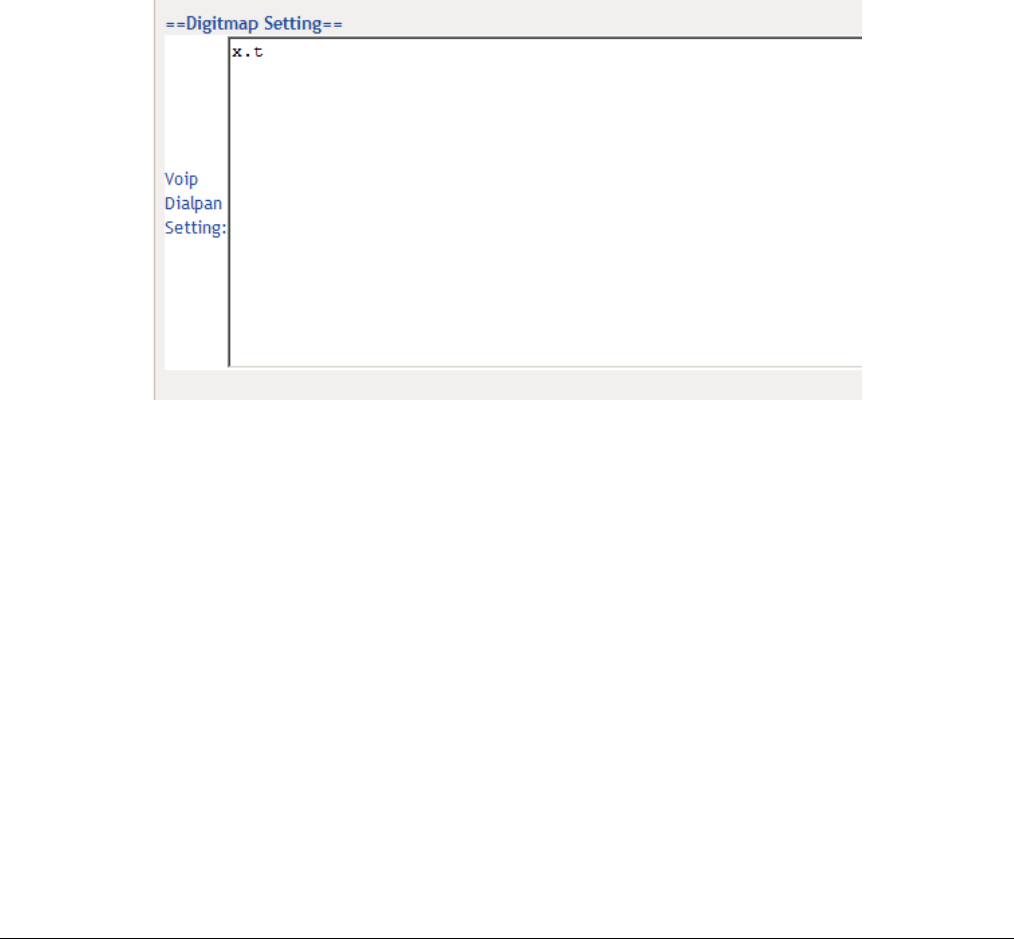
66xx/67xx Router Users Guide 153
Complimentary Business Models
Local Model: The service is supported by the gateway rather than by a SoftSwitch.
Server Model: (for softx3000) Flash hook is sent via INFO.
IMS Model: (for Hauwei, ZTE IMS) support FLASHHOOK and INFO modes.
Undefined
Enable Local Supplementary Service: Select to enable the supplementary service settings by
the telephone set. If you deselect the checkbox, the supplementary service can not be set by
the telephone set. Zhone recommends not selecting Local Supplementary Service. Not
selecting Local Supplementary Service allows the softswitch to act upon the * codes based
on the supplementary services offered by the softswitch.
SIP Digit Map Settings
A dialing plan for POTS-to-SIP outgoing calls consists of a series of acceptable dial strings. If an
acceptable dialplan is not entered which matches one of the acceptable dial strings entered in the
Digit Map Setting window, the call will not proceed.
The following rules are used to configure the dialplan:
Each dial string is represented as digits, wildcards, and regular-expression-like patterns.
Digits “0” to “9” are allowed as well as “*” and “#”. The character “x” indicates a wildcard for 0
or more digits between 0-9.
The character “T” or “t” designates an override for the interdigit timeout.
Brackets “[]” define digit range. [135] means digits 1, 3, or 5. [1-4] means digits 1, 2, 3, or 4.
The use of “.” represents any digit and a ‘|’ character indicates an inclusive OR, so “*.xT | x.T “
indicates star plus any number of digits followed by the inter-digit timeout.
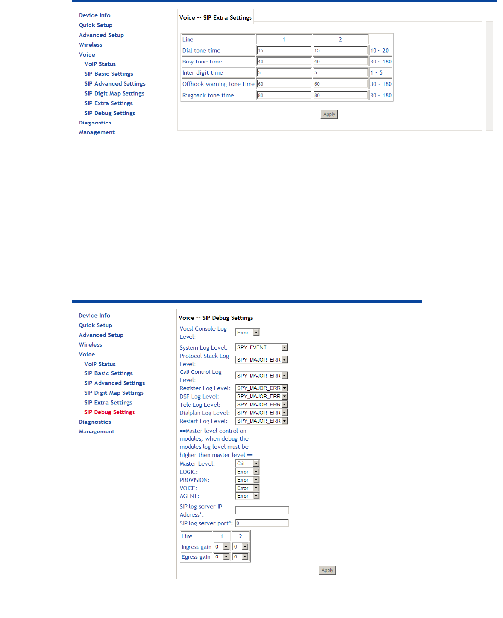
66xx/67xx Router Users Guide 154
SIP Extra Settings
The SIP Extra Settings page sets the dial tone time, busy tone time, inter digit time, offhook
warning time and ringback tone time. All times are in seconds.
Dial tone time: Dial tone duration.
Busy tone time: Busy tone duration.
Inter digit time: The valid range is 1 ~ 5.
Offhook warning tone time: Offhook warning tone duration.
Ringback tone time: Ringback tone duration
SIP Debug Settings
The SIP Debug Settings screen sets log levels, the SIP log server IP address and port, and
adjust gain on the line.
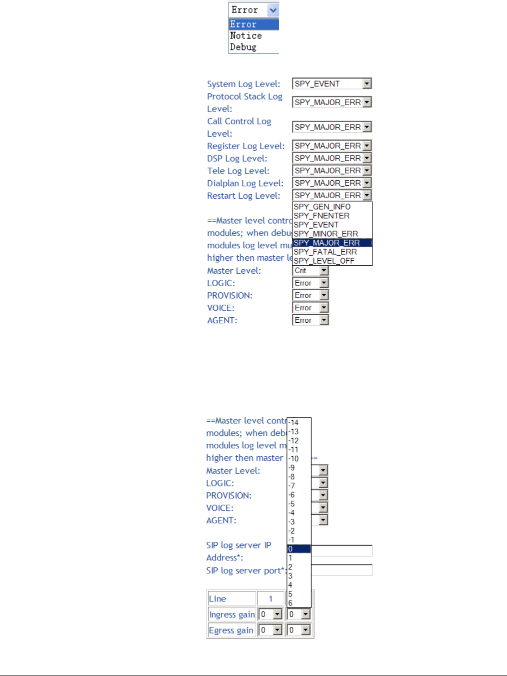
66xx/67xx Router Users Guide 155
Vodsl Console Log Level: Select it from the drop-down list.
Log Settings: The log levels can be set for many types of events as shown in the below graphic.
SIP Log Server Settings: Set SIP log server IP address and port, then the log message of the
VoIP is sent to the device which IP address you set to. If you want use this function, both of
the IP address and port must be set correctly.
Gain Settings: Gain is a measure of the ability of a circuit (often an amplifier) to increase the
power or amplitude of a signal. You can increase or decrease ingress gain and egress gain.
The range of the value is from -14 to 6
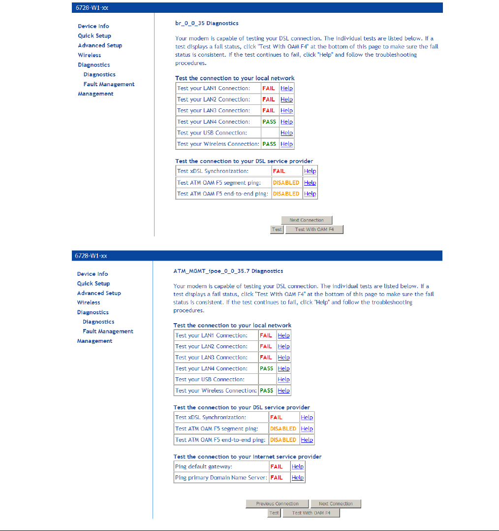
66xx/67xx Router Users Guide 156
Diagnostics
The diagnostics screen allows you to run diagnostic tests to check your DSL connection. The
outcome will show test results of three connections:
Connection to your local network
Connection to your DSL service provider
Connection to your Internet service provider
The Test and Test with OAM F4 buttons allow you to retest if necessary.
Click the Next Connection button to test your router’s next connection.
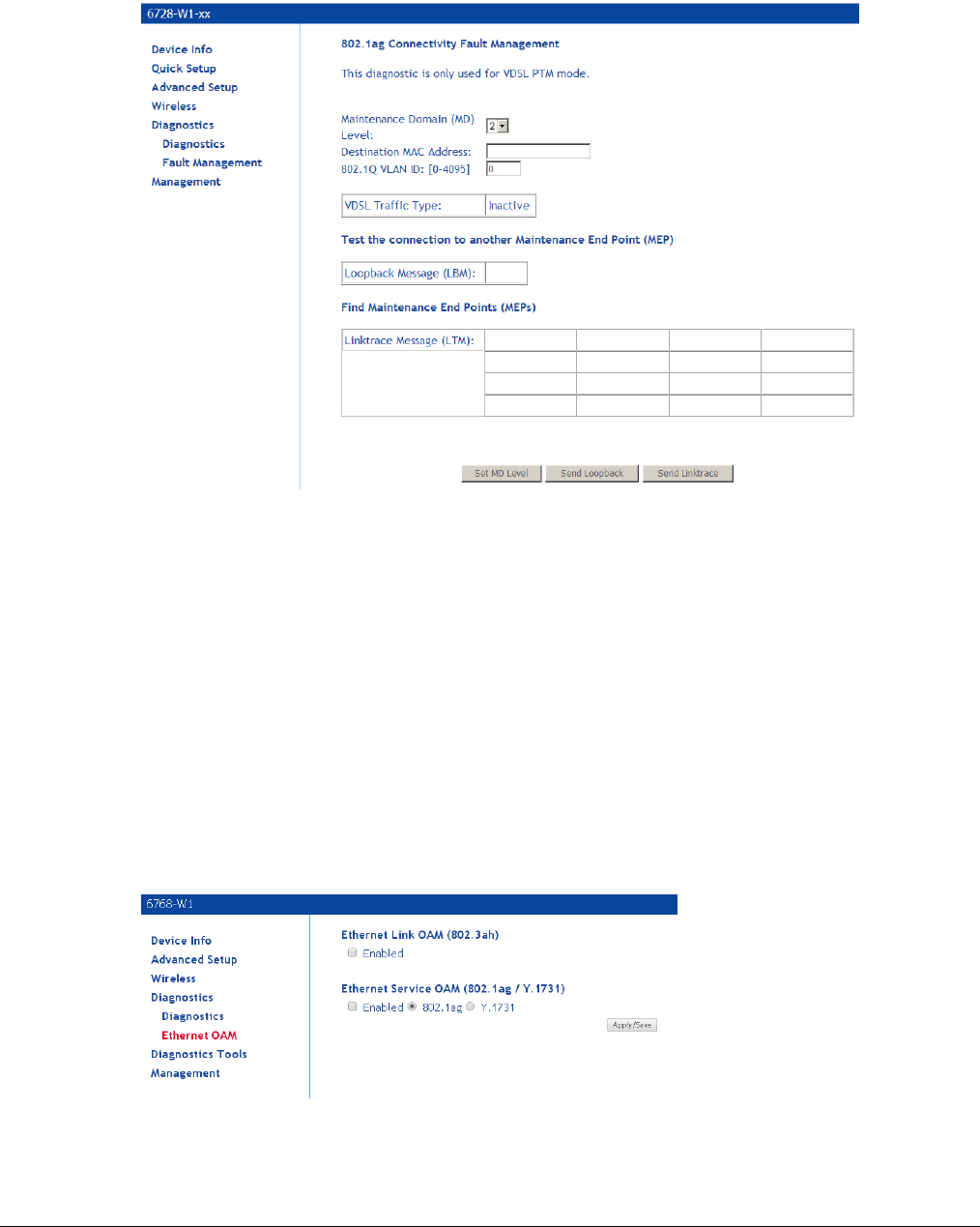
66xx/67xx Router Users Guide 157
Fault Management
The Fault Management screen displays information to help troubleshoot faults with the router.
• Maintenance Domain: Determine the device that receives and passes through the CFM
(Connectivity Fault Management) frame.
• Destination MAC Address: Destination MAC address (where the fault detection packets will
be sent).
• 802.1Q VLAN ID: Enter the 802.1Q VLAN
Click Set MD Level to apply the MD level. Then click Send Loopback to send the loopback
frame or Send Linktrace to find the maintenance endpoints.
Ethernet OAM
The Ethernet OAM page enables the device to respond to OAM 802.3ah diagnostics and OAM
802.1ag/Y1731 diagnostic
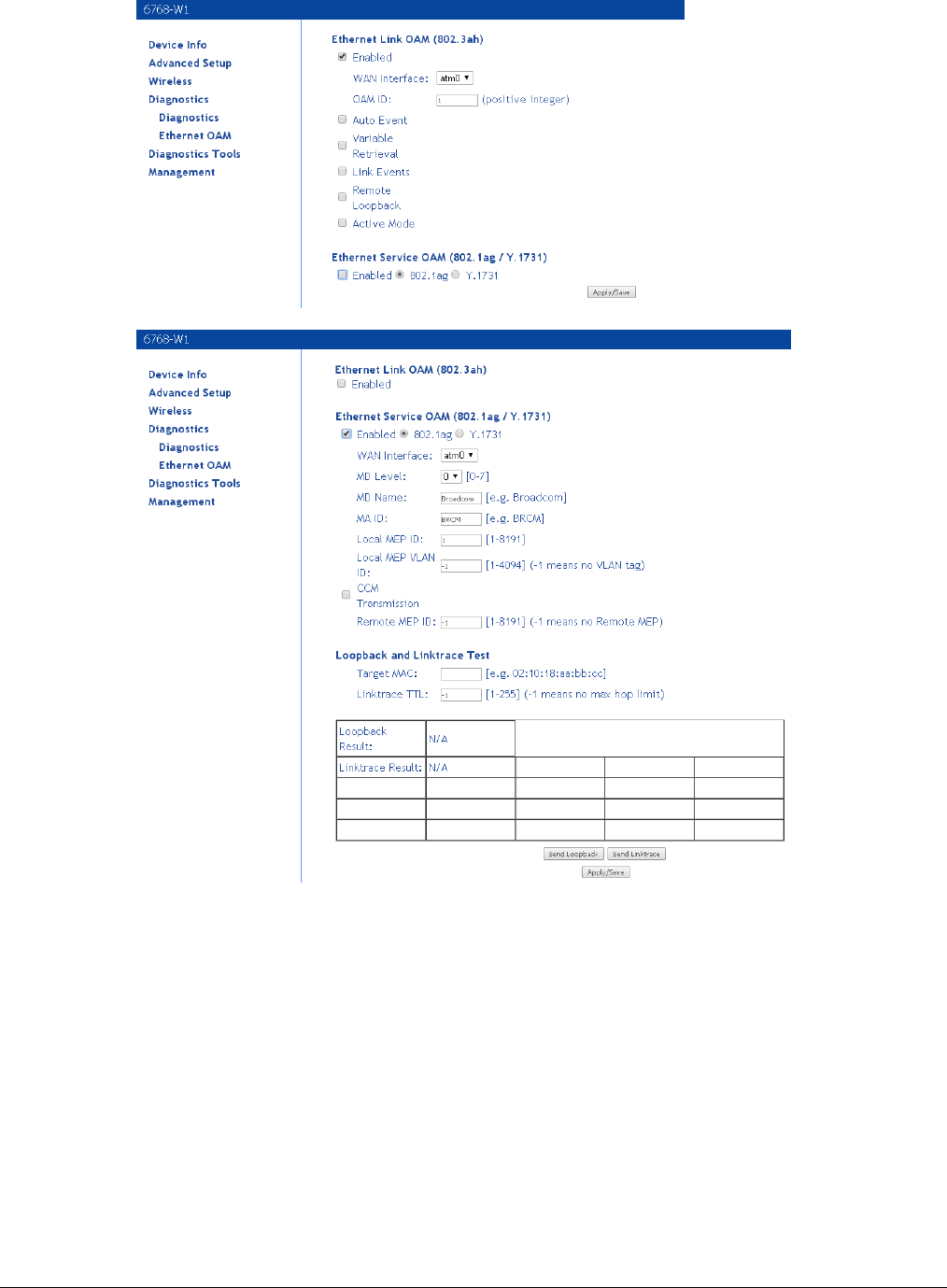
66xx/67xx Router Users Guide 158
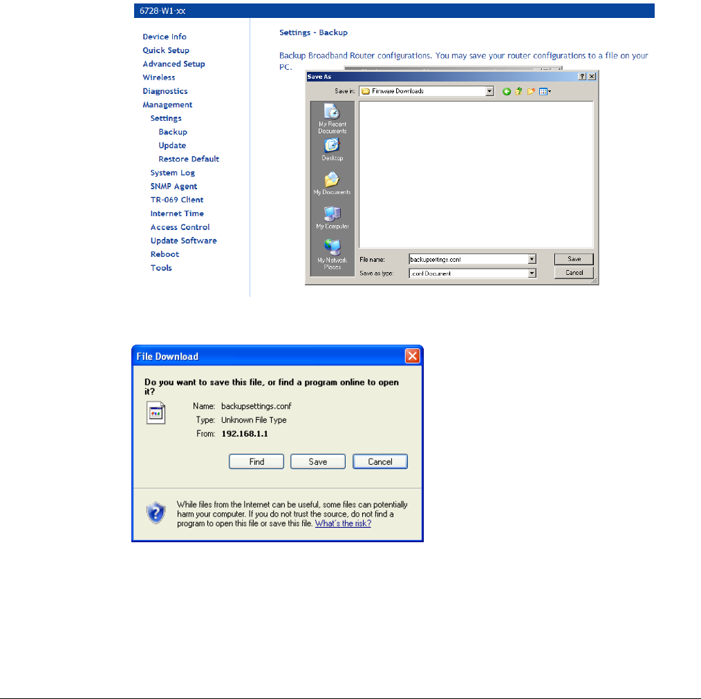
66xx/67xx Router Users Guide 159
Management
The Management section gives you access to certain setups for the purpose of maintaining the
system, including backing up the configurations, viewing system log, maintaining access control,
updating software, etc.
Settings
Backup Settings
To save a copy of the configurations that you have made on your router:
1. From the Settings – Backup page click Backup Settings.
The pop-up screen similar to the one below will appear with a prompt to open or save the file
to your computer.
2. Click Save.
Update Settings
To load a previously saved configuration file onto your router:
1. From the Settings – Update Settings page, click Browse to find the file on your computer.
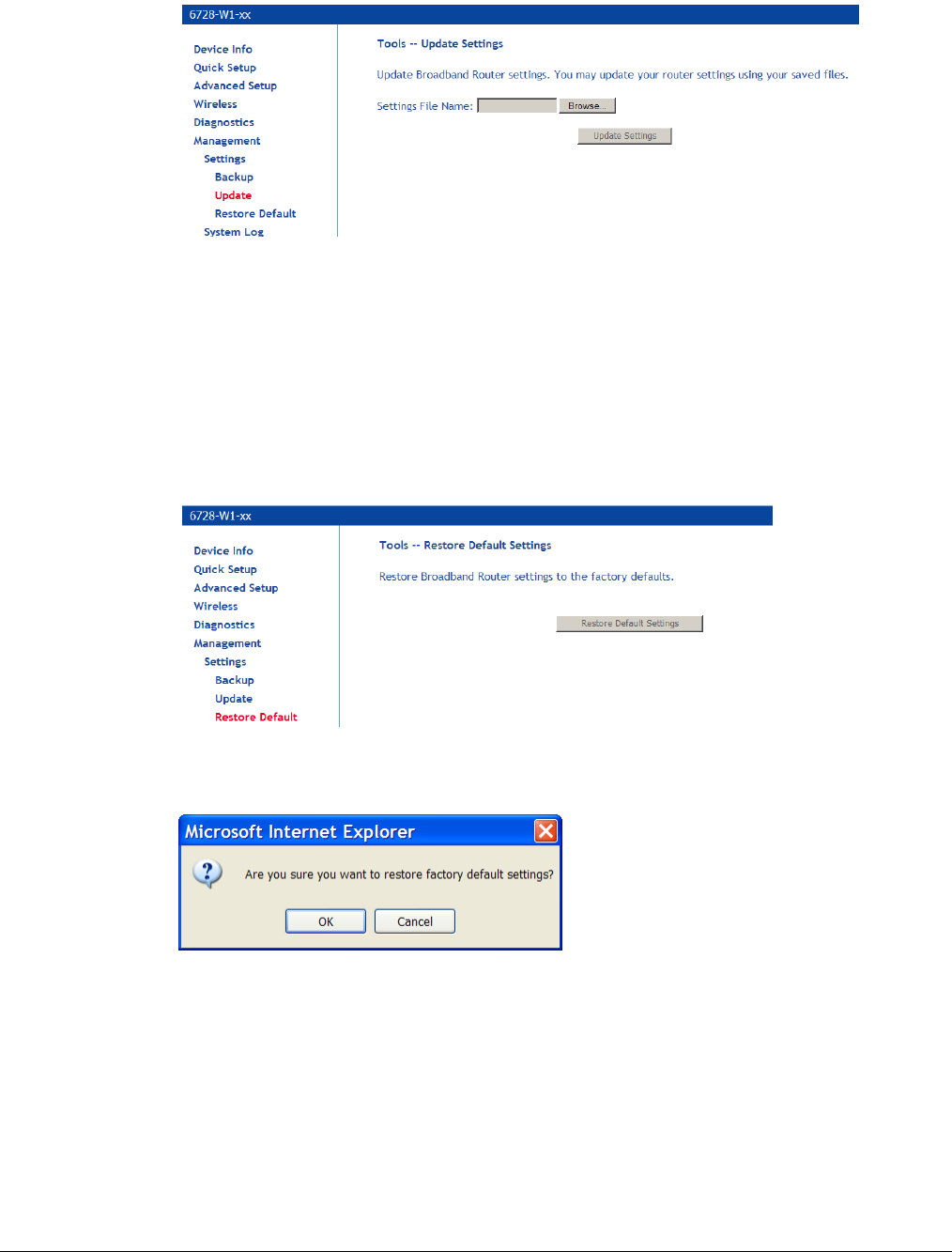
66xx/67xx Router Users Guide 160
2. Click Update Settings.
The router will restore settings and reboot to activate the restored settings.
Restore Default
Restore Default will delete all configuration changes you have made and restore the router to
factory default settings.
To restore the factory defaults:
1. From the Settings – Restore Default Settings page click Restore Default Settings.
2. Click OK when the pop-up window appears confirming that you want to restore factory
default settings to your router.
The router will restore the default settings and reboot.
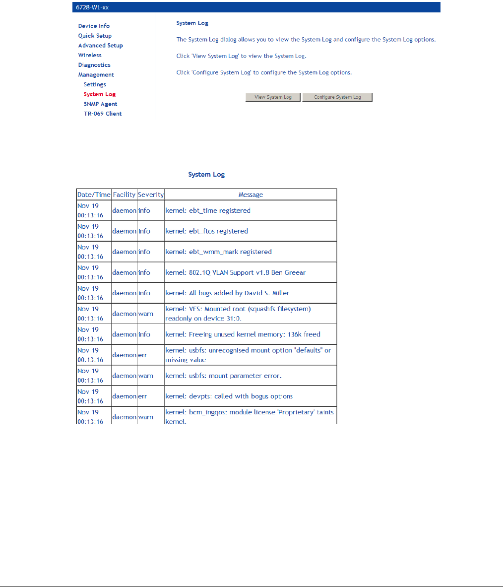
66xx/67xx Router Users Guide 161
System Log
The System Log dialog allows you to view the System Log and configure the System Log options.
To view the System Log click View System Log to check the log file.
Note: Only configure this if you are instructed by your ISP technician during troubleshooting
sessions.
The System Log page shows the date and time of the recorded event, which facility captured the
event, the severity of the event and a message which describes the event.
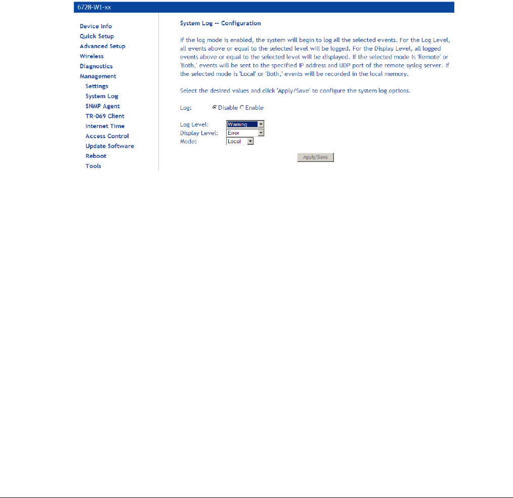
66xx/67xx Router Users Guide 162
Configure System Log
If the log is enabled, the system will log selected events based on their level. The log levels are
Emergency
Alert
Critical
Error
Warning
Notice
Informational
Debugging.
All events above or equal to the selected log level will be logged and displayed.
If the selected mode is Remote or Both, events will be sent to the specified IP address and UDP
port of a remote system log server.
If the selected mode is Local or Both, events will be recorded in the local memory.
Select the desired values and click Save/Apply button to configure the system log.
Security Log
View or clear the log for security-related events.
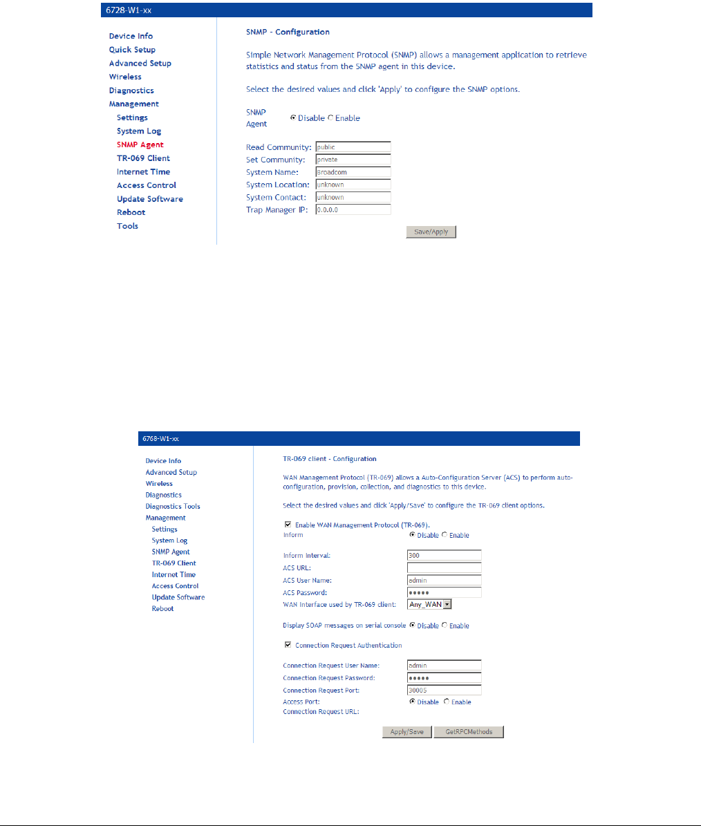
66xx/67xx Router Users Guide 163
SNMP Agent
SNMP (Simple Network Management Protocol) provides a means to monitor status and
performance as well as set configuration parameters. It enables a management station to
configure, monitor and receive trap messages from network devices.
Note: Do not change this information unless you are instructed to by your ISP technician.
TR-069 Client
The router includes a TR-069 client WAN management protocol with default values configured.
Note: Do not change this information unless you are instructed to by your ISP technician.
To enable the TR-069 client protocol:
1. Select Enable WAN Management Protocol (TR-069).
2. Click on the Save/Reboot button for the change to take place.
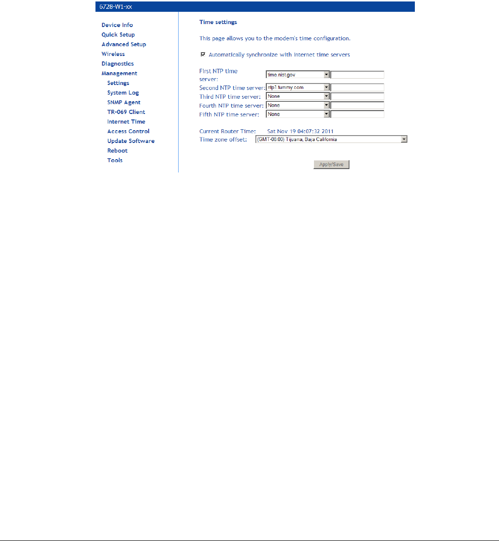
66xx/67xx Router Users Guide 164
Internet Time
Your router can synchronize its internal clock servers with servers running Network Time Protocol
(NTP).
1. To enable NTP, click Automatically synchronize with Internet time servers and enter the
NTP settings.
2. You may want to select a different NTP server or time zone.
3. Click Apply / Save.
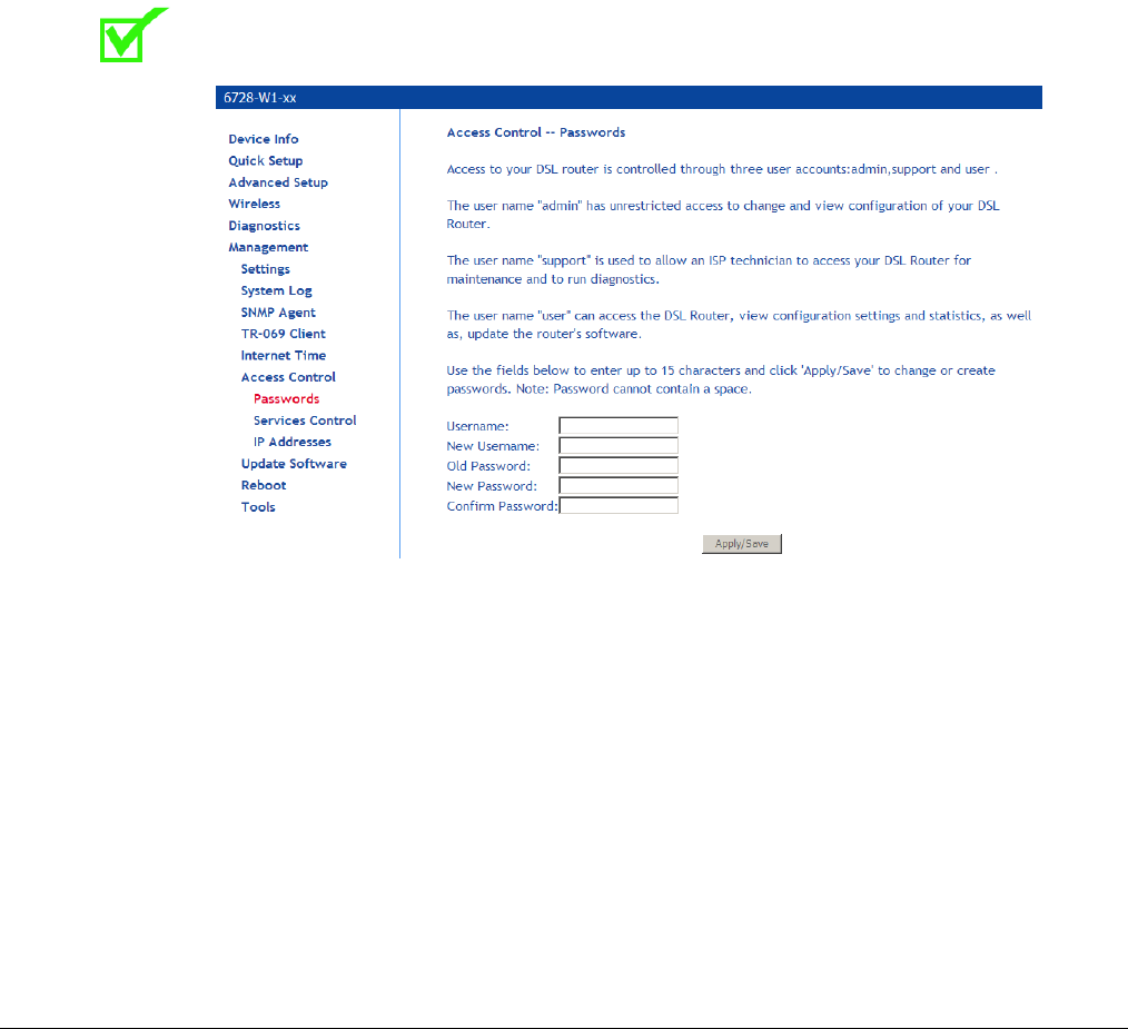
66xx/67xx Router Users Guide 165
Access Control
You can enable or disable some services of your router by LAN or WAN. If no WAN connection is
defined, only the LAN side can be configured.
Note: Do not change this information unless you are instructed to by your ISP technician.
Passwords
Access the Passwords screen under the Access Control section to change a password. Select
an account and enter the current password and the new password and then click on the Save /
Apply button.
The default username and password combinations are admin/adminXXXXXX,
support/supportXXXXXX, and user/user, where XXXXXX is printed on the label on the bottom of
the unit. These passwords are case sensitive.
Note: For security reasons you should change your password as soon as possible.
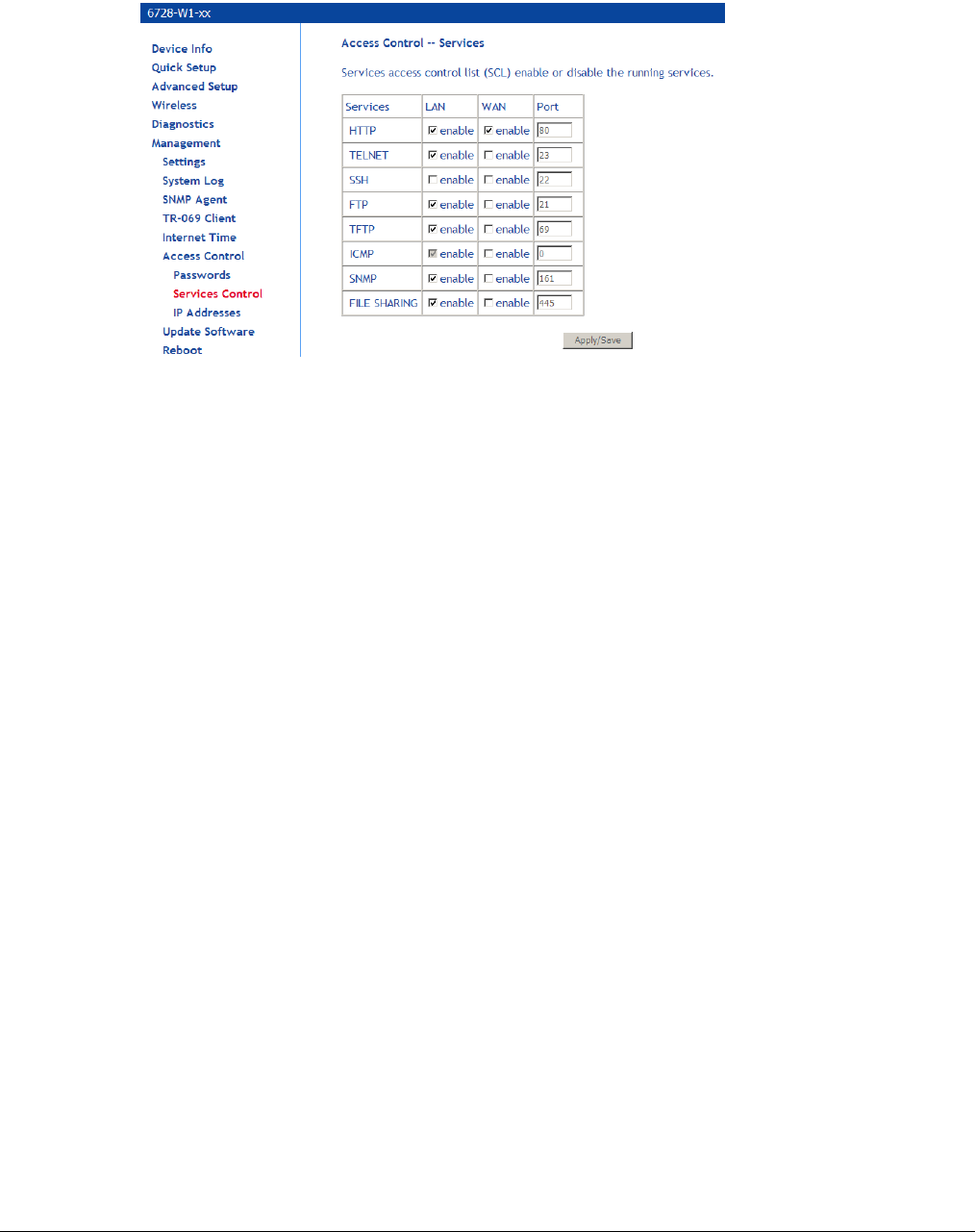
66xx/67xx Router Users Guide 166
Services Control
Note: Do not change this information unless you are instructed to by your ISP technician.
Services that can be enabled or disabled on the LAN/WAN are
• FTP
• HTTP
• ICMP
• SNMP
• SSH
• Telnet
• TFTP
• File Sharing
Enabling the WAN option allows the USB shared disk to be accessible from the WAN. You
may need to know the WAN IP address or set up as DDNS.
Note: ICMP for the LAN is always enabled. It cannot be disabled.
When the router is in bridge mode, the WAN ICMP is always enabled and cannot be changed.
The WAN ICMP service can only be configured when the modem is in routed mode (PPPoE or
IPoE).
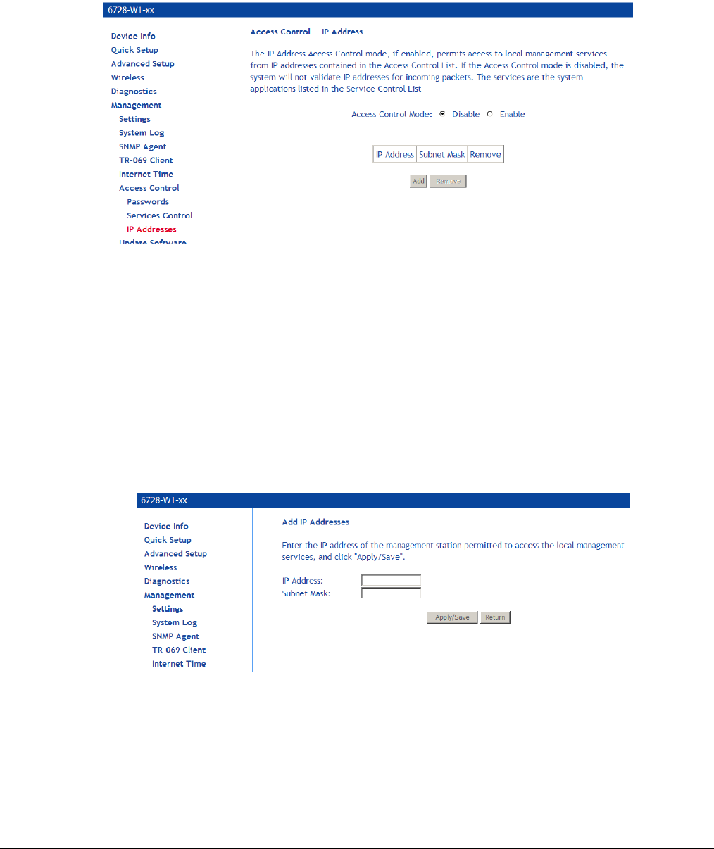
66xx/67xx Router Users Guide 167
IP Addresses
Web access to the router may be limited when Access Control Mode is enabled.
Note: Do not change this information unless you are instructed to by your ISP technician. Adding
or changing the settings on this page may cause you to lose management access to the router.
To add the IP address to the IP address list:
1. Click Add.
2. In the Add IP Addresses screen, assign the IP address of the management station that is
permitted to access the local management services, in the IP Address text box.
3. Enter the Subnet Mask.
4. Click Save / Apply.
5. In the Access Control: IP Address screen, select the IP address then select Enabled to
enable Access Control Mode.
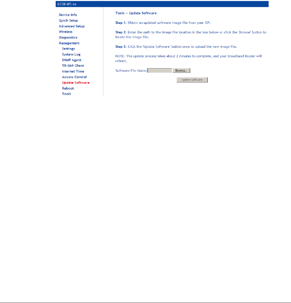
66xx/67xx Router Users Guide 168
Update Software
Note: Do not perform this operation unless you are instructed to by your ISP technician.
If your ISP releases new software for your router, follow these steps to perform an upgrade:
1. Obtain an updated software image file from your ISP.
2. Enter the path to the image file location or click on the Browse button to locate the image
file.
3. Click Update Software once (and only once) to upload the new image file.
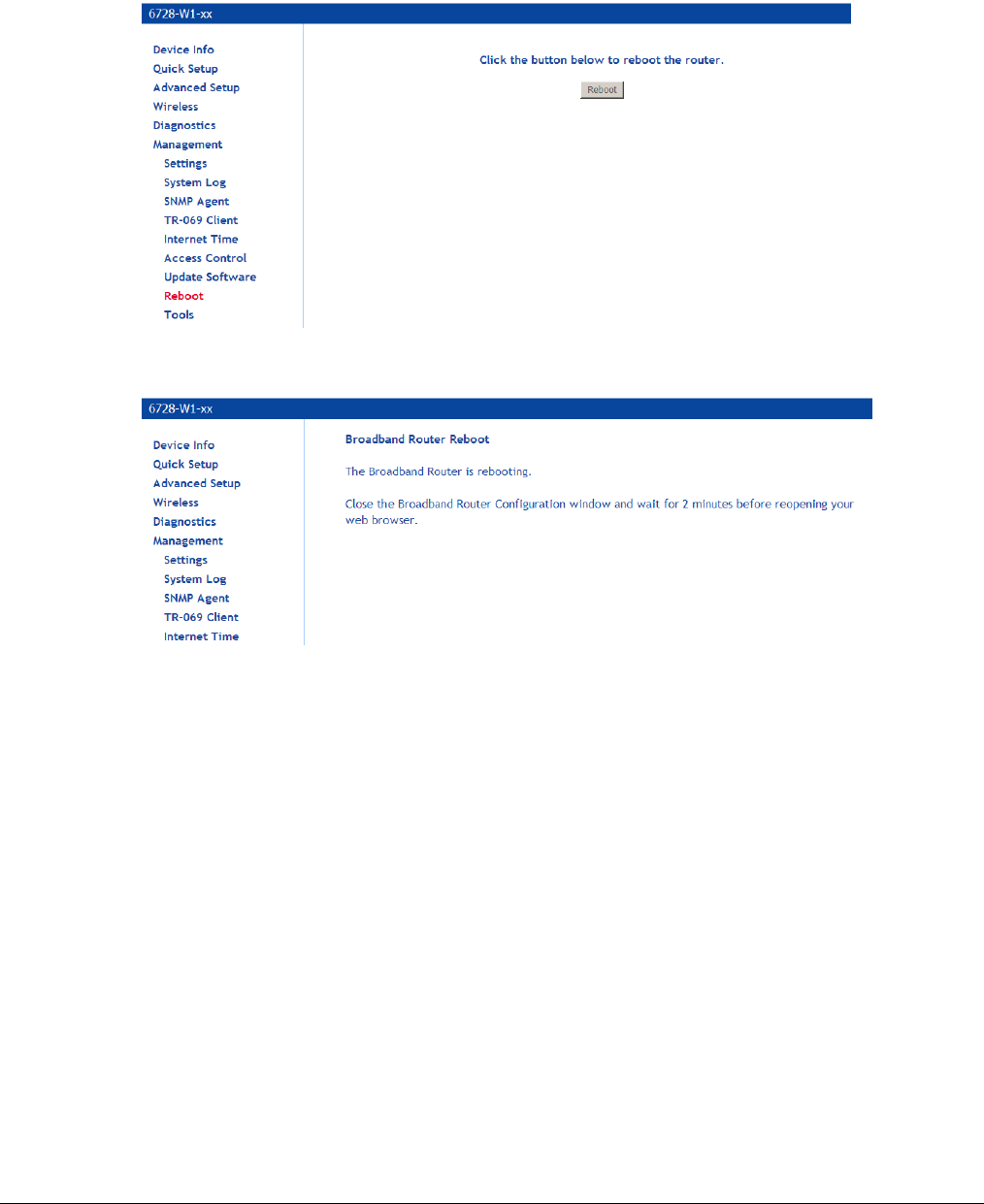
66xx/67xx Router Users Guide 169
Reboot
Clicking Save/Reboot saves all the configurations you have made, then reboots the router using
the new configuration information.
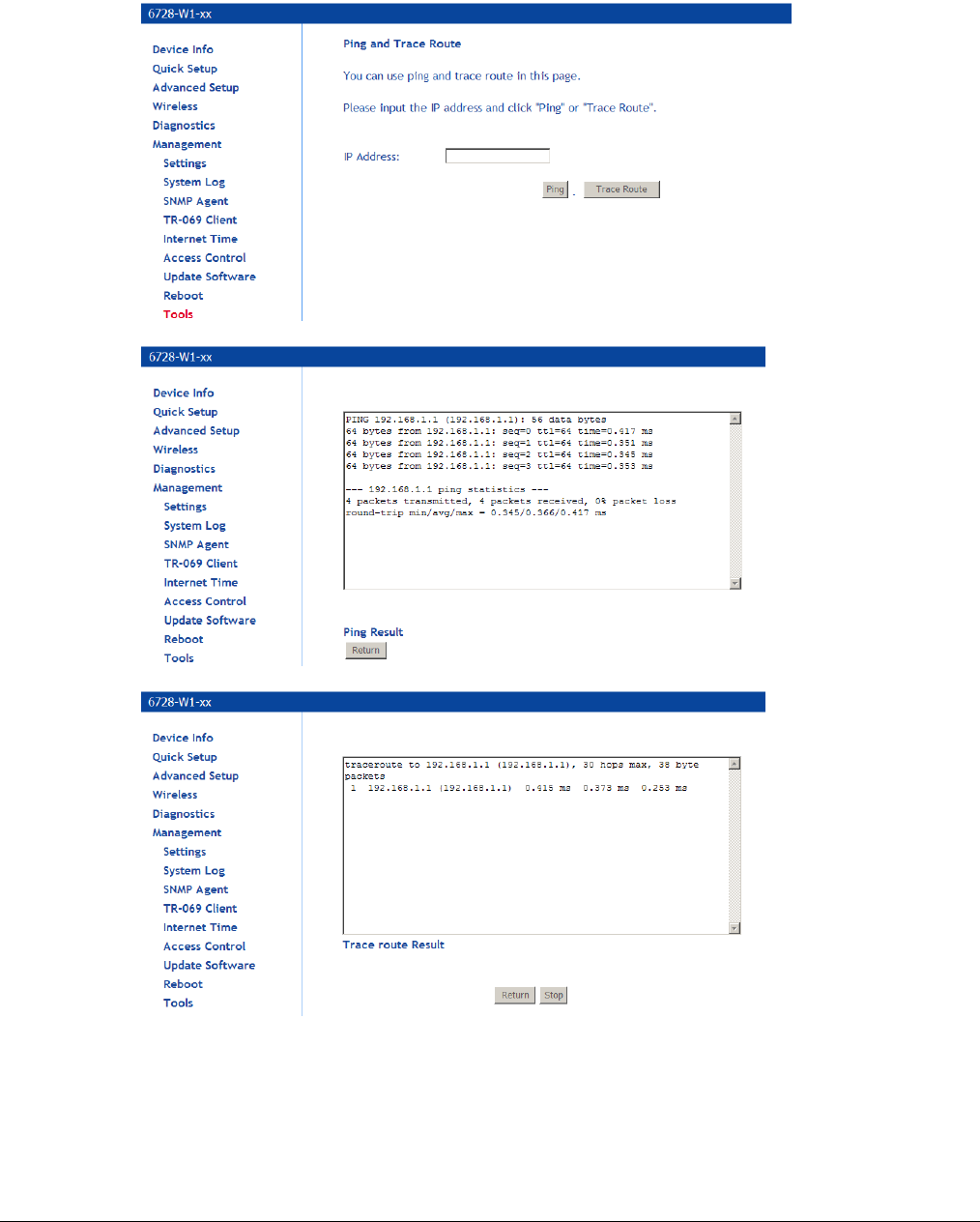
66xx/67xx Router Users Guide 170
Diagnostic Tools
The Ping and Trace Route tools may be used to verify accessibility and routes.
Start/Stop DSL

66xx/67xx Router Users Guide 171
Chapter 6 Troubleshooting
The Router Is Not Functional
1. Check to see that the power LED is green and the network cables are installed correctly.
Refer to the quick start guide for more details.
2. Check to see that the LAN and Status LEDs are green.
3. Check the settings on your PC. Again, refer to the quick start guide for more details
4. Check the router's settings.
5. From your PC, can you ping the router? Assuming that the router has DHCP enabled and
your PC is on the same subnet as the router, you should be able to ping the router.
6. Can you ping the WAN? Your ISP should have provided the IP address of their server. If you
can ping the router and your protocols are configured correctly, you should be able to ping
the ISP's network. If you cannot ping the ISP's network, make sure you are using the correct
protocols with the correct VPI/VCI values.
7. Make sure NAT is enabled if you are using private addresses on the LAN ports.
You Cannot Connect to the Router
1. Check to see that the power LED is green and that the network cables are installed correctly.
If the LED is off, make sure the router is turned on. If the LED is red, please contact your
ISP.
2. Check the Ethernet network cable is plugged in correctly. If the LAN LED does not turn
green when the Ethernet cable is connected to the router, check the cable.
3. Make sure you have connected the Ethernet port to the PC.
4. Make sure that your PC and the router are on the same network segment. The router's
default IP address is 192.168.1.1. If you are running a Windows-based PC, type ipconfig /all
(or winipcfg /all on Windows 95, 98, or ME) at a command prompt to determine the IP
address of your network adapter. Make sure that it is within the same 192.168.1.x subnet.
Your PC's subnet mask must match the router's subnet mask. The router has a default
subnet mask of 255.255.255.0.
5. If the router is in Bridge mode, you may need to set your PC to a fixed IP address within the
same subnet as the modem (i.e. 192.168.1.2)
The DSL LED Continues to Blink
This means that the DSL line is trying to train but for some reason it cannot establish a valid
connection. The likely cause of this is that you are too far away from the central office. Contact
your DSL service provider for further assistance.

66xx/67xx Router Users Guide 172
The DSL LED is Always Off
Make sure you have DSL service. You should receive notification from your ISP that DSL service
is installed. You can usually tell if the service is installed by listening to the phone line: you will
hear some high-pitched noise. If you do not hear high-pitched noise, contact your ISP.
Check to make sure the DSL cable is connected properly.
The Internet LED is Always Off
If the router is set to router mode (i.e. IPoE or IPoE or PPPoA), and the Internet LED is off, check
the modem configuration.
View the Router Summary page and see if the router is configured properly. Check the WAN
Status to make sure the link is up and the router is able to get a WAN IP address from the
network.
The Internet LED is Red
The gateway is set to routed mode but it is not able to connect to the DHCP or PPPoE:
If a wrong username/password was set in the PPP credential, user will see an error screen
instructing them of wrong password and they can re-enter the correct username/password
combination.
If the Internet LED continues to stay red, contact the ISP.
Diagnosing Problems using IP Utilities
Ping
Ping is a command you can use to check whether your PC can recognize other computers on
your network and the Internet. A ping command sends a message to the computer you specify. If
the computer receives the message, it sends messages in reply. To use it, you must know the IP
address of the computer with which you are trying to communicate.
On Windows-based computers, you can execute a ping command from the Start menu.
1. Click the Start button, and then click Run. In the Open text box, type a statement such as
the following:
ping 192.168.1.1 or the IP address you have changed
2. Click OK. You can substitute any private IP address on your LAN or a public IP address for
an Internet site, if known.
If the target computer receives the message, a Command Prompt window is displayed:

66xx/67xx Router Users Guide 173
If the target computer cannot be located, you will receive the message “Request timed out.”
Using the ping command, you can test whether the path to the device is working (using the
preconfigured default LAN IP address 192.168.1.1) or another address you assigned.
You can also test whether access to the Internet is working by typing an external address, such
as that for www.yahoo.com (216.115.108.243). If you do not know the IP address of a particular
Internet location, you can use the nslookup command, as explained in the following section.
From most other IP-enabled operating systems, you can execute the same command at a
command prompt or through a system administration utility.
Tracert
You can use the tracert command to determine the route to an external web site.
On Windows-based computers, you can execute the tracert command from the Start menu.
1. Click the Start button, and then click Run. In the Open text box, type the following:
tracert www.zhone.com
Nslookup
You can use the nslookup command to determine the IP address associated with an Internet site
name. You specify the common name, and the nslookup command looks up the name in on your
DNS server (usually located with your ISP). If that name is not an entry in your ISP’s DNS table,
the request is then referred to another higher-level server, and so on, until the entry is found. The
server then returns the associated IP address.
On Windows-based computers, you can execute the nslookup command from the Start menu.
1. Click the Start button, and then click Run. In the Open text box, type the following:
Nslookup
2. Click OK. A Command Prompt window displays with a bracket prompt (>). At the prompt,
type the name of the Internet address that you are interested in, such as
www.microsoft.com.
The window will display the associate IP address, if known, as shown below:

66xx/67xx Router Users Guide 174
There may be several addresses associated with an Internet name. This is common for web
sites that receive heavy traffic; they use multiple, redundant servers to carry the same
information.
3. To exit from the nslookup utility, type exit and press [Enter] at the command prompt.

66xx/67xx Router Users Guide 175
Appendix A – Glossary
Term Description
802.11
A family of specifications for wireless
LANs developed by a working group of the IEEE. This wireless Ethernet
protocol, often called Wi-Fi.
10BASE-T A designation for the type of wiring used by Ethernet networks with a data
rate of 10 Mbps. Also known as Category 3 (CAT 3) wiring. See data rate,
Ethernet.
100BASE-T A designation for the type of wiring used by Ethernet networks with a data
rate of 100 Mbps. Also known as Category 5 (CAT 5) wiring. See data
rate, Ethernet.
ADSL Asymmetric Digital Subscriber Line
The most commonly deployed “flavor” of DSL for home users is
asymmetrical DSL. The term asymmetrical refers to its unequal data rates
for downloading and uploading (the download rate is higher than the
upload rate). The asymmetrical rates benefit home users because they
typically download much more data from the Internet than they upload.
Analog An analog signal is a signal that has had its frequency modified in some
way, such as by amplifying its strength or varying its frequency, in order to
add information to the signal. The voice component in DSL is an analog
signal. See digital.
ATM Asynchronous Transfer Mode
A standard for high-speed transmission of data, text, voice, and video,
widely used within the Internet. ATM data rates range from 45 Mbps to 2.5
Gbps. See data rate.
Authenticate To verify a user’s identity, such as by prompting for a password.
Binary The “base two” system of numbers that uses only two digits, 0 and 1, to
represent all numbers. In binary, the number 1 is written as 1, 2 as 10, 3
as 11, 4 as 100, etc. Although expressed as decimal numbers for
convenience, IP addresses in actual use are binary numbers; e.g., the IP
address 209.191.4.240 is 11010001.10111111.00000100.11110000 in
binary. See bit, IP address, network mask.
Bit Short for “binary digit,” a bit is a number that can have two values, 0 or 1.
See binary.
Bps bits per second
Bridging Passing data from your network to your ISP and vice versa using the
hardware addresses of the devices at each location. Bridging contrasts
with routing which can add more intelligence to data transfers by using
network addresses instead. The device can perform both routing and
bridging. Typically, when both functions are enabled, the device routes IP
data and bridges all other types of data. See routing.

66xx/67xx Router Users Guide 176
Broadband A telecommunications technology that can send different types of data
over the same medium. DSL is a broadband technology.
Broadcast To send data to all computers on a network.
DHCP Dynamic Host Configuration Protocol
DHCP automates address assignment and management. When a
computer connects to the LAN, DHCP assigns it an IP address from a
shared pool of IP addresses; after a specified time limit, DHCP returns the
address to the pool.
DHCP relay Dynamic Host Configuration Protocol relay
A DHCP relay is a computer that forwards DHCP data between
computers that request IP addresses and the DHCP server that assigns
the addresses. Each of the device’s interfaces can be configured as a
DHCP relay. See DHCP.
DHCP server Dynamic Host Configuration Protocol server
A DHCP server is a computer that is responsible for assigning IP
addresses to the computers on a LAN. See DHCP.
Digital Of data, having a form based on discrete values expressed as binary
numbers (0’s and 1’s). The data component in DSL is a digital signal. See
analog.
DNS Domain Name System
The DNS maps domain names into IP addresses. DNS information is
distributed hierarchically throughout the Internet among computers called
DNS servers. For example, www.yahoo.com is the domain name
associated with IP address 216.115.108.243. When you start to access a
web site, a DNS server looks up the requested domain name to find its
corresponding IP address. If the DNS server cannot find the IP address, it
communicates with higher-level DNS servers to determine the IP address.
See domain name.
Domain name A domain name is a user-friendly name used in place of its associated IP
address. Domain names must be unique; their assignment is controlled by
the Internet Corporation for Assigned Names and Numbers (ICANN).
Domain names are a key element of URLs, which identify a specific file at
a web site. See DNS.
Download To transfer data in the downstream direction, i.e., from the Internet to the
user.
DSL Digital Subscriber Line
A technology that allows both digital data and analog voice signals to
travel over existing copper telephone lines.
Encryption keys See network keys
Ethernet The most commonly installed computer network technology, usually using
twisted pair wiring. Ethernet data rates are 10 Mbps and 100 Mbps. See
also 10BASE-T, 100BASE-T, twisted pair.
Firewall A firewall is protection between the Internet and your local network. It acts
as the firewall in your car does, protecting the interior of the car from the
engine. Your car's firewall has very small opening that allow desired
connections from the engine into the cabin (gas pedal connection, etc),

66xx/67xx Router Users Guide 177
but if something happens to your engine, you are protected.
The firewall in the router is very similar. Only the connections that you
allow are passed through the firewall. These connections normally
originate from the local network, such as users web browsing, checking e-
mail, downloading files, and playing games. However, you can allow
incoming connections so that you can run programs like a web server.
FTP File Transfer Protocol
A program used to transfer files between computers connected to the
Internet. Common uses include uploading new or updated files to a web
server, and downloading files from a web server.
Gbps Abbreviation of Gigabits per second, or one billion bits per second.
Internet data rates are often expressed in Gbps.
Host A device (usually a computer) connected to a network.
HTTP Hyper-Text Transfer Protocol
HTTP is the main protocol used to transfer data from web sites so that it
can be displayed by web browsers. See web browser, web site.
Hub A hub is a place of convergence where data arrives from one or more
directions and is forwarded out in one or more directions. It connects an
Ethernet bridge/router to a group of PCs on a LAN and allows
communication to pass between the networked devices.
ICMP Internet Control Message Protocol
An Internet protocol used to report errors and other network-related
information. The ping command makes use of ICMP.
IEEE The Institute of Electrical and Electronics Engineers is a technical
professional society that fosters the development of standards that often
become national and international standards.
Internet The global collection of interconnected networks used for both private and
business communications.
Intranet A private, company-internal network that looks like part of the Internet
(users access information using web browsers), but is accessible only by
employees.
IP See TCP/IP.
IP address Internet Protocol address
The address of a host (computer) on the Internet, consisting of four
numbers, each from 0 to 255, separated by periods, e.g., 209.191.4.240.
An IP address consists of a network ID that identifies the particular
network the host belongs to, and a host ID uniquely identifying the host
itself on that network. A network mask is used to define the network ID
and the host ID. Because IP addresses are difficult to remember, they
usually have an associated domain name that can be specified instead.
See domain name, network mask.
ISP Internet Service Provider
A company that provides Internet access to its customers, usually for a
fee.

66xx/67xx Router Users Guide 178
LAN Local Area Network.
A network limited to a small geographic area, such as a home or small
office.
LED Light Emitting Diode
An electronic light-emitting device. The indicator lights on the front of the
device are LEDs.
MAC address Media Access Control address
The permanent hardware address of a device, assigned by its
manufacturer. MAC addresses are expressed as six pairs of hex
characters, with each pair separated by colons. For example;
NN:NN:NN:NN:NN:NN.
Mask See network mask.
Mbps Abbreviation for Megabits per second, or one million bits per second.
Network data rates are often expressed in Mbps.
NAT Network Address Translation
A service performed by many routers that translates your network’s
publicly known IP address into a private IP address for each computer on
your LAN. Only your router and your LAN know these addresses; the
outside world sees only the public IP address when talking to a computer
on your LAN.
Network A group of computers that are connected together, allowing them to
communicate with each other and share resources, such as software,
files, etc. A network can be small, such as a LAN, or very large, such as
the Internet.
Network keys (Also known as encryption keys.) 64-bit and 128-bit encryption keys used
in WEP wireless security schemes. The keys encrypt data over the
WLAN, and only wireless PCs configured with WEP keys that correspond
to the keys configured on the device can send/receive encrypted data.
Network mask A network mask is a sequence of bits applied to an IP address to select
the network ID while ignoring the host ID. Bits set to 1 mean “select this
bit” while bits set to 0 mean “ignore this bit.” For example, if the network
mask 255.255.255.0 is applied to the IP address 100.10.50.1, the network
ID is 100.10.50, and the host ID is 1. See binary, IP address, subnet.
NIC Network Interface Card
An adapter card that plugs into your computer and provides the physical
interface to your network cabling. For Ethernet NICs this is typically an
RJ-45 connector. See Ethernet, RJ-45.
Packet Data transmitted on a network consists of units called packets. Each
packet contains a payload (the data), plus overhead information such as
where it came from (source address) and where it should go (destination
address).
Ping Packet Internet (or Inter-Network) Groper
A program used to verify whether the host associated with an IP address
is online. It can also be used to reveal the IP address for a given domain
name.
Port A physical access point to a device such as a computer or router, through
which data flows into and out of the device.

66xx/67xx Router Users Guide 179
PPP Point-to-Point Protocol
A protocol for serial data transmission that is used to carry IP (and other
protocol) data between your ISP and your computer. The WAN interface
on the device uses two forms of PPP called PPPoA and PPPoE. See
PPPoA, PPPoE.
PPPoA Point-to-Point Protocol over ATM
One of the two types of PPP interfaces you can define for a Virtual Circuit
(VC), the other type being PPPoE. You can define only one PPPoA
interface per VC.
PPPoE Point-to-Point Protocol over Ethernet
One of the two types of PPP interfaces you can define for a Virtual Circuit
(VC), the other type being PPPoA. You can define one or more PPPoE
interfaces per VC.
Protocol A set of rules governing the transmission of data. In order for a data
transmission to work, both ends of the connection have to follow the rules
of the protocol.
Remote In a physically separate location. For example, an employee away on
travel who logs in to the company’s intranet is a remote user.
RIP Routing Information Protocol
The original TCP/IP routing protocol. There are two versions of RIP:
version I and version II.
RJ-11 Registered Jack Standard-11
The standard plug used to connect telephones, fax machines, modems,
etc. to a telephone port. It is a 6-pin connector usually containing four
wires.
RJ-45 Registered Jack Standard-45
The 8-pin plug used in transmitting data over phone lines. Ethernet
cabling usually uses this type of connector.
Routing Forwarding data between your network and the Internet on the most
efficient route, based on the data’s destination IP address and current
network conditions. A device that performs routing is called a router.
SDNS Secondary Domain Name System (server)
A DNS server that can be used if the primary DSN server is not available.
See DNS.
Subnet A subnet is a portion of a network. The subnet is distinguished from the
larger network by a subnet mask that selects some of the computers of
the network and excludes all others. The subnet’s computers remain
physically connected to the rest of the parent network, but they are
treated as though they were on a separate network. See network mask.
Subnet mask A mask that defines a subnet. See network mask.
TCP See TCP/IP.
TCP/IP Transmission Control Protocol/Internet Protocol
The basic protocols used on the Internet. TCP is responsible for dividing
data up into packets for delivery and reassembling them at the
destination, while IP is responsible for delivering the packets from source
to destination. When TCP and IP are bundled with higher-level
applications such as HTTP, FTP, Telnet, etc., TCP/IP refers to this whole

66xx/67xx Router Users Guide 180
suite of protocols.
Telnet An interactive, character-based program used to access a remote
computer. While HTTP (the web protocol) and FTP only allow you to
download files from a remote computer, Telnet allows you to log into and
use a computer from a remote location.
TFTP Trivial File Transfer Protocol
A protocol for file transfers, TFTP is easier to use than File Transfer
Protocol (FTP) but not as capable or secure.
TKIP Temporal Key Integrity Protocol (TKIP) provides WPA with a data
encryption function. It ensures that a unique master key is generated for
each packet, supports message integrity and sequencing rules and
supports re-keying mechanisms.
Triggers Triggers are used to deal with application protocols that create separate
sessions. Some applications, such as NetMeeting, open secondary
connections during normal operations, for example, a connection to a
server is established using one port, but data transfers are performed on
a separate connection. A trigger tells the device to expect these
secondary sessions and how to handle them.
Once you set a trigger, the embedded IP address of each incoming
packet is replaced by the correct host address so that NAT can translate
packets to the correct destination. You can specify whether you want to
carry out address replacement, and if so, whether to replace addresses
on TCP packets only, UDP packets only, or both.
Twisted pair The ordinary copper telephone wiring used by telephone companies. It
contains one or more wire pairs twisted together to reduce inductance and
noise. Each telephone line uses one pair. In homes, it is most often
installed with two pairs. For Ethernet LANs, a higher grade called
Category 3 (CAT 3) is used for 10BASE-T networks, and an even higher
grade called Category 5 (CAT 5) is used for 100BASE-T networks. See
10BASE-T, 100BASE-T, Ethernet.
Unnumbered interfaces An unnumbered interface is an IP interface that does not have a local
subnet associated with it. Instead, it uses a router-id that serves as the
source and destination address of packets sent to and from the router.
Unlike the IP address of a normal interface, the router-id of an
unnumbered interface is allowed to be the same as the IP address of
another interface. For example, the WAN unnumbered interface of your
device uses the same IP address of the LAN interface (192.168.1.1).
The unnumbered interface is temporary – PPP or DHCP will assign a
‘real’ IP address automatically.
Upstream The direction of data transmission from the user to the Internet.
VC Virtual Circuit
A connection from your DSL router to your ISP.
VCI Virtual Circuit Identifier
Together with the Virtual Path Identifier (VPI), the VCI uniquely identifies a
VC. Your ISP will tell you the VCI for each VC they provide. See VC.
VDSL Very High Speed Digital Subscriber Line
It provides faster transmission rate and is capable of supporting high
bandwidth applications like IPTV and bandwidth consumed applications.

66xx/67xx Router Users Guide 181
VPI Virtual Path Identifier
Together with the Virtual Circuit Identifier (VCI), the VPI uniquely identifies
a VC. Your ISP will tell you the VPI for each VC they provide. See VC.
WAN Wide Area Network
Any network spread over a large geographical area, such as a country or
continent. With respect to the device, WAN refers to the Internet.
Web browser A software program that uses Hyper-Text Transfer Protocol (HTTP) to
download information from (and upload to) web sites, and displays the
information, which may consist of text, graphic images, audio, or video, to
the user. Web browsers use Hyper-Text Transfer Protocol (HTTP).
Popular web browsers include Netscape Navigator and Microsoft Internet
Explorer. See HTTP, web site, WWW.
Web page A web site file typically containing text, graphics and hyperlinks (cross-
references) to the other pages on that web site, as well as to pages on
other web sites. When a user accesses a web site, the first page that is
displayed is called the home page. See hyperlink, web site.
Web site A computer on the Internet that distributes information to (and gets
information from) remote users through web browsers. A web site typically
consists of web pages that contain text, graphics, and hyperlinks. See
hyperlink, web page.
WEP Wired Equivalent Privacy (WEP) encrypts data over WLANs. Data is
encrypted into blocks of either 64 bits length or 128 bits length. The
encrypted data can only be sent and received by users with access to a
private network key. Each PC on your wireless network must be manually
configured with the same key as your device in order to allow wireless
encrypted data transmissions. Eavesdroppers cannot access your
network if they do not know your private key. WEP is considered to be a
low security option.
Wireless Wireless is a term used to describe telecommunications in which
electromagnetic waves (rather than some form of wire) carry the signal
over part or the entire communication path. See wireless LAN.
Wireless LAN A wireless LAN (WLAN) is one in which a mobile user can connect to a
local area network (LAN) through a wireless (radio) connection. A
standard, IEEE 802.11, specifies the technologies for wireless LANs.
WPA Wi-Fi Protected Access
WPA is an initiative by the IEEE and Wi-Fi Alliance to address the security
limitations of WEP. WPA provides a stronger data encryption method
(called Temporal Key Integrity Protocol (TKIP)). It runs in a special, easy-
to-set-up home mode called Pre-Shared Key (PSK) that allows you to
manually enter a pass phrase on all the devices in your wireless network.
WPA data encryption is based on a WPA master key. The master key is
derived from the pass phrase and the network name (SSID) of the device.
It provides improved data encryption and stronger user authentication.
The mode of WPA supported on your device is called Pre-Shared Key
(PSK), which allows you to manually enter a type of key called a pass
phrase.
WWW World Wide Web
Also called (the) Web. Collective term for all web sites anywhere in the
world that can be accessed via the Internet.