DESKO RFID-DUAL-IVG Dual-Antenna-RFID-Module User Manual veriCLASS VP3500 Reader Board HW Specification
DESKO GmbH Dual-Antenna-RFID-Module veriCLASS VP3500 Reader Board HW Specification
UserManual.wiki
>
DESKO
>
RFID DUAL IVG User Manual
User Manual
Navigation menu
Upload a User Manual
Namespaces
Wiki Guide
HTML
PDF
Info
Views
User Manual
Discussion / Help
Navigation

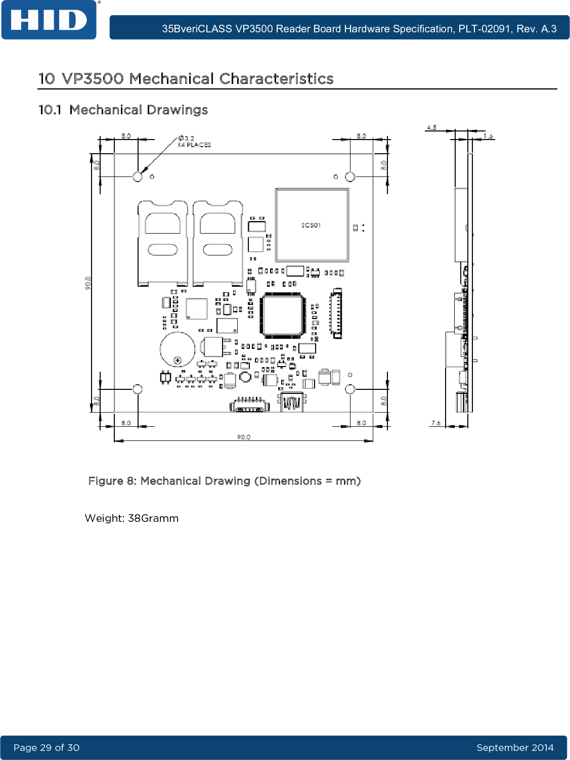
![35BveriCLASS VP3500 Reader Board Hardware Specification, PLT-02091, Rev. A.3 Page 17 of 30 September 2014 5 RF Interface The VP3500A00 reader board offers one integrated antenna compliant with the EMV Contactless requirements. The tuning is optimized for operation with ISO/IEC14443 Type A & B credentials. 5.1 Operating Field Strength The magnetic field strength was measured in accordance to ISO/IEC10373-6 (16.5MHz resonance frequency of reference PICC). The measurements were taken for a concentric arrangement between reference PICC and test PCD in four different distances. The field strength may vary slightly between different reader boards due to production tolerances. Note: Metal or ferrite material in proximity of the antenna will lead to detuning effects, which may cause major changes in the RF properties. Table 6: Field Strength Distance [mm] 2 7.5 12 20 H [A/m] 6.27 5.83 5.38 4.29 Figure 4: Operating Field Strength 1.52.53.54.55.56.57.50 5 10 15 20 25H [A/m] Distance [mm]](https://usermanual.wiki/DESKO/RFID-DUAL-IVG/User-Guide-2418863-Page-17.png)
![35BveriCLASS VP3500 Reader Board Hardware Specification, PLT-02091, Rev. A.3 September 2014 Page 18 of 4 5.2 Modulation Waveforms The measurements were taken for a concentric arrangement between reference PICC and test PCD in four different distances. The results may vary slightly between different reader boards due to production tolerances. Note: Metal or ferrite material in proximity of the antenna will lead to detuning effects, which may cause major changes in the RF properties. 5.2.1 ISO/IEC 14443 Type A Waveforms The waveforms were measured in accordance to ISO/IEC10373-6 (16.5MHz resonance frequency of reference PICC). Table 7: ISO/IEC 14443 Type A Waveforms Distance 0mm @ 106kbps Distance 7.5mm @ 106kbps t1 [ns] 2914 t1 [ns] 2913 t2 [ns] 2070 t2 [ns] 2057 t3 [ns] 438 t3 [ns] 436 t4 [ns] 236 t4 [ns] 239 Os [%] 0.35 Os [%] 0.48 Distance 12mm @ 106kbps Distance 20mm @ 106kbps t1 [ns] 2912 t1 [ns] 2915 t2 [ns] 2018 t2 [ns] 1977 t3 [ns] 442 t3 [ns] 459 t4 [ns] 244 t4 [ns] 248 Os [%] 0.36 Os [%] 0.64](https://usermanual.wiki/DESKO/RFID-DUAL-IVG/User-Guide-2418863-Page-18.png)
![35BveriCLASS VP3500 Reader Board Hardware Specification, PLT-02091, Rev. A.3 Page 19 of 30 September 2014 5.2.2 ISO/IEC 14443 Type B Waveforms The waveforms were measured in accordance to ISO/IEC10373-6 (16.5MHz resonance frequency of reference PICC). Table 8: ISO/IEC 14443 Type B Waveforms Distance 0mm @ 106kbps Distance 7.5mm @ 106kbps m [%] 11.01 m [%] 10.68 tr [ns] 389 tr [ns] 379 tf [ns] 384 tf [ns] 392 Os [%] 3.28 Os [%] 4.34 Us [%] 3.14 Us [%] 4.18 Distance 12mm @ 106kbps Distance 20mm @ 106kbps m [%] 10.55 m [%] 9.70 tr [ns] 395 tr [ns] 386 tf [ns] 427 tf [ns] 423 Os [%] 4.32 Os [%] 4.11 Us [%] 4.11 Us [%] 4.05 Note: Measured with modulation conductance setting of 33Hex (ISO/IEC 14443 Type B register #2).](https://usermanual.wiki/DESKO/RFID-DUAL-IVG/User-Guide-2418863-Page-19.png)
![35BveriCLASS VP3500 Reader Board Hardware Specification, PLT-02091, Rev. A.3 September 2014 Page 20 of 4 5.2.3 ISO/IEC 15693 Waveforms The waveforms were measured in accordance to ISO/IEC10373-6 (16.5MHz resonance frequency of reference PICC). Reader configured for 100% modulation. Table 9: ISO/IEC 15693 Waveforms Distance 0mm Distance 7.5mm tr [ns] 411 tr [ns] 408 tf [ns] 717 tf [ns] 718 Os [%] 1.06 Os [%] 0.28 Distance 12mm Distance 20mm tr [ns] 391 tr [ns] 411 tf [ns] 746 tf [ns] 781 Os [%] 3.68 Os [%] 1.42](https://usermanual.wiki/DESKO/RFID-DUAL-IVG/User-Guide-2418863-Page-20.png)
![35BveriCLASS VP3500 Reader Board Hardware Specification, PLT-02091, Rev. A.3 Page 21 of 30 September 2014 5.2.4 FeliCa Waveforms Table 10: FeliCa Waveforms Distance 0mm Distance 7.5mm m [%] 17.01 m [%] 16.81 tr [ns] 422 tr [ns] 431 tf [ns] 398 tf [ns] 408 Os [%] 0.00 Os [%] 0.00 Us [%] 0.05 Us [%] 0.25 Distance 12mm Distance 20mm m [%] 16.31 m [%] 15.34 tr [ns] 413 tr [ns] 411 tf [ns] 424 tf [ns] 436 Os [%] 0.00 Os [%] 0.00 Us [%] 0.70 Us [%] 0.70 Note: Measured with modulation conductance setting of 99Hex (FeliCa register #2).](https://usermanual.wiki/DESKO/RFID-DUAL-IVG/User-Guide-2418863-Page-21.png)