DESKO RFID-DUAL-IVG Dual-Antenna-RFID-Module User Manual veriCLASS VP3500 Reader Board HW Specification
DESKO GmbH Dual-Antenna-RFID-Module veriCLASS VP3500 Reader Board HW Specification
DESKO >
User Manual

veriCLASS
VP3500 Reader Board
P-Series Payment and Ticketing
Embedded Reader Platform
Hardware Specification
PLT-02091, Rev. A.3
September 2014
hidglobal.com
35BveriCLASS VP3500 Reader Board Hardware Specification, PLT-02091, Rev. A.3
September 2014 Page 2 of 4
Copyright
©2011 - 2014 HID Global Corporation/ASSA ABLOY AB.
All rights reserved. This document may not be reproduced, disseminated or republished in
any form without the prior written permission of HID Global Corporation.
Trademarks & Disclaimers
HID, HID Global, HID logo, iCLASS and veriCLASS are the trademarks or registered
trademarks of HID Global Corporation in the U.S. and other countries.
The information contained in this document is provided “AS IS” without any warranty.
HID Global hereby disclaims all warranties and conditions with regard to the information
contained herein, including all implied warranties of merchantability, fitness for a particular
purpose, title and non-infringement.
In no event shall HID Global be liable, whether in contract, tort or otherwise for any indirect,
special or consequential damages arising from the use of the information contained in this
document.
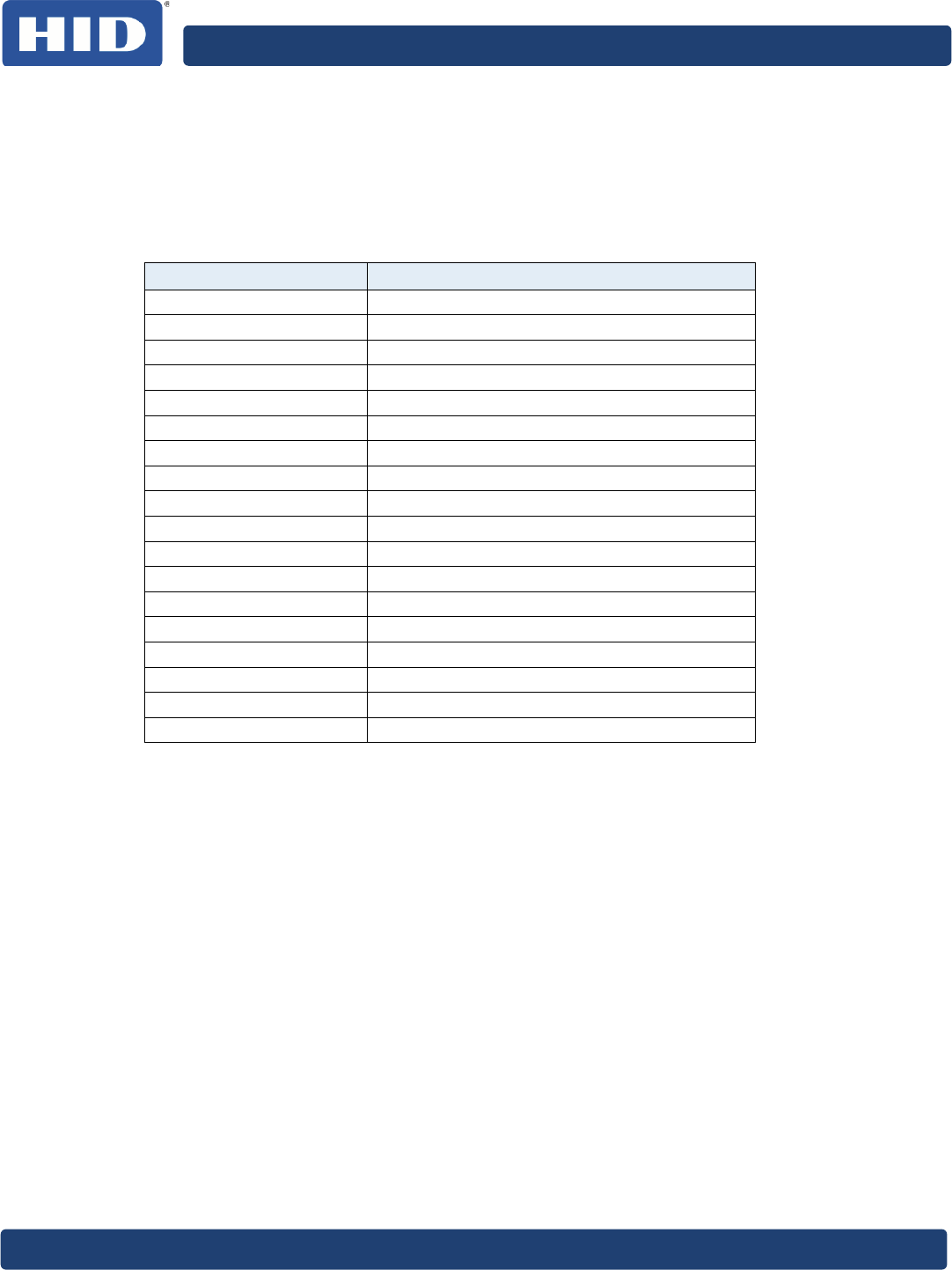
Revision History
Date
Author
Description
Version
8/21/14 RC Updated UL statement A.3
3/30/11 HP Corrected Storage Temperature in Table 1: Feature
Overview & Table 13: Absolute Maximum Ratings A.2
3/7/11 HP Added FCC, IC and CE statements A.1
2/17/11 HP Initial version A.0
Contacts
For additional offices around the world, see www.hidglobal.com corporate offices.
North America Europe, Middle East and Africa
611 Center Ridge Drive
Austin, TX 78753
USA
Phone: 866-607-7339
Fax: 949 732 2120
Haverhill Business Park Phoenix Road
Haverhill, Suffolk CB9 7AE
England
Phone: 44 (0) 1440 711 822
Fax: 44 (0) 1440 714 840
HID Global Customer Support: support.hidglobal.com

35BveriCLASS VP3500 Reader Board Hardware Specification, PLT-02091, Rev. A.3
Page 3 of 30 September 2014
Contents
Regulatory ...................................................................................................................................................................... 5
FCC / Canada Radio Certification ....................................................................................................................... 5
CE Marking .................................................................................................................................................................... 6
Reference Documents ............................................................................................................... 7
1
Introduction ........................................................................................................................... 8
1.1 Product Description ........................................................................................................................................... 8
1.2 Key Features ......................................................................................................................................................... 8
1.3 veriCLASS Platform Products ...................................................................................................................... 9
1.4 Product Guide .................................................................................................................................................... 10
1.5 Scope/Purpose ................................................................................................................................................... 11
1.6 Terms and Abbreviations ............................................................................................................................... 11
2
Overview ............................................................................................................................... 12
2.1 Features ................................................................................................................................................................ 12
2.2 Assembly Drawing ........................................................................................................................................... 13
3
Power Considerations ........................................................................................................ 14
4
Host Interfaces ..................................................................................................................... 15
4.1 USB Interface P101 ............................................................................................................................................ 15
4.2 UART Interface P104 ....................................................................................................................................... 16
5
RF Interface .......................................................................................................................... 17
5.1 Operating Field Strength .............................................................................................................................. 17
5.2 Modulation Waveforms .................................................................................................................................. 18
5.2.1 ISO/IEC 14443 Type A Waveforms .................................................................................................................. 18
5.2.2 ISO/IEC 14443 Type B Waveforms................................................................................................................... 19
5.2.3 ISO/IEC 15693 Waveforms .................................................................................................................................. 20
5.2.4 FeliCa Waveforms .................................................................................................................................................... 21
6
Contact Interfaces ............................................................................................................. 22
6.1 Assembly Drawing .......................................................................................................................................... 22
7
Visual /Audio Interface ..................................................................................................... 23
8
I/O .......................................................................................................................................... 25
9
VP3500A00 Electrical Characteristics ......................................................................... 26
9.1 Absolute Maximum Ratings ........................................................................................................................ 26
9.2 Power Supply .................................................................................................................................................... 26
9.3 Host Interfaces .................................................................................................................................................. 26
9.3.1 USB Interface (P101) ............................................................................................................................................... 26
9.3.2 UART Interface (P104) .......................................................................................................................................... 27
9.4 Contact Interfaces (P102, P103) ................................................................................................................ 27
9.5 Electrical I/O (P105) ....................................................................................................................................... 28
10
VP3500 Mechanical Characteristics ............................................................................. 29
10.1 Mechanical Drawings...................................................................................................................................... 29

35BveriCLASS VP3500 Reader Board Hardware Specification, PLT-02091, Rev. A.3
September 2014 Page 4 of 4
List of Figures
Figure 1: veriCLASS P Series Product Schematic ........................................................................................... 10
Figure 3: VP3500A00 Reader Board Assembly Drawing .......................................................................... 13
Figure 4: Mechanical Drawing USB Connector ............................................................................................... 15
Figure 5: Operating Field Strength .......................................................................................................................17
Figure 6: VP3500A00 Reader Contact Interfaces ........................................................................................22
Figure 7: veriCLASS Buzzer .................................................................................................................................... 23
Figure 8: veriCLASS LEDs (Bottom)................................................................................................................... 24
Figure 9: Mechanical Drawing (Dimensions = mm) ...................................................................................... 29
List of Tables
Table 1: Feature Overview .........................................................................................................................................12
Table 2: Power Consumptions for different Operation Modes................................................................. 14
Table 3: USB Interface ............................................................................................................................................... 15
Table 4: UART Interface ............................................................................................................................................ 16
Table 5: UART Connector ......................................................................................................................................... 16
Table 6: Field Strength ...............................................................................................................................................17
Table 7: ISO/IEC 14443 Type A Waveforms .................................................................................................... 18
Table 8: ISO/IEC 14443 Type B Waveforms..................................................................................................... 19
Table 9: ISO/IEC 15693 Waveforms .................................................................................................................... 20
Table 10: FeliCa Waveforms .....................................................................................................................................21
Table 11: UART Interface ........................................................................................................................................... 25
Table 12: I/O Connector ............................................................................................................................................ 25
Table 13: Absolute Maximum Ratings ................................................................................................................. 26
Table 14: Electrical Characteristics Power Supply ........................................................................................ 26
Table 15: Electrical Characteristics USB Interface ......................................................................................... 26
Table 16: P104 - Electrical Characteristics UART Interface ........................................................................27
Table 17: P102 - Contact Interface 1 Class A, 5V .............................................................................................27
Table 18: P102 - Contact Interface 1 Class B, 3V .............................................................................................27
Table 19: P102 - Contact Interface 1 Class B, 1.8V ...........................................................................................27
Table 20: P103- Contact Interface 2 Class A, 5V ............................................................................................27
Table 21: P103 - Contact Interface 2 Class B, 3V ........................................................................................... 28
Table 22: P103 - Contact Interface 2 Class C, 1.8V ........................................................................................ 28
Table 23: Contact Interface 1, 2 Clock ................................................................................................................ 28
Table 24: Contact Interface I/Os .......................................................................................................................... 28
Table 25: P105 - Electrical Characteristics I/Os ............................................................................................. 28

veriCLASS VP3500 Reader Board Hardware Specification, PLT-02091, Rev. A.3
Page 5 of 30 September 2014
Regulatory
FCC / Canada Radio Certification
CAUTION: Any changes or modifications to this device not explicitly
approved by manufacturer could void your authority to operate this
equipment.
This device complies with part 15 of the FCC Rules. Operation is subject to the following
two conditions: (1) This device may not cause harmful interference, and (2) this device must
accept any interference received, including interference that may cause undesired
operation.
This device complies with Industry Canada license-exempt RSS standard(s). Operation is
subject to the following two conditions:
1. This device may not cause interference, and
2. This device must accept any interference, including interference that may cause
undesired operation of the device.
The final product, containing the modular transmitter must be labeled with its own FCC ID
and IC ID. If the FCC and IC ID is not visible, when the module is installed inside another
device, then the final assembly label must contain the FCC and IC ID numbers with a
statement such as follows: “Contains Transmitter Module with FCC ID WTM-RFID-DUAL-
IVG”.
Class B Statement:
This equipment has been tested and found to comply with the limits for a Class B digital
device, pursuant to part 15 of the FCC Rules. These limits are designed to provide
reasonable protection against harmful interference in a residential installation. This
equipment generates, uses and can radiate radio frequency energy and, if not installed and
used in accordance with the instructions, may cause harmful interference to radio
communications. However, there is no guarantee that interference will not occur in a
particular installation. If this equipment does cause harmful interference to radio or
television reception, which can be determined by turning the equipment off and on, the
user is encouraged to try to correct the interference by one or more of the following
measures:
Reorient or relocate the receiving antenna.
Increase the separation between the equipment and receiver.
Connect the equipment into an outlet on a circuit different from that to which the receiver
is connected.
Consult the dealer or an experienced radio/TV technician for help.
The OEM integrator is still responsible for the FCC compliance of the end product, which
integrates this module.
Appropriate measurements (e.g. 15 B compliance) and if applicable additional equipment
authorizations (e.g. Verification, Doc) of the host device to be addressed by the
integrator/manufacturer.

35BveriCLASS VP3500 Reader Board Hardware Specification, PLT-02091, Rev. A.3
September 2014 Page 6 of 4
CE Marking
HID Global hereby declares that these proximity readers are in compliance
with the essential requirements and other relevant provisions of Directive
1999/5/EC.
Por el presente, HID Global declara que estos lectores de proximidad cumplen con los
requisitos esenciales y otras disposiciones relevantes de la Directiva 1999/5/EC.
HID Global déclare par la présente que ces lecteurs à proximité sont conformes aux
exigences essentielles et aux autres stipulations pertinentes de la Directive 1999/5/CE.
A HID Global, por meio deste, declara que estes leitores de proximidade estão em
conformidade com as exigências essenciais e outras condições da diretiva 1999/5/EC.
HID Global bestätigt hiermit, dass die Leser die wesentlichen Anforderungen und anderen
relevanten Bestimmungen der Richtlinie 1999/5/EG erfüllen.
HID Global dichiara che i lettori di prossimità sono conformi ai requisiti essenziali e ad altre
misure rilevanti come previsto dalla Direttiva europea 1999/5/EC.
Download copies of the R&TTE Declaration of Conformity (DoC) at
http://certifications.hidglobal.com.
35BveriCLASS VP3500 Reader Board Hardware Specification, PLT-02091, Rev. A.3
Page 7 of 30 September 2014
Reference Documents
3300-901 veriCLASS Quick Start Guide
3300-911 veriCLASS DTK Application Note
3300-905 veriCLASS Antenna Design Guide (*)
3300-906 veriCLASS Hardware Specification
3300-910 veriCLASS Software Developers Guide
EMV 2000 Integrated Circuit Card Specification for Payment Systems
Version 4.2
EMV Contactless Contactless Specification for Payment Systems Version 2
FCC 47 CFR Part 15 Radio Frequency Devices
ISO/IEC 10373-6:2011 Identification Cards – Test Methods. – Part6: Proximity Cards
ISO/IEC 14443-1:2008 Proximity Cards: Physical Characteristics
ISO/IEC 14443-2:2001 Proximity Cards: Radio Frequency Power and Signal Interface
ISO/IEC 14443-
2:2001/Amd1:2005
Bit rates of fc64, fc/32 and fc/16
ISO/IEC 14443-2:2001/Amd1:2005/Cor1:2007
ISO/IEC 14443-3:2001 Proximity Cards: Initialization and Anti-collision
ISO/IEC 14443-
3:2001/Amd1:2005
Bit rates of fc/64, fc/32 and fc/16
ISO/IEC 14443-3:2001/Amd1:2005/Cor1:2006
ISO/IEC 14443-
3:2001/Amd3:2006
Handling of reserved field values
ISO/IEC 14443-4:2008 Proximity Cards: Transmission protocol
ISO/IEC 15693-1:2000 Vicinity Cards: Physical Characteristics
ISO/IEC 15693-2:2006 Vicinity Cards: Air Interface and Initialization
ISO/IEC 15693-3:2009 Vicinity Cards: Anti-collision and Transmission protocol
ISO/IEC 7813:2006 Financial transaction cards
ISO/IEC 7816-3:2006 Integrated circuit(s) cards: Electrical Interface and
Transmission Protocols
USB Universal Serial Bus Specification Revision 2.0
(*) Contact HID Global Technical Support for further information.

35BveriCLASS VP3500 Reader Board Hardware Specification, PLT-02091, Rev. A.3
September 2014 Page 8 of 4
1
Introduction
1.1
Product Description
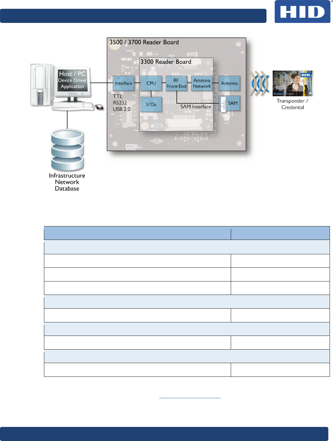
The veriCLASS® P-Series platform is a fully certified and easy-to-integrate reader product
line that provides simultaneous support for multiple card technologies as well as open and
closed loop payment schemes within one system. veriCLASS is tailored to meet the needs
of Payment and Ticketing manufacturers, such as automated fare collection systems,
handheld terminals, ATMs, vending, kiosk or retail applications. The platform offers ultimate
integration flexibility for secure contactless cashless payment and AFC solutions.
In addition, the veriCLASS platform allows developers without RF design expertise to
utilize the advantages of HID’s support. Provided are integration tools and product pre-
certification based on industry recognized standards to develop market-ready products
faster.
1.2
Key Features
• Single platform supporting
Multiple contactless card technologies (for example, MIFARE, iCLASS, FeliCa)
Multiple contactless payment protocols (for example, Calypso, EMVCo)
Multiple payment schemes (both open and closed)
• A complete flexible product line of reader modules, antennas and accessories.
• Developer tools and support. veriCLASS provides a fully featured Development Tool
Kit (DTK) providing web / desktop based tools and documentation.
• Development support from HID Global Support Services.
• Product pre-certification for industry standard bodies such as modular-FCC, CE and
EMVCo.
• Field-upgradeability giving the installer the flexibility to implement new features in
the field.
35BveriCLASS VP3500 Reader Board Hardware Specification, PLT-02091, Rev. A.3
Page 9 of 30 September 2014
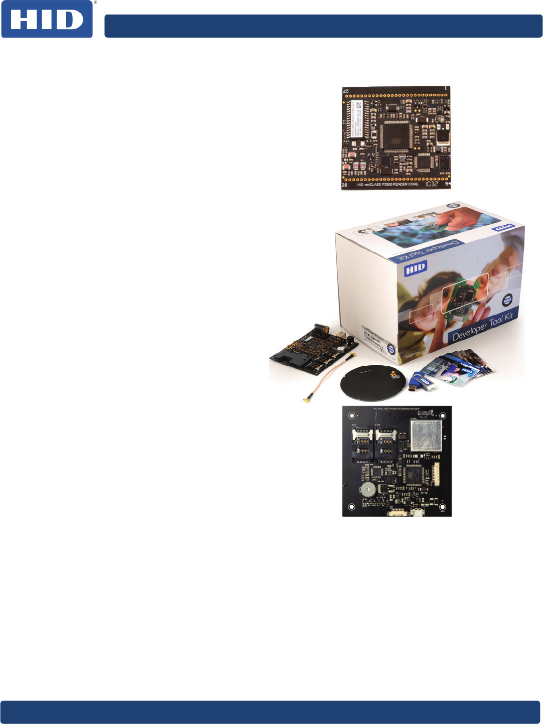
1.3
veriCLASS Platform Products
VP3300 Reader Core
• 2 RF interfaces for external
50 ohm antennas
• 4 ISO/IEC 7816 Smart Card
Interfaces
• USB / UART Connection
Development Tool Kit
• Development Board
(includes VP3300 Reader
Core)
• 2 development board
antennas (50 ohm)
• Sample Credentials.
• Memory Stick containing
development tools and
documentation
VP3500 Reader Board
• Integrated Antenna
• 2 ISO/IEC 7816 Smart Card
Sockets (ID000)
• USB / UART Connection
VP3700 Enhanced Reader Board
• Integrated Antenna
• 1 External Antenna plus option for a total of 4 external antennas
• 4 ISO/IEC 7816 Smart Card Sockets (ID000)
• 2 External ISO/IEC 7816 Smart Card Sockets (ID000/1)
• USB / UART Connection
35BveriCLASS VP3500 Reader Board Hardware Specification, PLT-02091, Rev. A.3
September 2014 Page 10 of 4
Figure 1: veriCLASS P Series Product Schematic
1.4
Product Guide
Description Part Number
Readers
HID veriCLASS P3300 Reader Core VP3300A00
HID veriCLASS P3500 Standard Reader Board VP3500A00
HID veriCLASS P3700 Enhanced Reader Board VP3700A00 *
Antenna
HID veriCLASS Antenna 4090A05 *
Antenna Cable
HID veriCLASS Antenna Cable 4091A01 *
DTK
HID veriCLASS Developer Toolkit 3134ANJ0000
* Available soon.
For further sales information contact AFC@hidglobal.com.
35BveriCLASS VP3500 Reader Board Hardware Specification, PLT-02091, Rev. A.3
Page 11 of 30 September 2014
1.5
Scope/Purpose
This document describes the hardware features of the veriCLASS P-series reader board
VP3500A00.
1.6
Terms and Abbreviations
Abbreviation Description
ANT Antenna
ARM Advanced RISC Machine
DNC Do Not Connect
EMC Electro Magnetic Compatibility
LED Light Emitting Diode
FeliCa Felicity Card
H Magnetic Field Strength
I/O Input / Output
m Modulation index
PCD Proximity Coupling Device
PICC Proximity IC Card
RF Radio Frequency
Ta Ambient Temperature
tf Fall time
TTL Transistor – Transistor Logic
tr Rise time
UART Universal Asynchronous Receiver Transmitter
USB Universal Serial Bus
35BveriCLASS VP3500 Reader Board Hardware Specification, PLT-02091, Rev. A.3
September 2014 Page 12 of 4
2
Overview
2.1
Features
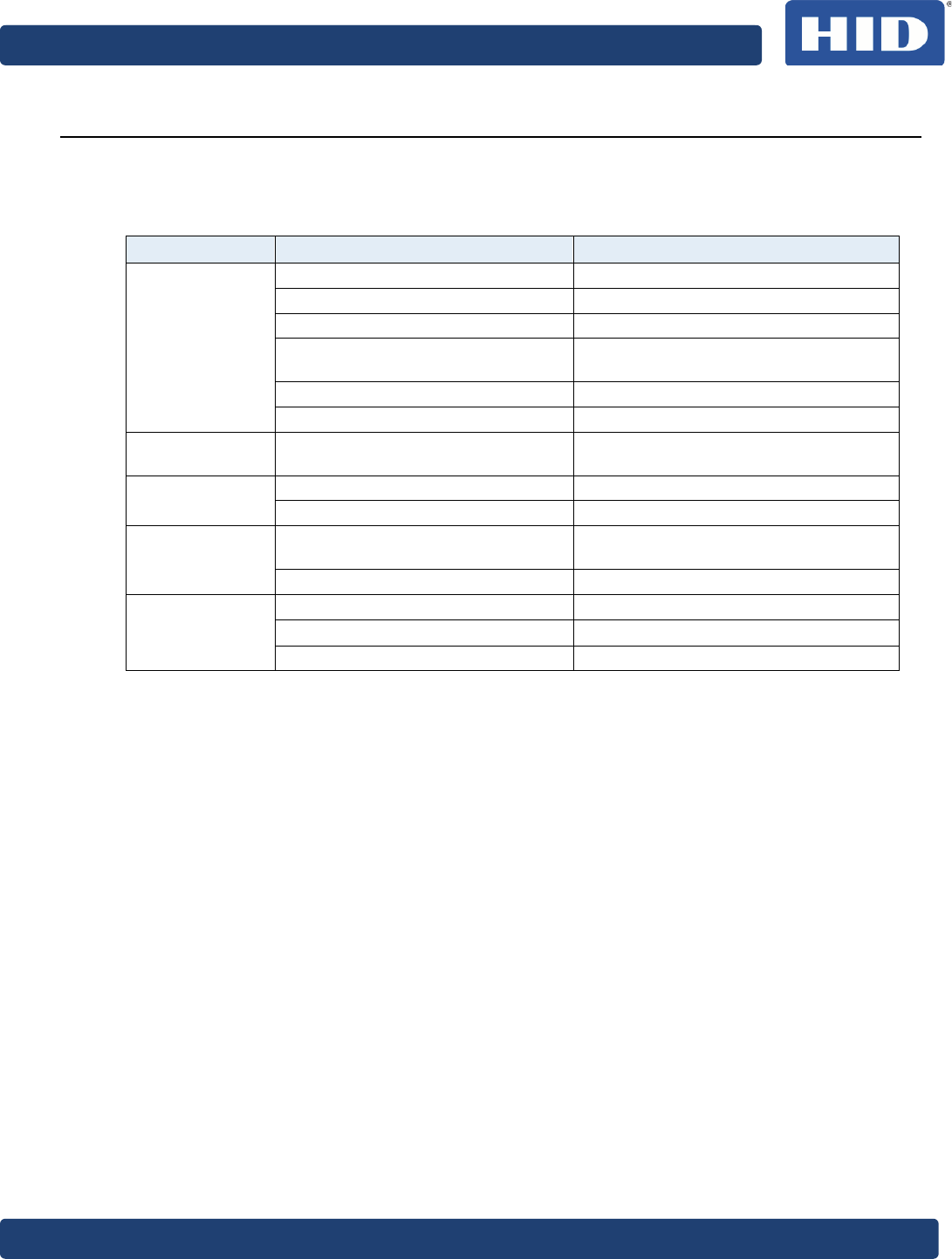
Table 1: Feature Overview
Type Feature Comment
RF Interface
ISO/IEC 14443 Type A Up to 848kbps
ISO/IEC 14443 Type B Up to 848kbps
ISO/IEC 15693
HID iCLASS Both ISO/IEC 14443 and ISO/IEC
15693 mode are supported
Sony FeliCa
One integrated antenna EMV Contactless compliant
Contact
Interfaces
Two ISO/IEC 7816 contact card
interfaces ID-000 contact card holders
Host Interfaces USB Compliant with USB 2.0 Specification
UART TTL Levels
Digital I/Os 4 LED controls EMV Contactless indication mode
supported
Buzzer Control
Environmental
Properties
Storage Temperature -40 to 80°C
Operating Temperature -25 to 85°C
Humidity 0 – 90% Non condensing
35BveriCLASS VP3500 Reader Board Hardware Specification, PLT-02091, Rev. A.3
Page 13 of 30 September 2014
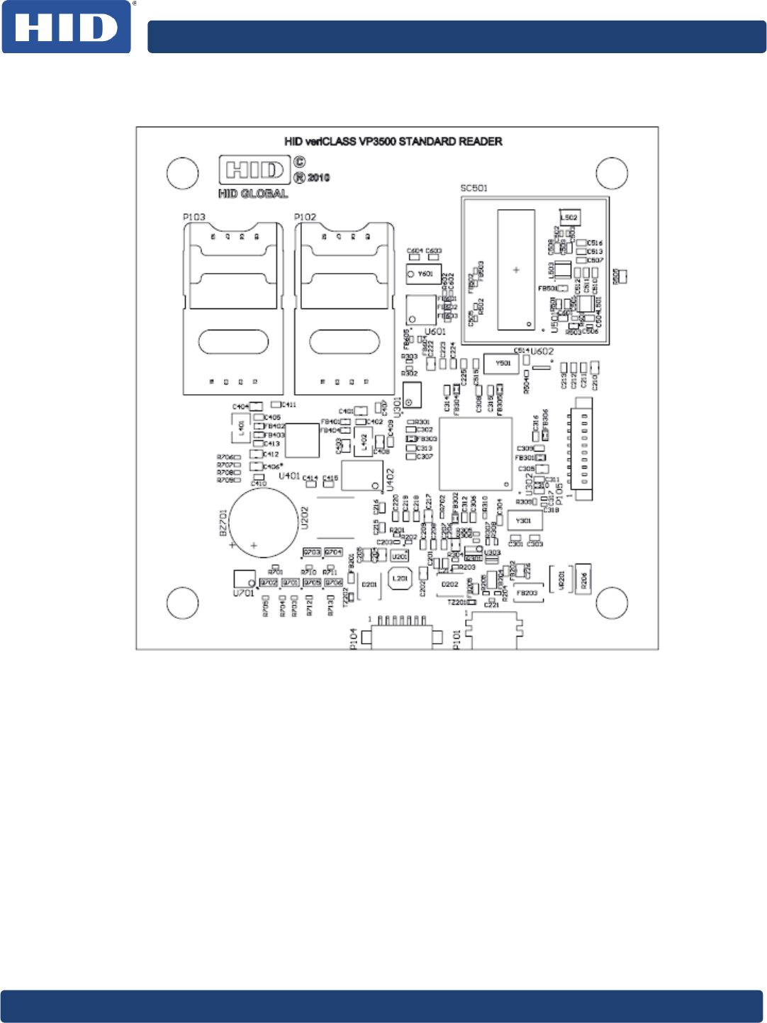
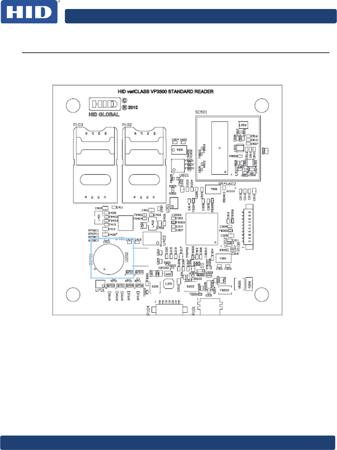
2.2
Assembly Drawing
Figure 2: VP3500A00 Reader Board Assembly Drawing
35BveriCLASS VP3500 Reader Board Hardware Specification, PLT-02091, Rev. A.3
September 2014 Page 14 of 4
3
Power Considerations
A single voltage through the USB or serial interface connector supplies the VP3500A00.
Supported is a voltage range from 3VDC to 5VDC (only through serial interface).
Note: Use only one of these two options at a time. If using USB as the host interface, use
VUSB to supply the board to ensure correct enumeration.
The VP3500A00 power consumption depends on the power consumption of the antenna.
Metal or ferrite material within the proximity of the board affects the power consumption.
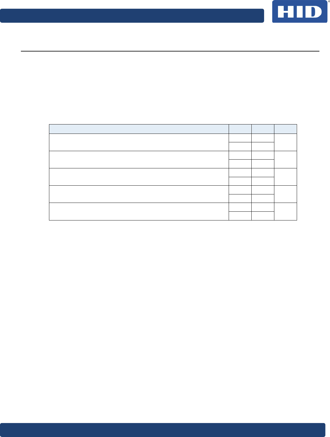
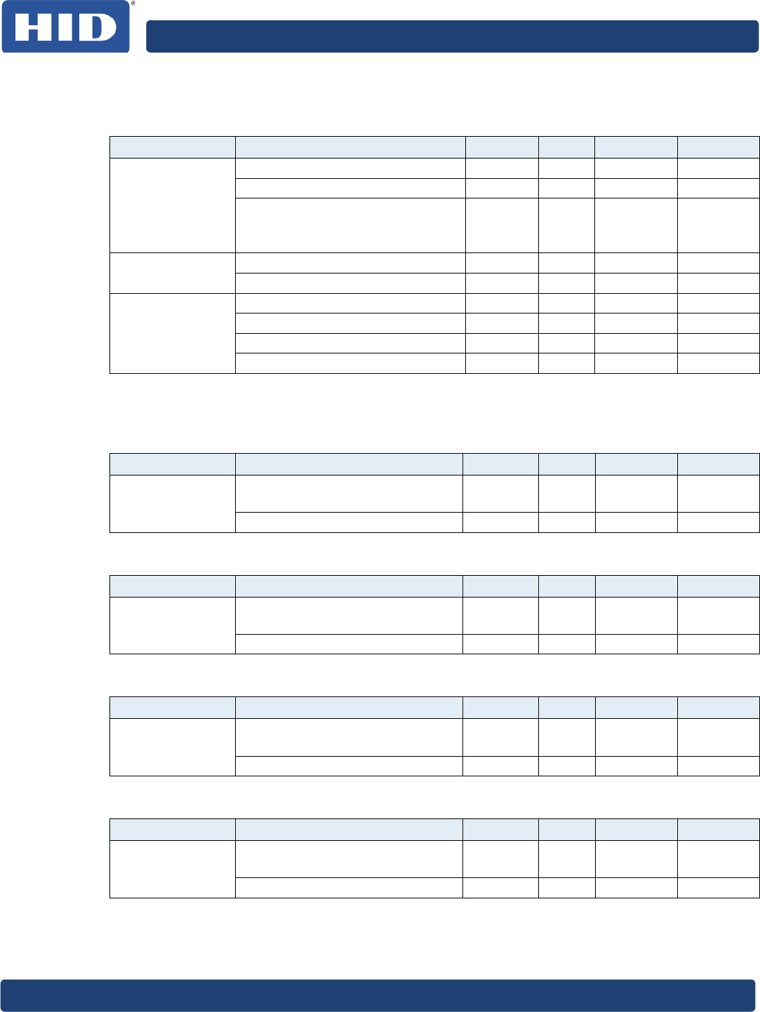
Table 2: Power Consumptions for different Operation Modes
Operation Mode Vin Typ Unit
Reader polling for cards; no contact card inserted 3V 450 mA
5V 220
Constant carrier on; no contact card inserted 3V 750 mA
5V 370
Carrier off; no contact card inserted 3V 240 mA
5V 125
RF Interface turned off; no contact card inserted 3V 165 mA
5V 100
RF interface and contact card interface turned off 3V 125 mA
5V 75
35BveriCLASS VP3500 Reader Board Hardware Specification, PLT-02091, Rev. A.3
Page 15 of 30 September 2014
4
Host Interfaces
4.1
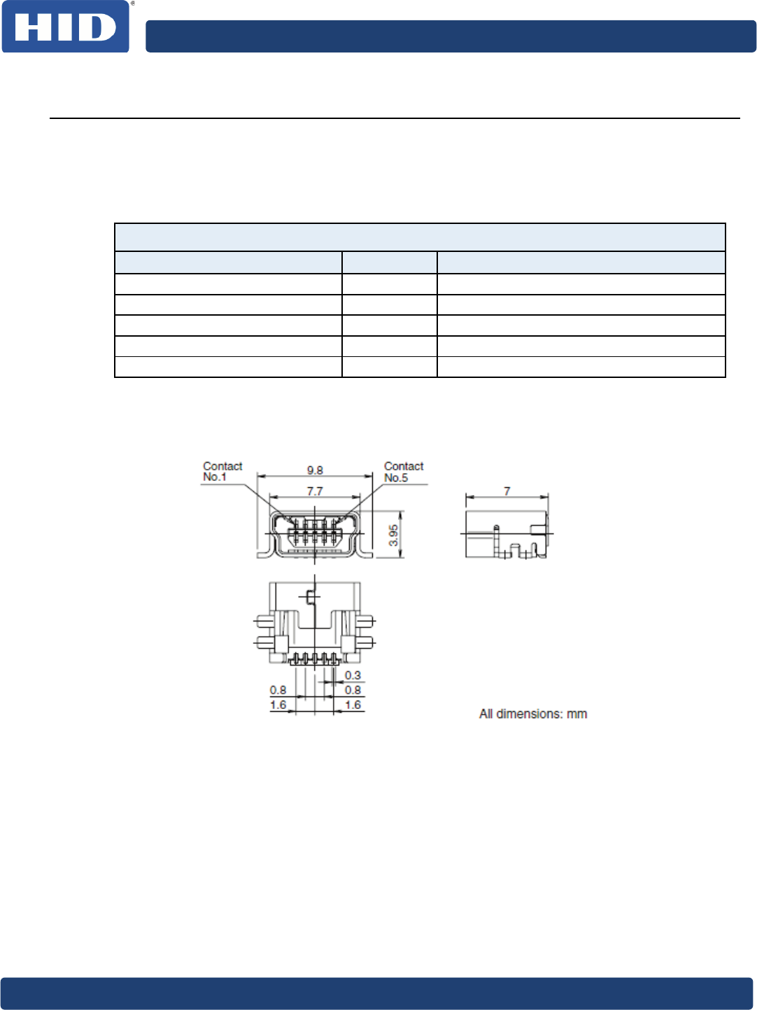
USB Interface P101
Used is a standard USB Mini-B connector (meeting the USB 2.0 Standard requirements).
Table 3: USB Interface
UART Interface
Function Signal Pin Description
VUSB 1 5VDC Bus Voltage
DM 2 Data Minus Line
DP 3 Data Plus Line
ID 4 Not Connected for Type B
GND 5 GND
Figure 3: Mechanical Drawing USB Connector
35BveriCLASS VP3500 Reader Board Hardware Specification, PLT-02091, Rev. A.3
September 2014 Page 16 of 4
4.2
UART Interface P104
Table 4: UART Interface
UART interface
Function Signal Pin Description
Vin Supply Voltage 1 Reader supply 2.5 VDC – 5.5 VDC
RX Receive Signal 2 Receive signal of the VP3500A00 (Input)
TX Transmit Signal 3 Transmit signal of the VP3500A00 (Output)
RTS Ready to Send 4 Signal line that indicates when the VP3300A00 is ready
to receive (output)
CTS Clear to Send 5 Signal line that indicates when the host is ready to receive
(input)
nRST – Reset Line 6 Signal line resets the reader (low active)
GND 7 GND
Supported are baud rates between 9600 and 460080 Baud.
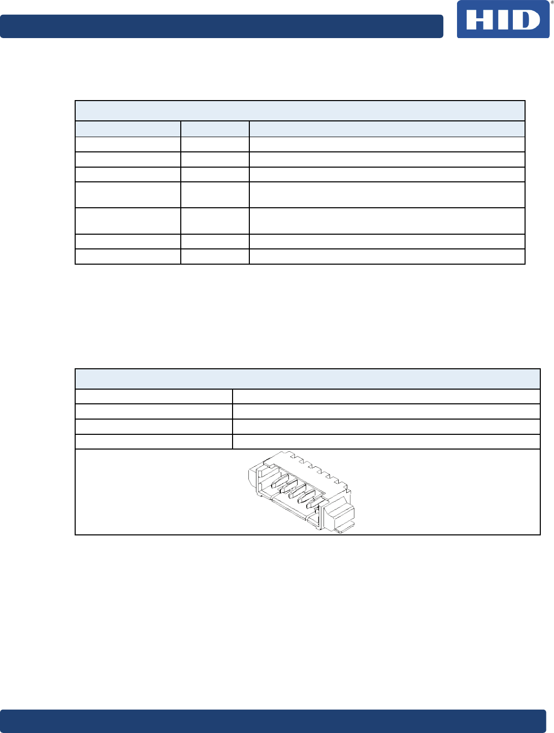
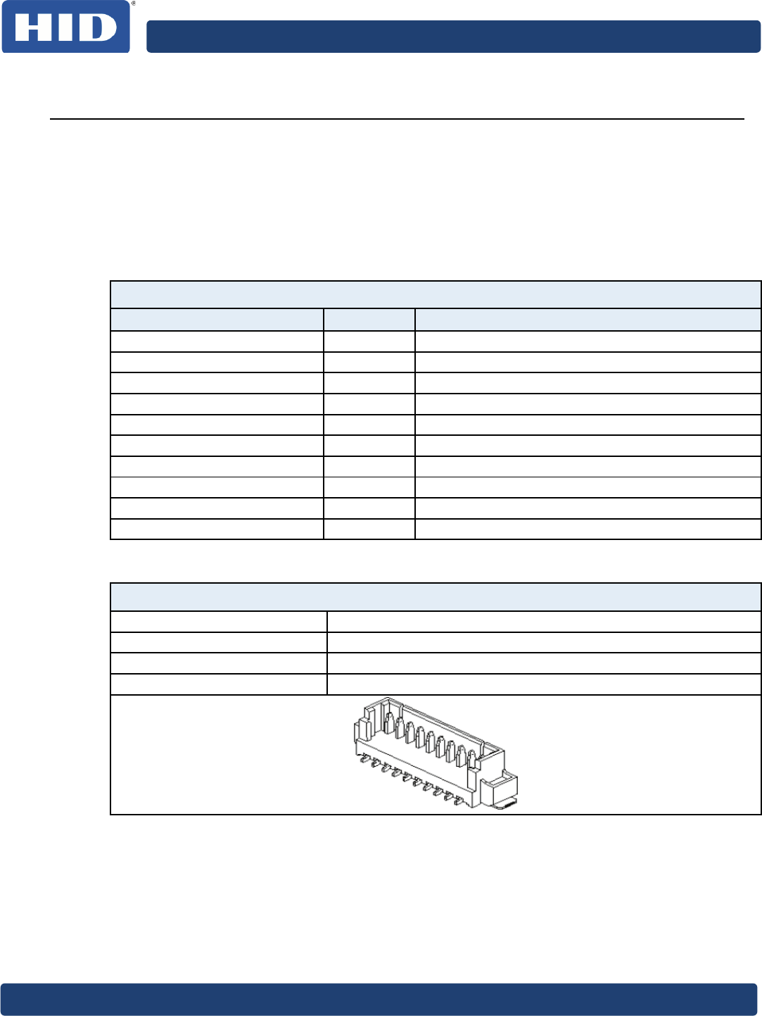
As connector a 7 way Molex PicoBlade® is used:
Table 5: UART Connector
UART interface
Manufacturer Molex
Series PicoBlade
Part Number 53261 0771
Maximum Current 1A
Image is for example only.
35BveriCLASS VP3500 Reader Board Hardware Specification, PLT-02091, Rev. A.3
Page 17 of 30 September 2014
5
RF Interface
The VP3500A00 reader board offers one integrated antenna compliant with the EMV
Contactless requirements. The tuning is optimized for operation with ISO/IEC14443 Type A
& B credentials.
5.1
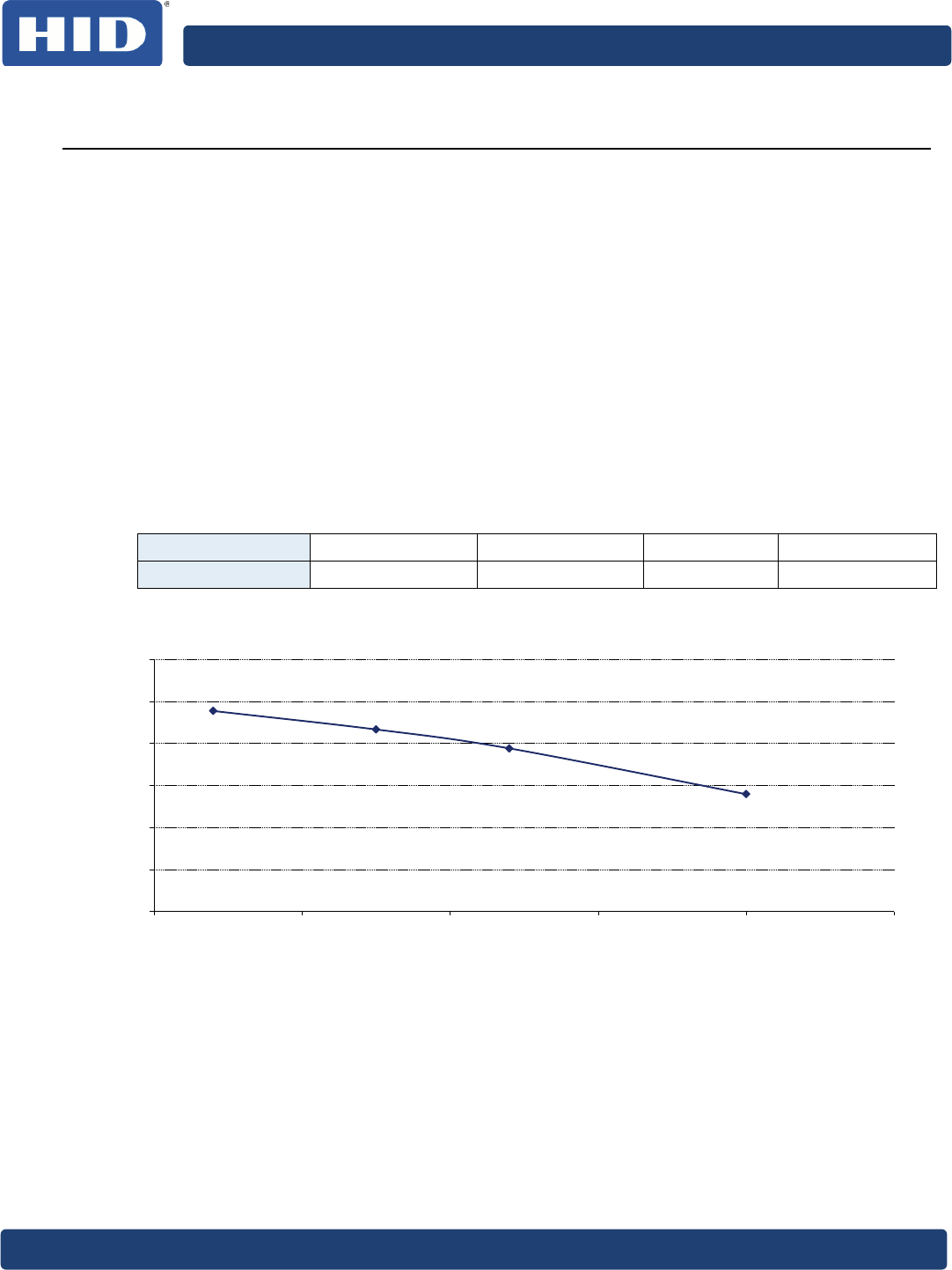
Operating Field Strength
The magnetic field strength was measured in accordance to ISO/IEC10373-6 (16.5MHz
resonance frequency of reference PICC).
The measurements were taken for a concentric arrangement between reference PICC and
test PCD in four different distances.
The field strength may vary slightly between different reader boards due to production
tolerances.
Note: Metal or ferrite material in proximity of the antenna will lead to detuning effects,
which may cause major changes in the RF properties.
Table 6: Field Strength
Distance [mm] 2 7.5 12 20
H [A/m] 6.27 5.83 5.38 4.29
Figure 4: Operating Field Strength
1.5
2.5
3.5
4.5
5.5
6.5
7.5
0 5 10 15 20 25
H [A/m]
Distance [mm]
35BveriCLASS VP3500 Reader Board Hardware Specification, PLT-02091, Rev. A.3
September 2014 Page 18 of 4
5.2
Modulation Waveforms
The measurements were taken for a concentric arrangement between reference PICC and
test PCD in four different distances.
The results may vary slightly between different reader boards due to production
tolerances.
Note: Metal or ferrite material in proximity of the antenna will lead to detuning effects,
which may cause major changes in the RF properties.
5.2.1
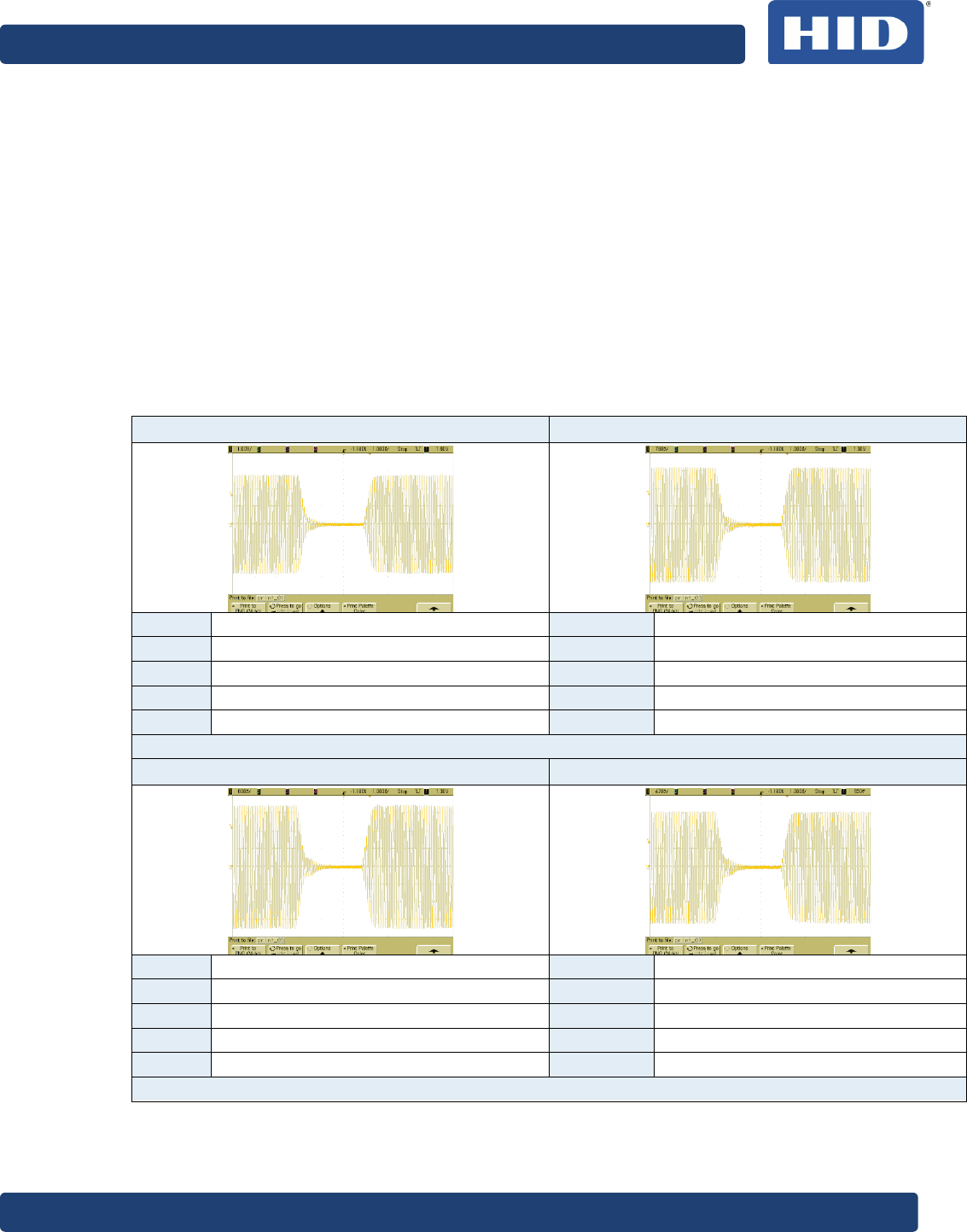
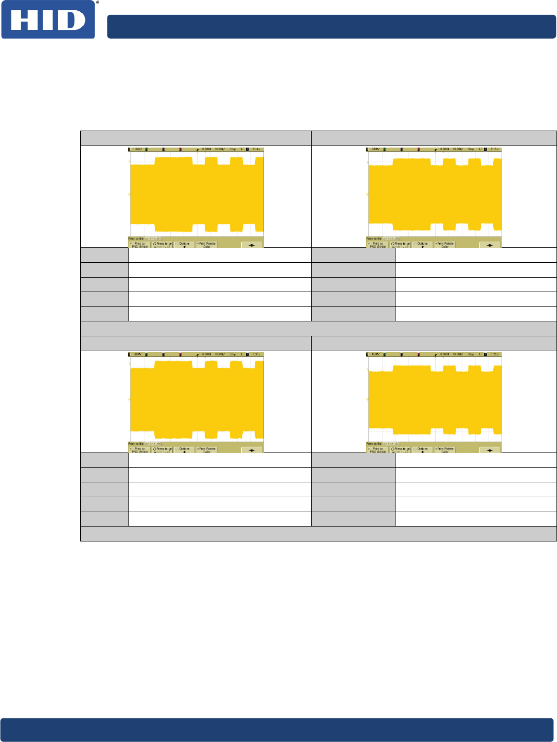
ISO/IEC 14443 Type A Waveforms
The waveforms were measured in accordance to ISO/IEC10373-6 (16.5MHz resonance
frequency of reference PICC).
Table 7: ISO/IEC 14443 Type A Waveforms
Distance 0mm @ 106kbps
Distance 7.5mm @ 106kbps
t1 [ns] 2914 t1 [ns] 2913
t2 [ns] 2070 t2 [ns] 2057
t3 [ns] 438 t3 [ns] 436
t4 [ns] 236 t4 [ns] 239
Os [%] 0.35 Os [%] 0.48
Distance 12mm @ 106kbps Distance 20mm @ 106kbps
t1 [ns] 2912 t1 [ns] 2915
t2 [ns] 2018 t2 [ns] 1977
t3 [ns] 442 t3 [ns] 459
t4 [ns] 244 t4 [ns] 248
Os [%] 0.36 Os [%] 0.64
35BveriCLASS VP3500 Reader Board Hardware Specification, PLT-02091, Rev. A.3
Page 19 of 30 September 2014
5.2.2
ISO/IEC 14443 Type B Waveforms
The waveforms were measured in accordance to ISO/IEC10373-6 (16.5MHz resonance
frequency of reference PICC).
Table 8: ISO/IEC 14443 Type B Waveforms
Distance 0mm @ 106kbps Distance 7.5mm @ 106kbps
m [%] 11.01 m [%] 10.68
tr [ns] 389 tr [ns] 379
tf [ns] 384 tf [ns] 392
Os [%] 3.28 Os [%] 4.34
Us [%] 3.14 Us [%] 4.18
Distance 12mm @ 106kbps Distance 20mm @ 106kbps
m [%] 10.55 m [%] 9.70
tr [ns] 395 tr [ns] 386
tf [ns] 427 tf [ns] 423
Os [%] 4.32 Os [%] 4.11
Us [%] 4.11 Us [%] 4.05
Note: Measured with modulation conductance setting of 33Hex (ISO/IEC 14443 Type B
register #2).
35BveriCLASS VP3500 Reader Board Hardware Specification, PLT-02091, Rev. A.3
September 2014 Page 20 of 4
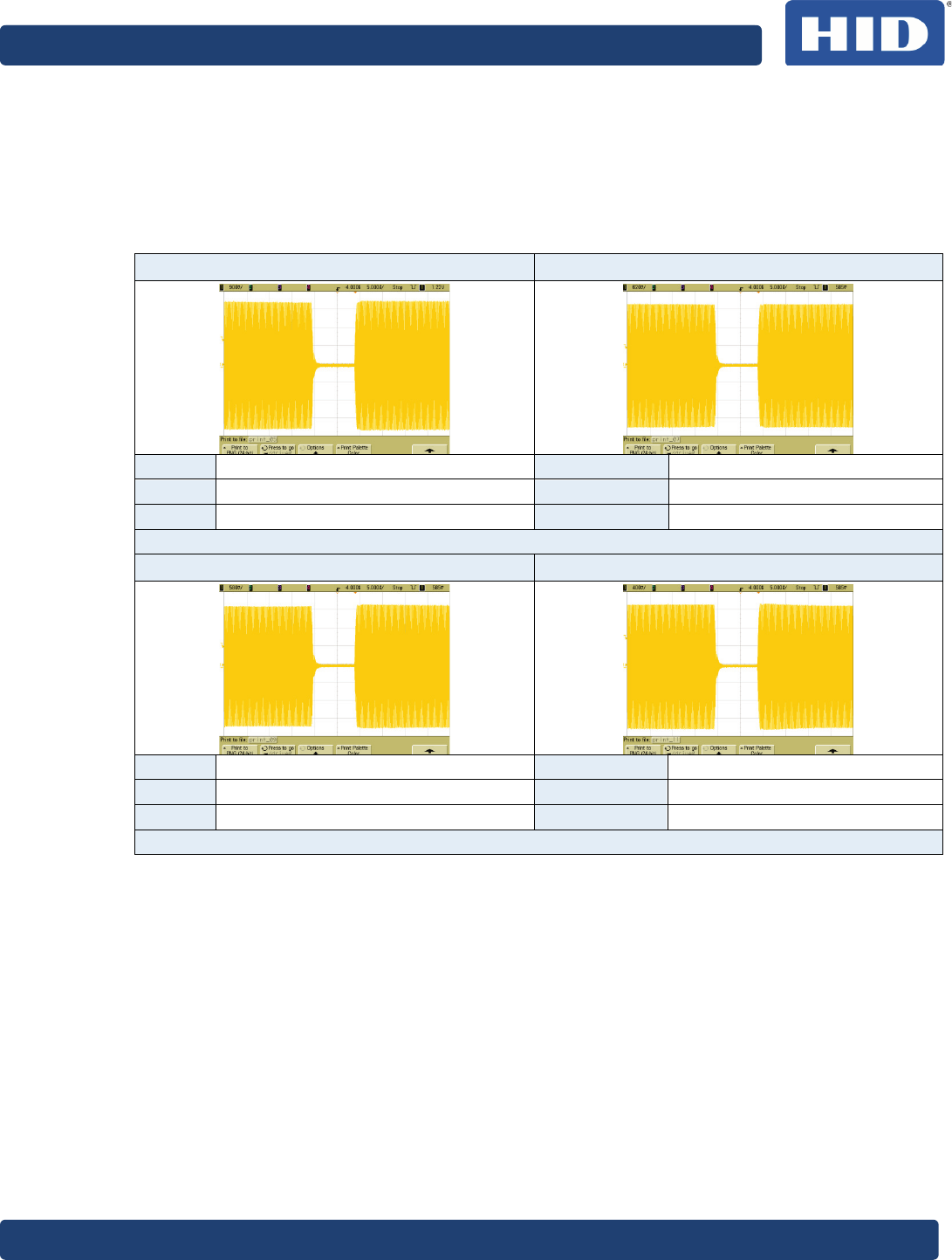
5.2.3
ISO/IEC 15693 Waveforms
The waveforms were measured in accordance to ISO/IEC10373-6 (16.5MHz resonance
frequency of reference PICC).
Reader configured for 100% modulation.
Table 9: ISO/IEC 15693 Waveforms
Distance 0mm Distance 7.5mm
tr [ns] 411 tr [ns] 408
tf [ns] 717 tf [ns] 718
Os [%] 1.06 Os [%] 0.28
Distance 12mm Distance 20mm
tr [ns] 391 tr [ns] 411
tf [ns] 746 tf [ns] 781
Os [%] 3.68 Os [%] 1.42
35BveriCLASS VP3500 Reader Board Hardware Specification, PLT-02091, Rev. A.3
Page 21 of 30 September 2014
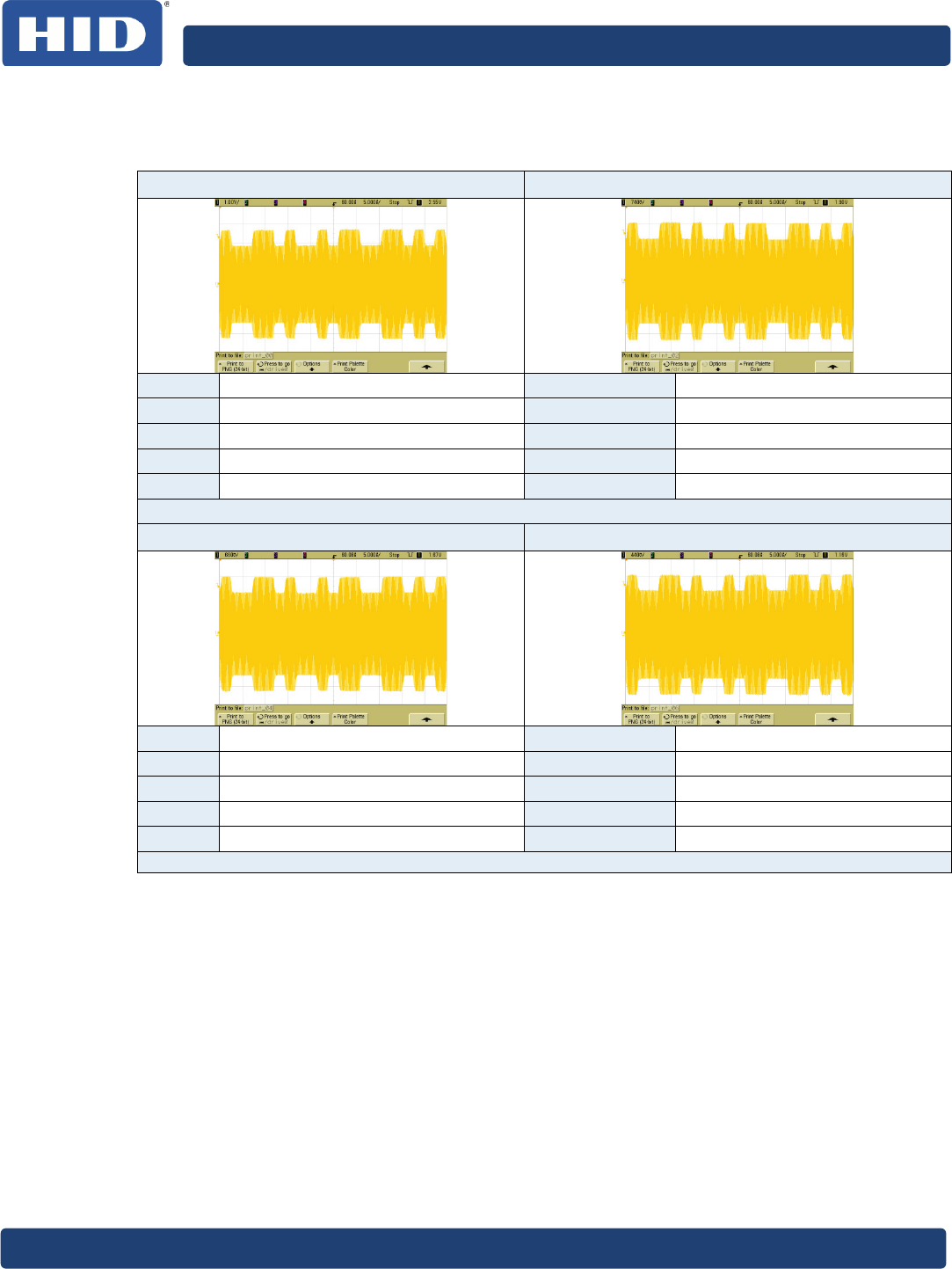
5.2.4
FeliCa Waveforms
Table 10: FeliCa Waveforms
Distance 0mm Distance 7.5mm
m [%] 17.01 m [%] 16.81
tr [ns] 422 tr [ns] 431
tf [ns] 398 tf [ns] 408
Os [%] 0.00 Os [%] 0.00
Us [%] 0.05 Us [%] 0.25
Distance 12mm Distance 20mm
m [%] 16.31 m [%] 15.34
tr [ns] 413 tr [ns] 411
tf [ns] 424 tf [ns] 436
Os [%] 0.00 Os [%] 0.00
Us [%] 0.70 Us [%] 0.70
Note: Measured with modulation conductance setting of 99Hex (FeliCa register #2).
35BveriCLASS VP3500 Reader Board Hardware Specification, PLT-02091, Rev. A.3
September 2014 Page 22 of 4
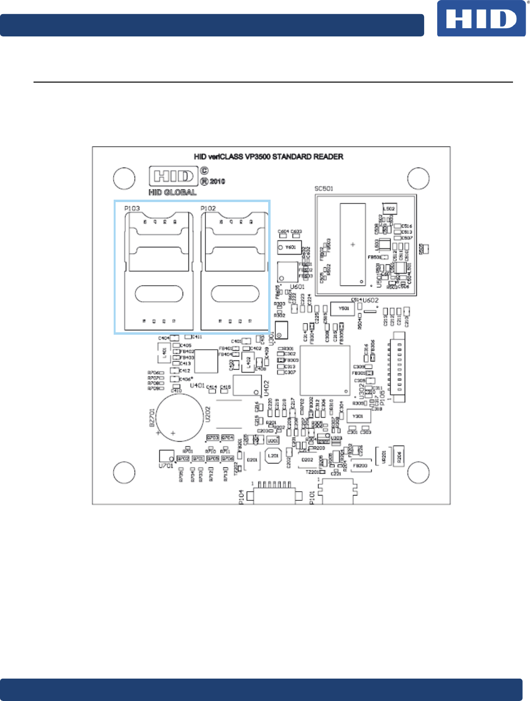
6
Contact Interfaces
The reader board provides four ISO/IEC7816 contact interfaces. Both interfaces offer ID-
000 cardholders (P102 and P103).
6.1
Assembly Drawing
Figure 5: VP3500A00 Reader Contact Interfaces
35BveriCLASS VP3500 Reader Board Hardware Specification, PLT-02091, Rev. A.3
Page 23 of 30 September 2014
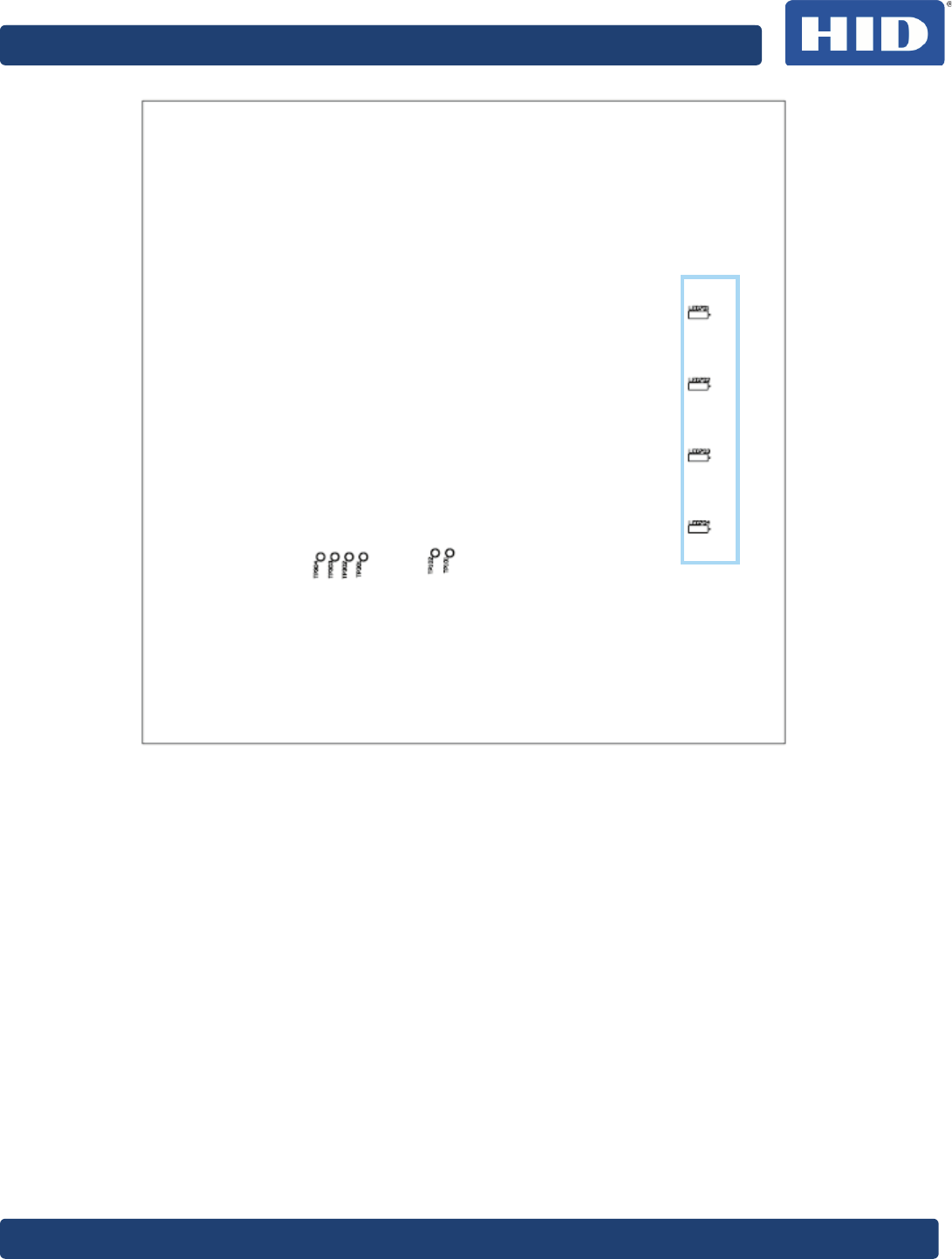
7
Visual /Audio Interface
The veriCLASS reader board offers four LEDs and one buzzer to fulfill the requirements of
the EMV Contactless specification on visual and audio interface. Both LEDs and buzzer are
fully configurable through software (for example, veriCLASS web server).
Figure 6: veriCLASS Buzzer
35BveriCLASS VP3500 Reader Board Hardware Specification, PLT-02091, Rev. A.3
September 2014 Page 24 of 4
Figure 7: veriCLASS LEDs (Bottom)
35BveriCLASS VP3500 Reader Board Hardware Specification, PLT-02091, Rev. A.3
Page 25 of 30 September 2014
8
I/O
The veriCLASS reader board offers four dedicated LED controls and one dedicated buzzer
control line (open collector). The board itself already has all LED’s and the buzzer
populated but the control lines are still available in through connector P105 in case the
visual/audio interface needs to be placed off the board.
Note: The onboard LEDs and buzzer are using the same signal lines provided by the
connector.
Table 11: UART Interface
UART Interface
Function Signal Pin Description
+5V 1 Regulated 5VDC from the reader board
LED1 2 Control line LED1
LED2 3 Control line LED2
LED3 4 Control line LED3
LED4 5 Control line LED4
Buzzer 6 Control line for Buzzer (open collector)
RFU 7 Reserved for future use
RFU 8 Reserved for future use
RFU 9 Reserved for future use
GND 10 GND
Table 12: I/O Connector
UART Interface
Manufacturer Molex
Series PicoBlade®
Part Number 053398 1071
Maximum Current 1A
Example Picture only
35BveriCLASS VP3500 Reader Board Hardware Specification, PLT-02091, Rev. A.3
September 2014 Page 26 of 4
9
VP3500A00 Electrical Characteristics
9.1
Absolute Maximum Ratings
Stresses beyond those listed under Absolute Maximum Ratings may cause permanent
damage to the device. This is a stress rating only and functional operation of the device at
these or other conditions beyond those indicated in the operational sections of this
specification are not implied. Exposure to absolute maximum rating conditions for
extended periods may affect device reliability.
Table 13: Absolute Maximum Ratings
Operating Temperature -25 to 85˚C
Storage Temperature -40 to 80˚C
Voltage on Input Pins in respect to Ground -0.3V to 5.5V
Maximum Operating Voltage 5.5V
9.2
Power Supply
Table 14: Electrical Characteristics Power Supply
Signal Parameter Min Typ Max Unit
Vin (P104) Input Voltage 2.7 5.5 V
Current Consumption at 5VDC mA
VUSB (P101) Input Voltage 4.3 5.5 V
Note: The power consumption depends on the operation mode and the supply voltage. For more details
reference 0
Power Considerations.
9.3
Host Interfaces
9.3.1
USB Interface (P101)
Table 15: Electrical Characteristics USB Interface
Signal Parameter Min Typ Max Unit
VUSB Input High-level Voltage 4.2 5.5 V
Input Low-level Voltage -0.3 0.8 V
DP, DM
Input High-level Voltage 2 5.5 V
Input Low-level Voltage -0.3 0.8 V
Output High-level Voltage 2.9 3.3 V
Output Low-level Voltage 0.2 V
35BveriCLASS VP3500 Reader Board Hardware Specification, PLT-02091, Rev. A.3
Page 27 of 30 September 2014
9.3.2
UART Interface (P104)
Table 16: P104 - Electrical Characteristics UART Interface
Signal Parameter Min Typ Max Unit
RX, CTS
Input High-level Voltage 2 5.5 V
Input Low-level Voltage -0.3 0.8 V
Input Leakage Current
Typ: Ta=25˚C
Max: Ta=85˚C
40 400 nA
TX, RTS Output High-level Voltage 2.9 3.3 V
Output Low-level Voltage 0.2 V
nRST
Input Low-level Voltage -0.15 0.15*CVCC V
Input High-level Voltage 0.7CVCC CVCC+0.5 V
Input Low-level Current 600 uA
Input Low-level Current -40 40 uA
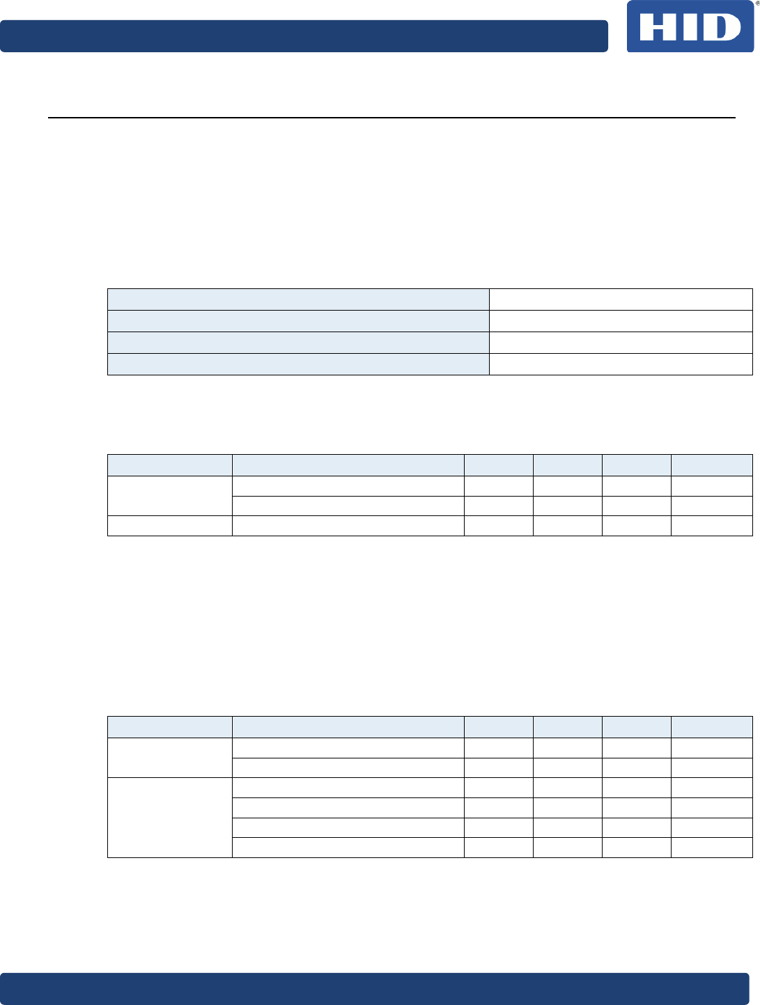
9.4
Contact Interfaces (P102, P103)
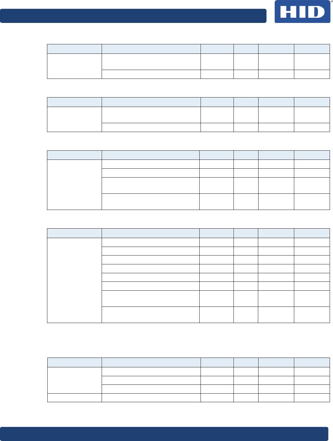
Table 17: P102 - Contact Interface 1 Class A, 5V
Signal Parameter Min Typ Max Unit
CVCC (P102)
Contact Card Voltage
Load = 60mA 4.6 5 5.4 V
Maximum Load Current 75 mA
Table 18: P102 - Contact Interface 1 Class B, 3V
Signal Parameter Min Typ Max Unit
CVCC (P102)
Contact Card Voltage
Load = 60mA 2.76 3 3.24 V
Maximum Load Current 60 mA
Table 19: P102 - Contact Interface 1 Class B, 1.8V
Signal Parameter Min Typ Max Unit
CVCC (P102)
Contact Card Voltage
Load = 35mA 1.656 1.8 1.944 V
Maximum Load Current 75 mA
Table 20: P103- Contact Interface 2 Class A, 5V
Signal
Parameter
Min
Typ
Max
Unit
CVCC (P103)
Contact Card Voltage
Load = 30mA 4.6 5 5.4 V
Maximum Load Current 70 mA
35BveriCLASS VP3500 Reader Board Hardware Specification, PLT-02091, Rev. A.3
September 2014 Page 28 of 4
Table 21: P103 - Contact Interface 2 Class B, 3V
Signal Parameter Min Typ Max Unit
CVCC (P103)
Contact Card Voltage
Load = 30mA 2.76 3 3.24 V
Maximum Load Current 70 mA
Table 22: P103 - Contact Interface 2 Class C, 1.8V
Signal Parameter Min Typ Max Unit
CVCC (P103)
Contact Card Voltage
Load = 30mA 1.656 1.8 1.944 V
Maximum Load Current 70 mA
Table 23: Contact Interface 1, 2 Clock
Signal Parameter Min Typ Max Unit
CCLK1 (P102,
P103)
Output Low-level Voltage 0.3 V
Output High-level Voltage 0.8*CVCC V
Rise Time
Cl=30pF 16 ns
Fall Time
Cl=30pF 16 Ns
Table 24: Contact Interface I/Os
Signal
Parameter
Min
Typ
Max
Unit
CIO (P102, P103)
CRST (P102,
P103)
Output Low-level Voltage 0.3 V
Output High-level Voltage 0.8*CVCC V
Input Low-level Voltage -0.15 0.15*CVCC V
Input High-level Voltage 0.7CVCC CVCC+0.5 V
Input Low-level Current 600 uA
Input Low-level Current -40 40 uA
Rise Time
Cl=30pF 100 ns
Fall Time
Cl=30pF 100 Ns
9.5
Electrical I/O (P105)
Table 25: P105 - Electrical Characteristics I/Os
Signal Parameter Min Typ Max Unit
LED1-4
Output High-level Voltage 2.9 3.3 V
Output Low-level Voltage 0.2 V
Current Draw 8 mA
Buzzer Current Draw (Open Collector) 60 mA
35BveriCLASS VP3500 Reader Board Hardware Specification, PLT-02091, Rev. A.3
Page 29 of 30 September 2014
10
VP3500 Mechanical Characteristics
10.1
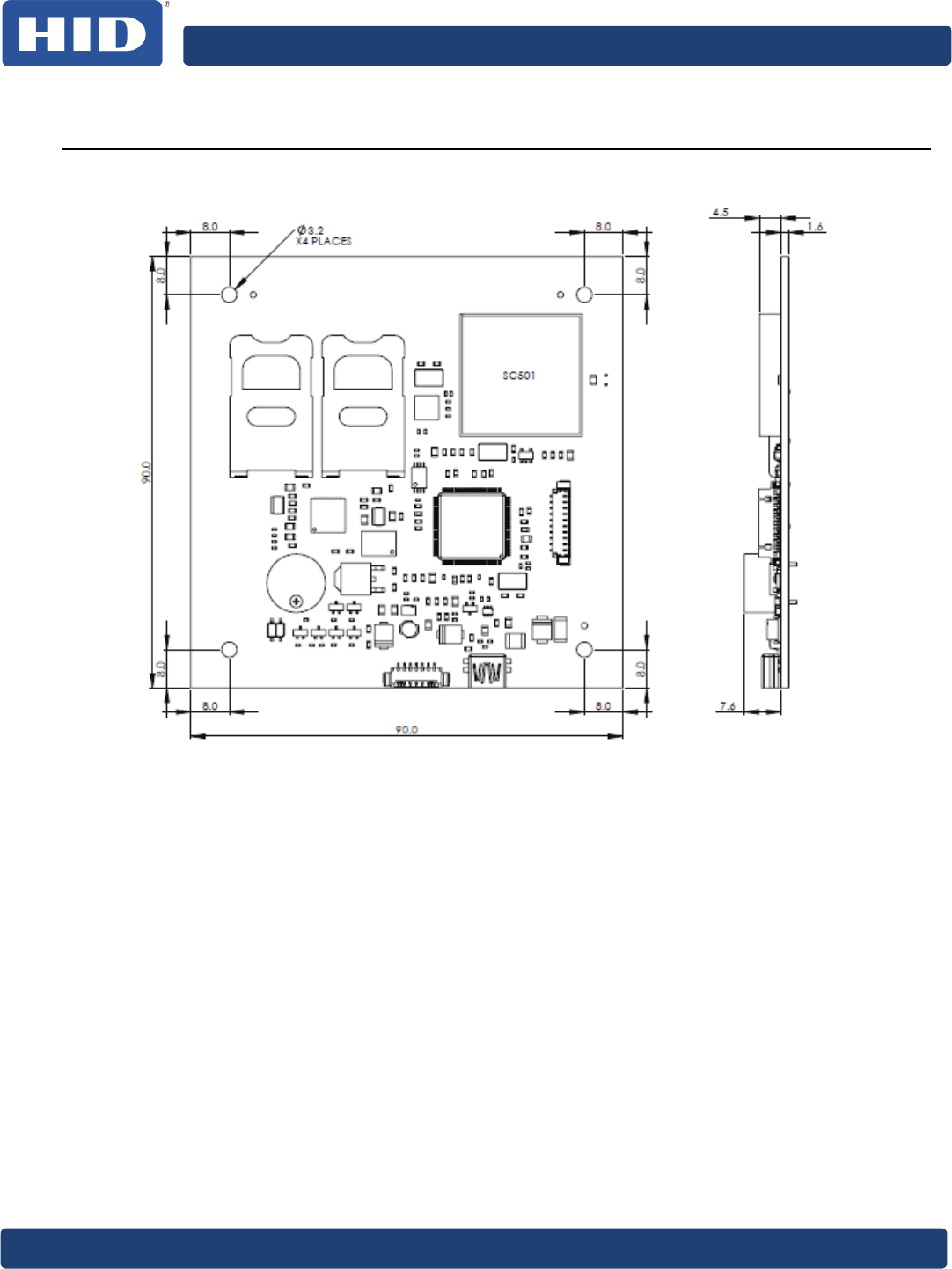
Mechanical Drawings
Figure 8: Mechanical Drawing (Dimensions = mm)
Weight: 38Gramm

hidglobal.com