DETECTION MONITORING TECHNOLOGIES AIMSFS-05X AIMS FAST SCAN RADAR SYSTEM (AIMSFS-05X) User Manual MSM855 Detailed
DETECTION MONITORING TECHNOLOGIES, LLC (dba DMT, LLC) AIMS FAST SCAN RADAR SYSTEM (AIMSFS-05X) MSM855 Detailed
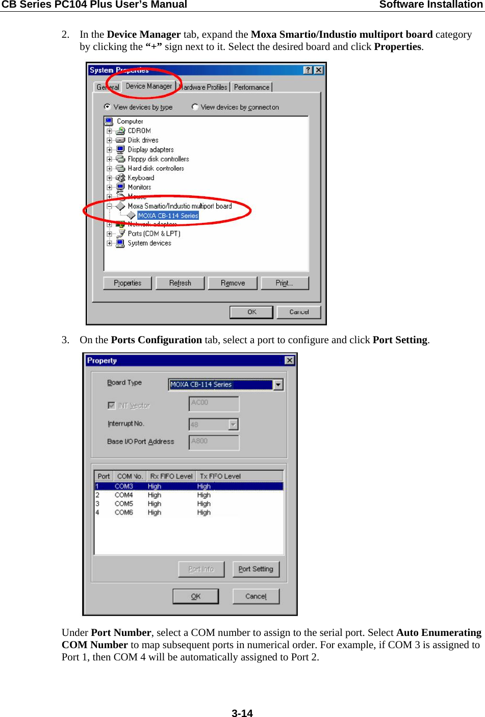
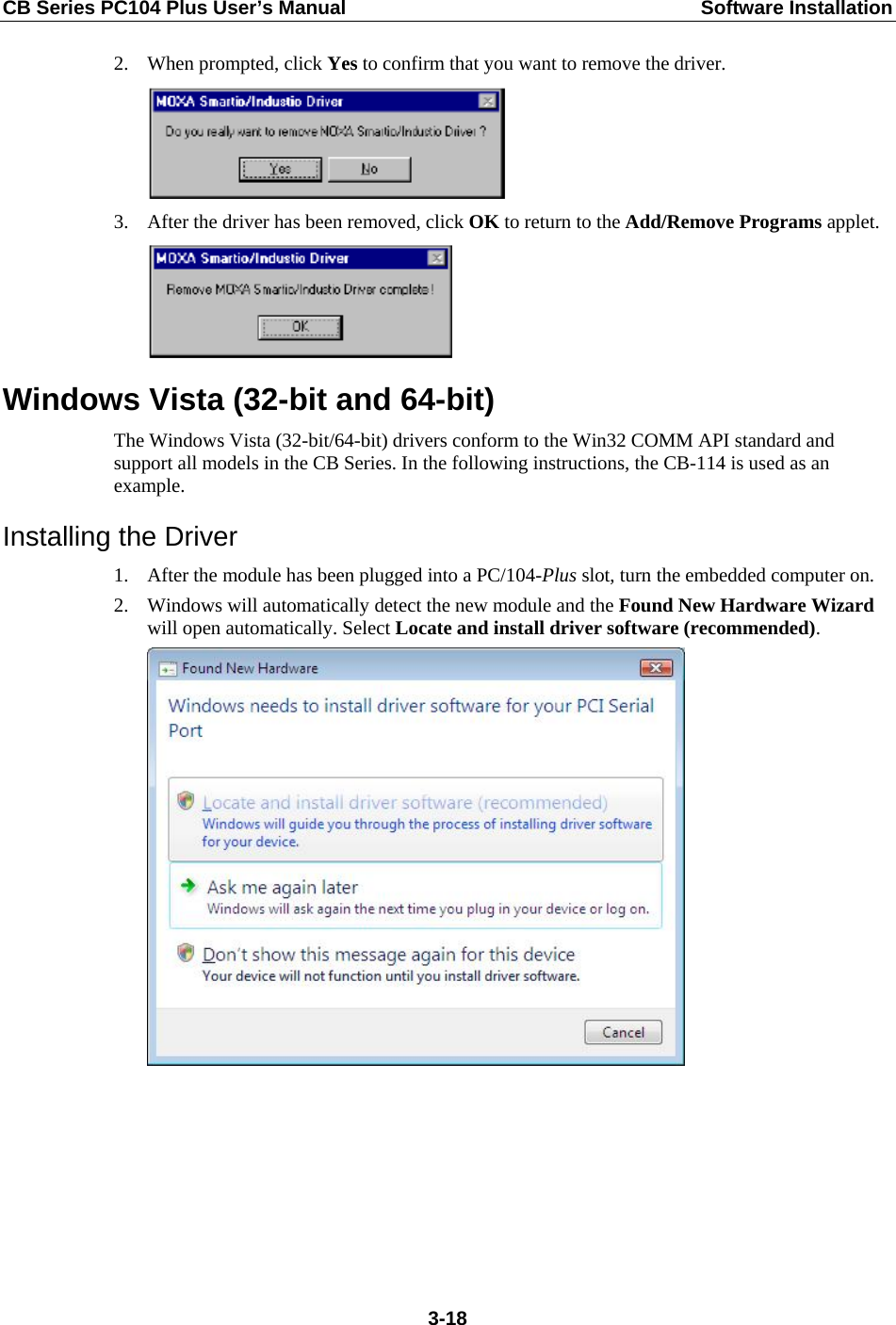
UserManual.wiki
>
DETECTION MONITORING TECHNOLOGIES
>
AIMSFS-05X User Manual
>
User Manual 2
Contents
1.
User Manual 1A
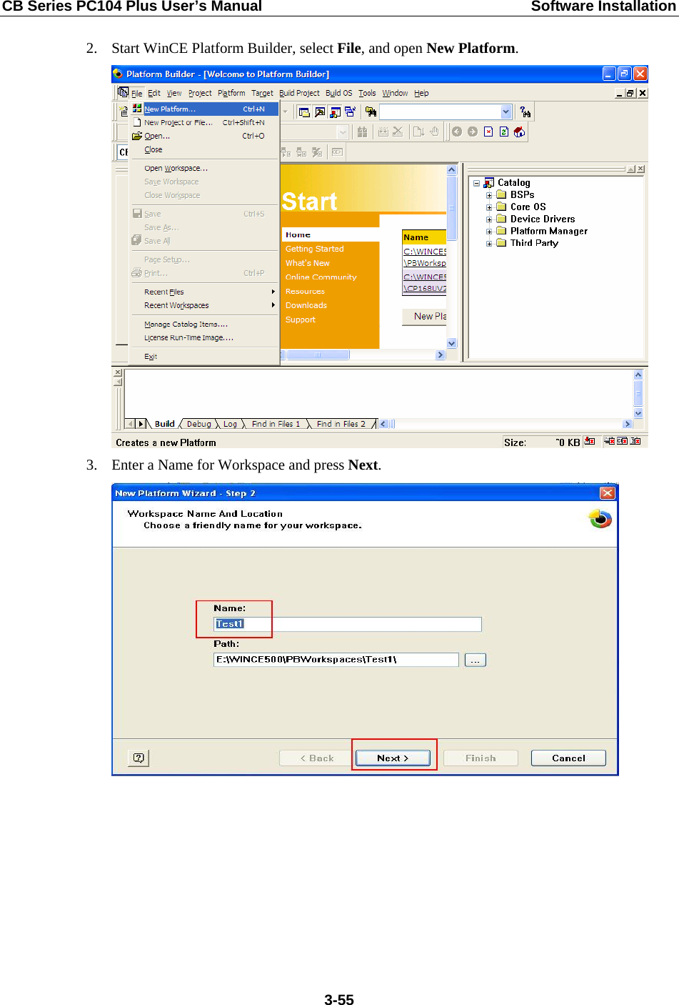
2.
User Manual 1B
3.
User Manual 2
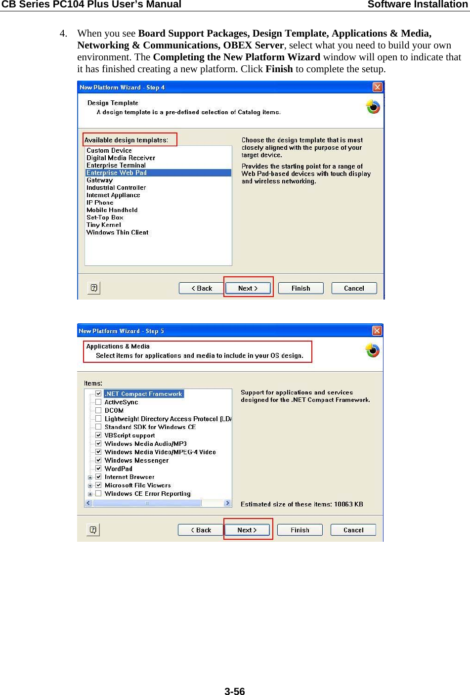
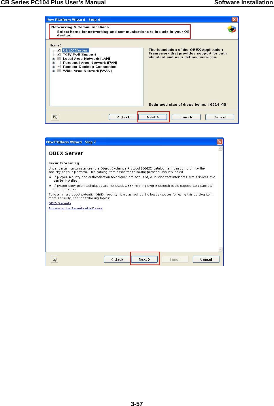
4.
Installation Guide 1
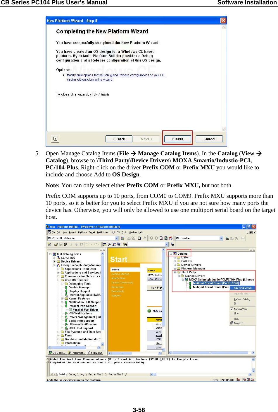
5.
Installation Guide 2
6.
Installation Guide 3
User Manual 2
Navigation menu
Upload a User Manual
Namespaces
Wiki Guide
HTML
PDF
Info
Views
User Manual
Discussion / Help
Navigation
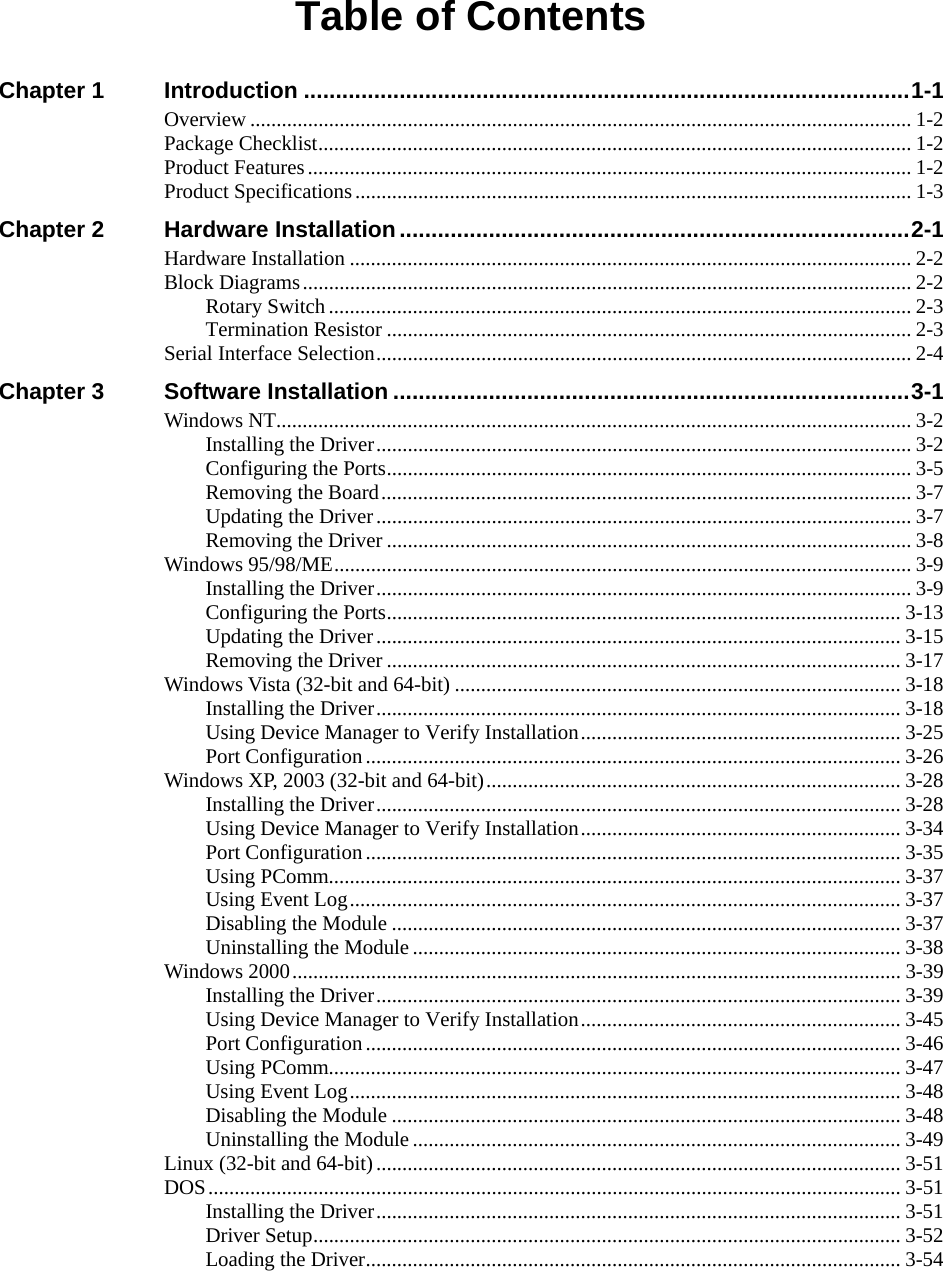
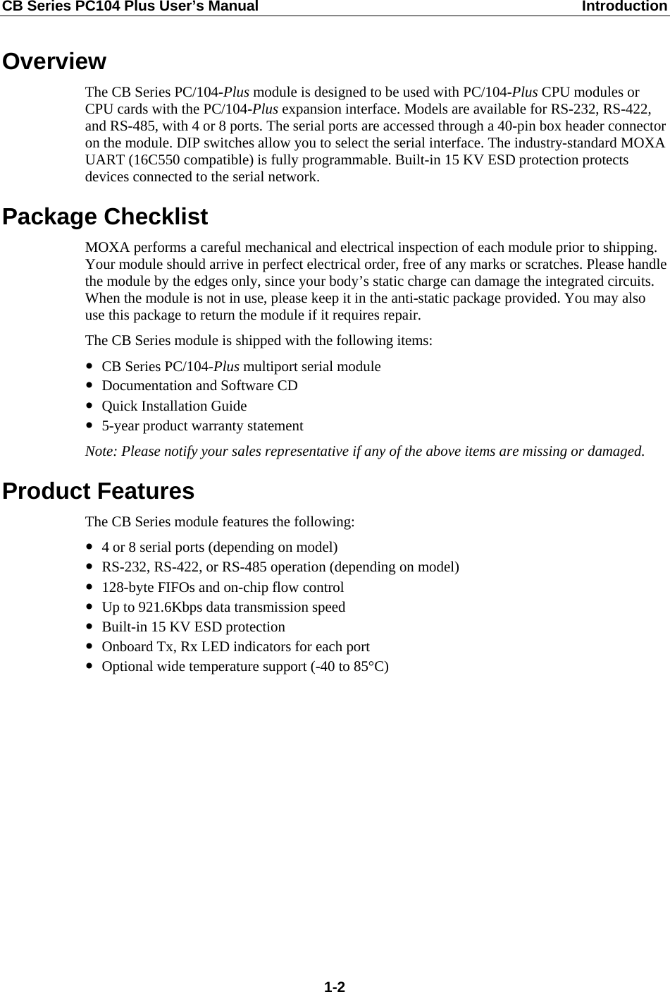
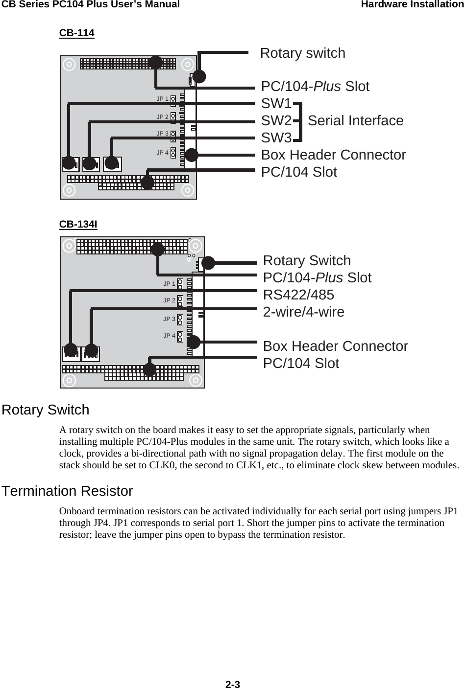
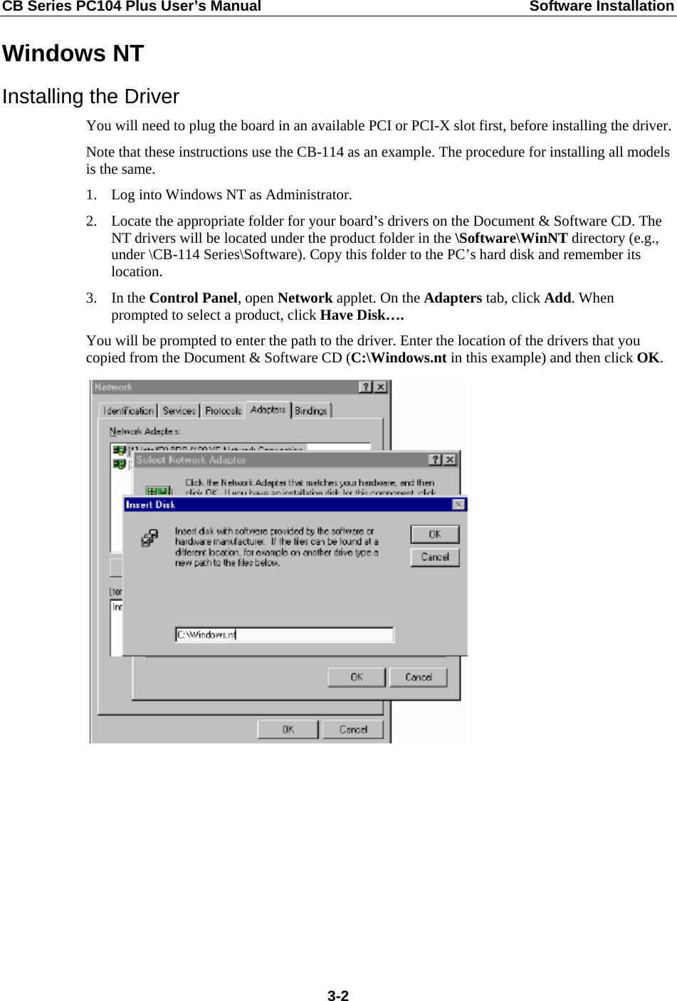
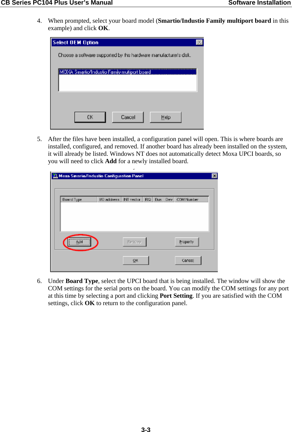
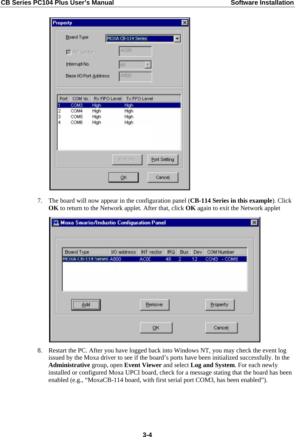
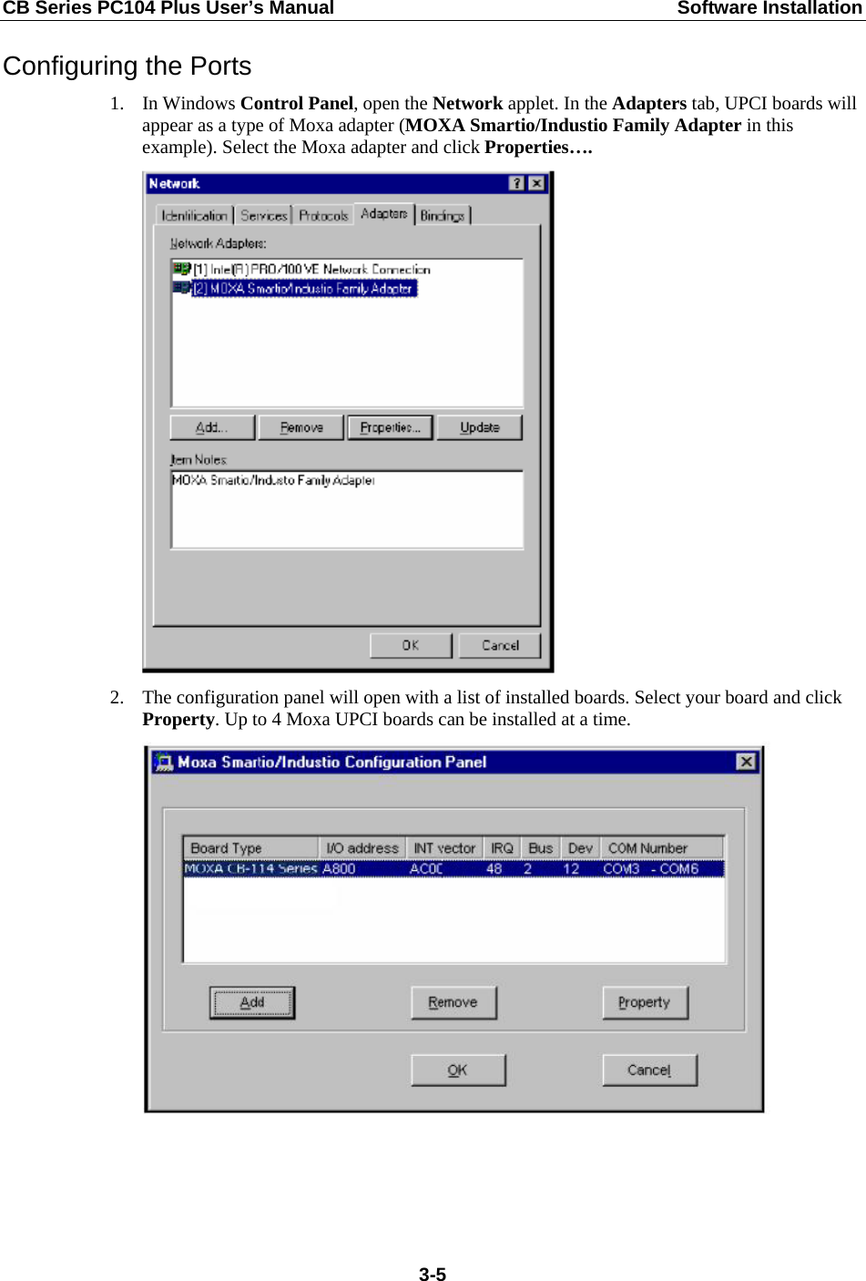
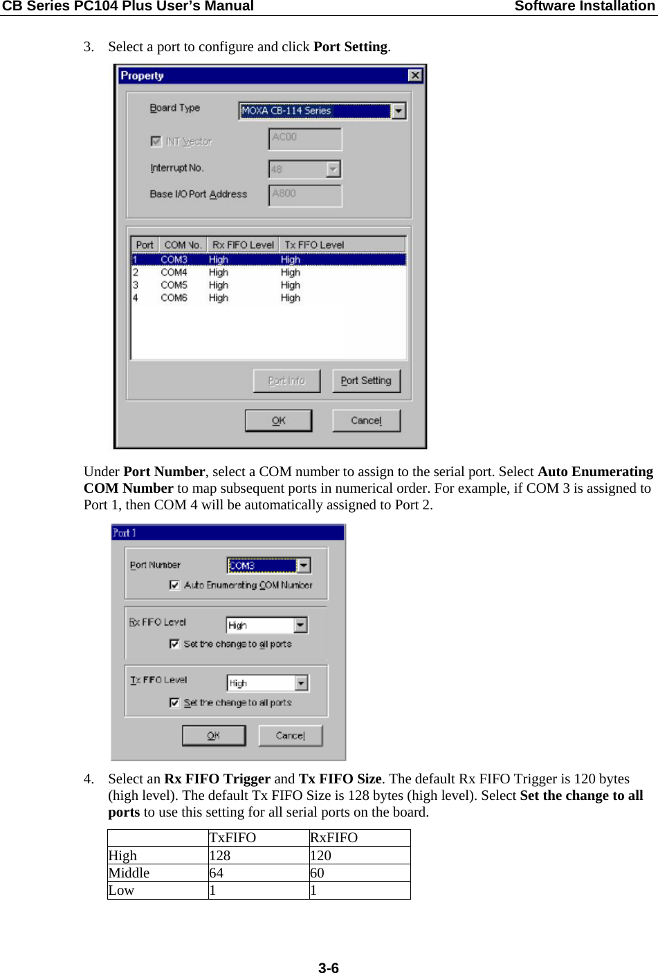
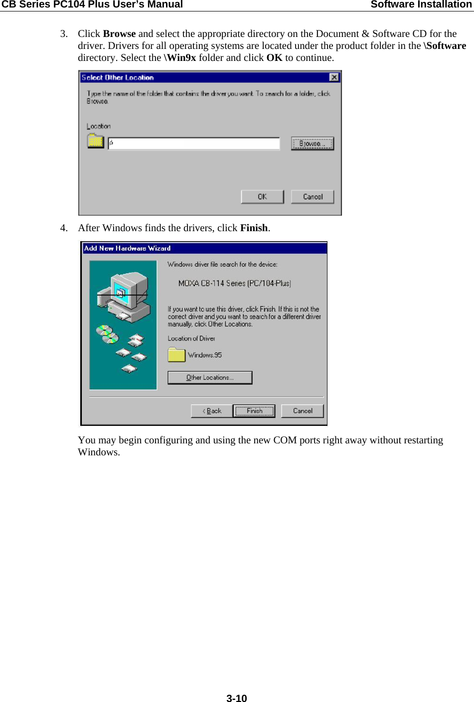
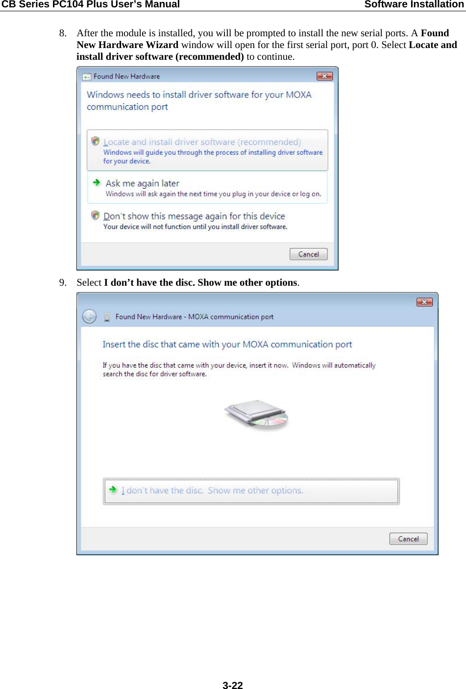
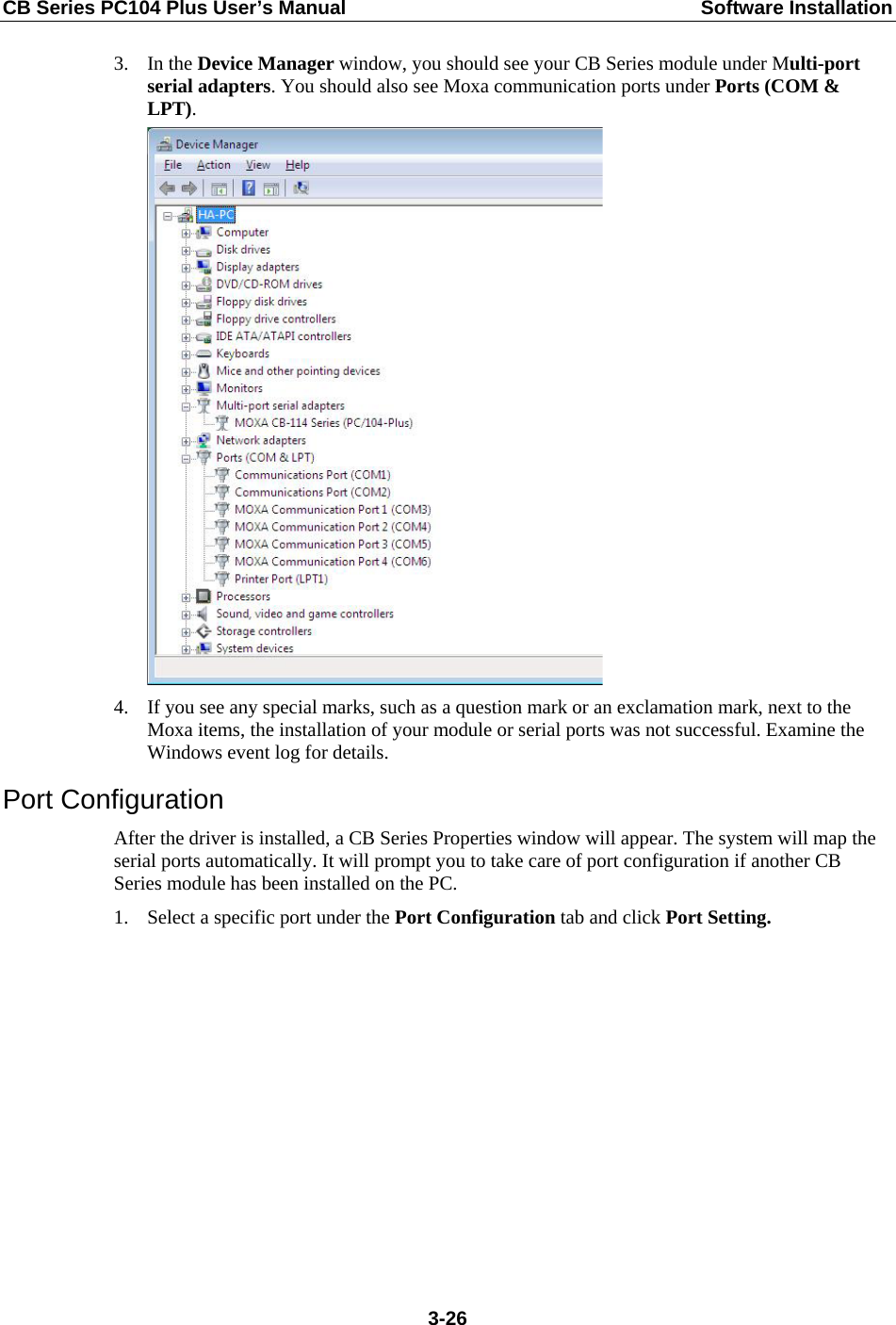
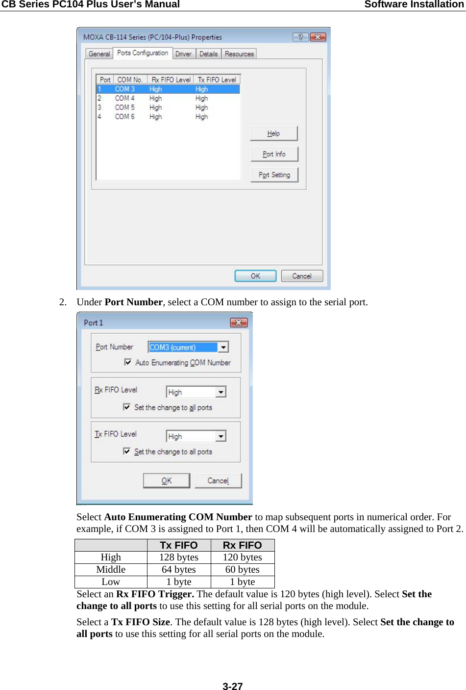
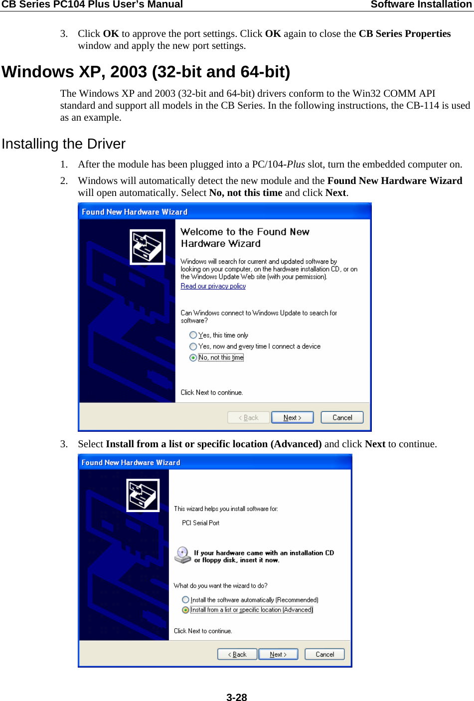
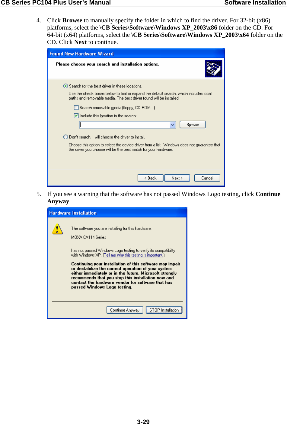
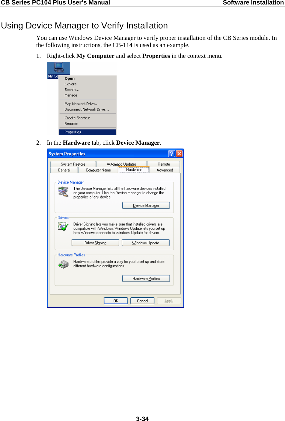
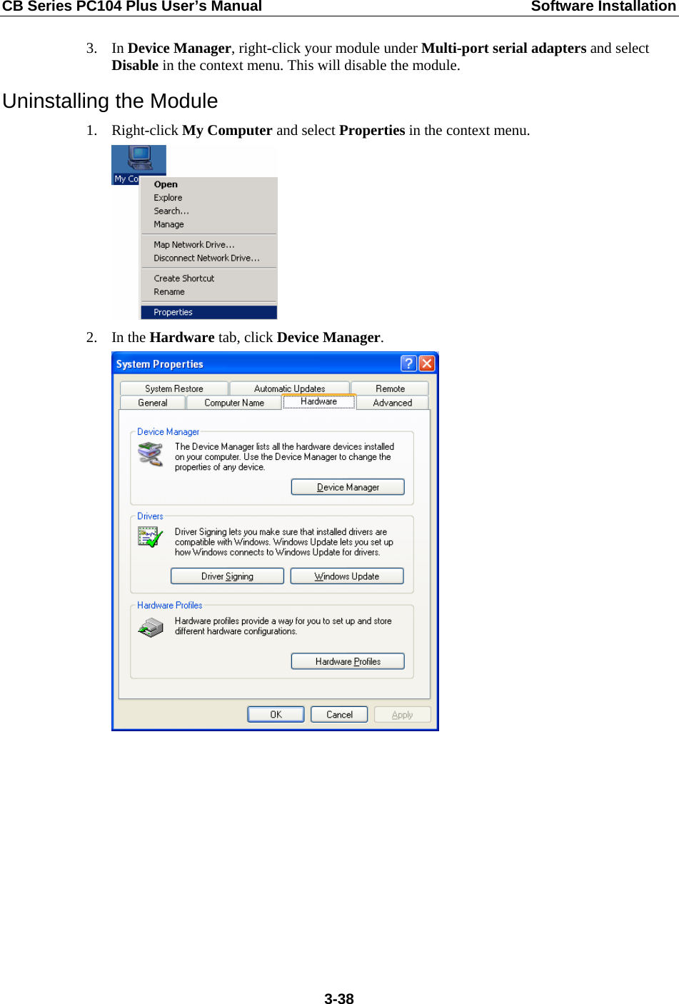
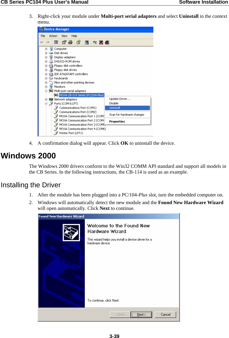
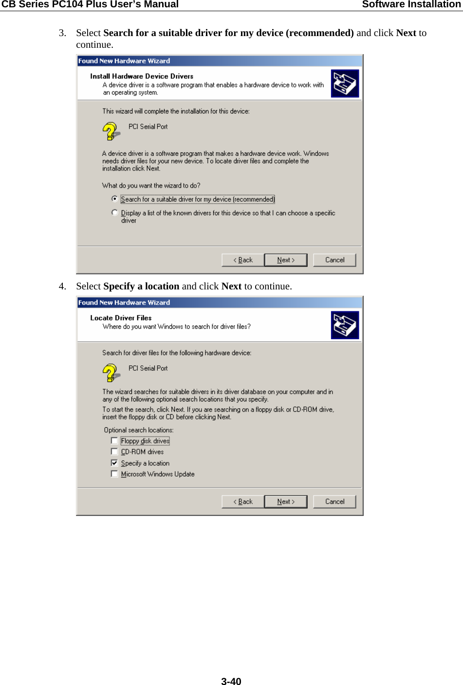
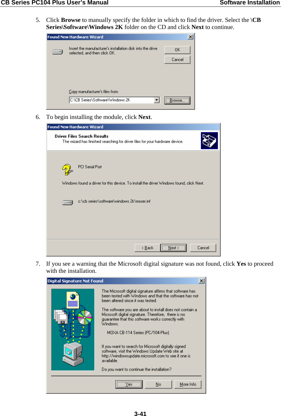
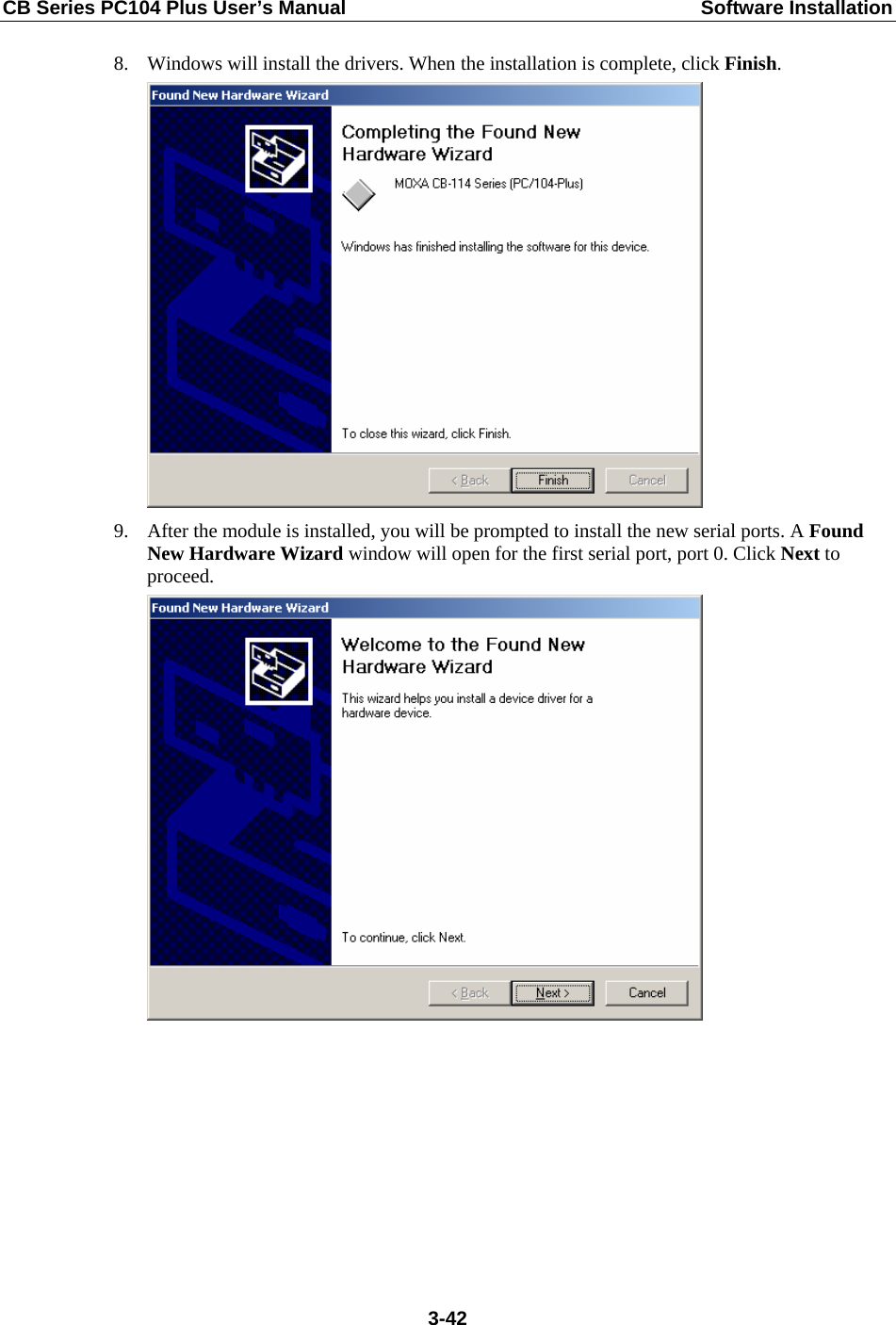
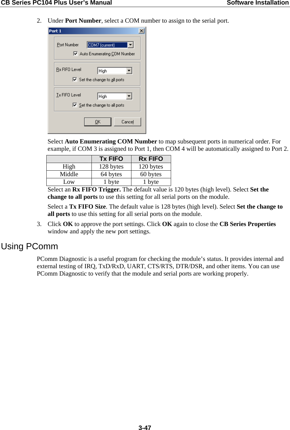
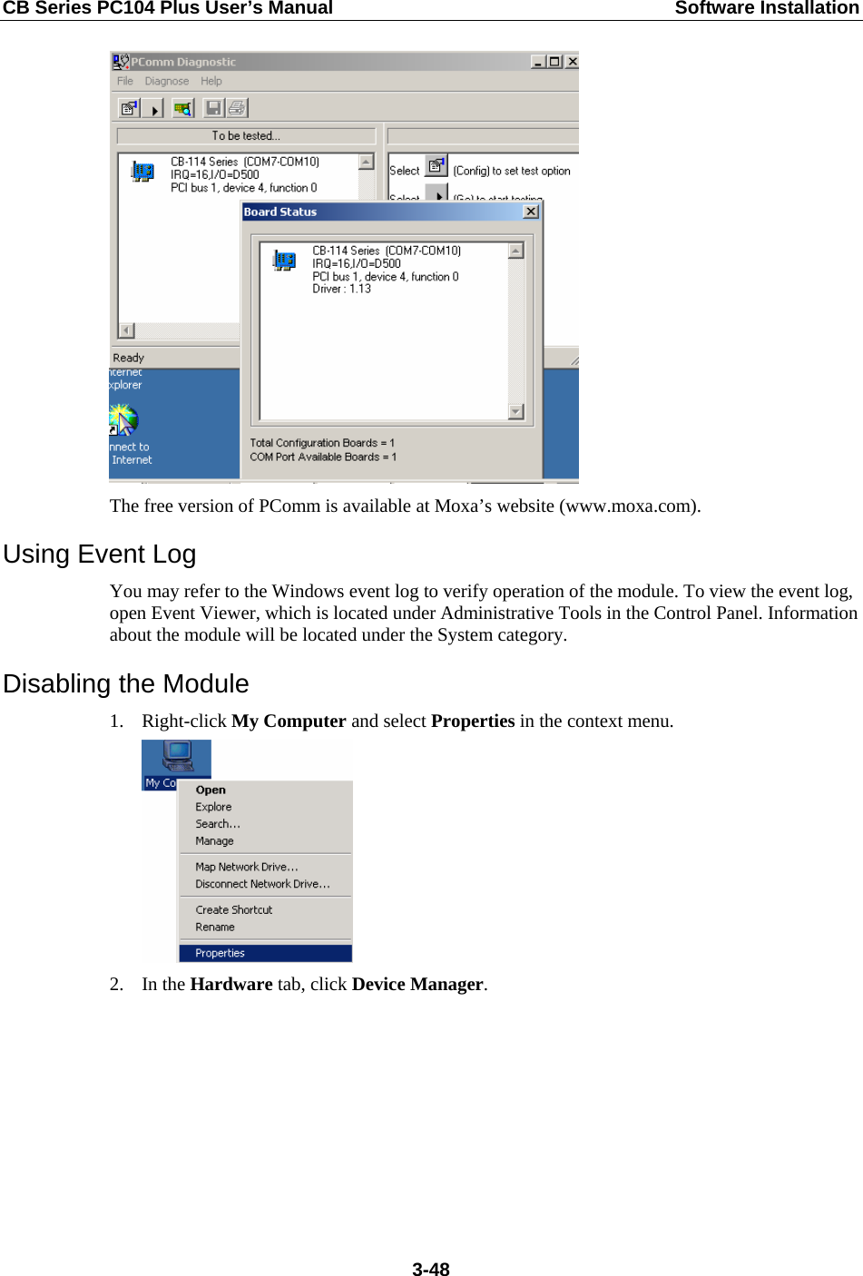
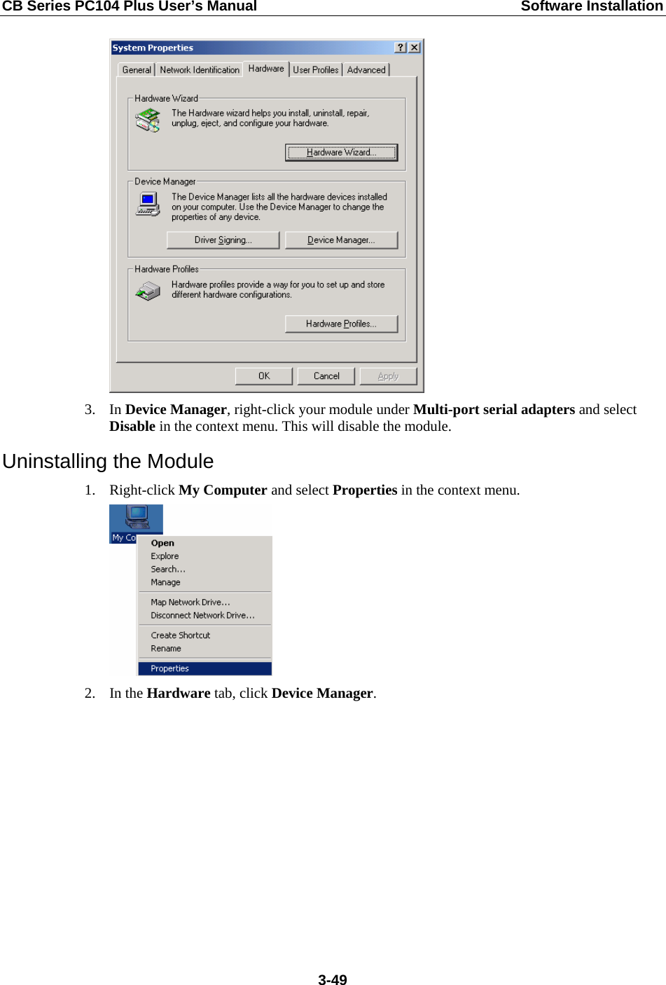
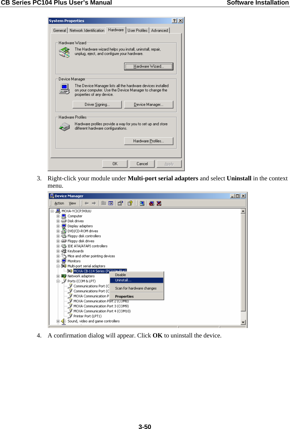
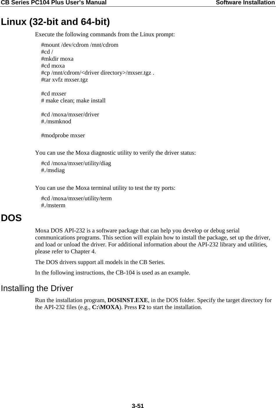
![CB Series PC104 Plus User’s Manual Software Installation 10. Select Search for a suitable driver for my device [recommended] and click Next. 11. Select Specify a location and click Next. 12. Select the \CB Series\Software\Windows 2K folder on the CD and click Next. 3-43](https://usermanual.wiki/DETECTION-MONITORING-TECHNOLOGIES/AIMSFS-05X.User-Manual-2/User-Guide-1532463-Page-54.png)
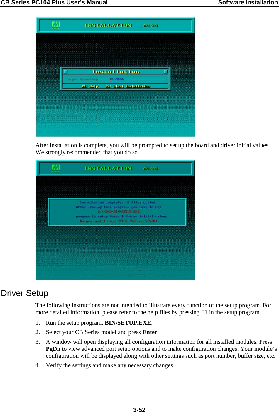
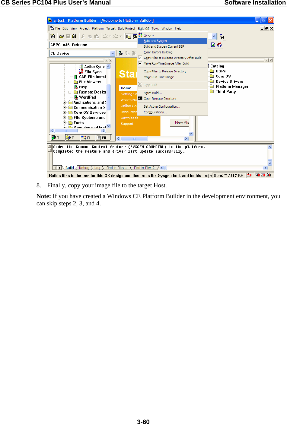
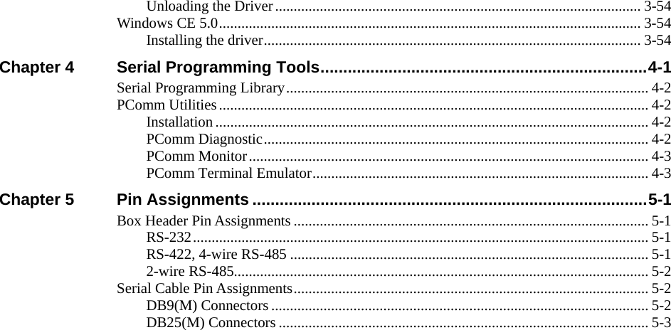
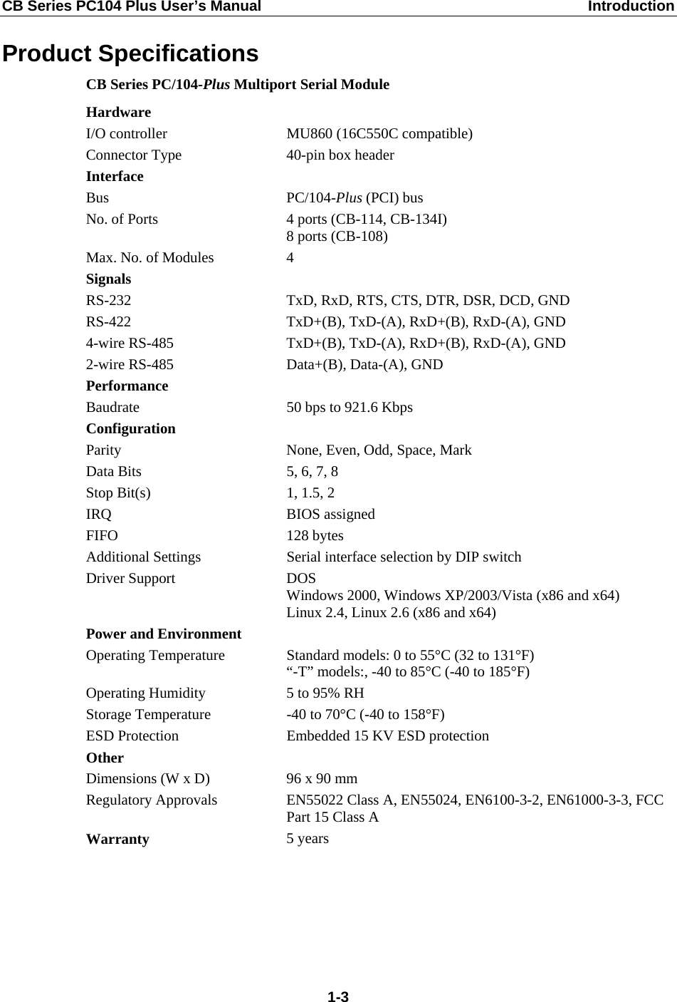
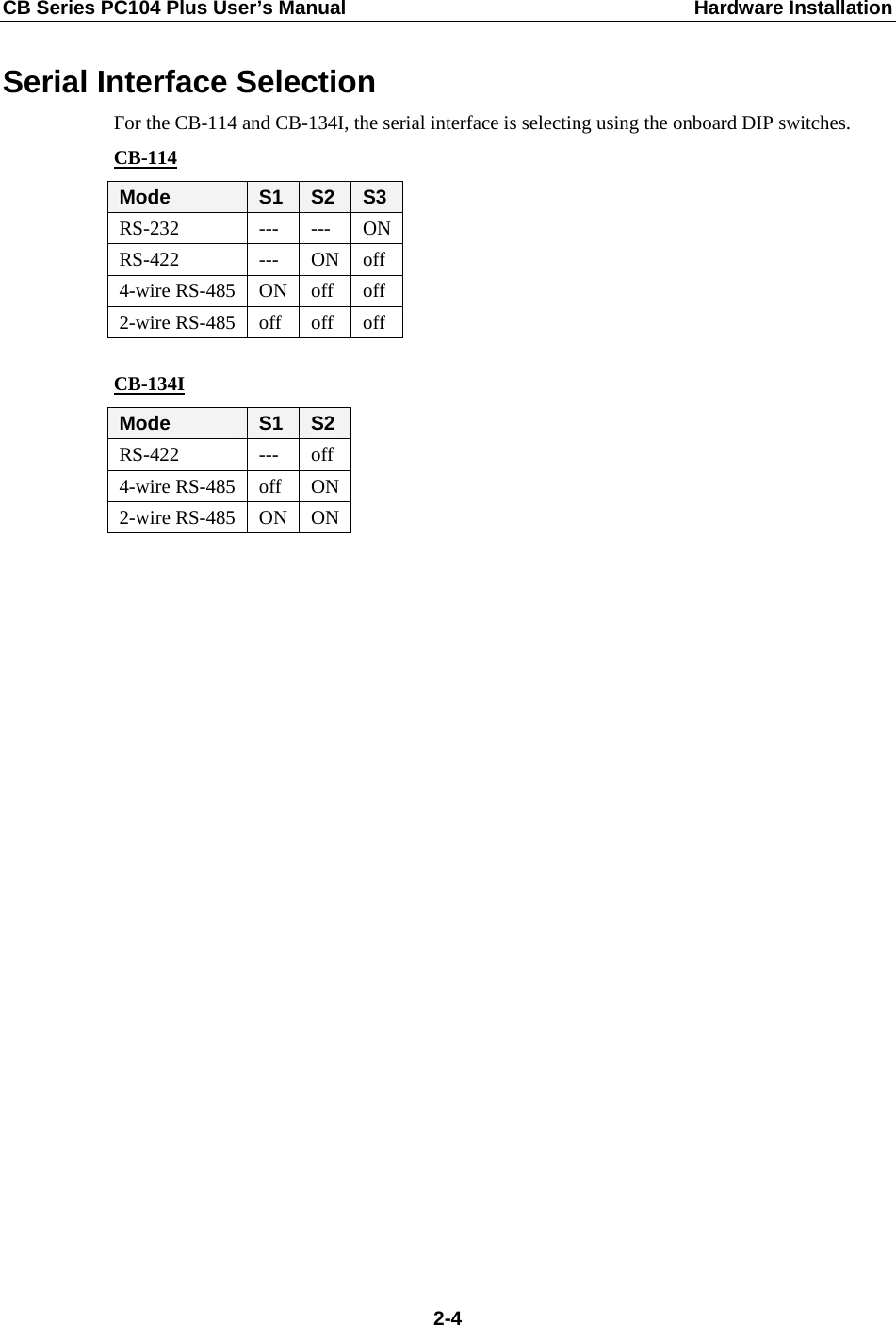
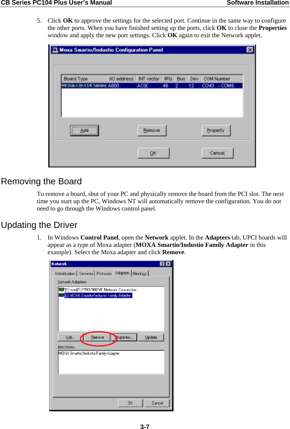
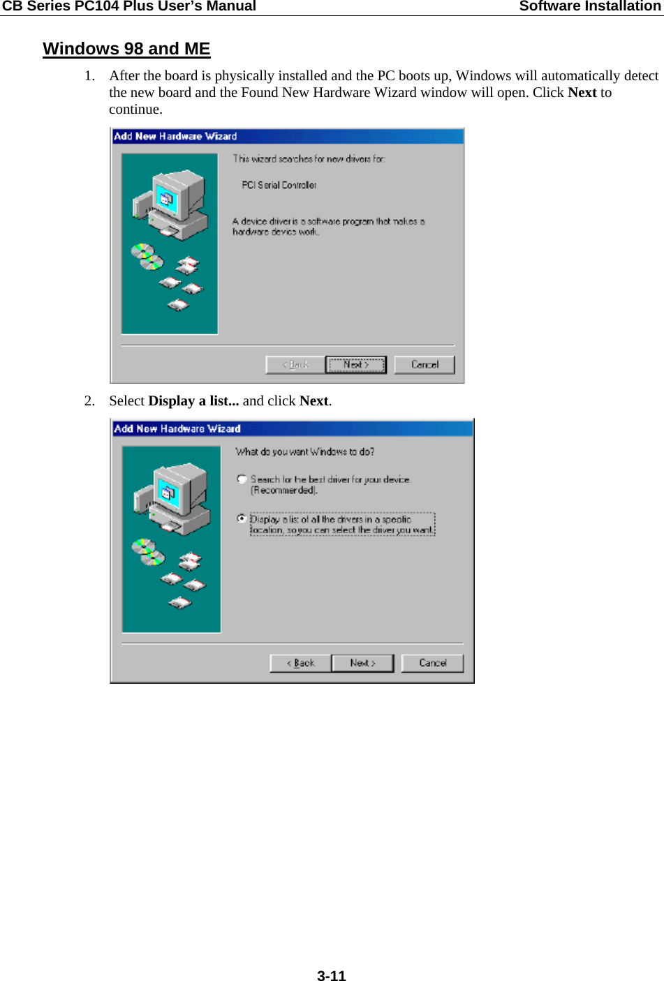
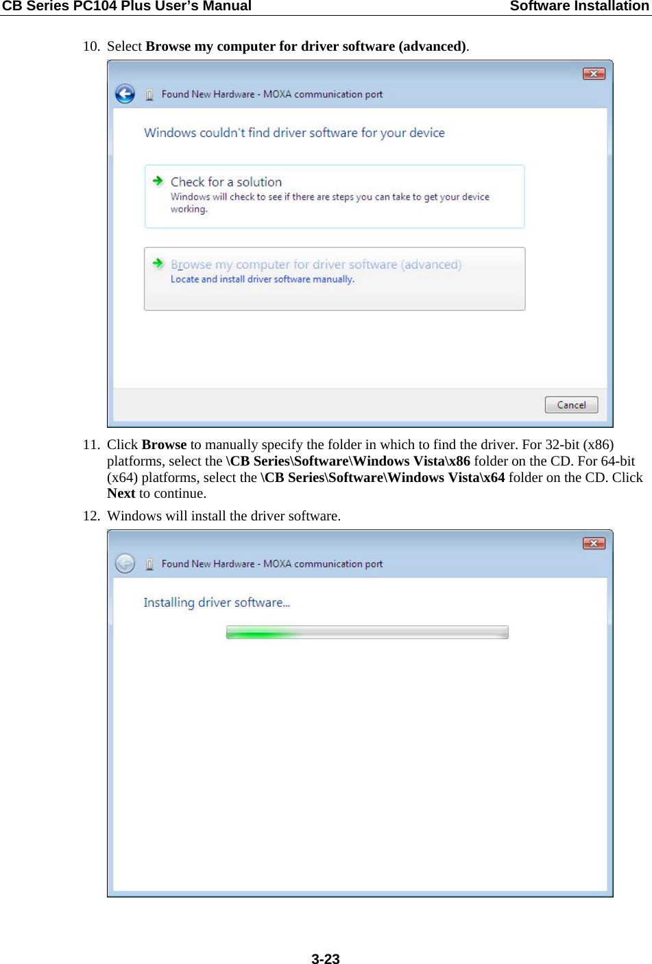
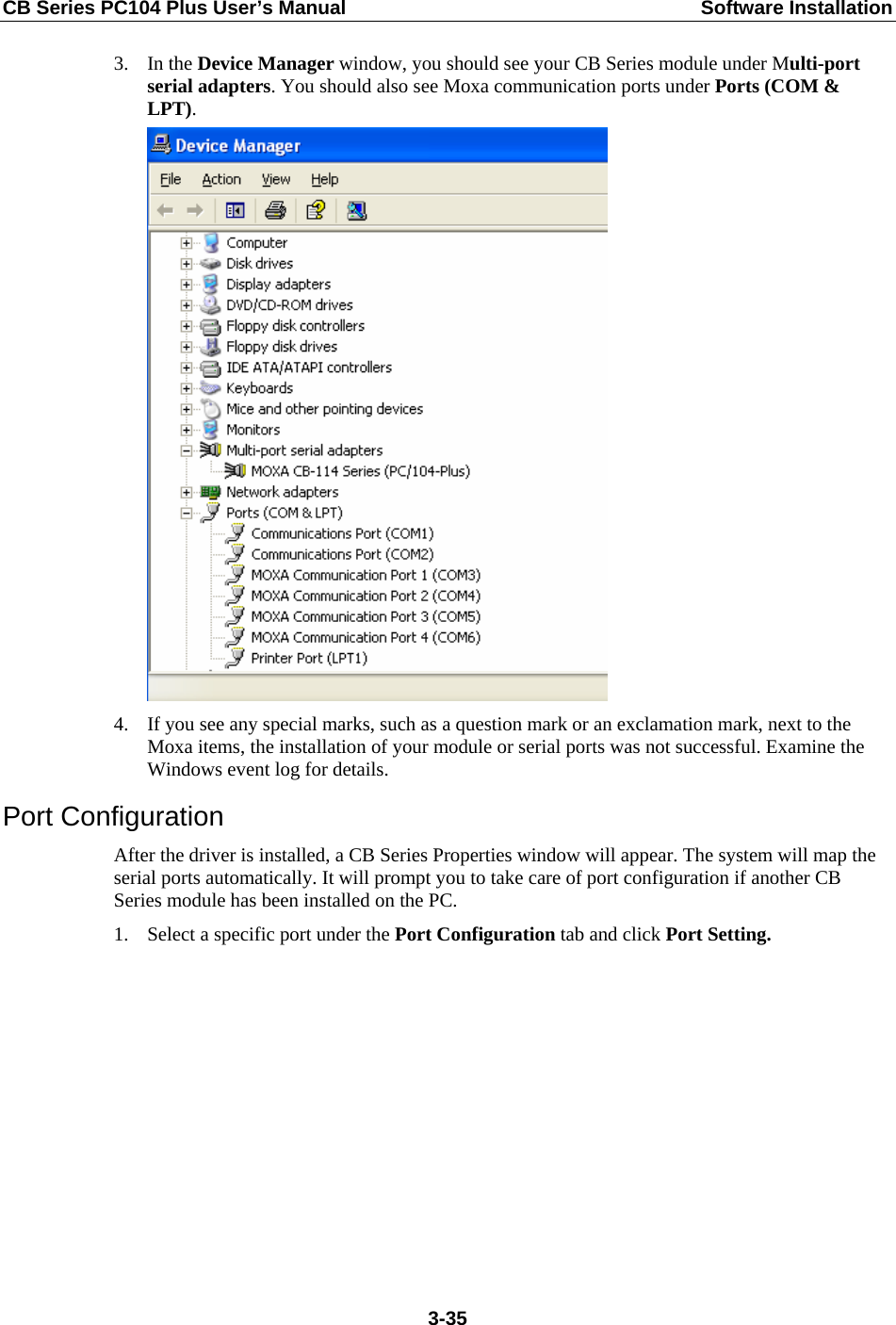
![CB Series PC104 Plus User’s Manual Software Installation 6. After adding Moxa Tech drivers into your OS Design, a new project is automatically added to your workspace. The project name is mxserce5. The project can be accessed from File View (View Æ File View). The mxserce5 project contains a number of files used to configure the drivers included in your OS Design. Note: If you would like to use “Terminal Emulator” tool, please modify mxserce5.reg and keyboard like below (This is only just for “one” “COM” port). You have to notice number of ports, COM, MXU and enter the correct information. [HKEY_LOCAL_MACHINE\ExtModems\HayesCompat1] “Port”=”COM2:” “DeviceType”=dword:1 “FriendlyName”=”Hayes Compatible on COM2:” 7. Finally, open Build OS, select Build and Sysgen, and be sure to click Copy Files to Release Directory After Build and Make Run-Time Image After Build. 3-59](https://usermanual.wiki/DETECTION-MONITORING-TECHNOLOGIES/AIMSFS-05X.User-Manual-2/User-Guide-1532463-Page-70.png)