DIGIRAY CRSCANNER4 RFID Reader User Manual Fire ID EN130708
3D IMAGING & SIMULATIONS CORP. RFID Reader Fire ID EN130708
UserManual.wiki
>
DIGIRAY
>
CRSCANNER4 User Manual
Users Manual
Navigation menu
Upload a User Manual
Namespaces
Wiki Guide
HTML
PDF
Info
Views
User Manual
Discussion / Help
Navigation
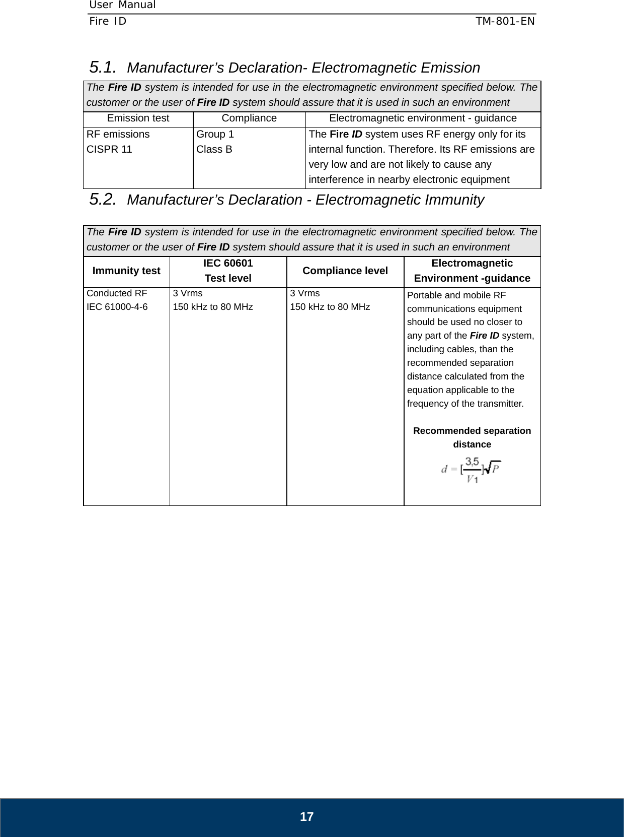
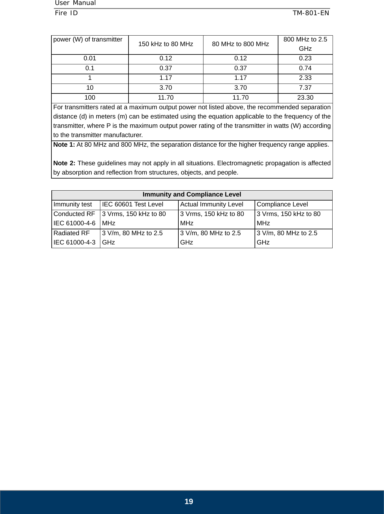
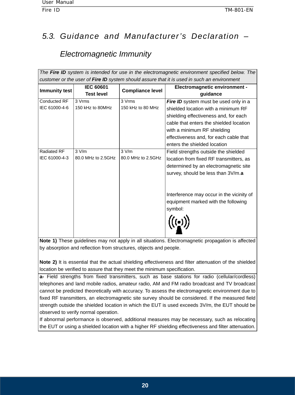
![User Manual Fire ID TM-801-EN 18 Radiated RF IEC 61000-4-3 3 V/m 80.0 MHz to 2.5 GHz 3 V/m 80.0 MHz to 2.5 GHz Recommended separation distance Where P is the maximum output power rating of the transmitter in watts (W) according to the transmitter manufacturer and d is the recommended separation distance in meters (m). Field strengths from fixed RF transmitters, as deter-mined by an electromagnetic site survey,(a) Should be less than the compliance level in each frequency range (b). Interference may occur in the vicinity of equipment marked with the following symbol: Note 1) At 80 MHz and 800 MHz, the higher frequency range applies. Note 2) These guidelines may not apply in all situations. Electromagnetic propagation is affected by absorption and reflection from structures, objects and people. a Field strengths from fixed transmitters, such as base stations for radio (cellular/cordless) telephones and land mobile radios, amateur radio, AM and FM radio broadcast and TV broadcast cannot be predicted theoretically with accuracy. To assess the electromagnetic environment due to fixed RF transmitters, an electromagnetic site survey should be considered. If the measured field strength in the location in which the EUT is used exceeds the applicable RF compliance level above, the EUT should be observed to verifynormal operation. If abnormal performance is observed, additional measures may be necessary, such as re-orienting or relocating the EUT. b Over the frequency range 150 kHz to 80 MHz, field strengths should be less than [V1] V / m. Recommended Separation Distances Between Portable and Mobile RF Communications Equipment and the Fire ID system. The Fire ID system is intended for use in an electromagnetic environment in which radiated RF disturbances are controlled. The user of the Fire ID system can help prevent electromagnetic interference by maintaining a minimum distance between portable and mobile RF communications equipment (transmitters) and the Fire ID system as recommended below, according to the maximum output power of the communications equipment. Rated maximum output Separation distance (m) according to frequency of transmitter](https://usermanual.wiki/DIGIRAY/CRSCANNER4/User-Guide-2090625-Page-18.png)