DIGIRAY CRSCANNER4 RFID Reader User Manual Fire ID EN130708
3D IMAGING & SIMULATIONS CORP. RFID Reader Fire ID EN130708
DIGIRAY >
Users Manual

ID
User Manual
Doc No. : TM- 501 EN
Rev 0.1.8 July. 2013
Part No. : CR-FPM-54-001
3DISC, Fire ID, Quantor and the 3D Cube are trademarks of 3D Imaging & Simulations Corp,
South Korea, and its affiliates. All other trademarks are held by their respective owners and
are used in an editorial fashion with no intention of infringement. The data in this publication
are for illustration purposes only and do not necessarily represent standards or specifications,
which must be met by 3D Imaging & Simulations Corp. All information contained herein is
intended for guidance purposes only, and characteristics of the products and services described
in this publication can be changed at any time without notice. Products and services may not
be available in your local area. Please contact your local sales representative for availability
information. 3D Imaging & Simulations Corp. strives to provide as accurate information as
possible, but shall not be responsible for any typographical error.
© Copyright 2010 3D Imaging & Simulations Corp, all rights reserved, printed, and published
in South Korea by 3D Imaging & Simulations Corp.
User Manual
Fire ID TM-801-EN
2
3DISC Americas
22560 Glenn Dr, Suite 116
Sterling, VA 20164 USA
Tel : 1-703-430-6080
E-mail : info@3DISCimaging.com
Contact
815, Tamnip-Dong, Yuseong-Gu,
Daejeon, Korea
Tel : 82-42-931-2100
Fax : 82-42-931-2299
Website : www.3DISCimaging.com
E-mail : info@3DISCimaging.com
3DISC Europe
Gydevang, 39-41, 3450 Alleroed, Denmark
Tel : 45-88-276-650
E-mail : info@3DISCimaging.com

User Manual
Fire ID TM-801-EN
3
The device complies with Part 15 of the FCC Rules. Operation is subject to the condition
that this device does not cause harmful interference.
NOTE : This equipment has been tested and found to comply with the limits for a Class B Digital
Device, pursuant to Part 15 of the FCC Rules. These limits are designed to provide reasonable
protection against harmful interference in a residential installation. This equipment generates,
uses and can radiate radio frequency energy and, if not installed and used in accordance with
the instruction, may cause harmful interference to radio communication. However, there is no
guarantee that interference will not occur in a particular installation. If this equipment dose
cause harmful interference to radio or television reception, which can be determined by turning
the equipment off and on, the user is encouraged to try to correct the interference by one or
more of the following measures : - Reorient or relocate the receiving antenna. - Increase the
separation between the equipment and receiver - Connect the equipment into an outlet on a
circuit different from that to which the receiver is connected. - Consult the dealer or an
experienced radio/TV technician for help.
User Manual
Fire ID TM-801-EN
4
Warnings and Used Symbols
To ensure the safety of patients, staff and other persons, any changes to software and hardware
delivered by 3D Imaging & Simulations Corp. may only be made with prior written permission
from 3D Imaging & Simulations Corp.
The following symbols will be used throughout this manual:
DANGER
The functionality of the system can be destroyed in the case of
incorrect use.
If unauthorized changes have been made to delivered system and
accessories, the warranty by 3D Imaging & Simulations Corp.
becomes void. 3D Imaging & Simulations Corp. will not accept
any responsibility or liability for the improper functioning of the
product in such a case.
WARNING
The functionality of the system can be limited in the case of
incorrect use. Hints that require special attention.
NOTE
Notes represent information that is important to know but which do
not affect the functionality of the system.
DANGER
This equipment is indoor use only and all the communication
wirings are limited to inside of the building.

User Manual
Fire ID TM-801-EN
5
General Safety Guidelines
This device has been designed and tested to meet strict safety requirements applicable to IT
equipment, and has been supplied in a safe condition. 3D Imaging & Simulations Corp.
assumes no liability for failure to comply.
If this device is not used as specified, the protection provided by the device could be impaired.
This device must be used in a normal condition only.
There are no user serviceable parts inside this device. The device should only be opened and
serviced by qualified service personnel. If there is a service problem, please contact 3D
Imaging & Simulations Corp. or authorized dealer.
Do not spill liquids on the device, and never operate the device in a wet environment.
Keep the device from radiators and heat sources.
Use the device only with accessories supplied with this device.
This device contains static sensitive components. Proper static handling procedures and
equipment must be used when servicing this device.
If any of the following conditions occur, unplug the device from the PC to USB cable and contact
authorized service personnel.
z The USB cable is damaged.
z An object has fallen into the device.
z The device has been exposed to water.
z The device has been dropped or damaged.
z The device does not operate correctly when the operating instructions are followed.
z

User Manual
Fire ID TM-801-EN
6
Index of contents
Chapter 1. Introduction ..................................................................... 8
Chapter 2. Unpacking ....................................................................... 9
2.1. Inspection for Damage ..................................................................... 9
2.2. Identify the Components ................................................................... 9
Chapter 3. Setting Up ..................................................................... 10
3.1. Identify Important Features ............................................................. 10
3.1.1. Reader Connecting Part ........................................................... 10
3.2. Computer Requirements ............................................................... 111
3.2.1. Recommended Requirement ................................................... 111
3.2.2. Minimum Requirement .............................................................. 11
3.3. Connect the USB Cable .................................................................. 11
3.3.1. Connect USB Interface Cable .................................................... 11
3.3.2. Installation Report ................................................................... 121
Chapter 4. Operating .................................................................... 133
4.1. System Specifications .................................................................. 133
4.2. Operating Instructions .....
오류
!
책갈피가
정의되어
있지
않습니다
.4
4.2.1. Circuit Functions ....................................................................... 14
Chapter 5. Symbols ........................................................................ 15
5.1. Manufacturer’s Declaration ............................................................ 17
5.1. - Electromagnetic Emission ........................................................... 17
5.2. Manufacturer’s Declaration - Electromagnetic Immunity ................ 17
5.3. Guidance and Manufacturer’s Declaration – Electromagnetic
Immunity ..................................................................................................... 20
Chapter 6. Warranty and Repair Service ........................................ 21
6.1. Standard Warranty.......................................................................... 21
6.2. Repair Service ................................................................................ 21
6.3. Out of Warranty Repair Service ...................................................... 21
6.4. Shipping ......................................................................................... 22

User Manual
Fire ID TM-801-EN
7
Chapter 7. Technical Assistance ..................................................... 23

User Manual
Fire ID TM-801-EN
8
Chapter 1. Introduction
Compact & Affordable
The Fire ID is compact and affordable, helping to increase patient throughput and improve the
overall productivity of your practice. With its small footprint, the reader fits seamlessly into even
the most space-challenged clinic and exam rooms.
Elegant Design & Streamlined Operation
The Fire ID’s elegant design belies a powerful yet easy-to-use system that gets the job done
day in and day out.
User Manual
Fire ID TM-801-EN
9
Chapter 2. Unpacking
2.1. Inspection for Damage
Fire ID is shipped in a custom designed box to protect the reader from external shock. Before
unpacking the reader, inspect the shipping box for damage. In case the box is damaged, notify
the shipper immediately.
2.2. Identify the Components
Open the shipping container and identify each of these components.
Part No. Item
CR-FP-51-001 Fire ID
CR-FPA-02-004 USB Mini 5pin cable
WARNING
Improper disposal of this product may result in environmental
contamination. When disposing of this equipment, contact 3D
Imaging & Simulations Corp.’s representative or related organs
of government. Do not dispose of any part of this equipment
without consulting a 3D Imaging & Simulations Corp.’s
representative first.
3D Imaging & Simulations Corp. does not assume any
responsibility for damage resulting from disposal of this equipment
without consulting 3D imaging & Simulations Corp.
WARNING
Use the device passed IEC60950-1 or IEC60601-1 for the product
connected via USB port.
WARNING
If the Fire ID needs to be returned to manufacturer or one of its
representatives, the reader must be repacked in the original box
with all accessories.
User Manual
Fire ID TM-801-EN
10
Chapter 3. Setting Up
3.1 Identify Important Features
Look over the Fire ID and features shown in this section. User will need to know where these
features are when user operates the reader in later chapters.
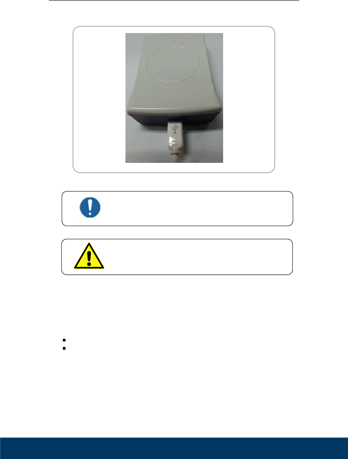
3.1.1. Reader Connecting Part
Figure 2. Reader Connecting Part
WARNING
Unsuitable Installation Sites
Locations with excessive humidity or dust
Locations subject to high temperature
Locations subject to shaking or vibration
Locations exposed to considerable electrical or magnetic
noise, or other forms of electromagnetic energy
Locations with poor heat radiation
USB Mini port

User Manual
Fire ID TM-801-EN
11
3.2. Computer Requirements
3.2.1. Recommended Requirement
Operation System Microsoft Windows 7 (32 bit or 64 bit)
CPU Core Duo / Core2 Processor
Memory RAM 4GB or more
Hard Disk 300GB Free Hard Disk Space
Network 1Gbps Ethernet
Video 32 bit Color Display
Video Resolution 1280 x 1024
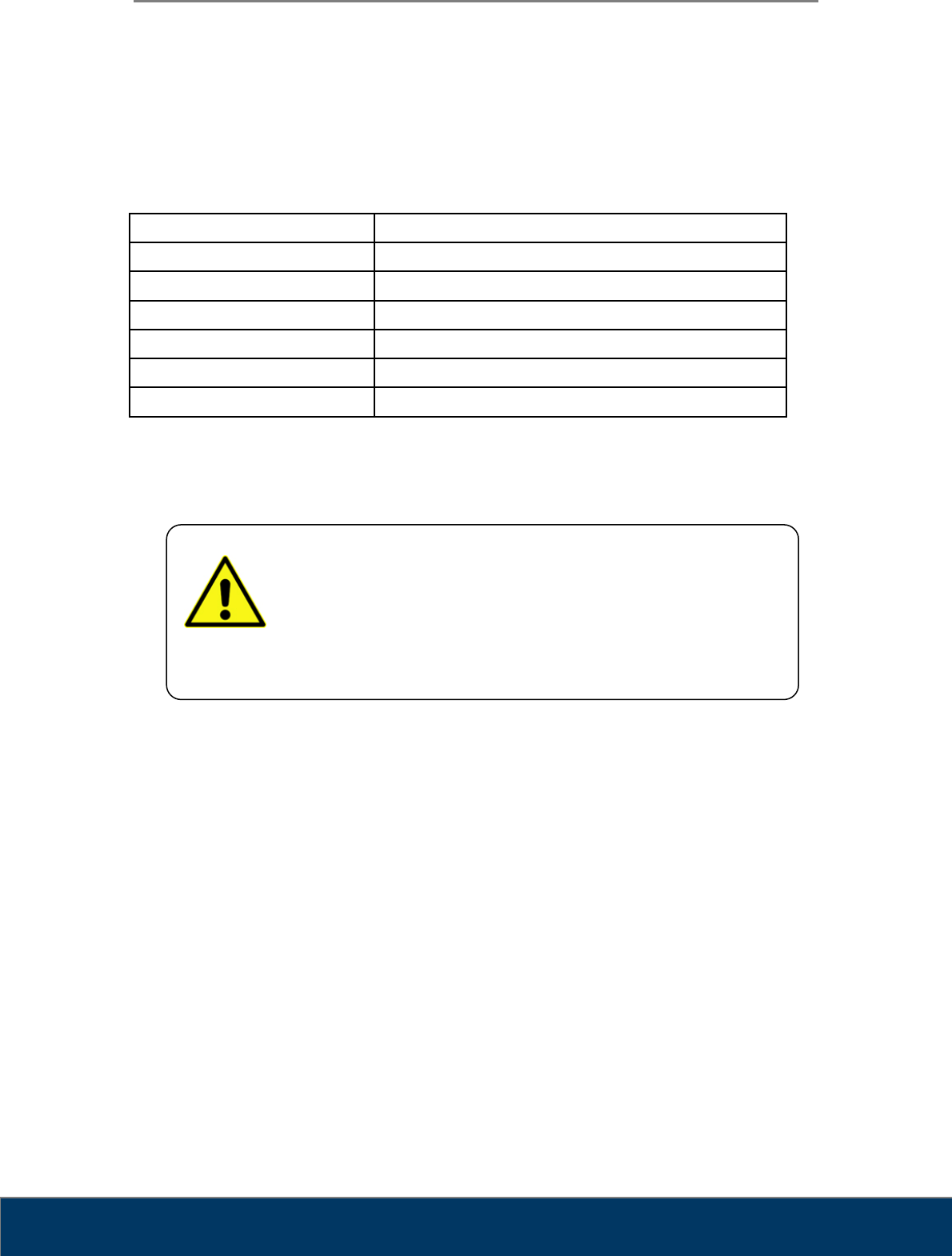
3.2.2. Minimum Requirement
Operation System Microsoft Windows 7 (32 bit or 64 bit)
CPU Core Duo / Core2 Processor
Memory RAM 2GB or more
Hard Disk 80GB Free Hard Disk Space
Network 1Gbps Ethernet
Video 32 bit Color Display
Video Resolution 1280 x 900
3.3. Connect the USB Cable
3.3.1. Connect USB Interface Cable
The reader interfaces with computer via USB Mini 5pin cable.
1. Use the USB cable inside the shipping container.
2. Connect the cable to the reader’s USB Mini port, located on the rear of the reader.
3. Connect the other end of the cable to the USB Mini port on the computer.
User Manual
Fire ID TM-801-EN
12
Figure 4. USB Connection
3.3.2. Installation Report
After installation of the reader, fill in Installation Report from (Appendix I) and send to 3D
Imaging & Simulations Corp. service department by fax or e-mail.
Fax : +82-42-931-2299
E-mail : support@3DISCimaging.com
DANGER
This equipment is indoor use only and all the communication
wirings are limited to inside of the building.
WARNING
Do not pull out the USB cable during tag information reading.
User Manual
Fire ID TM-801-EN
13
Chapter 4. Operating
4.1. System Specifications
Dimension 27 x 60 x 96 (H x L x W)
Weight 90g
Frequency 13.56MHz
Protocol ISO 15693
Interface Mini USB B
Power Supply USB Power
Temperature Range -25℃ to +70℃
* Specifications subject to change without notice.
WARNING
There are no user serviceable parts inside the reader. The
reader should only be opened and serviced by qualified service
personnel. If there is a service problem, please contact 3D
Imaging & Simulations Corp. or authorized dealer.
User Manual
Fire ID TM-801-EN
14
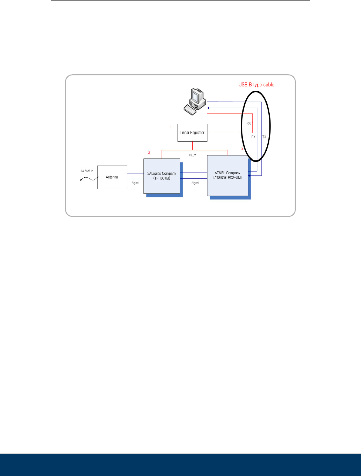
4.2. Operating Specifications
4.2.1. Circuit Functions
Figure 8. Circuit Diagram
9 Linear Regulator:
PC receives power from +3.3V to +5V conversion
9 MCU:
Atmel’s AT89C51ED2-UM
Tag information to the PC via RS-232 communication
Reader chip control
9 Reader chip:
3ALogics’s TRH031M
Intermediate role between the antenna and MCU
User Manual
Fire ID TM-801-EN
15
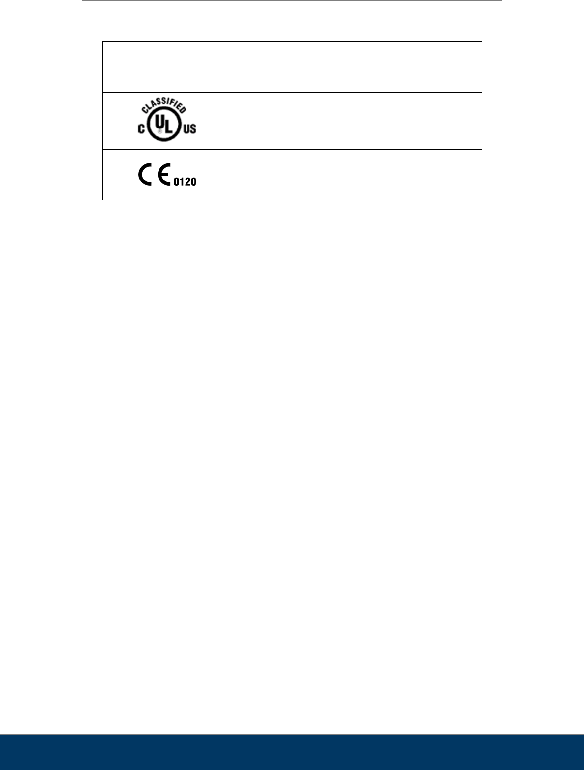
Chapter 5. Symbols
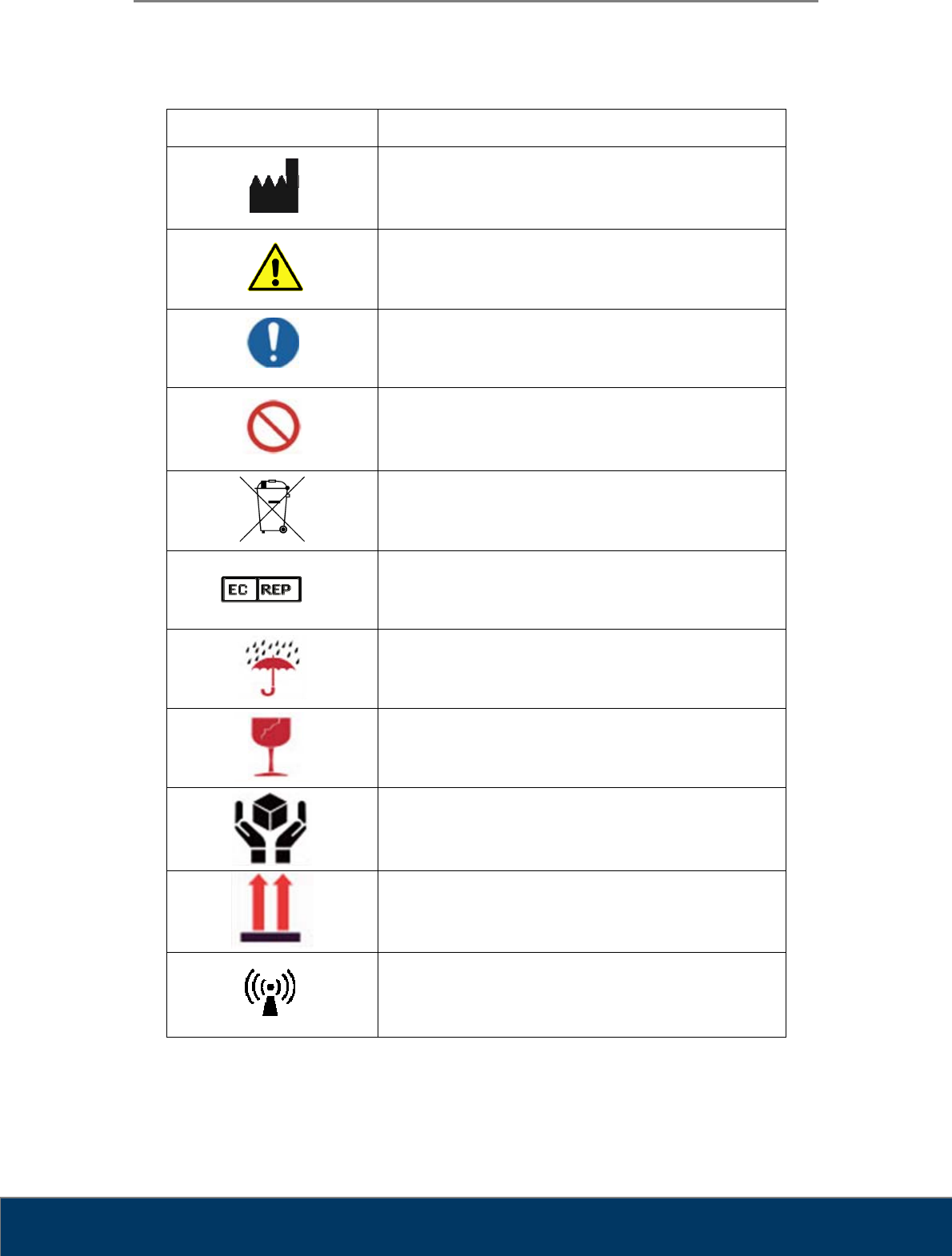
Symbol Description
Manufacturer
Warning, Consult Accompany Documents
General mandatory action manual
General prohibition indication
Directive on Waste Electrical and Electronic Equipment
Authorised Representative in the European
Community
Keep Dry
Fragile
Handle with care
This side up
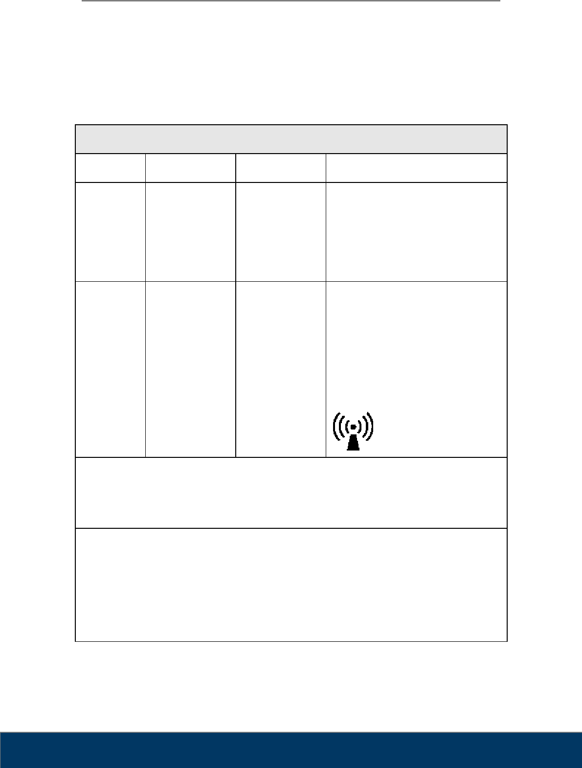
Non-ionizing electromagnetic radiation
User Manual
Fire ID TM-801-EN
16
FCC ID :
X68CRSCANNER4 FCC Mark
Medical Equipment
WITH RESPECT TO ELECTRIC SHOCK
FIRE, AND MECHANICAL HAZARDS ONLY
IN ACCORDANCE WITH UL60601-1 / CAN / CSA CSS.2 No. 601.1
3SE3
CE Mark
User Manual
Fire ID TM-801-EN
17
5.1. Manufacturer’s Declaration- Electromagnetic Emission
The Fire ID system is intended for use in the electromagnetic environment specified below. The
customer or the user of Fire ID system should assure that it is used in such an environment
Emission test Compliance Electromagnetic environment - guidance
RF emissions
CISPR 11
Group 1
Class B
The Fire ID system uses RF energy only for its
internal function. Therefore. Its RF emissions are
very low and are not likely to cause any
interference in nearby electronic equipment
5.2. Manufacturer’s Declaration - Electromagnetic Immunity
The Fire ID system is intended for use in the electromagnetic environment specified below. The
customer or the user of Fire ID system should assure that it is used in such an environment
Immunity test IEC 60601
Test level Compliance level Electromagnetic
Environment -guidance
Conducted RF
IEC 61000-4-6
3 Vrms
150 kHz to 80 MHz
3 Vrms
150 kHz to 80 MHz Portable and mobile RF
communications equipment
should be used no closer to
any part of the Fire ID system,
including cables, than the
recommended separation
distance calculated from the
equation applicable to the
frequency of the transmitter.
Recommended separation
distance
User Manual
Fire ID TM-801-EN
18
Radiated RF
IEC 61000-4-3
3 V/m
80.0 MHz to 2.5 GHz
3 V/m
80.0 MHz to 2.5 GHz
Recommended separation
distance
Where P is the maximum
output power rating of the
transmitter in watts (W)
according to the transmitter
manufacturer and d is the
recommended separation
distance in meters (m).
Field strengths from fixed RF
transmitters, as deter-mined by
an electromagnetic site survey,
(a) Should be less than the
compliance level in each
frequency range (b).
Interference may occur in the
vicinity of
equipment marked with the
following symbol:
Note 1) At 80 MHz and 800 MHz, the higher frequency range applies.
Note 2) These guidelines may not apply in all situations. Electromagnetic propagation is affected by
absorption and reflection from structures, objects and people.
a Field strengths from fixed transmitters, such as base stations for radio (cellular/cordless) telephones and
land mobile radios, amateur radio, AM and FM radio broadcast and TV broadcast cannot be predicted
theoretically with accuracy. To assess the electromagnetic environment due to fixed RF transmitters, an
electromagnetic site survey should be considered. If the measured field strength in the location in which the
EUT is used exceeds the applicable RF compliance level above, the EUT should be observed to
verifynormal operation. If abnormal performance is observed, additional measures may be necessary, such
as re-orienting or relocating the EUT.
b Over the frequency range 150 kHz to 80 MHz, field strengths should be less than [V1] V / m.
Recommended Separation Distances Between Portable and Mobile RF Communications
Equipment and the Fire ID system.
The Fire ID system is intended for use in an electromagnetic environment in which radiated RF
disturbances are controlled. The user of the Fire ID system can help prevent electromagnetic
interference by maintaining a minimum distance between portable and mobile RF
communications equipment (transmitters) and the Fire ID system as recommended below,
according to the maximum output power of the communications equipment.
Rated maximum output Separation distance (m) according to frequency of transmitter
User Manual
Fire ID TM-801-EN
19
power (W) of transmitter 150 kHz to 80 MHz 80 MHz to 800 MHz 800 MHz to 2.5
GHz
0.01 0.12 0.12 0.23
0.1 0.37 0.37 0.74
1 1.17 1.17 2.33
10 3.70 3.70 7.37
100 11.70 11.70 23.30
For transmitters rated at a maximum output power not listed above, the recommended separation
distance (d) in meters (m) can be estimated using the equation applicable to the frequency of the
transmitter, where P is the maximum output power rating of the transmitter in watts (W) according
to the transmitter manufacturer.
Note 1: At 80 MHz and 800 MHz, the separation distance for the higher frequency range applies.
Note 2: These guidelines may not apply in all situations. Electromagnetic propagation is affected
by absorption and reflection from structures, objects, and people.
Immunity and Compliance Level
Immunity test IEC 60601 Test Level Actual Immunity Level Compliance Level
Conducted RF
IEC 61000-4-6
3 Vrms, 150 kHz to 80
MHz
3 Vrms, 150 kHz to 80
MHz
3 Vrms, 150 kHz to 80
MHz
Radiated RF
IEC 61000-4-3
3 V/m, 80 MHz to 2.5
GHz
3 V/m, 80 MHz to 2.5
GHz
3 V/m, 80 MHz to 2.5
GHz
User Manual
Fire ID TM-801-EN
20
5.3. Guidance and Manufacturer’s Declaration –
Electromagnetic Immunity
The Fire ID system is intended for use in the electromagnetic environment specified below. The
customer or the user of Fire ID system should assure that it is used in such an environment
Immunity test IEC 60601
Test level Compliance level Electromagnetic environment -
guidance
Conducted RF
IEC 61000-4-6
3 Vrms
150 kHz to 80MHz
3 Vrms
150 kHz to 80 MHz Fire ID system must be used only in a
shielded location with a minimum RF
shielding effectiveness and, for each
cable that enters the shielded location
with a minimum RF shielding
effectiveness and, for each cable that
enters the shielded location
Radiated RF
IEC 61000-4-3
3 V/m
80.0 MHz to 2.5GHz
3 V/m
80.0 MHz to 2.5GHz
Field strengths outside the shielded
location from fixed RF transmitters, as
determined by an electromagnetic site
survey, should be less than 3V/m.a
Interference may occur in the vicinity of
equipment marked with the following
symbol:
Note 1) These guidelines may not apply in all situations. Electromagnetic propagation is affected
by absorption and reflection from structures, objects and people.
Note 2) It is essential that the actual shielding effectiveness and filter attenuation of the shielded
location be verified to assure that they meet the minimum specification.
a- Field strengths from fixed transmitters, such as base stations for radio (cellular/cordless)
telephones and land mobile radios, amateur radio, AM and FM radio broadcast and TV broadcast
cannot be predicted theoretically with accuracy. To assess the electromagnetic environment due to
fixed RF transmitters, an electromagnetic site survey should be considered. If the measured field
strength outside the shielded location in which the EUT is used exceeds 3V/m, the EUT should be
observed to verify normal operation.
If abnormal performance is observed, additional measures may be necessary, such as relocating
the EUT or using a shielded location with a higher RF shielding effectiveness and filter attenuation.

User Manual
Fire ID TM-801-EN
21
Chapter 6. Warranty and Repair Service
6.1. Standard Warranty
3D Imaging & Simulations Corp. warrants its non-consumable hardware products to be free
from defects in materials and workmanship. The warranty covers the cost of parts and labor to
repair the product. Please keep the shipping box for future use.
The warranty is valid when the product is used for its intended purpose and does not cover
products which have been modified without written permission from 3D Imaging & Simulations
Corp., or which have been damaged by abuse, accident or connection to incompatible
equipment.
This warranty is in lieu of all other warranties, expressed or implied.
6.2. Repair Service
The company reserves the right to cease providing repair maintenance, parts and technical
support for its non-consumable hardware products five years after a product is discontinued.
Technical support for old versions of software products will cease 12 months after they are
upgraded or discontinued.
6.3. Out of Warranty Repair Service
Out of warranty repair service is available in selected geographical locations. Contact the
supplier for current terms and rates.

User Manual
Fire ID TM-801-EN
22
6.4. Shipping
The Fire ID is a solidly built system designed to survive shipping around the world. However,
in order to avoid damage during shipping, the Fire ID must be properly packaged.
In general, the best way to package the Fire ID is in the original factory container. If this is no
longer available, we recommend that user carefully wraps the Fire ID in at least 75 mm (3 inch)
of foam or bubble pack sheeting. The wrapped device should then be placed in a sturdy
cardboard carton. Mark the outside of the box with word FRAGILE and an arrow showing
which way is up.
We do not recommend using loose foam pellets to protect the Fire ID. If the carton is dropped
by the shipper, there is a good chance that the device will shift within the loose pellet packing
and be damaged.
If user needs to ship the Fire ID to another location, or back to the factory, and user does not
have a means to adequately package it, user can order additional shipping container. This
may seem an expense user would like to avoid, but it is inexpensive compared to the cost of
repairing an instrument that has sustained shipping damage.
It is user’s responsibility to package the system properly before shipping. If the packaging is
inadequate, and the system is damaged during shipping, the shipper will not honor user’s claim
for compensation.

User Manual
Fire ID TM-801-EN
23
Chapter 7. Technical Assistance
If user has any questions about installing or using the device, contact your 3D Imaging &
Simulations Corp representative or your local dealer.
3D Imaging & Simulations Corp.
815, Tamnip-Dong, Yuseong-Gu, Daejeon, Korea
Tel : 82-42-931-2100 Fax : 82-42-931-2299
www.3DISCimaging.com

User Manual
Fire ID TM-801-EN
24
Appendix I
Installation Report
Please complete this report at the time of installation and submit the
completed form signed by customer to:
Fax : +82-42-931-2299
E-mail : support@3DISCimaging.com
Date of Installation :
Customer Information
Hospital / Institute
Name
Address
Tel
Fax
E-mail
Installer Information
Company
Name
Address
Tel
Fax
E-mail
System Information
Model RFID Reader
System S/N
Installer’s Signature: Date:
Customer’s Signature: Date: