DLP Design 000RF2 Short Range Transceiver User Manual DLP RF2 Data Sheet
DLP Design, Inc. Short Range Transceiver DLP RF2 Data Sheet
UserManual.wiki
>
DLP Design
>
000RF2 User Manual
Users Manual Revision 2
Navigation menu
Upload a User Manual
Namespaces
Wiki Guide
HTML
PDF
Info
Views
User Manual
Discussion / Help
Navigation
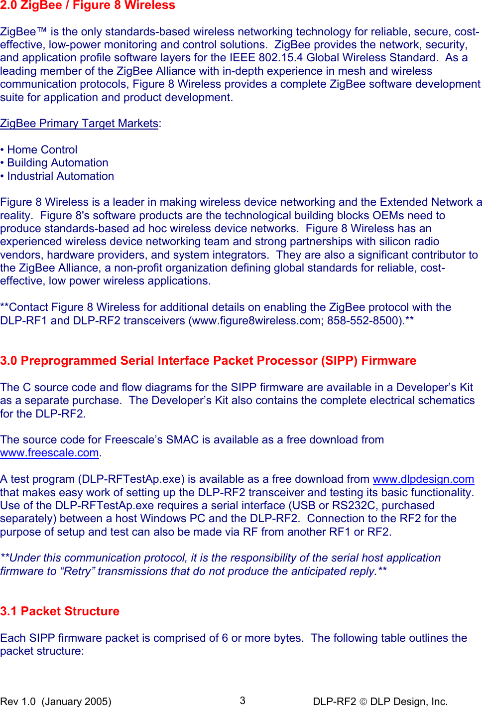
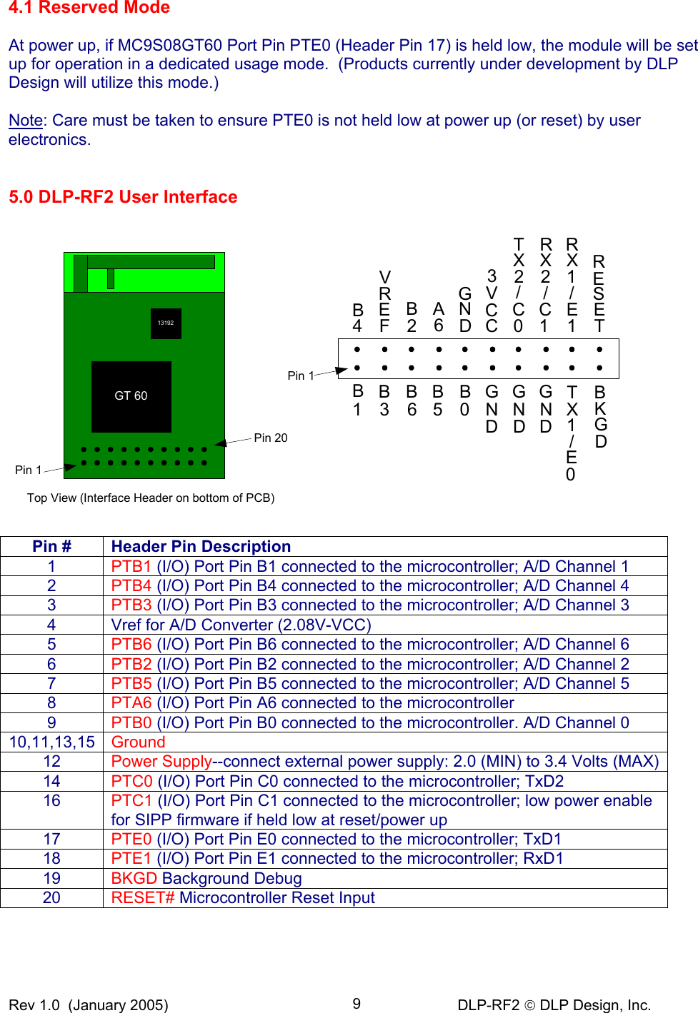
![Rev 1.0 (January 2005) DLP-RF2 DLP Design, Inc. 70xB7 MC9S08GT60 Return Board ID (not available through RF transceiver) 0xCF 0xB8 MC9S08GT60 Read VBAT (DLP-RF2 only; additional hardware required) 0xCB 0xB9 MC9S08GT60 Read Temperature (DLP-RF2 only; additional hardware required) 0xCC 0xC0 Serial / USB Generic Reply or “ACK” for all non-broadcast commands 0xC1 Serial / USB Check-in from DLP-RF2 due to monitored port pin input change 0xC2 Serial / USB Check-in from DLP-RF2 due to wake from sleep 0xC3 Serial / USB Measured energy data 0xC4 Serial / USB EEPROM read reply 0xC5 Serial / USB Write EEPROM reply 0xC6 Serial / USB Read I/O pin reply 0xC7 Serial / USB Set direction reply 0xC8 Serial / USB Set/Clear I/O pin reply 0xC9 Serial / USB Setup A/D reply 0xCA Serial / USB Read A/D reply 0xCB Serial / USB Read VBAT reply 0xCC Serial / USB Read Temperature reply 0xCD Serial / USB Return board type--uC ROM and RF IC versions 0xCE Serial / USB No-header packet reply 0xCF Serial / USB Return ID Example: Below is a simple C program illustrating the Ping (0xA0) Command. This assumes the presence of a transceiver with an ID of 1 issuing the Ping command and a second transceiver with an ID of 0x13 (19 decimal) to receive and respond to the Ping command: int m_DestID = 0x0013; int m_SourceID = 0x0001; unsigned char rx[126], tx[126]; int pos=1;//init packet index tx[pos++] = (unsigned char)((m_DestID&0xff00)>>8); //Destination ID MSB tx[pos++] = (unsigned char)(m_DestID&0x00ff); //Destination ID LSB tx[pos++] = (unsigned char)((m_SourceID&0xff00)>>8); //Source ID MSB tx[pos++] = (unsigned char)(m_SourceID&0x00ff); //Source ID LSB tx[pos++] = 0xA0;//Command byte: Ping tx[0] = pos-1;//assign number of bytes in packet to position zero PutBuffer(tx, pos);//send tx out serial port GetBuffer(rx, 6, TIMEOUTWAIT); //wait up to timeout for 6 bytes to return if(rx[5] != 0xC0)//if Buffer Position 5 is not the expected reply (0XC0) { //No reply to the Ping command //either retry the command or process the error }](https://usermanual.wiki/DLP-Design/000RF2/User-Guide-520547-Page-7.png)
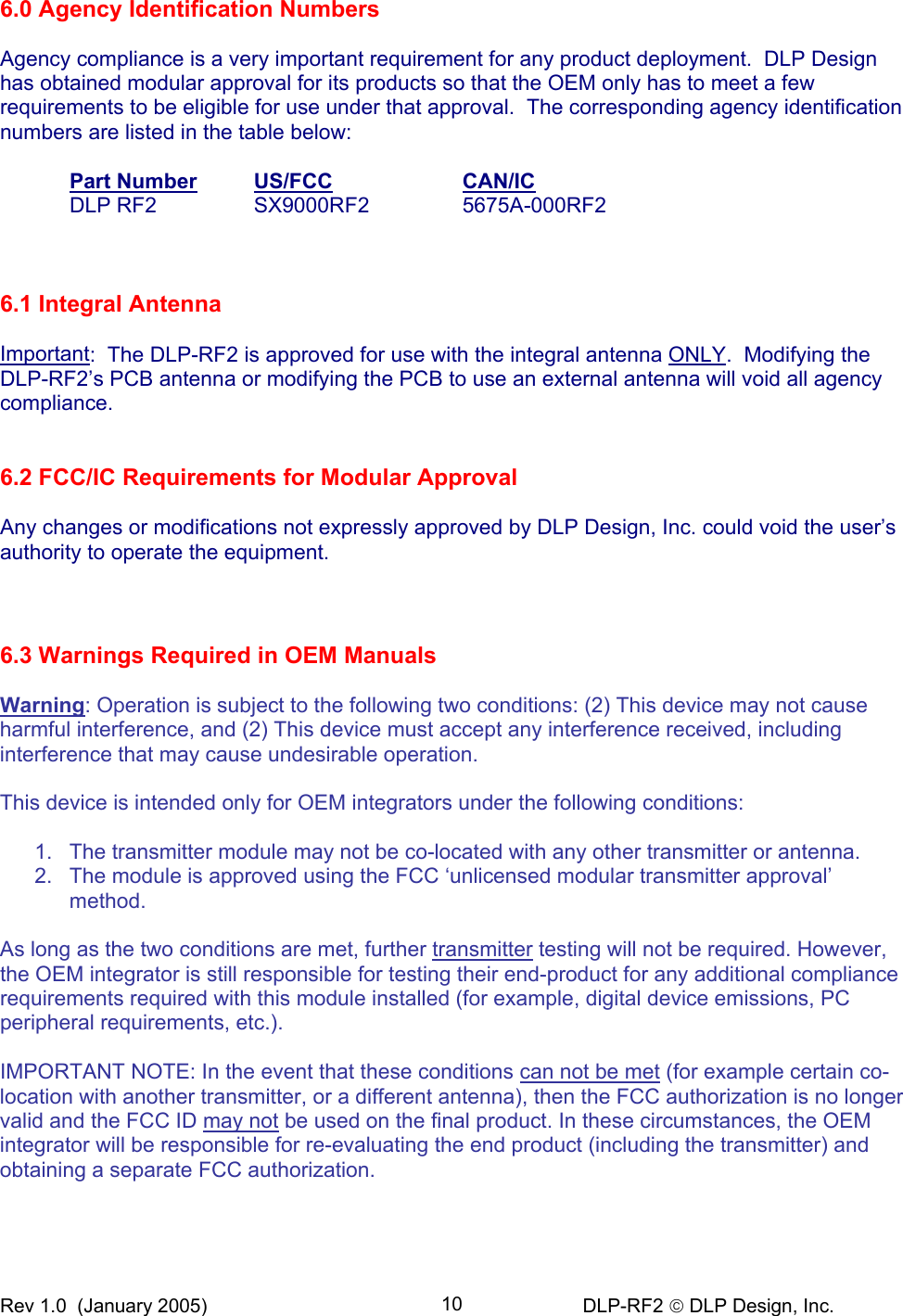
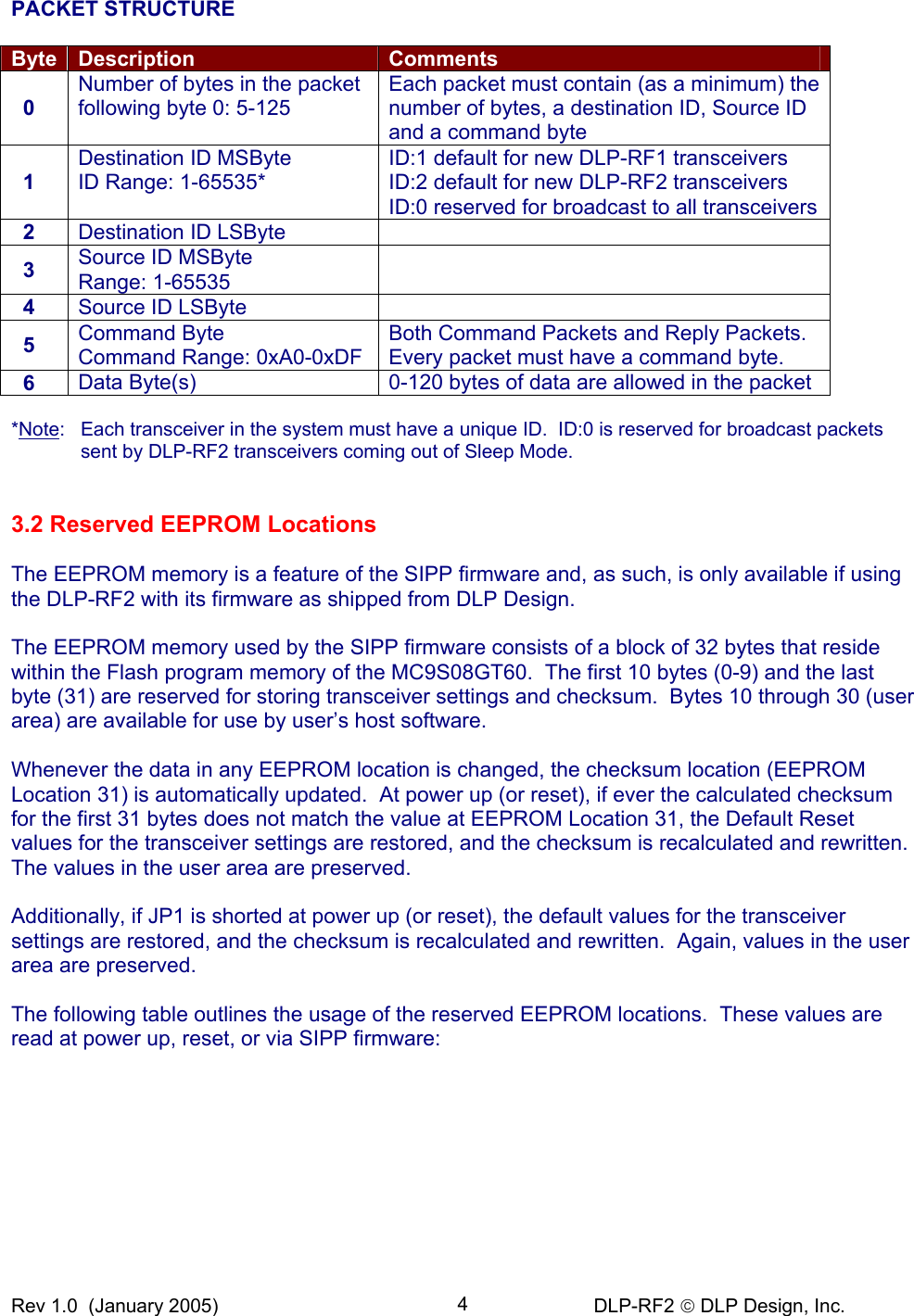
![Rev 1.0 (January 2005) DLP-RF2 DLP Design, Inc. 84.0 Low-Power Mode (RF2 Only) At power up, if MC9S08GT60 Port Pin PTC1 (Header Pin 16) is held low, the module will check the initial state of selected port pins and immediately enter Low-Power Mode. This mode is a feature of the SIPP firmware and is only available if using the DLP-RF2 with its firmware as shipped from DLP Design. If pull-ups are enabled and the port pin is held low, then shutdown current will be higher. Also, if the user electronics draw any current from port pins in Sleep Mode, then the shutdown current will be higher. In this state, the MC13192 transceiver IC is in Hibernate Mode, and the MC9S08GT60 is in Stop Mode. Total current draw for the DLP-RF2 module in this state is specified at less than 35 microamps at 3V. The data byte stored at EEPROM Location 8 contains a bit field that is used to select which port pins are to be watched for any change while in Low-Power or Idle Mode. For example, if a “1” is set for Bit 7 at EEPROM Location 8, and if Port Pin PTA6 is set up as a digital input, and the state of PTA6 changes (low to high, or high to low), then the MC9S08GT60 is brought out of Low-Power Mode, and a packet is sent as a broadcast packet (Source ID=0) containing Command 0xC1. Bit Position: D7 D6 D5 D4 D3 D2 D1 D0 EEPROM [8] Port Pin: A6 B6 B5 B4 B3 B2 B1 B0 The data bytes stored at EEPROM Locations 4 and 5 hold values that, when combined, are used to set the length of time that the DLP-RF2 will remain asleep or in Low-Power Mode. The range of time that the DLP-RF2 can be left asleep is from 5 seconds to 3.8 days. When this amount of time has elapsed, the MC9S08GT60 is brought out of Low-Power Mode, and a packet is sent as a broadcast packet (Destination ID=0) containing Command 0xC2. The DLP-RF2 transmits a broadcast packet (Destination ID=0) for either wake from sleep or change of a selected digital input. It is the user’s responsibility to establish a DLP-RF1 or DLP-RF2 transceiver as a system controller to receive and process this packet. (Note that multiple transceivers can be set up as system controllers as long as only one responds to a wake-from-sleep packet from a specific DLP-RF2.) If the DLP-RF2 does not receive a reply to this packet after a preset length of time, it will return to Sleep Mode to conserve battery power. Command 0xA4 can be sent to the DLP-RF2 to instruct it to return to Sleep Mode immediately, or the system controller can first request data from the DLP-RF2 before instructing it to return to sleep. The data byte stored at EEPROM Location 6 contains a value that determines how many half-seconds a DLP-RF2 will remain awake waiting for a response from the system controller. If this value is set to 1 (for example), then the DLP-RF2 will transmit its wake-from-sleep packet, wait for 500 milliseconds for a reply, and retry one additional time before giving up and returning to sleep.](https://usermanual.wiki/DLP-Design/000RF2/User-Guide-520547-Page-8.png)