DLP Design UHF1B RFID Transmitter User Manual DLP RFID UHF1B Datasheet v34b
DLP Design, Inc. RFID Transmitter DLP RFID UHF1B Datasheet v34b
user manual
Rev 1.1 (April 2009) 1 © DLP Design, Inc.
D
DL
LP
P-
-R
RF
FI
ID
D-
-
U
UH
HF
F1
1B
B
LEAD FREE
C
CL
LA
AS
SS
S
1
1/
/G
GE
EN
N
2
2
R
RF
FI
ID
D
R
RE
EA
AD
DE
ER
R-
-W
WR
RI
IT
TE
ER
R
**PRELIMINARY DOCUMENT-SUBJECT TO CHANGE**
FEATURES:
• ISO 18000, EPC Class 1–Gen 2 Compatible
• Read UID of Up to 15 Tags Simultaneously
• 18dBm Output Power
• UHF Reader/Writer
• Reverse Polarity SMA Antenna Connector
• FCC/IC/CE Modular Approval Pending
• Permanent, Unique Serial Number Accessible via USB
• Integrated Pass/Fail Beeper
• USB Port Powered from the Host PC (USB 1.1/2.0 Compatible)
• USB Drivers Provided for Windows Vista, XP, XPx64, Server2003, 2000
• Software Development Library Support for Visual
C++/Visual Basic
APPLICATION AREAS:
• Real-Time Security
• Personal Identification
• Pharmaceutical Tracking
• Inventory/Asset Management & Tracking
• Library/Book Management & Tracking
• Baggage Tagging
• Sports Event Timing

Rev 1.1 (April 2009) 2 © DLP Design, Inc.
1.0 INTRODUCTION
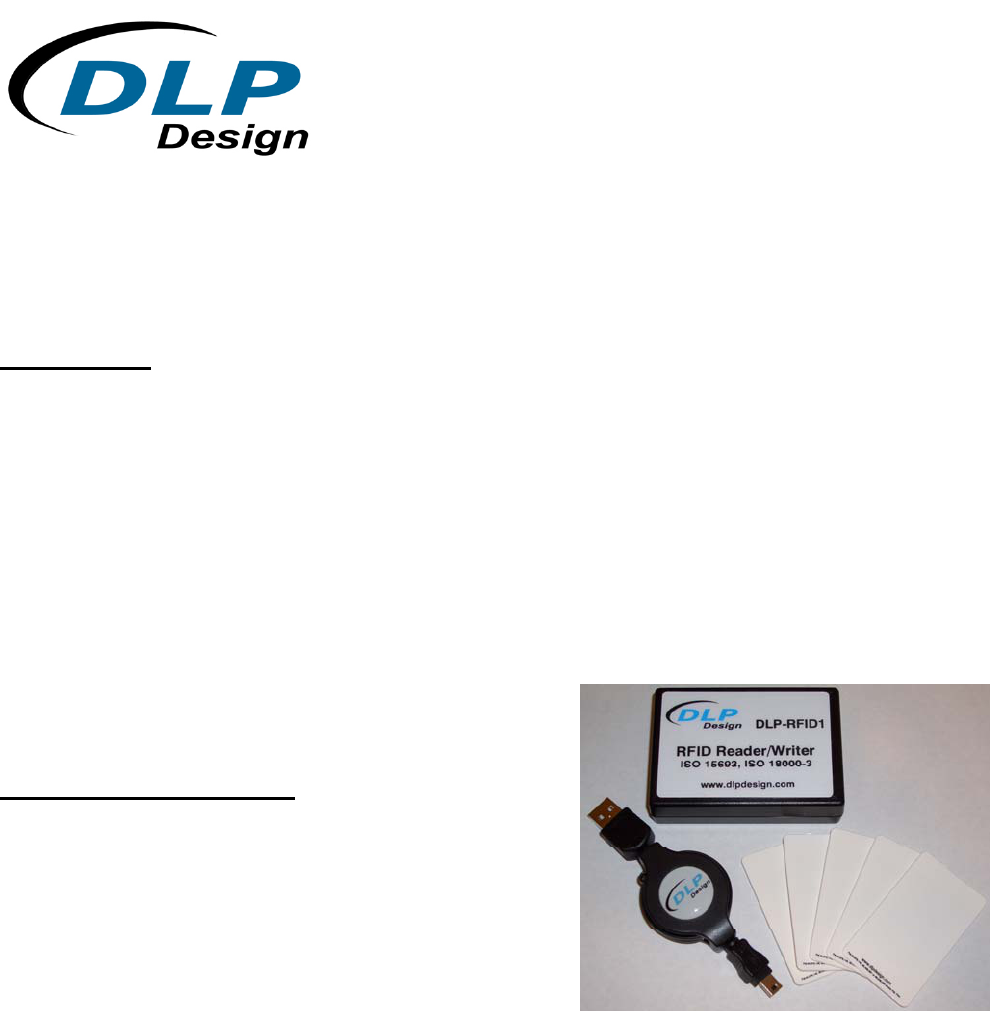
Note: The retail boxed version of this product includes the DLP-RFID-UHF1B reader, a
retractable USB cable, a small loop antenna, 3-foot coax and two UHF RFID tags.
The DLP-RFID-UHF1B is a low-cost, USB-powered module for reading from and writing to ISO
18000-6a, -6b and -6c intelligent RFID transponder tags. It has the ability to both read and write
data in addition to reading the unique identifier (UID). All of the DLP-RFID-UHF1B’s electronics
reside within the compact unit, and all operational power is taken from the host PC via the USB
interface.
2.0 RFID BASICS
RFID stands for Radio Frequency IDentification. It is an electronic technology whereby digital
data encoded in an RFID tag (or transponder) is retrieved utilizing a reader. In contrast to bar
code technology, RFID systems do not require line-of-sight access to the tag in order to retrieve
the tag’s data, and they are well suited to harsh environments.
An RFID tag consists of an integrated circuit attached to an antenna. In the case of the tags
used with the DLP-RFID-UHF1B, the antenna is in the form of conductive ink “printed” onto a
material that allows for connection to the integrated circuit. This type of passive (battery-free)
tag is commonly referred to as an “inlay”.
The RFID reader (or “interrogator”) is typically a microcontroller-based radio transceiver that
powers the tag with a time-varying electromagnetic radio frequency (RF) field. When the RF
field passes through the tag’s antenna, AC voltage is generated in the antenna and rectified to
supply power to the tag. Once powered, the tag can receive commands from the reader. The
information stored in the tag can then be read by the reader and sent back to the host PC for
processing.
The data in the tag consists of a hard-coded, permanent serial number (or UID) and user
memory that can be written to, read from and locked if desired. Once locked, user data can still
be read but not changed.

Rev 1.1 (April 2009) 3 © DLP Design, Inc.
3.0 SPECIFICATIONS
Reader Frequency 902.6-927.4MHz
Output Power 18dBm MAX
Range 1-6 inches (Depends upon the type of RFID tag)
Tags/Protocols Supported ISO18000-6a, 6b and 6C
Communications Interface USB 1.1/2.0 Compatible; Mini-B 5-Pin Connector
Operational Power – Active 320mA
Operational Power – Idle 45mA
Antenna Connector Reverse Polarity SMA*
USB Driver Support Windows Vista, XP, XPx64, Server2003, 2000,
Linux, Mac OSX
Physical Dimensions – Retail Enclosure: .83x2.3x3.25” typ. (21.1x58.4x82.6mm)
Operating Temperature 0-70°C
*Please see the Antenna Section for important regulatory details.
4.0 PERMANENT READER SERIAL NUMBER
Each DLP-RFID-UHF1B contains a unique, 32-bit, hard-coded serial number that cannot be
altered by any means. The serial number can be read via the USB interface and used to
identify the reader via the host software.
5.0 APPLICATION DEVELOPMENT
A software library is available for free download upon purchase of the DLP-RFID-UHF1B that
demonstrates reading the serial number (UID) from transponder tags, writing to the tags,
accessing the reader’s permanent serial number and controlling the integrated pass/fail beeper.
Additionally, a low-power Mode Enable command is provided to reduce current consumption to
approximately 45mA when communication with a tag is not required.
Rev 1.1 (April 2009) 4 © DLP Design, Inc.
6.0 REGULATORY AGENCY CONSIDERATIONS
6.1 AGENCY IDENTIFICATION NUMBERS
Compliance with the appropriate regulatory agencies is essential in the deployment of all
transceiver devices. DLP Design will obtain modular approval for this RF product such that an
OEM need only meet a few basic requirements in order to utilize their end product under this
approval. Corresponding agency identification numbers will be listed below:
Part Number US / FCC CANADA / IC
DLP-RFID-
UHF1B SX9UHF1B 5675A-UHF1B
6.2 EXTERNAL ANTENNAS
The DLP-RFID-UHF1B will be approved for use with selected external antennas. Connection is
made via reverse-polarity SMA connectors.
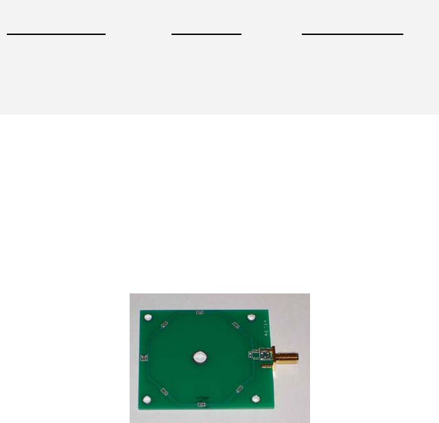
A magnetic loop antenna is provided with each DLP-RFID-UHF1B reader purchased from DLP
Design as shown below:
This antenna is well suited for reading the near-field loop incorporated into many Gen-2 tags.
This antenna requires a coax cable with a reverse-polarity SMA connector at one end for
connection to the DLP-RFID-UHF1B reader. A 3-foot coax cable is provided with each DLP-
RFID-UHF1B reader purchased from DLP Design.
6.3 FCC/IC REQUIREMENTS FOR MODULAR APPROVAL
Any changes or modifications to the DLP-RFID-UHF1B’s printed circuit board or magnetic loop
antenna could void the user’s authority to operate the equipment.
6.4 WARNINGS

Rev 1.1 (April 2009) 5 © DLP Design, Inc.
Operation is subject to the following two conditions: (1) This device may not cause harmful
interference, and (2) this device must accept any interference received, including interference
that may cause undesirable operation.
This device is intended for use under the following conditions:
1. The transmitter module may not be co-located with any other transmitter or antenna; and,
2. The module will be approved using the FCC’s “unlicensed modular transmitter approval”
method. Only loop antennas which do not exhibit a directional gain greater than that of the
antenna approved with the device may be used.
As long as these two conditions are met, further transmitter testing will not be required.
However, the OEM integrator is still responsible for testing their end product for any additional
compliance measures necessitated by the installation of this module (i.e. digital device
emissions, PC peripheral requirements, etc.).
Note: In the event that these conditions cannot be met (i.e. co-location with another
transmitter), then the FCC authorization is no longer valid, and the corresponding FCC ID may
not be used on the final product. Under these circumstances, the OEM integrator will be
responsible for re-evaluating the end product (including the transmitter) and obtaining a
separate FCC authorization.
6.5 OEM PRODUCT LABELING
The final end product must be labeled in a visible area with the following text:
“Contains TX FCC ID: SX9UHF1B”
6.6 RF EXPOSURE
In order to comply with FCC RF exposure requirements, the antenna used for this transmitter
must not be co-located or operating in conjunction with any other antenna or transmitter.
6.7 ADDITIONAL INFORMATION FOR OEM INTEGRATORS
The end user should NOT be provided with any instructions on how to remove or install the
DLP-RFID-UHF1B. This device will be pre-certified to operate with the antenna models listed
below:
• DLP Design Near-Field Magnetic Loop Antenna
7.0 DISCLAMER
Rev 1.1 (April 2009) 6 © DLP Design, Inc.
Neither the whole nor any part of the information contained herein nor the product described in
this datasheet may be adapted or reproduced in any material or electronic form without the prior
written consent of the copyright holder.
This product and its documentation are supplied on an as-is basis, and no warranty as to their
suitability for any particular purpose is either made or implied. DLP Design will not accept any
claim for damages whatsoever arising as a result of the use or failure of this product. Your
statutory rights are not affected.
This product or any variant of it is not intended for use in any medical appliance, device or
system in which the failure of the product might reasonably be expected to result in personal
injury.
This document provides preliminary information that may be subject to change without notice.
8.0 CONTACT INFORMATION
DLP Design, Inc.
1605 Roma Lane
Allen, TX 75013
Phone: 469-964-8027
Fax: 415-901-4859
Email: support@dlpdesign.com
Internet: http://www.dlpdesign.com