DMP ELECTRONICS AVL Auto Vehicle Locator (AVL) User Manual TechGuide AVL 1e3m7C
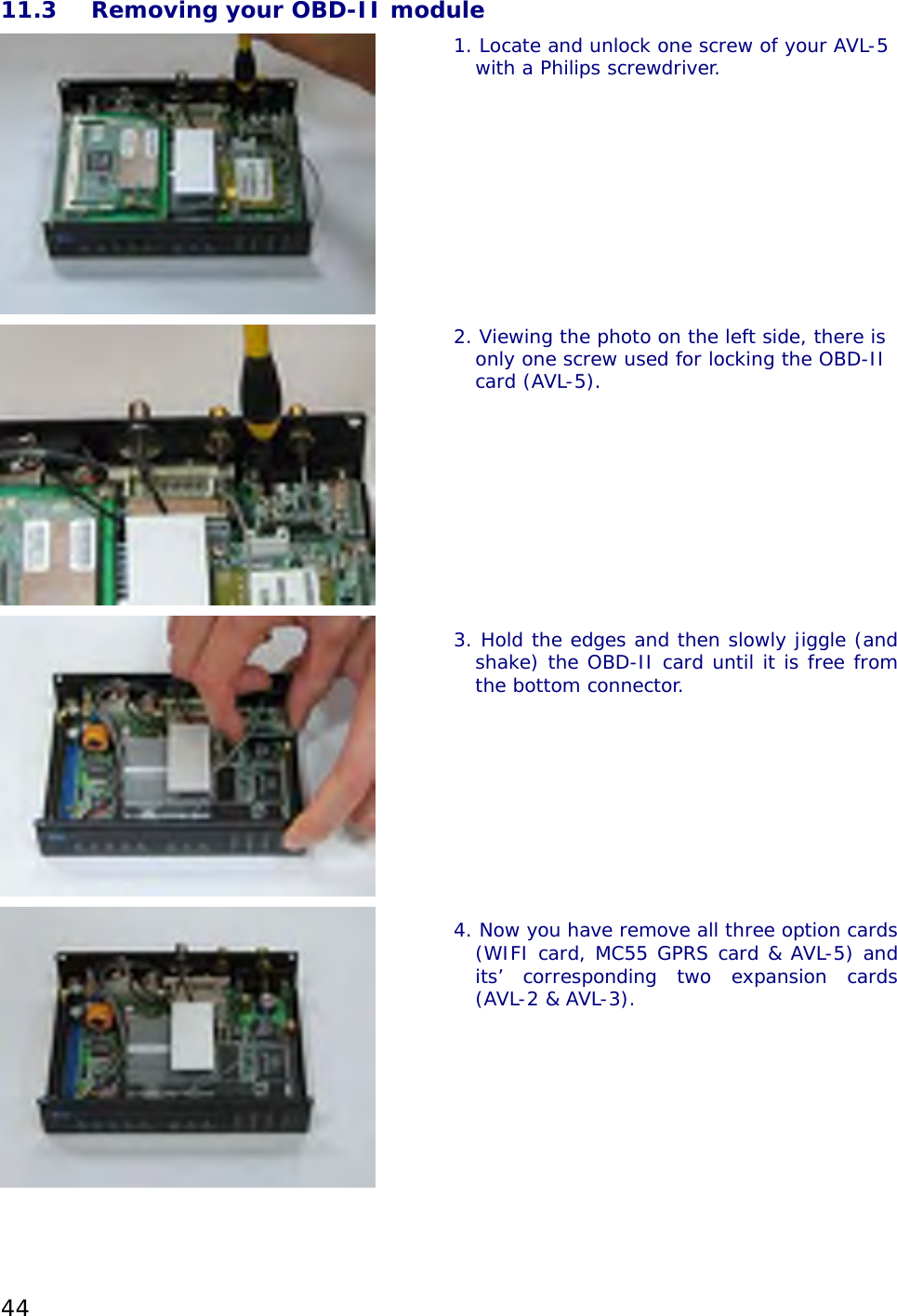
DMP ELECTRONICS INC. Auto Vehicle Locator (AVL) TechGuide AVL 1e3m7C
UserManual.wiki
>
DMP ELECTRONICS
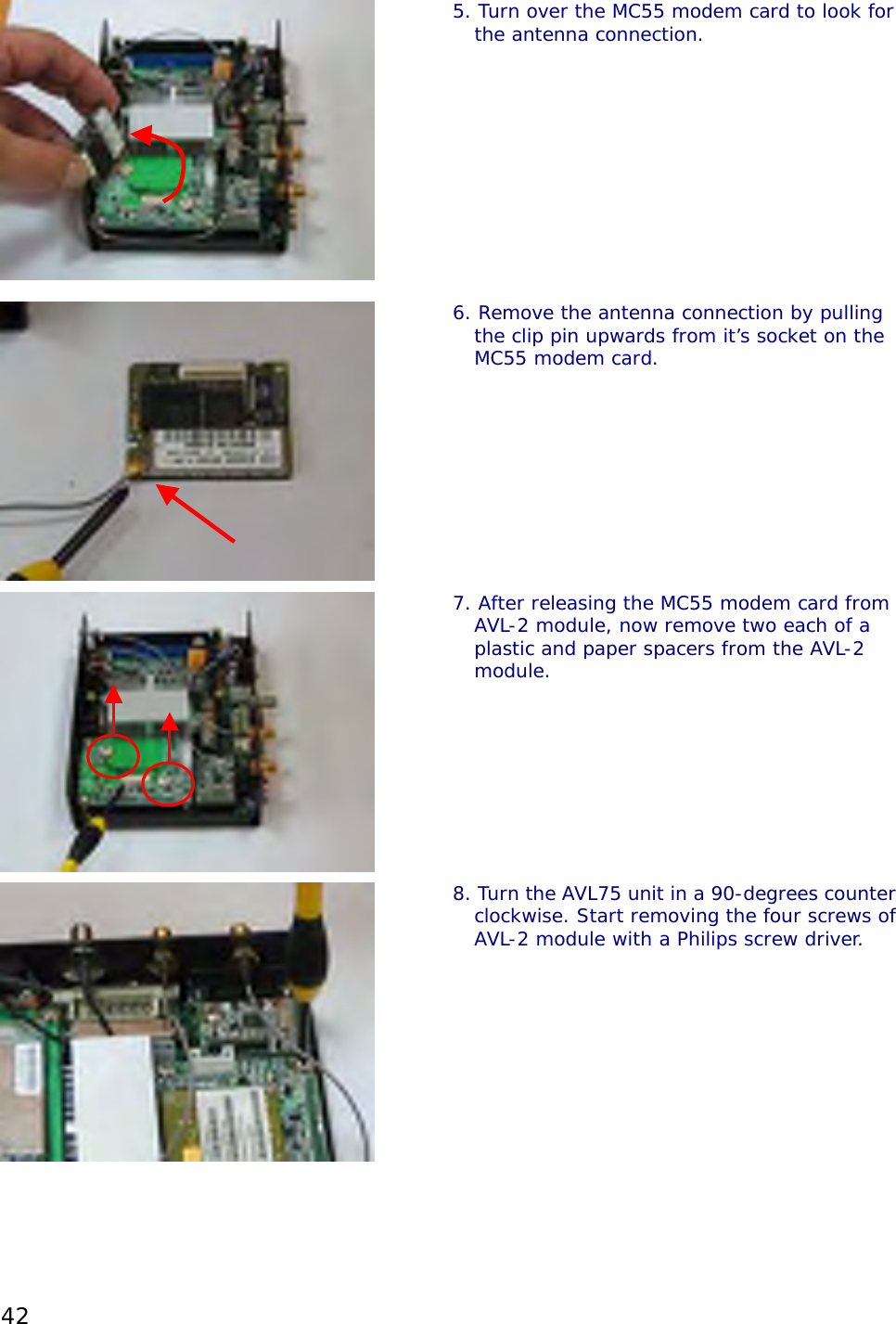
>
AVL User Manual
>
Users Manual Part II
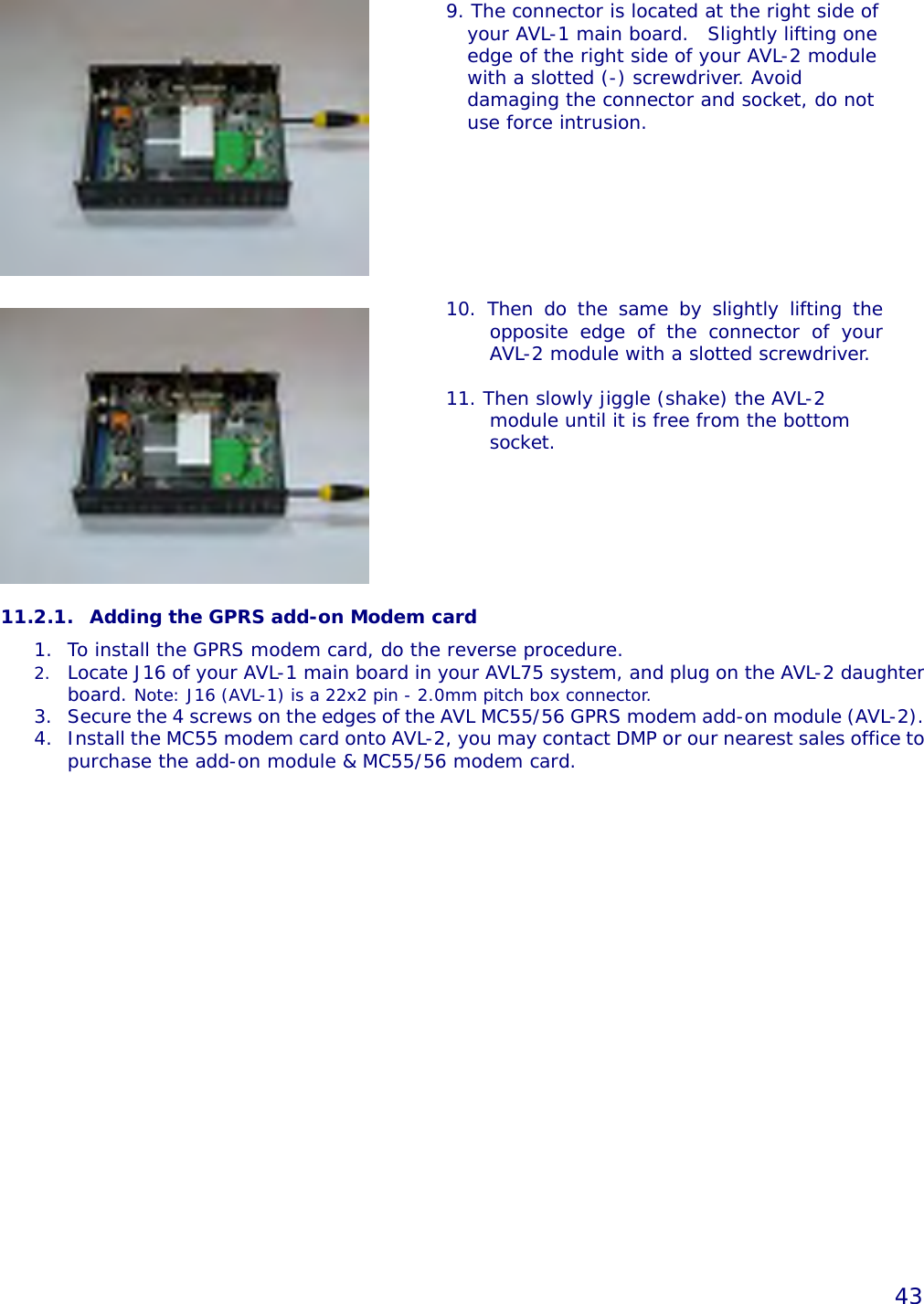
Contents
1.
Users Manual Part I
2.
Users Manual Part II
Users Manual Part II
Navigation menu
Upload a User Manual
Namespaces
Wiki Guide
HTML
PDF
Info
Views
User Manual
Discussion / Help
Navigation
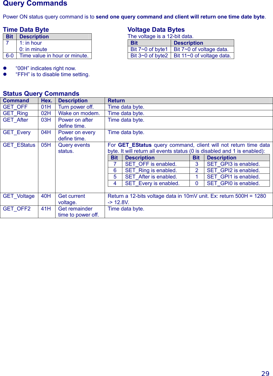
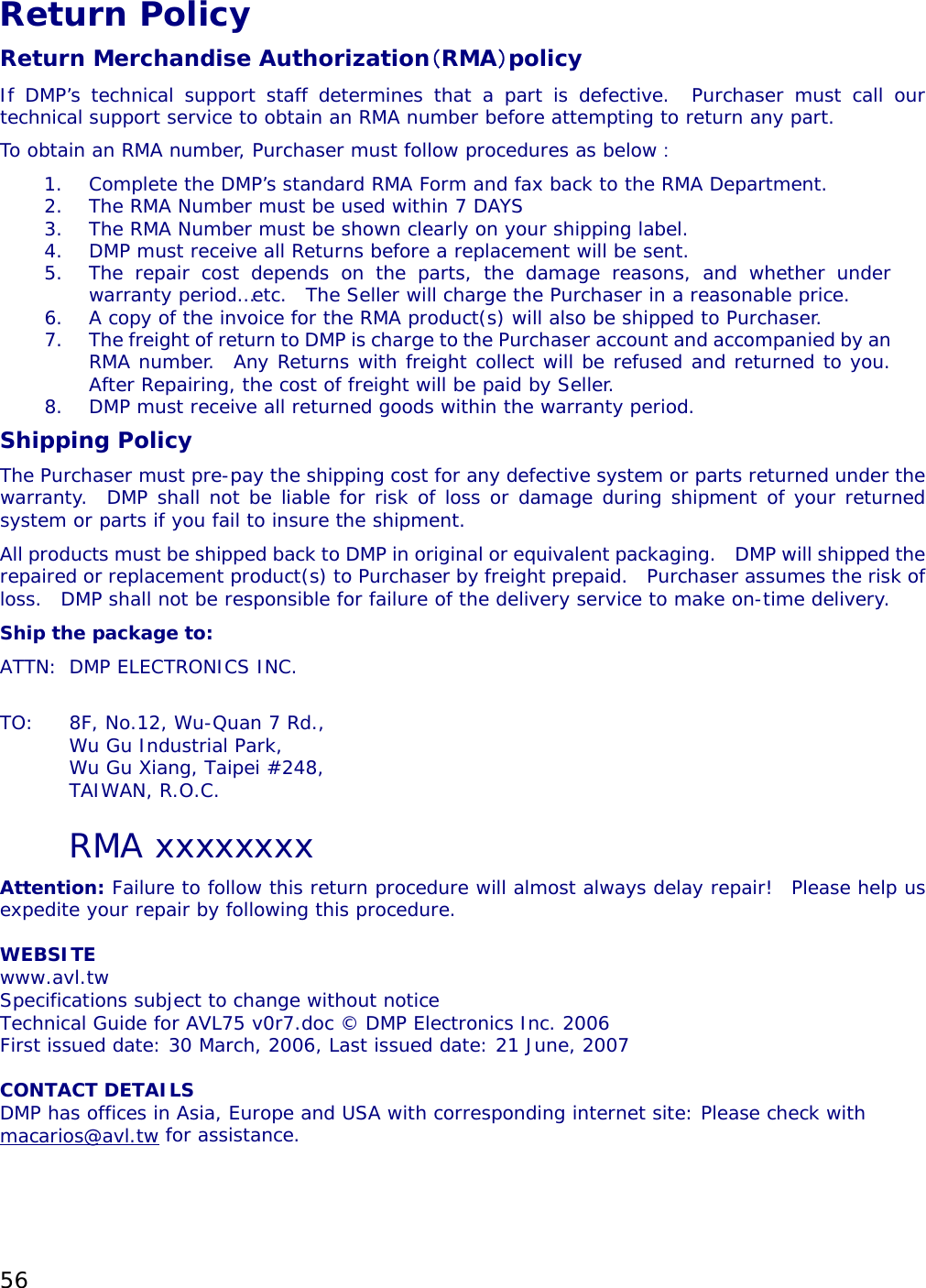
![36 // !! and do not execute command. !! // !! return false if pic is busy for execute command !! // event_type : power on event type, defined in AVL_POWER_WAKE_ON_* // h_m : means the t field in hour or minutes type, 0 for minutes, others for hour // t : how many hours(or minutes) to power on, 0 = power on when event trigged // : other values means delay [t] hours(or minutes) then power on. // : value from 0 ~ 126 bool AVL_POWER_disable_wake_on_event(int event_type); // clear the power on event // !! this function will return false when any argument error !! // !! and do not execute command. !! // !! return false if pic is busy for execute command !! // event_type : power on event type, defined in AVL_POWER_WAKE_ON_* bool AVL_POWER_clear_all_wake_on_event(); // clear all power on event // !! return false if pic is busy for execute command !! bool AVL_POWER_get_power_off_timer(int &h_m, int &t); // get power off timer setted before // !! return false if pic is busy for execute command !! // h_m : means the t field in hour or minutes type, 0 for minutes, others for hour // t : how many hours(or minutes) to power on, 0 = power on when event trigged // : other values means delay [t] hours(or minutes) then power on. // : value from 0 ~ 126 bool AVL_POWER_get_wake_on_timer(int event_type, int &h_m, int &t); // get event wake on timer setted before // !! this function will return false when any argument error !! // !! and do not execute command. !! // !! return false if pic is busy for execute command !! // event_type : power on event type, defined in AVL_POWER_WAKE_ON_* // h_m : means the t field in hour or minutes type, 0 for minutes, others for hour // t : how many hours(or minutes) to power on, 0 = power on when event trigged // : other values means delay [t] hours(or minutes) then power on. // : value from 0 ~ 126 bool AVL_POWER_get_event_status(AVL_POWER_Event_Status *event_status); // get event status, // !! return false if pic is busy for execute command !! // see struct AVL_POWER_Event_Status for more information bool AVL_POWER_get_input_status(AVL_POWER_Input_Status *input_status); // get input status, // see struct AVL_POWER_Input_Status for more information bool AVL_POWER_get_power_on_type(AVL_POWER_Power_On_Event_Type *power_on_type); // get power up event type // see struct AVL_POWER_Power_On_Event_Type for more information](https://usermanual.wiki/DMP-ELECTRONICS/AVL.Users-Manual-Part-II/User-Guide-819942-Page-15.png)
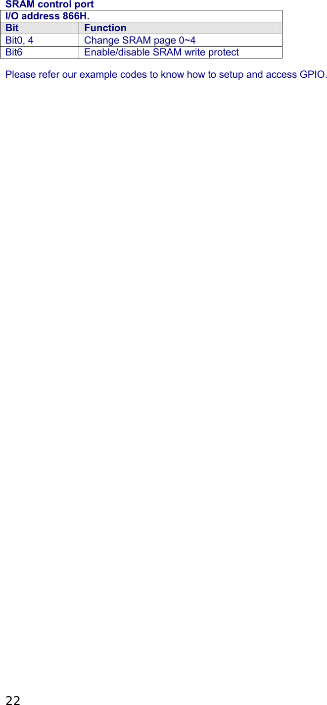
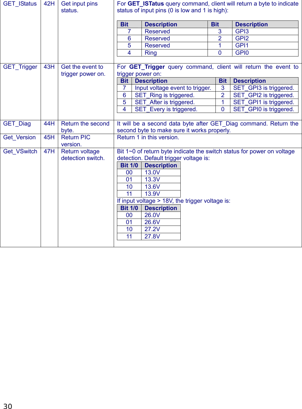
![37 bool AVL_POWER_get_current_voltage(float &val); // get current voltage data // !! return false if pic is busy for execute command !! bool AVL_POWER_get_remainder_time_to_power_off(int &h_m, int &t); // get remainder time to power off // !! return false if pic is busy for execute command !! // h_m : means the t field in hour or minutes type, 0 for minutes, others for hour // t : how many hours(or minutes) to power on, 0 = power on when event trigged // : other values means delay [t] hours(or minutes) then power on. // : value from 0 ~ 126 bool AVL_POWER_get_sw_setting(BYTE &val); // get the DIP SWITCH SETTING // !! return false if pic is busy for execute command !! Examples AVL_POWER_init(); // power off AVL right now AVL_POWER_power_off(0, 0); // power off AVL after 10 minutes AVL_POWER_power_off(0, 10); // power off AVL after 1 hour AVL_POWER_power_off(1, 1); // wake on ring AVL_POWER_wake_on_event(AVL_POWER_WAKE_ON_RING, 0, 0); // disable wake on ring AVL_POWER_disable_wake_on_event(AVL_POWER_WAKE_ON_RING); AVL_POWER_close(); Technical Support For more technical support, please visit http://www.dmp.tw/tech or mail to tech@dmp.tw AVL Power Management Programming Reference | 2006-04-25 End-of-AVL Power Management Programming Reference](https://usermanual.wiki/DMP-ELECTRONICS/AVL.Users-Manual-Part-II/User-Guide-819942-Page-16.png)